CN114963935A - Height detection device and detection method for O-shaped sealing oil groove - Google Patents
Height detection device and detection method for O-shaped sealing oil grooveDownload PDFInfo
- Publication number
- CN114963935A CN114963935ACN202210569382.4ACN202210569382ACN114963935ACN 114963935 ACN114963935 ACN 114963935ACN 202210569382 ACN202210569382 ACN 202210569382ACN 114963935 ACN114963935 ACN 114963935A
- Authority
- CN
- China
- Prior art keywords
- height
- workpiece
- oil groove
- positioning
- detection
- Prior art date
- Legal status (The legal status is an assumption and is not a legal conclusion. Google has not performed a legal analysis and makes no representation as to the accuracy of the status listed.)
- Pending
Links
- 238000001514detection methodMethods0.000titleclaimsabstractdescription58
- 238000007789sealingMethods0.000titleclaimsabstractdescription34
- 238000005259measurementMethods0.000claimsabstractdescription28
- 238000000034methodMethods0.000claimsabstractdescription18
- 230000008569processEffects0.000claimsabstractdescription14
- 239000002184metalSubstances0.000claimsdescription3
- 238000005266castingMethods0.000abstractdescription8
- 238000012545processingMethods0.000abstractdescription6
- 230000009471actionEffects0.000abstractdescription5
- 230000006872improvementEffects0.000description9
- 238000007689inspectionMethods0.000description7
- 230000007547defectEffects0.000description3
- 238000010586diagramMethods0.000description3
- 238000004519manufacturing processMethods0.000description3
- 230000008859changeEffects0.000description2
- 230000002093peripheral effectEffects0.000description2
- 230000009286beneficial effectEffects0.000description1
- 238000004891communicationMethods0.000description1
- 238000004512die castingMethods0.000description1
- 238000006073displacement reactionMethods0.000description1
- 230000003993interactionEffects0.000description1
- 230000007246mechanismEffects0.000description1
- 238000012986modificationMethods0.000description1
- 230000004048modificationEffects0.000description1
Images


Classifications
- G—PHYSICS
- G01—MEASURING; TESTING
- G01B—MEASURING LENGTH, THICKNESS OR SIMILAR LINEAR DIMENSIONS; MEASURING ANGLES; MEASURING AREAS; MEASURING IRREGULARITIES OF SURFACES OR CONTOURS
- G01B5/00—Measuring arrangements characterised by the use of mechanical techniques
- G01B5/02—Measuring arrangements characterised by the use of mechanical techniques for measuring length, width or thickness
- G01B5/06—Measuring arrangements characterised by the use of mechanical techniques for measuring length, width or thickness for measuring thickness
- G01B5/061—Measuring arrangements characterised by the use of mechanical techniques for measuring length, width or thickness for measuring thickness height gauges
- G—PHYSICS
- G01—MEASURING; TESTING
- G01B—MEASURING LENGTH, THICKNESS OR SIMILAR LINEAR DIMENSIONS; MEASURING ANGLES; MEASURING AREAS; MEASURING IRREGULARITIES OF SURFACES OR CONTOURS
- G01B5/00—Measuring arrangements characterised by the use of mechanical techniques
- G01B5/0002—Arrangements for supporting, fixing or guiding the measuring instrument or the object to be measured
- G01B5/0004—Supports
Landscapes
- Physics & Mathematics (AREA)
- General Physics & Mathematics (AREA)
- A Measuring Device Byusing Mechanical Method (AREA)
Abstract
Description
Translated fromChinese技术领域technical field
本发明属于铸件检测技术领域,具体涉及一种O型密封油槽的高度检测装置及其检测方法。The invention belongs to the technical field of casting detection, and in particular relates to a height detection device of an O-shaped sealed oil tank and a detection method thereof.
背景技术Background technique
在铸件加工领域中,经常会遇到O型密封油槽的加工,为了保证产品在压铸生产过程中的精度,需要对O型密封油槽的高度尺寸进行测量,确保其满足图纸工艺要求。In the field of casting processing, the processing of O-seal oil groove is often encountered. In order to ensure the accuracy of the product in the die-casting production process, it is necessary to measure the height dimension of the O-seal oil groove to ensure that it meets the drawing process requirements.
通常情况下,针对铸件产品内O型密封槽的高度尺寸测量大多采用千分尺、卡规、卡尺、高度尺、百分表、三坐标等工具,这虽然能一定程度上满足实际应用的需求,但往往只能适用于少量产品的检测,很难实现毛坯件O型密封油槽高度的批量检测,无法充分满足工业化批量生产的需求。Usually, tools such as micrometers, calipers, calipers, height gauges, dial indicators, and three-coordinates are used to measure the height dimensions of the O-shaped sealing grooves in casting products. Although this can meet the needs of practical applications to a certain extent, but It is often only suitable for the detection of a small number of products, and it is difficult to achieve batch detection of the height of the O-shaped seal oil groove of the blank parts, which cannot fully meet the needs of industrialized mass production.
在现有技术中,为了改善传统测量工具存在的上述缺陷,研究了以三坐标测量机为主的测量装置,其能够一定程度上克服上述传统检测工具存在的确定,但是,现有的三坐标测量机仍然存在检测成本高、检测效率低、生产现场无法使用等缺陷,使用的局限性较大,也很难满足批量、快速、准确检测的需要,存在一定的局限性。In the prior art, in order to improve the above-mentioned defects of the traditional measuring tools, a measuring device based on a three-coordinate measuring machine has been studied, which can overcome the determination of the above-mentioned traditional measuring tools to a certain extent. However, the existing three-coordinate measuring machine The measuring machine still has defects such as high inspection cost, low inspection efficiency, and inability to use on the production site.
发明内容SUMMARY OF THE INVENTION
针对现有技术的以上缺陷或改进需求中的一种或者多种,本发明提供了一种O型密封油槽的高度检测装置及其检测方法,能够快速实现铸件的定位和检测机构的校准,进而快速实现O型密封油槽的定位和测量,提升密封油槽定位的精度和效率,降低毛坯件O型密封槽的测量成本。Aiming at one or more of the above defects or improvement needs of the prior art, the present invention provides a height detection device for an O-shaped oil tank and a detection method thereof, which can quickly realize the positioning of the casting and the calibration of the detection mechanism, and furthermore Quickly realize the positioning and measurement of the O-shaped sealing oil groove, improve the accuracy and efficiency of the positioning of the sealing oil groove, and reduce the measurement cost of the O-shaped sealing groove of the blank part.
为实现上述目的,本发明的一个方面,提供一种O型密封油槽的高度检测装置,其包括定位组件和测量组件;In order to achieve the above object, one aspect of the present invention provides a height detection device for an O-shaped sealed oil groove, which includes a positioning assembly and a measuring assembly;
所述定位组件包括呈板状结构的底板,其一端为用于定位工件的工件定位端,另一端为用于放置测量组件的测具定位端;The positioning assembly includes a bottom plate with a plate-like structure, one end of which is a workpiece positioning end for positioning the workpiece, and the other end is a measuring tool positioning end for placing the measuring assembly;
所述工件定位端的顶面上设置有销柱结构,其包括间隔设置的多个支撑柱和多个限位柱;所述支撑柱的高度低于限位柱的高度,且所述支撑柱设置在多个所述限位柱连线所围的区域内,使得待测量工件的底面可以支撑在多个支撑柱上,并由多个限位柱限位抵接工件的外周侧壁面;The top surface of the workpiece positioning end is provided with a pin column structure, which includes a plurality of support columns and a plurality of limit columns arranged at intervals; the height of the support columns is lower than the height of the limit columns, and the support columns are provided with In the area surrounded by the connecting lines of the plurality of limit columns, the bottom surface of the workpiece to be measured can be supported on the plurality of support columns, and the plurality of limit columns are limited and abutted against the outer peripheral side wall surface of the workpiece;
所述测具定位端的顶面成对设置有等高块;所述等高块的高度大于支撑柱的高度,并在两等高块之间设置有至少一个标准柱;所述标准柱为高度已知的标准件,且其高度不大于待测量工件放置于销柱结构上后的O型密封油槽的槽底高度;The top surface of the positioning end of the measuring tool is provided with equal-height blocks in pairs; the height of the equal-height blocks is greater than the height of the support column, and at least one standard column is arranged between the two equal-height blocks; the standard column is the height Known standard parts, and its height is not greater than the height of the bottom of the O-type sealing oil groove after the workpiece to be measured is placed on the pin structure;
所述测量组件包括表座和百分表;所述表座呈条形块状结构,其顶部开设有贯穿底面并与底面垂直的竖向通孔,并在表座的侧壁面上开设有连通该竖向通孔的横向通孔,使得百分表的套管可穿过竖向通孔并由嵌设于横向通孔中的调节锁定件锁定;相应地,所述测量组件可在表座搭放于两等高块上时完成测量前的放置,并由所述标准柱完成百分表的表针校准。The measuring assembly includes a watch seat and a dial indicator; the watch seat is a strip-shaped block structure, the top of which is provided with a vertical through hole that penetrates the bottom surface and is perpendicular to the bottom surface, and a communication hole is opened on the side wall of the watch seat. The horizontal through hole of the vertical through hole enables the sleeve of the dial indicator to pass through the vertical through hole and be locked by the adjustment locking piece embedded in the horizontal through hole; When placed on two equal-height blocks, the placement before measurement is completed, and the calibration of the dial indicator is completed by the standard column.
作为本发明的进一步改进,所述表座的至少一端上设置有把手,用于操作人员的手持。As a further improvement of the present invention, at least one end of the watch base is provided with a handle for the operator to hold.
作为本发明的进一步改进,两所述等高块在底板上平行间隔设置。As a further improvement of the present invention, the two equal-height blocks are arranged on the bottom plate in parallel and spaced apart.
作为本发明的进一步改进,所述等高块自所述测具定位端延伸至所述工件定位端的两侧,使得待测量工件在销柱结构上定位后其O型密封油槽处于两等高块之间。As a further improvement of the present invention, the equal-height blocks extend from the positioning end of the measuring tool to both sides of the workpiece positioning end, so that after the workpiece to be measured is positioned on the pin structure, its O-seal oil groove is located in the two equal-height blocks between.
作为本发明的进一步改进,所述标准柱的高度大于支撑柱的高度,并位于多个所述限位柱所谓区域的外侧。As a further improvement of the present invention, the height of the standard column is greater than that of the support column, and is located outside the so-called areas of the plurality of limiting columns.
作为本发明的进一步改进,所述销柱结构中还包括至少一个定位销,用于与待测量工件上的定位孔匹配。As a further improvement of the present invention, the pin structure further includes at least one positioning pin for matching with the positioning hole on the workpiece to be measured.
作为本发明的进一步改进,所述底板的底部设置有多个用于调节底板水平的支脚。As a further improvement of the present invention, the bottom of the bottom plate is provided with a plurality of supporting feet for adjusting the level of the bottom plate.
作为本发明的进一步改进,所述表座为金属块结构。As a further improvement of the present invention, the watch seat is a metal block structure.
本发明的另一个方面,提供一种O型密封油槽的高度检测方法,其采用所述的O型密封油槽的高度检测装置来实现,并包括如下步骤:Another aspect of the present invention provides a method for detecting the height of an O-type sealed oil tank, which is realized by using the height detection device of the O-type sealed oil tank, and includes the following steps:
(1)将待测量工件放置于所述销柱结构上,由多个所述支撑柱支撑工件的底面,且多个所述限位柱进行工件外周的限位,并使得工件的O型密封油槽朝上并伸入两等高块之间;(1) The workpiece to be measured is placed on the pin structure, the bottom surface of the workpiece is supported by a plurality of the support pillars, and the plurality of limit pillars limit the outer circumference of the workpiece, and make the O-shaped seal of the workpiece The oil sump faces upwards and extends between two equal-height blocks;
(2)将所述表座的两端分别搭放在两等高块上,使得所述百分表的表针朝下;此后,将百分表挪动到所述标准柱的正上方,并由该标准柱对百分表进行标定校准,且由所述调节锁定件将校准后的百分表锁定;(2) Put the two ends of the watch base on two equal-height blocks, so that the needle of the dial indicator faces down; The standard column calibrates the dial indicator, and the calibrated dial indicator is locked by the adjustment locking piece;
(3)移动所述表座,使得所述百分表移动到待测量O型密封油槽的正上方;将百分表的表针抵接待测量O型密封油槽的底面,并读出O型密封油槽的第一个测值并记录;(3) Move the watch seat so that the dial indicator moves directly above the O-type sealing oil tank to be measured; place the dial indicator against the bottom surface of the O-type sealing oil tank to be measured, and read the O-type sealing oil tank The first measured value of , and record;
(4)移动所述表座,改变表针在O型密封油槽中的位置,并记录各位置处的测值,完成O型密封油槽中多个测值的获取,实现O型密封油槽单点高度和平面高度的检测;(4) Move the watch seat, change the position of the needle in the O-seal oil groove, and record the measured values at each position, complete the acquisition of multiple measured values in the O-seal oil groove, and realize the single-point height of the O-seal oil groove and plane height detection;
(5)待完成一个工件的检测后,移动表座位置,并将完成检测的工件从底板上取下,更换下一个工件之后,重复步骤(3)、(4)中的过程,实现下一个工件的检测。(5) After the inspection of one workpiece is completed, move the position of the table seat, and remove the workpiece that has been inspected from the bottom plate. After replacing the next workpiece, repeat the process in steps (3) and (4) to realize the next workpiece. Workpiece detection.
上述改进技术特征只要彼此之间未构成冲突就可以相互组合。The above improved technical features can be combined with each other as long as they do not conflict with each other.
总体而言,通过本发明所构思的以上技术方案与现有技术相比,具有的有益效果包括:In general, compared with the prior art, the above technical solutions conceived by the present invention have beneficial effects including:
(1)本发明的O型密封油槽的高度检测装置,其包括测量组件和定位组件,利用销柱结构、等高块、标准柱等部件在底板上的对应设置,可以将底板分为工件定位端和测具定位端,分别实现工件和测量组件的定位,充分简化了工件上O型密封油槽的定位过程和测量过程,而标准柱的设置,进一步保证了测量组件测量时的准确性,大幅提升了工件O型密封油槽的测量效率和测量精度,实现了工件O型密封油槽的批量快速检测,降低了工件的加工和测量成本。(1) The height detection device of the O-type sealed oil groove of the present invention includes a measuring assembly and a positioning assembly, and the base plate can be divided into workpiece positioning by using the corresponding arrangement of components such as pin-pillar structures, equal-height blocks, and standard columns on the base plate. The positioning end of the measuring tool and the positioning end of the measuring tool respectively realize the positioning of the workpiece and the measuring component, which fully simplifies the positioning process and measuring process of the O-seal oil groove on the workpiece. The measurement efficiency and measurement accuracy of the O-shaped sealing oil groove of the workpiece are improved, the batch rapid detection of the O-shaped sealing oil groove of the workpiece is realized, and the processing and measurement cost of the workpiece is reduced.
(2)本发明的O型密封油槽的高度检测装置,其通过表座上把手和调节锁定件的对应设置,实现了表座放置位置和表针高度的快速调整,为测量组件在单个O型密封油槽中的多位置检测以及在不同高度O型密封油槽中的检测提供了保障,充分简化了操作人员的手动操作过程,避免了因操作人员操作动作过多而引入的操作误差,提升了装置的兼容性和调节灵活性。(2) The height detection device of the O-shaped sealed oil groove of the present invention realizes the rapid adjustment of the placement position of the watch seat and the height of the watch needle through the corresponding setting of the handle on the watch seat and the adjustment locking member, which is a single O-shaped seal for the measurement component. The multi-position detection in the oil tank and the detection in the O-seal oil tank of different heights provide a guarantee, which fully simplifies the manual operation process of the operator, avoids the operation error introduced by the operator's excessive operation, and improves the device's performance. Compatibility and adjustment flexibility.
(3)本发明的O型密封油槽的高度检测方法,其利用O型密封油槽的高度检测装置来实现,步骤简单,操作简便,能够快速实现工件的定位和测量组件的定位,简化了O型密封油槽的高度检测过程,提升了检测的效率和精度,降低了O型密封油槽的检测成本。(3) The height detection method of the O-shaped sealed oil groove of the present invention is realized by the height detection device of the O-shaped sealed oil groove. The height detection process of the sealing oil tank improves the efficiency and accuracy of detection, and reduces the detection cost of the O-type sealing oil tank.
(4)本发明的O型密封油槽的高度检测装置,其结构简单,操作简便,能够实现铸件O型密封油槽高度的批量检测,整个检测过程无需过多的人力动作,能够大幅提升检测的效率,减少因人力动作不一致引入的测量误差,满足工件的批量检测需求,降低工件的检测成本和加工成本,具有较好的实用价值和应用前景。(4) The height detection device of the O-shaped sealed oil groove of the present invention has a simple structure and simple operation, and can realize batch detection of the height of the O-shaped sealed oil groove of a casting. The whole detection process does not require excessive manual actions, and can greatly improve the detection efficiency. , reduce the measurement error caused by inconsistent human action, meet the needs of batch inspection of workpieces, reduce the inspection cost and processing cost of workpieces, and have good practical value and application prospects.
附图说明Description of drawings
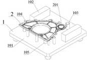
图1是本发明实施例中O型密封油槽的高度检测装置的定位组件结构示意图;1 is a schematic structural diagram of a positioning assembly of a height detection device for an O-shaped sealed oil tank in an embodiment of the present invention;
图2是本发明实施例中O型密封油槽的高度检测装置的定位组件结构侧视图;2 is a side view of the structure of the positioning assembly of the height detection device of the O-shaped sealed oil groove in the embodiment of the present invention;
图3是本发明实施例中O型密封油槽的高度检测装置的测量组件结构示意图;3 is a schematic structural diagram of a measuring assembly of a height detection device for an O-shaped sealed oil tank in an embodiment of the present invention;
图4是本发明实施例中待检测工件在定位组件上定位放置示意图;4 is a schematic diagram of positioning and placing a workpiece to be detected on a positioning assembly in an embodiment of the present invention;
在所有附图中,同样的附图标记表示相同的技术特征,具体为:In all drawings, the same reference numerals represent the same technical features, specifically:
1、定位组件;2、工件;3、测量组件;1. Positioning component; 2. Workpiece; 3. Measuring component;
101、底板;102、等高块;103、标准柱;104、限位柱;105、支撑柱;106、定位销;201、O型密封油槽;301、表座;302、百分表;303、调节锁定件;304、把手。101, bottom plate; 102, contour block; 103, standard column; 104, limit column; 105, support column; 106, positioning pin; 201, O-type sealing oil groove; 301, watch seat; 302, dial indicator; 303 , adjusting the locking piece; 304, the handle.
具体实施方式Detailed ways
为了使本发明的目的、技术方案及优点更加清楚明白,以下结合附图及实施例,对本发明进行进一步详细说明。应当理解,此处所描述的具体实施例仅用以解释本发明,并不用于限定本发明。此外,下面所描述的本发明各个实施方式中所涉及到的技术特征只要彼此之间未构成冲突就可以相互组合。In order to make the objectives, technical solutions and advantages of the present invention clearer, the present invention will be further described in detail below with reference to the accompanying drawings and embodiments. It should be understood that the specific embodiments described herein are only used to explain the present invention, but not to limit the present invention. In addition, the technical features involved in the various embodiments of the present invention described below can be combined with each other as long as they do not conflict with each other.
在本发明的描述中,需要理解的是,术语“中心”、“纵向”、“横向”、“长度”、“宽度”、“厚度”、“上”、“下”、“前”、“后”、“左”、“右”、“竖直”、“水平”、“顶”、“底”、“内”、“外”、“顺时针”、“逆时针”、“轴向”、“径向”、“周向”等指示的方位或位置关系为基于附图所示的方位或位置关系,仅是为了便于描述本发明和简化描述,而不是指示或暗示所指的装置或元件必须具有特定的方位、以特定的方位构造和操作,因此不能理解为对本发明的限制。In the description of the present invention, it should be understood that the terms "center", "longitudinal", "lateral", "length", "width", "thickness", "upper", "lower", "front", " Back, Left, Right, Vertical, Horizontal, Top, Bottom, Inner, Outer, Clockwise, Counterclockwise, Axial , "radial", "circumferential" and other indicated orientations or positional relationships are based on the orientations or positional relationships shown in the accompanying drawings, and are only for the convenience of describing the present invention and simplifying the description, rather than indicating or implying the indicated device or Elements must have a particular orientation, be constructed and operate in a particular orientation and are therefore not to be construed as limitations of the invention.
此外,术语“第一”、“第二”仅用于描述目的,而不能理解为指示或暗示相对重要性或者隐含指明所指示的技术特征的数量。由此,限定有“第一”、“第二”的特征可以明示或者隐含地包括至少一个该特征。在本发明的描述中,“多个”的含义是至少两个,例如两个,三个等,除非另有明确具体的限定。In addition, the terms "first" and "second" are only used for descriptive purposes, and should not be construed as indicating or implying relative importance or implying the number of indicated technical features. Thus, a feature delimited with "first", "second" may expressly or implicitly include at least one of that feature. In the description of the present invention, "plurality" means at least two, such as two, three, etc., unless otherwise expressly and specifically defined.
在本发明中,除非另有明确的规定和限定,术语“安装”、“相连”、“连接”、“固定”等术语应做广义理解,例如,可以是固定连接,也可以是可拆卸连接,或成一体;可以是机械连接,也可以是电连接;可以是直接相连,也可以通过中间媒介间接相连,可以是两个元件内部的连通或两个元件的相互作用关系,除非另有明确的限定。对于本领域的普通技术人员而言,可以根据具体情况理解上述术语在本发明中的具体含义。In the present invention, unless otherwise expressly specified and limited, the terms "installed", "connected", "connected", "fixed" and other terms should be understood in a broad sense, for example, it may be a fixed connection or a detachable connection , or integrated; it can be a mechanical connection or an electrical connection; it can be directly connected or indirectly connected through an intermediate medium, it can be the internal connection of two elements or the interaction relationship between the two elements, unless otherwise specified limit. For those of ordinary skill in the art, the specific meanings of the above terms in the present invention can be understood according to specific situations.
在本发明中,除非另有明确的规定和限定,第一特征在第二特征“上”或“下”可以是第一和第二特征直接接触,或第一和第二特征通过中间媒介间接接触。而且,第一特征在第二特征“之上”、“上方”和“上面”可是第一特征在第二特征正上方或斜上方,或仅仅表示第一特征水平高度高于第二特征。第一特征在第二特征“之下”、“下方”和“下面”可以是第一特征在第二特征正下方或斜下方,或仅仅表示第一特征水平高度小于第二特征。In the present invention, unless otherwise expressly specified and limited, a first feature "on" or "under" a second feature may be in direct contact between the first and second features, or the first and second features indirectly through an intermediary touch. Also, the first feature being "above", "over" and "above" the second feature may mean that the first feature is directly above or obliquely above the second feature, or simply means that the first feature is level higher than the second feature. The first feature being "below", "below" and "below" the second feature may mean that the first feature is directly below or obliquely below the second feature, or simply means that the first feature has a lower level than the second feature.
实施例:Example:
请参阅图1~图4,本发明优选实施例中的O型密封油槽的高度检测装置包括定位组件1和测量组件3,由定位组件1完成工件2的定位,也即是实现O型密封油槽201的定位。之后,通过测量组件3在定位组件1上的定位放置,实现测量组件3与O型密封油槽201的定位和测量。Please refer to FIGS. 1 to 4 , the height detection device of the O-shaped sealed oil groove in the preferred embodiment of the present invention includes a
具体而言,优选实施例中的定位组件1如图1中所示,其包括呈板状结构的底板101,该底板101的一端为工件定位端,其顶面上设置有多个销柱结构,用于实现工件2的定位和限位;相应地,底板101的另一端为测具定位端,其顶面上成对设置有等高块102,两等高块102进一步优选平行间隔设置在底板101顶面上的横向两侧,用于测量组件3的放置和定位。实际设置时,等高块102自测具定位端延伸至工件定位端的销柱结构两侧,使得工件2对应定位后,其O型密封油槽201可以位于两等高块102之间。Specifically, as shown in FIG. 1 , the
更详细地,优选实施例中的销柱结构包括至少3个支撑柱105,用于支撑工件2的底部;优选地,优选实施例中的支撑柱105为如图1中所示的间隔设置的3个,分别用于支撑工件2的三角。同时,在支撑柱105的外侧设置有多个限位柱104,例如图1中间隔设置的5个,用于对工件2的外周侧壁面进行抵接限位,防止工件2在检测过程中发生偏移,保证检测过程的准确性。实际实质是,各支撑柱105设置在多个限位柱104所围区域的内侧,以此保证支撑柱105对工件2的可靠支撑以及限位柱104对工件2的准确限位。In more detail, the pin structure in the preferred embodiment includes at least three
相应地,对应工件2上的定位孔设置有定位销106,如图1中所示的两个,用于从底部嵌入工件2上的定位孔中,对工件2的位置进行进一步地定位。Correspondingly, the positioning holes on the
此外,为了实现测量组件3在测量时的校准,在两等高块102之间设置有至少一处标准柱103,其设置在底板101上后,顶面距底板101顶面、距等高块102的顶面的距离为已知的固定值,以此来实现测量组件3测量前的校准,保证测量结果的准确性。In addition, in order to realize the calibration of the measuring
显然,不难理解的是,优选实施例中标准柱103的设置位置处于销柱结构的最外侧,确保工件2限位放置于销柱结构上后,标准柱103位于不被工件2所遮挡的位置,如图4中所示。Obviously, it is not difficult to understand that in the preferred embodiment, the setting position of the
进一步地,对于优选实施例中的销柱结构而言,其高度形式如图2中所示。其中,支撑柱105在底板101上设置后的竖向尺寸L1小于限位柱104的竖向尺寸,使得工件2在支撑柱105上设置后,限位柱104的顶部可突出工件2的底面。同时,标准柱103的竖向尺寸L2不小于支撑柱105的竖向尺寸,并使得工件2在定位组件1上设置后其O型密封油槽201的底部高度大于标准柱103的竖向高度。当然,显而易见地,标准柱103的竖向尺寸低于两等高块102的竖向尺寸L3。另外,位于两等高块102之间的限位柱104的高度也不大于等高块102的高度,以此避免发生干涉。Further, for the pin structure in the preferred embodiment, its height form is as shown in FIG. 2 . The vertical dimension L1of the
如图3中所示,优选实施例中的测量组件3如图3中所示,其包括呈长条形块状结构的表座301,其长度不小于两等高块102之间的距离,使得表座301的两端可对应搭放在两等高块102上。同时,优选实施例中的表座301为耐变形和耐磨损的金属块结构,其重量较大,以此来保证其两端放置于两等高块102上工作时的稳定性,避免测量过程中表座301的端部抬起,为百分表302的测量提供可靠的基准。As shown in FIG. 3 , the
在优选实施例中,对应百分表302的设置,在表座301的顶部开设有竖向通孔,用于百分表302底部套筒的穿过;相应地,在表座301的侧壁上开设有连通竖向通孔的横向通孔,用于调节锁定件303的匹配设置,使得调节锁定件303的端部可以穿过横向通孔,并抵接匹配在百分表302套筒的外周,以此实现百分表302在表座301上的定位和锁定。同时,通过松开调节锁定件303,可以实现套筒在竖向上的往复移动,进而调整百分表302底部表针的竖向位置,满足不同高度O型密封油槽201的测量需求。In the preferred embodiment, corresponding to the setting of the
优选地,在表座301的至少一端的端部设置有把手304,用于操作人员进行手持抬放,如此,便不需要将整个表座301拿起,便可实现测量组件3测量位置的更换,可以极大地减少测量人员的工作强度,提升O型密封油槽201中多点位测量的效率。Preferably, a
进一步优选地,在底板101的底部还间隔设置有多个支脚,如图2中所示,用于支撑底板101进行工作。在实际设置时,部分或者全部支脚为竖向高度可调的形式,以此可以实现底板101在不同工作环境下的水平调整。Further preferably, at the bottom of the
对于优选实施例中O型密封油槽201的高度检测装置而言,利用其对工件2的O型密封油槽201进行高度检测的方法优选包括如下过程:For the height detection device for the O-shaped sealing
(1)将待检产品放置在底板101上的销柱结构上,使得设置有O型密封油槽201的一侧朝上并伸入两等高块102之间,如图4中所示。其中,由支撑柱105对工件2的各位置底部进行支撑,并由定位销106对应嵌设于工件2上的定位孔中,完成工件2的定位,相应地,工件2的外周由多个限位柱104进行限位,保证工件2不发生横向位移。(1) Place the product to be inspected on the pin structure on the
(2)将测量组件3放置在两等高块102上,使得百分表302的表针朝下;此后,将百分表302挪动到标准柱103的正上方,并由标准柱103对百分表302进行标定校准,使得表针刚好抵接标准柱103顶面时为测定的零位;相应地,控制调节锁定件303将百分表锁定在位。(2) Place the measuring
(3)移动测量组件3,使得百分表302移动到待测量O型密封油槽201的正上方,使得百分表302的表针可以对应抵接在待测量O型密封油槽201的底面;此时,通过百分表302读出O型密封油槽201的第一个测值并记录。(3) Move the measuring
(4)手持把手304,将表座301的一端抬起,改变表针在O型密封油槽201中的位置,再将表座301放下,读出另一个测值,以此类推,获得O型密封油槽201中的多个测值,实现O型密封油槽201单点高度和平面高度的精确检测。(4) Holding the
(5)待完成一个工件2的检测后,手持把手304将表座301抬离O型密封油槽201,便可将完成检测的工件2从底板101上取下,更换下一个工件之后,重复步骤(3)、(4)中的过程,便可完成另一个工件2的O型密封油槽201的高度检测。(5) After the detection of one
本发明中的O型密封油槽的高度检测装置,其结构简单,操作简便,能够实现铸件O型密封油槽高度的批量检测,整个检测过程无需过多的人力动作,能够大幅提升检测的效率,减少因人力动作不一致引入的测量误差,满足工件的批量检测需求,降低工件的检测成本和加工成本,具有较好的实用价值和应用前景。The height detection device of the O-shaped sealing oil groove in the present invention has the advantages of simple structure and simple operation, and can realize batch detection of the height of the O-shaped sealing oil groove of the casting. The measurement error introduced by inconsistent human actions can meet the needs of batch inspection of workpieces, reduce the inspection cost and processing cost of workpieces, and has good practical value and application prospects.
本领域的技术人员容易理解,以上所述仅为本发明的较佳实施例而已,并不用以限制本发明,凡在本发明的精神和原则之内所作的任何修改、等同替换和改进等,均应包含在本发明的保护范围之内。Those skilled in the art can easily understand that the above are only preferred embodiments of the present invention, and are not intended to limit the present invention. Any modifications, equivalent replacements and improvements made within the spirit and principles of the present invention, etc., All should be included within the protection scope of the present invention.
Claims (9)
Priority Applications (1)
| Application Number | Priority Date | Filing Date | Title |
|---|---|---|---|
| CN202210569382.4ACN114963935A (en) | 2022-05-24 | 2022-05-24 | Height detection device and detection method for O-shaped sealing oil groove |
Applications Claiming Priority (1)
| Application Number | Priority Date | Filing Date | Title |
|---|---|---|---|
| CN202210569382.4ACN114963935A (en) | 2022-05-24 | 2022-05-24 | Height detection device and detection method for O-shaped sealing oil groove |
Publications (1)
| Publication Number | Publication Date |
|---|---|
| CN114963935Atrue CN114963935A (en) | 2022-08-30 |
Family
ID=82971880
Family Applications (1)
| Application Number | Title | Priority Date | Filing Date |
|---|---|---|---|
| CN202210569382.4APendingCN114963935A (en) | 2022-05-24 | 2022-05-24 | Height detection device and detection method for O-shaped sealing oil groove |
Country Status (1)
| Country | Link |
|---|---|
| CN (1) | CN114963935A (en) |
Citations (3)
| Publication number | Priority date | Publication date | Assignee | Title |
|---|---|---|---|---|
| CN206073900U (en)* | 2016-10-19 | 2017-04-05 | 广东鸿图武汉压铸有限公司 | A kind of cast blank flatness checking device of back of the body mode centering machining benchmark |
| CN208333313U (en)* | 2018-07-06 | 2019-01-04 | 无锡市海峰海林精密轴承有限公司 | A kind of device for the measurement of Oscillating lever bearing ditch position |
| CN113188409A (en)* | 2021-04-23 | 2021-07-30 | 广东鸿图武汉压铸有限公司 | Dimension detection device and dimension detection method for O-shaped groove in straight hole |
- 2022
- 2022-05-24CNCN202210569382.4Apatent/CN114963935A/enactivePending
Patent Citations (3)
| Publication number | Priority date | Publication date | Assignee | Title |
|---|---|---|---|---|
| CN206073900U (en)* | 2016-10-19 | 2017-04-05 | 广东鸿图武汉压铸有限公司 | A kind of cast blank flatness checking device of back of the body mode centering machining benchmark |
| CN208333313U (en)* | 2018-07-06 | 2019-01-04 | 无锡市海峰海林精密轴承有限公司 | A kind of device for the measurement of Oscillating lever bearing ditch position |
| CN113188409A (en)* | 2021-04-23 | 2021-07-30 | 广东鸿图武汉压铸有限公司 | Dimension detection device and dimension detection method for O-shaped groove in straight hole |
Similar Documents
| Publication | Publication Date | Title |
|---|---|---|
| CN109839047B (en) | Part surface hole position and center distance size detection tool | |
| CN102506632A (en) | Device for measuring taper hole | |
| CN110160464B (en) | Device for measuring cylindricity of inner hole and application method thereof | |
| CN201247031Y (en) | End-face annular and trapezoid slots detection measuring tool | |
| CN209820370U (en) | Flange cover depth gauge | |
| CN106197201A (en) | Position detecting tool | |
| CN202329460U (en) | Taper hole measurement device | |
| CN114963935A (en) | Height detection device and detection method for O-shaped sealing oil groove | |
| CN211317140U (en) | Deep hole step height measuring device | |
| CN105157639B (en) | Combined positioning device and positioning method | |
| CN110836624A (en) | Inner and outer seam allowance measuring tool for disc ring type parts and using method thereof | |
| CN110285743A (en) | Checking fixture and testing method for measuring the groove width of the inner ring ring and the distance between the relative outer shoulders | |
| CN215725522U (en) | Quick detection device for positioning groove of input shaft of automobile steering device | |
| CN212458217U (en) | Special detection tool for depth of engine cylinder sleeve seat | |
| CN211651463U (en) | High-precision detection device for measuring outer diameter | |
| CN216205995U (en) | Self-centering hole position and groove size measuring device | |
| CN220556302U (en) | Detection measuring tool | |
| CN108534647B (en) | Inspection tool for detecting part errors and method of using the same | |
| CN203534468U (en) | Detection device for disk groove center distance dimension | |
| CN222799914U (en) | A high-precision flatness detection fixture | |
| CN204854599U (en) | Offset measuring apparatu | |
| CN222635357U (en) | Comprehensive size detection device | |
| CN220853362U (en) | Roundness detection device for disc sleeve type parts | |
| CN219798145U (en) | Motor shaft boss face size detection tool | |
| CN205066723U (en) | Combined positioning device |
Legal Events
| Date | Code | Title | Description |
|---|---|---|---|
| PB01 | Publication | ||
| PB01 | Publication | ||
| SE01 | Entry into force of request for substantive examination | ||
| SE01 | Entry into force of request for substantive examination |