CN114951970A - System and method for laser welding a workpiece with a laser beam that uses multiple reflective components to reach inaccessible areas of the workpiece - Google Patents
System and method for laser welding a workpiece with a laser beam that uses multiple reflective components to reach inaccessible areas of the workpieceDownload PDFInfo
- Publication number
- CN114951970A CN114951970ACN202210155247.5ACN202210155247ACN114951970ACN 114951970 ACN114951970 ACN 114951970ACN 202210155247 ACN202210155247 ACN 202210155247ACN 114951970 ACN114951970 ACN 114951970A
- Authority
- CN
- China
- Prior art keywords
- workpiece
- laser beam
- laser
- assembly
- reflector
- Prior art date
- Legal status (The legal status is an assumption and is not a legal conclusion. Google has not performed a legal analysis and makes no representation as to the accuracy of the status listed.)
- Pending
Links
- 238000003466weldingMethods0.000titleclaimsabstractdescription49
- 238000000034methodMethods0.000titleclaimsabstractdescription14
- 230000003287optical effectEffects0.000claimsabstractdescription56
- 230000008859changeEffects0.000claimsabstractdescription11
- 230000004044responseEffects0.000claimsdescription2
- 238000004519manufacturing processMethods0.000description8
- 239000000463materialSubstances0.000description5
- 238000013459approachMethods0.000description4
- 230000008901benefitEffects0.000description4
- 238000013461designMethods0.000description3
- 238000010438heat treatmentMethods0.000description3
- 230000001154acute effectEffects0.000description2
- 239000011248coating agentSubstances0.000description2
- 238000000576coating methodMethods0.000description2
- 238000012377drug deliveryMethods0.000description2
- 230000000694effectsEffects0.000description2
- PCHJSUWPFVWCPO-UHFFFAOYSA-NgoldChemical compound[Au]PCHJSUWPFVWCPO-UHFFFAOYSA-N0.000description2
- 239000010931goldSubstances0.000description2
- 229910052737goldInorganic materials0.000description2
- 238000005286illuminationMethods0.000description2
- 239000004033plasticSubstances0.000description2
- 230000008569processEffects0.000description2
- 229920001169thermoplasticPolymers0.000description2
- 239000004416thermosoftening plasticSubstances0.000description2
- 230000009466transformationEffects0.000description2
- 238000006243chemical reactionMethods0.000description1
- 238000007796conventional methodMethods0.000description1
- 230000001419dependent effectEffects0.000description1
- 238000006073displacement reactionMethods0.000description1
- 239000003814drugSubstances0.000description1
- 229940079593drugDrugs0.000description1
- 238000005516engineering processMethods0.000description1
- 238000002474experimental methodMethods0.000description1
- 238000005304joiningMethods0.000description1
- 238000012423maintenanceMethods0.000description1
- 230000013011matingEffects0.000description1
- 238000005259measurementMethods0.000description1
- 230000007246mechanismEffects0.000description1
- 238000002844meltingMethods0.000description1
- 230000008018meltingEffects0.000description1
- 238000012986modificationMethods0.000description1
- 230000004048modificationEffects0.000description1
- 238000013021overheatingMethods0.000description1
- 230000005855radiationEffects0.000description1
- 230000008439repair processEffects0.000description1
- 238000000926separation methodMethods0.000description1
Images


Classifications
- B—PERFORMING OPERATIONS; TRANSPORTING
- B23—MACHINE TOOLS; METAL-WORKING NOT OTHERWISE PROVIDED FOR
- B23K—SOLDERING OR UNSOLDERING; WELDING; CLADDING OR PLATING BY SOLDERING OR WELDING; CUTTING BY APPLYING HEAT LOCALLY, e.g. FLAME CUTTING; WORKING BY LASER BEAM
- B23K26/00—Working by laser beam, e.g. welding, cutting or boring
- B23K26/02—Positioning or observing the workpiece, e.g. with respect to the point of impact; Aligning, aiming or focusing the laser beam
- B23K26/06—Shaping the laser beam, e.g. by masks or multi-focusing
- B23K26/0604—Shaping the laser beam, e.g. by masks or multi-focusing by a combination of beams
- B23K26/0619—Shaping the laser beam, e.g. by masks or multi-focusing by a combination of beams with spots located on opposed surfaces of the workpiece
- B—PERFORMING OPERATIONS; TRANSPORTING
- B23—MACHINE TOOLS; METAL-WORKING NOT OTHERWISE PROVIDED FOR
- B23K—SOLDERING OR UNSOLDERING; WELDING; CLADDING OR PLATING BY SOLDERING OR WELDING; CUTTING BY APPLYING HEAT LOCALLY, e.g. FLAME CUTTING; WORKING BY LASER BEAM
- B23K26/00—Working by laser beam, e.g. welding, cutting or boring
- B23K26/02—Positioning or observing the workpiece, e.g. with respect to the point of impact; Aligning, aiming or focusing the laser beam
- B23K26/06—Shaping the laser beam, e.g. by masks or multi-focusing
- B23K26/064—Shaping the laser beam, e.g. by masks or multi-focusing by means of optical elements, e.g. lenses, mirrors or prisms
- B23K26/0643—Shaping the laser beam, e.g. by masks or multi-focusing by means of optical elements, e.g. lenses, mirrors or prisms comprising mirrors
- B—PERFORMING OPERATIONS; TRANSPORTING
- B23—MACHINE TOOLS; METAL-WORKING NOT OTHERWISE PROVIDED FOR
- B23K—SOLDERING OR UNSOLDERING; WELDING; CLADDING OR PLATING BY SOLDERING OR WELDING; CUTTING BY APPLYING HEAT LOCALLY, e.g. FLAME CUTTING; WORKING BY LASER BEAM
- B23K26/00—Working by laser beam, e.g. welding, cutting or boring
- B23K26/02—Positioning or observing the workpiece, e.g. with respect to the point of impact; Aligning, aiming or focusing the laser beam
- B23K26/06—Shaping the laser beam, e.g. by masks or multi-focusing
- B23K26/064—Shaping the laser beam, e.g. by masks or multi-focusing by means of optical elements, e.g. lenses, mirrors or prisms
- B23K26/0652—Shaping the laser beam, e.g. by masks or multi-focusing by means of optical elements, e.g. lenses, mirrors or prisms comprising prisms
- B—PERFORMING OPERATIONS; TRANSPORTING
- B23—MACHINE TOOLS; METAL-WORKING NOT OTHERWISE PROVIDED FOR
- B23K—SOLDERING OR UNSOLDERING; WELDING; CLADDING OR PLATING BY SOLDERING OR WELDING; CUTTING BY APPLYING HEAT LOCALLY, e.g. FLAME CUTTING; WORKING BY LASER BEAM
- B23K26/00—Working by laser beam, e.g. welding, cutting or boring
- B23K26/08—Devices involving relative movement between laser beam and workpiece
- B23K26/082—Scanning systems, i.e. devices involving movement of the laser beam relative to the laser head
- B—PERFORMING OPERATIONS; TRANSPORTING
- B23—MACHINE TOOLS; METAL-WORKING NOT OTHERWISE PROVIDED FOR
- B23K—SOLDERING OR UNSOLDERING; WELDING; CLADDING OR PLATING BY SOLDERING OR WELDING; CUTTING BY APPLYING HEAT LOCALLY, e.g. FLAME CUTTING; WORKING BY LASER BEAM
- B23K26/00—Working by laser beam, e.g. welding, cutting or boring
- B23K26/20—Bonding
- B23K26/21—Bonding by welding
- B23K26/24—Seam welding
- B23K26/28—Seam welding of curved planar seams
- B23K26/282—Seam welding of curved planar seams of tube sections
- B—PERFORMING OPERATIONS; TRANSPORTING
- B23—MACHINE TOOLS; METAL-WORKING NOT OTHERWISE PROVIDED FOR
- B23K—SOLDERING OR UNSOLDERING; WELDING; CLADDING OR PLATING BY SOLDERING OR WELDING; CUTTING BY APPLYING HEAT LOCALLY, e.g. FLAME CUTTING; WORKING BY LASER BEAM
- B23K26/00—Working by laser beam, e.g. welding, cutting or boring
- B23K26/70—Auxiliary operations or equipment
- B—PERFORMING OPERATIONS; TRANSPORTING
- B23—MACHINE TOOLS; METAL-WORKING NOT OTHERWISE PROVIDED FOR
- B23K—SOLDERING OR UNSOLDERING; WELDING; CLADDING OR PLATING BY SOLDERING OR WELDING; CUTTING BY APPLYING HEAT LOCALLY, e.g. FLAME CUTTING; WORKING BY LASER BEAM
- B23K2101/00—Articles made by soldering, welding or cutting
- B23K2101/04—Tubular or hollow articles
- B23K2101/06—Tubes
- B—PERFORMING OPERATIONS; TRANSPORTING
- B23—MACHINE TOOLS; METAL-WORKING NOT OTHERWISE PROVIDED FOR
- B23K—SOLDERING OR UNSOLDERING; WELDING; CLADDING OR PLATING BY SOLDERING OR WELDING; CUTTING BY APPLYING HEAT LOCALLY, e.g. FLAME CUTTING; WORKING BY LASER BEAM
- B23K2103/00—Materials to be soldered, welded or cut
- B23K2103/30—Organic material
- B23K2103/42—Plastics
Landscapes
- Physics & Mathematics (AREA)
- Optics & Photonics (AREA)
- Engineering & Computer Science (AREA)
- Plasma & Fusion (AREA)
- Mechanical Engineering (AREA)
- Laser Beam Processing (AREA)
Abstract
Translated fromChinese
Description
Translated fromChinese相关申请的交叉引用CROSS-REFERENCE TO RELATED APPLICATIONS
本申请要求于2021年2月22日提交的第17/182,055号美国专利申请和于2021年3月29日提交的第17/215,520号美国专利申请的优先权,上述每个专利申请的全部公开内容通过引用并入本文中。This application claims priority to US Patent Application Serial No. 17/182,055, filed February 22, 2021, and US Patent Application Serial No. 17/215,520, filed March 29, 2021, the entire disclosures of each of the foregoing patent applications The contents are incorporated herein by reference.
技术领域technical field
本公开的方面大体上涉及激光焊接系统,并且更具体地,涉及用于使用激光束和具有多个光学反射表面的单个的固定光学反射器来焊接管状元件的系统和方法。Aspects of the present disclosure relate generally to laser welding systems, and more particularly, to systems and methods for welding tubular elements using a laser beam and a single fixed optical reflector having multiple optically reflective surfaces.
背景技术Background technique
大多数药物输送设备包括连接该设备的不同部件的塑料管,并且药物通过那些塑料管被输送给患者。各种管状元件之间的接头(诸如,管到端口或管到管类型)是最常见的子组件之一,并且可以在大多数药物输送设备中被找到。Most drug delivery devices include plastic tubes that connect the different parts of the device, and the drug is delivered to the patient through those plastic tubes. Joints between various tubular elements, such as tube-to-port or tube-to-tube types, are one of the most common subassemblies and can be found in most drug delivery devices.
激光焊接工艺是目前最先进的组装技术,并且对于大批量制造具有许多已证明的益处。然而,利用激光焊接工艺将管状元件自身之间连接和将管状元件连接至其它部件存在技术挑战,因为这需要围绕配合表面360°环缝焊接(circumferential weld)。由于围绕组件旋转激光源或者在静止的激光头下转动组件(该组件可以具有附接至其的容器或其它元件)对于制造工艺并不总是可行的,因此已经提出了多种方法来解决这种挑战。The laser welding process is the state-of-the-art assembly technology and has many proven benefits for high volume manufacturing. However, using a laser welding process to connect the tubular elements to themselves and to other components presents technical challenges as this requires a 360° circumferential weld around the mating surfaces. Since rotating the laser source around the assembly or rotating the assembly under a stationary laser head (the assembly may have a container or other element attached to it) is not always feasible for the manufacturing process, various approaches have been proposed to address this problem. kind of challenge.
例如,管状工件可以纵向地设置在围绕工件的凹面圆形反射镜的中心处。然后,激光束围绕工件上方的反射镜旋转或环绕,引导激光束围绕工件的整个周向的外表面。这种传统的技术不适用于制造环境,因为通过圆形反射镜的中心操作工件是非常困难和繁重的,特别是在高产量环境中。For example, a tubular workpiece may be positioned longitudinally at the center of a concave circular mirror surrounding the workpiece. The laser beam then rotates or wraps around a mirror above the workpiece, directing the laser beam around the entire circumferential outer surface of the workpiece. This traditional technique is not suitable for a manufacturing environment because it is very difficult and burdensome to maneuver the workpiece through the center of a circular mirror, especially in a high-volume environment.
作为另一示例,使用一组复杂的光学反射器将激光束重定向到工件的相对侧上。使用多个凹面反射镜和平坦的反射镜(诸如,圆锥反射镜、球面反射镜和平面反射镜)的组合,以在焊接期间使激光束朝向工件的相对侧和横向侧偏转。然而,这种错综复杂的光学系统非常昂贵并且在维护期间难以修复。As another example, a complex set of optical reflectors is used to redirect the laser beam onto opposite sides of the workpiece. A combination of multiple concave mirrors and flat mirrors, such as conical mirrors, spherical mirrors, and planar mirrors, are used to deflect the laser beam toward opposite and lateral sides of the workpiece during welding. However, such intricate optical systems are very expensive and difficult to repair during maintenance.
第20170182592A1号美国专利申请公开中提出了另一常规方法,其描述了位于管状组件下方的一对可调整的光学反射器,该光学反射器的角度以及横向位置和竖直位置可以调整,因此从这些反射器反射的光束可以覆盖组件的底部的两侧,同时组件的上部暴露在直射光束下,直射光束在横向方向上扫描组件。这种方法的阐明的目的是提供“更简单、更节省空间的技术”。然而,为了使反射光束均匀地加热组件的整个底部,并引起材料的均匀熔化,这种方法需要对每对反射器进行耗时的调整,以找到两个反射器相对于组件的正确角度以及横向位置和竖直位置。Another conventional approach is proposed in US Patent Application Publication No. 20170182592A1, which describes a pair of adjustable optical reflectors located below the tubular assembly, the angle of the optical reflectors as well as the lateral and vertical positions can be adjusted, thus from The beams reflected by these reflectors can cover both sides of the bottom of the module, while the upper part of the module is exposed to a direct beam that scans the module in a lateral direction. The purpose of the elucidation of this method is to provide "simpler, more space-saving techniques". However, in order for the reflected beam to uniformly heat the entire bottom of the assembly and cause uniform melting of the material, this approach requires time-consuming adjustments to each pair of reflectors to find the correct angle of both reflectors relative to the assembly and the lateral position and vertical position.
如果两个反射器之间的角度或它们的横向位置或垂直位置不正确,则这个误差将导致底部(工件)的不同部分的不均匀加热。例如,反射器之间的较宽角度或两个反射器的基座与组件的位置之间的在Z轴(相对于地面竖直)上的较大距离将导致工件部件的最底部过热和其侧部欠热。反射器之间较大的横向距离、较小的角度或较短的Z轴间隔将导致组件的底部的侧部过热以及底部(最下部分)的中心欠热,这将导致该位置处的不充分加热和潜在泄漏路径。为了均匀地加热组件中工件的底部的两侧,Z轴(竖直)与两个反射器的表面之间的角度需要完全相同,并且虽然调整一个反射器的角度位置是容易的,但是测量固定装置中反射器之间的角度是非常麻烦、耗时且具有挑战性的。由于这种调整需要迭代多次,以找到与组件的特定位置相对应的正确角度并确保两个反射器的位置相同。两个反射器相对于彼此需要进行精确角度对准,这明显地增加了设置的难度。If the angle between the two reflectors or their lateral or vertical position is incorrect, this error will result in uneven heating of different parts of the base (workpiece). For example, a wider angle between the reflectors or a larger distance on the Z-axis (vertical to the ground) between the bases of the two reflectors and the position of the assembly will cause the bottommost part of the workpiece to overheat and its The side is underheated. Larger lateral distances, smaller angles, or shorter Z-axis separation between reflectors will result in overheating of the sides of the bottom of the assembly and underheating of the center of the bottom (lowermost) portion, which will cause inconsistencies at that location. Adequate heating and potential leak paths. In order to uniformly heat both sides of the bottom of the workpiece in the assembly, the angle between the Z axis (vertical) and the surfaces of the two reflectors needs to be exactly the same, and while it is easy to adjust the angular position of one reflector, the measurement is fixed The angle between the reflectors in the device is very cumbersome, time consuming and challenging. Since this adjustment requires multiple iterations to find the correct angle that corresponds to the specific position of the component and ensure that both reflectors are in the same position. The need for precise angular alignment of the two reflectors with respect to each other significantly increases the difficulty of the setup.
换句话说,第20170182592A1号美国专利申请公开中提出的方法由于必须对每个工件部件的组件的多个操作元件进行多种调整组合而因此非常容易导致设置误差或延长设置时间。In other words, the method proposed in US Patent Application Publication No. 20170182592A1 is very likely to cause setup errors or prolong setup time due to the necessity to perform various adjustment combinations for the plurality of operating elements of the assembly of each workpiece part.
还需要一种装置,其中激光可以到达工件的不在激光的直接路径上的区域。例如,除非工件被转动或激光器被移动,否则直接在激光后面的工件的区域不能被能量接近,这需要仔细的校准和移动协调以及庞大的设置,这将难以应用于多种工件类型和形状因素。There is also a need for a device in which the laser can reach areas of the workpiece that are not in the direct path of the laser. For example, unless the workpiece is turned or the laser is moved, the area of the workpiece directly behind the laser cannot be accessed by the energy, which requires careful alignment and movement coordination and bulky setups that would be difficult to apply to multiple workpiece types and form factors .
因此,需要用于更精确地激光焊接管状元件的系统和方法,该系统和方法产生更加一致且更高质量的焊接结果,而不需要在高产量制造环境中在焊接之前对组件进行大量的、容易出错或耗时的预调整或校准。Accordingly, there is a need for a system and method for more precise laser welding of tubular components that produces more consistent and higher quality weld results without requiring extensive, extensive, pre-welding of the components in a high-throughput manufacturing environment. Error-prone or time-consuming pre-adjustments or calibrations.
发明内容SUMMARY OF THE INVENTION
本发明的方面反映了对第20170182592A1号美国专利申请公开中所阐述的公开内容的改进。一个关键区别在于,本公开建议使用具有相对于彼此成钝角(大于90度且小于180度)的多个光学反射侧表面(配置为反射激光束)的单个的、单一的、固定的光学反射器代替使用一对光学反射器。另一关键区别在于,焊接组件所需的唯一预焊接设置是在开始激光焊接之前工件相对于光学反射器的Z轴(竖直方向)调整。不需要相对于工件调整反射表面相对于彼此的相应横向位置或角度。实际上,因为本公开的光学反射器是固定的单一件,所以甚至不可能进行这种调整。因此,无论是在设备的设置期间进行预焊接,还是在将激光能量传递给工件的焊接期间,光学反射器始终保持固定。此外,激光源在焊接期间不需要围绕工件旋转,而是在设置期间预焊接和焊接期间相对于工件保持固定距离。这些方面在需要最小化设置时间的高产量环境中,进行具有高重复性和非常低的可变性、以及非常少的设置时间和工作量(仅调整工件与光学反射器的底部或中心之间的竖直距离)的一致地高质量360度环缝焊接,但是在制造工艺期间焊接相同的部件的同时,从部件到部件的焊接必须是一致的且高质量的,而不需要对设置进行微调整。本公开促进了用于管状部件(工件)的环缝焊接的激光焊接设置的“设置并忘记它”配置,在对相同部件开始焊接之前的设置期间仅需要一次调整,而不需要在高产量环境中对相同部件进行任何进一步的调整。不仅总体上改善了焊接质量并且从部件到部件显著地一致,而且由于快速的设置时间(组件的一个部件的竖直调整)以及一旦设置完成无需任何调整,生产量显著增加。Aspects of the present invention reflect improvements over the disclosure set forth in US Patent Application Publication No. 20170182592A1. One key difference is that the present disclosure proposes the use of a single, single, fixed optical reflector with multiple optically reflective side surfaces (configured to reflect the laser beam) at obtuse angles (greater than 90 degrees and less than 180 degrees) relative to each other Instead use a pair of optical reflectors. Another key difference is that the only pre-weld setup required to weld the assembly is the Z-axis (vertical) adjustment of the workpiece relative to the optical reflector before starting the laser welding. The respective lateral positions or angles of the reflective surfaces relative to each other need not be adjusted relative to the workpiece. In fact, since the optical reflector of the present disclosure is a fixed single piece, this adjustment is not even possible. Therefore, the optical reflector remains stationary, whether during pre-welding during the setup of the device or during welding where the laser energy is transferred to the workpiece. Furthermore, the laser source does not need to rotate around the workpiece during welding, but maintains a fixed distance relative to the workpiece during pre-welding during setup and during welding. These aspects are performed with high repeatability and very low variability, as well as very little setup time and effort (just adjusting the distance between the workpiece and the bottom or center of the optical reflector) in a high-throughput environment where setup time needs to be minimized. Consistent high-quality 360-degree girth welds for vertical distances), but while welding the same parts during the manufacturing process, the welds must be consistent and high-quality from part to part without the need for fine-tuning settings . The present disclosure facilitates a "set it and forget it" configuration of laser welding setups for circumferential seam welding of tubular parts (workpieces), requiring only one adjustment during setup prior to starting welding on the same part, and not in high production environments make any further adjustments to the same parts. Not only is the weld quality improved overall and significantly consistent from part to part, but throughput is significantly increased due to fast setup times (vertical adjustment of one part of the assembly) and no adjustment required once setup is complete.
提供了一种用于围绕工件的全部或大部分周界进行焊接的激光焊接系统。系统包括:激光束源,配置成引导激光束;以及组件,组件包括第一成角度的反射器和光学反射器组件,第一成角度的反射器以固定的角度布置以改变激光束的方向,使得激光束照射工件的前部区域,光学反射器组件具有至少两个成角度的反射镜,至少两个成角度的反射镜定位成引导围绕工件经过的激光束以到达工件的不直接处于激光束的路径中的区域。第一成角度的反射器可以相对于激光束成45度角,使得激光束相对于其从激光束源发出的方向正交地改变方向。至少两个成角度的反射镜可以包括第一反射镜和第二反射镜。第一反射镜和第二反射镜可以布置在光学反射器组件的弯曲表面上,使得它们将激光束的方向改变45度,从而允许激光束到达工件的不直接在激光束的路径中的区域。激光束源可以被固定,并且当激光束被提供给工件时,工件可以相对于组件被固定。工件可以在要产生焊接的区域处具有大致圆柱形的截面。激光束可以响应于其被第一成角度的反射器和光学反射器组件改变的方向而到达工件的整个周界。光学反射器组件可以包括第三反射镜,第三反射镜定位成朝向工件的区域改变激光束的至少一部分的方向,工件的区域不直接处于激光束在被第一成角度的反射器反射之后的路径中。A laser welding system is provided for welding around all or most of the perimeter of a workpiece. The system includes: a laser beam source configured to direct the laser beam; and an assembly including a first angled reflector and an optical reflector assembly, the first angled reflector arranged at a fixed angle to change the direction of the laser beam, such that the laser beam illuminates a front area of the workpiece, the optical reflector assembly has at least two angled mirrors positioned to direct the laser beam passing around the workpiece to reach parts of the workpiece that are not directly in the laser beam area in the path. The first angled reflector may be angled at 45 degrees with respect to the laser beam such that the laser beam changes direction orthogonally with respect to the direction from which it emanates from the laser beam source. The at least two angled mirrors may include a first mirror and a second mirror. The first and second mirrors may be arranged on the curved surface of the optical reflector assembly such that they redirect the laser beam by 45 degrees, allowing the laser beam to reach areas of the workpiece that are not directly in the path of the laser beam. The laser beam source may be fixed, and the workpiece may be fixed relative to the assembly when the laser beam is provided to the workpiece. The workpiece may have a generally cylindrical cross-section at the region where the weld is to be produced. The laser beam may reach the entire perimeter of the workpiece in response to its direction being changed by the first angled reflector and optical reflector assembly. The optical reflector assembly may include a third mirror positioned to redirect at least a portion of the laser beam toward an area of the workpiece that is not directly where the laser beam is after being reflected by the first angled reflector in the path.
附图说明Description of drawings
根据以下优选的实施方式的描述并参考附图,将更好地理解本发明,在附图中:The invention will be better understood from the following description of preferred embodiments and with reference to the accompanying drawings, in which:
图1是示例性激光器组件和具有固定的U形光学反射器的工件组件,其中,固定的U形光学反射器具有以钝角固定的静止反射表面;1 is an exemplary laser assembly and workpiece assembly with a fixed U-shaped optical reflector having a stationary reflective surface fixed at an obtuse angle;
图2是图1所示的工件组件的立体图;Figure 2 is a perspective view of the workpiece assembly shown in Figure 1;
图3是使用根据本公开的光学反射器实现的激光焊接的示例性照片;3 is an exemplary photograph of laser welding achieved using an optical reflector according to the present disclosure;
图4是使用根据本公开的光学反射器实现的激光焊接的另一示例照片;4 is another example photograph of laser welding achieved using an optical reflector according to the present disclosure;
图5是工件与光学反射器的顶表面的底部或最低点之间的可调整的竖直距离的立体图;5 is a perspective view of the adjustable vertical distance between the workpiece and the bottom or nadir of the top surface of the optical reflector;
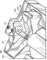
图6A是示例性激光器组件和具有光学反射器的工件组件的立体图,光学反射器布置成沿与激光束方向正交的方向照射工件,工件包括激光器的直接路径后面的区域;以及6A is a perspective view of an exemplary laser assembly and a workpiece assembly having an optical reflector arranged to illuminate the workpiece in a direction orthogonal to the direction of the laser beam, the workpiece including an area behind the direct path of the laser; and
图6B是具有标签的示例性激光器组件的立体图,以示出当激光穿过第一光学反射器并且然后穿过两个成角度的反射器时激光的示例性行进路径,以在工件周围产生环缝焊接。6B is a perspective view of an exemplary laser assembly with a label to illustrate an exemplary travel path of the laser light as it passes through a first optical reflector and then through two angled reflectors to create a ring around a workpiece Seam welding.
具体实施方式Detailed ways
图1所示的激光器组件200包括常规的激光源210,激光源210产生辐射的激光束120。安装件212a联接到正交的机架214a和214b。扫描头212内的一个或多个扫描反射镜由处理器控制的驱动单元213控制,以将激光束120向下引导到包括热塑性工件110的组件250上,其中,热塑性工件110具有将通过焊接连接的管状部件。驱动单元213被控制以调整扫描镜的位置,以照射固定在组件110内的工件110的顶表面上的规定的焊接区域所需的方式移动激光束120。The
基于该实验,已经确定,与传统方法相比,使用具有彼此固定成约110度至135度(例如,正或负15%)的两个平坦的侧表面262a、262b和从端部到端部264a、264b的连续反射表面的、单个的单一V形或U形反射器260允许大大简化与光学反射器260的侧部262a和262b等距放置的管状工件110的设置,并且将所需的设置工作量限制为仅竖直调整(Z轴)部件位置。将工件110和光学反射器260移动得更靠近在一起(减小图5中标记的距离D)允许将更多的激光能量从激光源210引导到工件部件110的最底部,而使工件110和光学反射器260移动得更远离(沿着Z轴或或增大图5中所示的距离D)增加了对工件110的下部分的侧部的照明。一旦找到提供部件的底部分的均匀照明的Z值,工件110和光学反射器260被锁定到该Z值距离D(图5),并且设置完成。通过位于组件250上方的焊接头212在横向方向上(没有旋转,参见图1中标记的X轴和/或Y轴)用激光束120扫描工件110将通过直接暴露于激光束120来照射工件110的上部分,并将通过由V形或U形反射器260反射的激光束120照射工件110的底部分,因此允许围绕管状工件110进行360°环缝焊接。Based on this experiment, it has been determined that using two
光学反射器260的光学反射表面262a、262b可以是配置为反射接收的激光能量120的镀金反射镜。表面262a、262b的角度将激光能量120引导到工件110的不能被固定在工件110上方的激光束120直接到达的表面中。焊接领域的普通技术人员将理解,不一定要整个表面262a、262b都涂覆有光学反射材料。实际上,用金或其它光学反射材料镀覆光学反射器260的整个表面是方便的,但是,当然只有光学反射器260的将要引导激光束120的表面部分需要具有光学反射材料。其它部分不一定要进行光学反射,诸如,工件110正下方的将不接收激光能量的底部或最低部分270(在图2和图5中最佳可见)。工件110正下面的部分270(图2)接收从光学反射器260的光学反射表面262a、262b反射的反射激光能量。这一切就是说,本领域的技术人员将会理解,只有将引导激光能量120的那些表面部分需要在光学反射器260上进行光学反射。这里的关键点在于,当工件110的下侧与光学反射器260的在工件110的下侧的正下方的底部或最低点270之间的沿着Z轴的垂直距离D被优化时,光学反射器260始终(包括在组件的设置期间)是不移动且静止的。The optically
固定的光学反射器260的第一侧表面262a和第二侧表面262b相对于彼此以固定的钝角α布置。固定的意思是即使在激光焊接开始之前的设置期间,角度α也不改变。组件250具有高度调整机构(未示出),该高度调整机构配置为沿着与工件110的纵轴(例如,Y轴)垂直的Z轴调整光学反射器260的最低点270与工件110的下侧之间的竖直距离D。优选地,工件110是组件250的可调整部件,使得工件110相对于光学反射器260向上或向下移动,以改变竖直距离D(如图5所示)。或者,可以固定工件110,并且向上或向下调整光学反射器260,以改变竖直距离D;然而,反射表面262a、262b之间的角度α始终是恒定和固定的。在又一个替代方案中,工件110和光学反射器260都可以沿着Z轴进行调整,以改变例如已经改进或修改以根据本公开配置的组件250中的距离D。The
第一侧表面262a和第二侧表面262b限定与纵轴(例如,Y轴)垂直的曲线,并且该曲线形成光学反射器260的V形或U形。注意,该部分不一定要严格地弯曲,因为没有激光能量将被引导到该部分,所以其形状不起作用并且因此对光学反射没有影响。相反,根据设计参数以及反射表面262a、262b的角度,该部分可以是相对平坦的或有凹口的。该部分也不一定要涂覆有光学反射材料,但是为了易于制造,从这观点来说,涂覆光学反射器260的整个表面是可取的。The
虽然在一个方面,光学反射器260上的反射表面可以是连续的,但是本领域的技术人员将理解,光学反射器260的位于工件110的正下面或正下方(相对于入射激光束120)的部分不直接接收激光束120,并且因此不需要使得表面的该部分进行光学反射。虽然更容易制造连续表面,但本公开不限于连续表面。光学反射器260的平坦的侧表面262a、262b可以具有反射光学涂层,然而光学反射器260的位于工件110的正下面的部分270可以没有反射光学涂层。此外,虽然还描述了单个的单一光学反射器260,在其它方面,光学反射器260可以由多个部件组成,但是所有这些部件均彼此固定和静止,使得它们的角度α在组件250的设置期间不能被调整。关键是在组件250的设置期间存在固定且静止的至少有两个反射表面262a、262b,使得在设置期间只需要对工件110与那些反射表面262a、262b之间的距离D进行竖直调整。这与允许过多地自由调整反射器的横向距离和角位移以及工件与反射器之间的距离但是这种自由导致更长的设置时间和更复杂的设置参数、设置参数的迭代调整以及上面指出的其它问题的传统方法不同。图3至图4示出了通过本文公开的焊接装置和方法连接的热塑性样品工件的剖面的照片,示出了周向地围绕连接界面的高质量且一致的均匀焊接。反射表面262a、262b的角度α为133度。Although in one aspect, the reflective surface on
图6A示出了为了便于说明而省略了固定的激光源的另一示例性工件组件600。组件600使用额外的转换:固定的激光源(未示出)在竖直地向下(沿着Z轴方向620)照射的上方,然后光束在圆柱形部件或工件610上水平地反射(X-Y平面或X方向)。工件部件610的前部612直接暴露于激光束622,并且工件610的背部614由于来自反射镜608a、608b的反射而被照射。换句话说,固定的激光源在竖直(Z轴)方向上将激光束620朝向第一成角度的反射器602引导,在该示例中,第一成角度的反射器602将激光束的方向改变90度,使得激光束在与激光束620的原始方向正交的方向上(沿着X轴或X-Y平面)延伸。FIG. 6A shows another
额外转换的主要优点是能够在激光源保持(优选地在固定位置)在工件610上方的同时重新定向激光束以垂直于焊接。当工件610被限制在垂直方向时,这提供了到达其他不可接近的焊接表面的能力。The main advantage of the additional transformation is the ability to redirect the laser beam to be perpendicular to the weld while the laser source remains (preferably in a fixed position) above the
在所示的组件600中,反射镜设计是具有第一反射镜602的基本示例,第一反射镜602成45度角以将光束投射到也成45度角的下个反射镜608a、608b(以及可选的附加的反射镜,未示出)上以到达工件610的后侧614,工件610在该示例中具有大致圆柱形的形状。所属领域的技术人员将了解,反射镜角度不必限制必须为45度;相反,可以根据应用的需要专门调整角度,以将光束精确地输送到其他不可接近的焊接表面,而不需要工件610的转动、移动或旋转。工件610可以相对于工件组件600保持固定,并且激光源也可以保持固定。除了反射镜608a、608b之外,还可以有附加的反射镜,以获得到达焊接区域的能力,以适应空间或间隙限制。In the
在图6B所示的示例性组件600中,圆柱形工件610、612被限制为竖直定向(Z轴),同时焊接接头围绕其周边垂直定向(X-Y平面)。激光源(未示出)定位在工件610上方,并向转换平面反射器602发射向下(Z轴)的竖直激光束620,以将激光束的方向从竖直(Z轴)改变到水平(X轴)。在所示的示例中,转换平面反射器602相对于入射激光束620成45度(图6B中所示的角度α),但是本领域技术人员将理解,该角度可以是根据工件610、612的特定需要而定制的任何锐角(例如,15度-75度之间的任何锐角)。In the
当焊接路径沿着转换平面反射器602(沿着方向Y-Y)行进时,从转换平面反射器602发出的反射的水平光束622向前行进(X-Y平面)以分别照射下个反射器608a、608b,以及工件610的前侧。As the welding path travels along the switching plane reflector 602 (along direction Y-Y), the reflected
第二反射器608a、608b具有两个固定的反射表面,两个固定的反射表面通过反射先前的入射光束624来照射工件610的后侧。在所示的示例中,第二反射器608a、608b之间的角度是120度(图6B中所示的角度β),或者在法线(沿着X轴)的每侧上的60度。重要的是强调可以根据应用的需要和工件610的形状/尺寸来特别地调整角度β。预期大于90度且小于180度的任何钝角β。The
转换平面反射器602和第二反射器608a、608b之间的距离(例如,长度BB5)也可以根据工件610的尺寸/形状和激光光学器件的焦距而针对每种应用的需要进行特别地调整。The distance (eg, lengthBB5 ) between the switching
同样重要的是要理解,在转换平面反射器602上产生的焊接路径从左到右(方向Y-Y)是连续的,反之亦然。还可以考虑根据工件610的加热需要使用多于单次通过的激光路径。此外,该焊接路径可以被分解成多个部分以产生连续路径,并且可以根据应用的需要独立地将各个参数分配给每个部分。It is also important to understand that the resulting weld path on the switching
转换平面反射器602的主要优点是其能够将激光束的方向从竖直(Z轴)改变到水平(X轴),同时激光源(未示出)保持在工件610上方,以容纳这种被限制在该方向的工件。当转换平面反射器602与第二反射器(诸如反射器608a、608b)一起应用时,主要优点是当改变光束取向时能够360度(或周向地)焊接工件。可以根据经验计算这些光束轮廓,以便在每次应用时根据需要优化反射器的每个角度。换句话说,激光束改变方向至少两次以周向地照射工件。光束方向的一次变化足以照射工件的前部,而光束方向的两次变化足以照射工件的后部。标记AA1-AA5示出了从激光源发出并沿着Z轴朝向转换平面反射器602行进的示例性激光束路径。在撞击反射器602之后,光束方向从Z轴变化90度到X轴,并沿着示例性的激光束路径BB1-BB5行进。这些光束路径中的一些,例如BB3,照射工件610的前部。其它光束路径BB1、BB2、BB4和BB5围绕工件610经过以撞击第二反射器608a、608b,第二反射器608a、608b使得光束根据第二反射器608a、608b的角度再次改变方向。然后,这些光束路径中的一些将沿着路径CC1、CC2、CC4和CC5行进,如图6B所示,从而照射工件610的后部。The main advantage of switching
这种构思也可用于具有不同于圆柱形的形状的工件部件。形状奇怪的部件也可以被焊接,只要侧部在长度和空间上相似使得反射镜设计成为可能。同样,示出为45度的第一成角度的反射器602的角度也可以被修改,以将激光能量引导到直接到达工件部件610的焊接表面的方向。第一成角度的反射器602的角度将确定激光能量直接到达工件610的前部612的位置,而反射镜608a、608b和它们各自的角度将确定激光能量到达工件610的不可接近区域614(即,不可由激光束直接照射)的位置。形状奇怪的工件特别适用于这种应用,以及焊接需要到达部件的全部或基本上全部周界区域的任何工件。This concept can also be used for workpiece parts with shapes other than cylindrical. Oddly shaped parts can also be welded, as long as the sides are similar in length and space to make the mirror design possible. Likewise, the angle of the first
尽管将结合某些优选实施方式或示例描述发明和其它方面,但是应当理解,本公开不限于那些具体的实施方式或示例。相反,本公开旨在覆盖可以包括在本发明的由所附权利要求限定的精神和范围内的所有替换、修改和等同布置。Although the invention and other aspects will be described in conjunction with certain preferred embodiments or examples, it is to be understood that the present disclosure is not limited to those specific embodiments or examples. On the contrary, the present disclosure is intended to cover all alternatives, modifications and equivalent arrangements, which may be included within the spirit and scope of the invention as defined by the appended claims.
Claims (9)
Applications Claiming Priority (4)
| Application Number | Priority Date | Filing Date | Title |
|---|---|---|---|
| US17/182,055US11819940B2 (en) | 2019-02-05 | 2021-02-22 | Systems and methods for laser-welding a workpiece with a laser beam that reaches inaccessible areas of the workpiece using multiple reflecting parts |
| US17/182,055 | 2021-02-22 | ||
| US17/215,520US11931823B2 (en) | 2019-02-05 | 2021-03-29 | Systems and methods for laser-welding a workpiece with a laser beam that reaches inaccessible areas of the workpiece using multiple reflecting parts |
| US17/215,520 | 2021-03-29 |
Publications (1)
| Publication Number | Publication Date |
|---|---|
| CN114951970Atrue CN114951970A (en) | 2022-08-30 |
Family
ID=80775085
Family Applications (1)
| Application Number | Title | Priority Date | Filing Date |
|---|---|---|---|
| CN202210155247.5APendingCN114951970A (en) | 2021-02-22 | 2022-02-21 | System and method for laser welding a workpiece with a laser beam that uses multiple reflective components to reach inaccessible areas of the workpiece |
Country Status (3)
| Country | Link |
|---|---|
| EP (1) | EP4046740A1 (en) |
| JP (1) | JP2022128431A (en) |
| CN (1) | CN114951970A (en) |
Citations (9)
| Publication number | Priority date | Publication date | Assignee | Title |
|---|---|---|---|---|
| JPH04143092A (en)* | 1990-10-04 | 1992-05-18 | Brother Ind Ltd | laser processing equipment |
| CN101053995A (en)* | 2007-05-25 | 2007-10-17 | 江苏大学 | Micro-bonding method for thermoplastic plastic |
| DE102010002329A1 (en)* | 2010-02-25 | 2011-08-25 | Robert Bosch GmbH, 70469 | Laser beam welding apparatus for welding two components, comprises a laser beam source for generating a laser beam, and an optical device, which cooperates with the laser beam source and has a forming device and a deflection element |
| DE102011007792A1 (en)* | 2011-04-20 | 2012-10-25 | Robert Bosch Gmbh | Laser beam welding device and laser beam welding process |
| CN205097540U (en)* | 2015-09-16 | 2016-03-23 | 广东顺德华焯机械科技有限公司 | A laser dualbeam soldered connection for plastics both sides welding |
| DE102015119324A1 (en)* | 2015-11-10 | 2017-05-11 | Metzner Maschinenbau Gmbh | Device for stripping cables |
| US20170182592A1 (en)* | 2014-04-17 | 2017-06-29 | Baxter International Inc. | Systems and methods for welding workpieces using a laser beam and optical reflectors |
| CN108031971A (en)* | 2017-12-13 | 2018-05-15 | 大族激光科技产业集团股份有限公司 | The method for laser welding of opaque-plastic |
| US20200246916A1 (en)* | 2019-02-05 | 2020-08-06 | Dukane Ias, Llc | Systems and methods for laser-welding tubular components using a single, fixed optical reflector with multiple reflecting surfaces |
Family Cites Families (4)
| Publication number | Priority date | Publication date | Assignee | Title |
|---|---|---|---|---|
| JP2740385B2 (en)* | 1992-01-27 | 1998-04-15 | 松下電工株式会社 | Brazing method for insulated conductor |
| JP5316124B2 (en)* | 2009-03-13 | 2013-10-16 | 日産自動車株式会社 | Laser welding equipment |
| DE102009021448B3 (en)* | 2009-05-13 | 2010-07-22 | Fachhochschule Jena | Device for peripheral processing of workpieces, comprises an optical system having an optical axis that emits a beam bundle along the optical axis, and/or a peripheral mirror system axis that has a workpiece axis around the workpiece |
| JP6014834B1 (en)* | 2016-07-01 | 2016-10-26 | 精電舎電子工業株式会社 | Laser welding method for light transmitting resin and laser welding apparatus for light transmitting resin |
- 2022
- 2022-02-18JPJP2022023750Apatent/JP2022128431A/enactivePending
- 2022-02-18EPEP22157581.4Apatent/EP4046740A1/enactivePending
- 2022-02-21CNCN202210155247.5Apatent/CN114951970A/enactivePending
Patent Citations (10)
| Publication number | Priority date | Publication date | Assignee | Title |
|---|---|---|---|---|
| JPH04143092A (en)* | 1990-10-04 | 1992-05-18 | Brother Ind Ltd | laser processing equipment |
| CN101053995A (en)* | 2007-05-25 | 2007-10-17 | 江苏大学 | Micro-bonding method for thermoplastic plastic |
| DE102010002329A1 (en)* | 2010-02-25 | 2011-08-25 | Robert Bosch GmbH, 70469 | Laser beam welding apparatus for welding two components, comprises a laser beam source for generating a laser beam, and an optical device, which cooperates with the laser beam source and has a forming device and a deflection element |
| DE102011007792A1 (en)* | 2011-04-20 | 2012-10-25 | Robert Bosch Gmbh | Laser beam welding device and laser beam welding process |
| WO2012143181A2 (en)* | 2011-04-20 | 2012-10-26 | Robert Bosch Gmbh | Laser beam welding device and laser beam welding method |
| US20170182592A1 (en)* | 2014-04-17 | 2017-06-29 | Baxter International Inc. | Systems and methods for welding workpieces using a laser beam and optical reflectors |
| CN205097540U (en)* | 2015-09-16 | 2016-03-23 | 广东顺德华焯机械科技有限公司 | A laser dualbeam soldered connection for plastics both sides welding |
| DE102015119324A1 (en)* | 2015-11-10 | 2017-05-11 | Metzner Maschinenbau Gmbh | Device for stripping cables |
| CN108031971A (en)* | 2017-12-13 | 2018-05-15 | 大族激光科技产业集团股份有限公司 | The method for laser welding of opaque-plastic |
| US20200246916A1 (en)* | 2019-02-05 | 2020-08-06 | Dukane Ias, Llc | Systems and methods for laser-welding tubular components using a single, fixed optical reflector with multiple reflecting surfaces |
Also Published As
| Publication number | Publication date |
|---|---|
| EP4046740A1 (en) | 2022-08-24 |
| JP2022128431A (en) | 2022-09-01 |
Similar Documents
| Publication | Publication Date | Title |
|---|---|---|
| JP4204810B2 (en) | Laser beam delivery system | |
| JP2005088585A (en) | Method and apparatus for joining components by laser beam | |
| US20170182592A1 (en) | Systems and methods for welding workpieces using a laser beam and optical reflectors | |
| JP4721293B2 (en) | Laser processing method | |
| CN112638570B (en) | Backside soldering system and method | |
| CN113396044A (en) | System and method for laser welding tubular elements using a single fixed optical reflector having multiple reflective surfaces | |
| US11931823B2 (en) | Systems and methods for laser-welding a workpiece with a laser beam that reaches inaccessible areas of the workpiece using multiple reflecting parts | |
| CN112548324A (en) | Laser welding method and apparatus for laser welding | |
| CN114951970A (en) | System and method for laser welding a workpiece with a laser beam that uses multiple reflective components to reach inaccessible areas of the workpiece | |
| CN113894411B (en) | Beam shaping optical device and roundness adjustment method | |
| US11819940B2 (en) | Systems and methods for laser-welding a workpiece with a laser beam that reaches inaccessible areas of the workpiece using multiple reflecting parts | |
| CN219670362U (en) | Laser welding device for glass tube | |
| JP4132598B2 (en) | Multi-beam light source unit, method of assembling the same, and image forming apparatus using the same | |
| US6896384B2 (en) | Laser beam translation system and method | |
| CN117130096A (en) | Optical fiber fusion splicing device and fusion splicing method | |
| JP2001191189A (en) | Laser beam welding equipment | |
| JP2020105055A (en) | Bending method and bending apparatus of glass | |
| CN116161859B (en) | Laser welding method for glass tube | |
| JP3500227B2 (en) | YAG laser processing equipment | |
| TWI825210B (en) | Laser processing equipment | |
| JP2005161404A (en) | Condensing head for laser welding | |
| JP2001179478A (en) | Laser beam welding apparatus | |
| US20240399501A1 (en) | Device for laser deposition welding with coaxial deposition material feed and with distance measuring device | |
| JPH0259038B2 (en) | ||
| JP3479876B2 (en) | Laser emission optical system |
Legal Events
| Date | Code | Title | Description |
|---|---|---|---|
| PB01 | Publication | ||
| PB01 | Publication | ||
| SE01 | Entry into force of request for substantive examination | ||
| SE01 | Entry into force of request for substantive examination |