CN114948345A - Heart valve positioning device, heart valve replacement component and implantation method - Google Patents
Heart valve positioning device, heart valve replacement component and implantation methodDownload PDFInfo
- Publication number
- CN114948345A CN114948345ACN202210642095.1ACN202210642095ACN114948345ACN 114948345 ACN114948345 ACN 114948345ACN 202210642095 ACN202210642095 ACN 202210642095ACN 114948345 ACN114948345 ACN 114948345A
- Authority
- CN
- China
- Prior art keywords
- curved structure
- positioning device
- heart valve
- coil
- curved
- Prior art date
- Legal status (The legal status is an assumption and is not a legal conclusion. Google has not performed a legal analysis and makes no representation as to the accuracy of the status listed.)
- Pending
Links
Images


Classifications
- A—HUMAN NECESSITIES
- A61—MEDICAL OR VETERINARY SCIENCE; HYGIENE
- A61F—FILTERS IMPLANTABLE INTO BLOOD VESSELS; PROSTHESES; DEVICES PROVIDING PATENCY TO, OR PREVENTING COLLAPSING OF, TUBULAR STRUCTURES OF THE BODY, e.g. STENTS; ORTHOPAEDIC, NURSING OR CONTRACEPTIVE DEVICES; FOMENTATION; TREATMENT OR PROTECTION OF EYES OR EARS; BANDAGES, DRESSINGS OR ABSORBENT PADS; FIRST-AID KITS
- A61F2/00—Filters implantable into blood vessels; Prostheses, i.e. artificial substitutes or replacements for parts of the body; Appliances for connecting them with the body; Devices providing patency to, or preventing collapsing of, tubular structures of the body, e.g. stents
- A61F2/02—Prostheses implantable into the body
- A61F2/24—Heart valves ; Vascular valves, e.g. venous valves; Heart implants, e.g. passive devices for improving the function of the native valve or the heart muscle; Transmyocardial revascularisation [TMR] devices; Valves implantable in the body
- A61F2/2442—Annuloplasty rings or inserts for correcting the valve shape; Implants for improving the function of a native heart valve
- A—HUMAN NECESSITIES
- A61—MEDICAL OR VETERINARY SCIENCE; HYGIENE
- A61F—FILTERS IMPLANTABLE INTO BLOOD VESSELS; PROSTHESES; DEVICES PROVIDING PATENCY TO, OR PREVENTING COLLAPSING OF, TUBULAR STRUCTURES OF THE BODY, e.g. STENTS; ORTHOPAEDIC, NURSING OR CONTRACEPTIVE DEVICES; FOMENTATION; TREATMENT OR PROTECTION OF EYES OR EARS; BANDAGES, DRESSINGS OR ABSORBENT PADS; FIRST-AID KITS
- A61F2/00—Filters implantable into blood vessels; Prostheses, i.e. artificial substitutes or replacements for parts of the body; Appliances for connecting them with the body; Devices providing patency to, or preventing collapsing of, tubular structures of the body, e.g. stents
- A61F2/02—Prostheses implantable into the body
- A61F2/24—Heart valves ; Vascular valves, e.g. venous valves; Heart implants, e.g. passive devices for improving the function of the native valve or the heart muscle; Transmyocardial revascularisation [TMR] devices; Valves implantable in the body
- A61F2/2412—Heart valves ; Vascular valves, e.g. venous valves; Heart implants, e.g. passive devices for improving the function of the native valve or the heart muscle; Transmyocardial revascularisation [TMR] devices; Valves implantable in the body with soft flexible valve members, e.g. tissue valves shaped like natural valves
- A61F2/2418—Scaffolds therefor, e.g. support stents
- A—HUMAN NECESSITIES
- A61—MEDICAL OR VETERINARY SCIENCE; HYGIENE
- A61F—FILTERS IMPLANTABLE INTO BLOOD VESSELS; PROSTHESES; DEVICES PROVIDING PATENCY TO, OR PREVENTING COLLAPSING OF, TUBULAR STRUCTURES OF THE BODY, e.g. STENTS; ORTHOPAEDIC, NURSING OR CONTRACEPTIVE DEVICES; FOMENTATION; TREATMENT OR PROTECTION OF EYES OR EARS; BANDAGES, DRESSINGS OR ABSORBENT PADS; FIRST-AID KITS
- A61F2/00—Filters implantable into blood vessels; Prostheses, i.e. artificial substitutes or replacements for parts of the body; Appliances for connecting them with the body; Devices providing patency to, or preventing collapsing of, tubular structures of the body, e.g. stents
- A61F2/02—Prostheses implantable into the body
- A61F2/24—Heart valves ; Vascular valves, e.g. venous valves; Heart implants, e.g. passive devices for improving the function of the native valve or the heart muscle; Transmyocardial revascularisation [TMR] devices; Valves implantable in the body
- A61F2/2442—Annuloplasty rings or inserts for correcting the valve shape; Implants for improving the function of a native heart valve
- A61F2/2463—Implants forming part of the valve leaflets
- A—HUMAN NECESSITIES
- A61—MEDICAL OR VETERINARY SCIENCE; HYGIENE
- A61F—FILTERS IMPLANTABLE INTO BLOOD VESSELS; PROSTHESES; DEVICES PROVIDING PATENCY TO, OR PREVENTING COLLAPSING OF, TUBULAR STRUCTURES OF THE BODY, e.g. STENTS; ORTHOPAEDIC, NURSING OR CONTRACEPTIVE DEVICES; FOMENTATION; TREATMENT OR PROTECTION OF EYES OR EARS; BANDAGES, DRESSINGS OR ABSORBENT PADS; FIRST-AID KITS
- A61F2/00—Filters implantable into blood vessels; Prostheses, i.e. artificial substitutes or replacements for parts of the body; Appliances for connecting them with the body; Devices providing patency to, or preventing collapsing of, tubular structures of the body, e.g. stents
- A61F2/02—Prostheses implantable into the body
- A61F2/24—Heart valves ; Vascular valves, e.g. venous valves; Heart implants, e.g. passive devices for improving the function of the native valve or the heart muscle; Transmyocardial revascularisation [TMR] devices; Valves implantable in the body
- A61F2/2442—Annuloplasty rings or inserts for correcting the valve shape; Implants for improving the function of a native heart valve
- A61F2/2466—Delivery devices therefor
Landscapes
- Health & Medical Sciences (AREA)
- Cardiology (AREA)
- Engineering & Computer Science (AREA)
- Biomedical Technology (AREA)
- Heart & Thoracic Surgery (AREA)
- Transplantation (AREA)
- Oral & Maxillofacial Surgery (AREA)
- Vascular Medicine (AREA)
- Life Sciences & Earth Sciences (AREA)
- Animal Behavior & Ethology (AREA)
- General Health & Medical Sciences (AREA)
- Public Health (AREA)
- Veterinary Medicine (AREA)
- Prostheses (AREA)
Abstract
Translated fromChinese
Description
Translated fromChinese技术领域technical field
本申请实施例涉及医疗器械技术领域,尤其涉及一种心脏瓣膜定位装置、心脏瓣膜置换组件及植入方法。The embodiments of the present application relate to the technical field of medical devices, and in particular, to a heart valve positioning device, a heart valve replacement assembly, and an implantation method.
背景技术Background technique
二尖瓣和三尖瓣结构复杂,由瓣环、瓣叶、腱索和乳头肌构成,其中任何一部分发生器质性或功能性改变,都可能会引起二尖瓣和三尖瓣关闭不全,即在心脏收缩期二尖瓣和三尖瓣不能完全关闭,使得左心室的血液反向流入左心室。二尖瓣和三尖瓣关闭不全的治疗方法包括瓣膜修复和置换,其中瓣膜修复是常见首选的治疗方法,但是瓣膜置换是最终根本的解决方法。The mitral valve and tricuspid valve are complex in structure, composed of valve annulus, valve leaflets, chordae tendineae and papillary muscles, any part of which has qualitative or functional changes may cause mitral and tricuspid valve insufficiency, That is, the mitral and tricuspid valves do not close completely during systole, so that blood from the left ventricle flows backwards into the left ventricle. Treatment options for mitral and tricuspid regurgitation include valve repair and replacement, with valve repair being the common preferred treatment, but valve replacement being the ultimate solution.
瓣膜置换可经外科或经导管介入方式进行,对于一部分二尖瓣或三尖瓣关闭不全的患者,由于心功能低下、合并症多、高龄等高危因素而不适用外科手术,可以接受经导管介入方式治疗。对于经导管二尖瓣和三尖瓣瓣膜,近年来虽然出现多种结构设计及输送方式,但是大部分都处于研究性阶段,主要有以下制约因素:由于二尖瓣和三尖瓣结构复杂,与主动脉瓣相比,二尖瓣或三尖瓣的整体结构呈D型,瓣环尺寸较大,钙化较少,不能为人工瓣膜提供足够的支撑力,使其固定在病变的二尖瓣或三尖瓣处;在解剖结构上,左室流出道与二尖瓣或三尖瓣前瓣叶相邻,人工二尖瓣或三尖瓣瓣膜的植入还可能会引起左室流出道梗阻(LVOTO);二尖瓣或三尖瓣的瓣环尺寸较大,人工瓣膜就需要更大直径的支架,人工瓣膜对应的瓣叶面积也要更大,瓣叶耐疲劳性会降低,同时增加了输送系统的尺寸,从而增大血管并发症的风险。Valve replacement can be performed by surgery or transcatheter intervention. For some patients with mitral valve or tricuspid valve insufficiency, due to high risk factors such as low cardiac function, multiple comorbidities, and advanced age, surgery is not suitable, and transcatheter intervention can be accepted. way of treatment. For the transcatheter mitral valve and tricuspid valve, although various structural designs and delivery methods have appeared in recent years, most of them are in the research stage, mainly due to the following constraints: due to the complex structure of the mitral valve and tricuspid valve, Compared with the aortic valve, the overall structure of the mitral or tricuspid valve is D-shaped, with larger annulus size and less calcification, which cannot provide sufficient support for the prosthetic valve to fix it in the diseased mitral valve or tricuspid valve; anatomically, the left ventricular outflow tract is adjacent to the mitral valve or the anterior leaflet of the tricuspid valve, and the implantation of a prosthetic mitral or tricuspid valve may also cause left ventricular outflow tract obstruction (LVOTO ); the size of the mitral valve or tricuspid annulus is larger, the artificial valve needs a larger diameter stent, the corresponding leaflet area of the artificial valve is also larger, the fatigue resistance of the valve leaflet will be reduced, and the delivery rate will be increased. size of the system, thereby increasing the risk of vascular complications.
因此,亟需一种能够减小人工瓣膜输送系统的尺寸、便于置换二尖瓣或三尖瓣、防止左室流出道梗阻的人工瓣膜系统。Therefore, there is an urgent need for a prosthetic valve system that can reduce the size of the prosthetic valve delivery system, facilitate replacement of the mitral valve or tricuspid valve, and prevent obstruction of the left ventricular outflow tract.
发明内容SUMMARY OF THE INVENTION
鉴于上述问题,本申请提供一种心脏瓣膜定位装置、心脏瓣膜置换组件及植入方法,以克服上述问题或者至少部分地解决上述问题。In view of the above problems, the present application provides a heart valve positioning device, a heart valve replacement assembly and an implantation method to overcome the above problems or at least partially solve the above problems.
本申请实施例提供一种心脏瓣膜定位装置,其与输送系统连接,用于当处于输送状态时,借由该输送系统将该定位装置输送至心脏,当处于释放状态时,将该定位装置释放于原生瓣叶之间,该定位装置包括:第一弯曲结构,其在释放状态下形成具有第一尺寸的螺旋形弯曲结构;第二弯曲结构,其在释放状态下形成具有第二尺寸的螺旋形弯曲结构,第二尺寸>第一尺寸,该第二弯曲结构具有中空的第一腔体,以供该第一弯曲结构穿设于其中,形成第三弯曲结构;该第三弯曲结构的远端为自由端,近端与该输送系统连接,该第三弯曲结构在释放状态下形成具有第三尺寸的螺旋形弯曲结构,其中,第一尺寸<第三尺寸≤第二尺寸;当处于输送状态时,该第三弯曲结构以延展状态置于该输送系统中,当处于释放状态时,该第三弯曲结构由远端至近端逐渐释放,并自原生瓣叶的内表面经由原生瓣叶前后连合处进入外表面,而以第三尺寸呈螺旋形地捕捉该原生瓣叶,之后该第二弯曲结构与该第一弯曲结构脱离,且随该输送系统撤出,将第一弯曲结构以第一尺寸留置在原生瓣膜处。An embodiment of the present application provides a heart valve positioning device, which is connected to a delivery system, and is used to deliver the positioning device to the heart through the delivery system when in a delivery state, and release the positioning device when it is in a release state Between the native valve leaflets, the positioning device comprises: a first curved structure that forms a helical curved structure with a first dimension in a released state; a second curved structure that forms a helical structure with a second dimension in a released state shape curved structure, the second size > the first size, the second curved structure has a hollow first cavity for the first curved structure to pass through to form a third curved structure; the distal end of the third curved structure The end is a free end, the proximal end is connected to the delivery system, the third curved structure forms a helical curved structure with a third dimension in a released state, wherein the first dimension < the third dimension ≤ the second dimension; when in the delivery state When in a state, the third curved structure is placed in the delivery system in an extended state, and when in a released state, the third curved structure is gradually released from the distal end to the proximal end, and passes from the inner surface of the native valve leaflet through the native valve leaflet Anterior and posterior commissures enter the outer surface to helically capture the native leaflet in a third dimension, after which the second curved structure is disengaged from the first curved structure and the first curved structure is withdrawn as the delivery system is withdrawn Indwelling at the native valve at the first size.
可选地,该第一弯曲结构包括多个第一线圈,该第二弯曲结构包括多个第二线圈。Optionally, the first curved structure includes a plurality of first coils, and the second curved structure includes a plurality of second coils.
可选地,该第二弯曲结构的刚度大于该第一弯曲结构的刚度。Optionally, the stiffness of the second curved structure is greater than the stiffness of the first curved structure.
可选地,在释放状态下,该第二弯曲结构的构型与该第一弯曲结构的构型相同或不同。Optionally, in the released state, the configuration of the second curved structure is the same as or different from that of the first curved structure.
可选地,该位于远端的第一线圈的直径大于或等于非远端的第一线圈的直径。Optionally, the diameter of the distally located first coil is greater than or equal to the diameter of the non-distal first coil.
可选地,该第一弯曲结构的多个第一线圈的自近端至远端的直径依次减小。Optionally, the diameters of the plurality of first coils of the first bending structure decrease sequentially from the proximal end to the distal end.
可选地,该第一弯曲结构的相邻第一线圈之间具有第一间距,且该第一间距为相邻第一线圈之间的最大间距,该第二弯曲结构的相邻第二线圈之间具有第二间距,且该第二间距为相邻第二线圈之间的最小间距,其中第二间距≥第一间距。Optionally, there is a first distance between adjacent first coils of the first curved structure, and the first distance is a maximum distance between adjacent first coils, and adjacent second coils of the second curved structure There is a second distance between them, and the second distance is the minimum distance between adjacent second coils, wherein the second distance≥the first distance.
可选地,当该第三弯曲结构呈螺旋形地捕捉该原生瓣叶之后,至少一部分第一线圈和第二线圈分布于该原生瓣叶的内表面。Optionally, after the third curved structure helically captures the native valve leaflet, at least a portion of the first coil and the second coil are distributed on the inner surface of the native valve leaflet.
可选地,该第一弯曲结构设有弧形延伸部,该弧形延伸部的一端用于与该输送系统可拆卸连接,另一端与位于近端的第一线圈固定连接,在释放状态下,该弧形延伸部的直径大于第一线圈的直径。Optionally, the first curved structure is provided with an arc-shaped extension, one end of the arc-shaped extension is used for detachable connection with the delivery system, and the other end is fixedly connected with the first coil located at the proximal end, in the released state , the diameter of the arc-shaped extension is larger than the diameter of the first coil.
可选地,该第二弯曲结构包括多个刚度不同的弯曲部,使得当处于释放状态时,该第二弯曲结构至少形成两个直径不同的第二线圈。Optionally, the second curved structure includes a plurality of curved portions of different stiffness, such that when in the released state, the second curved structure forms at least two second coils of different diameters.
可选地,该第二弯曲结构的第二线圈内侧形成多个切缝,该切缝相对的两侧边缘分别形成形状相互匹配的凸起和凹槽,当该第二弯曲结构的第二线圈弯曲时,该凸起与该凹槽相抵靠,形成第二尺寸。Optionally, a plurality of slits are formed on the inner side of the second coil of the second curved structure, and the opposite side edges of the slits are respectively formed with protrusions and grooves whose shapes match each other. When the second coil of the second curved structure is When bent, the protrusion abuts the groove to form the second dimension.
可选地,该切缝沿该第二线圈径向方向平面展开的高度小于或等于该第二线圈的外径周长的60%。Optionally, the height of the slit along the radial direction of the second coil is less than or equal to 60% of the circumference of the outer diameter of the second coil.
可选地,该第一弯曲结构可滑动地穿设于该第二弯曲结构中。Optionally, the first curved structure can be slidably passed through the second curved structure.
可选地,该第一弯曲结构的远端设有保护件,该保护件具有光滑的表面。Optionally, the distal end of the first curved structure is provided with a protector having a smooth surface.
可选地,该第一弯曲结构和第二弯曲结构的其中至少一者的近端设有被动锁定件,用于与输送系统锁定连接。Optionally, a passive locking member is provided at the proximal end of at least one of the first curved structure and the second curved structure for locking connection with the delivery system.
本申请一实施例还提供一种心脏瓣膜置换组件,该组件包括:上述的心脏瓣膜定位装置;人工瓣膜,其包括:人工瓣叶;以及筒状支撑单元,该人工瓣叶周向固定于该支撑单元的内侧,且该支撑单元与该第一弯曲结构相适配,以使当该第二弯曲结构与该第一弯曲结构脱离后,将该人工瓣膜植入该第一弯曲结构的内侧。An embodiment of the present application also provides a heart valve replacement assembly, which includes: the above-mentioned heart valve positioning device; an artificial valve, which includes: an artificial valve leaflet; and a cylindrical support unit, the artificial valve leaflet is circumferentially fixed to the The inner side of the support unit is adapted to the first curved structure, so that when the second curved structure is separated from the first curved structure, the artificial valve is implanted inside the first curved structure.
可选地,该组件还包括输送系统,该输送系统设有主动锁定件,以与该被动锁定件相互锁紧或解离。Optionally, the assembly further includes a delivery system provided with an active lock to interlock or disengage with the passive lock.
本申请一实施例还提供一种心脏瓣膜定位方法,该方法包括:将上述心脏瓣膜定位装置的第三弯曲结构以延展状态置于该输送系统中,借由该输送系统输送至原生瓣叶附近后,该第三弯曲结构由远端至近端逐渐释放,并自原生瓣叶的内表面经由原生瓣叶前后连合处进入外表面,而呈螺旋形地捕捉该原生瓣叶,之后该第二弯曲结构与该第一弯曲结构脱离,且该第二弯曲结构随该输送系统撤出。An embodiment of the present application also provides a method for positioning a heart valve, the method comprising: placing the third curved structure of the above-mentioned heart valve positioning device in the delivery system in an extended state, and delivering the method to the vicinity of the native valve leaflet by the delivery system Then, the third curved structure is gradually released from the distal end to the proximal end, and enters the outer surface from the inner surface of the native valve leaflet through the anterior and posterior commissures of the native valve leaflet, and captures the native valve leaflet in a spiral shape. The second curved structure is disengaged from the first curved structure, and the second curved structure is withdrawn with the delivery system.
本申请一实施例一种心脏瓣膜置换方法,该方法包括:将上述心脏瓣膜定位装置的第三弯曲结构以延展状态置于该输送系统中,借由该输送系统输送至原生瓣叶附近后,该第三弯曲结构由远端至近端逐渐释放,并自原生瓣叶的内表面经由原生瓣叶前后连合处进入外表面,而呈螺旋形地捕捉该原生瓣叶,之后该第二弯曲结构与该第一弯曲结构脱离,且该第二弯曲结构随该输送系统撤出;植入人工瓣膜,并将该人工瓣膜植入该第一弯曲结构的内侧。An embodiment of the present application is a heart valve replacement method, the method includes: placing the third curved structure of the above-mentioned heart valve positioning device in the delivery system in an extended state, and after being delivered to the vicinity of the native valve leaflet by the delivery system, The third curved structure is gradually released from the distal end to the proximal end, and enters the outer surface from the inner surface of the native valve leaflet through the anterior and posterior commissures of the native valve leaflet, and captures the native valve leaflet in a spiral shape, and then the second curved structure The structure is disengaged from the first curved structure, and the second curved structure is withdrawn with the delivery system; a prosthetic valve is implanted, and the prosthetic valve is implanted inside the first curved structure.
由以上技术方案可见,本申请实施例的定位装置以较大的第三直径捕获原生瓣叶后将第二弯曲结构撤出,第一弯曲结构留在原生瓣叶处,以第一尺寸为心脏的原生瓣膜提供锚定支撑作用。由于伴随有反流的二尖瓣瓣环较大,心脏舒张期前瓣与后瓣之间的距离增大,若定位装置的直径偏小(例如定位装置只采用直径较小的第一弯曲结构),在释放过程中定位装置的远端经过瓣膜前后连合处时,很容易进入瓣叶内表面,导致原生瓣叶捕获失败,因此以较大的第三直径输送时,可以更好地捕获原生瓣叶。It can be seen from the above technical solutions that the positioning device in the embodiment of the present application captures the native valve leaflet with a larger third diameter and then withdraws the second curved structure, and the first curved structure remains at the native valve leaflet, and the first size is the heart. The native valve provides anchoring support. Due to the larger mitral valve annulus with regurgitation, the distance between the anterior valve and the posterior valve during diastole increases. If the diameter of the positioning device is too small (for example, the positioning device only uses the first curved structure with a smaller diameter) ), when the distal end of the positioning device passes through the anterior and posterior commissures of the valve during the release process, it can easily enter the inner surface of the valve leaflet, causing the capture of the native leaflet to fail, so it can be better captured when delivered with a larger third diameter native leaflets.
附图说明Description of drawings
为了更清楚地说明本申请实施例或现有技术中的技术方案,下面将对实施例或现有技术描述中所需要使用的附图作简单地介绍,显而易见地,下面描述中的附图仅仅是本申请实施例中记载的一些实施例,对于本领域普通技术人员来讲,还可以根据这些附图获得其他的附图。In order to more clearly illustrate the embodiments of the present application or the technical solutions in the prior art, the following briefly introduces the accompanying drawings required for the description of the embodiments or the prior art. Obviously, the drawings in the following description are only These are some embodiments described in the embodiments of the present application. For those of ordinary skill in the art, other drawings can also be obtained according to these drawings.
图1A是心脏结构解剖图;Figure 1A is an anatomical diagram of the heart structure;
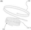
图1B是本申请一种定位装置的一实施例的示意图;1B is a schematic diagram of an embodiment of a positioning device of the present application;
图2A-2H是本申请一种定位装置的第一弯曲结构的多个实施例的示意图;2A-2H are schematic diagrams of multiple embodiments of a first bending structure of a positioning device of the present application;
图2I是将图2A所示的第一弯曲结构释放后在撤去第二弯曲结构后的实施例的剖视图;2I is a cross-sectional view of the embodiment after the first bending structure shown in FIG. 2A is released and the second bending structure is removed;
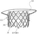
图2J是在图2I的基础上释放人工瓣膜的实施例的示意图;Figure 2J is a schematic diagram of an embodiment of releasing a prosthetic valve on the basis of Figure 2I;
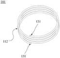
图3A是本申请一种定位装置的第一弯曲结构的实施例的示意图;3A is a schematic diagram of an embodiment of a first bending structure of a positioning device of the present application;
图3B是将图3A所示的第一弯曲结构在撤去第二弯曲结构后的实施例的剖视图;3B is a cross-sectional view of an embodiment of the first curved structure shown in FIG. 3A after removing the second curved structure;
图4A是本申请一种定位装置的第一弯曲结构的另一实施例的示意图;4A is a schematic diagram of another embodiment of a first bending structure of a positioning device of the present application;
图4B是将图4A所示的第一弯曲结构在撤去第二弯曲结构后的实施例的剖视图;4B is a cross-sectional view of an embodiment of the first curved structure shown in FIG. 4A after removing the second curved structure;
图5是本申请一种第二弯曲结构的第二线圈内侧形成多个切缝的实施例的示意图;5 is a schematic diagram of an embodiment of forming a plurality of slits on the inner side of a second coil of a second bending structure of the present application;
图6A是图5所示的第二弯曲结构的第二线圈未弯曲时的切缝的状态示意图;6A is a schematic view of the state of the slit when the second coil of the second bending structure shown in FIG. 5 is not bent;
图6B是图5所示的第二弯曲结构的第二线圈弯曲时的切缝的状态示意图;FIG. 6B is a schematic view of the state of the slit when the second coil of the second bending structure shown in FIG. 5 is bent;
图7A是本申请一种第三弯曲结构的一实施例在体内释放时的示意图;7A is a schematic diagram of an embodiment of a third bending structure of the present application when it is released in vivo;
图7B本申请一种第三弯曲结构的一实施例在心室部分释放后的示意图;7B is a schematic diagram of an embodiment of a third bending structure of the present application after the ventricle is partially released;
图7C本申请一种第二弯曲结构的一实施例撤离后的示意图。FIG. 7C is a schematic diagram of an embodiment of a second bending structure of the present application after being evacuated.
元件标号component number
10:定位装置;C2:原生瓣叶前后连合处;101:第一弯曲结构;102:第二弯曲结构;103:第三弯曲结构;112:第一线圈;112-1:近端的第一线圈;112-2:远端的第一线圈;113:第二线圈;W:第一间距;N:第二间距;122:弧形延伸部;123:切缝;123a:凸起;123b:凹槽;H:第二线圈径向方向的高度;131:保护件;141:被动锁定件;20:输送系统;201:第一输送装置;202:第二输送装置;30:人工瓣膜;301:支撑单元。10: positioning device; C2: anteroposterior commissure of native leaflets; 101: first curved structure; 102: second curved structure; 103: third curved structure; 112: first coil; a coil; 112-2: first coil at the distal end; 113: second coil; W: first pitch; N: second pitch; 122: arcuate extension; 123: slit; 123a: protrusion; 123b : groove; H: height of the second coil in the radial direction; 131: protector; 141: passive locking member; 20: delivery system; 201: first delivery device; 202: second delivery device; 30: artificial valve; 301: Support unit.
具体实施方式Detailed ways
为了使本领域的人员更好地理解本申请实施例中的技术方案,下面将结合本申请实施例中的附图,对本申请实施例中的技术方案进行清楚、完整地描述,显然,所描述的实施例仅是本申请实施例一部分实施例,而不是全部的实施例。基于本申请实施例中的实施例,本领域普通技术人员所获得的所有其他实施例,都应当属于本申请实施例保护的范围。In order to make those skilled in the art better understand the technical solutions in the embodiments of the present application, the following will clearly and completely describe the technical solutions in the embodiments of the present application with reference to the accompanying drawings in the embodiments of the present application. The embodiments described above are only a part of the embodiments of the present application, rather than all the embodiments. All other embodiments obtained by persons of ordinary skill in the art based on the embodiments in the embodiments of the present application should fall within the protection scope of the embodiments of the present application.
所述的“近端”是指当将心脏瓣膜定位装置植入心脏时,人工瓣膜组件靠近心房或心室的一端。所述的“远端”是指当将人工瓣膜组件植入心脏时,人工瓣膜组件远离心房或心室的一端。The "proximal end" refers to the end of the prosthetic valve assembly that is close to the atrium or ventricle when the heart valve positioning device is implanted in the heart. The "distal end" refers to the end of the prosthetic valve assembly remote from the atrium or ventricle when the prosthetic valve assembly is implanted into the heart.
“流入端”和“流出端”是对应于血液自心房经由心脏瓣膜流入心室的流动方向而言的。"Inflow" and "Outflow" correspond to the direction of flow of blood from the atrium through the heart valve into the ventricle.
本申请的人工瓣膜组件适用于至少部分替代人体心脏的原生二尖瓣或三尖瓣,本申请实施例将以二尖瓣为例进行说明。The artificial valve assembly of the present application is suitable for at least partially replacing the native mitral valve or tricuspid valve of the human heart, and the embodiment of the present application will take the mitral valve as an example for description.
如图1A所示,二尖瓣也被称为左房室瓣,是形成在左心室和左心房之间的屏障。正常情况下,二尖瓣的开合是由左心房和左心室间的压力差调节的,在心脏舒张期,左心房压力大于左心室,二尖瓣打开,反之,在心脏收缩期,左心室压力大于左心房,二尖瓣关闭。与主动脉瓣相比,二尖瓣整体结构呈D型,瓣环尺寸较大,钙化较少,假如植入人工瓣膜,原生二尖瓣不能为人工瓣膜提供足够的支撑力,使人工瓣膜固定在病变的二尖瓣处;且左室流出道与二尖瓣前瓣叶相邻,人工瓣膜的植入还可能会引起左室流出道梗阻(LVOTO)。As shown in Figure 1A, the mitral valve, also known as the left atrioventricular valve, is the barrier that forms between the left ventricle and the left atrium. Normally, the opening and closing of the mitral valve is regulated by the pressure difference between the left atrium and the left ventricle. During diastole, the pressure in the left atrium is greater than that in the left ventricle, and the mitral valve opens, whereas during systole, the left ventricle opens. The pressure is greater than the left atrium, and the mitral valve closes. Compared with the aortic valve, the overall structure of the mitral valve is D-shaped, the size of the valve annulus is larger, and the calcification is less. If a prosthetic valve is implanted, the native mitral valve cannot provide sufficient support for the prosthetic valve, so that the prosthetic valve can be fixed. Implantation of the prosthetic valve may also cause left ventricular outflow tract obstruction (LVOTO) at the diseased mitral valve; and the left ventricular outflow tract is adjacent to the anterior mitral valve leaflets.
下面结合本申请实施例附图进一步说明本申请实施例具体实现。The specific implementation of the embodiments of the present application is further described below with reference to the accompanying drawings of the embodiments of the present application.
参见图1B至图7C,在本申请一具体实现中,提供一种心脏瓣膜定位装置10,其与输送系统20连接,用于当处于输送状态时,借由输送系统20将定位装置10输送至心脏。输送系统20可以为包含鞘管的输送系统20,定位装置10置于鞘管中经由人体导管,例如血管输送至心脏瓣膜处进行释放,当处于释放状态时,将定位装置10释放于原生瓣叶之间。Referring to FIGS. 1B to 7C , in a specific implementation of the present application, a heart
定位装置10包括:第一弯曲结构101,其在释放状态下形成具有第一尺寸的螺旋形弯曲结构;第二弯曲结构102,其在释放状态下形成具有第二尺寸的螺旋形弯曲结构,第二尺寸>第一尺寸,第二弯曲结构102具有中空的第一腔体,以供第一弯曲结构101穿设于其中,形成第三弯曲结构103;第三弯曲结构103的远端为自由端,近端与输送系统20连接,第三弯曲结构103在释放状态下形成具有第三尺寸的螺旋形弯曲结构,其中,第一尺寸<第三尺寸≤第二尺寸;当处于输送状态时,第三弯曲结构103以延展状态置于输送系统20中,当处于释放状态时,第三弯曲结构103由远端至近端逐渐释放,并自原生瓣叶的的内表面经由原生瓣叶前后连合处进入外表面,从而以第三尺寸呈螺旋形地捕捉原生瓣叶,之后第二弯曲结构102与第一弯曲结构101脱离,且随输送系统20撤出,将第一弯曲结构以第一尺寸留置在原生瓣膜处。第一弯曲结构101可滑动地穿设于第二弯曲结构102中。第一弯曲结构101和第二弯曲结构102可以由记忆材料制成,以预先设置好各自在释放状态下的尺寸和形状。第二弯曲结构102的刚度可以大于或小于第一弯曲结构101的刚度,例如,当第二弯曲结构102预先设置为第二尺寸,即在释放状态下即为第二尺寸时,第二弯曲结构102的刚度可以大于第一弯曲结构101的刚度;当第二弯曲结构102不能预先设置为第二尺寸,即在释放状态下的尺寸未达到第二尺寸,需要借助外力达到第二尺寸时(如图5所示的实施例),第二弯曲结构102的刚度可以小于第一弯曲结构101的刚度。由此,第三弯曲结构的形状主要由第二弯曲结构102确定,在释放状态下,第二弯曲结构102的构型与第一弯曲结构101的构型可以相同或不同。The
定位装置10在释放时,第一弯曲结构101穿设于弯曲结构的第一腔体中形成第三弯曲结构103,以第三直径释放,定位装置10远离输送系统20的一端穿过瓣膜前后连合处C2,与原生瓣叶外表面(即面向心室壁的一面)相贴合,随着第三弯曲结构103的释放,第三弯曲结构103的远端环绕原生瓣叶外表面运动,将原生瓣叶圈入第三弯曲结构103内,由于伴随有反流的二尖瓣瓣环较大,心脏舒张期前瓣与后瓣之间的距离增大,若定位装置10的直径偏小(例如定位装置10只采用直径较小的第一弯曲结构101),在释放过程中定位装置10的远端经过瓣膜前后连合处时,很容易进入瓣叶内表面,导致原生瓣叶捕获失败,因此以较大的第三直径输送时,可以保证将原生瓣叶完全捕获。When the
定位装置10以较大的第三直径捕获原生瓣叶后将第二弯曲结构102撤出,第一弯曲结构101留在原生瓣叶处,以第一尺寸为心脏的原生瓣膜提供锚定支撑作用,第一弯曲结构101在心室的部分将原生瓣叶捕捉在第一弯曲结构101内部,在一定程度上限制原生瓣叶的活动,可以避免前瓣叶大幅度活动引起左室流出道梗阻,同时,原生瓣叶仍可以保持一定程度的开合,不会造成急性重度反流的发生,在人工瓣膜植入之前,还可以维持正常的瓣叶功能,对人体血液循环系统影响较小。The
本申请一实施例还提供与定位装置10配合使用的人工瓣膜30,其包括:人工瓣叶;以及筒状支撑单元301,人工瓣叶周向固定于支撑单元301的内侧,且支撑单元301与第一弯曲结构101相适配,以使当第二弯曲结构102与第一弯曲结构101脱离后,将人工瓣膜30置入第一弯曲结构101的内侧,以将原生瓣叶夹持在筒状支撑单元301与定位装置10之间。筒状支撑单元301可以为圆筒状、锥形筒状或其他非圆筒状。第一线圈的内侧尺寸与直径与筒状支撑单元301的外侧相匹配(例如第一线圈的内径与筒状支撑单元301的外径相匹配),人工瓣膜30通过与定位装置10的径向过盈配合及摩擦力锚定在原生瓣叶处,替代原生瓣叶的功能。另外,第二线圈113撤出后,此时第一线圈已恢复至第一尺寸(第一尺寸小于原生瓣环的直径),再将合适的人工瓣膜30输送释放至第一线圈的内部,实现定位装置10与人工瓣膜30的分步输送,从而可以减小输送系统20的尺寸(例如鞘管的尺寸),减轻血管并发症的风险。An embodiment of the present application also provides a
请参考图3A至图4B,在本申请一实施例中,第一弯曲结构101可以包括多个第一线圈,第二弯曲结构102包括多个第二线圈113。相邻的第一线圈或相邻的第二线圈113可分别相互连接形成螺旋形结构或其他形状的结构。第二弯曲结构102的构型与第一弯曲结构101的构型可以相同或不同。如图3A所示,在一可选实施例中,第一弯曲结构101的多个第一线圈的直径相同,与第一弯曲结构101搭配使用的第二弯曲结构102的多个第二线圈113的直径可以相同或不同。如图4A所示,在另一可选实施例中,第一弯曲结构101的多个第一线圈的自近端至远端的直径依次减小,即流入端直径大于流出端直径,形成类似于倒锥形的结构,与其匹配的第二弯曲结构102的多个第二线圈113的自近端至远端的直径可以依次减小或呈现为其他方式,例如所有第二线圈113等直径。可以与倒锥形筒状支撑单元301相匹配,在心房的压力作用下不易脱落至心室中。第一弯曲结构101的第一线圈可以由具有一定外径的实心丝材或中空管体组成。第一线圈横截面可以是椭圆形、矩形、圆形或其他任意合适的形状。需要说明的是,第二线圈113的直径不一定要与第一线圈112完全对应,因为即便第一线圈112的形状不同,由于第二线圈113的刚度大于第一线圈112的刚度,当将第一线圈112置于第二线圈113中组装为第三弯曲结构103时,第一线圈112仍然受第二线圈113的限制,使得第三弯曲结构103的形状接近于第二线圈113的形状。Referring to FIGS. 3A to 4B , in an embodiment of the present application, the
需要说明的是,本申请实施例中所述的“第二尺寸”、“第一尺寸”是指当第二弯曲结构102和第一弯曲结构101在各自独立释放后的尺寸,即第一弯曲结构101未穿设于第二弯曲结构102的第一腔体中时第二弯曲结构102和第一弯曲结构101各自释放后的尺寸。“第三尺寸”是指第一弯曲结构101穿设于第二弯曲结构102的第一腔体中形成的第三弯曲结构103释放后的尺寸。It should be noted that the "second size" and "first size" described in the embodiments of the present application refer to the size of the
此外,所述的“第一尺寸”、“第二尺寸”、“第三尺寸”分别是指第一弯曲结构101、第二弯曲结构102、第三弯曲结构103释放后在空间所形成的尺寸,而当将各尺寸进行比较时,例如第二尺寸>第一尺寸、第一尺寸<第三尺寸≤第二尺寸是指将欲进行比较的第一弯曲结构101、第二弯曲结构102、第三弯曲结构103的相对应的部位或线圈的直径进行比较,例如在一实施例中,第二尺寸>第一尺寸是指将第二弯曲结构102的自远端至近端的每个第二线圈113的直径分别与第一弯曲结构101的自远端至近端的每个第一线圈112的直径一一对应进行比较,且比较结果为大于。In addition, the "first size", "second size", and "third size" refer to the size formed in the space after the first
当所有的第二线圈113和第一线圈112均为等直径时,“第二尺寸”、“第一尺寸”和“第三尺寸”分别指第二线圈113的直径、第一线圈112的直径和第三弯曲结构103的线圈的直径。当第二线圈113和第一线圈112其中之一或全部为非等直径时,“第二尺寸”、“第一尺寸”和“第三尺寸”是指以相同标准分别在第二线圈113、第一线圈112和第三弯曲结构103的线圈的相对应的部位测量的各尺寸,例如当第二线圈113与第一线圈112的远端的线圈为弧形,而其他线圈均为等直径的圆(如图1所示),“第二尺寸”和“第一尺寸”分别既包括远端的线圈的尺寸,也包括其他线圈的尺寸,远端的线圈的尺寸可以为线圈的圆弧半径,其他线圈的尺寸可以为线圈的直径。When all the
由于第二弯曲结构102的刚度大于第一弯曲结构101的刚度,第一弯曲结构101的形状可以与第二弯曲结构102相同或不相同,第二弯曲结构102与第一弯曲结构101组装为第三弯曲结构103后,第一弯曲结构101会趋向于形成接近第二弯曲结构102的形状。例如当第一弯曲结构101包括多个等直径的第一线圈112时,第二弯曲结构102可以包括多个直径不同的第二线圈113;当第一弯曲结构101包括多个直径递减的第一线圈112而形成锥形时,第二弯曲结构102可以包括多个等直径的第二线圈113。Since the rigidity of the
如图1所示,在本申请一实施例中,远端的第一线圈112-2的直径大于非远端的其他第一线圈112的直径,相应地,位于远端的第二线圈113的直径大于非远端的其他第二线圈113的直径,以利于对原生瓣叶的捕捉。位于远端的第一线圈112或第二线圈113的材质的刚度可以大于其他第一线圈112或第二线圈113的材质的刚度,或者在材质相同的情况下制作第一弯曲结构101或第二弯曲结构102,将位于远端的第一线圈112或第二线圈113的直径加工成大于其他第一线圈112或第二线圈113的直径,或者将位于远端的第一线圈112或第二线圈113单独加工,之后通过铆接、焊接等方式与其他第一线圈112或第二线圈113组装在一起。As shown in FIG. 1 , in an embodiment of the present application, the diameter of the first coil 112 - 2 at the distal end is larger than the diameter of the other
在本申请一实施例中,第一弯曲结构101的相邻第一线圈112之间具有第一间距W,且第一间距W为相邻第一线圈112之间的最大间距,最大间距是指当第一弯曲结构101的的多对相邻第一线圈112的间距不同时,取其中最大的间距值,第二弯曲结构102的相邻第二线圈113之间具有第二间距N,且第二间距N为相邻第二线圈113之间的最小间距,最小间距是指当第二弯曲结构102的的多对相邻第二线圈113的间距不同时,取其中最小的间距值,其中第二间距N≥第一间距W。因此,在输送时,可以时第三弯曲结构103的相邻线圈之间的间距接近第二弯曲结构102的相邻线圈之间的间距,而当第二弯曲结构102脱离第一弯曲结构101后,第一弯曲结构101的相邻线圈之间的间距恢复至较小的间距,这样相邻线圈之间在捕获瓣叶夹持过程中不容易相互干涉。In an embodiment of the present application, there is a first distance W between adjacent
在本申请一实施例中,当第三弯曲结构103呈螺旋形地捕捉原生瓣叶之后,将第二弯曲结构102撤出,剩余第一弯曲结构101在原生瓣叶处,第一弯曲结构101的至少一部分第一线圈112分布于原生瓣叶的内表面,可以是半个线圈、三分之二个线圈、一个线圈或其他数量的线圈,如图2I、3B、4B所示,以从内表面和外表面均夹持住原生瓣叶,夹持更为牢固。In an embodiment of the present application, after the third
如图2A-2G所示,在本申请一实施例中,第一弯曲结构101设有弧形延伸部122,弧形延伸部122的一端与输送系统20可拆卸连接,另一端与位于第一弯曲结构101近端的第一线圈112-1固定连接,在释放状态下,弧形延伸部122的直径大于第一线圈112的直径,释放后,弧形延伸部122与近端的一个或多个第一线圈112均形成于原生瓣叶的内表面,位于心房部分的瓣环处,以增加第一弯曲结构101在原生瓣膜处的固定力。相应地,第二弯曲结构102也做成与第一弯曲结构101类似的结构,以供第一弯曲结构101穿过。如图2A-2D,弧形延伸部122可以为弧形、波浪形、葫芦状、倒刺状等,以增大摩擦力。再如图2E所示,弧形延伸部122可以为多个线圈连接成螺旋结构,这些线圈的直径可以大于第一线圈112。如图2F所示,弧形延伸部122包括多个线圈,线圈的两端均汇总连接在一起,其中,一端与输送系统20可拆卸连接,另一端与位于第一弯曲结构101近端的第一线圈112-1固定连接。如图2G所示,弧形延伸部122包括多个线圈,这些线圈的一端汇总连接到一起,另一端为自由状态,因此形成多个端,多个端均与输送系统20可拆卸连接。上述弧形延伸部122仅用于示例性说明,弧形延伸部122还可以采用其他的构型。As shown in FIGS. 2A-2G , in an embodiment of the present application, the first
如图5-6B所示,在本申请一实施例中,第二弯曲结构102的第二线圈113内侧形成多个切缝123,切缝123相对的两侧边缘分别形成形状相互匹配的凸起123a和凹槽123b,当第二弯曲结构102的第二线圈113弯曲时,凸起123a与凹槽123b相抵靠,形成第二尺寸。多个切缝123可以等距分布,使第二线圈113具有指定最小弯曲曲率以形成第二直径;第二线圈113上的多个切缝123还可以以不同的间距分布,以使多个第二线圈113具有不同的最小弯曲曲率以形成不同的直径。As shown in FIGS. 5-6B , in an embodiment of the present application, a plurality of
可选地,切缝123沿第二弯曲结构102的第二线圈径向方向平面展开的高度H小于或等于第二弯曲结构102的线圈的外径周长的60%。Optionally, the height H of the
如图2A所示,在本申请一实施例中,第一弯曲结构101的远端设有保护件131,保护件131具有光滑的表面,其形状可以为圆形凸起或其他适合的形状,第二弯曲结构102的远端可以稍短于第一弯曲结构101的远端,以露出保护件131,用于避免植入第一弯曲结构101和第二弯曲结构102时,对原生瓣叶或其他人体组织造成划伤。As shown in FIG. 2A , in an embodiment of the present application, the distal end of the first
如图2A所示,在本申请一实施例中,第一弯曲结构101和第二弯曲结构102的其中至少一者的近端设有被动锁定件141,用于与输送系统20锁定连接。被动锁定件141可以是通孔、盲孔、凹槽等,被动锁定件141可以为第一弯曲结构101或第二弯曲结构102的一部分,或者通过焊接、铆接、粘接与第一弯曲结构101的近端端部连接。相应地,输送系统20设有主动锁定件,以与被动锁定件141锁紧或解离。As shown in FIG. 2A , in an embodiment of the present application, the proximal end of at least one of the first
如图2H所示,在本申请一实施例中,第一弯曲结构101的外表面可以覆有生物相容性良好的高分子覆膜,可以促进内皮化。As shown in FIG. 2H , in an embodiment of the present application, the outer surface of the first
输送系统20可以包括具有输送鞘管的第一输送装置201和第二输送装置202,第二输送装置202的输送鞘管的直径小于第一输送装置201的输送鞘管的直径,以使第二输送装置202的输送鞘管置于第一输送装置201的输送鞘管中。The delivery system 20 may include a first delivery device 201 and a second delivery device 202 having a delivery sheath, the delivery sheath of the second delivery device 202 having a diameter smaller than the diameter of the delivery sheath of the first delivery device 201, such that the second delivery device 202 has a diameter smaller than that of the delivery sheath. The delivery sheath of the delivery device 202 is placed in the delivery sheath of the first delivery device 201 .
如图7A-7C所示,本申请一实施例还提供一种心脏瓣膜定位方法,该方法包括:将上述的心脏瓣膜定位装置10的第三弯曲结构103以延展状态置于输送系统20中,先将第一输送装置201穿过房间隔,之后通过第一输送装置201建立的通路,将第二输送装置202的远端输送至原生瓣叶前后连合处C2,定位装置10通过第二输送装置202输送至原生瓣叶前后连合处C2,定位装置10释放时,第三弯曲结构103由远端至近端逐渐释放,并先穿过原生瓣叶前后连合处C2,自原生瓣叶的内表面经由原生瓣叶前后连合处进入外表面,随着第三弯曲结构103以第三直径释放,第三弯曲结构103的线圈自远端至近端呈螺旋形地捕捉原生瓣叶,将其捕捉进第三弯曲结构103所形成的线圈内。当第三弯曲结构103完全释放后,将第二弯曲结构102自远端向近端撤离至连合处C2,第一弯曲结构101也随之逐渐释放,其直径恢复至第一尺寸,同时第一弯曲结构101的相邻第一线圈112之间的间距缩小。随后将第二弯曲结构102和和第二输送装置202一起撤回至第一输送装置201中,第一弯曲结构101位于近端的第一线圈112和弧形延伸部122释放,之后将第一弯曲结构101的被动锁定件141与第一输送装置201或第二输送装置202上的主动锁定件解离,完成第一弯曲结构101的释放。As shown in FIGS. 7A-7C, an embodiment of the present application further provides a method for positioning a heart valve, the method comprising: placing the third
如图7C所示,当第二弯曲结构102完全撤离后,第一弯曲结构101剩余在体内,第一弯曲结构101的心房部分和心室部分的连接处具有显影性,显影性可以通过自身材料性能或者增加显影结构(例如显影环、显影丝、显影片等)来实现,在释放时使连接处位于原生瓣叶前后连合处C2附近,心房部分由连接处向左心房延伸,心室部分由连接处沿原生瓣叶内表面延伸出半圈,与位于原生瓣叶外表面的相邻线圈一起将瓣叶夹持在两者之间,防止第一弯曲结构101在瓣叶上滑脱。从图2F可以看出,位于瓣叶外表面的第一线圈112将前后瓣叶圈入第一弯曲结构101内部,使瓣叶可以自由开合的同时防止前瓣叶阻挡左室流出道,流入端的第一线圈112位于瓣膜内表面,其余的第一线圈112位于瓣叶外表面。As shown in FIG. 7C , when the second
本申请另一实施例还提供一种心脏瓣膜置换方法,该方法包括在将,之后植入人工瓣膜30,并将人工瓣膜30植入第一弯曲结构101的内侧。Another embodiment of the present application also provides a heart valve replacement method, which includes implanting the
最后应说明的是:以上实施例仅用以说明本申请实施例的技术方案,而非对其限制;尽管参照前述实施例对本申请进行了详细的说明,本领域的普通技术人员应当理解:其依然可以对前述各实施例所记载的技术方案进行修改,或者对其中部分技术特征进行等同替换;而这些修改或者替换,并不使相应技术方案的本质脱离本申请各实施例技术方案的精神和范围。Finally, it should be noted that the above embodiments are only used to illustrate the technical solutions of the embodiments of the present application, but not to limit them; although the present application has been described in detail with reference to the foregoing embodiments, those of ordinary skill in the art should understand that: It is still possible to modify the technical solutions recorded in the foregoing embodiments, or perform equivalent replacements to some of the technical features; and these modifications or replacements do not make the essence of the corresponding technical solutions deviate from the spirit of the technical solutions in the embodiments of the present application. scope.
Claims (19)
Priority Applications (1)
| Application Number | Priority Date | Filing Date | Title |
|---|---|---|---|
| CN202210642095.1ACN114948345A (en) | 2022-06-08 | 2022-06-08 | Heart valve positioning device, heart valve replacement component and implantation method |
Applications Claiming Priority (1)
| Application Number | Priority Date | Filing Date | Title |
|---|---|---|---|
| CN202210642095.1ACN114948345A (en) | 2022-06-08 | 2022-06-08 | Heart valve positioning device, heart valve replacement component and implantation method |
Publications (1)
| Publication Number | Publication Date |
|---|---|
| CN114948345Atrue CN114948345A (en) | 2022-08-30 |
Family
ID=82962325
Family Applications (1)
| Application Number | Title | Priority Date | Filing Date |
|---|---|---|---|
| CN202210642095.1APendingCN114948345A (en) | 2022-06-08 | 2022-06-08 | Heart valve positioning device, heart valve replacement component and implantation method |
Country Status (1)
| Country | Link |
|---|---|
| CN (1) | CN114948345A (en) |
Cited By (3)
| Publication number | Priority date | Publication date | Assignee | Title |
|---|---|---|---|---|
| CN115737207A (en)* | 2022-09-06 | 2023-03-07 | 上海汇禾医疗科技有限公司 | Heart valve positioning device, artificial valve system and implantation method thereof |
| CN115844592A (en)* | 2022-11-29 | 2023-03-28 | 上海汇禾医疗科技有限公司 | Heart valve positioning device, artificial heart valve system, implantation system and method |
| CN115969576A (en)* | 2022-11-18 | 2023-04-18 | 上海汇禾医疗科技有限公司 | Heart valve positioning device, artificial heart valve system, implantation system and method |
Citations (11)
| Publication number | Priority date | Publication date | Assignee | Title |
|---|---|---|---|---|
| CN102131479A (en)* | 2007-12-21 | 2011-07-20 | 梅德坦提亚国际有限公司 | Heart valve downsizing device and method |
| CN103987341A (en)* | 2011-01-04 | 2014-08-13 | 克利夫兰临床基金会 | Apparatus and method for treating a regurgitant heart valve |
| US20150094803A1 (en)* | 2013-09-30 | 2015-04-02 | The Cleveland Clinic Foundation | Apparatus and method for treating a regurgitant heart valve |
| US20160228247A1 (en)* | 2015-02-11 | 2016-08-11 | Edwards Lifesciences Corporation | Heart valve docking devices and implanting methods |
| CN106572905A (en)* | 2014-02-20 | 2017-04-19 | 米特拉尔维尔福科技有限责任公司 | Convoluted anchor for supporting a prosthetic heart valve, prosthetic heart valve and deployment device |
| CN109803610A (en)* | 2016-08-26 | 2019-05-24 | 爱德华兹生命科学公司 | Heart valve docking system |
| CN111110403A (en)* | 2020-01-14 | 2020-05-08 | 启晨(上海)医疗器械有限公司 | Heart valve device with anchoring ring and using method thereof |
| CN113303947A (en)* | 2021-06-17 | 2021-08-27 | 上海臻亿医疗科技有限公司 | Anchoring device for heart valve |
| CN113616381A (en)* | 2013-08-12 | 2021-11-09 | 米特拉尔维尔福科技有限责任公司 | Apparatus and method for implanting a replacement heart valve |
| CN113952081A (en)* | 2014-09-12 | 2022-01-21 | 米特拉尔维尔福科技有限责任公司 | Mitral valve repair and replacement devices and methods |
| CN114209471A (en)* | 2013-08-14 | 2022-03-22 | 米特拉尔维尔福科技有限责任公司 | Heart valve replacement devices and methods |
- 2022
- 2022-06-08CNCN202210642095.1Apatent/CN114948345A/enactivePending
Patent Citations (11)
| Publication number | Priority date | Publication date | Assignee | Title |
|---|---|---|---|---|
| CN102131479A (en)* | 2007-12-21 | 2011-07-20 | 梅德坦提亚国际有限公司 | Heart valve downsizing device and method |
| CN103987341A (en)* | 2011-01-04 | 2014-08-13 | 克利夫兰临床基金会 | Apparatus and method for treating a regurgitant heart valve |
| CN113616381A (en)* | 2013-08-12 | 2021-11-09 | 米特拉尔维尔福科技有限责任公司 | Apparatus and method for implanting a replacement heart valve |
| CN114209471A (en)* | 2013-08-14 | 2022-03-22 | 米特拉尔维尔福科技有限责任公司 | Heart valve replacement devices and methods |
| US20150094803A1 (en)* | 2013-09-30 | 2015-04-02 | The Cleveland Clinic Foundation | Apparatus and method for treating a regurgitant heart valve |
| CN106572905A (en)* | 2014-02-20 | 2017-04-19 | 米特拉尔维尔福科技有限责任公司 | Convoluted anchor for supporting a prosthetic heart valve, prosthetic heart valve and deployment device |
| CN113952081A (en)* | 2014-09-12 | 2022-01-21 | 米特拉尔维尔福科技有限责任公司 | Mitral valve repair and replacement devices and methods |
| US20160228247A1 (en)* | 2015-02-11 | 2016-08-11 | Edwards Lifesciences Corporation | Heart valve docking devices and implanting methods |
| CN109803610A (en)* | 2016-08-26 | 2019-05-24 | 爱德华兹生命科学公司 | Heart valve docking system |
| CN111110403A (en)* | 2020-01-14 | 2020-05-08 | 启晨(上海)医疗器械有限公司 | Heart valve device with anchoring ring and using method thereof |
| CN113303947A (en)* | 2021-06-17 | 2021-08-27 | 上海臻亿医疗科技有限公司 | Anchoring device for heart valve |
Cited By (5)
| Publication number | Priority date | Publication date | Assignee | Title |
|---|---|---|---|---|
| CN115737207A (en)* | 2022-09-06 | 2023-03-07 | 上海汇禾医疗科技有限公司 | Heart valve positioning device, artificial valve system and implantation method thereof |
| CN115969576A (en)* | 2022-11-18 | 2023-04-18 | 上海汇禾医疗科技有限公司 | Heart valve positioning device, artificial heart valve system, implantation system and method |
| CN115969576B (en)* | 2022-11-18 | 2025-09-16 | 上海汇禾医疗科技有限公司 | Heart valve positioning device, artificial heart valve system, implantation system and method |
| CN115844592A (en)* | 2022-11-29 | 2023-03-28 | 上海汇禾医疗科技有限公司 | Heart valve positioning device, artificial heart valve system, implantation system and method |
| CN115844592B (en)* | 2022-11-29 | 2025-09-16 | 上海汇禾医疗科技有限公司 | Heart valve positioning device, artificial heart valve system, implantation system and method |
Similar Documents
| Publication | Publication Date | Title |
|---|---|---|
| US11523901B2 (en) | Systems for placing a coapting member between valvular leaflets | |
| JP6517906B2 (en) | Stent, valved stent and method and delivery system thereof | |
| CN109310500B (en) | Heart valve repair device and method of implanting the same | |
| CN109789019B (en) | Heart Valve Docking Coils and Systems | |
| CN107613908B (en) | Systems and methods for heart valve therapy | |
| AU2015221440B2 (en) | A replacement valve | |
| CN108261257B (en) | Valve prosthesis and delivery method | |
| US10022222B2 (en) | Systems and methods for treating lumenal valves | |
| US9636223B2 (en) | Systems and methods for placing a coapting member between valvular leaflets | |
| CN114948345A (en) | Heart valve positioning device, heart valve replacement component and implantation method | |
| CN110678149A (en) | docking element | |
| EP4082484A1 (en) | Valve prosthesis | |
| BR102016030239B1 (en) | PROSTHETIC MITRAL VALVE COAPTING INTENSIFICATION DEVICE | |
| CN107920862B (en) | Systems and methods for heart valve therapy | |
| US20070100439A1 (en) | Chordae tendinae restraining ring | |
| WO2019128583A1 (en) | Cardiac valve prosthesis and stent thereof | |
| CN103997990A (en) | Prosthetic heart valve device and related systems and methods | |
| CN117159228B (en) | A valve prosthesis device with segmented conical structure | |
| CN117100458A (en) | Valve prosthesis device with selectively distributed barbs | |
| CN114848233A (en) | Prosthetic valve assembly, implantation system and implantation method | |
| CN115969576B (en) | Heart valve positioning device, artificial heart valve system, implantation system and method | |
| CN115844592A (en) | Heart valve positioning device, artificial heart valve system, implantation system and method | |
| CN115300184A (en) | Heart valve positioning device, artificial heart valve system, implantation system and method | |
| CN114515213A (en) | Prosthetic valve and prosthetic valve system | |
| CN114515212A (en) | Prosthetic Valves and Prosthetic Valve Systems |
Legal Events
| Date | Code | Title | Description |
|---|---|---|---|
| PB01 | Publication | ||
| PB01 | Publication | ||
| SE01 | Entry into force of request for substantive examination | ||
| SE01 | Entry into force of request for substantive examination |