CN114947210A - Smoking set with accelerated heat conduction and use method - Google Patents
Smoking set with accelerated heat conduction and use methodDownload PDFInfo
- Publication number
- CN114947210A CN114947210ACN202210709893.1ACN202210709893ACN114947210ACN 114947210 ACN114947210 ACN 114947210ACN 202210709893 ACN202210709893 ACN 202210709893ACN 114947210 ACN114947210 ACN 114947210A
- Authority
- CN
- China
- Prior art keywords
- battery
- circuit
- heat conduction
- heating element
- hollow cavity
- Prior art date
- Legal status (The legal status is an assumption and is not a legal conclusion. Google has not performed a legal analysis and makes no representation as to the accuracy of the status listed.)
- Pending
Links
Images


Classifications
- A—HUMAN NECESSITIES
- A24—TOBACCO; CIGARS; CIGARETTES; SIMULATED SMOKING DEVICES; SMOKERS' REQUISITES
- A24F—SMOKERS' REQUISITES; MATCH BOXES; SIMULATED SMOKING DEVICES
- A24F40/00—Electrically operated smoking devices; Component parts thereof; Manufacture thereof; Maintenance or testing thereof; Charging means specially adapted therefor
- A24F40/40—Constructional details, e.g. connection of cartridges and battery parts
- A—HUMAN NECESSITIES
- A24—TOBACCO; CIGARS; CIGARETTES; SIMULATED SMOKING DEVICES; SMOKERS' REQUISITES
- A24F—SMOKERS' REQUISITES; MATCH BOXES; SIMULATED SMOKING DEVICES
- A24F40/00—Electrically operated smoking devices; Component parts thereof; Manufacture thereof; Maintenance or testing thereof; Charging means specially adapted therefor
- A24F40/20—Devices using solid inhalable precursors
- A—HUMAN NECESSITIES
- A24—TOBACCO; CIGARS; CIGARETTES; SIMULATED SMOKING DEVICES; SMOKERS' REQUISITES
- A24F—SMOKERS' REQUISITES; MATCH BOXES; SIMULATED SMOKING DEVICES
- A24F40/00—Electrically operated smoking devices; Component parts thereof; Manufacture thereof; Maintenance or testing thereof; Charging means specially adapted therefor
- A24F40/40—Constructional details, e.g. connection of cartridges and battery parts
- A24F40/46—Shape or structure of electric heating means
- A—HUMAN NECESSITIES
- A24—TOBACCO; CIGARS; CIGARETTES; SIMULATED SMOKING DEVICES; SMOKERS' REQUISITES
- A24F—SMOKERS' REQUISITES; MATCH BOXES; SIMULATED SMOKING DEVICES
- A24F40/00—Electrically operated smoking devices; Component parts thereof; Manufacture thereof; Maintenance or testing thereof; Charging means specially adapted therefor
- A24F40/50—Control or monitoring
Landscapes
- Battery Mounting, Suspending (AREA)
Abstract
Description
Translated fromChinese技术领域technical field
本发明属于烟具领域,具体而言,涉及一种加速热传导烟具及使用方法。The invention belongs to the field of smoking articles, and in particular relates to an accelerated heat conduction smoking article and a using method.
背景技术Background technique
相关研究表明,传统卷烟燃烧温度在800℃以上,卷烟在燃烧的过程中会产生5000余种化学物质,其中致癌的化学物质就有80多种,其产生的烟雾对非吸烟人群的危害相当大。加热不燃烧技术是一种通过烟具直接加热烟草但不燃烧产生烟雾的技术,这种加热方式所产生的有害物质比通过燃烧传统卷烟所产生的有害物质大大减少,在满足消费者需求的同时又可以减少对身体的危害。Relevant studies have shown that the burning temperature of traditional cigarettes is above 800 ℃, and more than 5,000 kinds of chemical substances will be produced during the burning process of cigarettes, among which there are more than 80 kinds of carcinogenic substances. . Heat-not-burn technology is a technology that directly heats tobacco without burning it to generate smoke. The harmful substances produced by this heating method are greatly reduced than those produced by burning traditional cigarettes. It can reduce the harm to the body.
加热不燃烧技术的主要用具为加热不燃烧烟具,加热不燃烧烟具通过对烟草物料进行加热,从而发生热解反应,使烟草物料刚好加热到足以散发出烟草味道及烟雾的程度,以供用户吸食。The main appliance of the HNB technology is the HNB device. The HNB device heats the tobacco material to cause a pyrolysis reaction, so that the tobacco material is heated just enough to emit tobacco flavor and smoke for the user to smoke. .
现有的加热不燃烧烟具,不论是棒状结构还是盒状结构,其内一般具有用于盛装烟草制品的烟腔、用于加热烟草制品以形成烟雾的加热元件、用于向加热元件提供电力的电池、用于连接电池与电源的电路和承载该电路的线路板、用于控制电池向加热元件提供电力供给的控制电路和承载该电路的线路板等。Existing heat-not-burn smoking articles, whether in rod-like structures or box-like structures, generally have a smoking cavity for containing tobacco products, a heating element for heating tobacco products to form smoke, and a heating element for supplying electricity to the heating element. A battery, a circuit for connecting the battery to a power source and a circuit board carrying the circuit, a control circuit for controlling the battery to provide power supply to the heating element, and a circuit board carrying the circuit, etc.
棒状结构的加热不燃烧烟具相较于盒状结构而言,因具有尺寸小、方便握持且更符合传统卷烟的手持感而受到越来越多消费者的青睐。然而,棒状结构相较于盒状结构而言,其还存在体内安装空间有限的缺陷,较小的安装空间内要集成上述电池、加热元件、烟腔等结构,一方面会对棒状结构的轴向尺寸和径向尺寸产生较大程度的影响,另一方面会对其内线路板的连接、定位以及各组件装配之后向棒状外壳内的组装产生影响。Compared with the box-shaped structure, the heat-not-burn smoking device of the rod-shaped structure is favored by more and more consumers because it has a small size, is convenient to hold, and is more in line with the hand-held feeling of traditional cigarettes. However, compared with the box-shaped structure, the rod-shaped structure also has the disadvantage of limited installation space in the body. The above-mentioned structures such as batteries, heating elements, and smoke chambers must be integrated in a small installation space. On the one hand, the shaft of the rod-shaped structure will be affected. On the other hand, it will affect the connection and positioning of the circuit boards in it and the assembly of the components into the rod-shaped housing after assembly.
例如,受其它组件与空间的影响,现有加热不燃烧烟具的线路板与线路板之间的连接大多采用导线焊接在两端的电路板上,以实现电连接。对于该种连接方式而言:一方面会增加电池、导线、线路板组装后的径向尺寸,若烟具的外部尺寸一定,为满足三者组装后能够装入烟具,则需减小电池的体积,电池体积的减小会降低电池的容量,从而大大降低烟具的续航能力,若烟具的外部尺寸不定,为保证电池的续航能力,在正常加热不燃烧烟具所需电池尺寸的条件下外加上述导线的尺寸,会增加烟具的外部尺寸,不仅增加了烟具的整体重量,而且因外围变粗,会降低消费者的手感;另一方面,由于导线柔软,其定位和焊接很难保证批量一致性。For example, due to the influence of other components and space, the connection between the circuit board and the circuit board of the existing heat-not-burn smoking device mostly adopts wires to be welded on the circuit boards at both ends to realize electrical connection. For this connection method: on the one hand, the radial dimension of the assembled battery, wire and circuit board will be increased. If the external dimensions of the smoking device are constant, the volume of the battery needs to be reduced in order to meet the requirement that the three can be installed in the smoking device after assembly. , the reduction of the battery volume will reduce the capacity of the battery, thus greatly reducing the endurance of the smoking device. If the external size of the smoking device is uncertain, in order to ensure the battery's endurance, the above-mentioned wires should be added under the condition of the battery size required for the normal heating and non-burning smoking device. It will increase the external size of the smoking set, which not only increases the overall weight of the smoking set, but also reduces the consumer's hand feel due to the thicker periphery. On the other hand, due to the softness of the wire, its positioning and welding are difficult to ensure batch consistency.
授权公告号为CN110384260B的发明专利公开了一种加热不燃烧烟具,包括具有中空腔体的外壳和电路组件,中空腔体内设置有电池,所还包括至少部分位于所述中空腔体内的加热组件,所述加热组件用于加热能够至少部分收容于所述烟具的低温不燃烧卷烟;该加热不燃烧烟具虽然能够实现对低温不燃烧烟的加热,但是由于其加热区域被限制在部分低温不燃烧卷烟内,无法对整体的低温不燃烧卷烟进行加热,同时,也因为缺少热传导,使得与加热组件接触的烟草所受的加热温度高,远离加热组件的烟草所受的加热温度低,整个低温不燃烧卷烟受热不均匀,影响吸食口感。The invention patent with the authorization announcement number CN110384260B discloses a heat-not-burn smoking device, which includes a shell with a hollow cavity and a circuit assembly, a battery is arranged in the hollow cavity, and also includes a heating component at least partially located in the hollow cavity, The heating assembly is used to heat the low-temperature non-combustible cigarettes that can be at least partially accommodated in the smoking device; although the heat-not-burn smoking device can heat the low-temperature non-combustible smoke, its heating area is limited to part of the low-temperature non-combustible cigarettes. It is impossible to heat the whole low-temperature non-burning cigarette. At the same time, due to the lack of heat conduction, the heating temperature of the tobacco in contact with the heating component is high, and the heating temperature of the tobacco far from the heating component is low, and the whole low temperature does not burn. Uneven heating of cigarettes affects the taste of smoking.
发明内容SUMMARY OF THE INVENTION
本发明提供一种加速热传导烟具及使用方法,能够有效解决低温不燃烧卷烟受热不均匀,影响吸食口感的问题。The invention provides an accelerated heat conduction smoking tool and a use method, which can effectively solve the problem of uneven heating of low-temperature non-burning cigarettes and affecting the taste of smoking.
本发明是这样实现的:The present invention is realized in this way:
本发明的第一方面提供一种加速热传导烟具,包括具有中空腔体的外壳、电池、控制电路以及加热组件,所述电池设置在中空腔体内,所述电池与所述控制电路导通,所述控制电路用于控制所述电池到所述加热组件的电力供给;所述加热组件至少部分位于所述中空腔体内,所述加热组件用于加热能够至少部分收容于所述烟具的低温不燃烧卷烟;所述加热组件包括加热元件,所述加热元件的一端与所述控制电路电连接;所述加热元件内设置有加速热传导机构。A first aspect of the present invention provides an accelerated heat conduction smoking article, comprising a shell with a hollow cavity, a battery, a control circuit and a heating assembly, the battery is arranged in the hollow cavity, the battery is in conduction with the control circuit, and thus The control circuit is used to control the power supply from the battery to the heating assembly; the heating assembly is at least partially located in the hollow cavity, and the heating assembly is used to heat a low-temperature non-combustion capable of being at least partially accommodated in the smoking article A cigarette; the heating assembly includes a heating element, and one end of the heating element is electrically connected to the control circuit; an accelerated heat conduction mechanism is arranged in the heating element.
所述加热元件为中空结构,所述加速热传导机构包括设置在所述盖体内的微风扇以及设置在加热元件表面的多个通孔,当所述盖体盖合在所述外壳收容于所述烟具的低温不燃烧卷烟的端部时,所述微风扇与所述控制电路电连接。The heating element is a hollow structure, and the accelerated heat conduction mechanism includes a micro fan arranged in the cover body and a plurality of through holes arranged on the surface of the heating element. When the low temperature of the smoking device does not burn the end of the cigarette, the micro-fan is electrically connected with the control circuit.
其中,所述盖体的截面为多层结构,包括第一接线极和第二接线极,所述第一接线极和第二接线极之间设置有绝缘层,所述微风扇的两个电源接入端分别连接在第一接线极和第二接线极上,对应的,壳体用于收容所述烟具的低温不燃烧卷烟的端部也设置有第一接线极和第二接线极匹配的接线电路,所述接线电路与所述控制电路电连接,当盖体盖合到壳体用于收容所述烟具的低温不燃烧卷烟的端部时,第一接线极和第二接线极与控制电路电连接,得到供电,微风扇实现旋转。Wherein, the cross section of the cover body is a multi-layer structure, including a first terminal pole and a second terminal pole, an insulating layer is arranged between the first terminal pole and the second terminal pole, and the two power supplies of the micro fan The access ends are respectively connected to the first terminal pole and the second terminal pole. Correspondingly, the end of the housing used for accommodating the low-temperature non-combustible cigarette of the smoking device is also provided with a matching first terminal pole and second terminal pole. A wiring circuit, the wiring circuit is electrically connected with the control circuit, when the cover body is closed to the end of the housing for accommodating the low-temperature non-burning cigarette of the smoking device, the first wiring pole and the second wiring pole are connected to the control circuit. The circuit is electrically connected to obtain power supply, and the micro-fan realizes rotation.
所述电路组件包括沿所述中空腔体延伸的柔性电路板,所述柔性电路板具有:用于连接电池的正极接头和负极接头、第一电路区域、第二电路区域以及用以连接所述第一电路区域和第二电路区域的连接区域;The circuit assembly includes a flexible circuit board extending along the hollow cavity, the flexible circuit board having: a positive terminal and a negative terminal for connecting to a battery, a first circuit area, a second circuit area, and a circuit for connecting the the connection area of the first circuit area and the second circuit area;
其中,所述第一电路区域和所述第二电路区域均相对于所述连接区域向所述中空腔体的中心偏转;所述连接区域具有不短于所述电池的长度,且所述连接区域的至少部分贴附在所述电池的外表面上;所述第一电路区域沿垂直于所述中空腔体轴向的弯折线进行折叠而形成至少一个第一折叠部;所述第二电路区域沿垂直于所述中空腔体轴向的弯折线进行折叠而形成至少一个第二折叠部;所述第一折叠部和所述第二折叠部的延伸方向均与所述中空腔体的轴向大致平行;所述中空腔体内设置有用于支撑所述第一折叠部的第一支撑件以及用于支撑所述第二折叠部的第二支撑件;所述中空腔体内设置有电路板定位构件,所述适配电路的一端连接有充电接口,所述电路板定位构件具有用于收容所述充电接口的第二腔室;所述中空腔体内还设置有电路板支撑构件,所述电路板支撑构件包括第一夹持件和第二夹持件,所述第一夹持件和第二夹持件相互配合并形成用于收容至少部分所述第一电路区域的第一腔室,所述第一电路区域的至少部分外缘被夹持在所述第一夹持件和所述第二夹持件之间。Wherein, both the first circuit area and the second circuit area are deflected toward the center of the hollow cavity relative to the connection area; the connection area has a length not shorter than the battery, and the connection area At least part of the area is attached to the outer surface of the battery; the first circuit area is folded along a bending line perpendicular to the axial direction of the hollow cavity to form at least one first folded portion; the second circuit The region is folded along a bending line perpendicular to the axial direction of the hollow cavity to form at least one second folded part; the extension directions of the first folded part and the second folded part are both aligned with the axis of the hollow cavity are approximately parallel to each other; a first support member for supporting the first folded portion and a second support member for supporting the second folded portion are arranged in the hollow cavity; a circuit board positioning member is arranged in the hollow cavity One end of the adapter circuit is connected with a charging interface, the circuit board positioning member has a second cavity for accommodating the charging interface; a circuit board support member is also arranged in the hollow cavity, and the circuit board the board support member includes a first clamp and a second clamp that cooperate with each other and form a first cavity for receiving at least a portion of the first circuit area, At least a portion of the outer edge of the first circuit region is clamped between the first clamp and the second clamp.
所述控制电路设置在所述第一电路区域内,所述第二电路区域设置有适配电路,所述电池与所述适配电路导通,所述电池通过所述适配电路与外接器件电连接。The control circuit is arranged in the first circuit area, an adapter circuit is arranged in the second circuit area, the battery is connected to the adapter circuit, and the battery is connected to an external device through the adapter circuit electrical connection.
进一步的,所述柔性电路板还具有:Further, the flexible circuit board also has:
第一弯折部,所述第一弯折部位于所述连接区域与所述第一电路区域的结合位置处,所述第一电路区域经由所述第一弯折部相对于所述连接区域向所述中空腔体的中心偏转;第二弯折部,所述第二弯折部位于所述第二电路区域与所述连接区域的结合位置处,所述第二电路区域经由所述第二弯折部相对于所述连接区域向所述中空腔体的中心偏转。a first bending part, the first bending part is located at the joint position of the connection area and the first circuit area, and the first circuit area is relative to the connection area through the first bending part deflection towards the center of the hollow cavity; a second bending part, the second bending part is located at the joint position of the second circuit area and the connection area, the second circuit area passes through the first The two bent portions are deflected toward the center of the hollow cavity relative to the connecting region.
所述电池大体呈圆柱形,所述电池包括分别从所述电池的两个圆柱端面引出的正极耳和负极耳,所述正极接头与所述正极耳焊接固定,所述负极接头与所述负极耳焊接固定。所述正极耳和所述负极耳分别向所述电池的两个圆柱端面的中心位置折叠。The battery is generally cylindrical, and the battery includes a positive electrode lug and a negative electrode lug respectively drawn from two cylindrical end faces of the battery, the positive electrode joint is welded and fixed to the positive electrode lug, and the negative electrode joint is connected to the negative electrode. The ears are welded and fixed. The positive electrode tab and the negative electrode tab are respectively folded toward the center of the two cylindrical end faces of the battery.
进一步的,所述加热组件还包括隔热套筒,所述隔热套筒与所述电路板支撑构件毗邻,所述低温不燃烧卷烟的至少部分能够收容于所述隔热套筒内部。Further, the heating assembly further includes an insulating sleeve, the insulating sleeve is adjacent to the circuit board support member, and at least part of the low temperature non-burning cigarette can be accommodated inside the insulating sleeve.
可选的,所述加热元件是电热陶瓷管。Optionally, the heating element is an electrothermal ceramic tube.
本发明的第二方面提供一种加速热传导烟具的使用方法,该方法采用上述的加速热传导烟具,能够将所述加热元件插入到低温不燃烧卷烟的尾部,所述加热元件内的加速热传导机构将所产生的的热量从低温不燃烧卷烟的尾部快速传导到低温不燃烧卷烟的头部,对低温不燃烧卷烟进行整体充分低温烘烤。The second aspect of the present invention provides a method for using an accelerated heat conduction smoking article, the method adopts the above accelerated heat conduction smoking article, and the heating element can be inserted into the tail of a low temperature non-burning cigarette, and the accelerated heat conduction mechanism in the heating element will The heat generated is rapidly conducted from the tail of the low-temperature non-combustion cigarette to the head of the low-temperature non-combustion cigarette, and the whole low-temperature non-combustion cigarette is fully roasted at a low temperature.
由于采用了上述技术方案,本发明所取得的有益效果为:通过设置加速热传导机构,在将加热元件插入到低温不燃烧卷烟内后,加热元件内的高温空气通过加热元件上的多个通孔向外扩散,盖体中的风扇可以通过向外壳外排风的方式,使得可体内形成气压,使得加热元件附近的高温空气快速对流到整个快速到达整个低温不燃烧烟的内部,使得整个低温不燃烧烟的受热均匀,提供更好的吸食感。Due to the adoption of the above technical solutions, the present invention has the following beneficial effects: by setting the accelerated heat conduction mechanism, after the heating element is inserted into the low temperature non-combustion cigarette, the high temperature air in the heating element passes through the plurality of through holes on the heating element Spreading out, the fan in the cover can form air pressure in the body by exhausting air to the outside of the casing, so that the high-temperature air near the heating element can quickly convect to the entire interior of the entire low-temperature non-combustible smoke, so that the entire low-temperature non-combustible smoke The burning smoke is heated evenly, providing a better smoking feeling.
附图说明Description of drawings
为了更清楚地说明本发明实施方式的技术方案,下面将对实施方式中所需要使用的附图作简单地介绍,应当理解,以下附图仅示出了本发明的某些实施例,因此不应被看作是对范围的限定,对于本领域普通技术人员来讲,在不付出创造性劳动的前提下,还可以根据这些附图获得其他相关的附图。In order to explain the technical solutions of the embodiments of the present invention more clearly, the following briefly introduces the accompanying drawings used in the embodiments. It should be understood that the following drawings only show some embodiments of the present invention, and therefore do not It should be regarded as a limitation of the scope, and for those of ordinary skill in the art, other related drawings can also be obtained according to these drawings without any creative effort.
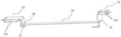
图1为本发明的一种实施方式的结构示意图。FIG. 1 is a schematic structural diagram of an embodiment of the present invention.
图2为本发明的一种实施方式的剖视图。FIG. 2 is a cross-sectional view of an embodiment of the present invention.
图3为本发明的一种实施中的盖体结构示意图。FIG. 3 is a schematic structural diagram of a cover body in an implementation of the present invention.
图4为本发明的一种实施例的盖体的截面示意图。4 is a schematic cross-sectional view of a cover body according to an embodiment of the present invention.
图5为本发明中所述电路板定位构件、柔性电路板、电池、电路板支撑构件及隔热座组装后的结构示意图。FIG. 5 is a schematic structural diagram of the circuit board positioning member, the flexible circuit board, the battery, the circuit board support member and the heat insulation seat after assembly according to the present invention.
图6为本发明中所述充电接口、柔性电路板、电池及加热元件组装后的结构示意图。FIG. 6 is a schematic structural diagram of the charging interface, the flexible circuit board, the battery and the heating element after assembly according to the present invention.
图7为本发明中所述柔性电路板的使用状态示意图。FIG. 7 is a schematic diagram of the use state of the flexible circuit board according to the present invention.
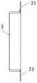
图8为本发明中所述电池的结构示意图。FIG. 8 is a schematic structural diagram of the battery in the present invention.
图9为本发明中所述电路板定位构件、柔性电路板、电路板支撑构件组装后的剖视图。FIG. 9 is a cross-sectional view of the circuit board positioning member, the flexible circuit board, and the circuit board support member after assembly according to the present invention.
其中,in,
1.外壳2.电池21.正极耳22.负极耳3.柔性电路板31.正极接头32.负极接头33.第一电路区域331.第一折叠部34.第二电路区域341.第二折叠部35.连接区域36.第一弯折部37.第二弯折部4.第一支撑件5.第二支撑件6.电路板支撑构件61.第一夹持件62.第二夹持件63.第一腔室64.弹性压片65.触发部7.电路板定位构件71.第二腔室8.加热组件81.加热元件82.隔热座83.隔热套筒84.微风扇85.通孔9.低温不燃烧卷烟10.按键11.充电接口12.盖体121.通风扇122.通风百叶1201.第一接线极1202.第二接线极1.
具体实施方式Detailed ways
为使本发明实施方式的目的、技术方案和优点更加清楚,下面将结合本发明实施方式中的附图,对本发明实施方式中的技术方案进行清楚、完整地描述,显然,所描述的实施方式是本发明一部分实施方式,而不是全部的实施方式。基于本发明中的实施方式,本领域普通技术人员在没有作出创造性劳动前提下所获得的所有其他实施方式,都属于本发明保护的范围。In order to make the purposes, technical solutions and advantages of the embodiments of the present invention clearer, the technical solutions in the embodiments of the present invention will be clearly and completely described below with reference to the accompanying drawings in the embodiments of the present invention. Obviously, the described embodiments These are some embodiments of the present invention, but not all of them. Based on the embodiments of the present invention, all other embodiments obtained by those of ordinary skill in the art without creative efforts shall fall within the protection scope of the present invention.
因此,以下对在附图中提供的本发明的实施方式的详细描述并非旨在限制要求保护的本发明的范围,而是仅仅表示本发明的选定实施方式。基于本发明中的实施方式,本领域普通技术人员在没有作出创造性劳动前提下所获得的所有其他实施方式,都属于本发明保护的范围。Accordingly, the following detailed description of the embodiments of the invention provided in the accompanying drawings is not intended to limit the scope of the invention as claimed, but is merely representative of selected embodiments of the invention. Based on the embodiments of the present invention, all other embodiments obtained by those of ordinary skill in the art without creative efforts shall fall within the protection scope of the present invention.
应注意到:相似的标号和字母在下面的附图中表示类似项,因此,一旦某一项在一个附图中被定义,则在随后的附图中不需要对其进行进一步定义和解释。It should be noted that like numerals and letters refer to like items in the following figures, so once an item is defined in one figure, it does not require further definition and explanation in subsequent figures.
在本发明的描述中,需要理解的是,术语“中心”、“纵向”、“横向”、“长度”、“宽度”、“厚度”、“上”、“下”、“前”、“后”、“左”、“右”、“竖直”、“水平”、“顶”、“底”、“内”、“外”、“顺时针”、“逆时针”等指示的方位或位置关系为基于附图所示的方位或位置关系,仅是为了便于描述本发明和简化描述,而不是指示或暗示所指的设备或元件必须具有特定的方位、以特定的方位构造和操作,因此不能理解为对本发明的限制。In the description of the present invention, it should be understood that the terms "center", "longitudinal", "lateral", "length", "width", "thickness", "upper", "lower", "front", " rear, left, right, vertical, horizontal, top, bottom, inside, outside, clockwise, counterclockwise, etc., or The positional relationship is based on the orientation or positional relationship shown in the drawings, which is only for the convenience of describing the present invention and simplifying the description, rather than indicating or implying that the referred device or element must have a specific orientation, be constructed and operated in a specific orientation, Therefore, it should not be construed as a limitation of the present invention.
此外,术语“第一”、“第二”仅用于描述目的,而不能理解为指示或暗示相对重要性或者隐含指明所指示的技术特征的数量。由此,限定有“第一”、“第二”的特征可以明示或者隐含地包括一个或者更多个该特征。在本发明的描述中,“多个”的含义是两个或两个以上,除非另有明确具体的限定。In addition, the terms "first" and "second" are only used for descriptive purposes, and should not be construed as indicating or implying relative importance or implying the number of indicated technical features. Thus, a feature defined as "first" or "second" may expressly or implicitly include one or more of that feature. In the description of the present invention, "plurality" means two or more, unless otherwise expressly and specifically defined.
实施例Example
如图1至图8所示,一种加速热传导烟具,其用于加热低温不燃烧卷烟。As shown in Figures 1 to 8, an accelerated heat conduction smoking device is used for heating low temperature non-burning cigarettes.
所述烟具包括具有中空腔体的外壳1,例如,图1示出了一种具有呈圆柱状且带有光滑表面的外壳1,但本发明中,所述外壳1的形状并不局限于图中示出的圆柱状结构,还可以是截面呈椭圆形的棒状结构、截面呈方形的棒状结构等,所述外壳1的表面也不一定是光滑表面,其还可以是能够增加质感的磨砂表面、具有能够增大摩擦力以防烟具从用户手中脱落的棱边的表面、为提升烟具外观的美观性能而增加各种花纹或纹理的表面等等。The smoking article includes a casing 1 with a hollow cavity. For example, FIG. 1 shows a casing 1 with a cylindrical shape and a smooth surface, but in the present invention, the shape of the casing 1 is not limited to that shown in the figure. The cylindrical structure shown in can also be a rod-shaped structure with an oval cross-section, a rod-shaped structure with a square cross-section, etc., the surface of the housing 1 is not necessarily a smooth surface, it can also be a matte surface that can increase texture , a surface with an edge that can increase the friction force to prevent the smoking device from falling off the user's hands, a surface with various patterns or textures to improve the appearance of the smoking device, and so on.
所述中空腔体内设置有电池2,如锂离子电池、聚合物电池等,所述电池2一方面与下述的加热元件81连接以实现对加热元件81的电能供应,另一方面,所述电池2通过充电接口11外接电源,可实现对电池2的充电。电池2的容量会影响每一支低温不燃烧卷烟的抽吸口数,电池2的体积是电池容量的其中一个影响因素,因此如何兼顾烟具的小体积和电池2的大续航成为本发明重点关注的技术问题。The hollow cavity is provided with a
本实施例中,所述烟具还包括电路组件,所述电路组件包括沿所述中空腔体延伸的柔性电路板3。所述柔性电路板3是指以聚酰亚胺或聚酯薄膜为基材制成的印刷电路板。In this embodiment, the smoking article further includes a circuit assembly, and the circuit assembly includes a
如图7所示,所述柔性电路板3具有用于连接电池2的正极接头31和负极接头32。作为优选,本实施例中,如图7所示,所述电池2包括分别从所述电池2的两个圆柱端面引出的正极耳21和负极耳22,所述正极接头31与所述正极耳21焊接固定,所述负极接头32与所述负极耳22焊接固定。相较于电池正负极与电路板接触通电的结构而言,本实施例通过电池正、负极耳与柔性电路板正、负极接头对应地焊接固定,实现电池2与柔性电路板3的一体化装配,有利于后续外壳1与内部电池2及电路组件的组装,提高组装效率。As shown in FIG. 7 , the
本实施例利用柔性电路板3代替现有技术中的导线,不仅可以减小柔性电路板3和电池2组装后的径向尺寸,而且不需要人工整理线路,提高了装配效率,此外,若采用导线,导线需要与两侧的电路板分别焊接固定,且导线需要与电池的正负极焊接固定,而本实施例只需要柔性电路板3与电池2正、负极耳焊接固定,大大减少了焊点数量,节省了焊接工序。In this embodiment, the
另外,如图6所示,本实施例中,所述正极接头31与正极耳21焊接固定后,所述负极接头32与负极耳22焊接固定后,所述正极耳21和所述负极耳22分别向所述电池2的两个圆柱端面的中心位置折叠,以使所述电池2与所述柔性电路板3组装后,所述正极耳21和所述负极耳22能够分别位于所述电池2的轴向投影范围内。In addition, as shown in FIG. 6 , in this embodiment, after the
上述正、负极耳与柔性电路板3焊接后的折叠方式:一方面,能够对焊点形成保护,保证了连接的可靠性和稳定性;另一方面,相较于焊接后,正、负极耳分别向电池2两个圆柱端面的外围折叠以使正、负极耳与电池2外围形成在同一直线上的结构而言,本实施例能够显著减小柔性电路板3和电池1组装后的轴向尺寸;再者,相较于焊接后,正、负极耳分别向电池两个圆柱端面的外围折叠以使正、负极耳位于电池的轴向投影范围外的结构而言,本实施例能够显著减小柔性电路板3和电池2组装后的径向尺寸。The above-mentioned folding method of the positive and negative electrodes after welding with the flexible circuit board 3: on the one hand, it can form protection for the solder joints and ensure the reliability and stability of the connection; on the other hand, compared with the positive and negative electrodes after welding, As far as the structure is folded to the periphery of the two cylindrical end faces of the
需要进一步说明的是,如图6所示,本实施例中,所述正极接头31和所述负极接头32位于下述连接区域35的轴线的同一侧,相较于正、负极接头分别位于连接区域35轴线的两侧的结构而言,本实施例能够减小柔性电路板3宽度方向的尺寸,有利于烟具的小型化。It should be further noted that, as shown in FIG. 6 , in this embodiment, the
本发明中,如图7所示,所述柔性电路板3还具有第一电路区域33、第二电路区域34以及用以连接所述第一电路区域33和第二电路区域34的连接区域35。In the present invention, as shown in FIG. 7 , the
所述连接区域35具有供电线和信号线,用以实现第一电路区域33、第二电路区域34及电池2的互连互通。在本发明中,所述连接区域35具有不短于所述电池2的长度,且所述连接区域35的至少部分贴附在所述电池2的外表面上,以减小柔性电路板3与电池2组装后的径向尺寸。作为优选,本实施例中所述连接区域35的宽度小于所述电池2的外径,从而使得所述连接区域35占据所述电池2径向投影的一小部分,相较于连接区域35占据所述电池2径向投影的一大部分并对电池2形成围包的结构而言,上述优选实施例一方面可以减少柔性电路板3与电池2组装后的径向尺寸,另一方面,有利于使用过程中柔性电路板3与电池2的散热。The
本实施例中,所述第一电路区域33设置有控制电路,所述第二电路区域34设置有适配电路,所述电池2分别与所述适配电路和控制电路导通。所述电池2通过所述适配电路与外接器件电连接,所述适配电路至少用于实现所述电池2的充电。所述适配电路的一端连接有充电接口11,所述外壳1上设置有与所述充电接口11位置相对的通孔,所述电池2通过所述充电接口11外接电源以进行电池2的充电。所述控制电路用于控制所述电池2到下述加热组件的电力供给。所述控制电路至少用于控制实现控制电池2与加热元件81的通断。In this embodiment, the
本发明中,所述第一电路区域33和所述第二电路区域34均相对于所述连接区域35向所述中空腔体的中心偏转,从而大大减小了所述柔性电路板3与所述电池2组装后的轴向尺寸。In the present invention, both the
具体而言,所述柔性电路板3还具有第一弯折部36,所述第一弯折部36位于所述连接区域35与所述第一电路区域33的结合位置处,所述第一电路区域33经由所述第一弯折部36相对于所述连接区域35向所述中空腔体的中心偏转。所述柔性电路板3还具有第二弯折部37,所述第二弯折部37位于所述第二电路区域34与所述连接区域35的结合位置处,所述第二电路区域34经由所述第二弯折部37相对于所述连接区域35向所述中空腔体的中心偏转。Specifically, the
进一步地,如图7所示,所述第一电路区域33沿垂直于所述中空腔体轴向的弯折线A-A进行折叠而形成至少一个第一折叠部331。所述第二电路区域34沿垂直于所述中空腔体轴向的弯折线进行折叠而形成至少一个第二折叠部341。如图2、图5和图6所示,该图示出了第一电路区域33具有两个第一折叠部331和第二电路区域34具有两个第二折叠部341的实施例,但本发明中,所述第一折叠部331和所述第二折叠部341的数量并不仅仅局限于图示中的两个。Further, as shown in FIG. 7 , the
更进一步地,如图2和图6所示,所述第一折叠部331和所述第二折叠部341的延伸方向均与所述中空腔体的轴向大致平行,从而减少了柔性电路板3整体的径向尺寸。当然,所述第一折叠部331和第二折叠部341的延伸方向也可与所述中空腔体的轴线形成一定的夹角α,例如,所述夹角α满足0°<α<90°。Further, as shown in FIGS. 2 and 6 , the extending directions of the first folded
如图2所示,所述充电接口11与所述第二折叠部341电连接,优选的,所述第一折叠部341和所述充电接口11被配置为两者组装并装配进入所述外壳1后,所述充电接口11位于所述中空腔体的中间位置。As shown in FIG. 2 , the charging
如图2所示,下述加热元件81与所述第一折叠部331电连接,优选的,所述第一折叠部331和所述加热元件81被配置为两者组装并装配进入所述外壳1后,所述加热元件81位于所述中空腔体的中间位置。As shown in FIG. 2 , the following
上述各种元器件的结构和布置方式能够带来将各元器件组装后轴向尺寸和径向尺寸得以缩减的有益效果,从而使烟具向着小型化的方向发展。从另一个角度来说,使用本实施例中各元器件的结构和布置方式,可以在同样尺寸的烟具中,使用较大体积的电池,从而增加电池的容量,提升电池的续航能力,提高用户体验。The structure and arrangement of the above-mentioned various components can bring about the beneficial effect of reducing the axial and radial dimensions of the components after assembling, so that the smoking apparatus develops in the direction of miniaturization. From another point of view, using the structure and arrangement of the components in this embodiment, a larger volume of battery can be used in a smoking appliance of the same size, thereby increasing the capacity of the battery, improving the battery life, and improving the user experience. experience.
所述中空腔体内设置有电路板定位构件7,所述电路板定位构件7具有至少用于收容部分所述充电接口11的第二腔室71。所述中空腔体内设置有用于支撑所述第二折叠部341的第二支撑件5,作为优选,所述第二支撑件5设置在所述第二腔室71内,所述第二支撑件5的设置避免了装配过程第二折叠部341的过度变形。A circuit
所述电路板定位构件7上设置有第二弹性锁止部,所述外壳1上设置有与所述第二弹性锁止部位置相对的第二锁止孔,至少部分所述第二弹性锁止部卡入所述第二锁止孔,以方便所述电路板定位构件7与所述外壳1的装配。The circuit
所述中空腔体内还设置有电路板支撑构件6,所述电路板支撑构件6与所述中空腔体的内壁相适配。本实施例中,所述“适配”至少下述两种情形中的一种情况:所述电路板支撑构件6的外部尺寸略小于所述中空腔体内径,以使所述电路板支撑构件6能够恰好收容于中空腔体内而不发生大幅的径向晃动,方便了组装过程;所述电路板支撑构件6上设置有与所述中空腔体内壁上对应位置的结构相配合的对应结构。A circuit board support member 6 is also provided in the hollow cavity, and the circuit board support member 6 is adapted to the inner wall of the hollow cavity. In this embodiment, the “fit” is at least one of the following two situations: the outer dimension of the circuit board support member 6 is slightly smaller than the inner diameter of the hollow cavity, so that the circuit board support member The circuit board support member 6 can be accommodated in the hollow cavity without significant radial shaking, which facilitates the assembly process; the circuit board support member 6 is provided with a corresponding structure matched with the structure at the corresponding position on the inner wall of the hollow cavity.
如图5所示,所述电路板支撑构件6沿电池2的轴向延伸,所述电池2的一端与所述电路板支撑构件6的一端相抵靠。所述电池2的另一端与所述电路板定位构件7的一端相抵靠,从而使得电路板定位构件7、柔性电路板3、电池2以及电路板支撑构件6组装后,电路板定位构件7与电路板支撑构件6能够对电池2形成夹持,并形成一个“一体化”的结构,方便后续上述组装后的元器件与外壳1的装配。As shown in FIG. 5 , the circuit board support member 6 extends along the axial direction of the
如图5和图9所示,所述第一电路区域33固定在所述电路板支撑构件6上。所述电路板支撑构件6包括第一夹持件61和第二夹持件62。作为优选,本实施例中所述第一夹持件61和所述第二夹持件62的断面均大体呈弧形,以使所述电路板支撑构件6大体呈圆柱状,一方面使所述电路板支撑构件6具有与所述中空腔体相适配的外形,方便装配,另一方面,圆柱状的结构相较于其它几何形状而言具有相对较大的内部空间,从而为所述第一电路区域33安装各种电子元件或者在下述第一腔室63内设置其它零部件提供了较大的安装空间。As shown in FIGS. 5 and 9 , the
本实施例中,所述第一夹持件61和所述第二夹持件62之间为可拆卸式连接。两者之间可拆卸式的连接方式有多种,例如可以通过卡接结构、磁吸结构或限位结构等实现两者之间的组装。作为优选,本实施例中,所述第一夹持件61和所述第二夹持件62通过卡接结构连接,所述卡接结构包括设置在所述第一夹持件61和所述第二夹持件62中的一个上的卡柱,以及设置在两者中的另一个上的卡槽。In this embodiment, the first clamping
所述第一电路区域33的至少部分外缘被夹持在所述第一夹持件61和第二夹持件62之间。所述电路板支撑构件6具有第一腔室63,所述第一、第二夹持件之间配合形成所述第一腔室63。至少部分所述第一电路区域33固定在所述第一腔室63内,从而使得装配过程中,所述电路板支撑构件6能够对所述第一电路区域33形成防护。作为优选,各所述第一折叠部331位于所述第一腔室63内。At least part of the outer edge of the
本实施例中,所述第一夹持件61的内侧壁设置有至少一个向所述第一腔室63内部延伸的第一夹持部(未图示);所述第二夹持件62的内侧壁设置有至少一个向所述第一腔室63内部延伸且与所述第一夹持部位置相对的第二夹持部(未图示)。其中一个所述第一折叠部331的部分外缘被夹持在所述第一夹持部和所述第二夹持部之间。作为优选,该第一折叠部的背面贴附有补强层,所述第一夹持部和第二夹持部夹持所述第一折叠部331具有补强层的区域。更进一步地,所述第一夹持件61或所述第二夹持件62设置有自内壁向第一腔室的内部延伸的支撑台,上述第一折叠部331的外缘放置在所述支撑台上,从而避免了因操作不当而造成第一夹持部和第二夹持部对第一折叠部夹持时,第一电路区域被夹持的部位和不被夹持的部位之间因受力不同而发生过度变形。In this embodiment, the inner side wall of the first clamping
如图9所示,当所述第一电路区域33具有多个第一折叠部331时,其余的第一折叠部相对于上述被夹持在所述第一夹持部和第二夹持部之间的第一折叠部沿垂直于中空腔体轴线的弯折线翻转并收容于所述第一腔室63内。作为优选,各所述第一折叠部331的背面均贴附有补强层。As shown in FIG. 9 , when the
所述第一电路区域33还设置有用于控制所述控制电路通断的电路开关。所述烟具还包括开关触发组件,通过触发所述开关触发组件以操作所述电路开关。所述开关触发组件包括设置在所述第一夹持件61和所述第二夹持件62中的其中一个上的弹性压片64,以及设置在所述外壳1上且与所述弹性压片64位置正对的按键10。所述弹性压片64面向所述第一电路区域33的一侧设置有触发部65,按下所述按键10,所述弹性压片64向所述第一电路区域33的方向运动,通过所述触发部65触发所述电路开关,以实现控制电路的导通或关闭。The
如图2和图9所示,所述中空腔体内设置有用于支撑所述第一折叠部331的第一支撑件4,作为优选,所述第一支撑件4设置在所述第一腔室63内。通过设置所述第一支撑件4,一方面方便所述柔性电路板3与所述电路板支撑构件6的安装,另一方面,能够增加所述第一电路区域33的承载性能,以使所述触发部65碰触所述电路开关时,电路开关能够及时作出响应。As shown in FIG. 2 and FIG. 9 , a first support member 4 for supporting the
所述第一夹持件61和所述第二夹持件62中的另一个设置有第一弹性锁止部,所述外壳1上设置有与所述第一弹性锁止部位置相对的第一锁止孔,至少部分所述第一弹性锁止部卡入所述第一锁止孔,以方便所述电路板支撑构件6与所述外壳1的装配。The other one of the first clamping
所述烟具还包括至少部分位于所述中空腔体内的加热组件,所述加热组件用于加热能够至少部分收容于所述烟具的低温不燃烧卷烟9,所述加热组件内设置有加速热传导机构。The smoking article further includes a heating assembly at least partially located in the hollow cavity, the heating assembly is used to heat the low temperature non-burning cigarette 9 that can be accommodated at least partially in the smoking article, and an accelerated heat conduction mechanism is arranged in the heating assembly.
所述加热组件包括加热元件81,所述加热元件81的一端与所述控制电路电连接。本发明中,所述加热元件81既可以是内部加热元件,又可以是外部加热元件,或者是内、外相互结合的加热元件。其中,“内部”和“外部”是以低温不燃烧卷烟9为基准进行定义的,具体而言,当加热元件以插入低温不燃烧卷烟的方式对低温不燃烧卷烟进行加热时,将其定义为内部加热元件,当加热元件以围包在低温不燃烧卷烟的外侧对低温不燃烧卷烟进行烘烤时,将其定义为外部加热元件,当加热元件既有围包在低温不燃烧卷烟外部的部分、又有插入低温不燃烧卷烟内部的部分时,将其定义为内、外相互结合的加热元件。The heating assembly includes a
所述内部加热元件可以采用任何的结构形式,例如,所述内部加热元件可以是延伸插入所述低温不燃烧卷烟的一根或多根加热针、加热杆、加热板或加热片,作为替代,所述内部加热元件还可以是加热金属丝或细丝等。如图2、图3和图5所示,其给出了加热针形式的内部加热元件。The inner heating element may take any structural form, for example, the inner heating element may be one or more heating needles, heating rods, heating plates or heating sheets extending into the low temperature non-burning cigarette, as an alternative, The internal heating element may also be a heating wire or filament or the like. As shown in Figures 2, 3 and 5, an internal heating element in the form of a heating needle is shown.
所述外部加热元件可以采用任何的结构形式,例如,所述外部加热元件采用在电介质衬底上的一个或多个加热箔片的形式。The external heating element may take any structural form, for example, the external heating element may take the form of one or more heating foils on a dielectric substrate.
如图2所示,加热元件81是中空结构,加速热传导机构包括设置在盖体12内的微风扇84以及设置在加热元件表面的多个通孔85,当盖体12盖合在所述外壳1的用于收容所述烟具的低温不燃烧卷烟9的端部时,所述微风扇84与所述控制电路电连接。As shown in FIG. 2 , the
其中,所述微风扇84与所述控制电路电连接的方式为:如图3-4所示,所述盖体12的截面为多层结构,包括第一接线极1201和第二接线极1202,所述第一接线极1201和第二接线极1202之间设置有绝缘层,所述微风扇84的两个电源接入端分别连接在第一接线极1201和第二接线极1202上,对应的,壳体用于收容所述烟具的低温不燃烧卷烟的端部也设置有第一接线极1201和第二接线极1202匹配的接线电路,所述接线电路与所述控制电路电连接,当盖体盖合到壳体用于收容所述烟具的低温不燃烧卷烟的端部时,第一接线极1201和第二接线极1202与控制电路电连接,得到供电,微风扇84实现旋转。The way in which the micro-fan 84 is electrically connected to the control circuit is as follows: as shown in FIGS. 3-4 , the cross-section of the
进一步的,所述盖体12的顶端还设置有散热百叶122。Further, the top of the
加热过程中,在微风扇84的作用下,加热元件81内的热空气通过多个通孔85吹入到加热元件81之外,并快速扩展到整个低温不燃烧卷烟内,使得低温不燃烧卷烟均匀受热。During the heating process, under the action of the micro fan 84, the hot air in the
如图2所示,所述加热组件还包括隔热套筒83,所述隔热套筒83与所述电路板支撑构件6毗邻,所述低温不燃烧卷烟9的至少部分能够收容于所述隔热套筒83内部,以实现加热低温不燃烧卷烟9的过程中,减少卷烟向外壳1部分的传热,避免烫手。As shown in FIG. 2 , the heating assembly further includes a
作为优选,如图2和图5所示,所述加热组件还包括隔热座82,所述隔热座82的一端安装于所述电路板支撑构件6,所述隔热套筒83抵靠在所述隔热座82的另一端,所述加热元件81的一端穿过所述隔热座82后与所述控制电路相连。Preferably, as shown in FIG. 2 and FIG. 5 , the heating assembly further includes a
本发明中,如图5所示,所述电路板定位构件7、柔性电路板3、电池2、加热元件81、电路板支撑构件6组装后作为一个整体装入所述外壳1,从而方便了所述烟具的装配,提高了自动化装配的程度和装配效率,同时自动化装配的过程还可避免因装连人员操作不当易引起柔性电路板3的损坏。In the present invention, as shown in FIG. 5 , the circuit
本发明的第二方面提供一种加速热传导烟具的使用方法,该方法采用上述的加速热传导烟具,能够将所述加速热传导烟具的加热元件插入到低温不燃烧卷烟的尾部,所述加热元件内的加速热传导机构将所产生的的热量从低温不燃烧卷烟的尾部快速传导到低温不燃烧卷烟的头部,对低温不燃烧卷烟进行全面低温烘烤。A second aspect of the present invention provides a method for using an accelerated heat conduction smoking article, the method adopts the above accelerated heat conduction smoking article, and the heating element of the accelerated heat conduction smoking article can be inserted into the tail of a low temperature non-burning cigarette, and the heating element in the heating element The accelerated heat transfer mechanism quickly conducts the generated heat from the tail of the low temperature non-burning cigarette to the head of the low temperature non-combusting cigarette, and performs comprehensive low-temperature baking on the low temperature non-combusting cigarette.
以上所述仅为本发明的优选实施方式而已,并不用于限制本发明,对于本领域的技术人员来说,本发明可以有各种更改和变化。凡在本发明的精神和原则之内,所作的任何修改、等同替换、改进等,均应包含在本发明的保护范围之内。The above descriptions are only preferred embodiments of the present invention, and are not intended to limit the present invention. For those skilled in the art, the present invention may have various modifications and changes. Any modification, equivalent replacement, improvement, etc. made within the spirit and principle of the present invention shall be included within the protection scope of the present invention.
Claims (10)
Translated fromChinesePriority Applications (1)
| Application Number | Priority Date | Filing Date | Title |
|---|---|---|---|
| CN202210709893.1ACN114947210A (en) | 2022-06-22 | 2022-06-22 | Smoking set with accelerated heat conduction and use method |
Applications Claiming Priority (1)
| Application Number | Priority Date | Filing Date | Title |
|---|---|---|---|
| CN202210709893.1ACN114947210A (en) | 2022-06-22 | 2022-06-22 | Smoking set with accelerated heat conduction and use method |
Publications (1)
| Publication Number | Publication Date |
|---|---|
| CN114947210Atrue CN114947210A (en) | 2022-08-30 |
Family
ID=82965168
Family Applications (1)
| Application Number | Title | Priority Date | Filing Date |
|---|---|---|---|
| CN202210709893.1APendingCN114947210A (en) | 2022-06-22 | 2022-06-22 | Smoking set with accelerated heat conduction and use method |
Country Status (1)
| Country | Link |
|---|---|
| CN (1) | CN114947210A (en) |
Citations (9)
| Publication number | Priority date | Publication date | Assignee | Title |
|---|---|---|---|---|
| US20150128971A1 (en)* | 2013-11-12 | 2015-05-14 | VMR Products, LLC | Vaporizer |
| US20190124985A1 (en)* | 2017-10-27 | 2019-05-02 | Shenzhen First Union Technology Co., Ltd. | Low-temperature baked vaporizer and low-temperature baked smoking set |
| CN110384262A (en)* | 2019-07-04 | 2019-10-29 | 青岛颐中科技有限公司 | It is a kind of to heat the smoking set that do not burn |
| CN110384260A (en)* | 2019-07-04 | 2019-10-29 | 青岛颐中科技有限公司 | A heat-not-burn smoking appliance |
| CN211832830U (en)* | 2019-12-31 | 2020-11-03 | 浙江中烟工业有限责任公司 | Airflow channel device applied to heating non-combustion smoking set |
| CN211910546U (en)* | 2020-01-06 | 2020-11-13 | 惠州市沛格斯科技有限公司 | Heating needle and electronic smoking set |
| CN213404851U (en)* | 2020-06-30 | 2021-06-11 | 常州市派腾电子技术服务有限公司 | Aerosol generation device |
| CN113133559A (en)* | 2021-05-12 | 2021-07-20 | 深圳麦克韦尔科技有限公司 | Heating body, heating element and electronic atomizer |
| CN113768205A (en)* | 2021-08-17 | 2021-12-10 | 深圳易佳特科技有限公司 | Tobacco heating smoking set |
- 2022
- 2022-06-22CNCN202210709893.1Apatent/CN114947210A/enactivePending
Patent Citations (10)
| Publication number | Priority date | Publication date | Assignee | Title |
|---|---|---|---|---|
| US20150128971A1 (en)* | 2013-11-12 | 2015-05-14 | VMR Products, LLC | Vaporizer |
| US20190124985A1 (en)* | 2017-10-27 | 2019-05-02 | Shenzhen First Union Technology Co., Ltd. | Low-temperature baked vaporizer and low-temperature baked smoking set |
| CN110384262A (en)* | 2019-07-04 | 2019-10-29 | 青岛颐中科技有限公司 | It is a kind of to heat the smoking set that do not burn |
| CN110384260A (en)* | 2019-07-04 | 2019-10-29 | 青岛颐中科技有限公司 | A heat-not-burn smoking appliance |
| CN112401312A (en)* | 2019-07-04 | 2021-02-26 | 青岛颐中科技有限公司 | Heating non-combustible smoking set |
| CN211832830U (en)* | 2019-12-31 | 2020-11-03 | 浙江中烟工业有限责任公司 | Airflow channel device applied to heating non-combustion smoking set |
| CN211910546U (en)* | 2020-01-06 | 2020-11-13 | 惠州市沛格斯科技有限公司 | Heating needle and electronic smoking set |
| CN213404851U (en)* | 2020-06-30 | 2021-06-11 | 常州市派腾电子技术服务有限公司 | Aerosol generation device |
| CN113133559A (en)* | 2021-05-12 | 2021-07-20 | 深圳麦克韦尔科技有限公司 | Heating body, heating element and electronic atomizer |
| CN113768205A (en)* | 2021-08-17 | 2021-12-10 | 深圳易佳特科技有限公司 | Tobacco heating smoking set |
Similar Documents
| Publication | Publication Date | Title |
|---|---|---|
| CN110384260B (en) | A heat-not-burn smoking device | |
| CN110384262B (en) | Heating non-combustible smoking set | |
| UA120429C2 (en) | Monolithic plane with electrical contacts and methods for manufacturing the same | |
| CN112369719A (en) | Heating assembly, manufacturing method thereof and aerosol generating device | |
| WO2021000959A1 (en) | Heating non-combustion smoking set | |
| CN114947212A (en) | Accelerated heat conduction atomization device and use method | |
| TW202145910A (en) | Aerosol generation device | |
| CN217609539U (en) | Heating assembly and aerosol generating device | |
| CN114947210A (en) | Smoking set with accelerated heat conduction and use method | |
| CN211581564U (en) | Heating non-combustible smoking set | |
| WO2020155365A1 (en) | Electronic cigarette body, electronic cigarette, and heating control method for electronic cigarette body | |
| CN210538934U (en) | Electron cigarette fog ware and electron cigarette | |
| CN221510952U (en) | Aerosol generating device | |
| CN110419785B (en) | Electronic cigarette set with smoke locking function | |
| CN115444170B (en) | A circuit board module and electronic atomization device | |
| CN212590265U (en) | Heating non-burning smoking set | |
| CN210988208U (en) | Heating non-combustible smoking set | |
| CN216416021U (en) | Aerosol generation device | |
| CN212468056U (en) | Aerosol generating device | |
| CN214431828U (en) | Heating element for heating cigarette and heating cigarette smoking set | |
| CN210642448U (en) | Electronic smoking set utilizing spiral air passage for heat dissipation | |
| CN117796574A (en) | Heating non-combustion smoking set | |
| CN222194156U (en) | Heating non-combustion smoking set | |
| CN218551342U (en) | Aerosol generating device | |
| CN223026695U (en) | Remote controller |
Legal Events
| Date | Code | Title | Description |
|---|---|---|---|
| PB01 | Publication | ||
| PB01 | Publication | ||
| SE01 | Entry into force of request for substantive examination | ||
| SE01 | Entry into force of request for substantive examination | ||
| RJ01 | Rejection of invention patent application after publication | Application publication date:20220830 |