Movatterモバイル変換


[0]ホーム

URL:


CN114944172A - Magnetic disk device and write processing method - Google Patents

Magnetic disk device and write processing method
Download PDF

Info

Publication number
CN114944172A
CN114944172ACN202110842147.5ACN202110842147ACN114944172ACN 114944172 ACN114944172 ACN 114944172ACN 202110842147 ACN202110842147 ACN 202110842147ACN 114944172 ACN114944172 ACN 114944172A
Authority
CN
China
Prior art keywords
track
head
read
disk
area
Prior art date
Legal status (The legal status is an assumption and is not a legal conclusion. Google has not performed a legal analysis and makes no representation as to the accuracy of the status listed.)
Granted
Application number
CN202110842147.5A
Other languages
Chinese (zh)
Other versions
CN114944172B (en
Inventor
友田悠介
Current Assignee (The listed assignees may be inaccurate. Google has not performed a legal analysis and makes no representation or warranty as to the accuracy of the list.)
Toshiba Corp
Toshiba Electronic Devices and Storage Corp
Original Assignee
Toshiba Corp
Toshiba Electronic Devices and Storage Corp
Priority date (The priority date is an assumption and is not a legal conclusion. Google has not performed a legal analysis and makes no representation as to the accuracy of the date listed.)
Filing date
Publication date
Application filed by Toshiba Corp, Toshiba Electronic Devices and Storage CorpfiledCriticalToshiba Corp
Publication of CN114944172ApublicationCriticalpatent/CN114944172A/en
Application grantedgrantedCritical
Publication of CN114944172BpublicationCriticalpatent/CN114944172B/en
Activelegal-statusCriticalCurrent
Anticipated expirationlegal-statusCritical

Links

Images

Classifications

Landscapes

Abstract

Translated fromChinese

实施方式提供能够抑制读性能的劣化的磁盘装置以及写处理方法。本实施方式涉及的磁盘装置具备:盘,其具有通常记录区域和瓦记录区域,所述通常记录区域是以在半径方向上空开间隔来进行磁道的写入的通常记录写入数据的区域,所述瓦记录区域是以在所述半径方向上重叠地进行磁道的写入的瓦记录写入数据的区域;头,其具有对所述盘写入数据的写入头和从所述盘读取数据的多个读取头,通过绕旋转轴进行旋转来在所述盘上移动;以及控制器,其对所述通常记录和所述瓦记录进行选择来加以执行,所述通常记录区域中的所述多个读取头中的两个读取头的所述盘的半径方向上的交叉磁道间隔的第1最小值比所述瓦记录区域中的所述交叉磁道间隔的第1最大值小。

Figure 202110842147

Embodiments provide a magnetic disk apparatus and a write processing method capable of suppressing deterioration of read performance. The magnetic disk device according to the present embodiment includes a disk having a normal recording area and a tile recording area. The normal recording area is an area in which data is normally recorded and written in which tracks are written at intervals in the radial direction. The tile recording area is an area in which write data is recorded on tiles that perform writing of tracks overlapping in the radial direction; a head having a write head for writing data to the disk and reading from the disk a plurality of read heads for data moving on the disc by rotating about a rotational axis; and a controller for performing selection of the normal recording and the tile recording, the normal recording area in the The first minimum value of the cross-track spacing in the radial direction of the disk of two of the plurality of read heads is smaller than the first maximum value of the cross-track spacing in the tile recording area .

Figure 202110842147

Description

Translated fromChinese
磁盘装置以及写处理方法Disk device and write processing method

本申请享受以日本特许申请2021-22478号(申请日:2021年2月16日)为基础申请的优先权。本申请通过参照该基础申请而包含基础申请的全部内容。This application enjoys priority based on Japanese Patent Application No. 2021-22478 (filing date: February 16, 2021). The present application includes the entire contents of the basic application by referring to the basic application.

技术领域technical field

本发明的实施方式涉及磁盘装置以及写处理方法。Embodiments of the present invention relate to a magnetic disk device and a write processing method.

背景技术Background technique

存在通常记录(Conventional Magnetic Recording:CMR)型式的磁盘装置和瓦记录(Shingled write Magnetic Recording:SMR或者Shingled Write Recording:SWR)型式的磁盘装置,通常记录型式的磁盘装置在盘的半径方向上空开间隔来进行多个磁道的写入,瓦记录型式的磁盘装置在盘的半径方向上进行多个磁道的重叠写入。近年来,开发了能够对通常记录型式和瓦记录型式进行选择来加以执行的磁盘装置。There are a conventional recording (Conventional Magnetic Recording: CMR) type magnetic disk device and a tile recording (Shingled write Magnetic Recording: SMR or Shingled Write Recording: SWR) type magnetic disk device, and the conventional recording type magnetic disk device is spaced apart in the radial direction of the disk To perform writing on a plurality of tracks, a tile recording type magnetic disk device performs overlapping writing on a plurality of tracks in the radial direction of the disk. In recent years, there have been developed magnetic disk apparatuses capable of executing by selecting a normal recording type and a tile recording type.

另外,开发了具有多个读取头的二维记录(Two-Dimensional MagneticRecording:TDMR)方式的磁盘装置。在TDMR方式的磁盘装置中,与头的扭斜角相应地,多个读取头中的两个读取头的与磁道交差的方向上的间隔(交叉磁道间隔:CTS)会变化。In addition, a two-dimensional recording (Two-Dimensional Magnetic Recording: TDMR) type magnetic disk device having a plurality of read heads has been developed. In the magnetic disk device of the TDMR system, the interval (cross-track interval: CTS) in the direction intersecting the track of two of the plurality of read heads varies according to the skew angle of the head.

发明内容SUMMARY OF THE INVENTION

本发明的实施方式提供能够抑制读性能的劣化的磁盘装置以及写处理方法。Embodiments of the present invention provide a magnetic disk apparatus and a write processing method capable of suppressing deterioration of read performance.

本实施方式涉及的磁盘装置具备:盘,其具有通常记录区域和瓦记录区域,所述通常记录区域是以在半径方向上空开间隔来进行磁道的写入的通常记录写入数据的区域,所述瓦记录区域是以在所述半径方向上重叠地进行磁道的写入的瓦记录写入数据的区域;头,其具有对所述盘写入数据的写入头和从所述盘读取数据的多个读取头,通过绕旋转轴进行旋转来在所述盘上移动;以及控制器,其对所述通常记录和所述瓦记录进行选择来加以执行,所述通常记录区域中的所述多个读取头中的两个读取头在所述盘的半径方向上的交叉磁道间隔的第1最小值比所述瓦记录区域中的所述交叉磁道间隔的第1最大值小。The magnetic disk device according to the present embodiment includes a disk having a normal recording area and a tile recording area. The normal recording area is an area in which data is normally recorded and written in which tracks are written at intervals in the radial direction. The tile recording area is an area in which write data is recorded on tiles that perform writing of tracks overlapping in the radial direction; a head having a write head for writing data to the disk and reading from the disk a plurality of read heads for data moving on the disc by rotating about a rotational axis; and a controller for performing selection of the normal recording and the tile recording, the normal recording area in the The first minimum value of the cross-track spacing in the radial direction of the disk of two of the plurality of read heads is smaller than the first maximum value of the cross-track spacing in the tile recording area .

附图说明Description of drawings

图1是表示实施方式涉及的磁盘装置的结构的框图。FIG. 1 is a block diagram showing a configuration of a magnetic disk device according to the embodiment.

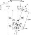
图2是表示本实施方式涉及的头相对于盘的配置的一个例子的示意图。FIG. 2 is a schematic diagram showing an example of the arrangement of the head with respect to the disk according to the present embodiment.

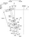
图3是表示将中间部定位于了半径位置的情况下的写入头和两个读取头的几何配置的一个例子的示意图。3 is a schematic diagram showing an example of the geometrical arrangement of the write head and the two read heads when the intermediate portion is positioned at the radial position.

图4是表示将中间部定位于了半径位置的情况下的写入头和两个读取头的几何配置的一个例子的图。FIG. 4 is a diagram showing an example of the geometrical arrangement of the write head and the two read heads when the intermediate portion is positioned at the radial position.

图5是表示将中间部定位于了半径位置的情况下的写入头和两个读取头的几何配置的一个例子的图。FIG. 5 is a diagram showing an example of the geometrical arrangement of the write head and the two read heads when the intermediate portion is positioned at the radial position.

图6是表示通常记录处理的一个例子的示意图。FIG. 6 is a schematic diagram showing an example of normal recording processing.

图7是表示瓦记录处理的一个例子的示意图。FIG. 7 is a schematic diagram showing an example of tile recording processing.

图8是表示通常记录于中周区域的数据的读处理的一个例子的示意图。FIG. 8 is a schematic diagram showing an example of read processing of data normally recorded in the mid-circumference area.

图9是表示瓦记录于中周区域的数据的读处理的一个例子的示意图。FIG. 9 is a schematic diagram showing an example of a read process of data recorded on a tile in a mid-circumference area.

图10是表示通常记录于外周区域的数据的读处理的一个例子的示意图。FIG. 10 is a schematic diagram showing an example of read processing of data normally recorded in the outer peripheral area.

图11是表示瓦记录于外周区域的数据的读处理的一个例子的示意图。FIG. 11 is a schematic diagram showing an example of read processing of data recorded on the outer peripheral area.

图12是表示通常记录于内周区域的数据的读处理的一个例子的示意图。FIG. 12 is a schematic diagram showing an example of read processing of data normally recorded in the inner peripheral area.

图13是表示瓦记录于内周区域的数据的读处理的一个例子的示意图。FIG. 13 is a schematic diagram showing an example of read processing of data recorded on the inner peripheral area.

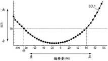
图14是表示通过交叉磁道间隔为比最小值大的值的两个读取头读取了预定磁道的情况下的位错误率相对于这些读取头的偏移量的变化的一个例子的示意图。14 is a schematic diagram showing an example of a change in the bit error rate with respect to the offsets of the read heads when a predetermined track is read by two read heads whose cross-track spacing is greater than the minimum value .

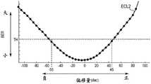
图15是表示通过交叉磁道间隔为最小值的两个读取头读取了预定磁道的情况下的位错误率相对于这些读取头的偏移量的变化的一个例子的示意图。15 is a schematic diagram showing an example of a change in the bit error rate with respect to the offsets of the read heads when a predetermined track is read by two read heads whose cross-track spacing is the minimum value.

图16是表示读取率相对于半径位置的变化的一个例子的示意图。FIG. 16 is a schematic diagram showing an example of a change in the read rate with respect to the radial position.

图17是表示本实施方式涉及的通常记录区域和瓦记录区域的配置的一个例子的示意图。FIG. 17 is a schematic diagram showing an example of the arrangement of the normal recording area and the tile recording area according to the present embodiment.

图18是表示本实施方式涉及的写处理方法的一个例子的流程图。FIG. 18 is a flowchart showing an example of a write processing method according to the present embodiment.

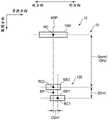
图19是表示将读取头定位于了半径位置的情况下的写入头和三个读取头的几何配置的一个例子的示意图。FIG. 19 is a schematic diagram showing an example of the geometric arrangement of the write head and the three read heads when the read head is positioned at the radial position.

图20是将读取头定位于了半径位置的情况下的写入头和三个读取头的几何配置的一个例子的示意图。FIG. 20 is a schematic diagram of an example of the geometric arrangement of the write head and the three read heads when the read head is positioned at the radial position.

图21是表示将读取头定位于了半径位置的情况下的写入头和三个读取头的几何配置的一个例子的示意图。21 is a schematic diagram showing an example of the geometrical arrangement of the write head and the three read heads when the read head is positioned at the radial position.

图22是表示变形例2涉及的头相对于盘的配置的一个例子的示意图。FIG. 22 is a schematic diagram showing an example of the arrangement of the head with respect to the disk according to Modification 2. FIG.

图23是表示变形例2涉及的将中间部定位于了半径位置的情况下的写入头和两个读取头的几何配置的一个例子的示意图。23 is a schematic diagram showing an example of the geometrical arrangement of the write head and the two read heads when the intermediate portion is positioned at the radial position according to Modification 2. FIG.

图24是表示变形例2涉及的将中间部定位于了半径位置的情况下的写入头和两个读取头的几何配置的一个例子的示意图。24 is a schematic diagram showing an example of the geometrical arrangement of the write head and the two read heads when the intermediate portion is positioned at the radial position according to Modification 2. FIG.

图25是表示变形例2涉及的将中间部定位于了半径位置的情况下的写入头和两个读取头的几何配置的一个例子的示意图。25 is a schematic diagram showing an example of the geometrical arrangement of the write head and the two read heads when the intermediate portion is positioned at the radial position according to Modification 2. FIG.

图26是表示变形例2涉及的将中间部定位于了半径位置的情况下的写入头和两个读取头的几何配置的一个例子的示意图。26 is a schematic diagram showing an example of the geometrical arrangement of the write head and the two read heads when the intermediate portion is positioned at the radial position according to Modification 2. FIG.

图27是表示变形例2涉及的通常记录区域和瓦记录区域的配置的一个例子的示意图。27 is a schematic diagram showing an example of the arrangement of the normal recording area and the tile recording area according to Modification 2. FIG.

具体实施方式Detailed ways

以下,参照附图对实施方式进行说明。此外,附图是一个例子,并不限定发明的范围。Hereinafter, embodiments will be described with reference to the drawings. In addition, the drawings are examples and do not limit the scope of the invention.

(实施方式)(Embodiment)

图1是表示实施方式涉及的磁盘装置1的结构的框图。FIG. 1 is a block diagram showing a configuration of amagnetic disk device 1 according to the embodiment.

磁盘装置1具备后述的头盘组件(HDA)、驱动器IC20、头放大器集成电路(以下记载为头放大器IC或者前置放大器)30、易失性存储器70、非易失性存储器80、缓冲存储器(缓存)90以及作为一个芯片的集成电路的系统控制器130。另外,磁盘装置1与主机系统(主机)100连接。磁盘装置1例如是二维记录(Two-Dimensional Magnetic Recording:TDMR)方式的磁盘装置。Themagnetic disk device 1 includes a head disk assembly (HDA) to be described later, adriver IC 20 , a head amplifier integrated circuit (hereinafter referred to as a head amplifier IC or a preamplifier) 30 , avolatile memory 70 , anonvolatile memory 80 , and a buffer memory (cache) 90 andsystem controller 130 as an integrated circuit of one chip. In addition, themagnetic disk device 1 is connected to a host system (host) 100 . Themagnetic disk device 1 is, for example, a magnetic disk device of a two-dimensional recording (Two-Dimensional Magnetic Recording: TDMR) method.

HAD具有磁盘(以下有时也称为盘)10、主轴马达(SPM)12、搭载头15的臂13以及音圈马达(VCM)14。盘10安装于主轴马达12,通过主轴马达12的驱动进行旋转。臂13和VCM14构成致动器。致动器通过臂13利用VCM14的旋转驱动来绕旋转轴(或者轴承)RAX进行旋转,从而将搭载于臂13的头15移动控制到盘10的预定位置。换言之,头15通过绕旋转轴RAX进行旋转来在盘10上移动。盘10和头15也可以设置有两个以上的数量。The HAD includes a magnetic disk (hereinafter sometimes referred to as a disk) 10 , a spindle motor (SPM) 12 , anarm 13 on which ahead 15 is mounted, and a voice coil motor (VCM) 14 . Thedisk 10 is attached to thespindle motor 12 and is rotated by the drive of thespindle motor 12 . Thearm 13 and the VCM 14 constitute an actuator. The actuator rotates around the rotation axis (or bearing) RAX by the rotation drive of the VCM 14 by thearm 13 , thereby controlling the movement of thehead 15 mounted on thearm 13 to a predetermined position of thedisk 10 . In other words, thehead 15 moves on thedisk 10 by rotating about the rotation axis RAX. Thedisk 10 and thehead 15 may also be provided in two or more numbers.

盘10对其能够写入数据的区域分配有能够由用户利用的用户数据区域10a、在将从主机100等传送来的数据(或者命令)写入到用户数据区域10a的预定区域之前暂时性地对其进行保持的媒体缓存(或者有时也称为媒体缓存区域)10b以及写入系统管理所需要的信息的系统区10c。以下,将盘10的从内周朝向外周的方向或者盘10的从外周朝向内周的方向称为半径方向。在半径方向上,将从内周朝向外周的方向称为外方向(外侧),将从内周朝向外周的方向称为内方向(内侧)。将盘10的与半径方向正交的方向称为圆周方向。圆周方向相当于沿着盘10的圆周的方向。另外,有时也将盘10的半径方向的预定位置称为半径位置,将盘10的圆周方向的预定位置称为圆周位置。有时也将半径位置和圆周位置一并简称为位置。盘10按半径方向上的预定范围而被区分为多个区域(以下有时也称为分区(zone))。分区可以按半径方向上的预定范围而被区分为多个区域(以下有时也称为带区域)。在带区域可以写入多个磁道。磁道包括多个扇区。另外,有时也将在半径方向上对盘10进行区分而得到的区域称为半径区域。半径区域包括分区、带区域以及磁道等。此外,“磁道”以在盘10的半径方向上区分而得到的多个区域中的一个区域、预定的半径位置处的头15的路径、在盘10的圆周方向上延伸的数据、在预定的半径位置的磁道所写入的1周量的数据、在磁道所写入的数据、其他各种含义来使用。“扇区”以在圆周方向上对磁道进行区分而得到的多个区域中的一个区域、在盘10的预定位置所写入的数据、在扇区所写入的数据、其他各种含义来使用。有时也将“磁道的半径方向上的宽度”称为“磁道宽度”。将“通过预定磁道中的磁道宽度的中心位置的路径”称为“磁道中央”。“用户数据区域”这一术语既有时以“用户数据区域的一部分”这一含义来使用,也有时也“多个用户数据区域中的一个用户数据区域”这一含义来使用,还有时以“多个用户数据区域中的几个用户数据区域”这一含义来使用,又有时以“盘10的全部用户数据区域”这一含义来使用。“媒体缓存”这一术语既有时以“媒体缓存的一部分”这一含义来使用,也有时以“多个媒体缓存中的一个媒体缓存”这一含义来使用,还有时以“多个媒体缓存中的几个媒体缓存”这一含义来使用,又有时以“盘10的全部媒体缓存”这一含义来使用。Thedisk 10 is assigned auser data area 10a usable by a user to an area to which data can be written, and temporarily before writing data (or commands) transferred from thehost 100 or the like to a predetermined area of theuser data area 10a A media buffer (or sometimes referred to as a media buffer area) 10b for holding it and asystem area 10c for writing information required for system management. Hereinafter, the direction from the inner circumference toward the outer circumference of thedisk 10 or the direction from the outer circumference toward the inner circumference of thedisk 10 is referred to as the radial direction. In the radial direction, the direction from the inner circumference toward the outer circumference is referred to as the outer direction (outside), and the direction from the inner circumference toward the outer circumference is referred to as the inner direction (inside). The direction orthogonal to the radial direction of thedisk 10 is referred to as the circumferential direction. The circumferential direction corresponds to the direction along the circumference of thedisk 10 . In addition, the predetermined position in the radial direction of thedisk 10 may be referred to as a radial position, and the predetermined position in the circumferential direction of thedisk 10 may be referred to as a circumferential position. The radial position and the circumferential position are also sometimes simply referred to as positions. Thedisk 10 is divided into a plurality of zones (hereinafter sometimes referred to as zones) in a predetermined range in the radial direction. The partition can be divided into a plurality of regions (hereinafter sometimes also referred to as band regions) within a predetermined range in the radial direction. Multiple tracks can be written in the tape area. A track includes multiple sectors. In addition, an area obtained by dividing thedisk 10 in the radial direction may be referred to as a radial area. Radius regions include partitions, band regions, and tracks. In addition, the "track" is one of a plurality of regions divided in the radial direction of thedisk 10, a path of thehead 15 at a predetermined radial position, data extending in the circumferential direction of thedisk 10, a predetermined It is used for the data written in one revolution of the track at the radial position, the data written on the track, and various other meanings. "Sector" refers to one of a plurality of regions obtained by dividing a track in the circumferential direction, data written in a predetermined position of thedisk 10, data written in a sector, and various other meanings. use. The "width in the radial direction of the track" is sometimes referred to as the "track width". "The path passing through the center position of the track width in the predetermined track" is referred to as the "track center". The term "user data area" is sometimes used in the sense of "a portion of a user data area", sometimes "a user data area of a plurality of user data areas", and sometimes " It is used in the sense of "several user data areas out of a plurality of user data areas", and is sometimes used in the sense of "all user data areas of thedisc 10". The term "media cache" is sometimes used in the sense of "part of a media cache", sometimes in the sense of "a media cache of multiple media caches", and sometimes in the sense of "multiple media caches" It is used in the sense of "several media caches in the disk", and sometimes in the sense of "all media caches of thedisk 10".

头15将滑块作为主体,具备安装于该滑块的写入头15W和读取头15R。写入头15W向盘10写入数据。读取头15R读取记录于盘10的数据。读取头15R具有多个读取头、例如两个读取头15R1和15R2。读取头15R1例如设置在距写入头15W最远的位置。读取头15R2例如设置在距写入头15W的距离比读取头15R1距写入头15W的距离近的位置。换言之,读取头15R2位于写入头15W和读取头15R1之间。此外,读取头15R也可以具有3个以上的读取头。以下,既有时将多个读取头、例如两个读取头15R1、15R2一并称为读取头15R,也有时将多个读取头、例如读取头15R1和15R2中的任一个简称为读取头15R。Thehead 15 has a slider as a main body, and includes awrite head 15W and aread head 15R attached to the slider. Thewrite head 15W writes data to thedisk 10 . The readhead 15R reads data recorded on thedisc 10 . The readhead 15R has a plurality of read heads, for example, two read heads 15R1 and 15R2. The read head 15R1 is provided, for example, at the farthest position from thewrite head 15W. The read head 15R2 is provided, for example, at a position closer to thewrite head 15W than the read head 15R1 is to thewrite head 15W. In other words, the read head 15R2 is located between thewrite head 15W and the read head 15R1. In addition, theread head 15R may have three or more read heads. Hereinafter, a plurality of read heads, such as the two read heads 15R1 and 15R2, may be collectively referred to as theread head 15R, and a plurality of read heads, such as the read heads 15R1 and 15R2, may be referred to for short. For the readhead 15R.

图2是表示本实施方式涉及的头15相对于盘10的配置的一个例子的示意图。如图2所示,在圆周方向上,将盘10旋转的方向称为旋转方向。此外,在图2所示的例子中,旋转方向由逆时针方向表示,但也可以是相反方向(顺时针方向)。FIG. 2 is a schematic diagram showing an example of the arrangement of thehead 15 with respect to thedisk 10 according to the present embodiment. As shown in FIG. 2 , in the circumferential direction, the direction in which thedisk 10 rotates is referred to as the rotation direction. In addition, in the example shown in FIG. 2, although the rotation direction is shown by the counterclockwise direction, it may be the opposite direction (clockwise direction).

在图2所示的例子中,用户数据区域10a被区分为位于内方向的内周区域IR、位于外方向的外周区域OR以及位于内周区域IR与外周区域OR之间的中周区域MR。在用户数据区域10a中,内周区域IR相当于位于最内周的区域,外周区域OR相当于位于最外周的区域。在用户数据区域10a中,中周区域MR在内周区域IR的外方向上与内周区域IR相邻,外周区域OR在中周区域MR的外方向上与中周区域MR相邻。换言之,在用户数据区域10a中,中周区域MR在外周区域OR的内方向上与外周区域OR相邻,内周区域IR在中周区域MR的内方向上与中周区域MR相邻。在此,“相邻”当然包括数据、物体、区域以及空间等相接地排列,也包括隔开预定间隔来排列。在图2中,用户数据区域10a包括半径位置IRP、半径位置MRP以及半径位置ORP。半径位置IRP相当于用户数据区域10a的最内周的半径位置。半径位置ORP相当于用户数据区域10a的最外周的半径位置。半径位置MRP相当于用户数据区域10a的半径方向上的宽度中心的半径位置、例如半径位置IRP和ORP的中间的半径位置。此外,半径位置MRP也可以相当于盘10的半径方向上的宽度中心的半径位置。在图2所示的例子中,在头15配置于半径位置MRP的情况下,扭斜角θsw例如为0°。In the example shown in FIG. 2, theuser data area 10a is divided into an inner peripheral area IR located in the inner direction, an outer peripheral area OR located in the outer direction, and a middle peripheral area MR located between the inner peripheral area IR and the outer peripheral area OR. In theuser data area 10a, the inner circumference area IR corresponds to the area located on the innermost circumference, and the outer circumference area OR corresponds to the area located at the outermost circumference. In theuser data region 10a, the middle circumferential region MR is adjacent to the inner circumferential region IR in the outer direction of the inner circumferential region IR, and the outer circumferential region OR is adjacent to the middle circumferential region MR in the outer direction of the middle circumferential region MR. In other words, in theuser data region 10a, the middle circumferential region MR is adjacent to the outer circumferential region OR in the inner direction of the outer circumferential region OR, and the inner circumferential region IR is adjacent to the middle circumferential region MR in the inner direction of the middle circumferential region MR. Here, "adjacent" naturally includes that data, objects, regions, spaces, etc. are arranged adjacent to each other, and also includes arrangement at predetermined intervals. In FIG. 2, theuser data area 10a includes a radial position IRP, a radial position MRP, and a radial position ORP. The radial position IRP corresponds to the radial position of the innermost circumference of theuser data area 10a. The radial position ORP corresponds to the radial position of the outermost periphery of theuser data area 10a. The radial position MRP corresponds to the radial position of the width center of theuser data area 10a in the radial direction, for example, the radial position between the radial positions IRP and ORP. In addition, the radial position MRP may correspond to the radial position of the width center of thedisk 10 in the radial direction. In the example shown in FIG. 2 , when thehead 15 is arranged at the radial position MRP, the skew angle θsw is, for example, 0°.

虽未图示,但盘10具有多个伺服模式。多个伺服模式在盘10的半径方向上呈放射状延伸,在圆周方向上空开预定间隔而离散地配置。伺服模式包含用于将头15定位于盘10的预定位置的伺服数据等。在伺服模式以外的用户数据区域10a可以写入伺服数据以外的数据(有时也称为用户数据)。此外,有时也将“伺服模式”称为“伺服区域”或者“伺服数据”。伺服模式例如包括前导码(Preamble)PRB、伺服标记(Servo Mark)SM、格雷码(Gray Code)GC、PAD PD、突发数据以及区位码(Post Code)PC。此外,伺服模式也可以不包括区位码PC。Although not shown, thedisk 10 has a plurality of servo patterns. The plurality of servo patterns extend radially in the radial direction of thedisk 10 and are discretely arranged at predetermined intervals in the circumferential direction. The servo pattern includes servo data and the like for positioning thehead 15 at a predetermined position of thedisc 10 . Data other than servo data (sometimes referred to as user data) can be written in theuser data area 10a other than the servo pattern. In addition, the "servo pattern" is sometimes referred to as a "servo area" or "servo data". Servo patterns include, for example, Preamble PRB, Servo Mark SM, Gray Code GC, PAD PD, Burst Data, and Post Code PC. In addition, the servo pattern may not include the area code PC.

在寻道时,头15通过致动器(臂13和VCM14)绕旋转轴RAX进行旋转来在盘10的水平面内滑动。在图2所示的例子中,头15在配置于半径位置MRP的情况下,位于沿着圆周方向的位置。头15通过随着致动器的旋转而绕旋转轴RAX进行旋转,从而在盘10上相对于圆周方向倾斜。During the seek, thehead 15 slides in the horizontal plane of thedisk 10 by the rotation of the actuators (arm 13 and VCM 14) about the rotation axis RAX. In the example shown in FIG. 2, when thehead 15 is arrange|positioned at the radial position MRP, it is located in the position along the circumferential direction. Thehead 15 is inclined with respect to the circumferential direction on thedisk 10 by being rotated about the rotation axis RAX in accordance with the rotation of the actuator.

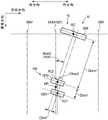
图3是表示将中间部MP定位于了半径位置MRP的情况下的写入头15W和两个读取头15R1、15R2的几何配置的一个例子的示意图。在图3中示出写入头15W的中心部WC、读取头15R1的中心部RC1、读取头15R2的中心部RC2、位于读取头15R1的中心部RC1和读取头15R2的中心部RC2的圆周方向上的中间的中间部MP。以下,有时也将多个读取头15R中的两个读取头15R之间的圆周方向上的间隔称为循着磁道间隔(Down Track Separation:DTS)。有时也将多个读取头15R中的两个读取头15R之间的半径方向上的间隔称为交叉磁道间隔(CrossTrack Separation:CTS)。有时也将读取头15R与写入头15W的间隔、例如读取头15R1的中心部RC1与写入头15W的中心部WC之间的圆周方向上的间隔、读取头15R2的中心部RC2与写入头15W的中心部WC之间的圆周方向上的间隔以及中间部MP与写入头15W的中心部WC之间的圆周方向上的间隔称为读/写间隙Grw。为了便于说明,有时也将“写入头的中心部”和“写入头的各部”简称为“写入头”,将“读取头的中心部”、“多个读取头中的两个读取头的中间部”以及“读取头的各部”简称为“读取头”。将多个读取头15R和多个读取头15R中的两个读取头15R的中间部中的任一个配置或者定位于作为对象的位置(以下有时也称为对象位置)来进行数据的写/读。例如,将中间部MP配置或者定位于对象位置来进行数据的写/读。有时也将“将中间部MP配置或者定位于对象位置”表现为“将读取头15R配置或者定位于对象位置”。此外,也可以将“将多个读取头15R中的一个读取头15R配置或者定位于对象位置”表现为“将读取头15R配置或者定位于对象位置”。例如,有时也将“将中间部MP配置或者定位于对象位置来进行数据的写/读”表现为“进行写/读”。此外,也可以将“将多个读取头15R中的一个读取头15R配置或者定位于对象位置来进行数据的写/读”表现为“进行写/读”。另外,也可以将“将多个读取头15R配置或者定位于对象位置来进行数据的写/读”表现为“进行写/读”。3 is a schematic diagram showing an example of the geometric arrangement of thewrite head 15W and the two read heads 15R1 and 15R2 when the intermediate portion MP is positioned at the radial position MRP. 3 shows the center portion WC of thewrite head 15W, the center portion RC1 of the read head 15R1, the center portion RC2 of the read head 15R2, the center portion RC1 of the read head 15R1, and the center portion of the read head 15R2 The middle part MP in the circumferential direction of RC2. Hereinafter, the interval in the circumferential direction between two readheads 15R among the plurality of read heads 15R may be referred to as a down track separation (DTS). The interval in the radial direction between the two readheads 15R among the plurality of read heads 15R is also sometimes referred to as a cross track separation (Cross Track Separation: CTS). The space between the readhead 15R and thewrite head 15W, for example, the space in the circumferential direction between the center portion RC1 of the read head 15R1 and the center portion WC of thewrite head 15W, and the center portion RC2 of the read head 15R2 The space in the circumferential direction from the center portion WC of thewrite head 15W and the space in the circumferential direction between the intermediate portion MP and the center portion WC of thewrite head 15W are referred to as read/write gap Grw. For convenience of description, the "central part of the write head" and "each part of the write head" are sometimes abbreviated as "the write head", and the "central part of the read head" and "two of the plurality of read heads" The middle part of each read head" and the "each part of the read head" are simply referred to as "read heads". The plurality of read heads 15R and any one of the intermediate portions of the two readheads 15R among the plurality of read heads 15R are arranged or positioned at the target position (hereinafter sometimes referred to as the target position) to perform data transfer. write/read. For example, data writing/reading is performed by arranging or positioning the intermediate part MP at the target position. "The intermediate portion MP is arranged or positioned at the target position" is sometimes expressed as "thepickup 15R is positioned or positioned at the target position". In addition, "arranging or positioning one of the reading heads 15R at the target position" may be expressed as "arranging or positioning thereading head 15R at the target position". For example, "writing/reading data by arranging or positioning the intermediate part MP at a target position" may be expressed as "writing/reading". In addition, "to perform writing/reading of data by arranging or positioning one of the plurality of reading heads 15R at a target position" may be expressed as "performing writing/reading". In addition, "writing/reading data by arranging or positioning a plurality of read heads 15R at target positions" may be expressed as "writing/reading".

在图3所示的例子中,在将中间部MP配置于了中间位置MRP的情况下,写入头15W、读取头15R1、读取头15R2以及中间部MP沿着圆周方向排列。在将中间部MP配置于了半径位置MRP的情况下,读/写间隙Grw为距离Grwm1。在将半径位置MRP配置于了中间部MP的情况下,循着磁道间隔(DTS)是距离DSm1。例如,读/写间隙Grw=Grwm1比循着磁道间隔=DSm1大。In the example shown in FIG. 3, when the intermediate part MP is arranged at the intermediate position MRP, thewrite head 15W, the reading head 15R1, the reading head 15R2, and the intermediate part MP are arranged in the circumferential direction. When the intermediate portion MP is arranged at the radial position MRP, the read/write gap Grw is the distance Grwm1. When the radial position MRP is arranged in the intermediate portion MP, the tracking space (DTS) is the distance DSm1. For example, the read/write gap Grw=Grwm1 is larger than the following track spacing=DSm1.

在图3所示的例子中,在将中间部MP配置于了半径位置MRP的情况下,写入头15W、读取头15R1、读取头15R2以及中间部MP在半径方向上不错开。换言之,在图3中,写入头15W、读取头15R1、读取头15R2以及中间部MP位于半径位置MRP。也即是,在图3中,头15的扭斜角θsw为0°。在将中间部MP配置于了半径位置MRP的情况下,交叉磁道间隔(CTS)为最小值、例如距离CSm0=0。此外,在将中间部MP配置于了半径位置MRP的情况下,写入头15W、读取头15R1、读取头15R2以及中间部MP也可以分别在半径方向上错开。以下,有时也将“设置于一个头15的多个读取头15R中的至少一对的两个读取头的交叉磁道间隔在盘10中、例如在用户数据区域10a中成为最小值的半径位置”称为“基准位置”。在图3所示的例子中,半径位置MRP相当于基准位置BP。In the example shown in FIG. 3, when the intermediate part MP is arranged at the radial position MRP, thewrite head 15W, the reading head 15R1, the reading head 15R2, and the intermediate part MP are not spaced apart in the radial direction. In other words, in FIG. 3, thewrite head 15W, the read head 15R1, the read head 15R2, and the intermediate portion MP are located at the radial position MRP. That is, in FIG. 3 , the skew angle θsw of thehead 15 is 0°. When the intermediate portion MP is arranged at the radial position MRP, the cross-track spacing (CTS) is the minimum value, for example, the distance CSm0=0. In addition, when the intermediate portion MP is arranged at the radial position MRP, thewrite head 15W, the reading head 15R1, the reading head 15R2, and the intermediate portion MP may be shifted in the radial direction, respectively. Hereinafter, "the cross-track interval of at least one pair of two heads of the plurality ofheads 15R provided in onehead 15 may be a radius that is the minimum value in thedisc 10, for example, in theuser data area 10a. position" is called the "reference position". In the example shown in FIG. 3 , the radial position MRP corresponds to the reference position BP.

图4是表示将中间部MP定位于了半径位置IRP的情况下的写入头15W和两个读取头15R1、15R2的几何配置的一个例子的图。FIG. 4 is a diagram showing an example of the geometric arrangement of thewrite head 15W and the two read heads 15R1 and 15R2 when the intermediate portion MP is positioned at the radial position IRP.

在图4所示的例子中,在将中间部MP配置于了半径位置IRP的情况下,写入头15W、读取头15R1、读取头15R2以及中间部MP相对于按照圆周方向延长的轴以扭斜角θsw=θswi1向内方向倾斜。在将中间部MP配置于了半径位置IRP的情况下,读/写间隙Grw为距离Grwi1。在将中间部MP配置于了半径位置IRP的情况下,循着磁道间隔(DTS)为距离DSi1。In the example shown in FIG. 4 , when the intermediate portion MP is arranged at the radial position IRP, the writinghead 15W, the reading head 15R1 , the reading head 15R2 and the intermediate portion MP are relative to the axis extending in the circumferential direction. It is inclined inward at a skew angle θsw=θswi1. When the intermediate portion MP is arranged at the radial position IRP, the read/write gap Grw is the distance Grwi1. When the intermediate portion MP is arranged at the radial position IRP, the tracking space (DTS) is the distance DSi1.

在图4所示的例子中,在将中间部MP配置于了半径位置IRP的情况下,写入头15W、读取头15R1、读取头15R2以及中间部MP在半径方向上错开。此外,在将中间部MP配置于了半径位置IRP的情况下,写入头15W、读取头15R1,读取头15R2以及中间部MP也可以分别在半径方向上不错开。在将中间部MP配置于了半径位置IRP的情况下,交叉磁道间隔(CTS)为距离CSi1。交叉磁道间隔CSi1的绝对值是将头15、例如中间部MP定位在用户数据区域10a内的情况下的交叉磁道间隔的绝对值的最大值。此外,交叉磁道间隔CSi1的绝对值也可以不是将头15、例如中间部MP定位在用户数据区域10a内的情况下的交叉磁道间隔的绝对值的最大值。以下,有时也将“交叉磁道间隔的绝对值”简称为“交叉磁道间隔”。In the example shown in FIG. 4, when the intermediate part MP is arranged at the radial position IRP, thewrite head 15W, the reading head 15R1, the reading head 15R2, and the intermediate part MP are shifted in the radial direction. Further, when the intermediate portion MP is arranged at the radial position IRP, thewrite head 15W, the reading head 15R1, the reading head 15R2, and the intermediate portion MP may not be spaced apart in the radial direction, respectively. When the intermediate portion MP is arranged at the radial position IRP, the cross-track spacing (CTS) is the distance CSi1. The absolute value of the cross-track interval CSi1 is the maximum value of the absolute value of the cross-track interval when thehead 15, eg, the middle part MP, is positioned in theuser data area 10a. In addition, the absolute value of the cross-track interval CSi1 may not be the maximum value of the absolute value of the cross-track interval when thehead 15, eg, the middle part MP, is positioned in theuser data area 10a. Hereinafter, the "absolute value of the cross-track spacing" may be simply referred to as the "cross-track spacing".

图5是表示将中间部MP定位于了半径位置ORP的情况下的写入头15W和两个读取头15R1、15R2的几何配置的一个例子的图。FIG. 5 is a diagram showing an example of the geometric arrangement of thewrite head 15W and the two read heads 15R1 and 15R2 when the intermediate portion MP is positioned at the radial position ORP.

在图5所示的例子中,在将中间部MP配置于了半径位置ORP的情况下,写入头15W、读取头15R1、读取头15R2以及中间部MP相对于按照圆周方向延长的轴以扭斜角θsw=θswo1向外方向倾斜。例如,扭斜角θswo1与扭斜角θswi1相同。“相同”、“同一”、“一致”以及“同等”等的术语当然包括完全相同这一含义,也包括在可视为实质上相同的程度上不同这一含义。此外,扭斜角θswo1也可以与扭斜角θswi不同。扭斜角θswo1例如也可以比扭斜角θswi大。扭斜角θswo1例如也可以比扭斜角θswi小。在将中间部MP配置于了半径位置ORP的情况下,读/写间隙Grw为距离Grwo1。在将中间部MP配置于了半径位置ORP的情况下,循着磁道间隔(DTS)为距离DSo1。In the example shown in FIG. 5 , when the intermediate portion MP is arranged at the radial position ORP, the writinghead 15W, the reading head 15R1 , the reading head 15R2 , and the intermediate portion MP are relative to the axis extending in the circumferential direction. It is inclined in the outward direction at the skew angle θsw=θswo1. For example, the skew angle θswo1 is the same as the skew angle θswi1. Terms such as "same", "identical", "identical" and "equivalent" certainly include the meaning of being identical, as well as the meaning of being different to the extent that they can be considered substantially the same. Also, the skew angle θswo1 may be different from the skew angle θswi. The skew angle θswo1 may be larger than the skew angle θswi, for example. The skew angle θswo1 may be smaller than the skew angle θswi, for example. When the intermediate portion MP is arranged at the radial position ORP, the read/write gap Grw is the distance Grwo1. When the intermediate portion MP is arranged at the radial position ORP, the tracking space (DTS) is the distance DSo1.

在图5所示的例子中,在将中间部MP配置于了半径位置ORP的情况下,写入头15W、读取头15R1、读取头15R2以及中间部MP在半径方向上错开。此外,在将中间部MP配置于了半径位置ORP的情况下,写入头15W、读取头15R1、读取头15R2以及中间部MP也可以分别在半径方向上不错开。在将中间部MP配置于了半径位置ORP的情况下,交叉磁道间隔(CTS)为距离CSo1。交叉磁道间隔CSo1和交叉磁道间隔CSi1相同。此外,交叉磁道间隔CSo1和交叉磁道间隔CSi1也可以不同。例如,交叉磁道间隔CSo1也可以比交叉磁道间隔CSi1大。例如,交叉磁道间隔CSo1也可以比交叉磁道间隔CSi1小。交叉磁道间隔CSo1是将头15、例如中间部MP定位在用户数据区域10a内的情况下的交叉磁道间隔的最大值。例如,在交叉磁道间隔CSo1和交叉磁道间隔CSi1相同的情况下,交叉磁道间隔CSo1为交叉磁道间隔的最大值。例如,在交叉磁道间隔CSo1比交叉磁道间隔Csi1大的情况下,交叉磁道间隔CSo1为交叉磁道间隔的最大值。此外,交叉磁道间隔CSo1也可以不是将头15、例如中间部MP定位在用户数据区域10a内的情况下的交叉磁道间隔的最大值。例如,在交叉磁道间隔CSo1比交叉磁道间隔CSi1小的情况下,交叉磁道间隔CSo1不是最大值。In the example shown in FIG. 5 , when the intermediate portion MP is arranged at the radial position ORP, thewrite head 15W, the reading head 15R1 , the reading head 15R2 , and the intermediate portion MP are shifted in the radial direction. Further, when the intermediate portion MP is arranged at the radial position ORP, thewrite head 15W, the reading head 15R1, the reading head 15R2, and the intermediate portion MP may not be spaced apart in the radial direction, respectively. When the intermediate portion MP is arranged at the radial position ORP, the cross-track spacing (CTS) is the distance CSo1. The cross-track spacing CSo1 and the cross-track spacing CSi1 are the same. Also, the cross-track spacing CSo1 and the cross-track spacing CSi1 may be different. For example, the cross-track spacing CSo1 may be larger than the cross-track spacing CSi1. For example, the cross-track spacing CSo1 may be smaller than the cross-track spacing CSi1. The cross-track interval CSo1 is the maximum value of the cross-track interval when thehead 15, eg, the middle portion MP, is positioned within theuser data area 10a. For example, when the cross-track interval CSo1 and the cross-track interval CSi1 are the same, the cross-track interval CSo1 is the maximum value of the cross-track interval. For example, when the cross-track interval CSo1 is larger than the cross-track interval Csi1, the cross-track interval CSo1 is the maximum value of the cross-track interval. In addition, the cross-track interval CSo1 may not be the maximum value of the cross-track interval when thehead 15, eg, the middle portion MP, is positioned in theuser data area 10a. For example, when the cross-track interval CSo1 is smaller than the cross-track interval CSi1, the cross-track interval CSo1 is not the maximum value.

驱动器IC20按照系统控制器130(详细而言为后述的MPU40)的控制,对SPM12和VCM14的驱动进行控制。Thedriver IC 20 controls the driving of theSPM 12 and the VCM 14 in accordance with the control of the system controller 130 (specifically, theMPU 40 to be described later).

头放大器IC(前置放大器)30具备读放大器和写驱动器。读放大器对从盘10读出的读信号进行放大,并输出至系统控制器130(详细而言为后述的读/写(R/W)通道50)。写驱动器向头15输出与从R/W通道50输出的写数据相应的写电流。The head amplifier IC (pre-amplifier) 30 includes a read amplifier and a write driver. The read amplifier amplifies the read signal read out from thedisk 10 and outputs it to the system controller 130 (specifically, a read/write (R/W)channel 50 to be described later). The write driver outputs a write current corresponding to the write data output from the R/W channel 50 to thehead 15 .

易失性存储器70是当电力供给被切断时、所保存的数据会丢失的半导体存储器。易失性存储器70保存磁盘装置1的各部的处理所需要的数据等。易失性存储器70例如是DRAM(Dynamic Random Access Memory,动态随机访问存储器)或者SDRAM(SynchronousDynamic Random Access Memory,同步动态随机访问存储器)。Thevolatile memory 70 is a semiconductor memory whose stored data is lost when the power supply is cut off. Thevolatile memory 70 stores data and the like necessary for the processing of each part of themagnetic disk device 1 . Thevolatile memory 70 is, for example, DRAM (Dynamic Random Access Memory, dynamic random access memory) or SDRAM (Synchronous Dynamic Random Access Memory, synchronous dynamic random access memory).

非易失性存储器80是即使电力供给被切断、也记录所保存的数据的半导体存储器。非易失性存储器80例如是NOR型或者NAND型的闪速ROM(Flash Read Only Memory(闪速只读存储器):FROM)。Thenonvolatile memory 80 is a semiconductor memory that records stored data even when the power supply is cut off. Thenonvolatile memory 80 is, for example, a NOR-type or NAND-type flash ROM (Flash Read Only Memory: FROM).

缓冲存储器90是暂时性地记录在磁盘装置1与主机100之间收发的数据等的半导体存储器。此外,缓冲存储器90也可以与易失性存储器70构成为一体。缓冲存储器90例如是DRAM、SRAM(Static Random Access Memory,静态随机访问存储器)、SDRAM、FeRAM(Ferroelectric Random Access memory,铁电随机访问存储器)或者MRAM(Magnetoresistive Random Access Memory,磁阻随机访问存储器)等。Thebuffer memory 90 is a semiconductor memory that temporarily records data and the like transmitted and received between themagnetic disk device 1 and thehost 100 . In addition, thebuffer memory 90 may be formed integrally with thevolatile memory 70 . Thebuffer memory 90 is, for example, DRAM, SRAM (Static Random Access Memory, static random access memory), SDRAM, FeRAM (Ferroelectric Random Access memory, ferroelectric random access memory), or MRAM (Magnetoresistive Random Access Memory, magnetoresistive random access memory), etc. .

系统控制器(控制器)130例如使用多个元件集成于单一芯片的被称为片上系统(System-on-a-Chip(SoC))的大规模集成电路(LSI)来实现。系统控制器130包括硬盘控制器(HDC)40、读/写(R/W)通道50以及微处理器(MPU)60等。HDC40、R/W通道50以及MPU60分别相互电连接。系统控制器130例如与驱动器IC20、头放大器IC30、易失性存储器70、非易失性存储器80、缓冲存储器90以及主机系统100等电连接。The system controller (controller) 130 is implemented using, for example, a large-scale integrated circuit (LSI) called a system-on-a-chip (SoC) in which a plurality of elements are integrated on a single chip. Thesystem controller 130 includes a hard disk controller (HDC) 40, a read/write (R/W)channel 50, a microprocessor (MPU) 60, and the like. TheHDC 40, the R/W channel 50, and theMPU 60 are electrically connected to each other, respectively. Thesystem controller 130 is electrically connected to, for example, thedriver IC 20 , thehead amplifier IC 30 , thevolatile memory 70 , thenonvolatile memory 80 , thebuffer memory 90 , thehost system 100 , and the like.

HDC40对数据的传送进行控制。HDC40例如按照来自后述的MPU60的指示,对主机100与盘10之间的数据的传送进行控制。HDC40例如与R/W通道50、MPU60、易失性存储器70、非易失性存储器80以及缓冲存储器90等电连接。TheHDC 40 controls the transfer of data. TheHDC 40 controls the transfer of data between thehost 100 and thedisk 10 in accordance with, for example, an instruction from theMPU 60 to be described later. TheHDC 40 is electrically connected to, for example, the R/W channel 50 , theMPU 60 , thevolatile memory 70 , thenonvolatile memory 80 , thebuffer memory 90 , and the like.

R/W通道50按照来自后述的MPU60的指示,执行从盘10传送至主机100的数据、例如读数据和从主机100传送的数据、例如写数据的信号处理。R/W通道50具有对写数据进行调制的电路或者功能。R/W通道50具有对读数据的信号品质进行测定的电路或者功能。R/W通道50例如与头放大器IC30、HDC40以及MPU60等电连接。The R/W channel 50 performs signal processing of data transferred from thedisk 10 to thehost 100 , such as read data, and data transferred from thehost 100 , such as write data, in accordance with an instruction from theMPU 60 , which will be described later. The R/W channel 50 has a circuit or function to modulate write data. The R/W channel 50 has a circuit or function for measuring the signal quality of read data. The R/W channel 50 is electrically connected to, for example, thehead amplifier IC 30 , theHDC 40 , theMPU 60 , and the like.

R/W通道50具有解调部510和解调部520。解调部510对由读取头15R1读取到的数据、例如伺服数据进行解调,将所解调的伺服数据输出至MPU60等。解调部520对由读取头15R2读取到的数据、例如伺服数据进行解调,将所解调的伺服数据输出至MPU60等。此外,在一个头15设置有三个以上的读取头15R的情况下,R/W通道50也可以具有分别与设置于一个头15的三个以上的读取头15R对应的三个以上的解调部。The R/W channel 50 has ademodulation unit 510 and a demodulation unit 520 . Thedemodulation unit 510 demodulates the data read by the read head 15R1, eg, servo data, and outputs the demodulated servo data to theMPU 60 or the like. The demodulation unit 520 demodulates the data read by the read head 15R2, eg, servo data, and outputs the demodulated servo data to theMPU 60 or the like. In addition, when onehead 15 is provided with three or more read heads 15R, the R/W channel 50 may have three or more solutions corresponding to the three or more read heads 15R provided on onehead 15, respectively. Tuning department.

MPU60是对磁盘装置1的各部进行控制的主控制器。MPU60经由驱动器IC20对VCM14进行控制,执行进行头15的定位的伺服控制。MPU60经由驱动器IC20对SPM12进行控制,使盘10旋转。MPU60对向盘10写入数据的写动作进行控制,并且,对从主机100传送的数据、例如写数据的保存目的地进行选择。另外,MPU60对从盘10读取数据的读动作进行控制,并且,对从盘10传送至主机100的数据、例如读数据的处理进行控制。另外,MPU60对记录数据的区域进行管理。MPU60与磁盘装置1的各部连接。MPU60例如与驱动器IC20、HDC40以及R/W通道50等电连接。TheMPU 60 is a main controller that controls each part of themagnetic disk device 1 . TheMPU 60 controls the VCM 14 via thedriver IC 20 and executes servo control for positioning thehead 15 . TheMPU 60 controls theSPM 12 via thedriver IC 20 to rotate thedisk 10 . TheMPU 60 controls the write operation for writing data to thedisk 10 and selects the storage destination of the data transferred from thehost 100 , for example, the write data. In addition, theMPU 60 controls the read operation of reading data from thedisk 10 , and also controls the data transferred from thedisk 10 to thehost 100 , for example, the processing of reading data. In addition, theMPU 60 manages the area in which data is recorded. TheMPU 60 is connected to each part of themagnetic disk device 1 . TheMPU 60 is electrically connected to, for example, thedriver IC 20 , theHDC 40 , the R/W channel 50 , and the like.

MPU60具有读/写控制部610和记录区域管理部620。MPU60在固件上执行各部、例如读/写控制部610和记录区域管理部620等的处理。此外,MPU60也可以作为电路来具有各部、例如读/写控制部610和记录区域管理部620等。TheMPU 60 has a read/write control unit 610 and a recordingarea management unit 620 . TheMPU 60 executes the processing of each unit, for example, the read/write control unit 610 and the recordingarea management unit 620, on the firmware. In addition, theMPU 60 may include various units as circuits, for example, the read/write control unit 610 and the recordingarea management unit 620 and the like.

读/写控制部610按照来自主机100的命令等,对从盘10读取数据的读处理和向盘10写入数据的写处理进行控制。读/写控制部610经由驱动器IC20对VCM14进行控制,将头15定位于盘10的预定位置,执行读处理或者写处理。The read/write control unit 610 controls a read process of reading data from thedisk 10 and a write process of writing data to thedisk 10 in accordance with a command from thehost 100 or the like. The read/write control unit 610 controls the VCM 14 via thedriver IC 20 , positions thehead 15 at a predetermined position on thedisk 10 , and executes read processing or write processing.

读/写控制部610例如以从预定磁道或者预定扇区在半径方向上空开预定间隔(间隙)来对与该磁道或者该扇区相邻的其他磁道(以下有时也称为相邻磁道)或者其他扇区(以下有时也称为相邻扇区)写入数据的通常记录(Conventional Magnetic Recording:CMR)型式执行写处理。“相邻磁道”包括“在预定磁道的外方向上与预定磁道相邻的磁道”、“在预定磁道的内方向上与预定磁道相邻的磁道”以及“在预定磁道的外方向和内方向上与预定磁道相邻的多个磁道”。“相邻扇区”包括“在预定扇区的外方向上与预定扇区相邻的扇区”、“在预定扇区的内方向上与预定扇区相邻的扇区”以及“在预定扇区的外方向和内方向上与预定扇区相邻的多个扇区”。以下,有时也将“以通常记录型式写入数据”称为“通常记录”、“执行通常记录处理”,或者简称为“写入”。The read/write control unit 610, for example, sets a predetermined interval (gap) in the radial direction from a predetermined track or a predetermined sector to other tracks (hereinafter sometimes referred to as adjacent tracks) or adjacent to the track or the sector. A conventional recording (Conventional Magnetic Recording: CMR) type of writing data in other sectors (hereinafter sometimes also referred to as adjacent sectors) performs write processing. The "adjacent track" includes "the track adjacent to the predetermined track in the outer direction of the predetermined track", "the track adjacent to the predetermined track in the inner direction of the predetermined track", and "in the outer and inner directions of the predetermined track" a plurality of tracks adjacent to a predetermined track". The "adjacent sector" includes "a sector adjacent to the predetermined sector in the outer direction of the predetermined sector", "sector adjacent to the predetermined sector in the inner direction of the predetermined sector", and "in the predetermined sector" A plurality of sectors adjacent to a predetermined sector in the outer and inner directions of the sector". Hereinafter, "writing data in the normal recording format" may also be referred to as "normal recording", "execution of normal recording processing", or simply "writing".

读/写控制部610以瓦记录(Shingled write Magnetic Recording:SMR、或者Shingled Write Recording:SWR)型式执行写处理,瓦记录型式是如下型式:在以顺序(sequential)的方式进行多个磁道的写入时,与前一个进行了写入的磁道的半径方向上的一部分重叠地对接下来要写入的磁道进行写入。以下,有时也将“以瓦记录型式写入数据”称为“瓦记录”或“执行瓦记录处理”,或者简称为“写入”。The read/write control unit 610 executes the write process in the Shingled Write Magnetic Recording (SMR, or Shingled Write Recording: SWR) type in which writing of a plurality of tracks is performed in a sequential manner. When entering, writing is performed on the track to be written next so as to overlap with a part in the radial direction of the track to which the previous writing was performed. Hereinafter, "writing data in a tile recording format" may also be referred to as "tile recording" or "performing tile recording processing", or simply "writing".

读/写控制部610按照来自主机100的命令等,执行通常记录处理或者瓦记录处理。换言之,读/写控制部610按照来自主机100的命令等,选择性地执行通常记录处理和瓦记录处理。此外,读/写控制部610既可以仅执行通常记录处理,也可以仅执行瓦记录处理。另外,有时也将不是瓦记录处理的写处理称为通常记录处理。The read/write control unit 610 executes a normal recording process or a tile recording process in accordance with a command from thehost 100 or the like. In other words, the read/write control section 610 selectively executes the normal recording process and the tile recording process in accordance with a command from thehost 100 or the like. In addition, the read/write control unit 610 may execute only the normal recording process or only the tile recording process. In addition, the writing process which is not the tile recording process is sometimes referred to as the normal recording process.

图6是表示通常记录处理的一个例子的示意图。在图6中示出行进方向。有时也将头15在圆周方向上以顺序的方式对盘10进行数据的写入以及读取的方向、也即是头15在圆周方向上相对于盘10进行行进的方向称为行进方向。例如,行进方向是与盘10的旋转方向相反的方向。此外,行进方向也可以是与盘10的旋转方向相同的方向。在图6中示出磁道CTRe-1、CTRe以及CTRe+1。磁道CTRe-1、CTRe以及CTRe+1按记载的顺序在内方向上连续地配置。磁道CTRe在磁道CTRe-1的内方向上与磁道CTRe-1相邻。磁道CTRe+1在磁道CTRe的内方向上与磁道CTRe相邻。在图6中,磁道CTRe-1、CTRe以及CTRe+1的磁道宽度WTW相同。此外,磁道CTRe-1、CTRe以及CTRe+1的磁道宽度也可以不同。在图6中示出磁道CTRe-1的磁道中央CTCe-1、磁道CTRe的磁道中央CTCe以及磁道CTRe+1的磁道中央CTCe+1。例如,被进行了通常记录的多个磁道以相同的磁道间距来配置。此外,被进行了通常记录的多个磁道也可以以不同的磁道间距来配置。在图6中,磁道CTRe-1、CTRe以及CTRe-1以磁道间距CTP来配置。此外,磁道CTRe-1、CTRe以及CTRe+1也可以以不同的磁道间距来配置。磁道CTRe-1和CTRe在半径方向上以间隙CGP相分离。磁道CTRe和CTRe+1在半径方向上以间隙CGP相分离。也即是,磁道CTRe-1和CTRe的间隙CGP与磁道CTRe和CTRe+1的间隙CGP相同。此外,磁道CTRe-1和CTRe的间隙与磁道CTRe和CTRe+1的间隙也可以不同。在图6中,为了便于说明,将各磁道表示为以预定的磁道宽度在圆周方向上延伸的长方形状,但实际上沿着圆周方向弯曲。另外,各磁道也可以是一边在半径方向上变动、一边在圆周方向上延伸的波状。FIG. 6 is a schematic diagram showing an example of normal recording processing. The direction of travel is shown in FIG. 6 . The direction in which thehead 15 sequentially writes and reads data to and from thedisk 10 in the circumferential direction, that is, the direction in which thehead 15 travels with respect to thedisk 10 in the circumferential direction is sometimes referred to as the traveling direction. For example, the traveling direction is the direction opposite to the rotational direction of thedisk 10 . In addition, the traveling direction may be the same direction as the rotational direction of thedisk 10 . Tracks CTRe-1, CTRe, and CTRe+1 are shown in FIG. 6 . The tracks CTRe-1, CTRe, and CTRe+1 are continuously arranged in the inner direction in the order described. The track CTRe is adjacent to the track CTRe-1 in the inner direction of the track CTRe-1. Track CTRe+1 is adjacent to track CTRe in the inner direction of track CTRe. In FIG. 6, the track widths WTW of the tracks CTRe-1, CTRe, and CTRe+1 are the same. In addition, the track widths of the tracks CTRe-1, CTRe, and CTRe+1 may be different. 6 shows the track center CTCe-1 of the track CTRe-1, the track center CTCe of the track CTRe, and the track center CTCe+1 of thetrack CTRe+1. For example, a plurality of tracks on which normal recording is performed are arranged at the same track pitch. In addition, a plurality of tracks on which normal recording is performed may be arranged at different track pitches. In FIG. 6, tracks CTRe-1, CTRe, and CTRe-1 are arranged with a track pitch CTP. In addition, the tracks CTRe-1, CTRe, and CTRe+1 may be arranged at different track pitches. The tracks CTRe-1 and CTRe are separated by a gap CGP in the radial direction. The tracks CTRe and CTRe+1 are radially separated by a gap CGP. That is, the gap CGP of the tracks CTRe-1 and CTRe is the same as the gap CGP of the tracks CTRe and CTRe+1. In addition, the gap between tracks CTRe-1 and CTRe may be different from the gap between tracks CTRe and CTRe+1. In FIG. 6 , for convenience of description, each track is shown as a rectangular shape extending in the circumferential direction with a predetermined track width, but is actually curved along the circumferential direction. In addition, each track may have a wave shape extending in the circumferential direction while fluctuating in the radial direction.

在图6所示的例子中,读/写控制部610在盘10的预定区域、例如、用户数据区域10a中,将头15定位于磁道中央CTCe来对磁道CTRe-1或者磁道CTRe-1的预定扇区进行通常记录。读/写控制部610在用户数据区域10a中,将头15定位于与磁道CTRe-1的磁道中央CTCe-1在内方向上相距磁道间距CTP的磁道中央CTCe来对磁道CTRe或者磁道CTRe的预定扇区进行通常记录。读/写控制部610在用户数据区域10a中,将头15定位于与磁道CTRe的磁道中央CTCe在内方向上相距磁道间距CTP的磁道中央CTCe+1来对磁道CTRe+1或者磁道CTRe+1的预定扇区进行通常记录。In the example shown in FIG. 6 , the read/write control unit 610 positions thehead 15 at the track center CTCe in a predetermined area of thedisk 10, for example, theuser data area 10a, and performs the reading of the track CTRe-1 or the track CTRe-1. A predetermined sector is used for normal recording. The read/write control unit 610 positions thehead 15 at the track center CTCe of the track pitch CTP in the inward direction from the track center CTCe-1 of the track CTRe-1 in theuser data area 10a to reserve the track CTRe or the track CTRe. sector for normal recording. In theuser data area 10a, the read/write control unit 610 positions thehead 15 at the track center CTCe+1 spaced from the track pitch CTP in the inward direction from the track center CTCe of the track CTRe to align the track CTRe+1 or thetrack CTRe+1. of predetermined sectors for normal recording.

在图6所示的例子中,读/写控制部610在盘10的预定区域、例如用户数据区域10a中,既可以对磁道CTRe-1、CTRe以及CTRe+1按记载的顺序在内方向上以顺序的方式进行通常记录,也可以对磁道CTRe-1的预定扇区、磁道CTRe的预定扇区以及磁道CTRe+1的预定扇区随机地进行通常记录。In the example shown in FIG. 6 , the read/write control unit 610 may, in a predetermined area of thedisc 10 , for example, theuser data area 10 a , perform the inward direction of the tracks CTRe−1, CTRe, and CTRe+1 in the order described. The normal recording is performed in a sequential manner, and the normal recording may be performed randomly on a predetermined sector of the track CTRe-1, a predetermined sector of the track CTRe, and a predetermined sector of thetrack CTRe+1.

在图6所示的例子中,读/写控制部610将头15定位于磁道中央CTCe-1来进行磁道CTRe-1的读取。读/写控制部610将头15定位于磁道中央CTCe来进行磁道CTRe的读取。读/写控制部610将头15定位于磁道中央CTCe+1来进行磁道CTRe+1的读取。In the example shown in FIG. 6 , the read/write control unit 610 reads the track CTRe-1 by positioning thehead 15 at the track center CTCe-1. The read/write control unit 610 reads the track CTRe by positioning thehead 15 at the track center CTCe. The read/write control unit 610 positions thehead 15 at the track center CTCe+1 to read thetrack CTRe+1.

图7是表示瓦记录处理的一个例子的示意图。在图7中示出顺向。有时也将在半径方向上连续地对多个磁道进行瓦记录的方向、也即是在半径方向上对于前一个进行了写入的磁道重叠接下来要写入的磁道的方向称为顺向。在图7中,在半径方向上将内方向作为顺向,但也可以在半径方向上将外方向作为顺向。在图7中示出磁道STRe-1、STRe以及STRe+1。磁道STRe-1、STRe以及STRe+1在半径方向上沿着一个方向连续地被进行重叠写入。磁道STRe-1、STRe以及STRe+1按记载的顺序在内方向上连续地配置。磁道STRe在磁道STRe-1的内方向上与磁道STRe-1重叠地被进行写入。磁道STRe+1在磁道STRe的内方向上与磁道STRe重叠地被进行写入。在磁道STRe+1未重叠写入其他磁道。磁道STRe+1例如相当于根据一个命令等被进行了瓦记录的多个磁道中的最后被进行了重叠写入的磁道。在图7中,进行磁道STRe的重叠写入之前的磁道STRe-1的磁道宽度WTW、进行磁道STRe+1的重叠写入之前的磁道STRe的磁道宽度WTW以及磁道STRe+1的磁道宽度WTW相同。此外,进行磁道STRe的重叠写入之前的磁道STRe-1的磁道宽度、进行磁道STRe+1的重叠写入之前的磁道STRe的磁道宽度以及磁道STRe+1的磁道宽度也可以不同。以下,有时也将“进行其他磁道的重叠写入之前的预定磁道的宽度”简称为“预定的磁道宽度”。在图7中示出进行磁道STRe的重叠写入之前的磁道STRe-1的磁道宽度WTW的半径方向上的中心位置WTCe-1、进行磁道STRe+1的重叠写入之前的磁道STRe的磁道宽度WTW的半径方向上的中心位置WTCe以及磁道STRe+1的磁道宽度WTW的半径方向上的中心位置(磁道中央)WTCe+1。例如,被进行了瓦记录的多个磁道以相同磁道间距来配置。此外,磁道STRe-1、STRe以及STRe+1也可以以不同的磁道间距来配置。在图6中,磁道STRe-1、STRe以及STRe+1以磁道间距STP来配置。此外,磁道STRe-1、STRe以及STRe+1也可以以不同的磁道间距来配置。进行了磁道STRe的重叠写入之后的磁道STRe-1的磁道宽度STW与进行了磁道STRe+1的重叠写入之后的磁道STRe的磁道宽度STW相同。此外,进行了磁道STRe的重叠写入之后的磁道STRe-1的磁道宽度STW与进行了磁道STRe+1的重叠写入之后的磁道STRe的磁道宽度STW也可以不同。磁道宽度STW比磁道宽度WTW小。以下,有时也将“进行了其他磁道的重叠写入之后的预定磁道的宽度”称为“预定的磁道宽度”。在图7中示出进行了磁道STRe的重叠写入之后的磁道STRe-1的磁道宽度STW的半径方向上的中心位置(磁道中央)STCe-1、进行了磁道STRe+1的重叠写入之后的磁道STRe的磁道宽度STW的中心位置(磁道中央)STCe以及磁道STRe+1的磁道宽度WTW的半径方向上的中心位置(磁道中央)STCe+1。磁道中央STCe+1和磁道中央WTCe+1相同。在图7中,为了便于说明,将各磁道表示为以预定的磁道宽度在圆周方向上延伸的长方形状,但实际上沿着圆周方向弯曲。另外,各磁道也可以是一边在半径方向上变动、一边在圆周方向上延伸的波状。此外,在图7中,进行了三个磁道的重叠写入,但也可以进行少于3个或者多于3个的磁道的重叠写入。FIG. 7 is a schematic diagram showing an example of tile recording processing. The forward direction is shown in FIG. 7 . The direction in which tile recording is performed continuously on a plurality of tracks in the radial direction, that is, the direction in which the previously written track in the radial direction overlaps the track to be written next is sometimes referred to as the forward direction. In FIG. 7 , the inner direction is the forward direction in the radial direction, but the outer direction may be the forward direction in the radial direction. Tracks STRe-1, STRe, and STRe+1 are shown in FIG. 7 . The tracks STRe- 1 , STRe and STRe+1 are successively overlapped in one direction in the radial direction. The tracks STRe-1, STRe, and STRe+1 are continuously arranged in the inner direction in the order described. The track STRe is written so as to overlap the track STRe-1 in the inner direction of the track STRe-1. The track STRe+1 is written to overlap the track STRe in the inner direction of the track STRe. The track STRe+1 is not overlapped with other tracks. Track STRe+1 corresponds to, for example, a track to which overlapping writing is performed last among a plurality of tracks on which tile recording has been performed by one command or the like. In FIG. 7 , the track width WTW of the track STRe-1 before the overlapping writing of the track STRe, the track width WTW of the track STRe before the overlapping writing of thetrack STRe+1, and the track width WTW of the track STRe+1 are the same. . In addition, the track width of track STRe-1 before overlapping writing of track STRe, the track width of track STRe before overlapping writing oftrack STRe+1, and the track width of track STRe+1 may be different. Hereinafter, the "predetermined track width before overlapping writing to another track" may be abbreviated as "predetermined track width" in some cases. FIG. 7 shows the center position WTCe-1 in the radial direction of the track width WTW of the track STRe-1 before the overlapping writing of the track STRe, and the track width of the track STRe before the overlapping writing of thetrack STRe+1. The center position WTCe in the radial direction of the WTW and the center position (track center)WTCe+1 in the radial direction of the track width WTW of thetrack STRe+1. For example, a plurality of tracks on which tile recording is performed are arranged at the same track pitch. In addition, the tracks STRe-1, STRe, and STRe+1 may be arranged at different track pitches. In FIG. 6, tracks STRe-1, STRe, and STRe+1 are arranged with a track pitch STP. In addition, the tracks STRe-1, STRe, and STRe+1 may be arranged at different track pitches. The track width STW of the track STRe-1 after the overlapping writing of the track STRe is performed is the same as the track width STW of the track STRe after the overlapping writing of thetrack STRe+1. In addition, the track width STW of the track STRe-1 after the overlapping writing of the track STRe and the track width STW of the track STRe after the overlapping writing of the track STRe+1 may be different. The track width STW is smaller than the track width WTW. Hereinafter, "the width of a predetermined track after the overlap writing of another track is performed" may also be referred to as a "predetermined track width". FIG. 7 shows the center position (track center) STCe-1 in the radial direction of the track width STW of the track STRe-1 after the overlapping writing of the track STRe and after the overlapping writing of the track STRe+1 has been performed. The center position (track center) STCe of the track width STW of the track STRe and the center position (track center)STCe+1 of the track width WTW of the track STRe+1 in the radial direction. The track center STCe+1 is the same as the trackcenter WTCe+1. In FIG. 7 , for convenience of description, each track is shown as a rectangular shape extending in the circumferential direction with a predetermined track width, but is actually curved along the circumferential direction. In addition, each track may have a wave shape extending in the circumferential direction while fluctuating in the radial direction. In addition, in FIG. 7, the overlapping writing of three tracks is performed, but the overlapping writing of less than three tracks or more than three tracks may be performed.

在图7所示的例子中,读/写控制部610在盘10的预定区域、例如用户数据区域10a中,将头15定位于磁道STRe-1的中心位置WTCe-1来对磁道STRe-1进行写入。读/写控制部610在用户数据区域10a中,将头15定位于与磁道STRe-1的中心位置WTCe-1在内方向上相距磁道间距STP的中心位置WTCe来以与磁道STRe-1重叠的方式对磁道STRe进行瓦记录(重叠写入)。读/写控制部610在用户数据区域10a中,将头15定位于与磁道STRe的中心位置WTCe在内方向上相距磁道间距STP的中心位置WTCe+1来以与磁道STRe重叠的方式对磁道STRe+1进行瓦记录(重叠写入)。In the example shown in FIG. 7 , the read/write control unit 610 positions thehead 15 at the center position WTCe-1 of the track STRe-1 in a predetermined area of thedisk 10, for example, theuser data area 10a, to read the track STRe-1. to write. The read/write control unit 610 positions thehead 15 at the center position WTCe of the track pitch STP in the inward direction from the center position WTCe-1 of the track STRe-1 so as to overlap the track STRe-1 in theuser data area 10a. In this way, tile recording (overlapping writing) is performed on the track STRe. In theuser data area 10a, the read/write control unit 610 positions thehead 15 at the center position WTCe+1 of the track pitch STP in the inward direction from the center position WTCe of the track STRe so as to overlap the track STRe with the track STRe. +1 for tile recording (overlapping writes).

在图7所示的例子中,读/写控制部610在盘10的预定区域、例如用户数据区域10a中,对磁道STRe-1、STRe以及STRe+1按记载的顺序在内方向上以顺序的方式进行瓦记录。In the example shown in FIG. 7 , the read/write control unit 610 in a predetermined area of thedisc 10 , for example, theuser data area 10a , performs an inward sequence of the tracks STRe-1, STRe, and STRe+1 in the described order. way to perform tile recording.

在图7所示的例子中,读/写控制部610将头15定位于磁道中央STCe-1来对磁道STRe-1进行读取。读/写控制部610将头15定位于磁道中央STCe来对磁道STRe进行读取。读/写控制部610将头15定位于磁道中央STCe+1(WTCe+1)来对磁道STRe+1进行读取。In the example shown in FIG. 7 , the read/write control unit 610 reads the track STRe-1 by positioning thehead 15 at the track center STCe-1. The read/write control unit 610 positions thehead 15 at the track center STCe to read the track STRe. The read/write control unit 610 positions thehead 15 at the track center STCe+1 (WTCe+1) to read thetrack STRe+1.

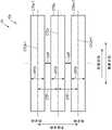
图8是表示通常记录于了中周区域MR的数据的读处理的一个例子的示意图。图8对应于图6。在图8中示出磁道CTRm-1、CTRm以及CTRm+1。磁道CTRm-1、CTRm以及CTRm+1在中周区域MR中按记载的顺序在内方向上连续地被进行通常记录。在中周区域MR中,磁道CTRm在磁道CTRm-1的内方向上与磁道CTRm-1相邻。在中周区域MR中,磁道CTRm+1在磁道CTRm的内方向上与磁道CTRm相邻。在图8中,磁道CTRm-1、CTRm以及CTRm+1的磁道宽度WTW相同。此外,磁道CTRm-1、CTRm以及CTRm+1的磁道宽度也可以不同。在图8中示出磁道CTRm-1的磁道中央CTCm-1、磁道CTRm的磁道中央CTCm以及磁道CTRm+1的磁道中央CTCm+1。例如,磁道中央CTCm相当于基准位置BP。在图8中,磁道CTRm-1、CTRm以及CTRm-1以磁道间距CTP来配置。此外,磁道CTRm-1、CTRm以及CTRm+1也可以以不同的磁道间距来配置。在图8中,读取头15R、例如中间部MP被定位于磁道CTRm的磁道中央CTCm。在将中间部MP定位于了磁道中央CTCm的情况下,读取头15R1和15R2的交叉磁道间隔成为最小值、例如0。在图8中示出在由于设置于服务器架而从空气冷却用的风扇等的外部产生的振动的振动环境下放置的磁盘装置1中定位于了预定的半径位置来进行了读取的情况下的读取头15R、例如中间部MP的轨道(或者轨迹)TJT。在图8中,为了便于说明,将各磁道表示为以预定的磁道宽度在圆周方向上延伸的长方形状,但实际上沿着圆周方向弯曲。另外,各磁道也可以是一边在半径方向上变动、一边在圆周方向上延伸的波状。FIG. 8 is a schematic diagram showing an example of a read process of data normally recorded in the mid-circumference region MR. FIG. 8 corresponds to FIG. 6 . Tracks CTRm-1, CTRm, and CTRm+1 are shown in FIG. 8 . The tracks CTRm-1, CTRm, and CTRm+1 are continuously recorded in the inner direction in the order described in the mid-circumference region MR. In the middle peripheral region MR, the track CTRm is adjacent to the track CTRm-1 in the inner direction of the track CTRm-1. In the middle peripheral region MR, the track CTRm+1 is adjacent to the track CTRm in the inner direction of the track CTRm. In FIG. 8, the track widths WTW of the tracks CTRm-1, CTRm, and CTRm+1 are the same. In addition, the track widths of the tracks CTRm-1, CTRm, and CTRm+1 may be different. 8 shows the track center CTCm-1 of the track CTRm-1, the track center CTCm of the track CTRm, and the track center CTCm+1 of thetrack CTRm+1. For example, the track center CTCm corresponds to the reference position BP. In FIG. 8, tracks CTRm-1, CTRm, and CTRm-1 are arranged with a track pitch CTP. In addition, the tracks CTRm-1, CTRm, and CTRm+1 may be arranged at different track pitches. In FIG. 8 , theread head 15R, eg, the middle portion MP, is positioned at the track center CTCm of the track CTRm. When the intermediate portion MP is positioned at the track center CTCm, the cross-track spacing between the read heads 15R1 and 15R2 becomes the minimum value, eg, 0. FIG. 8 shows a case where themagnetic disk device 1 placed in a vibration environment due to vibration generated from the outside of an air cooling fan or the like installed in a server rack is positioned at a predetermined radial position and read is performed. 15R of the readhead 15R, for example, the track (or track) TJT of the middle part MP. In FIG. 8 , for convenience of description, each track is shown as a rectangular shape extending in the circumferential direction with a predetermined track width, but is actually curved along the circumferential direction. In addition, each track may have a wave shape extending in the circumferential direction while fluctuating in the radial direction.

在图8所示的例子中,读/写控制部610将读取头15R、例如中间部MP定位于磁道中央CTCm来对磁道CTRm进行读取。读/写控制部610在由于来自外部的振动等的影响而读取头15R振动、按照轨道TJT而中间部MP从磁道中央CTCm在半径方向上错开的同时(或者偏移的同时),对磁道CTRm进行读取。读/写控制部610通过交叉磁道间隔为最小值、例如0的读取头15R1和15R2,在读取头15R1和15R2相对于磁道中央CTCm在半径方向上错开的同时对磁道CTRm进行读取。换言之,读/写控制部610在读取头15R1和15R2相互在半径方向上不错开的状态下,读取头15R1和15R2从磁道中央CTCm在半径方向上偏移的同时,对磁道CTRm进行读取。读/写控制部610能够以读取头15R1和15R2不同时错开到相邻磁道CTRm-1和CTRm+1的方式对磁道CTRm进行读取。In the example shown in FIG. 8 , the read/write control unit 610 reads the track CTRm by positioning theread head 15R, eg, the middle portion MP, at the track center CTCm. The read/write control unit 610 vibrates the readhead 15R due to the influence of external vibration or the like, and the intermediate portion MP is shifted (or shifted) in the radial direction from the track center CTCm in accordance with the track TJT. CTRm to read. The read/write control unit 610 reads the track CTRm while the read heads 15R1 and 15R2 are radially shifted relative to the track center CTCm through the read heads 15R1 and 15R2 having the minimum cross-track interval, eg, 0. In other words, the read/write control section 610 reads the track CTRm while the read heads 15R1 and 15R2 are shifted in the radial direction from the track center CTCm in a state where the read heads 15R1 and 15R2 are not spaced apart from each other in the radial direction. Pick. The read/write control unit 610 can read the track CTRm in such a manner that the read heads 15R1 and 15R2 are not simultaneously shifted to the adjacent tracks CTRm-1 and CTRm+1.

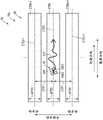
图9是表示瓦记录于了中周区域MR的数据的读处理的一个例子的示意图。图9对应于图7。在图9中示出磁道STRm-1、STRm以及STRm+1。磁道STRm-1、STRm以及STRm+1在中周区域MR中按记载的顺序在顺向上连续地被进行瓦记录。在中周区域MR中,磁道STRm在磁道STRm-1的顺向(内方向)上与磁道STRm-1重叠地被进行写入。在中周区域MR中,磁道STRm+1在磁道STRm的顺向(内方向)上与磁道STRm重叠地被进行写入。在磁道STRm+1未重叠写入其他磁道。磁道STRm+1例如相当于根据一个命令等而被进行了瓦记录的多个磁道中的最后进行了写入的磁道。在图9中,进行磁道STRm的重叠写入之前的磁道STRm-1的磁道宽度WTW、进行磁道STRm+1的重叠写入之前的磁道STRm的磁道宽度WTW以及磁道STRm+1的磁道宽度WTW相同。此外,进行磁道STRm的重叠写入之前的磁道STRm-1的磁道宽度WTW、进行磁道STRm+1的重叠写入之前的磁道STRm的磁道宽度WTW以及磁道STRm+1的磁道宽度WTW也可以不同。在图9中,磁道STRm-1、STRm以及STRm+1以磁道间距STP来配置。此外,磁道STRm-1、STRm以及STRm+1也可以以不同的磁道间距来配置。进行了磁道STRm的重叠写入之后的磁道STRm-1的磁道宽度STW与进行了磁道STRm+1的重叠写入之后的磁道STRm的磁道宽度STW相同。此外,进行了磁道STRm的重叠写入之后的磁道STRm-1的磁道宽度STW与进行了磁道STRm+1的重叠写入之后的磁道STRm的磁道宽度STW也可以不同。在图9中示出进行了磁道STRm的重叠写入之后的磁道STRm-1的磁道宽度STW的半径方向上的中心位置(磁道中央)STCm-1、进行了磁道STRm+1的重叠写入之后的磁道STRm的磁道宽度STW的中心位置(磁道中央)STCm以及磁道STRm+1的磁道宽度WTW的半径方向上的中心位置(磁道中央)STCm+1。例如,磁道中央STCm相当于基准位置BP。在图9中,读取头15R、例如中间部MP被定位于磁道STRm的磁道中央STCm。在将中间部MP定位于了磁道中央STCm的情况下,读取头15R1和15R2的交叉磁道间隔成为最小值、例如0。在图9中示出在振动环境下放置的磁盘装置1中定位于预定的半径位置来进行了读取的情况下的读取头15R、例如中间部MP的轨道TJT。在图9中,为了便于说明,将各磁道表示为以预定的磁道宽度在圆周方向上延伸的长方形状,但实际上沿着圆周方向弯曲。另外,各磁道也可以是一边在半径方向上变动、一边在圆周方向上延伸的波状。此外,在图9中,进行了3个磁道的重叠写入,但也可以进行少于3个或者多于3个的磁道的重叠写入。FIG. 9 is a schematic diagram showing an example of a read process of data recorded on the mid-circumference region MR. FIG. 9 corresponds to FIG. 7 . Tracks STRm-1, STRm, and STRm+1 are shown in FIG. 9 . The tracks STRm-1, STRm, and STRm+1 are sequentially tile-recorded in the forward direction in the order described in the middle circumferential region MR. In the middle peripheral region MR, the track STRm is written to overlap with the track STRm-1 in the forward direction (inward direction) of the track STRm-1. In the middle peripheral region MR, the track STRm+1 is written to overlap the track STRm in the forward direction (inward direction) of the track STRm. The track STRm+1 is not overlapped with other tracks. The track STRm+1 corresponds to, for example, the last written track among a plurality of tracks to which tile recording has been performed in accordance with one command or the like. In FIG. 9 , the track width WTW of the track STRm-1 before the overlapping writing of the track STRm, the track width WTW of the track STRm before the overlapping writing of thetrack STRm+1, and the track width WTW of the track STRm+1 are the same. . Also, the track width WTW of track STRm-1 before overlapping writing of track STRm, the track width WTW of track STRm before overlapping writing oftrack STRm+1, and the track width WTW of track STRm+1 may be different. In FIG. 9, tracks STRm-1, STRm, and STRm+1 are arranged with a track pitch STP. In addition, the tracks STRm-1, STRm, and STRm+1 may be arranged at different track pitches. The track width STW of the track STRm-1 after the overlapping writing of the track STRm is performed is the same as the track width STW of the track STRm after the overlapping writing of thetrack STRm+1. In addition, the track width STW of the track STRm-1 after the overlapping writing of the track STRm and the track width STW of the track STRm after the overlapping writing of the track STRm+1 may be different. FIG. 9 shows the center position (track center) STCm-1 in the radial direction of the track width STW of the track STRm-1 after the overlapping writing of the track STRm and after the overlapping writing of the track STRm+1 has been performed. The center position (track center) STCm of the track width STW of the track STRm and the center position (track center)STCm+1 in the radial direction of the track width WTW of thetrack STRm+1. For example, the track center STCm corresponds to the reference position BP. In FIG. 9, theread head 15R, eg, the middle portion MP, is positioned at the track center STCm of the track STRm. When the intermediate portion MP is positioned at the track center STCm, the cross-track spacing between the read heads 15R1 and 15R2 becomes the minimum value, eg, 0. FIG. 9 shows theread head 15R, for example, the track TJT of the intermediate portion MP, in the case where themagnetic disk device 1 placed in the vibration environment is positioned at a predetermined radial position and read. In FIG. 9 , for convenience of explanation, each track is shown as a rectangular shape extending in the circumferential direction with a predetermined track width, but is actually curved along the circumferential direction. In addition, each track may have a wave shape extending in the circumferential direction while fluctuating in the radial direction. In addition, in FIG. 9, the overlapping writing of three tracks is performed, but the overlapping writing of less than three tracks or more than three tracks may be performed.

在图9所示的例子中,读/写控制部610将读取头15R、例如中间部MP定位于磁道中央STCm来对磁道STRm进行读取。读/写控制部610在由于来自外部的振动等的影响而读取头15R振动、按照轨道TJT而中间部MP相对于磁道中央STCm在半径方向上错开的同时(或者偏移的同时),对磁道STRm进行读取。读/写控制部610通过交叉磁道间隔为最小值、例如0的读取头15R1和15R2,在读取头15R1和15R2相对于磁道中央STCm在半径方向上错开的同时,对磁道STRm进行读取。换言之,读/写控制部610在读取头15R1和15R2相互在半径方向上不错开的状态下,在读取头15R1和15R2相对于磁道中央STCm在半径方向上错开的同时,对磁道STRm进行读取。对于读/写控制部610,读取头15R1和15R2可能同时错开到相邻磁道STRm-1和STRm+1。在读取头15R1和15R2同时错开到了相邻磁道STRm-1和STRm+1的情况下,读/写控制部610有可能无法读取磁道STRm。In the example shown in FIG. 9 , the read/write control unit 610 reads the track STRm by positioning theread head 15R, eg, the middle portion MP, at the track center STCm. The read/write control unit 610, when thepickup 15R vibrates due to the influence of external vibration or the like, and the intermediate portion MP is displaced (or shifted) in the radial direction with respect to the track center STCm according to the track TJT, Track STRm is read. The read/write control unit 610 reads the track STRm while the read heads 15R1 and 15R2 are offset in the radial direction with respect to the track center STCm by using the read heads 15R1 and 15R2 whose cross-track spacing is a minimum value, for example, 0 . In other words, the read/write control section 610 performs the read/write control on the track STRm while the read heads 15R1 and 15R2 are shifted in the radial direction with respect to the track center STCm in a state where the read heads 15R1 and 15R2 are not spaced apart from each other in the radial direction. read. For the read/write control section 610, the read heads 15R1 and 15R2 may be staggered to adjacent tracks STRm-1 and STRm+1 at the same time. When the read heads 15R1 and 15R2 are simultaneously shifted to the adjacent tracks STRm-1 and STRm+1, the read/write control unit 610 may not be able to read the track STRm.

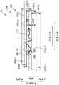
图10是表示通常记录于了外周区域OR的数据的读处理的一个例子的示意图。图10对应于图6。图10的外周区域OR配置于图8和图9的中周区域MR的外方向。在图10中示出磁道CTRo-1、CTRo以及CTRo+1。磁道CTRo-1、CTRo以及CTRo+1在外周区域OR中按记载的顺序在内方向上连续地被进行通常记录。在外周区域OR中,磁道CTRo在磁道CTRo-1的内方向上与磁道CTRo-1相邻。在外周区域OR中,磁道CTRo+1在磁道CTRo的内方向上与磁道CTRo相邻。在图10中,磁道CTRo-1、CTRo以及CTRo+1的磁道宽度WTW相同。此外,磁道CTRo-1、CTRo以及CTRo+1的磁道宽度也可以不同。在图10中示出磁道CTRo-1的磁道中央CTCo-1、磁道CTRo的磁道中央CTCo以及磁道CTRo+1的磁道中央CTCo+1。在图10中,磁道CTRo-1、CTRo以及CTRo-1以磁道间距CTP来配置。此外,磁道CTRo-1、CTRo以及CTRo+1也可以以不同的磁道间距来配置。在图10中,读取头15R、例如中间部MP被定位于磁道CTRo的磁道中央CTCo。在将中间部MP定位于了磁道中央CTCo的情况下,读取头15R1和15R2的交叉磁道间隔成为比最小值大的值。也即是,在将磁道中央CTCo定位于了中间部MP的情况下,读取头15R相对于磁道中央CTCo向外方向倾斜。在图10中示出在振动环境下放置的磁盘装置1中定位于预定的半径位置来进行了读取的情况下的读取头15R、例如中间部MP的轨道TJT。在图10中,为了便于说明,将各磁道表示为以预定的磁道宽度在圆周方向上延伸的长方形状,但实际上沿着圆周方向弯曲。另外,各磁道也可以是一边在半径方向上变动、一边在圆周方向上延伸的波状。FIG. 10 is a schematic diagram showing an example of read processing of data normally recorded in the outer peripheral area OR. FIG. 10 corresponds to FIG. 6 . The outer peripheral region OR of FIG. 10 is arranged in the outer direction of the middle peripheral region MR of FIGS. 8 and 9 . Tracks CTRo-1, CTRo, and CTRo+1 are shown in FIG. 10 . The tracks CTRo-1, CTRo, and CTRo+1 are continuously recorded in the inner direction in the order described in the outer peripheral area OR, and are normally recorded. In the outer peripheral region OR, the track CTRo is adjacent to the track CTRo-1 in the inner direction of the track CTRo-1. In the outer peripheral area OR, the track CTRo+1 is adjacent to the track CTRo in the inner direction of the track CTRo. In FIG. 10, the track widths WTW of the tracks CTRo-1, CTRo and CTRo+1 are the same. In addition, the track widths of the tracks CTRo-1, CTRo, and CTRo+1 may be different. 10 shows the track center CTCo-1 of the track CTRo-1, the track center CTCo of the track CTRo, and the track center CTCo+1 of thetrack CTRo+1. In FIG. 10 , tracks CTRo-1, CTRo, and CTRo-1 are arranged with a track pitch CTP. In addition, the tracks CTRo-1, CTRo, and CTRo+1 may be arranged at different track pitches. In FIG. 10 , theread head 15R, eg, the middle portion MP, is positioned at the track center CTCo of the track CTRo. When the middle portion MP is positioned at the track center CTCo, the cross-track spacing between the heads 15R1 and 15R2 is larger than the minimum value. That is, when the track center CTCo is positioned at the middle portion MP, thepickup 15R is inclined outward with respect to the track center CTCo. 10 shows theread head 15R, for example, the track TJT of the intermediate portion MP, in the case where themagnetic disk device 1 placed in the vibration environment is positioned at a predetermined radial position and read. In FIG. 10 , for convenience of explanation, each track is shown as a rectangular shape extending in the circumferential direction with a predetermined track width, but is actually curved along the circumferential direction. In addition, each track may have a wave shape extending in the circumferential direction while fluctuating in the radial direction.

在图10所示的例子中,读/写控制部610将读取头15R、例如中间部MP定位于磁道中央CTCo来对磁道CTRo进行读取。读/写控制部610在由于来自外部的振动等的影响而读取头15R振动、按照轨道TJT而中间部MP从磁道中央CTCo在半径方向上错开的同时(或者偏移的同时),对磁道CTRo进行读取。读/写控制部610通过交叉磁道间隔为比最小值大的值的读取头15R1和15R2,在读取头15R1和15R2从磁道中央CTCo在半径方向上偏移的同时,对磁道CTRo进行读取。换言之,读/写控制部610在读取头15R相对于磁道中央CTCo向外方向错开、且读取头15R1和15R2相互在半径方向上错开的状态下,在读取头15R1和15R2从磁道中央CTCo在半径方向上偏移的同时,对磁道CTRo进行读取。读/写控制部610能够以读取头15R1和15R2不同时错开到相邻磁道CTRo-1和CTRo+1的方式对磁道CTRo进行读取。In the example shown in FIG. 10 , the read/write control unit 610 reads the track CTRo by positioning theread head 15R, eg, the middle portion MP, at the track center CTCo. The read/write control unit 610 vibrates the readhead 15R due to the influence of external vibration or the like, and at the same time that the middle part MP is shifted (or shifted) in the radial direction from the track center CTCo according to the track TJT, and controls the track. CTRo to read. The read/write control unit 610 reads the track CTRo while the read heads 15R1 and 15R2 are offset in the radial direction from the track center CTCo by crossing the read heads 15R1 and 15R2 whose track spacing is larger than the minimum value. Pick. In other words, the read/write control section 610 in a state in which theread head 15R is displaced outward with respect to the track center CTCo and the read heads 15R1 and 15R2 are displaced from each other in the radial direction, when the read heads 15R1 and 15R2 are displaced from the track center Track CTRo is read while CTCo is shifted in the radial direction. The read/write control unit 610 can read the track CTRo in such a manner that the read heads 15R1 and 15R2 are not simultaneously shifted to the adjacent tracks CTRo-1 and CTRo+1.

图11是表示瓦记录于了外周区域OR的数据的读处理的一个例子的示意图。图11对应于图7。图11的外周区域OR配置于图8和图9的中周区域MR的外方向。在图11中示出磁道STRo-1、STRo以及STRo+1。磁道STRo-1、STRo以及STRo+1在外周区域OR中按记载的顺序在顺向上连续地被进行瓦记录。在外周区域OR中,磁道STRo在磁道STRo-1的顺向(内方向)上与磁道STRo-1重叠地被进行写入。在外周区域OR中,磁道STRo+1在磁道STRo的顺向(内方向)上与磁道STRo重叠地被进行写入。在磁道STRo+1未重叠写入其他磁道。磁道STRo+1例如相当于根据一个命令等而被进行了瓦记录的多个磁道中的最后被进行了写入的磁道。在图11中,进行磁道STRo的重叠写入之前的磁道STRo-1的磁道宽度WTW、进行磁道STRo+1的重叠写入之前的磁道STRo的磁道宽度WTW以及磁道STRo+1的磁道宽度WTW相同。此外,进行磁道STRo的重叠写入之前的磁道STRo-1的磁道宽度WTW、进行磁道STRo+1的重叠写入之前的磁道STRo的磁道宽度WTW以及磁道STRo+1的磁道宽度WTW也可以不同。在图11中,磁道STRo-1、STRo以及STRo+1以磁道间距STP来配置。此外,磁道STRo-1、STRo以及STRo+1也可以以不同的磁道间距来配置。进行了磁道STRo的重叠写入之后的磁道STRo-1的磁道宽度STW与进行了磁道STRo+1的重叠写入之后的磁道STRo的磁道宽度STW相同。此外,进行了磁道STRo的重叠写入之后的磁道STRo-1的磁道宽度STW与进行了磁道STRo+1的重叠写入之后的磁道STRo的磁道宽度STW也可以不同。在图11中示出进行了磁道STRo的重叠写入之后的磁道STRo-1的磁道宽度STW的半径方向上的中心位置(磁道中央)STCo-1、进行了磁道STRo+1的重叠写入之后的磁道STRo的磁道宽度STW的中心位置(磁道中央)STCo以及磁道STRo+1的磁道宽度WTW的半径方向上的中心位置(磁道中央)STCo+1。在图11中,读取头15R、例如中间部MP被定位于磁道STRo的磁道中央STCo。在将中间部MP定位于了磁道中央STCo的情况下,读取头15R1和15R2的交叉磁道间隔成为比最小值大的值。也即是,在将中间部MP定位于了磁道中央STCo的情况下,读取头15R相对于磁道中央STCo而向外方向倾斜。在图11中示出在振动环境下放置的磁盘装置1中定位于预定的半径位置来进行了读取的情况下的读取头15R、例如中间部MP的轨道TJT。在图11中,为了便于说明,将各磁道表示为以预定的磁道宽度在圆周方向上延伸的长方形状,但实际上沿着圆周方向弯曲。另外,各磁道也可以是一边在半径方向上变动、一边在圆周方向上延伸的波状。此外,在图11中,进行了3个磁道的重叠写入,但也可以进行小于3个或者多于3个的磁道的重叠写入。FIG. 11 is a schematic diagram showing an example of read processing of data recorded on the outer peripheral area OR. FIG. 11 corresponds to FIG. 7 . The outer peripheral region OR of FIG. 11 is arranged in the outer direction of the middle peripheral region MR of FIGS. 8 and 9 . Tracks STRo-1, STRo, and STRo+1 are shown in FIG. 11 . Tracks STRo-1, STRo, and STRo+1 are continuously tile-recorded in the forward direction in the order described in the outer peripheral area OR. In the outer peripheral area OR, the track SRo is written to overlap the track SRo-1 in the forward direction (inward direction) of the track SRo-1. In the outer peripheral area OR, the track STRo+1 is written to overlap the track STRo in the forward direction (inner direction) of the track STRo. The track STRo+1 is not overlapped with other tracks. The track STRo+1 corresponds to, for example, the last written track among a plurality of tracks to which tile recording has been performed in accordance with one command or the like. In FIG. 11 , the track width WTW of the track SRo-1 before the overlapping writing of the track SRo, the track width WTW of the track SRo+1 before the overlapping writing of thetrack SRo+1, and the track width WTW of the track SRo+1 are the same. . In addition, the track width WTW of the track SRo-1 before the overlap write of the track SRo, the track width WTW of the track SRo before the overlap write of thetrack SRo+1, and the track width WTW of the track SRo+1 may be different. In FIG. 11, tracks STRo-1, STRo, and STRo+1 are arranged with a track pitch STP. In addition, the tracks STRo-1, STRo, and STRo+1 may be arranged at different track pitches. The track width STW of the track STRo-1 after the overlap writing of the track STRo is performed is the same as the track width STW of the track STRo after the overlap writing of thetrack STRo+1. In addition, the track width STW of the track STRo-1 after the overlapping writing of the track STRo and the track width STW of the track STRo after the overlapping writing of the track STRo+1 may be different. 11 shows the center position (track center) STCo-1 in the radial direction of the track width STW of the track STRo-1 after the overlapping writing of the track STRo and after the overlapping writing of the track STRo+1 is performed. The center position (track center) STCo of the track width STW of the track STRo and the center position (track center)STCo+1 in the radial direction of the track width WTW of thetrack STRo+1. In FIG. 11 , theread head 15R, eg, the middle portion MP, is positioned at the track center STCo of the track STRo. When the intermediate portion MP is positioned at the track center STCo, the cross-track spacing between the read heads 15R1 and 15R2 becomes a value larger than the minimum value. That is, when the intermediate portion MP is positioned at the track center STCo, thepickup 15R is inclined outward with respect to the track center STCo. 11 shows theread head 15R, for example, the track TJT of the intermediate portion MP, in the case where themagnetic disk device 1 placed in a vibration environment is positioned at a predetermined radial position and read. In FIG. 11 , for convenience of description, each track is shown as a rectangular shape extending in the circumferential direction with a predetermined track width, but is actually curved along the circumferential direction. In addition, each track may have a wave shape extending in the circumferential direction while fluctuating in the radial direction. In addition, in FIG. 11, the overlapping writing of three tracks is performed, but the overlapping writing of less than three or more than three tracks may be performed.

在图11所示的例子中,读/写控制部610将读取头15R、例如中间部MP定位于磁道中央STCo来对磁道STRo进行读取。读/写控制部610在由于来自外部的振动等的影响而读取头15R振动、按照轨道TJT而中间部MP相对于磁道中央STCo在半径方向上错开的同时(或者偏移的同时),对磁道STRo进行读取。读/写控制部610通过交叉磁道间隔为比最小值大的值的读取头15R1和15R2,在读取头15R1和15R2从磁道中央STCo在半径方向上偏移的同时,对磁道STRo进行读取。换言之,读/写控制部610在读取头15R相对于磁道中央STCo向外方向错开、且读取头15R1和15R2相互在半径方向上错开的状态下,在读取头15R1和15R2从磁道中央STCo在半径方向上偏移的同时,对磁道STRo进行读取。读/写控制部610能够通过读取头15R1和15R2中的至少一方对磁道STRo进行读取。In the example shown in FIG. 11 , the read/write control unit 610 reads the track STRo by positioning theread head 15R, eg, the middle portion MP, at the track center STCo. The read/write control unit 610, when thepickup 15R vibrates due to the influence of external vibration or the like, and the intermediate portion MP is displaced (or shifted) in the radial direction with respect to the track center STCo according to the track TJT, Track STRo is read. The read/write control section 610 reads the track STRo while the read heads 15R1 and 15R2 are offset in the radial direction from the track center STCo by crossing the read heads 15R1 and 15R2 whose track spacing is larger than the minimum value. Pick. In other words, the read/write control section 610 in a state in which theread head 15R is displaced outward with respect to the track center STCo and the read heads 15R1 and 15R2 are displaced from each other in the radial direction, when the read heads 15R1 and 15R2 are displaced from the track center Track STRo is read while STCo is shifted in the radial direction. The read/write control unit 610 can read the track STRo by at least one of the read heads 15R1 and 15R2.

图12是表示通常记录于内周区域IR的数据的读处理的一个例子的示意图。图12对应于图6。图12的内周区域IR配置在图8和图9的中周区域MR的内方向。在图12中示出磁道CTRi-1、CTRi以及CTRi+1。磁道CTRi-1、CTRi以及CTRi+1在内周区域IR中按记载的顺序在内方向上连续地被进行通常记录。在内周区域IR中,磁道CTRi在磁道CTRi-1的内方向上与磁道CTRi-1相邻。在内周区域IR中,磁道CTRi+1在磁道CTRi的内方向上与磁道CTRi相邻。在图12中,磁道CTRi-1、CTRi以及CTRi+1的磁道宽度WTW相同。此外,磁道CTRi-1、CTRi以及CTRi+1的磁道宽度也可以不同。在图12中示出磁道CTRi-1的磁道中央CTCi-1、磁道CTRi的磁道中央CTCi以及磁道CTRi+1的磁道中央CTCi+1。在图12中,磁道CTRi-1、CTRi以及CTRi-1以磁道间距CTP来配置。此外,磁道CTRi-1、CTRi以及CTRi+1也可以以不同的磁道间距来配置。在图12中,读取头15R、例如中间部MP被定位于磁道CTRi的磁道中央CTCi。在将中间部MP定位于了磁道中央CTCi的情况下,读取头15R1和15R2的交叉磁道间隔成为比最小值大的值。也即是,在将中间部MP定位于了磁道中央CTCi的情况下,读取头15R相对于磁道中央CTCi向外方向倾斜。在图12中示出在振动环境下放置的磁盘装置1中定位于预定的半径位置来进行了读取的情况下的读取头15R、例如中间部MP的轨道TJT。在图12中,为了便于说明,将各磁道表示为以预定的磁道宽度在圆周方向上延伸的长方形状,但实际上沿着圆周方向弯曲。另外,各磁道也可以是一边在半径方向上变动、一边在圆周方向上延伸的波状。FIG. 12 is a schematic diagram showing an example of read processing of data normally recorded in the inner peripheral region IR. FIG. 12 corresponds to FIG. 6 . The inner peripheral region IR of FIG. 12 is arranged in the inner direction of the middle peripheral region MR of FIGS. 8 and 9 . Tracks CTRi-1, CTRi, and CTRi+1 are shown in FIG. 12 . The tracks CTRi-1, CTRi, and CTRi+1 are continuously recorded in the inner direction in the order described in the inner peripheral region IR. In the inner peripheral region IR, the track CTRi is adjacent to the track CTRi-1 in the inner direction of the track CTRi-1. In the inner peripheral region IR, the track CTRi+1 is adjacent to the track CTRi in the inner direction of the track CTRi. In FIG. 12, the track widths WTW of the tracks CTRi-1, CTRi, and CTRi+1 are the same. In addition, the track widths of the tracks CTRi-1, CTRi, and CTRi+1 may be different. 12 shows the track center CTCi-1 of the track CTRi-1, the track center CTCi of the track CTRi, and the track center CTCi+1 of thetrack CTRi+1. In FIG. 12, tracks CTRi-1, CTRi, and CTRi-1 are arranged with a track pitch CTP. In addition, the tracks CTRi-1, CTRi, and CTRi+1 may be arranged at different track pitches. In FIG. 12 , theread head 15R, eg, the middle portion MP, is positioned at the track center CTCi of the track CTRi. When the intermediate portion MP is positioned at the track center CTCi, the cross-track spacing of the read heads 15R1 and 15R2 becomes a value larger than the minimum value. That is, when the intermediate portion MP is positioned at the track center CTCi, thepickup head 15R is inclined outward with respect to the track center CTCi. FIG. 12 shows theread head 15R, for example, the track TJT of the intermediate portion MP, in the case where themagnetic disk device 1 placed in the vibration environment is positioned at a predetermined radial position and read. In FIG. 12 , for convenience of description, each track is shown as a rectangular shape extending in the circumferential direction with a predetermined track width, but is actually curved along the circumferential direction. In addition, each track may have a wave shape extending in the circumferential direction while fluctuating in the radial direction.

在图12所示的例子中,读/写控制部610将读取头15R、例如中间部MP定位于磁道中央CTCi来对磁道CTRi进行读取。读/写控制部610在由于来自外部的振动等的影响而读取头15R振动、按照轨道TJT而中间部MP从磁道中央CTCi在半径方向上错开的同时(或者偏移的同时),对磁道CTRi进行读取。读/写控制部610通过交叉磁道间隔为比最小值大的值的读取头15R1和15R2,在读取头15R1和15R2从磁道中央CTCi在半径方向上偏移的同时,对磁道CTRi进行读取。换言之,读/写控制部610在读取头15R相对于磁道中央CTCi而向内方向上错开、且读取头15R1和15R2相互在半径方向上错开的状态下,在读取头15R1和15R2从磁道中央CTCi在半径方向上偏移的同时,对磁道CTRi进行读取。读/写控制部610能够以读取头15R1和15R2不同时错开到相邻磁道CTRi-1和CTRi+1的方式对磁道CTRi进行读取。In the example shown in FIG. 12 , the read/write control unit 610 reads the track CTRi by positioning theread head 15R, eg, the middle portion MP, at the track center CTCi. The read/write control unit 610 vibrates thepickup head 15R due to the influence of external vibration or the like, and the intermediate portion MP is shifted (or shifted) in the radial direction from the track center CTCi in accordance with the track TJT, and controls the track. CTRi to read. The read/write control section 610 reads the track CTRi while the read heads 15R1 and 15R2 are offset in the radial direction from the track center CTCi by crossing the read heads 15R1 and 15R2 whose track spacing is larger than the minimum value. Pick. In other words, the read/write control section 610 in a state where the readhead 15R is displaced in the inward direction with respect to the track center CTCi and the read heads 15R1 and 15R2 are displaced from each other in the radial direction, the read heads 15R1 and 15R2 are shifted from each other in the inward direction. The track CTRi is read while the track center CTCi is shifted in the radial direction. The read/write control unit 610 can read the track CTRi in such a manner that the read heads 15R1 and 15R2 are not simultaneously shifted to the adjacent tracks CTRi-1 and CTRi+1.

图13是表示瓦记录于内周区域IR的数据的读处理的一个例子的示意图。图13对应于图7。图13的内周区域IR配置在图8和图9的中周区域MR的外方向。在图13中示出磁道STRi-1、STRi以及STRi+1。磁道STRi-1、STRi以及STRi+1在内周区域IR中按记载的顺序在顺向上连续地被进行瓦记录。在内周区域IR中,磁道STRi在磁道STRi-1的顺向(内方向)上与磁道STRi-1重叠地被进行写入。在内周区域IR中,磁道STRi+1在磁道STRi的顺向(内方向)上与磁道STRi重叠地被进行写入。在磁道STRi+1未重叠写入其他磁道。磁道STRi+1例如相当于根据一个命令等而被进行了瓦记录的多个磁道中的最后被进行了写入的磁道。在图13中,进行磁道STRi的重叠写入之前的磁道STRoi-1的磁道宽度WTW、进行磁道STRi+1的重叠写入之前的磁道STRi的磁道宽度WTW以及磁道STRoi+1的磁道宽度WTW相同。此外,进行磁道STRi的重叠写入之前的磁道STRi-1的磁道宽度、进行磁道STRi+1的重叠写入之前的磁道STRi的磁道宽度以及磁道STRi+1的磁道宽度也可以不同。在图13中,磁道STRi-1、STRi以及STRi+1以磁道间距STP来配置。此外,磁道STRi-1、STRi以及STRi+1也可以以不同的磁道间距来配置。进行了磁道STRi的重叠写入之后的磁道STRi-1的磁道宽度STW与进行了磁道STRi+1的重叠写入之后的磁道STRi的磁道宽度STW相同。此外,进行了磁道STRi的重叠写入之后的磁道STRi-1的磁道宽度STW与进行了磁道STRi+1的重叠写入之后的磁道STRi的磁道宽度STW也可以不同。在图13中示出进行了磁道STRo的重叠写入之后的磁道STRi-1的磁道宽度STW的半径方向上的中心位置(磁道中央)STCi-1、进行了磁道STRi+1的重叠写入之后的磁道STRi的磁道宽度STW的中心位置(磁道中央)STCi以及磁道STRi+1的磁道宽度WTW的半径方向上的中心位置(磁道中央)STCi+1。在图13中,读取头15R、例如中间部MP被定位于磁道STRi的磁道中央STCi。在将中间部MP定位于了磁道中央STCi的情况下,读取头15R1和15R2的交叉磁道间隔成为比最小值大的值。也即是,在将中间部MP定位于了磁道中央STCi的情况下,读取头15R相对于磁道中央STCi向内方向倾斜。在图13中示出在振动环境下放置的磁盘装置1中定位于预定的半径位置来进行了读取的情况下的读取头15R、例如中间部MP的轨道TJT。在图13中,为了便于说明,将各磁道表示为以预定的磁道宽度在圆周方向上延伸的长方形状,但实际上沿着圆周方向弯曲。另外,各磁道也可以是一边在半径方向上变动、一边在圆周方向上延伸的波状。此外,在图13中,进行3个磁道的重叠写入,但也可以进行少于3个或者多于3个的磁道进行重叠写入。FIG. 13 is a schematic diagram showing an example of read processing of data recorded on the inner peripheral region IR. FIG. 13 corresponds to FIG. 7 . The inner peripheral region IR of FIG. 13 is arranged in the outer direction of the middle peripheral region MR of FIGS. 8 and 9 . Tracks STRi-1, STRi, and STRi+1 are shown in FIG. 13 . Tracks STRi-1, STRi, and STRi+1 are continuously tile-recorded in the forward direction in the order described in the inner peripheral area IR. In the inner peripheral region IR, the track STRi is written to overlap with the track STRi-1 in the forward direction (inward direction) of the track STRi-1. In the inner peripheral region IR, the track STRi+1 is written to overlap the track STRi in the forward direction (inward direction) of the track STRi. The track STRi+1 is not overlapped with other tracks. The track STRi+1 corresponds to, for example, the last written track among a plurality of tracks to which tile recording has been performed in accordance with one command or the like. In FIG. 13 , the track width WTW of the track STRoi-1 before the overlapping writing of the track STRi, the track width WTW of the track STRi before the overlapping writing of thetrack STRi+1, and the track width WTW of the track STRoi+1 are the same. . In addition, the track width of track STRi-1 before overlapping writing of track STRi, the track width of track STRi before overlapping writing oftrack STRi+1, and the track width of track STRi+1 may be different. In FIG. 13, tracks STRi-1, STRi, and STRi+1 are arranged with a track pitch STP. In addition, the tracks STRi-1, STRi, and STRi+1 may be arranged at different track pitches. The track width STW of the track STRi-1 after the overlapping writing of the track STRi is performed is the same as the track width STW of the track STRi after the overlapping writing of thetrack STRi+1. In addition, the track width STW of the track STRi-1 after the overlapping writing of the track STRi and the track width STW of the track STRi after the overlapping writing of the track STRi+1 may be different. FIG. 13 shows the center position (track center) STCi-1 in the radial direction of the track width STW of the track STRi-1 after the overlapping writing of the track STRo and after the overlapping writing of the track STRi+1 has been performed. The center position (track center) STCi of the track width STW of the track STRi and the radial center position (track center)STCi+1 of the track width WTW of thetrack STRi+1. In FIG. 13 , theread head 15R, eg, the middle portion MP, is positioned at the track center STCi of the track STRi. When the intermediate portion MP is positioned at the track center STCi, the cross-track spacing of the read heads 15R1 and 15R2 becomes a value larger than the minimum value. That is, when the intermediate portion MP is positioned at the track center STCi, thepickup 15R is inclined inward with respect to the track center STCi. 13 shows theread head 15R, for example, the track TJT of the intermediate portion MP, in the case where themagnetic disk device 1 placed in the vibration environment is positioned at a predetermined radial position and read. In FIG. 13 , for convenience of description, each track is shown as a rectangular shape extending in the circumferential direction with a predetermined track width, but is actually curved along the circumferential direction. In addition, each track may have a wave shape extending in the circumferential direction while fluctuating in the radial direction. In addition, in FIG. 13, the overlapping writing of three tracks is performed, but the overlapping writing of less than three tracks or more than three tracks may be performed.

在图13所示的例子中,读/写控制部610将读取头15R、例如中间部MP定位于磁道中央STCi来对磁道STRi进行读取。读/写控制部610在由于来自外部的振动等的影响而读取头15R振动、按照轨道TJT而中间部MP相对于磁道中央STCi在半径方向上错开的同时(或者偏移的同时),对磁道STRi进行读取。读/写控制部610通过交叉磁道间隔为比最小值大的值的读取头15R1和15R2,在读取头15R1和15R2从磁道中央STCi在半径方向上偏移的同时,对磁道STRi进行读取。换言之,读/写控制部610在读取头15R相对于磁道中央STCi向内方向错开、且读取头15R1和15R2相互在半径方向上错开的状态下,读取头15R1和15R2在从磁道中央STCi在半径方向上偏移的同时,对磁道STRi进行读取。读/写控制部610能够通过读取头15R1和15R2中的至少一方对磁道STRi进行读取。In the example shown in FIG. 13 , the read/write control unit 610 reads the track STRi by positioning theread head 15R, eg, the middle portion MP, at the track center STCi. The read/write control unit 610, when the readhead 15R vibrates due to the influence of external vibration or the like, and the intermediate portion MP is displaced (or shifted) in the radial direction with respect to the track center STCi according to the track TJT, The track STRi is read. The read/write control section 610 reads the track STRi while the read heads 15R1 and 15R2 are offset in the radial direction from the track center STCi by crossing the read heads 15R1 and 15R2 whose track spacing is larger than the minimum value. Pick. In other words, the read/write control section 610 in a state where the readhead 15R is displaced inward with respect to the track center STCi and the read heads 15R1 and 15R2 are radially displaced from each other, the read heads 15R1 and 15R2 are displaced from the track center The track STRi is read while the STCi is shifted in the radial direction. The read/write control unit 610 can read the track STRi by at least one of the read heads 15R1 and 15R2.

图14是表示通过交叉磁道间隔为比最小值大的值的两个读取头15R1和15R2读取了预定磁道的情况下的位错误率相对于这些读取头15R1和15R2的偏移量的变化ECL1的一个例子的示意图。在图14中,横轴表示与读取头15R1和15R2(以及中间部MP)从预定磁道的磁道中央在半径方向偏移了的距离(以下有时也称为偏移量或者错开量)对应的DAC值(以下有时也简称为偏移量或者错开量)。在图14的横轴上,偏移量随着向正的箭头的前端侧前进而正的值变大,随着向负的箭头的前端侧前进而负的值变小。在图14的横轴上,偏移量=0dac(原点)相当于预定磁道的磁道中央。纵轴表示错误率、例如位错误率(BER)。在图14的纵轴上,位错误率随着向大的箭头的前端侧前进而变大,随着向负的箭头的前端侧前进而变小。在图14的纵轴示出能够通过读取头15R1和15R2对预定磁道进行读取的阈值TH。例如,在位错误率比阈值TH大的情况下,有可能无法通过读取头15R1和15R2正常地进行读取,在位错误率为阈值TH以下的情况下,能够通过读取头15R1和15R2正常地进行读取。在图14中示出位错误率相对于偏移量的变化(以下有时也简称为位错误率的变化)ECL1。在图14中,位错误率的变化ECL1在偏移量=-85dac时为阈值TH,在偏移量=60dac时为阈值TH。FIG. 14 is a graph showing the shift amount of the bit error rate with respect to the read heads 15R1 and 15R2 when a predetermined track is read by the two read heads 15R1 and 15R2 whose cross-track spacing is larger than the minimum value. Schematic diagram of an example of altered ECL1. In FIG. 14 , the horizontal axis represents the distance corresponding to the radial deviation (hereinafter sometimes referred to as the offset or the offset) of the heads 15R1 and 15R2 (and the intermediate portion MP) from the track center of the predetermined track in the radial direction. DAC value (hereafter, it may also be simply referred to as an offset or a stagger). On the horizontal axis of FIG. 14 , the offset increases toward the distal end side of the positive arrow, and the positive value increases, and the offset amount decreases toward the distal end of the negative arrow. On the horizontal axis of Fig. 14, the offset = 0 dac (origin) corresponds to the track center of the predetermined track. The vertical axis represents an error rate, for example, a bit error rate (BER). On the vertical axis of FIG. 14 , the bit error rate increases toward the leading end of the large arrow, and decreases toward the leading end of the negative arrow. The threshold TH at which predetermined tracks can be read by the read heads 15R1 and 15R2 is shown on the vertical axis of FIG. 14 . For example, when the bit error rate is greater than the threshold value TH, there is a possibility that normal reading cannot be performed by the read heads 15R1 and 15R2, and when the bit error rate is equal to or less than the threshold value TH, the read heads 15R1 and 15R2 may be able to read Read normally. FIG. 14 shows a change in the bit error rate with respect to the offset amount (hereinafter also simply referred to as a change in the bit error rate) ECL1. In FIG. 14, the change ECL1 of the bit error rate is the threshold value TH when the offset amount = -85 dac, and is the threshold value TH when the offset amount = 60 dac.

在图14所示的例子中,如图10~图13所示,读/写控制部610将中间部MP定位于外周区域OR或者内周区域IR的预定磁道的磁道中央,通过交叉磁道间隔为比最小值大的值的两个读取头15R1和15R2对该磁道进行读取。在读取头15R、例如中间部MP在从负的偏移量=-85dac到正的偏移量=60dac的范围(以下有时也称为偏移容限)=145dac中偏移的情况下,读/写控制部610能够正常地对该磁道进行读取。In the example shown in FIG. 14 , as shown in FIGS. 10 to 13 , the read/write control unit 610 positions the middle part MP at the center of the track of the predetermined track in the outer peripheral area OR or the inner peripheral area IR, and the cross-track interval is The track is read by the two read heads 15R1 and 15R2 with a value greater than the minimum value. When the readhead 15R, for example, the intermediate portion MP, is offset in the range from negative offset = -85 dac to positive offset = 60 dac (hereinafter sometimes referred to as offset tolerance) = 145 dac, The read/write control unit 610 can normally read the track.

图15是表示通过交叉磁道间隔为最小值的两个读取头15R1和15R2对预定磁道进行了读取的情况下的位错误率相对于这些读取头15R1和15R2的偏移量的变化ECL2的一个例子的示意图。在图15中,横轴表示读取头15R1和15R2(以及中间部MP)的偏移量。在图15的横轴上,偏移量随着向正的箭头的前端侧前进而正的值变大,随着向负的箭头的前端侧前进而负的值变小。在图15的横轴上,偏移量=0dac(原点)相当于预定磁道的磁道中央。纵轴表示错误率、例如位错误率(BER)。在图15的纵轴上,位错误率随着向大的箭头的前端侧前进而变大,随着向负的箭头的前端侧前进而变小。在图15的纵轴示出阈值TH。在图15中示出位错误率的变化ECL2。在图15中,位错误率的变化ECL2在偏移量=-55dac时为阈值TH,在偏移量=45dac时为阈值TH。FIG. 15 is a graph showing the change ECL2 of the bit error rate with respect to the offset amount of the read heads 15R1 and 15R2 when the predetermined track is read by the two read heads 15R1 and 15R2 with the minimum cross-track spacing. A schematic diagram of an example. In FIG. 15, the horizontal axis represents the offset amount of the read heads 15R1 and 15R2 (and the intermediate portion MP). On the horizontal axis of FIG. 15 , the offset increases toward the distal end side of the positive arrow, and the positive value increases, and the offset amount decreases toward the distal end of the negative arrow. On the horizontal axis of Fig. 15, the offset = 0 dac (origin) corresponds to the track center of the predetermined track. The vertical axis represents an error rate, for example, a bit error rate (BER). On the vertical axis of FIG. 15 , the bit error rate increases toward the leading end of the large arrow and decreases toward the leading end of the negative arrow. The threshold value TH is shown on the vertical axis of FIG. 15 . The change ECL2 of the bit error rate is shown in FIG. 15 . In FIG. 15 , the change ECL2 in the bit error rate is the threshold value TH when the offset amount = −55 dac, and the threshold value TH when the offset amount = 45 dac.

在图15所示的例子中,如图8和图9所示,读/写控制部610将中间部MP定位于中周区域MR的预定磁道的磁道中央,通过交叉磁道间隔为最小值的两个读取头15R1和15R2对该磁道进行读取。在读取头15R、例如中间部MP在从负的偏移量=-55dac到正的偏移量=45dac的偏移容限=100dac中偏移的情况下,读/写控制部610能够正常地对该磁道进行读取。In the example shown in FIG. 15 , as shown in FIGS. 8 and 9 , the read/write control unit 610 positions the middle part MP at the center of the track of the predetermined track in the mid-circumference region MR, and crosses two tracks whose track interval is the minimum value. The tracks are read by the read heads 15R1 and 15R2. In the case where the readhead 15R, for example, the intermediate portion MP, is offset within the offset tolerance=100 dac from the negative offset amount=-55 dac to the positive offset amount= 45 dac, the read/write control unit 610 can operate normally read the track.

图14所示的通过比最小值大的值的交叉磁道间隔的两个读取头15R1和15R2读取预定磁道的情况下的读取头15R1和15R2的偏移容限(=145dac)比图15所示的通过最小值的交叉磁道间隔的两个读取头15R1和15R2读取预定磁道的情况下的读取头15R1和15R2的偏移容限(=100dac)大。因此,通过以瓦记录的方式对能够由交叉磁道间隔为比最小值大的值的两个读取头15R1和15R2进行读取的区域写入数据,以通常记录的方式对能够由交叉磁道间隔为最小值的两个读取头15R1和15R2进行读取的区域写入数据,即使是在因来自外部的振动等的影响而读取头15R进行了振动的情况下,也能够抑制读性能的劣化。Offset tolerance (=145 dac) ratio of the read heads 15R1 and 15R2 in the case where a predetermined track is read by the two read heads 15R1 and 15R2 with a cross-track space greater than the minimum value shown in FIG. 14 The offset tolerance (=100 dac) of the read heads 15R1 and 15R2 in the case where the predetermined track is read by the two read heads 15R1 and 15R2 with the minimum cross-track interval shown at 15 is large. Therefore, by writing data in the watt-recording manner to the area that can be read by the two read heads 15R1 and 15R2 whose cross-track spacing is a value larger than the minimum value, the data that can be read by the cross-track space Even if the readhead 15R vibrates due to the influence of external vibration, etc., the read performance can be suppressed by writing data in the area read by the two read heads 15R1 and 15R2, which are the smallest. deterioration.

图16是表示读取率相对于半径位置的变化的一个例子的示意图。图16对应于图2~图5。在图16中,横轴表示半径位置,纵轴表示能够由多个读取头15R、例如读取头15R1和15R2读取数据的可能性(以下有时也简称为读取率或者读性能)(%)。读取率例如相当于在存在来自外部的振动等的影响的状态下能够由多个读取头15R、例如读取头15R1和15R2正常地进行了读取的数据相对于在没有来自外部的振动等的影响的状态下能够由多个读取头15R、例如读取头15R1和15R2正常地进行了读取的数据的比例。在图16的横轴上,半径位置随着向外方向的箭头的前端侧前进而位于外方向,随着向内方向的箭头的前端侧前进而位于内方向。在图16的横轴上,半径位置被区分为内周区域IR、中周区域MR以及外周区域OR。在图16的纵轴上,读取率随着向大的箭头的前端侧前进而变大,随着向小的箭头的前端侧前进而变小。在图16中示出由多个读取头15R、例如读取头15R1和15R2读取了通常记录于各半径位置的数据的情况下的多个读取头15R、例如读取头15R1和15R2的读取率相对于半径位置的变化(以下有时也简称通常记录数据的读取率的变化)CRPL。在图16中示出由多个读取头15R、例如读取头15R1和15R2读取了瓦记录于各半径位置的数据的情况下的多个读取头15R、例如读取头15R1和15R2的读取率相对于半径位置的变化(以下有时也称为瓦记录数据的读取率的变化)SRPL。FIG. 16 is a schematic diagram showing an example of a change in the read rate with respect to the radial position. FIG. 16 corresponds to FIGS. 2 to 5 . In FIG. 16 , the horizontal axis represents the radial position, and the vertical axis represents the possibility that data can be read by the plurality of read heads 15R, for example, the read heads 15R1 and 15R2 (hereinafter, also simply referred to as read rate or read performance) ( %). The read rate corresponds to, for example, data that can be normally read by the plurality of read heads 15R, for example, the read heads 15R1 and 15R2 under the influence of external vibration or the like, relative to the data that can be read normally without external vibration. The ratio of the data that can be normally read by the plurality of read heads 15R, for example, the read heads 15R1 and 15R2, under the influence of such factors. On the horizontal axis of FIG. 16 , the radial position is located in the outer direction as the front end side of the arrow in the outward direction advances, and is located in the inner direction as the front end side of the arrow in the inward direction advances. On the horizontal axis of FIG. 16 , the radial positions are classified into the inner peripheral region IR, the middle peripheral region MR, and the outer peripheral region OR. On the vertical axis of FIG. 16 , the read rate increases as it goes toward the tip side of the large arrow, and decreases as it goes toward the tip side of the small arrow. 16 shows a plurality of read heads 15R, such as read heads 15R1 and 15R2, in the case where data normally recorded at each radial position is read by a plurality of read heads 15R, such as read heads 15R1 and 15R2 The change in the read rate relative to the radial position (hereinafter sometimes referred to as the change in the read rate of the normal recording data) CRPL. FIG. 16 shows a plurality of read heads 15R, such as read heads 15R1 and 15R2, in the case where the data recorded by the tile at each radial position is read by a plurality of read heads 15R, for example, read heads 15R1 and 15R2 The change in the read rate with respect to the radial position (hereinafter sometimes referred to as the change in the read rate of the tile recorded data) SRPL.

在图16所示的例子中,通常记录数据的读取率的变化CRPL在内周区域IR、中周区域MR以及外周区域OR几乎不变化。瓦记录数据的读取率的变化SRPL在中周区域MR比内周区域IR和外周区域OR小。另外,瓦记录数据的读取率的变化比通常记录数据的读取率的变化CRPL小。In the example shown in FIG. 16 , the change CRPL of the read rate of the normal recording data hardly changes in the inner peripheral area IR, the middle peripheral area MR, and the outer peripheral area OR. The change SRPL of the read rate of the tile recording data is smaller in the middle circumference area MR than in the inner circumference area IR and the outer circumference area OR. In addition, the change in the read rate of the watt-recorded data is smaller than the change CRPL of the read rate of the normal recorded data.

根据图16所示的例子,通过为了进行高磁道密度(Track Per Inch:TPI)化而以瓦记录的方式对盘10的内周区域IR和外周区域OR中的至少一方写入数据,并以通常记录的方式对中周区域MR写入数据,能够不使读性能降低地实现高TPI化。According to the example shown in FIG. 16 , data is written to at least one of the inner peripheral area IR and the outer peripheral area OR of thedisk 10 by tile recording for high track density (Track Per Inch: TPI), and the By writing data to the mid-circumferential region MR by the normal recording method, it is possible to achieve a high TPI without lowering the read performance.

记录区域管理部620按照来自主机100等的指示,对盘10的半径区域进行管理。记录区域管理部620按照来自主机100等的指示,在盘10、例如用户数据区域10a中,对通常记录数据的半径区域(以下有时也称为通常记录区域)和瓦记录数据的半径区域(以下有时也称为瓦记录区域)进行设定或者变更。记录区域管理部620也可以将与对盘10的半径区域、例如用户数据区域10a所设定的通常记录区域和瓦记录区域有关的信息记录于预定的记录区域、例如用户数据区域10a、媒体缓存10b、系统区10c、易失性存储器70或者非易失性存储器80等。The recordingarea management unit 620 manages the radial area of thedisc 10 in accordance with an instruction from thehost computer 100 or the like. In accordance with an instruction from thehost computer 100 or the like, the recordingarea management unit 620 records a radius area (hereinafter sometimes referred to as a normal recording area) and a radius area (hereinafter referred to as a tile) for recording data in thedisc 10, for example, theuser data area 10a. It is sometimes called tile recording area) to set or change. The recordingarea management unit 620 may record information related to the normal recording area and the tile recording area set to the radial area of thedisc 10, such as theuser data area 10a, in a predetermined recording area, such as theuser data area 10a, and the media buffer. 10b,system area 10c,volatile memory 70 ornon-volatile memory 80, etc.

记录区域管理部620按特定大小(或者特定面积)的半径区域或者能够能够通常记录到特定数据容量的半径区域(以下有时也称为通常记录带区域)来对通常记录区域进行管理。通常记录带区域可以包括被进行通常记录的多个磁道。例如,记录区域管理部620在盘10中按通常记录带区域来设定通常记录区域。另外,例如记录区域管理部620按通常记录带区域来将通常记录区域变更为瓦记录区域。此外,记录区域管理部620既可以不按通常记录带区域来设定通常记录区域,也可以按照主机100等的指示来将盘10的任意大小或者面积的半径区域设定为通常记录区域。The recordingarea management unit 620 manages the normal recording area in a radius area of a specific size (or a specific area) or a radius area that can normally record to a specific data capacity (hereinafter sometimes also referred to as a normal recording zone area). The normal recording tape area may include a plurality of tracks on which normal recording is performed. For example, the recordingarea management unit 620 sets the normal recording area on thedisc 10 for each normal recording zone area. In addition, for example, the recordingarea management unit 620 changes the normal recording area to the tile recording area for each normal recording zone area. Note that the recordingarea management unit 620 may not set the normal recording area for the normal recording tape area, or may set a radial area of any size or area of thedisc 10 as the normal recording area in accordance with an instruction from thehost computer 100 or the like.

记录区域管理部620优先地将包含对头15进行了定位时、交叉磁道间隔成为最小值的盘10、例如用户数据区域10a的半径位置(基准位置)BP的半径区域(以下有时也称为最小交叉磁道间隔区域)设定或者变更为通常记录区域。记录区域管理部620优先地将包含对头15、例如中间部MP进行了定位时、读取头15R1和15R2在半径方向上不错开(或者在圆周方向上排列)的用户数据区域10a的半径位置(基准位置)BP的最小交叉磁道间隔区域设定或者变更为通常记录区域。在一个例子中,记录区域管理部620优先地将包含对头15、例如中间部MP进行了定位时、扭斜角成为最小值的用户数据区域10a的半径位置(基准位置)BP的最小交叉磁道间隔区域设定或者变更为通常记录区域。例如,记录区域管理部620优先地对中周区域MR设定通常记录区域。另外,例如,记录区域管理部620优先地将最小交叉磁道间隔区域设定或者变更为通常记录区域,该最小交叉磁道间隔区域是包含对头15进行了定位时、交叉磁道间隔的最小值成为10nm(纳米)以下的盘10、例如用户数据区域10a的半径位置(基准位置)BP的区域。此外,记录区域管理部620也可以将最小交叉磁道间隔区域以外的用户数据区域10a设定为通常记录区域。The recordingarea management unit 620 preferentially selects a radius area (hereinafter sometimes referred to as the minimum crossover) including the radial position (reference position) BP of theuser data area 10a on thedisk 10 at which the cross-track spacing becomes the minimum value when thehead 15 is positioned. track space area) is set or changed to the normal recording area. The recordingarea management unit 620 preferentially includes the radial position ( The minimum cross-track space area of the reference position) BP is set or changed to the normal recording area. In one example, the recordingarea management unit 620 preferentially sets the minimum cross-track interval including the radial position (reference position) BP of theuser data area 10a at which the skew angle becomes the minimum value when thehead 15, for example, the intermediate portion MP is positioned. The area is set or changed to the normal recording area. For example, the recordingarea management unit 620 preferentially sets the normal recording area to the middle circumference area MR. In addition, for example, the recordingarea management unit 620 preferentially sets or changes the minimum cross-track interval area including the minimum cross-track interval when thehead 15 is positioned and the minimum value of the cross-track interval becomes 10 nm ( An area of thedisk 10 smaller than nanometer), for example, the radial position (reference position) BP of theuser data area 10a. In addition, the recordingarea management unit 620 may set theuser data area 10a other than the minimum cross-track space area as the normal recording area.

记录区域管理部620按特定大小(或者特定面积)的半径区域或者能够瓦记录到特定数据容量的半径区域(以下有时也称为瓦记录带区域)对瓦记录区域进行管理。瓦记录带区域可以包括被进行瓦记录的多个磁道。例如,记录区域管理部620在盘10中按瓦记录带区域来设定瓦记录区域。另外,例如记录区域管理部620按瓦记录带区域来将瓦记录区域变更为通常记录区域。此外,记录区域管理部620既可以不按瓦记录带区域来设定通常记录区域,也可以按照主机100等的指示来将盘10的任意大小或者面积的半径区域设定为瓦记录区域。The recordingarea management unit 620 manages the tile recording area in a radius area of a specific size (or a specific area) or a radius area capable of recording a tile to a specific data capacity (hereinafter sometimes referred to as a tile recording zone area). A tiled tape area may include multiple tracks on which tile recording is performed. For example, the recordingarea management unit 620 sets tile recording areas on thedisk 10 for each tile recording zone area. In addition, for example, the recordingarea management unit 620 changes the tile recording area to the normal recording area for each tile recording zone area. Note that the recordingarea management unit 620 may not set a normal recording area for each tile recording zone area, or may set a radial area of any size or area of thedisk 10 as a tile recording area in accordance with an instruction from thehost computer 100 or the like.

记录区域管理部620优先地将包含对头15进行了定位时、交叉磁道间隔成为最大值的盘10、例如用户数据区域10a的半径位置(以下有时也称为最大位置)IRP以及/或者ORP的半径区域(以下有时也称为最大交叉磁道间隔区域)设定或者变更为瓦记录区域。记录区域管理部620优先地将包含对头15、例如中间部MP进行了定位时、读取头15R1和15R2在半径方向上最远离的用户数据区域10a的半径位置(最大位置)IRP以及/或者ORP的最大交叉磁道间隔区域设定或者变更为瓦记录区域。在一个例子中,记录区域管理部620将包括在对头15、例如中间部MP进行了定位时扭斜角成为最大值的用户数据区域10a的半径位置(最大位置)IRP以及/或者ORP的最大交叉磁道间隔区域设定或者变更为瓦记录区域。例如,记录区域管理部620对内周区域IR以及/或者外周区域OR设定瓦记录区域。另外,例如记录区域管理部620优先地将包含对头15进行了定位时、交叉磁道间隔的最大值成为15nm(纳米)以上的盘10、例如用户数据区域10a的半径位置(最大位置)IRP以及/或者ORP的最大交叉磁道间隔区域设定或者变更为瓦记录区域。The recordingarea management unit 620 preferentially includes the radius position (hereinafter sometimes referred to as the maximum position) IRP and/or ORP of thedisc 10 where the cross-track spacing becomes the maximum value when thehead 15 is positioned, for example, theuser data area 10a. The area (hereinafter sometimes referred to as the maximum cross-track space area) is set or changed to the tile recording area. The recordingarea management unit 620 preferentially includes the radial position (maximum position) IRP and/or ORP of theuser data area 10a at which the heads 15R1 and 15R2 are farthest in the radial direction when thehead 15, for example, the intermediate portion MP is positioned. The maximum cross-track spacing area of is set or changed to the tile recording area. In one example, the recordingarea management unit 620 includes the radial position (maximum position) IRP and/or the maximum crossing of the ORP of theuser data area 10a where the skew angle becomes the maximum value when thehead 15, for example, the middle part MP is positioned. The track space area is set or changed to the tile recording area. For example, the recordingarea management unit 620 sets the tile recording area in the inner peripheral area IR and/or the outer peripheral area OR. In addition, for example, the recordingarea management unit 620 preferentially includes the radial position (maximum position) IRP of theuser data area 10a (maximum position) IRP and/ Alternatively, the maximum cross-track space area of the ORP is set or changed to a tile recording area.

例如,最大交叉磁道间隔区域(例如瓦记录区域)中的多个读取头15R中的两个读取头15R的交叉磁道间隔的最大值比最小交叉磁道间隔区域(例如通常记录区域)中的多个读取头15R中的两个读取头15R的交叉磁道间隔的最小值大。换言之,例如最小交叉磁道间隔区域(例如通常记录区域)中的多个读取头15R中的两个读取头15R的交叉磁道间隔的最小值比最大交叉磁道间隔区域(例如瓦记录区域)中的多个读取头15R中的两个读取头15R的交叉磁道间隔的最大值小。此外,记录区域管理部620也可以将最大交叉磁道间隔区域以外的用户数据区域10a设定为瓦记录区域。For example, the maximum value of the cross-track spacing of two of the plurality of read heads 15R in the maximum cross-track spacing area (eg, the tile recording area) is larger than that in the minimum cross-track spacing area (eg, the normal recording area) The minimum value of the cross-track spacing of two readheads 15R among the plurality of read heads 15R is large. In other words, for example, the minimum value of the cross-track spacing of two of the plurality of read heads 15R in the minimum cross-track space area (for example, the normal recording area) is larger than that in the maximum cross-track space area (for example, the tile recording area) The maximum value of the cross-track spacing of two readheads 15R among the plurality of read heads 15R is small. In addition, the recordingarea management unit 620 may set theuser data area 10a other than the maximum cross-track space area as the tile recording area.

图17是表示本实施方式涉及的通常记录区域CR和瓦记录区域SR的配置的一个例子的示意图。FIG. 17 is a schematic diagram showing an example of the arrangement of the normal recording area CR and the tile recording area SR according to the present embodiment.

在图17所示的例子中,记录区域管理部620优先地将包含半径位置MRP(基准位置BP)的最小交叉磁道间隔区域设定为通常记录区域CR,对通常记录区域CR进行数据的通常记录。在图17中,通常记录区域(最小交叉磁道间隔区域)CR由朝向左上的斜线表示。记录区域管理部620优先地将包含半径位置(最大位置)IRP的最大交叉磁道间隔区域设定为瓦记录区域SR,对包含半径位置IRP的瓦记录区域SR进行数据的瓦记录。另外,记录区域管理部620优先地将包含半径位置(最大位置)ORP的最大交叉磁道间隔区域设定为瓦记录区域SR,对包含半径位置ORP的瓦记录区域SR进行数据的瓦记录。在图17中,瓦记录区域(最大交叉磁道间隔区域)SR由朝向右上的斜线表示。此外,记录区域管理部620将通常记录区域CR和瓦记录区域SR之间的用户数据区域10a设定为通常记录区域CR和瓦记录区域SR中的至少一方,对通常记录区域CR进行数据的通常记录,对瓦记录区域SR进行数据的瓦记录。In the example shown in FIG. 17 , the recordingarea management unit 620 preferentially sets the minimum cross-track space area including the radius position MRP (reference position BP) as the normal recording area CR, and performs normal recording of data in the normal recording area CR . In FIG. 17, the normal recording area (minimum cross-track space area) CR is indicated by a diagonal line toward the upper left. The recordingarea management unit 620 preferentially sets the maximum cross-track space area including the radial position (maximum position) IRP as the tile recording area SR, and performs tile recording of data in the tile recording area SR including the radial position IRP. The recordingarea management unit 620 preferentially sets the maximum cross-track space area including the radial position (maximum position) ORP as the tile recording area SR, and performs tile recording of data in the tile recording area SR including the radial position ORP. In FIG. 17, the tile recording area (maximum cross-track space area) SR is indicated by a diagonal line toward the upper right. In addition, the recordingarea management unit 620 sets theuser data area 10a between the normal recording area CR and the tile recording area SR to at least one of the normal recording area CR and the tile recording area SR, and performs normal data recording in the normal recording area CR. For recording, tile recording of data is performed on the tile recording area SR.

图18是表示本实施方式涉及的写处理方法的一个例子的流程图。FIG. 18 is a flowchart showing an example of a write processing method according to the present embodiment.

MPU60判定用户数据区域10a的预定的半径区域是否为最小交叉磁道间隔区域(B1801)。在判定为了预定的半径区域为最小交叉磁道间隔区域的情况下(B1801:是),MPU60优先地将该半径区域设定为通常记录区域CR(B1802),对通常记录区域CR进行数据的通常记录(B1803),结束处理。TheMPU 60 determines whether or not the predetermined radius area of theuser data area 10a is the minimum cross-track space area (B1801). When it is determined that the predetermined radius area is the minimum cross-track space area (B1801: YES), theMPU 60 preferentially sets the radius area as the normal recording area CR (B1802), and performs normal recording of data in the normal recording area CR. (B1803), the process ends.

在判定为了预定的半径区域不是最小交叉磁道间隔区域的情况下(B1801:否),MPU60判定用户数据区域10a的预定的半径区域是否为最大交叉磁道间隔区域(B1804)。在判定为了预定的半径区域是最大交叉磁道间隔区域的情况下(B1804:是),MPU60优先地将该半径区域设定为瓦记录区域SR(B1805),对瓦记录区域SR进行数据的瓦记录(B1806)。When it is determined that the predetermined radius area is not the minimum cross-track space area (B1801: NO), theMPU 60 determines whether the predetermined radius area of theuser data area 10a is the maximum cross-track space area (B1804). When it is determined that the predetermined radius area is the maximum cross-track space area (B1804: YES), theMPU 60 preferentially sets the radius area as the tile recording area SR (B1805), and performs tile recording of data in the tile recording area SR. (B1806).

在判定为了预定的半径区域不是最大交叉磁道间隔区域的情况下(B1804:否),MPU60将用户数据区域10a的预定的半径区域设定为通常记录区域CR以及/或者瓦记录区域SR(B1807),对通常记录区域CR进行数据的通常记录,对瓦记录区域SR进行数据的记录(B1808)。例如,在判定为了预定的半径区域不是最大交叉磁道间隔区域的情况下,MPU60既可以对该半径区域进行数据的通常记录,也可以对该半径区域进行数据的瓦记录。另外,例如在判定为了预定的半径区域不是最大交叉磁道间隔区域的情况下,MPU60也可以对该半径区域的一部分进行数据的通常记录,对该半径区域的一部分以外的区域进行数据的瓦记录。When determining that the predetermined radius area is not the maximum cross-track space area (B1804: NO), theMPU 60 sets the predetermined radius area of theuser data area 10a as the normal recording area CR and/or the tile recording area SR (B1807) , data is normally recorded in the normal recording area CR, and data is recorded in the tile recording area SR (B1808). For example, when it is determined that the predetermined radius area is not the maximum cross-track space area, theMPU 60 may perform normal data recording or tile recording of data for the radius area. Also, for example, when it is determined that the predetermined radius area is not the maximum cross-track space area, theMPU 60 may perform normal data recording in a part of the radius area and tile recording of data in areas other than a part of the radius area.

根据本实施方式,磁盘装置1具有头15,该头15具有写入头15W和多个读取头15R(15R1和15R2)。磁盘装置1优先地将最小交叉磁道间隔区域设定为通常记录区域CR,对最小交叉磁道间隔区域进行数据的通常记录。磁盘装置1优先地将最大交叉磁道间隔区域设定为瓦记录区域SR,对最大交叉磁道间隔区域进行数据的瓦记录。即使是在由于来自外部的振动等的影响而头15相对于预定磁道的磁道中央产生变动的情况下,磁盘装置1也能够通过多个读取头15R中的某一读取头15R正常地读取该磁道。因此,磁盘装置1能够抑制读性能的劣化。According to the present embodiment, themagnetic disk apparatus 1 has thehead 15 having thewrite head 15W and the plurality of read heads 15R ( 15R1 and 15R2 ). Themagnetic disk device 1 preferentially sets the minimum cross-track space area as the normal recording area CR, and performs normal recording of data on the minimum cross-track space area. Themagnetic disk device 1 preferentially sets the maximum cross-track space area as the tile recording area SR, and performs tile recording of data on the maximum cross-track space area. Even if thehead 15 fluctuates with respect to the track center of a predetermined track due to the influence of external vibration or the like, themagnetic disk device 1 can read normally by one of the plurality of read heads 15R. take the track. Therefore, themagnetic disk apparatus 1 can suppress the deterioration of the read performance.

接着,对变形例涉及的磁盘装置进行说明。在变形例中,对与前述的实施方式相同的部分赋予同一参照标号,省略其详细的说明。Next, a magnetic disk device according to a modified example will be described. In the modified example, the same reference numerals are assigned to the same parts as those of the above-mentioned embodiment, and the detailed description thereof is omitted.

(变形例1)(Variation 1)

变形例1涉及的磁盘装置1的头15的结构与前述的实施方式涉及的磁盘装置1不同。The configuration of thehead 15 of themagnetic disk device 1 according toModification 1 is different from that of themagnetic disk device 1 according to the aforementioned embodiment.

读取头15R具有多个读取头、例如3个读取头15R1、15R2以及15R3。读取头15R1例如设置在距写入头15W最远的位置。读取头15R2例如设置在距写入头15W比读取头15R1距写入头15W近的位置。读取头15R3例如设置在距写入头15W比读取头15R2距写入头15W近的位置。读取头15R2位于读取头15R1与读取头15R3之间,读取头15R3位于写入头15W与读取头15R2之间。此外,读取头15R也可以具有4个以上的读取头。以下,既有时将多个读取头、例如3个读取头15R1、15R2以及15R3一并称为读取头15R,也有时将多个读取头、例如读取头15R1、15R2以及15R3中的某一个简称为读取头15R。The readhead 15R has a plurality of read heads, for example, three read heads 15R1, 15R2, and 15R3. The read head 15R1 is provided, for example, at the farthest position from thewrite head 15W. The read head 15R2 is provided, for example, at a position closer to thewrite head 15W than the read head 15R1 is to thewrite head 15W. The read head 15R3 is provided, for example, at a position closer to thewrite head 15W than the read head 15R2 is to thewrite head 15W. The read head 15R2 is located between the read head 15R1 and the read head 15R3, and the read head 15R3 is located between thewrite head 15W and the read head 15R2. In addition, theread head 15R may have four or more read heads. Hereinafter, a plurality of read heads, for example, three read heads 15R1, 15R2, and 15R3 may be collectively referred to as readhead 15R, and a plurality of read heads, such as read heads 15R1, 15R2, and 15R3, may be collectively referred to as One of them is simply referred to as theread head 15R.

图19是表示将读取头15R2定位于了半径位置MRP的情况下的写入头15W和3个读取头15R1、15R2、15R3的几何配置的一个例子的示意图。在图19中示出写入头15W的中心部WC、读取头15R1的中心部RC1、读取头15R2的中心部RC2以及读取头15R3的中心部RC3。在图19所示的例子中,将读取头15R2配置或者定位于对象位置来进行数据的写/读。此外,也可以将多个读取头15R中的读取头15R2以外的读取头15R配置或者定位于对象位置来进行数据的写/读。另外,也可以将多个读取头15R中的两个读取头15R之间的中间部配置或者定位于对象位置来进行数据的写/读。19 is a schematic diagram showing an example of the geometric arrangement of thewrite head 15W and the three read heads 15R1 , 15R2 , and 15R3 when the read head 15R2 is positioned at the radial position MRP. 19 shows the center portion WC of thewrite head 15W, the center portion RC1 of the read head 15R1, the center portion RC2 of the read head 15R2, and the center portion RC3 of the read head 15R3. In the example shown in FIG. 19, the read head 15R2 is arranged or positioned at the target position, and data writing/reading is performed. In addition, theread head 15R other than the read head 15R2 among the plurality of read heads 15R may be arranged or positioned at the target position to perform writing/reading of data. In addition, writing/reading of data may be performed by arranging or positioning an intermediate portion between two readingheads 15R among the plurality of reading heads 15R at a target position.

在图19所示的例子中,在将读取头15R2配置于了半径位置MRP(基准位置BP)的情况下,写入头15W、读取头15R2以及读取头15R3沿着圆周方向排列。写入头15W、读取头15R2以及读取头15R3与读取头15R1不沿着圆周方向排列。在将读取头15R2配置于了半径位置MRP(基准位置BP)的情况下,读取头15R2和15R3之间的循着磁道间隔(DTS)为距离DSm1。也即是,读取头15R2和15R3之间的循着磁道间隔与读取头15R1和15R2之间的循着磁道间隔相同。In the example shown in FIG. 19, when the read head 15R2 is arranged at the radial position MRP (reference position BP), thewrite head 15W, the read head 15R2, and the read head 15R3 are arranged in the circumferential direction. Thewrite head 15W, the read head 15R2, and the read head 15R3 and the read head 15R1 are not arranged in the circumferential direction. When the read head 15R2 is arranged at the radial position MRP (reference position BP), the tracking space (DTS) between the read heads 15R2 and 15R3 is the distance DSm1. That is, the tracking interval between the read heads 15R2 and 15R3 is the same as the tracking interval between the read heads 15R1 and 15R2.

在图19所示的例子中,在将读取头15R2配置于了半径位置MRP(基准位置BP)的情况下,写入头15W、读取头15R2以及读取头15R3不在半径方向上错开。换言之,写入头15W、读取头15R2以及读取头15R3位于半径位置MRP(基准位置BP)。此外,在将读取头15R2配置于了半径位置MRP(基准位置BP)的情况下,写入头15W、读取头15R2以及读取头15R3也可以在半径方向上错开。在将读取头15R2配置于了半径位置MRP(基准位置BP)的情况下,写入头15W、读取头15R2以及读取头15R3与读取头15R1在半径方向上错开。此外,在将读取头15R2配置于了半径位置MRP(基准位置BP)的情况下,写入头15W、读取头15R2以及读取头15R3与读取头15R1也可以在半径方向上不错开。在图19中,头15的扭斜角θsw为0°。在将读取头15R2配置于了半径位置MRP(基准位置BP)的情况下,读取头15R1和15R2之间的交叉磁道间隔(CTS)为距离CSm1。在将读取头15R2配置于了半径位置MRP(基准位置BP)的情况下,读取头15R2和15R3之间的交叉磁道间隔(CTS)为最小值、例如距离CSm0=0。读取头15R1和15R3之间的交叉磁道间隔(CTS)为距离CSm1。此外,在将读取头15R2配置于了半径位置MRP(基准位置BP)的情况下,写入头15W、读取头15R1、读取头15R2以及读取头15R3也可以分别在半径方向上错开。In the example shown in FIG. 19 , when the read head 15R2 is arranged at the radial position MRP (reference position BP), thewrite head 15W, the read head 15R2 and the read head 15R3 are not shifted in the radial direction. In other words, thewrite head 15W, the read head 15R2, and the read head 15R3 are located at the radial position MRP (reference position BP). In addition, when the read head 15R2 is arranged at the radial position MRP (reference position BP), thewrite head 15W, the read head 15R2 and the read head 15R3 may be shifted in the radial direction. When the read head 15R2 is arranged at the radial position MRP (reference position BP), thewrite head 15W, the read head 15R2, and the read head 15R3 are offset from the read head 15R1 in the radial direction. In addition, when the read head 15R2 is arranged at the radial position MRP (reference position BP), thewrite head 15W, the read head 15R2, the read head 15R3 and the read head 15R1 may not be spaced apart in the radial direction. . In FIG. 19 , the skew angle θsw of thehead 15 is 0°. When the read head 15R2 is arranged at the radial position MRP (reference position BP), the cross-track spacing (CTS) between the read heads 15R1 and 15R2 is the distance CSm1. When the read head 15R2 is arranged at the radial position MRP (reference position BP), the cross-track spacing (CTS) between the read heads 15R2 and 15R3 is the minimum value, for example, the distance CSm0=0. The cross track spacing (CTS) between the read heads 15R1 and 15R3 is the distance CSm1. In addition, when the read head 15R2 is arranged at the radial position MRP (reference position BP), thewrite head 15W, the read head 15R1, the read head 15R2, and the read head 15R3 may be shifted in the radial direction, respectively. .

图20是表示将读取头15R2定位于了半径位置IRP的情况下的写入头15W和3个读取头15R1、15R2、15R3的几何配置的一个例子的示意图。20 is a schematic diagram showing an example of the geometric arrangement of thewrite head 15W and the three read heads 15R1 , 15R2 , and 15R3 when the read head 15R2 is positioned at the radial position IRP.

在图20所示的例子中,在将读取头15R2配置于了半径位置IRP的情况下,写入头15W、读取头15R1、读取头15R2以及读取头15R3相对于沿着圆周方向延长的轴以扭斜角θsw=θswi1向内方向倾斜。In the example shown in FIG. 20, when the read head 15R2 is arranged at the radial position IRP, thewrite head 15W, the read head 15R1, the read head 15R2, and the read head 15R3 are relative to the circumferential direction. The elongated shaft is inclined inward at a skew angle θsw=θswi1.

在图20所示的例子中,在将读取头15R2配置于了半径位置IRP的情况下,写入头15W、读取头15R1、读取头15R2以及读取头15R3分别在半径方向上错开。此外,在将读取头15R2配置于了半径位置IRP的情况下,写入头15W、读取头15R1、读取头15R2以及读取头15R3也可以分别在半径方向上不错开。在将读取头15R2配置于了半径位置IRP的情况下,读取头15R1和15R2之间的交叉磁道间隔为距离CSi2。在将读取头15R2配置于了半径位置IRP的情况下,读取头15R2和15R3之间的交叉磁道间隔为距离CSi1。读取头15R1和15R3之间的交叉磁道间隔为距离CSi3。例如,交叉磁道间隔CSi2比交叉磁道间隔CSi1大。例如,交叉磁道间隔CSi3比交叉磁道间隔CSi2大。在一个例子中,交叉磁道间隔CSi3是将头15、例如读取头15R2定位于用户数据区域10a内的情况下的读取头15R1、15R2以及15R3中的两个读取头15R之间的交叉磁道间隔的最大值。此外,交叉磁道间隔CSi3也可以不是将头15、例如读取头15R2定位于用户数据区域10a内的情况下的读取头15R1、15R2以及15R3中的两个读取头15R之间的交叉磁道间隔的最大值。In the example shown in FIG. 20, when the read head 15R2 is arranged at the radial position IRP, thewrite head 15W, the read head 15R1, the read head 15R2, and the read head 15R3 are shifted in the radial direction, respectively. . In addition, when the read head 15R2 is arranged at the radial position IRP, thewrite head 15W, the read head 15R1, the read head 15R2, and the read head 15R3 may not be spaced apart in the radial direction, respectively. When the read head 15R2 is arranged at the radial position IRP, the cross-track interval between the read heads 15R1 and 15R2 is the distance CSi2. When the read head 15R2 is arranged at the radial position IRP, the cross-track interval between the read heads 15R2 and 15R3 is the distance CSi1. The cross-track spacing between read heads 15R1 and 15R3 is distance CSi3. For example, the cross-track spacing CSi2 is larger than the cross-track spacing CSi1. For example, the cross-track spacing CSi3 is larger than the cross-track spacing CSi2. In one example, the cross-track spacing CSi3 is the intersection between two of the read heads 15R1, 15R2, and 15R3 if thehead 15, eg, the read head 15R2, is positioned within theuser data area 10a Maximum track spacing. In addition, the cross-track spacing CSi3 may not be a cross-track between two of the read heads 15R1, 15R2, and 15R3 when thehead 15, for example, the read head 15R2, is positioned within theuser data area 10a. The maximum value of the interval.

图21是表示将读取头15R2定位于了半径位置ORP的情况下的写入头15W和3个读取头15R1、15R2、15R3的几何配置的一个例子的示意图。21 is a schematic diagram showing an example of the geometric arrangement of thewrite head 15W and the three read heads 15R1 , 15R2 , and 15R3 when the read head 15R2 is positioned at the radial position ORP.

在图21所示的例子中,在将读取头15R2配置于了半径位置ORP的情况下,写入头15W、读取头15R1、读取头15R2以及读取头15R3相对于沿着圆周方向延长的轴以扭斜角θsw=θswo1向外方向倾斜。例如,扭斜角θswo1与扭斜角θswi1相同。此外,扭斜角θswo1也可以与扭斜角θswi不同。扭斜角θswo1例如也可以比扭斜角θswi大。扭斜角θswo1例如也可以比扭斜角θswi小。In the example shown in FIG. 21, when the read head 15R2 is arranged at the radial position ORP, thewrite head 15W, the read head 15R1, the read head 15R2, and the read head 15R3 are relative to the circumferential direction. The elongated shaft is inclined in the outward direction at a skew angle θsw=θswo1. For example, the skew angle θswo1 is the same as the skew angle θswi1. Also, the skew angle θswo1 may be different from the skew angle θswi. The skew angle θswo1 may be larger than the skew angle θswi, for example. The skew angle θswo1 may be smaller than the skew angle θswi, for example.

在图21所示的例子中,在将读取头15R2配置于了半径位置ORP的情况下,写入头15W、读取头15R1、读取头15R2以及读取头15R3分别在半径方向上错开。此外,在将读取头15R2配置于了半径位置ORP的情况下,写入头15W、读取头15R1、读取头15R2以及读取头15R3也可以分别在半径方向上不错开。在将读取头15R2配置于了半径位置ORP的情况下,读取头15R1和15R2之间的交叉磁道间隔为距离CSo0=0。在将读取头15R2配置于了半径位置ORP的情况下,读取头15R2和15R3之间的交叉磁道间隔为距离CSo1。在将读取头15R2配置于了半径位置ORP的情况下,读取头15R1和15R3之间的交叉磁道间隔为距离CSo1。例如,交叉磁道间隔CSo1比交叉磁道间隔CSo0(=0)大。In the example shown in FIG. 21, when the read head 15R2 is arranged at the radial position ORP, thewrite head 15W, the read head 15R1, the read head 15R2, and the read head 15R3 are shifted in the radial direction, respectively. . In addition, when the read head 15R2 is arranged at the radial position ORP, thewrite head 15W, the read head 15R1, the read head 15R2, and the read head 15R3 may not be spaced apart in the radial direction, respectively. When the read head 15R2 is arranged at the radial position ORP, the cross-track interval between the read heads 15R1 and 15R2 is the distance CSo0=0. When the read head 15R2 is arranged at the radial position ORP, the cross-track interval between the read heads 15R2 and 15R3 is the distance CSo1. When the read head 15R2 is arranged at the radial position ORP, the cross-track interval between the read heads 15R1 and 15R3 is the distance CSo1. For example, the cross-track space CSo1 is larger than the cross-track space CSo0 (=0).

根据变形例1,磁盘装置1具有头15,该头15具有写入头15W和多个读取头15R(15R1、15R2以及15R3)。磁盘装置1优先地将最小交叉磁道间隔区域设定为通常记录区域CR,对最小交叉磁道间隔区域进行数据的通常记录。磁盘装置1优先地将最大交叉磁道间隔区域设定为瓦记录区域SR,对最大交叉磁道间隔区域进行数据的瓦记录。即使是在因来自外部的振动等的影响而头15相对于预定磁道的磁道中央发生变动的情况下,磁盘装置1也能够通过多个读取头15R中的某一读取头15R正常地读取该磁道。因此,磁盘装置1能够抑制读性能的劣化。According toModification 1, themagnetic disk device 1 includes thehead 15 including thewrite head 15W and the plurality of read heads 15R ( 15R1 , 15R2 , and 15R3 ). Themagnetic disk device 1 preferentially sets the minimum cross-track space area as the normal recording area CR, and performs normal recording of data on the minimum cross-track space area. Themagnetic disk device 1 preferentially sets the maximum cross-track space area as the tile recording area SR, and performs tile recording of data on the maximum cross-track space area. Even when the track center of thehead 15 relative to a predetermined track fluctuates due to the influence of external vibration or the like, themagnetic disk device 1 can read normally by any of the plurality of read heads 15R. take the track. Therefore, themagnetic disk apparatus 1 can suppress the deterioration of the read performance.

(变形例2)(Variation 2)

变形例2涉及的磁盘装置1的头15的结构与前述的实施方式涉及的磁盘装置1不同。The configuration of thehead 15 of themagnetic disk device 1 according to Modification 2 is different from that of themagnetic disk device 1 according to the aforementioned embodiment.

图22是表示变形例2涉及的头15相对于盘10的配置的一个例子的示意图。FIG. 22 is a schematic diagram showing an example of the arrangement of thehead 15 with respect to thedisk 10 according to Modification 2. As shown in FIG.

在图22所示的例子中,用户数据区域10a被区分为位于内方向的内周区域IR、位于外方向的外周区域OR以及位于内周区域IR与外周区域OR之间的中周区域MR。在图22中,用户数据区域10a包括半径位置IRP、半径位置MRP、半径位置MORP以及半径位置ORP。半径位置MORP位于半径位置MRP和半径位置ORP之间。在图22中,半径位置MORP位于外周区域OR。此外,半径位置MORP也可以位于中周区域MR。In the example shown in FIG. 22, theuser data area 10a is divided into an inner peripheral area IR located in the inner direction, an outer peripheral area OR located in the outer direction, and a middle peripheral area MR located between the inner peripheral area IR and the outer peripheral area OR. In FIG. 22, theuser data area 10a includes a radial position IRP, a radial position MRP, a radial position MORP, and a radial position ORP. The radial position MORP is located between the radial position MRP and the radial position ORP. In FIG. 22, the radial position MORP is located in the outer peripheral region OR. In addition, the radial position MORP may be located in the mid-circumference region MR.

图23是表示变形例2涉及的将中间部MP定位于了半径位置MRP的情况下的写入头15W和两个读取头15R1、15R2的几何配置的一个例子的示意图。在图23中示出写入头15W的中心部WC、读取头15R1的中心部RC1以及读取头15R2的中心部RC2。在图23所示的例子中,将中间部MP配置或者定位于对象位置来进行数据的写/读。23 is a schematic diagram showing an example of the geometrical arrangement of thewrite head 15W and the two read heads 15R1 and 15R2 when the intermediate portion MP is positioned at the radial position MRP according to the second modification. 23 shows the center portion WC of thewrite head 15W, the center portion RC1 of the read head 15R1, and the center portion RC2 of the read head 15R2. In the example shown in FIG. 23, data writing/reading is performed by arranging or positioning the intermediate part MP at the target position.

在图23所示的例子中,在将中间部MP配置于了半径位置MRP的情况下,写入头15W和读取头15R2沿着圆周方向排列。写入头15W以及读取头15R2与读取头15R1不沿着圆周方向排列。在将中间部MP配置于了半径位置MRP的情况下,读取头15R1和15R2之间的循着磁道间隔(DTS)为距离DSm1。In the example shown in FIG. 23 , when the intermediate portion MP is arranged at the radial position MRP, thewrite head 15W and the read head 15R2 are arranged in the circumferential direction. Thewrite head 15W and the read head 15R2 and the read head 15R1 are not arranged in the circumferential direction. When the intermediate portion MP is arranged at the radial position MRP, the tracking space (DTS) between the read heads 15R1 and 15R2 is the distance DSm1.

在图23所示的例子中,在将中间部MP配置于了半径位置MRP的情况下,写入头15W和读取头15R2在半径方向上不错开。换言之,写入头15W和读取头15R2位于半径位置MRP。此外,在将中间部MP配置于了半径位置MRP的情况下,写入头15W和读取头15R2也可以在半径方向上错开。在将中间部MP配置于了半径位置MRP的情况下,写入头15W以及读取头15R2与读取头15R1在半径方向上错开。此外,在将中间部MP配置于了半径位置MRP的情况下,写入头15W以及读取头15R2与读取头15R1也可以在半径方向上不错开。在图23中,头15的扭斜角θsw为0°。在将中间部MP配置于了半径位置MRP的情况下,读取头15R1和15R2之间的交叉磁道间隔(CTS)为距离CSm1。此外,在将中间部MP配置于了半径位置MRP的情况下,写入头15W、读取头15R1以及读取头15R2也可以分别在半径方向上错开。In the example shown in FIG. 23 , when the intermediate portion MP is arranged at the radial position MRP, thewrite head 15W and the read head 15R2 are not spaced apart in the radial direction. In other words, thewrite head 15W and the read head 15R2 are located at the radial position MRP. In addition, when the intermediate portion MP is arranged at the radial position MRP, thewrite head 15W and the read head 15R2 may be shifted in the radial direction. When the intermediate portion MP is arranged at the radial position MRP, thewrite head 15W, the read head 15R2 and the read head 15R1 are shifted in the radial direction. Further, when the intermediate portion MP is arranged at the radial position MRP, thewrite head 15W, the read head 15R2 and the read head 15R1 may not be spaced apart in the radial direction. In FIG. 23 , the skew angle θsw of thehead 15 is 0°. When the intermediate portion MP is arranged at the radial position MRP, the cross-track spacing (CTS) between the read heads 15R1 and 15R2 is the distance CSm1. In addition, when the intermediate portion MP is arranged at the radial position MRP, thewrite head 15W, the read head 15R1 and the read head 15R2 may be shifted in the radial direction, respectively.

图24是表示变形例2涉及的将中间部MP定位于了半径位置IRP的情况下的写入头15W和两个读取头15R1、15R2的几何配置的一个例子的示意图。24 is a schematic diagram showing an example of the geometrical arrangement of thewrite head 15W and the two read heads 15R1 and 15R2 when the intermediate portion MP is positioned at the radial position IRP according to the second modification.

在图24所示的例子中,在将中间部MP配置于了半径位置IRP的情况下,写入头15W、读取头15R1以及读取头15R2相对于沿着圆周方向延长的轴以扭斜角θsw=θswi1向内方向倾斜。In the example shown in FIG. 24, when the intermediate portion MP is arranged at the radial position IRP, thewrite head 15W, the read head 15R1, and the read head 15R2 are skewed with respect to the axis extending in the circumferential direction. The angle θsw=θswi1 is inclined inward.

在图24所示的例子中,在将中间部MP配置于了半径位置IRP的情况下,写入头15W、读取头15R1以及读取头15R2分别在半径方向上错开。此外,在将中间部MP配置于了半径位置IRP的情况下,写入头15W、读取头15R1以及读取头15R2也可以分别在半径方向上不错开。在将中间部MP配置于了半径位置IRP的情况下,读取头15R1和15R2之间的交叉磁道间隔为距离CSi2。例如,交叉磁道间隔CSi2比交叉磁道间隔CSm1大。交叉磁道间隔CSi2是将头15、例如中间部MP定位于用户数据区域10a内的情况下的读取头15R1和15R2之间的交叉磁道间隔的最大值。此外,交叉磁道间隔CSi2也可以不是将头15、例如中间部MP定位于用户数据区域10a内的情况下的读取头15R1和15R2之间的交叉磁道间隔的最大值。In the example shown in FIG. 24 , when the intermediate portion MP is arranged at the radial position IRP, thewrite head 15W, the read head 15R1 , and the read head 15R2 are shifted in the radial direction, respectively. Further, when the intermediate portion MP is arranged at the radial position IRP, thewrite head 15W, the read head 15R1 and the read head 15R2 may not be spaced apart in the radial direction, respectively. When the intermediate portion MP is arranged at the radial position IRP, the cross-track interval between the read heads 15R1 and 15R2 is the distance CSi2. For example, the cross-track interval CSi2 is larger than the cross-track interval CSm1. The cross-track interval CSi2 is the maximum value of the cross-track interval between the read heads 15R1 and 15R2 when thehead 15, eg, the middle portion MP, is positioned within theuser data area 10a. In addition, the cross-track interval CSi2 may not be the maximum value of the cross-track interval between the read heads 15R1 and 15R2 when thehead 15, eg, the middle portion MP, is positioned within theuser data area 10a.

图25是变形例2涉及的将中间部MP定位于了半径位置MORP的情况下的写入头15W和两个读取头15R1、15R2的几何配置的一个例子的示意图。25 is a schematic diagram showing an example of the geometric arrangement of thewrite head 15W and the two read heads 15R1 and 15R2 when the intermediate portion MP is positioned at the radial position MORP according to the second modification.

在图25所示的例子中,在将中间部MP配置于了半径位置MORP的情况下,写入头15W、读取头15R1以及读取头15R2相对于沿着圆周方向延长的轴以扭斜角θsw=θswo2向外方向倾斜。例如,扭斜角θswo2的绝对值比扭斜角θswi1的绝对值小。此外,扭斜角θswo2的绝对值也可以与扭斜角θswi1的绝对值不同。扭斜角θswo2的绝对值例如也可以比扭斜角θswi1的绝对值大。扭斜角θswo2例如也可以与扭斜角θswi1相同。In the example shown in FIG. 25 , when the intermediate portion MP is arranged at the radial position MORP, thewrite head 15W, the read head 15R1 and the read head 15R2 are skewed with respect to the axis extending in the circumferential direction. The angle θsw=θswo2 is inclined in the outward direction. For example, the absolute value of the skew angle θswo2 is smaller than the absolute value of the skew angle θswi1. In addition, the absolute value of the skew angle θswo2 may be different from the absolute value of the skew angle θswi1. The absolute value of the skew angle θswo2 may be larger than the absolute value of the skew angle θswi1, for example. The skew angle θswo2 may be the same as the skew angle θswi1, for example.

在图25所示的例子中,在将中间部MP配置于了半径位置MORP的情况下,写入头15W、读取头15R1以及读取头15R2分别在半径方向上错开。此外,在将中间部MP配置于了半径位置MORP的情况下,写入头15W、读取头15R1以及读取头15R2也可以分别在半径方向上不错开。在将中间部MP配置于了半径位置MORP的情况下,读取头15R1和15R2之间的交叉磁道间隔为距离CSmo0=0。也即是,在将中间部MP配置于了半径位置MORP的情况下,读取头15R1和15R2在半径方向上不错开。换言之,在将中间部MP配置于了半径位置MORP的情况下,读取头15R1和15R2位于相同的半径位置。在图25所示的例子中,半径位置MORP相当于基准位置BP。In the example shown in FIG. 25 , when the intermediate portion MP is arranged at the radial position MORP, thewrite head 15W, the read head 15R1 , and the read head 15R2 are shifted in the radial direction, respectively. Further, when the intermediate portion MP is arranged at the radial position MORP, thewrite head 15W, the read head 15R1 and the read head 15R2 may not be spaced apart in the radial direction, respectively. When the intermediate portion MP is arranged at the radial position MORP, the cross-track interval between the read heads 15R1 and 15R2 is the distance CSmo0=0. That is, when the intermediate portion MP is arranged at the radial position MORP, the read heads 15R1 and 15R2 do not move apart in the radial direction. In other words, when the intermediate portion MP is arranged at the radial position MORP, the read heads 15R1 and 15R2 are located at the same radial position. In the example shown in FIG. 25, the radial position MORP corresponds to the reference position BP.

图26是表示变形例2涉及的将中间部MP定位于了半径位置ORP的情况下的写入头15W和两个读取头15R1、15R2的几何配置的一个例子的示意图。26 is a schematic diagram showing an example of the geometrical arrangement of thewrite head 15W and the two read heads 15R1 and 15R2 when the intermediate portion MP is positioned at the radial position ORP according to the second modification.

在图26所示的例子中,在将中间部MP配置于了半径位置ORP的情况下,写入头15W、读取头15R1以及读取头15R2相对于沿着圆周方向延长的轴以扭斜角θsw=θswo1向外方向倾斜。例如,扭斜角θswo1与扭斜角θswi1相同。此外,扭斜角θswo1也可以与扭斜角θswi不同。扭斜角θswo1例如也可以比扭斜角θswi大。扭斜角θswo1例如也可以比扭斜角θswi小。In the example shown in FIG. 26 , when the intermediate portion MP is arranged at the radial position ORP, thewrite head 15W, the read head 15R1 and the read head 15R2 are skewed with respect to the axis extending in the circumferential direction. The angle θsw=θswo1 is inclined in the outward direction. For example, the skew angle θswo1 is the same as the skew angle θswi1. Also, the skew angle θswo1 may be different from the skew angle θswi. The skew angle θswo1 may be larger than the skew angle θswi, for example. The skew angle θswo1 may be smaller than the skew angle θswi, for example.

在图26所示的例子中,在将中间部MP配置于了半径位置ORP的情况下,写入头15W、读取头15R1以及读取头15R2分别在半径方向上错开。此外,在将中间部MP配置于了半径位置ORP的情况下,写入头15W、读取头15R1以及读取头15R2也可以分别在半径方向上不错开。在将中间部MP配置于了半径位置ORP的情况下,读取头15R1和15R2之间的交叉磁道间隔为距离CSo2。例如,交叉磁道间隔CSo2比交叉磁道间隔CSm1小。In the example shown in FIG. 26 , when the intermediate portion MP is arranged at the radial position ORP, thewrite head 15W, the read head 15R1 , and the read head 15R2 are shifted in the radial direction, respectively. In addition, when the intermediate portion MP is arranged at the radial position ORP, thewrite head 15W, the read head 15R1 and the read head 15R2 may not be spaced apart in the radial direction, respectively. When the intermediate portion MP is arranged at the radial position ORP, the cross-track interval between the read heads 15R1 and 15R2 is the distance CSo2. For example, the cross-track spacing CSo2 is smaller than the cross-track spacing CSm1.

图27是表示变形例2涉及的通常记录区域CR和瓦记录区域SR的配置的一个例子的示意图。27 is a schematic diagram showing an example of the arrangement of the normal recording area CR and the tile recording area SR according to Modification 2. FIG.

在图27所示的例子中,MPU60将包含半径位置MORP(基准位置BP)的最小交叉磁道间隔区域设定为通常记录区域CR。在图27中,通常记录区域(最小交叉磁道间隔区域)CR由朝向左上的斜线表示。MPU60将包含半径位置IRP的最大交叉磁道间隔区域设定为瓦记录区域SR。在图27中,瓦记录区域SR由朝向右上的斜线表示。优选在盘10中,优先地对传送速度(或者传送速率)比内周侧的半径区域的传送速度(或者传送速率)高的外周侧的半径区域设定通常记录区域CR而进行数据的通常记录,在盘10中,优先地对传送速度(或者传送速率)比外周侧的半径区域的传送速度(或者传送速率)低的内周侧的半径区域设定瓦记录区域SR而进行数据的瓦记录。例如,MPU60在对盘10的用户数据区域10a的整个面进行了数据的通常记录之后,优先地从用户数据区域10a的比半径位置MRP或者基准位置BP靠内侧的位置开始以瓦记录的方式进行数据的覆盖。In the example shown in FIG. 27 , theMPU 60 sets the minimum cross-track pitch area including the radial position MORP (reference position BP) as the normal recording area CR. In FIG. 27, the normal recording area (minimum cross-track space area) CR is indicated by a diagonal line toward the upper left. TheMPU 60 sets the maximum cross-track space area including the radial position IRP as the tile recording area SR. In FIG. 27 , the tile recording area SR is indicated by a diagonal line toward the upper right. In thedisc 10, it is preferable to set the normal recording area CR in the outer radius area with priority in the transfer speed (or transfer rate) higher than the transfer speed (or transfer rate) of the inner radius area, and perform normal recording of data, In thedisk 10, tile recording of data is performed by setting the tile recording area SR preferentially to the inner radius area where the transfer speed (or transfer rate) is lower than the transfer speed (or transfer rate) of the outer radius area. For example, after theMPU 60 performs normal recording of data on the entire surface of theuser data area 10a of thedisc 10, it preferentially performs tile recording from a position inward of the radial position MRP or the reference position BP in theuser data area 10a. data coverage.

根据本实施方式,磁盘装置1具有头15,该头15具有写入头15W和多个读取头15R(15R1和15R2)。优选在盘10中对传送速度(或者传送速率)比内周侧的半径区域的传送速度(或者传送速率)高的外周侧的半径区域设定通常记录区域CR而进行数据的通常记录,在盘10中对传送速度(或者传送速率)比外周侧的半径区域的传送速度(或者传送速率)低的内周侧的半径区域设定瓦记录区域SR而进行数据的瓦记录。因此,磁盘装置1以基准位置BP位于盘10外侧的区域的方式设置有读取头15R1和15R2。换言之,磁盘装置1以交叉磁道间隔成为最小值的半径位置位于盘10外侧的区域的方式设置有读取头15R1和15R2。因此,即使是在因来自外部的振动等的影响而头15相对于预定磁道的磁道中央发生变动的情况下,磁盘装置1也能够通过多个读取头15R中的某一读取头15R正常地读取该磁道。因此,磁盘装置1能够抑制读性能的劣化。According to the present embodiment, themagnetic disk apparatus 1 has thehead 15 having thewrite head 15W and the plurality of read heads 15R ( 15R1 and 15R2 ). In thedisc 10, it is preferable to set the normal recording area CR to the outer radius area where the conveyance speed (or conveyance rate) is higher than the conveyance speed (or conveyance rate) of the inner radius area, and to perform normal recording of data, on thedisc 10 In the middle, tile recording area SR is set for the inner radius area where the transfer speed (or transfer rate) is lower than the transfer speed (or transfer rate) of the outer radius area, and tile recording of data is performed. Therefore, themagnetic disk apparatus 1 is provided with the read heads 15R1 and 15R2 so that the reference position BP is located in the area outside thedisk 10 . In other words, themagnetic disk device 1 is provided with the read heads 15R1 and 15R2 so that the radial position where the cross-track spacing becomes the minimum value is located in an area outside thedisk 10 . Therefore, even when the track center of thehead 15 with respect to a predetermined track is fluctuated due to the influence of external vibration or the like, themagnetic disk device 1 can operate normally by any of the plurality of read heads 15R. read the track. Therefore, themagnetic disk apparatus 1 can suppress the deterioration of the read performance.

以上对几个实施方式进行了说明,但这些实施方式是作为例子提示的,并不是意在限定发明的范围。这些新的实施方式能够以其他各种各样的方式来实施,能够在不脱离发明的宗旨的范围内进行各种省略、置换、变更。这些实施方式及其变形包含在发明的范围、宗旨内,并且,包含在权利要求书记载的发明及其等同的范围内。Several embodiments have been described above, but these embodiments are presented as examples and are not intended to limit the scope of the invention. These new embodiments can be implemented in various other forms, and various omissions, substitutions, and changes can be made without departing from the spirit of the invention. These embodiments and modifications thereof are included in the scope and spirit of the invention, and are also included in the invention described in the claims and the scope of equivalents thereof.

Claims (14)

Translated fromChinese
1.一种磁盘装置,具备:1. A magnetic disk device comprising:盘,其具有通常记录区域和瓦记录区域,所述通常记录区域是以在半径方向上空开间隔来进行磁道的写入的通常记录来写入数据的区域,所述瓦记录区域是以在所述半径方向上重叠地进行磁道的写入的瓦记录来写入数据的区域;A disk having a normal recording area, which is an area in which data is written by normal recording in which tracks are written at intervals in the radial direction, and a tile recording area, which is an area where data is written. an area in which data is written by tile recording in which the tracks are overlapped in the radial direction;头,其具有对所述盘写入数据的写入头和从所述盘读取数据的多个读取头,通过绕旋转轴进行旋转来在所述盘上移动;以及a head having a write head for writing data to the disk and a plurality of read heads for reading data from the disk, moving on the disk by rotating about an axis of rotation; and控制器,其对所述通常记录和所述瓦记录进行选择来加以执行,a controller that selects said normal recording and said tile recording to execute,所述通常记录区域中的所述多个读取头中的两个读取头在所述盘的半径方向上的交叉磁道间隔的第1最小值比所述瓦记录区域中的所述交叉磁道间隔的第1最大值小。The first minimum value of the cross-track spacing in the radial direction of the disk of two of the plurality of read heads in the normal recording area is smaller than the cross-track interval in the tile recording area The first maximum value of the interval is small.2.根据权利要求1所述的磁盘装置,2. The magnetic disk device according to claim 1,在所述多个读取头中的两个读取头重叠的情况下,所述交叉磁道间隔成为所述第1最小值。When two of the plurality of read heads overlap, the cross-track spacing becomes the first minimum value.3.根据权利要求1或者2所述的磁盘装置,3. The magnetic disk device according to claim 1 or 2,所述交叉磁道间隔成为所述第1最小值的所述盘中的所述头的半径方向上的第1半径位置位于比所述盘的半径方向上的宽度的中间靠所述盘的外侧的位置。The first radial position of the head in the radial direction of the head in the disk in which the cross-track spacing becomes the first minimum value is located on the outer side of the disk than the middle of the width of the disk in the radial direction. Location.4.根据权利要求3所述的磁盘装置,4. The magnetic disk device according to claim 3,所述通常记录区域配置在所述外侧,所述瓦记录区域配置在所述盘的内侧。The normal recording area is arranged on the outer side, and the tile recording area is arranged on the inner side of the disc.5.根据权利要求1所述的磁盘装置,5. The magnetic disk device according to claim 1,所述控制器在对所述盘的整个面以所述通常记录写入了数据之后,在所述盘的中心侧以所述瓦记录写入数据。After the controller has written data with the normal recording on the entire surface of the disk, the controller writes the data with the tile recording on the center side of the disk.6.根据权利要求1、2、5中任一项所述的磁盘装置,6. The magnetic disk device according to any one of claims 1, 2, and 5,所述控制器在所述交叉磁道间隔的第2最小值成为10nm以下的所述盘的第1区域执行所述通常记录,在所述交叉磁道间隔的第2最大值成为15nm以上的所述盘的第2区域执行所述瓦记录。The controller executes the normal recording on the first area of the disk where the second minimum value of the cross-track spacing is 10 nm or less, and the controller performs the normal recording on the disk where the second maximum value of the cross-track spacing becomes 15 nm or more The 2nd area performs the tile recording.7.一种磁盘装置,具备:7. A magnetic disk device, comprising:盘;plate;头,其具有对所述盘写入数据的写入头和从所述盘读取数据的第1读取头以及第2读取头,通过绕旋转轴进行旋转来在所述盘上移动;以及a head having a writing head for writing data to the disk, a first reading head and a second reading head for reading data from the disk, and moving on the disk by rotating around a rotation axis; as well as控制器,其对在所述盘的半径方向上空开间隔来进行磁道的写入的通常记录和在所述半径方向上重叠地进行磁道的写入的瓦记录进行选择来加以执行,在将所述头配置于所述第1读取头和所述第2读取头的所述盘的半径方向上的交叉磁道间隔成为最小值的所述盘的半径方向上的第1半径位置的情况下,执行通常记录。A controller that selects and executes normal recording in which writing of tracks is performed at intervals in the radial direction of the disc and tile recording in which writing of tracks is performed overlapping in the radial direction, When the head is arranged at a first radial position in the radial direction of the disk where the cross-track spacing in the radial direction of the disk of the first pickup head and the second pickup head becomes the minimum value , perform the usual logging.8.根据权利要求7所述的磁盘装置,8. The magnetic disk device according to claim 7,所述控制器在将所述头配置于所述交叉磁道间隔成为最大值的所述盘的半径方向上的第2半径位置的情况下,执行瓦记录。The controller executes tile recording when the head is arranged at a second radial position in the radial direction of the disk where the cross-track spacing becomes the maximum value.9.根据权利要求8所述的磁盘装置,9. The magnetic disk device according to claim 8,所述第1半径位置位于所述盘的半径方向上的宽度的中间。The first radial position is located in the middle of the width of the disk in the radial direction.10.根据权利要求8所述的磁盘装置,10. The magnetic disk device of claim 8,所述第1半径位置位于比所述盘的半径方向上的宽度的中间靠所述盘的外侧的位置。The first radial position is located on the outer side of the disk from the middle of the width of the disk in the radial direction.11.根据权利要求9或者10所述的磁盘装置,11. The magnetic disk device according to claim 9 or 10,所述第2半径位置位于比所述中间靠内侧的位置。The second radial position is located inward of the middle.12.根据权利要求9所述的磁盘装置,12. The magnetic disk device of claim 9,所述第2半径位置位于比所述中间靠外侧的位置。The second radial position is located outside the middle.13.根据权利要求7或者8所述的磁盘装置,13. The magnetic disk device according to claim 7 or 8,在将所述头配置于所述第1半径位置的情况下,所述第1读取头和所述第2读取头在所述盘的圆周方向上排列。When the head is arranged at the first radial position, the first pickup head and the second pickup head are arranged in the circumferential direction of the disk.14.一种写处理方法,应用于磁盘装置,所述磁盘装置具备盘和头,所述头具有对所述盘写入数据的写入头和从所述盘读取数据的第1读取头以及第2读取头,通过绕旋转轴进行旋转来在所述盘上移动,所述写处理方法包括:14. A write processing method applied to a magnetic disk device comprising a disk and a head, the head having a write head for writing data to the disk and a first read head for reading data from the disk The head and the second read head move on the disk by being rotated around a rotation axis, and the write processing method includes:对在所述盘的半径方向上空开间隔来进行磁道的写入的通常记录和在所述半径方向上重叠地进行磁道的写入的瓦记录进行选择来加以执行,Selecting and executing normal recording in which writing of tracks is performed at intervals in the radial direction of the disk and tile recording in which writing of tracks is performed overlapping in the radial direction,在将所述头配置于所述第1读取头和所述第2读取头的所述盘的半径方向上的交叉磁道间隔成为最小值的所述盘的半径方向上的第1半径位置的情况下,执行通常记录。A first radial position in the radial direction of the disk where the cross-track spacing in the radial direction of the disk in which the head is disposed at the first head and the second head is at a minimum value case, perform the usual logging.
CN202110842147.5A2021-02-162021-07-26 Magnetic disk device and writing processing methodActiveCN114944172B (en)

Applications Claiming Priority (2)

Application NumberPriority DateFiling DateTitle
JP2021022478AJP7404285B2 (en)2021-02-162021-02-16 Magnetic disk device and write processing method
JP2021-0224782021-10-15

Publications (2)

Publication NumberPublication Date
CN114944172Atrue CN114944172A (en)2022-08-26
CN114944172B CN114944172B (en)2024-11-15

Family

ID=82800571

Family Applications (1)

Application NumberTitlePriority DateFiling Date
CN202110842147.5AActiveCN114944172B (en)2021-02-162021-07-26 Magnetic disk device and writing processing method

Country Status (3)

CountryLink
US (1)US11508409B2 (en)
JP (1)JP7404285B2 (en)
CN (1)CN114944172B (en)

Citations (7)

* Cited by examiner, † Cited by third party
Publication numberPriority datePublication dateAssigneeTitle
US9361944B1 (en)*2015-02-252016-06-07Kabushiki Kaisha ToshibaMagnetic disk drive and rewrite processing method
US10141013B1 (en)*2017-08-312018-11-27Kabushiki Kaisha ToshibaShingled magnetic recording device capable of setting track-pitch at target track and two adjacent tracks
US20190198050A1 (en)*2017-12-262019-06-27Toshiba Electronic Devices & Storage CorporationMagnetic disk device and read/write offset correction method
US10366717B1 (en)*2018-03-192019-07-30Kabushiki Kaisha ToshibaMagnetic disk device and method of writing RRO correction data
US10510373B1 (en)*2018-03-292019-12-17Seagate Technology LlcMultiple-actuator drive with separate, radially-defined, zones having reduced skew and/or different track properties
CN111696587A (en)*2019-03-152020-09-22株式会社东芝Magnetic disk device and write processing method
US20210035602A1 (en)*2019-08-012021-02-04Kabushiki Kaisha ToshibaMagnetic disk device and write processing method

Family Cites Families (14)

* Cited by examiner, † Cited by third party
Publication numberPriority datePublication dateAssigneeTitle
JP2006294162A (en)*2005-04-132006-10-26Hitachi Global Storage Technologies Netherlands Bv Disk unit
KR100900200B1 (en)*2007-06-132009-06-02삼성전자주식회사 Magnetic recording medium, method for recording servo pattern on magnetic recording medium, and magnetic head suitable therefor
US9368130B2 (en)*2012-07-162016-06-14Marvell International Ltd.Data storage system, method of writing to storage in the data storage system, hard disk and method of forming the hard disk
US9378763B1 (en)*2013-09-132016-06-28Seagate Technology LlcTrack offset compensation in shingled recording
US9305595B2 (en)2014-02-032016-04-05Avago Technologies General Ip (Singapore) Pte. Ltd.Reader separation dependent linear and track density push for array reader based magnetic recording
US9070406B1 (en)*2014-03-102015-06-30Western Digital Technologies, Inc.Disk drive configuring one-dimensional and two-dimensional recording areas based on read element spacing
JP2016110680A (en)*2014-12-102016-06-20株式会社東芝Magnetic head, magnetic disk device having the same and reproduction method using the magnetic head
US9437232B1 (en)*2015-07-152016-09-06HGST Netherlands B.V.Magnetic recording disk drive with write position error signal values written in the data tracks for compensation of track misregistration
US9286926B1 (en)*2015-08-252016-03-15HGST Netherlands B.V.Two-dimensional magnetic recording (TDMR) disk drive with varying servo track pitch
US10008228B1 (en)*2016-08-292018-06-26Marvell International Ltd.Method and apparatus for determining read-head deviation using orthogonal preambles
US10068597B1 (en)*2018-01-172018-09-04Seagate Technology LlcHead with multiple readers configured for reading interlaced magnetic recording tracks
US10381040B1 (en)*2018-02-062019-08-13Western Digital Technologies, Inc.Dynamic hybrid shingled magnetic recording device
JP7170553B2 (en)*2019-02-012022-11-14株式会社東芝 Magnetic disk device and read processing method
JP7170603B2 (en)2019-08-272022-11-14株式会社東芝 Magnetic disk device and write processing method

Patent Citations (7)

* Cited by examiner, † Cited by third party
Publication numberPriority datePublication dateAssigneeTitle
US9361944B1 (en)*2015-02-252016-06-07Kabushiki Kaisha ToshibaMagnetic disk drive and rewrite processing method
US10141013B1 (en)*2017-08-312018-11-27Kabushiki Kaisha ToshibaShingled magnetic recording device capable of setting track-pitch at target track and two adjacent tracks
US20190198050A1 (en)*2017-12-262019-06-27Toshiba Electronic Devices & Storage CorporationMagnetic disk device and read/write offset correction method
US10366717B1 (en)*2018-03-192019-07-30Kabushiki Kaisha ToshibaMagnetic disk device and method of writing RRO correction data
US10510373B1 (en)*2018-03-292019-12-17Seagate Technology LlcMultiple-actuator drive with separate, radially-defined, zones having reduced skew and/or different track properties
CN111696587A (en)*2019-03-152020-09-22株式会社东芝Magnetic disk device and write processing method
US20210035602A1 (en)*2019-08-012021-02-04Kabushiki Kaisha ToshibaMagnetic disk device and write processing method

Also Published As

Publication numberPublication date
CN114944172B (en)2024-11-15
JP7404285B2 (en)2023-12-25
US20220262400A1 (en)2022-08-18
US11508409B2 (en)2022-11-22
JP2022124699A (en)2022-08-26

Similar Documents

PublicationPublication DateTitle
JP6699905B2 (en) Magnetic disk device and recording area setting method
US9286926B1 (en)Two-dimensional magnetic recording (TDMR) disk drive with varying servo track pitch
JP7170603B2 (en) Magnetic disk device and write processing method
US9349400B1 (en)Magnetic recording disk drive with adjustable data track pitch and compensation for repeatable runout (RRO)
JP2019164854A (en)Magnetic disk device and recording method thereof
US11657834B2 (en)Magnetic disk device and method of write processing of postcode
CN112053706B (en)Magnetic disk device
CN113409828B (en)Disk device and Depop processing method
CN114944172B (en) Magnetic disk device and writing processing method
US11532321B1 (en)Magnetic disk device and read/write processing method
US10923144B2 (en)Magnetic disk device and read processing method
US20220084554A1 (en)Magnetic disk device and error correction method
US10872630B2 (en)Two-dimensional magnetic recording device capable of positioning the head based on reading of first and second readers
US11120833B1 (en)Magnetic disk device configured to write data according to normal recording and modified shingled recording formats
US20210272588A1 (en)Magnetic disk device and write retry processing method
JP2023025543A (en)Magnetic disk device and refresh processing method
US11495263B2 (en)Magnetic disk device and setting method of recording region
US11404085B1 (en)Magnetic disk device and error correction processing method
CN115079938A (en)Magnetic disk device
CN119626269A (en)Magnetic disk device

Legal Events

DateCodeTitleDescription
PB01Publication
PB01Publication
SE01Entry into force of request for substantive examination
GR01Patent grant
GR01Patent grant

[8]ページ先頭

©2009-2025 Movatter.jp