CN114939016A - Knee orthosis and leg orthosis - Google Patents
Knee orthosis and leg orthosisDownload PDFInfo
- Publication number
- CN114939016A CN114939016ACN202210125753.XACN202210125753ACN114939016ACN 114939016 ACN114939016 ACN 114939016ACN 202210125753 ACN202210125753 ACN 202210125753ACN 114939016 ACN114939016 ACN 114939016A
- Authority
- CN
- China
- Prior art keywords
- thigh
- cam
- lower leg
- link
- pin
- Prior art date
- Legal status (The legal status is an assumption and is not a legal conclusion. Google has not performed a legal analysis and makes no representation as to the accuracy of the status listed.)
- Pending
Links
Images


Classifications
- A—HUMAN NECESSITIES
- A61—MEDICAL OR VETERINARY SCIENCE; HYGIENE
- A61F—FILTERS IMPLANTABLE INTO BLOOD VESSELS; PROSTHESES; DEVICES PROVIDING PATENCY TO, OR PREVENTING COLLAPSING OF, TUBULAR STRUCTURES OF THE BODY, e.g. STENTS; ORTHOPAEDIC, NURSING OR CONTRACEPTIVE DEVICES; FOMENTATION; TREATMENT OR PROTECTION OF EYES OR EARS; BANDAGES, DRESSINGS OR ABSORBENT PADS; FIRST-AID KITS
- A61F5/00—Orthopaedic methods or devices for non-surgical treatment of bones or joints; Nursing devices ; Anti-rape devices
- A61F5/01—Orthopaedic devices, e.g. long-term immobilising or pressure directing devices for treating broken or deformed bones such as splints, casts or braces
- A61F5/0102—Orthopaedic devices, e.g. long-term immobilising or pressure directing devices for treating broken or deformed bones such as splints, casts or braces specially adapted for correcting deformities of the limbs or for supporting them; Ortheses, e.g. with articulations
- A61F5/0123—Orthopaedic devices, e.g. long-term immobilising or pressure directing devices for treating broken or deformed bones such as splints, casts or braces specially adapted for correcting deformities of the limbs or for supporting them; Ortheses, e.g. with articulations for the knees
- A—HUMAN NECESSITIES
- A61—MEDICAL OR VETERINARY SCIENCE; HYGIENE
- A61F—FILTERS IMPLANTABLE INTO BLOOD VESSELS; PROSTHESES; DEVICES PROVIDING PATENCY TO, OR PREVENTING COLLAPSING OF, TUBULAR STRUCTURES OF THE BODY, e.g. STENTS; ORTHOPAEDIC, NURSING OR CONTRACEPTIVE DEVICES; FOMENTATION; TREATMENT OR PROTECTION OF EYES OR EARS; BANDAGES, DRESSINGS OR ABSORBENT PADS; FIRST-AID KITS
- A61F5/00—Orthopaedic methods or devices for non-surgical treatment of bones or joints; Nursing devices ; Anti-rape devices
- A61F5/01—Orthopaedic devices, e.g. long-term immobilising or pressure directing devices for treating broken or deformed bones such as splints, casts or braces
- A61F5/0102—Orthopaedic devices, e.g. long-term immobilising or pressure directing devices for treating broken or deformed bones such as splints, casts or braces specially adapted for correcting deformities of the limbs or for supporting them; Ortheses, e.g. with articulations
- A61F2005/0132—Additional features of the articulation
- A61F2005/0146—Additional features of the articulation combining rotational and sliding movements, e.g. simulating movements of a natural joint
- A—HUMAN NECESSITIES
- A61—MEDICAL OR VETERINARY SCIENCE; HYGIENE
- A61F—FILTERS IMPLANTABLE INTO BLOOD VESSELS; PROSTHESES; DEVICES PROVIDING PATENCY TO, OR PREVENTING COLLAPSING OF, TUBULAR STRUCTURES OF THE BODY, e.g. STENTS; ORTHOPAEDIC, NURSING OR CONTRACEPTIVE DEVICES; FOMENTATION; TREATMENT OR PROTECTION OF EYES OR EARS; BANDAGES, DRESSINGS OR ABSORBENT PADS; FIRST-AID KITS
- A61F5/00—Orthopaedic methods or devices for non-surgical treatment of bones or joints; Nursing devices ; Anti-rape devices
- A61F5/01—Orthopaedic devices, e.g. long-term immobilising or pressure directing devices for treating broken or deformed bones such as splints, casts or braces
- A61F5/0102—Orthopaedic devices, e.g. long-term immobilising or pressure directing devices for treating broken or deformed bones such as splints, casts or braces specially adapted for correcting deformities of the limbs or for supporting them; Ortheses, e.g. with articulations
- A61F2005/0132—Additional features of the articulation
- A61F2005/0153—Additional features of the articulation combining rotational and stretching movements
- A—HUMAN NECESSITIES
- A61—MEDICAL OR VETERINARY SCIENCE; HYGIENE
- A61F—FILTERS IMPLANTABLE INTO BLOOD VESSELS; PROSTHESES; DEVICES PROVIDING PATENCY TO, OR PREVENTING COLLAPSING OF, TUBULAR STRUCTURES OF THE BODY, e.g. STENTS; ORTHOPAEDIC, NURSING OR CONTRACEPTIVE DEVICES; FOMENTATION; TREATMENT OR PROTECTION OF EYES OR EARS; BANDAGES, DRESSINGS OR ABSORBENT PADS; FIRST-AID KITS
- A61F5/00—Orthopaedic methods or devices for non-surgical treatment of bones or joints; Nursing devices ; Anti-rape devices
- A61F5/01—Orthopaedic devices, e.g. long-term immobilising or pressure directing devices for treating broken or deformed bones such as splints, casts or braces
- A61F5/0102—Orthopaedic devices, e.g. long-term immobilising or pressure directing devices for treating broken or deformed bones such as splints, casts or braces specially adapted for correcting deformities of the limbs or for supporting them; Ortheses, e.g. with articulations
- A61F2005/0132—Additional features of the articulation
- A61F2005/0155—Additional features of the articulation with actuating means
- A—HUMAN NECESSITIES
- A61—MEDICAL OR VETERINARY SCIENCE; HYGIENE
- A61F—FILTERS IMPLANTABLE INTO BLOOD VESSELS; PROSTHESES; DEVICES PROVIDING PATENCY TO, OR PREVENTING COLLAPSING OF, TUBULAR STRUCTURES OF THE BODY, e.g. STENTS; ORTHOPAEDIC, NURSING OR CONTRACEPTIVE DEVICES; FOMENTATION; TREATMENT OR PROTECTION OF EYES OR EARS; BANDAGES, DRESSINGS OR ABSORBENT PADS; FIRST-AID KITS
- A61F5/00—Orthopaedic methods or devices for non-surgical treatment of bones or joints; Nursing devices ; Anti-rape devices
- A61F5/01—Orthopaedic devices, e.g. long-term immobilising or pressure directing devices for treating broken or deformed bones such as splints, casts or braces
- A61F5/0102—Orthopaedic devices, e.g. long-term immobilising or pressure directing devices for treating broken or deformed bones such as splints, casts or braces specially adapted for correcting deformities of the limbs or for supporting them; Ortheses, e.g. with articulations
- A61F2005/0132—Additional features of the articulation
- A61F2005/0165—Additional features of the articulation with limits of movement
Landscapes
- Health & Medical Sciences (AREA)
- Vascular Medicine (AREA)
- Animal Behavior & Ethology (AREA)
- Engineering & Computer Science (AREA)
- Biomedical Technology (AREA)
- Heart & Thoracic Surgery (AREA)
- Nursing (AREA)
- Life Sciences & Earth Sciences (AREA)
- Orthopedic Medicine & Surgery (AREA)
- General Health & Medical Sciences (AREA)
- Public Health (AREA)
- Veterinary Medicine (AREA)
- Rehabilitation Tools (AREA)
- Prostheses (AREA)
- Orthopedics, Nursing, And Contraception (AREA)
Abstract
Translated fromChinese
Description
Translated fromChinese技术领域technical field
本发明涉及一种膝部矫形器以及腿部矫形器。The present invention relates to a knee orthosis and a leg orthosis.
背景技术Background technique
专利文献1(日本实公平5-29707号公报)公开了一种膝部矫形器,其具有从大腿部至小腿部的结构,并通过对膝关节的运动进行控制,从而预防膝关节的变形。Patent Document 1 (Japanese Unexamined Publication No. 5-29707) discloses a knee orthosis which has a structure from the thigh to the lower leg, and controls the motion of the knee joint, thereby preventing the knee joint. deformed.
发明内容SUMMARY OF THE INVENTION
发明所要解决的课题The problem to be solved by the invention
但是,患有变形性膝关节炎(gonarthrosis)的患病的腿大多都常患有膝关节屈曲挛缩。所谓膝关节屈曲挛缩为,膝关节的伸展侧的关节可动范围狭窄的症状,并且会在想要伸展膝关节时,在膝关节处产生疼痛。However, most of the affected legs with gonarthrosis often suffer from knee flexion contractures. The knee joint flexion contracture is a symptom in which the joint range of motion on the extension side of the knee joint is narrowed, and pain occurs in the knee joint when the knee joint is to be extended.
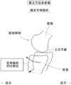
在图1中,示出了健康且正常的膝关节的侧视图。如图1所示那样,股骨的股骨髁部和胫骨的上关节面处于上下对置的关系。在图1中,前方的含义是指,以患者为基准的前方,后方的含义是指,以患者为基准的后方。In Figure 1, a side view of a healthy and normal knee joint is shown. As shown in FIG. 1 , the femoral condyle of the femur and the upper articular surface of the tibia are in an up-and-down relationship. In FIG. 1 , the front refers to the front based on the patient, and the rear refers to the back based on the patient.
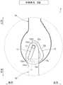
在图2中,示出了患有膝关节屈曲挛缩的膝关节的侧视图。如图2所示那样,在膝关节患有膝关节屈曲挛缩的情况下,胫骨的上关节面相对于股骨的股骨髁部而相对地向后方发生了偏移。在该状态下,当使膝关节伸展时,会妨碍胫骨的上关节面与股骨的股骨髁部之间的适当的滑动,从而在膝关节处产生疼痛。该伸展时的疼痛成为主要原因,使得患者很难接受以膝关节的伸展侧的可动范围扩展为目的的康复训练。In Figure 2, a side view of the knee joint with knee flexion contracture is shown. As shown in FIG. 2 , when the knee joint suffers from knee flexion contracture, the upper articular surface of the tibia is displaced relatively rearward with respect to the femoral condyle of the femur. In this state, when the knee joint is extended, proper sliding between the upper articular surface of the tibia and the femoral condyle of the femur is hindered, thereby causing pain at the knee joint. Pain at the time of this extension is a major factor, and it is difficult for the patient to receive rehabilitation training for the purpose of extending the range of motion on the extension side of the knee joint.
本发明的目的在于,提供一种缓解在患有膝关节屈曲挛缩的膝关节的伸展时所产生的疼痛的技术。An object of the present invention is to provide a technique for alleviating pain caused by extension of a knee joint suffering from flexion contracture of the knee joint.
用于解决课题的方法methods for solving problems
根据本申请发明的观点,提供一种膝部矫形器,具备:大腿佩戴部,其被佩戴在使用者的大腿上;小腿佩戴部,其被佩戴在所述使用者的小腿上;外侧单元,其对所述大腿佩戴部和所述小腿佩戴部进行连结,并且被配置于所述使用者的下肢的外侧(lateral)一侧;内侧单元,其对所述大腿佩戴部和所述小腿佩戴部进行连结,并且被配置于所述使用者的下肢的内侧(medial)一侧,在所述膝部矫形器中,所述外侧单元具有:大腿外侧连杆,其沿着所述大腿而延伸并通过所述大腿佩戴部从而被固定在所述大腿上;小腿外侧连杆,其沿着所述小腿而延伸并通过所述小腿佩戴部从而被固定在所述小腿上,所述大腿外侧连杆以及所述小腿外侧连杆在所述使用者的膝关节的外侧一侧处以相互能够旋转的方式被连结在一起,所述内侧单元具有:大腿内侧连杆,其沿着所述大腿而延伸并通过所述大腿佩戴部从而被固定在所述大腿上;小腿内侧连杆,其沿着所述小腿而延伸并通过所述小腿佩戴部从而被固定在所述小腿上,所述大腿内侧连杆以及所述小腿内侧连杆在所述使用者的膝关节的内侧一侧处以相互能够旋转的方式被连结在一起,所述外侧单元以及所述内侧单元被构成为,随着所述使用者的膝关节伸展,从而使所述小腿外侧连杆在所述小腿外侧连杆的长度方向上远离所述大腿外侧连杆,并且使所述小腿外侧连杆相对于所述大腿外侧连杆而相对地在与所述小腿外侧连杆的长度方向正交的方向上向前方被牵拉,而且,使所述小腿内侧连杆在所述小腿内侧连杆的长度方向上远离所述大腿内侧连杆,并且使所述小腿内侧连杆相对于所述大腿内侧连杆而相对地在与所述小腿内侧连杆的长度方向正交的方向上向前方被牵拉。根据以上的结构,能够缓解在患有膝关节屈曲挛缩的膝关节的伸展时所产生的疼痛。According to the viewpoint of the invention of the present application, there is provided a knee orthosis comprising: a thigh wearing part to be worn on the thigh of a user; a calf wearing part to be worn on the lower leg of the user; and an outer unit, It connects the thigh wearing part and the calf wearing part, and is arranged on the lateral side of the lower limb of the user; an inner unit connects the thigh wearing part and the calf wearing part connected and arranged on the medial side of the lower limb of the user, in the knee orthosis, the outer unit has a thigh outer link extending along the thigh and Passing through the thigh wearing part to be fixed on the thigh; a calf outer link extending along the calf and passing through the calf wearing part to be fixed on the calf, the thigh outer link and the calf outer links are mutually rotatably coupled together at the outer side of the user's knee joint, and the inner unit has an inner thigh link extending along the thigh and Through the thigh wearing part to be fixed on the thigh; a calf inner link extending along the calf and passing through the calf wearing part to be fixed on the calf, the inner thigh link and the inner calf link is rotatably connected to each other at the inner side of the user's knee joint, and the outer unit and the inner unit are configured so as to follow the user's movement. The knee joint is extended so that the outer calf link is distanced from the outer thigh link in the length direction of the outer calf link, and the outer calf link is opposite to the outer thigh link is pulled forward in a direction orthogonal to the longitudinal direction of the outer calf link, and the inner calf link is moved away from the inner thigh link in the longitudinal direction of the inner calf link, In addition, the inner calf link is pulled forward relative to the inner thigh link in a direction orthogonal to the longitudinal direction of the inner calf link. According to the above configuration, it is possible to relieve pain that occurs during extension of the knee joint suffering from flexion contracture of the knee joint.
优选为,在所述大腿外侧连杆上,形成有大腿凸轮,在所述小腿外侧连杆上形成有小腿销,所述小腿销以沿着所述大腿凸轮而移动的方式与所述大腿凸轮卡合,在所述小腿外侧连杆上,形成有小腿凸轮,在所述大腿外侧连杆上形成有大腿销,所述大腿销以沿着所述小腿凸轮而移动的方式与所述小腿凸轮卡合,所述小腿凸轮以随着远离所述小腿佩戴部而趋向后方的方式延伸,所述大腿凸轮被形成为,随着膝关节伸展而使所述小腿佩戴部远离所述大腿销。根据以上的结构,能够以简单的结构来实现上述的小腿外侧连杆的相对于大腿外侧连杆的相对运动。Preferably, a thigh cam is formed on the outer thigh link, and a shank pin is formed on the outer lower link link, and the lower leg pin is connected to the thigh cam so as to move along the thigh cam. For engagement, a calf cam is formed on the calf outer link, and a thigh pin is formed on the thigh outer link, and the thigh pin is connected to the calf cam so as to move along the calf cam. When engaged, the calf cam extends rearward as it moves away from the calf wearing portion, and the thigh cam is formed so as to move the calf wearing portion away from the thigh pin as the knee joint extends. According to the above configuration, the above-described relative movement of the outer calf link with respect to the outer thigh link can be realized with a simple configuration.
优选为,在所述大腿内侧连杆上,形成有大腿凸轮,在所述小腿内侧连杆上形成有小腿销,所述小腿销以沿着所述大腿凸轮而移动的方式与所述大腿凸轮卡合,在所述小腿内侧连杆上,形成有小腿凸轮,在所述大腿内侧连杆上形成有大腿销,所述大腿销以沿着所述小腿凸轮而移动的方式与所述小腿凸轮卡合,所述小腿凸轮以随着远离所述小腿佩戴部而趋向后方的方式延伸,所述大腿凸轮被形成为,随着膝关节伸展而使所述小腿佩戴部远离所述大腿销。根据以上的结构,能够以简单的结构来实现上述的小腿外侧连杆的相对于大腿外侧连杆的相对运动。Preferably, a thigh cam is formed on the inner thigh link, and a calf pin is formed on the inner calf link, and the calf pin is connected to the thigh cam so as to move along the thigh cam. For engagement, a calf cam is formed on the inner calf link, and a thigh pin is formed on the inner thigh link, and the thigh pin is connected to the calf cam so as to move along the calf cam. When engaged, the calf cam extends rearward as it moves away from the calf wearing portion, and the thigh cam is formed so as to move the calf wearing portion away from the thigh pin as the knee joint extends. According to the above configuration, the above-described relative movement of the outer calf link with respect to the outer thigh link can be realized with a simple configuration.
优选为,当定义为将膝关节处于伸展状态时的膝关节角度设为0度、且膝关节角度随着膝关节屈曲而增加时,所述大腿凸轮被形成为,在膝关节角度从90度朝向0度变化的期间内,使所述小腿佩戴部远离所述大腿销。根据以上的结构,能够在患有膝关节屈曲挛缩的膝关节的伸展时在产生疼痛的时候有效地缓解该疼痛。Preferably, when the knee joint angle when the knee joint is in an extended state is defined as 0 degrees and the knee joint angle increases as the knee joint is flexed, the thigh cam is formed so that the knee joint angle changes from 90 degrees. The calf-wearing portion is moved away from the thigh pin during the change toward 0 degrees. According to the above configuration, when pain occurs during extension of the knee joint suffering from flexion contracture of the knee joint, the pain can be effectively relieved.
优选为,所述大腿凸轮被形成为,在膝关节角度从60度朝向30度变化的期间内,使所述小腿佩戴部远离所述大腿销。根据以上的结构,能够在患有膝关节屈曲挛缩的膝关节的伸展时在产生疼痛的时候有效地缓解该疼痛。Preferably, the thigh cam is formed so as to keep the calf wearing portion away from the thigh pin while the knee joint angle changes from 60 degrees to 30 degrees. According to the above configuration, when pain occurs during extension of the knee joint suffering from flexion contracture of the knee joint, the pain can be effectively relieved.
优选为,在所述大腿外侧连杆上,形成有大腿凸轮,在所述小腿外侧连杆上形成有小腿销,所述小腿销以沿着所述大腿凸轮而移动的方式与所述大腿凸轮卡合,在所述小腿外侧连杆上,形成有小腿凸轮,在所述大腿外侧连杆上形成有大腿销,所述大腿销以沿着所述小腿凸轮而移动的方式与所述小腿凸轮卡合,所述大腿凸轮以随着远离所述大腿佩戴部而趋向前方的方式延伸,所述小腿凸轮被形成为,随着膝关节伸展而使所述小腿佩戴部远离所述大腿销。根据以上的结构,能够以简单的结构来实现上述的小腿外侧连杆的相对于大腿外侧连杆的相对运动。Preferably, a thigh cam is formed on the outer thigh link, and a shank pin is formed on the outer lower link link, and the lower leg pin is connected to the thigh cam so as to move along the thigh cam. For engagement, a calf cam is formed on the calf outer link, and a thigh pin is formed on the thigh outer link, and the thigh pin is connected to the calf cam so as to move along the calf cam. When engaged, the thigh cam extends forward as it moves away from the thigh-wearing portion, and the lower-leg cam is formed so as to move the lower-leg wearing portion away from the thigh pin as the knee joint extends. According to the above configuration, the above-described relative movement of the outer calf link with respect to the outer thigh link can be realized with a simple configuration.
优选为,在所述大腿内侧连杆上,形成有大腿凸轮,在所述小腿内侧连杆上形成有小腿销,所述小腿销以沿着所述大腿凸轮而移动的方式与所述大腿凸轮卡合,在所述小腿内侧连杆上,形成有小腿凸轮,在所述大腿内侧连杆上形成有大腿销,所述大腿销以沿着所述小腿凸轮而移动的方式与所述小腿凸轮卡合,所述大腿凸轮以随着远离所述大腿佩戴部而趋向前方的方式延伸,所述小腿凸轮被形成为,随着膝关节伸展而使所述小腿佩戴部远离所述大腿销。根据以上的结构,能够以简单的结构来实现上述的小腿外侧连杆的相对于大腿外侧连杆的相对运动。Preferably, a thigh cam is formed on the inner thigh link, and a calf pin is formed on the inner calf link, and the calf pin is connected to the thigh cam so as to move along the thigh cam. For engagement, a calf cam is formed on the inner calf link, and a thigh pin is formed on the inner thigh link, and the thigh pin is connected to the calf cam so as to move along the calf cam. When engaged, the thigh cam extends forward as it moves away from the thigh-wearing portion, and the lower-leg cam is formed so as to move the lower-leg wearing portion away from the thigh pin as the knee joint extends. According to the above configuration, the above-described relative movement of the outer calf link with respect to the outer thigh link can be realized with a simple configuration.
优选为,当定义为将膝关节处于伸展状态时的膝关节角度设为0度、且膝关节角度随着膝关节屈曲而增加时,所述小腿凸轮被形成为,在膝关节角度从90度朝向0度变化的期间内,使所述小腿佩戴部远离所述大腿销。根据以上的结构,能够在患有膝关节屈曲挛缩的膝关节的伸展时在产生疼痛的时候有效地缓解该疼痛。Preferably, when the knee joint angle when the knee joint is in an extended state is defined as 0 degrees and the knee joint angle increases as the knee joint is flexed, the lower leg cam is formed so that the knee joint angle changes from 90 degrees. The calf-wearing portion is moved away from the thigh pin during the change toward 0 degrees. According to the above configuration, when pain occurs during extension of the knee joint suffering from flexion contracture of the knee joint, the pain can be effectively relieved.
优选为,所述小腿凸轮被形成为,在膝关节角度从60度朝向30度变化的期间内,使所述小腿佩戴部远离所述大腿销。根据以上的结构,能够在患有膝关节屈曲挛缩的膝关节的伸展时在产生疼痛的时候有效地缓解该疼痛。Preferably, the calf cam is formed so as to keep the calf wearing portion away from the thigh pin while the knee joint angle changes from 60 degrees to 30 degrees. According to the above configuration, when pain occurs during extension of the knee joint suffering from flexion contracture of the knee joint, the pain can be effectively relieved.
优选为,提供一种具备上述的膝部矫形器的腿部矫形器。Preferably, a leg orthosis provided with the above-mentioned knee orthosis is provided.
发明效果Invention effect
根据本发明,能够缓解在患有膝关节屈曲挛缩的膝关节伸展时所产生的疼痛。According to the present invention, it is possible to relieve pain that occurs when a knee joint suffering from flexion contracture of the knee joint is extended.
本发明的上述和其他目的、特征和优点将从下文给出的详细描述和仅作为说明方式而给出的附图中得到更充分的理解,因此不应被视为是对本发明的限制。The above and other objects, features and advantages of the present invention will be more fully understood from the detailed description given hereinafter and the accompanying drawings, which are given by way of illustration only and should therefore not be construed as limiting the invention.
附图说明Description of drawings
图1为健康且正常的膝关节的侧视图。Figure 1 is a side view of a healthy and normal knee joint.
图2为患有膝关节屈曲挛缩的膝关节的侧视图。Figure 2 is a side view of a knee joint with knee flexion contracture.
图3为表示在伸展患有膝关节屈曲挛缩的膝关节时缓解疼痛的方法的侧视图。Figure 3 is a side view showing a method of pain relief when extending a knee joint suffering from knee flexion contracture.
图4为腿部矫形器的立体图。(第一实施方式)Figure 4 is a perspective view of the leg orthosis. (first embodiment)
图5为外侧单元的分解侧视图。(第一实施方式)Figure 5 is an exploded side view of the outer unit. (first embodiment)
图6为膝关节角度为0度时的外侧单元的局部侧视图。(第一实施方式)6 is a partial side view of the lateral unit when the knee joint angle is 0 degrees. (first embodiment)
图7为膝关节角度为30度时的外侧单元的局部侧视图。(第一实施方式)7 is a partial side view of the lateral unit when the knee joint angle is 30 degrees. (first embodiment)
图8为膝关节角度为60度时的外侧单元的局部侧视图。(第一实施方式)8 is a partial side view of the lateral unit when the knee joint angle is 60 degrees. (first embodiment)
图9为膝关节角度为90度时的外侧单元的局部侧视图。(第一实施方式)9 is a partial side view of the lateral unit when the knee joint angle is 90 degrees. (first embodiment)
图10为膝关节角度为120度时的外侧单元的局部侧视图。(第一实施方式)10 is a partial side view of the lateral unit when the knee joint angle is 120 degrees. (first embodiment)
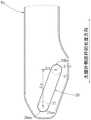
图11为小腿外侧连杆的侧视图。(第一实施方式)Figure 11 is a side view of the outer calf link. (first embodiment)
图12为表示膝关节角度和位移量的关系的曲线图。FIG. 12 is a graph showing the relationship between the knee joint angle and the displacement amount.
图13为外侧单元的分解侧视图。(第二实施方式)Figure 13 is an exploded side view of the outer unit. (Second Embodiment)
图14为膝关节角度为0度时的外侧单元的局部侧视图。(第二实施方式)14 is a partial side view of the lateral unit when the knee joint angle is 0 degrees. (Second Embodiment)
图15为膝关节角度为30度时的外侧单元的局部侧视图。(第二实施方式)15 is a partial side view of the lateral unit when the knee joint angle is 30 degrees. (Second Embodiment)
图16为膝关节角度为60度时的外侧单元的局部侧视图。(第二实施方式)Fig. 16 is a partial side view of the lateral unit when the knee joint angle is 60 degrees. (Second Embodiment)
图17为膝关节角度为90度时的外侧单元的局部侧视图。(第二实施方式)17 is a partial side view of the lateral unit when the knee joint angle is 90 degrees. (Second Embodiment)
图18为膝关节角度为120度时的外侧单元的局部侧视图。(第二实施方式)18 is a partial side view of the lateral unit when the knee joint angle is 120 degrees. (Second Embodiment)
图19为大腿外侧连杆的侧视图。(第二实施方式)Figure 19 is a side view of the outer thigh link. (Second Embodiment)
具体实施方式Detailed ways
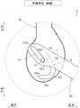
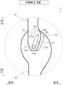
本申请发明的发明人们经过潜心研究,得到了如下见解,即,在实施以患有膝关节屈曲挛缩的膝关节的伸展侧的可动范围扩展为目的的康复训练时,如图3所示那样,如果在膝关节伸展时有意识地向下方以及前方牵拉胫骨,则能够缓解在康复训练时所产生的膝关节的疼痛。The inventors of the present invention have made intensive studies and have come to the knowledge that, when performing rehabilitation training for the purpose of expanding the range of motion on the extension side of the knee joint suffering from flexion contracture of the knee joint, as shown in FIG. 3 . , If the tibia is consciously pulled downward and forward when the knee joint is extended, the pain of the knee joint during rehabilitation training can be relieved.
也就是说,如图3所示那样,通过在膝关节的伸展时向下方牵拉胫骨,从而可扩展股骨的股骨髁部与胫骨的上关节面之间的间隙。在此,所谓“在膝关节的伸展时向下方牵拉胫骨”的含义是指,在膝关节的伸展时,在胫骨的长度方向上向脚侧牵拉胫骨。That is, as shown in FIG. 3 , by pulling the tibia downward when the knee joint is extended, the gap between the femoral condyle of the femur and the upper articular surface of the tibia can be expanded. Here, the meaning of "pulling the tibia downward when the knee joint is extended" means that the tibia is pulled toward the foot side in the longitudinal direction of the tibia when the knee joint is extended.
此外,通过在膝关节的伸展时向前方牵拉胫骨,从而对于患有膝关节屈曲挛缩的膝关节而言,典型性的胫骨的上关节面的相对于股骨髁部的不适当的位置关系被暂时性地恢复为适当的位置关系。在此,所谓“在膝关节的伸展时向前方牵拉胫骨”的含义是指,在膝关节的伸展时,在与胫骨的长度方向正交的方向上向前方牵拉胫骨。Furthermore, the inappropriate positional relationship of the superior articular surface of the tibia with respect to the femoral condyle typical of a knee joint with knee flexion contracture is prevented by pulling the tibia anteriorly during extension of the knee joint. Temporarily revert to the proper positional relationship. Here, the meaning of "pulling the tibia forward during the extension of the knee joint" means that the tibia is pulled forward in a direction orthogonal to the longitudinal direction of the tibia during the extension of the knee joint.
以此方式,通过在膝关节的伸展时有意识地向下方以及前方牵拉胫骨,从而能够在股骨的股骨髁部与胫骨的上关节面之间形成适度的间隙,并且针对腿骨的股骨髁部而改善胫骨的上关节面的位置关系,从而使两者不会发生物理性地干涉,其结果为,能够缓解在以膝关节的伸展侧的可动范围扩展为目的的康复训练时所产生的膝关节的疼痛。In this way, by consciously pulling the tibia downward and anterior during the extension of the knee joint, a moderate gap can be formed between the femoral condyle of the femur and the upper articular surface of the tibia, and the femoral condyle of the leg can be targeted. In addition, the positional relationship of the upper articular surface of the tibia is improved so that the two do not interfere physically. As a result, it is possible to alleviate the occurrence of rehabilitation training for the purpose of expanding the range of motion on the extension side of the knee joint. Knee pain.
但是,上述的见解是以在膝关节的伸展时向下方以及前方牵拉胫骨为前提的,同时实施这三个动作是比较困难的,在徒手疗法中,最终很难实现。However, the above-mentioned knowledge is based on the premise that the tibia is pulled downward and forward during the extension of the knee joint, and it is difficult to perform these three movements at the same time, and it is ultimately difficult to achieve in the manual therapy.
因此,本申请发明的发明人们发明了无论是谁都能够很简单地实现上述三个动作,进一步而言,即使是患者本身也能够单独地实现上述三个动作的膝部矫形器。Therefore, the inventors of the present invention have invented a knee orthosis that can easily realize the above-mentioned three movements for anyone, and further, even the patient himself can realize the above-mentioned three movements alone.
以下,关于应用了本发明的具体的实施方式,将在参照附图的同时进行详细地说明。但是,本发明并非被限定于以下的实施方式。此外,为了明确说明,以下的记载以及附图被适当地简化了。Hereinafter, specific embodiments to which the present invention is applied will be described in detail with reference to the accompanying drawings. However, the present invention is not limited to the following embodiments. In addition, the following description and drawings are appropriately simplified for the sake of clarity.
(第一实施方式)(first embodiment)
首先,参照图4,对第一实施方式的腿部矫形器1进行说明。First, the leg orthosis 1 of the first embodiment will be described with reference to FIG. 4 .
在图4中,示出了佩戴于使用者的左腿L上的腿部矫形器1。在图4中,用双点划线示出了使用者的左腿L,并用单点划线示出了使用者所穿的鞋。In Figure 4, the leg orthosis 1 is shown worn on the left leg L of the user. In FIG. 4 , the user's left leg L is shown with a double-dot chain line, and the shoes worn by the user are shown with a single-dot chain line.
如图4所示那样,腿部矫形器1具备膝部矫形器2和小腿辅助用具3。膝部矫形器2为,被佩戴在患有变形性膝关节炎的左腿L上,并且缓解在患有膝关节屈曲挛缩的膝关节的伸展时所产生的疼痛的矫形器。膝部矫形器2在被佩戴于左腿L上的状态下,以追随于膝关节的屈伸的方式而进行屈伸。小腿辅助用具3对使用者的膝关节的推力进行抑制。关于小腿辅助用具3,将省略说明。另外,小腿辅助用具3以能够相对于膝部矫形器2而进行拆装的方式被构成。因此,能够将小腿辅助用具3从膝部矫形器2上拆卸下来,并单独地使用膝部矫形器2。As shown in FIG. 4 , the leg orthosis 1 includes a
膝部矫形器2包括:大腿佩戴部4、小腿佩戴部5、外侧单元6、内侧单元7。The
大腿佩戴部4被佩戴在使用者的左腿L的大腿L1上。大腿佩戴部4包括大腿箍4a和大腿带4b。The thigh wearing part 4 is worn on the thigh L1 of the left leg L of the user. The thigh wearing portion 4 includes a
大腿箍4a以与使用者的大腿L1的前表面对置的方式被配置。大腿箍4a以在俯视观察时向前方凸出的方式弯曲。大腿带4b通过以同时缠住使用者的大腿L1和大腿箍4a的方式缠绕在使用者的大腿L1上,从而将大腿箍4a固定在使用者的大腿L1上。The
小腿佩戴部5被佩戴在使用者的左腿L的小腿L2上。小腿佩戴部5包括小腿箍5a和小腿带5b。The
小腿箍5a以与使用者的小腿L2的前表面对置的方式被配置。小腿箍5a以在俯视观察时向前方凸出的方式弯曲。小腿带5b通过以同时缠住使用者的小腿L2和小腿箍5a的方式缠绕在使用者的小腿L2上,从而将小腿箍5a固定在使用者的小腿L2上。The
外侧单元6对大腿佩戴部4和小腿佩戴部5进行连结,并且被配置在使用者的左腿L(下肢)的外侧(lateral)。The
外侧单元6具有大腿外侧连杆6a和小腿外侧连杆6b,所述大腿外侧连杆6a沿着大腿L1延伸并通过大腿佩戴部4而被固定在大腿L1上,所述小腿外侧连杆6b沿着小腿L2延伸并通过小腿佩戴部5而被固定在小腿L2上。大腿外侧连杆6a以及小腿外侧连杆6b在使用者的膝关节的外侧一侧以能够旋转的方式被相互连结在一起。The
内侧单元7对大腿佩戴部4和小腿佩戴部5进行连结,并且被配置在使用者的左腿L(下肢)的内侧(medial)。The inner unit 7 connects the thigh wearing part 4 and the
内侧单元7具有大腿内侧连杆7a和小腿内侧连杆7b,所述大腿内侧连杆7a沿着大腿L1延伸并通过大腿佩戴部4而被固定在大腿L1上,所述小腿内侧连杆7b沿着小腿L2延伸并通过小腿佩戴部5而被固定在小腿L2上。大腿内侧连杆7a以及小腿内侧连杆7b在使用者的膝关节的内侧一侧以能够旋转的方式被相互连结在一起。The inner unit 7 includes an
而且,外侧单元6被构成为,随着使用者的膝关节伸展,从而小腿外侧连杆6b在小腿外侧连杆6b的长度方向上远离大腿外侧连杆6a,并且小腿外侧连杆6b相对于大腿外侧连杆6a而相对地在与小腿外侧连杆6b的长度方向正交的方向上被向前方拉出。同样地,内侧单元7被构成为,随着使用者的膝关节伸展,从而小腿内侧连杆7b在小腿内侧连杆7b的长度方向上远离大腿内侧连杆7a,并且小腿内侧连杆7b相对于大腿内侧连杆7a而相对地在与小腿内侧连杆7b的长度方向正交的方向上被向前方拉出。具体内容如下所述。Further, the
(外侧单元6)(outside unit 6)
以下,参照图5至图11,对大腿外侧连杆6a和小腿外侧连杆6b的连结部分进行详细地说明。Hereinafter, referring to FIGS. 5 to 11 , the connection portion between the outer thigh link 6 a and the
在图5中,示出了将小腿外侧连杆6b从大腿外侧连杆6a上拆卸下来的状态。在图6中,示出了将小腿外侧连杆6b安装在大腿外侧连杆6a上的状态。In FIG. 5, the state which removed the calf
如图5以及图6所示那样,在大腿外侧连杆6a上,形成有大腿凸轮10。在小腿外侧连杆6b上,形成有以沿着大腿凸轮10而移动的方式与大腿凸轮10卡合的小腿销11。在小腿外侧连杆6b上,形成有小腿凸轮12。在大腿外侧连杆6a上,形成有以沿着小腿凸轮12而移动的方式与小腿凸轮12卡合的大腿销13。As shown in FIGS. 5 and 6 , a
如图6所示那样,小腿外侧连杆6b被配置于大腿外侧连杆6a的外侧一侧(朝向纸面而靠外侧)。但是,小腿外侧连杆6b也可以配置于大腿外侧连杆6a的内侧一侧(朝向纸面而靠里侧)。As shown in FIG. 6, the calf
如图5所示那样,小腿销11朝向内侧一侧突出,大腿销13朝向外侧一侧突出。As shown in FIG. 5 , the
大腿凸轮10被形成为,在大腿外侧连杆6a的板厚方向上未贯穿大腿外侧连杆6a的槽状。但是,大腿凸轮10也可以形成为,在大腿外侧连杆6a的板厚方向上贯穿大腿外侧连杆6a的狭缝状。The
小腿凸轮12被形成为,在小腿外侧连杆6b的板厚方向上贯穿小腿外侧连杆6b的狭缝状。但是,小腿凸轮12也可以形成为,在小腿外侧连杆6b的板厚方向上未贯穿小腿外侧连杆6b的槽状。The
在该结构中,如图6至图10所示那样,当使小腿外侧连杆6b相对于大腿外侧连杆6a而进行旋转时,大腿销13将沿着小腿凸轮12进行移动,并且小腿销11沿着大腿凸轮10进行移动。即,通过大腿凸轮10、小腿销11、小腿凸轮12、大腿销13的协同工作,从而使外侧单元6被构成为能够追随于膝关节的屈伸而进行屈伸。In this configuration, as shown in FIGS. 6 to 10 , when the
以下,在对大腿凸轮10、小腿销11、小腿凸轮12、大腿销13的配置或形状进行说明时,如图5所示那样,设为大腿外侧连杆6a以及小腿外侧连杆6b均是沿着上下方向而延伸的姿态。Hereinafter, when the arrangement and shape of the
如图5所示那样,小腿凸轮12以随着远离小腿佩戴部5而趋向后方的方式延伸。小腿凸轮12以随着趋向上方而趋向后方的方式延伸。小腿凸轮12相对于小腿凸轮12的长度方向而倾斜。小腿凸轮12直线延伸。但是,小腿凸轮12既可以以向前方凸出的方式弯曲,也可以以向后方凸出的方式弯曲。小腿凸轮12具有伸展侧端部12ex和屈曲侧端部12bn。伸展侧端部12ex为,在膝关节伸展而使膝关节角度成为0度时大腿销13所位于的端部。屈曲侧端部12bn为,在膝关节屈曲而使膝关节角度成为120度时大腿销13所位于的端部。因此,当使膝关节伸展时,大腿销13从屈曲侧端部12bn朝向伸展侧端部12ex进行移动。相反地,当使膝关节屈曲时,大腿销13从伸展侧端部12ex朝向屈曲侧端部12bn进行移动。As shown in FIG. 5 , the
小腿销11被配置在与小腿凸轮12相比靠下方处。小腿销11被配置在与小腿凸轮12相比靠小腿佩戴部5的附近处。因此,在大腿销13位于小腿凸轮12的屈曲侧端部12bn时,大腿销13最接近小腿销11。相反地,在大腿销13位于小腿凸轮12的伸展侧端部12ex时,大腿销13最远离小腿销11。The
继续如图5所示那样,大腿凸轮10被形成为,随着膝关节伸展而使小腿佩戴部5远离大腿销13。换而言之,大腿凸轮10被形成为发挥如下功能,即,随着膝关节伸展而使小腿佩戴部5远离大腿销13的功能。Continuing as shown in FIG. 5 , the
具体而言,大腿凸轮10以包围大腿销13的方式弯曲并延伸。大腿凸轮10弯曲成朝向前方而开口的U字状。大腿凸轮10具有伸展侧端部10ex和屈曲侧端部10bn。伸展侧端部10ex为,在膝关节伸展而使膝关节角度成为0度时小腿销11所位于的端部。屈曲侧端部10bn为,在膝关节屈曲而使膝关节角度成为120度时小腿销11所位于的端部。因此,当使膝关节伸展时,小腿销11将从屈曲侧端部10bn朝向伸展侧端部10ex进行移动。相反地,当使膝关节屈曲时,小腿销11将从伸展侧端部10ex朝向屈曲侧端部10bn进行移动。大腿凸轮10包括屈曲凸轮部10a、过渡直线凸轮部10b、过渡弯曲凸轮部10c、伸展凸轮部10d。屈曲凸轮部10a包括屈曲侧端部10bn。伸展凸轮部10d包括伸展侧端部10ex。屈曲凸轮部10a和过渡直线凸轮部10b、过渡弯曲凸轮部10c、伸展凸轮部10d按照该记载的顺序而连接。因此,屈曲凸轮部10a和过渡直线凸轮部10b、过渡弯曲凸轮部10c、伸展凸轮部10d以从屈曲侧端部10bn朝向伸展侧端部10ex的方式按照该记载的顺序而连接。在图5中,用双点划线示出了屈曲凸轮部10a和过渡直线凸轮部10b的边界、过渡直线凸轮部10b和过渡弯曲凸轮部10c的边界、过渡弯曲凸轮部10c和伸展凸轮部10d的边界。Specifically, the
屈曲凸轮部10a被配置于大腿销13的上方,并且延伸为以大腿销13为中心的圆弧状。即,屈曲凸轮部10a以朝向上方而凸出的方式弯曲。The bending
过渡直线凸轮部10b被配置于大腿销13的后方,并且直线地延伸。过渡直线凸轮部10b以随着趋向下方而趋向后方的方式延伸。因此,过渡直线凸轮部10b被形成为,随着从屈曲侧端部10bn侧趋向伸展侧端部10ex侧而远离大腿销13。The transition
过渡弯曲凸轮部10c被配置于大腿销13的下方以及后方,并且延伸为以位于与大腿销13相比靠下方的弯曲中心10cc为中心的圆弧状。即,过渡弯曲凸轮部10c以向远离大腿销13的方向而凸出的方式,换而言之,以朝向下方以及后方而凸出的方式弯曲。因此,过渡弯曲凸轮部10c被形成为,随着从屈曲侧端部10bn侧趋向伸展侧端部10ex侧而远离大腿销13。The transitional
伸展凸轮部10d被配置于大腿销13的下方,并且直线地延伸。伸展凸轮部10d在前后方向上延伸。因此,伸展凸轮部10d随着从屈曲侧端部10bn侧趋向伸展侧端部10ex侧而稍接近大腿销13,并在之后稍远离大腿销13。The
接下来,参照图6至图10,对大腿凸轮10、小腿销11、小腿凸轮12、大腿销13是如何根据膝关节角度来联动的进行说明。Next, how the
(膝关节角度:0度)(Knee joint angle: 0 degrees)
如图6所示那样,在膝关节角度为0度时,也就是在膝关节以及外侧单元6处于伸展状态时,大腿销13位于小腿凸轮12的伸展侧端部12ex,小腿销11位于大腿凸轮10的伸展凸轮部10d的伸展侧端部10ex。As shown in FIG. 6 , when the knee joint angle is 0 degrees, that is, when the knee joint and the
以此方式,由于在膝关节角度为0度时,小腿销11位于伸展凸轮部10d处,且伸展凸轮部10d在前后方向上延伸,因此不会因佩戴了膝部矫形器2的患病的腿着地时受到的地面反作用力而使小腿销11朝向大腿凸轮10的过渡弯曲凸轮部10c移动。因此,在佩戴了膝部矫形器2的患病的腿着地时,维持了膝关节以及外侧单元6的伸展状态。In this way, since the
(膝关节角度:30度)(Knee joint angle: 30 degrees)
如图7所示那样,在膝关节角度为30度时,大腿销13位于小腿凸轮12的伸展侧端部12ex,小腿销11位于大腿凸轮10的过渡弯曲凸轮部10c。As shown in FIG. 7 , when the knee joint angle is 30 degrees, the
(膝关节角度:60度)(Knee joint angle: 60 degrees)
如图8所示那样,在膝关节角度为60度时,大腿销13位于小腿凸轮12的屈曲侧端部12bn,小腿销11位于大腿凸轮10的屈曲凸轮部10a和过渡直线凸轮部10b的边界处。As shown in FIG. 8 , when the knee joint angle is 60 degrees, the
(膝关节角度:90度)(Knee joint angle: 90 degrees)
如图9所示那样,在膝关节角度为90度时,大腿销13位于小腿凸轮12的屈曲侧端部12bn,小腿销11位于大腿凸轮10的屈曲凸轮部10a。As shown in FIG. 9 , when the knee joint angle is 90 degrees, the
(膝关节角度:120度)(Knee joint angle: 120 degrees)
如图10所示那样,在膝关节角度为120度时,大腿销13位于小腿凸轮12的屈曲侧端部12bn,小腿销11位于大腿凸轮10的屈曲凸轮部10a的屈曲侧端部10bn。As shown in FIG. 10 , when the knee joint angle is 120 degrees, the
(膝关节角度:120度→60度)(Knee joint angle: 120 degrees → 60 degrees)
如图8至图10所示那样,在膝关节伸展从而使膝关节角度从120度向60度变化的期间内,小腿销11以沿着大腿凸轮10的屈曲凸轮部10a而远离屈曲侧端部10bn的方式进行移动。另一方面,大腿凸轮10的屈曲凸轮部10a延伸为以大腿销13为中心的圆弧状。因此,如图8至图10所示那样,在使膝关节伸展从而使膝关节角度从120度向60度变化的期间内,大腿销13维持被约束在小腿凸轮12的屈曲侧端部12bn的状态。即,小腿外侧连杆6b以大腿销13为中心而进行60度旋转。As shown in FIGS. 8 to 10 , during the period in which the knee joint is extended and the knee joint angle is changed from 120 degrees to 60 degrees, the
(膝关节角度:60度→30度)(Knee joint angle: 60 degrees → 30 degrees)
如图7以及图8所示那样,在膝关节伸展从而使膝关节角度从60度向30度变化的期间内,小腿销11以沿着大腿凸轮10的过渡直线凸轮部10b以及过渡弯曲凸轮部10c而远离屈曲侧端部10bn的方式进行移动。另一方面,大腿凸轮10被形成为,随着从大腿凸轮10的过渡直线凸轮部10b趋向于过渡弯曲凸轮部10c从而远离大腿销13。因此,如图7以及图8所示那样,在使膝关节伸展从而使膝关节从60度向30度变化的期间内,大腿销13从小腿凸轮12的屈曲侧端部12bn移动至伸展侧端部12ex。其结果为,并非是小腿外侧连杆6b以大腿销13为中心而单纯地旋转30度,而是除了该旋转之外,还在使膝关节伸展从而使膝关节从60度变化为30度的期间内,使小腿外侧连杆6b在小腿外侧连杆6b的长度方向上远离大腿外侧连杆6a,并且使小腿外侧连杆6b相对于大腿外侧连杆6a而相对地在与小腿外侧连杆6b的长度方向正交的方向上向前方被牵拉。在此,所谓“向前方”能够换一种表达为,“向左腿L从站立状态变为起脚状态时左腿L的小腿L2被摆出的方向”或“向脚尖侧”。As shown in FIGS. 7 and 8 , while the knee joint is extended to change the knee joint angle from 60 degrees to 30 degrees, the
在图11中,示出了在使膝关节伸展从而使膝关节从60度向30度变化的期间内,小腿外侧连杆6b在小腿外侧连杆6b的长度方向上离开大腿外侧连杆6a的位移量Δy、和小腿外侧连杆6b相对于大腿外侧连杆6a而相对地在与小腿外侧连杆6b的长度方向正交的方向上向前方被牵拉的位移量Δx。In FIG. 11 , during the period in which the knee joint is extended to change the knee joint from 60 degrees to 30 degrees, the
位移量Δy相当于小腿外侧连杆6b的长度方向上的大腿销13位于屈曲侧端部12bn时的大腿销13的中心点13bn与大腿销13位于伸展侧端部12ex时的大腿销13的中心点13ex之间的差值。The displacement amount Δy corresponds to the center point 13bn of the
相对于此,位移量Δx相当于在与小腿外侧连杆6b的长度方向正交的方向上的大腿销13位于屈曲侧端部12bn时的大腿销13的中心点13bn与大腿销13位于伸展侧端部12ex时的大腿销13的中心点13ex之间的差值。On the other hand, the displacement amount Δx corresponds to the center point 13bn of the
根据图11,通过对小腿凸轮12相对于小腿外侧连杆6b的长度方向的倾斜角度进行调节,从而能够对位移量Δx和位移量Δy的比例进行调节。此外,通过对小腿凸轮12的长度进行调节,从而能够在原样维持位移量Δx和位移量Δy的比例的条件下增减位移量Δx和位移量Δy。11 , by adjusting the inclination angle of the
在图12中,示出了对膝关节角度和位移量Δx以及位移量Δy的关系进行例示的曲线图。如图12所示那样,当使膝关节伸展时,位移量Δx以及位移量Δy在膝关节角度从60度向30度变化的期间内增加。具体而言,在上述区间内,位移量Δx成为8.5mm,位移量Δy成为23.5mm。此外,在图12的示例中,优选为,在膝关节角度为90度时,典型而言,在使用者坐在椅子上的状态下,将腿部矫形器1佩戴在使用者的左腿L上。图12所示的位移量Δx以及位移量Δy特别变化的膝关节角度的区间或其位移量、将腿部矫形器1佩戴在使用者的左腿L上时的上述的膝关节角度归根结底只不过为一个示例,并未被限定为这些内容。FIG. 12 shows a graph illustrating the relationship between the knee joint angle, the displacement amount Δx, and the displacement amount Δy. As shown in FIG. 12 , when the knee joint is extended, the displacement amount Δx and the displacement amount Δy increase while the knee joint angle changes from 60 degrees to 30 degrees. Specifically, in the above-mentioned section, the displacement amount Δx is 8.5 mm, and the displacement amount Δy is 23.5 mm. In addition, in the example of FIG. 12, it is preferable to wear the leg orthosis 1 on the left leg L of the user in a state where the user sits on a chair when the knee joint angle is 90 degrees, typically superior. The range of the knee joint angle in which the displacement amount Δx and the displacement amount Δy shown in FIG. 12 change in particular, or the displacement amount thereof, and the above-mentioned knee joint angle when the leg orthosis 1 is worn on the left leg L of the user are, in the final analysis, only It is an example and is not limited to these contents.
(膝关节角度:30度→0度)(Knee joint angle: 30 degrees → 0 degrees)
如图6以及图7所示那样,在膝关节伸展从而使膝关节角度从30度向0度变化的期间内,小腿销11以沿着大腿凸轮10的伸展凸轮部10d而接近伸展侧端部10ex的方式进行移动。另一方面,大腿凸轮10的伸展凸轮部10d和大腿销13之间的距离在伸展凸轮部10d的整个区域内几乎不发生变化。因此,如图6以及图7所示那样,在使膝关节伸展从而使膝关节从30度向0度变化的期间内,大腿销13维持实质上被约束在小腿凸轮12的伸展侧端部12ex的状态。即,小腿外侧连杆6b以大腿销13为中心而进行30度旋转。As shown in FIGS. 6 and 7 , while the knee joint is extended and the knee joint angle is changed from 30 degrees to 0 degrees, the
(内侧单元7)(inside unit 7)
由于图4所示的内侧单元7的结构相对于左腿L的正中而与外侧单元6的结构对称,因此省略其详细说明。Since the structure of the inner unit 7 shown in FIG. 4 is symmetrical with the structure of the
总而言之,内侧单元7以如下方式被构成。在大腿内侧连杆7a上,形成有大腿凸轮。在小腿内侧连杆7b上形成有小腿销,所述小腿销以沿着大腿凸轮而移动的方式与大腿凸轮卡合。在小腿内侧连杆7b上,形成有小腿凸轮。在大腿内侧连杆7a上形成有大腿销,所述大腿销以沿着小腿凸轮而移动的方式与小腿凸轮卡合。小腿凸轮以随着远离小腿佩戴部5而趋向后方的方式延伸。大腿凸轮被形成为,随着膝关节伸展而使小腿佩戴部远离大腿销。In summary, the inner unit 7 is configured as follows. A thigh cam is formed on the
根据以上的结构,仅将腿部矫形器1佩戴在患病的腿上,就能够实现在膝关节的伸展时有意地向下方以及前方牵拉胫骨的动作,从而如图3所示那样,在股骨的股骨髁部与胫骨的上关节面之间形成适度的间隙,并且胫骨的上关节面不会相对于股骨的股骨髁部而发生物理性地干涉,其结果为,缓解了在康复训练时所产生的膝关节的疼痛。According to the above structure, only by wearing the leg orthosis 1 on the diseased leg, it is possible to intentionally pull the tibia downward and forward when the knee joint is extended, so that as shown in FIG. A moderate gap is formed between the femoral condyle of the femur and the upper articular surface of the tibia, and the upper articular surface of the tibia does not physically interfere with the femoral condyle of the femur. Pain in the knee joint.
以上,虽然对第一实施方式进行了说明,但上述实施方式具有以下特征。Although the first embodiment has been described above, the above-described embodiment has the following features.
膝部矫形器2具备:大腿佩戴部4,其被佩戴在使用者的大腿L1上;小腿佩戴部5,其被佩戴在使用者的小腿L2上;外侧单元6,其对大腿佩戴部4和小腿佩戴部5进行连结,并且被配置于使用者的左腿L(下肢)的外侧(lateral);内侧单元7,其对大腿佩戴部4和小腿佩戴部5进行连结,并且被配置于使用者的左腿L的内侧(medial)。外侧单元6具有;大腿外侧连杆6a,其沿着大腿L1延伸并通过大腿佩戴部4而被固定在大腿L1上;小腿外侧连杆6b,其沿着小腿L2延伸并通过小腿佩戴部5而被固定在小腿L2上。大腿外侧连杆6a以及小腿外侧连杆6b在使用者的膝关节的外侧一侧处以能够旋转的方式被相互连结在一起。内侧单元7具有:大腿内侧连杆7a,其沿着大腿L1延伸并通过大腿佩戴部4而被固定在大腿L1上;小腿内侧连杆7b,其沿着小腿L2延伸并通过小腿佩戴部5而被固定在小腿L2上。大腿内侧连杆7a以及小腿内侧连杆7b在使用者的膝关节的内侧一侧处以能够旋转的方式被相互连结在一起。外侧单元6被构成为,随着使用者的膝关节伸展,从而使小腿外侧连杆6b在小腿外侧连杆6b的长度方向上远离大腿外侧连杆6a,并且使小腿外侧连杆6b相对于大腿外侧连杆6a而相对地在与小腿外侧连杆6b的长度方向正交的方向上向前方被牵拉。内侧单元7被构成为,随着使用者的膝关节伸展,从而使小腿内侧连杆7b在小腿内侧连杆7b的长度方向上远离大腿内侧连杆7a,并且使小腿内侧连杆7b相对于大腿内侧连杆7a而相对地在与小腿内侧连杆7b的长度方向正交的方向上向前方被牵拉。根据以上的结构,能够缓解在患有膝关节屈曲挛缩的膝关节伸展时所产生的疼痛。The
另外,如图5所示那样,在大腿外侧连杆6a上,形成有大腿凸轮10。在小腿外侧连杆6b上形成有小腿销11,所述小腿销11以沿着大腿凸轮10而移动的方式与大腿凸轮10卡合。在小腿外侧连杆6b上,形成有小腿凸轮12。在大腿外侧连杆6a上形成有大腿销13,所述大腿销13以沿着小腿凸轮12而移动的方式与小腿凸轮12卡合。小腿凸轮12以随着远离小腿佩戴部5而趋向后方的方式延伸。大腿凸轮10被形成为,随着膝关节伸展而使小腿佩戴部5远离大腿销13。根据以上的结构,能够以简单的结构来实现上述的小腿外侧连杆6b的相对于大腿外侧连杆6a的相对运动。Moreover, as shown in FIG. 5, the
此外,如图12所示那样,如果定义为,将膝关节处于伸展状态时的膝关节角度设为0度,且膝关节角度随着膝关节屈曲而增加,则优选为,大腿凸轮10被形成为,在膝关节角度从90度向0度变化的期间内,使小腿佩戴部5远离大腿销13。更具体而言,优选为,大腿凸轮10被形成为,在膝关节角度从60度向30度变化的期间内,使小腿佩戴部5远离大腿销13。作为一个示例,想要着眼于图12的位移量Δy。根据以上的结构,由于在患有膝关节屈曲挛缩的膝关节的伸展时在产生疼痛的时候位移量Δy增加,因此能够有效地缓解该疼痛。Further, as shown in FIG. 12 , if the knee joint angle when the knee joint is in an extended state is defined as 0 degrees, and the knee joint angle increases as the knee joint is flexed, it is preferable that the
(第二实施方式)(Second Embodiment)
接下来,参照图13至图19,对第二实施方式的腿部矫形器1进行说明。以下,以本实施方式与上述第一实施方式的不同点为中心来进行说明,并且省略重复的说明。Next, the leg orthosis 1 of the second embodiment will be described with reference to FIGS. 13 to 19 . Hereinafter, the difference between the present embodiment and the above-described first embodiment will be mainly described, and overlapping descriptions will be omitted.
相对于上述第一实施方式而言,在本实施方式中,大腿外侧连杆6a和小腿外侧连杆6b的连结部分有所不同。Compared with the above-described first embodiment, in this embodiment, the connection portion between the
在图13中,示出了将小腿外侧连杆6b从大腿外侧连杆6a上拆卸下来的状态。在图14中,示出了将小腿外侧连杆6b安装在大腿外侧连杆6a上的状态。In FIG. 13, the state which removed the calf
如图13以及图14所示那样,在大腿外侧连杆6a上,形成有大腿凸轮20。在小腿外侧连杆6b上形成有小腿销21,所述小腿销21以沿着大腿凸轮20而移动的方式与大腿凸轮20卡合。在小腿外侧连杆6b上,形成有小腿凸轮22。在大腿外侧连杆6a上形成有大腿销23,所述大腿销23以沿着小腿凸轮22而移动的方式与小腿凸轮22卡合。As shown in FIGS. 13 and 14 , a
如图14所示那样,小腿外侧连杆6b被配置于大腿外侧连杆6a的内侧(朝向纸面而靠里侧)。但是,小腿外侧连杆6b也可以配置于大腿外侧连杆6a的外侧(朝向纸面而靠外侧)。As shown in FIG. 14, the calf
如图13所示那样,小腿销21朝向外侧一侧突出,大腿销13朝向内侧一侧突出。As shown in FIG. 13 , the
大腿凸轮20被形成为,在大腿外侧连杆6a的板厚方向上贯穿大腿外侧连杆6a的狭缝状。但是,大腿凸轮20也可以形成为,在大腿外侧连杆6a的板厚方向上未贯穿大腿外侧连杆6a的槽状。The
小腿凸轮22被形成为,在小腿外侧连杆6b的板厚方向上未贯穿小腿外侧连杆6b的槽状。但是,小腿凸轮22也可以形成为,在小腿外侧连杆6b的板厚方向上贯穿小腿外侧连杆6b的狭缝状。The
在该结构中,如图14至图18所示那样,当使小腿外侧连杆6b相对于大腿外侧连杆6a而进行旋转时,大腿销23将沿着小腿凸轮22进行移动,并且小腿销21沿着大腿凸轮20进行移动。即,通过大腿凸轮20、小腿销21、小腿凸轮22、大腿销23的协同工作,从而使外侧单元6被构成为,能够追随于膝关节的屈伸而进行屈伸。In this configuration, as shown in FIGS. 14 to 18 , when the
以下,在对大腿凸轮20、小腿销21、小腿凸轮22、大腿销23的配置或者形状进行说明时,如图13所示那样,设为大腿外侧连杆6a以及小腿外侧连杆6b均是沿着上下方向延伸的姿态。Hereinafter, when describing the arrangement or shape of the
如图13所示那样,大腿凸轮20以随着远离大腿佩戴部4而趋向前方的方式延伸。大腿凸轮20以随着趋向上方而趋向后方的方式延伸。大腿凸轮20相对于大腿凸轮20的长度方向而倾斜。大腿凸轮20直线地延伸。但是,大腿凸轮20既可以以向前方凸出的方式弯曲,也可以以向后方凸出的方式弯曲。大腿凸轮20具有伸展侧端部20ex和屈曲侧端部20bn。伸展侧端部20ex为,在膝关节伸展从而使膝关节角度成为0度时小腿销21所位于的端部。屈曲侧端部20bn为,在膝关节屈曲从而使膝关节角度成为120度时小腿销21所位于的端部。因此,当使膝关节伸展时,小腿销21从屈曲侧端部20bn朝向伸展侧端部20ex进行移动。相反地,当使膝关节屈曲时,小腿销21从伸展侧端部20ex朝向屈曲侧端部20bn进行移动。As shown in FIG. 13 , the
大腿销23被配置在与大腿凸轮20相比靠上方处。大腿销23被配置在与大腿凸轮20相比靠大腿佩戴部4的附近处。因此,在小腿销21位于大腿凸轮20的屈曲侧端部20bn时,小腿销21最接近大腿销23。相反地,在小腿销21位于大腿凸轮20的伸展侧端部20ex时,小腿销21最远离大腿销23。The
继续如图13所示那样,小腿凸轮22被形成为,随着膝关节伸展而使小腿佩戴部5远离大腿销23。换而言之,小腿凸轮22被形成为发挥如下功能,即,随着膝关节伸展而使小腿佩戴部5远离大腿销23的功能。As shown in FIG. 13 , the
具体而言,小腿凸轮22以包围小腿销21的方式弯曲并延伸。小腿凸轮22弯曲成朝向前方而开口的U字状。小腿凸轮22具有伸展侧端部22ex和屈曲侧端部22bn。伸展侧端部22ex为,在膝关节伸展而使膝关节角度成为0度时大腿销23所位于的端部。屈曲侧端部22bn为,在膝关节屈曲而使膝关节角度成为120度时大腿销23所位于的端部。因此,当使膝关节伸展时,大腿销23从屈曲侧端部22bn朝向伸展侧端部22ex进行移动。相反地,当使膝关节屈曲时,大腿销23从伸展侧端部22ex朝向屈曲侧端部22bn进行移动。小腿凸轮22包括屈曲凸轮部22a、弯曲凸轮部22b、伸展凸轮部22c。屈曲凸轮部22a包括屈曲侧端部22bn。伸展凸轮部22c包括伸展侧端部22ex。屈曲凸轮部22a和弯曲凸轮部22b、伸展凸轮部22c按照该记载的顺序而连接。因此,屈曲凸轮部22a和弯曲凸轮部22b、伸展凸轮部22c以从屈曲侧端部22bn朝向伸展侧端部22ex的方式按照该记载的顺序而连接。在图13中,用双点划线示出了屈曲凸轮部22a和弯曲凸轮部22b的边界、弯曲凸轮部22b和伸展凸轮部22c的边界。Specifically, the
屈曲凸轮部22a被配置于小腿销21的后方,并且直线地延伸。屈曲凸轮部22a以随着趋向上方而趋向后方的方式延伸。因此,屈曲凸轮部22a被形成为,随着从屈曲侧端部22bn侧朝向伸展侧端部22ex侧而远离小腿销21。The bending
弯曲凸轮部22b被配置于小腿销21的上方以及后方,并且延伸为以位于与小腿销21相比靠上方的弯曲中心22bc为中心的圆弧状。即,弯曲凸轮部22b以向远离小腿销21的方向而凸出的方式,换而言之,以朝向上方以及后方而凸出的方式弯曲。因此,弯曲凸轮部22b被形成为,随着从屈曲侧端部22bn侧趋向伸展侧端部22ex侧而远离小腿销21。The
伸展凸轮部22c被配置于小腿销21的上方,并且直线地延伸。伸展凸轮部22c在前后方向上延伸。因此,伸展凸轮部22c随着从屈曲侧端部22bn侧朝向伸展侧端部22ex侧而稍接近小腿销21,并在之后稍远离小腿销21。The
接下来,参照图14至图18,对小腿凸轮22、大腿销23、大腿凸轮20、小腿销21是如何根据膝关节角度来联动的进行说明。Next, referring to FIGS. 14 to 18 , how the
(膝关节角度:0度)(Knee joint angle: 0 degrees)
如图14所示那样,在膝关节角度为0度时,也就是在膝关节以及外侧单元6处于伸展状态时,小腿销21位于大腿凸轮20的伸展侧端部20ex,大腿销23位于小腿凸轮22的伸展凸轮部22c的伸展侧端部22ex。As shown in FIG. 14 , when the knee joint angle is 0 degrees, that is, when the knee joint and the
以此方式,由于在膝关节角度为0度时,大腿销23位于伸展凸轮部22c处,且伸展凸轮部22c在前后方向上延伸,因此不会因佩戴了膝部矫形器2的患病的腿着地时受到的地面反作用力而使大腿销23朝向小腿凸轮22的弯曲凸轮部22b移动。因此,在佩戴了膝部矫形器2的患病的腿着地时,维持了膝关节以及外侧单元6的伸展状态。In this way, since the
(膝关节角度:30度)(Knee joint angle: 30 degrees)
如图15所示那样,在膝关节角度为30度时,小腿销21位于大腿凸轮20的伸展侧端部20ex,大腿销23位于小腿凸轮22的弯曲凸轮部22b。As shown in FIG. 15 , when the knee joint angle is 30 degrees, the
(膝关节角度:60度)(Knee joint angle: 60 degrees)
如图16所示那样,在膝关节角度为60度时,小腿销21向屈曲侧端部20bn侧而稍远离大腿凸轮20的伸展侧端部20ex,大腿销23位于小腿凸轮22的弯曲凸轮部22b和屈曲凸轮部22a的边界处。As shown in FIG. 16 , when the knee joint angle is 60 degrees, the
(膝关节角度:90度)(Knee joint angle: 90 degrees)
如图17所示那样,在膝关节角度为90度时,小腿销21进一步向屈曲侧端部20bn侧而远离大腿凸轮20的伸展侧端部20ex,大腿销23位于小腿凸轮22的屈曲凸轮部22a。As shown in FIG. 17 , when the knee joint angle is 90 degrees, the
(膝关节角度:120度)(Knee joint angle: 120 degrees)
如图18所示那样,在膝关节角度为120度时,小腿销21位于大腿凸轮20的屈曲侧端部20bn,大腿销23位于小腿凸轮22的屈曲凸轮部22a的屈曲侧端部22bn的附近处。As shown in FIG. 18 , when the knee joint angle is 120 degrees, the
(膝关节角度:120度→30度)(Knee joint angle: 120 degrees → 30 degrees)
如图15至图18所示那样,在膝关节伸展从而使膝关节角度从120度向30度变化的期间内,大腿销23以沿着小腿凸轮22的屈曲凸轮部22a以及弯曲凸轮部22b而远离屈曲侧端部22bn的方式进行移动。另一方面,小腿凸轮22被形成为,随着从小腿凸轮22的屈曲凸轮部22a趋向弯曲凸轮部22b而远离小腿销21。因此,如图15至图18所示那样,在使膝关节伸展从而使膝关节从120度向30度变化的期间内,小腿销21从大腿凸轮20的屈曲侧端部20bn移动至伸展侧端部20ex。其结果为,并非是小腿外侧连杆6b以小腿销21为中心而单纯地旋转30度,而是除了该旋转之外,还在使膝关节伸展从而使膝关节从120度向30度变化的期间内,使小腿外侧连杆6b在小腿外侧连杆6b的长度方向上远离大腿外侧连杆6a,并且使小腿外侧连杆6b相对于大腿外侧连杆6a而相对地在与小腿外侧连杆6b的长度方向正交的方向上向前方被牵拉。在此,所谓“向前方”能够换一种表达为,“向在左腿L从站立状态变为起脚状态时左腿L的小腿L2被摆出的方向”或“向脚尖侧”。As shown in FIGS. 15 to 18 , during the period in which the knee joint is extended and the knee joint angle is changed from 120 degrees to 30 degrees, the
在图19中,示出了在使膝关节伸展从而使膝关节从120度向30度变化的期间内,小腿外侧连杆6b在小腿外侧连杆6b的长度方向上离开大腿外侧连杆6a的位移量Δy、和小腿外侧连杆6b相对于大腿外侧连杆6a而相对地在与小腿外侧连杆6b的长度方向正交的方向上向前方被牵拉的位移量Δx。In FIG. 19 , during the period in which the knee joint is extended to change the knee joint from 120 degrees to 30 degrees, the
位移量Δy相当于大腿外侧连杆6a的长度方向上的小腿销21位于屈曲侧端部20bn时的小腿销21的中心点21bn与小腿销21位于伸展侧端部20ex时的小腿销21的中心点21ex之间的差值。The displacement amount Δy corresponds to the center point 21bn of the
相对于此,位移量Δx相当于在与大腿外侧连杆6a的长度方向正交的方向上的小腿销21位于屈曲侧端部20bn时的小腿销21的中心点21bn与小腿销21位于伸展侧端部20ex时的小腿销21的中心点21ex之间的差值。On the other hand, the displacement amount Δx corresponds to the center point 21bn of the
根据图19,通过对大腿凸轮20相对于大腿外侧连杆6a的长度方向的倾斜角度进行调节,从而能够对位移量Δx和位移量Δy的比例进行调节。此外,通过对大腿凸轮20的长度进行调节,从而能够在原样维持位移量Δx和位移量Δy的比例的条件下增减位移量Δx和位移量Δy。19 , by adjusting the inclination angle of the
(膝关节角度:30度→0度)(Knee joint angle: 30 degrees → 0 degrees)
如图14以及图15所示那样,在膝关节伸展从而使膝关节角度从30度向0度变化的期间内,大腿销23以沿着小腿凸轮22的伸展凸轮部22c而接近伸展侧端部22ex的方式进行移动。另一方面,小腿凸轮22的伸展凸轮部22c和小腿销21之间的距离在伸展凸轮部22c的整个区域内几乎不发生变化。因此,如图14以及图15所示那样,在使膝关节伸展从而使膝关节从30度向0度变化的期间内,小腿销21维持实质上被约束在大腿凸轮20的伸展侧端部20ex的状态。即,小腿外侧连杆6b以小腿销21为中心而进行30度旋转。As shown in FIGS. 14 and 15 , while the knee joint is extended and the knee joint angle is changed from 30 degrees to 0 degrees, the
(内侧单元7)(inside unit 7)
由于图4所示的内侧单元7的结构相对于左腿L的正中而与外侧单元6的结构对称,因此省略其详细说明。Since the structure of the inner unit 7 shown in FIG. 4 is symmetrical with the structure of the
总而言之,内侧单元7以如下的方式被构成。在大腿内侧连杆7a上,形成有大腿凸轮。在小腿内侧连杆7b上形成有小腿销,所述小腿销以沿着大腿凸轮而移动的方式与大腿凸轮卡合。在小腿内侧连杆7b上,形成有小腿凸轮。在大腿内侧连杆7a上形成有大腿销,所述大腿销以沿着小腿凸轮而移动的方式与小腿凸轮卡合。大腿凸轮以随着远离大腿佩戴部4而趋向前方的方式延伸。小腿凸轮被形成为,随着膝关节伸展而使小腿佩戴部远离大腿销。In summary, the inner unit 7 is configured as follows. A thigh cam is formed on the
根据以上的结构,仅将腿部矫形器1佩戴在患病的腿上,就能够实现在膝关节的伸展时有意地向下方以及前方牵拉胫骨的动作,从而如图3所示那样,在股骨的股骨髁部与胫骨的上关节面之间形成适度的间隙,并且胫骨的上关节面不会相对于股骨的股骨髁部而发生物理性地干涉,其结果为,缓解了康复训练时所产生的膝关节的疼痛。According to the above structure, only by wearing the leg orthosis 1 on the diseased leg, it is possible to intentionally pull the tibia downward and forward when the knee joint is extended, so that as shown in FIG. A moderate gap is formed between the femoral condyle of the femur and the upper articular surface of the tibia, and the upper articular surface of the tibia does not physically interfere with the femoral condyle of the femur. Pain in the knee joint.
以上,虽然对第二实施方式进行了说明,但上述第二实施方式具有以下特征。The second embodiment has been described above, but the above-described second embodiment has the following features.
如图13所示那样,在大腿外侧连杆6a上,形成有大腿凸轮20。在小腿外侧连杆6b上形成有小腿销21,所述小腿销21以沿着大腿凸轮20而移动的方式与大腿凸轮20卡合。在小腿外侧连杆6b上,形成有小腿凸轮22。在大腿外侧连杆6a上形成有大腿销23,所述大腿销23以沿着小腿凸轮22而移动的方式与小腿凸轮22卡合。大腿凸轮20以随着远离大腿佩戴部4而趋向前方的方式延伸。小腿凸轮22被形成为,随着膝关节伸展而使小腿佩戴部5远离大腿销23。根据以上的结构,能够以简单的结构来实现上述的大腿外侧连杆6a的相对于小腿外侧连杆6b的相对运动。As shown in FIG. 13, the
此外,如果定义为,将膝关节处于伸展状态时的膝关节角度设为0度,且膝关节角度随着膝关节屈曲而增加,则优选为,小腿凸轮22被形成为,在膝关节角度从90度向0度变化的期间内,使小腿佩戴部5远离大腿销23。更具体而言,优选为,小腿凸轮22被形成为,在膝关节角度从60度向30度变化的期间内,使小腿佩戴部5远离大腿销23。根据以上的结构,由于在患有膝关节屈曲挛缩的膝关节的伸展时在产生疼痛的时候位移量Δy增加,因此能够有效地缓解该疼痛。In addition, if it is defined that the knee joint angle when the knee joint is in an extended state is set to 0 degrees and the knee joint angle increases as the knee joint is flexed, it is preferable that the
另外,上述第一实施方式中,如图5以及图12所示那样,大腿凸轮10被形成为,在使膝关节伸展从而使膝关节角度从60度向30度变化的狭窄区间内,使小腿佩戴部5远离大腿销13。相对于此,在本实施方式中,如图15至图18所示那样,小腿凸轮22被形成为,在使膝关节伸展从而使膝关节角度从120度向30度变化的较宽区间内,使小腿佩戴部5远离大腿销23。以此方式,通过构成为在使膝关节伸展时使小腿佩戴部5逐渐远离大腿销23,从而可期待抑制了初次利用腿部矫形器1的使用者的不安的效果。In addition, in the above-described first embodiment, as shown in FIGS. 5 and 12 , the
(附记1)(Supplement 1)
一种膝部矫形器,具备:A knee orthosis comprising:
大腿佩戴部,其被佩戴在使用者的大腿上;a thigh-wearing portion, which is worn on the user's thigh;
小腿佩戴部,其被佩戴在所述使用者的小腿上;a calf-wearing portion to be worn on the user's calf;
外侧单元,其对所述大腿佩戴部和所述小腿佩戴部进行连结,并且被配置于所述使用者的下肢的外侧(lateral)一侧;an outer unit which connects the thigh wearing part and the calf wearing part and is arranged on the lateral side of the lower limb of the user;
内侧单元,其对所述大腿佩戴部和所述小腿佩戴部进行连结,并且被配置于所述使用者的下肢的内侧(medial)一侧,an inner unit which connects the thigh wearing part and the calf wearing part and is arranged on the medial side of the lower limb of the user,
在所述膝部矫形器中,In the knee orthosis,
所述外侧单元具有:The outer unit has:
大腿外侧连杆,其沿着所述大腿而延伸并通过所述大腿佩戴部从而被固定在所述大腿上;an outer thigh link extending along the thigh and passing through the thigh wearing portion to be fixed on the thigh;
小腿外侧连杆,其沿着所述小腿而延伸并通过所述小腿佩戴部从而被固定在所述小腿上,a calf outer link extending along the calf and passing through the calf wearing portion to be fixed on the calf,
所述大腿外侧连杆以及所述小腿外侧连杆在所述使用者的膝关节的外侧一侧处以相互能够旋转的方式被连结在一起,The outer thigh link and the outer calf link are rotatably connected to each other at the outer side of the user's knee joint,
所述内侧单元具有:The inner unit has:
大腿内侧连杆,其沿着所述大腿而延伸并通过所述大腿佩戴部从而被固定在所述大腿上;an inner thigh link extending along the thigh and passing through the thigh wearing portion to be fixed on the thigh;
小腿内侧连杆,其沿着所述小腿而延伸并通过所述小腿佩戴部从而被固定在所述小腿上,a calf inner link extending along the calf and passing through the calf wearing portion to be fixed on the calf,
所述大腿内侧连杆以及所述小腿内侧连杆在所述使用者的膝关节的内侧一侧处以相互能够旋转的方式被连结在一起,The inner thigh link and the inner calf link are rotatably connected to each other at the inner side of the user's knee joint,
所述膝部矫形器被构成为,随着所述使用者的膝关节屈曲,从而使所述小腿外侧连杆在所述小腿外侧连杆的长度方向上远离所述大腿外侧连杆,并且使所述小腿外侧连杆相对于所述大腿外侧连杆而相对地在与所述小腿外侧连杆的长度方向正交的方向上向前方被牵拉,而且,使所述小腿内侧连杆在所述小腿内侧连杆的长度方向上远离所述大腿内侧连杆,并且使所述小腿内侧连杆相对于所述大腿内侧连杆而相对地在与所述小腿内侧连杆的长度方向正交的方向上向后方被按压。The knee orthosis is configured to move the outer calf link away from the outer thigh link in the longitudinal direction of the outer calf link as the user's knee joint flexes, and to make the outer calf link move away from the outer thigh link. The outer calf link is pulled forward relative to the outer thigh link in a direction orthogonal to the longitudinal direction of the outer calf link, and the inner calf link is positioned at the position. The inner calf link is spaced away from the inner thigh link in the longitudinal direction, and the inner calf link is opposed to the inner thigh link in a direction orthogonal to the longitudinal direction of the inner calf link. is pressed backward in the direction.
(附记2)(Supplement 2)
如附记1所述的膝部矫形器,其中,The knee orthosis according to appendix 1, wherein,
在所述大腿外侧连杆上,形成有大腿凸轮,On the outer link of the thigh, a thigh cam is formed,
在所述小腿外侧连杆上形成有小腿销,所述小腿销以沿着所述大腿凸轮而移动的方式与所述大腿凸轮卡合,A calf pin is formed on the calf outer link, and the calf pin is engaged with the thigh cam so as to move along the thigh cam,
在所述小腿外侧连杆上,形成有小腿凸轮,A calf cam is formed on the outer link of the calf,
在所述大腿外侧连杆上形成有大腿销,所述大腿销以沿着所述小腿凸轮而移动的方式与所述小腿凸轮卡合,A thigh pin is formed on the outer thigh link, and the thigh pin is engaged with the calf cam so as to move along the calf cam,
所述小腿凸轮以随着远离所述小腿佩戴部而趋向后方的方式延伸,The calf cam extends toward the rear as it moves away from the calf wearing portion,
所述大腿凸轮被形成为,随着膝关节屈曲而使所述小腿佩戴部远离所述大腿销。The thigh cam is formed so as to move the calf wearing portion away from the thigh pin as the knee joint is flexed.
(附记3)(Supplement 3)
如附记1所述的膝部矫形器,其中,The knee orthosis according to appendix 1, wherein,
在所述大腿内侧连杆上,形成有大腿凸轮,On the inner thigh link, a thigh cam is formed,
在所述小腿内侧连杆上形成有小腿销,所述小腿销以沿着所述大腿凸轮而移动的方式与所述大腿凸轮卡合,A calf pin is formed on the calf inner link, and the calf pin is engaged with the thigh cam so as to move along the thigh cam,
在所述小腿内侧连杆上,形成有小腿凸轮,A calf cam is formed on the inner link of the calf,
在所述大腿内侧连杆上形成有大腿销,所述大腿销以沿着所述小腿凸轮而移动的方式与所述小腿凸轮卡合,A thigh pin is formed on the inner thigh link, and the thigh pin is engaged with the calf cam so as to move along the calf cam,
所述小腿凸轮以随着远离所述小腿佩戴部而趋向前方的方式延伸,The calf cam extends forward as it moves away from the calf wearing portion,
所述大腿凸轮被形成为,随着膝关节屈曲而使所述小腿佩戴部远离所述大腿销。The thigh cam is formed so as to move the calf wearing portion away from the thigh pin as the knee joint is flexed.
(附记4)(Supplement 4)
如附记1所述的膝部矫形器,其中,The knee orthosis according to appendix 1, wherein,
在所述大腿外侧连杆上,形成有大腿凸轮,On the outer link of the thigh, a thigh cam is formed,
在所述小腿外侧连杆上形成有小腿销,所述小腿销以沿着所述大腿凸轮而移动的方式与所述大腿凸轮卡合,A calf pin is formed on the calf outer link, and the calf pin is engaged with the thigh cam so as to move along the thigh cam,
在所述小腿外侧连杆上,形成有小腿凸轮,A calf cam is formed on the outer link of the calf,
在所述大腿外侧连杆上形成有大腿销,所述大腿销以沿着所述小腿凸轮而移动的方式与所述小腿凸轮卡合,A thigh pin is formed on the outer thigh link, and the thigh pin is engaged with the calf cam so as to move along the calf cam,
所述大腿凸轮以随着远离所述大腿佩戴部而趋向前方的方式延伸,The thigh cam extends forward as it moves away from the thigh wearing portion,
所述小腿凸轮被形成为,随着膝关节屈曲而使所述小腿佩戴部远离所述大腿销。The calf cam is formed so as to move the calf wearing portion away from the thigh pin as the knee joint is flexed.
(附记5)(Supplement 5)
如附记1所述的膝部矫形器,其中,The knee orthosis according to appendix 1, wherein,
在所述大腿内侧连杆上,形成有大腿凸轮,On the inner thigh link, a thigh cam is formed,
在所述小腿内侧连杆上形成有小腿销,所述小腿销以沿着所述大腿凸轮而移动的方式与所述大腿凸轮卡合,A calf pin is formed on the calf inner link, and the calf pin is engaged with the thigh cam so as to move along the thigh cam,
在所述小腿内侧连杆上,形成有小腿凸轮,A calf cam is formed on the inner link of the calf,
在所述大腿内侧连杆上形成有大腿销,所述大腿销以沿着所述小腿凸轮而移动的方式与所述小腿凸轮卡合,A thigh pin is formed on the inner thigh link, and the thigh pin is engaged with the calf cam so as to move along the calf cam,
所述大腿凸轮以随着远离所述大腿佩戴部而趋向后方的方式延伸,The thigh cam is extended so as to be rearward as it moves away from the thigh wearing portion,
所述小腿凸轮被形成为,随着膝关节屈曲而使所述小腿佩戴部远离所述大腿销的方式被形成。The calf cam is formed so as to move the calf wearing portion away from the thigh pin as the knee joint is flexed.
从这样描述的公开中,显而易见的是,本公开的实施方式可以以多种方式改变。此类变更不应被视为脱离本公开的精神和范围,并且对于本领域技术人员而言所有此类修改都是显而易见的,其意图均被包含在权利要求书的范围内。From the disclosure thus described, it will be apparent that the embodiments of the present disclosure may be varied in various ways. Such changes are not to be regarded as a departure from the spirit and scope of this disclosure, and all such modifications as would be obvious to those skilled in the art are intended to be included within the scope of the claims.
Claims (10)
Applications Claiming Priority (2)
| Application Number | Priority Date | Filing Date | Title |
|---|---|---|---|
| JP2021-021467 | 2021-02-15 | ||
| JP2021021467AJP7512922B2 (en) | 2021-02-15 | 2021-02-15 | Knee and leg braces |
Publications (1)
| Publication Number | Publication Date |
|---|---|
| CN114939016Atrue CN114939016A (en) | 2022-08-26 |
Family
ID=80447780
Family Applications (1)
| Application Number | Title | Priority Date | Filing Date |
|---|---|---|---|
| CN202210125753.XAPendingCN114939016A (en) | 2021-02-15 | 2022-02-10 | Knee orthosis and leg orthosis |
Country Status (4)
| Country | Link |
|---|---|
| US (1) | US12433777B2 (en) |
| EP (1) | EP4042984A1 (en) |
| JP (1) | JP7512922B2 (en) |
| CN (1) | CN114939016A (en) |
Families Citing this family (1)
| Publication number | Priority date | Publication date | Assignee | Title |
|---|---|---|---|---|
| WO2022059278A1 (en)* | 2020-09-16 | 2022-03-24 | 株式会社アルバック | Drive block for rotary cathode unit |
Citations (13)
| Publication number | Priority date | Publication date | Assignee | Title |
|---|---|---|---|---|
| US4890607A (en)* | 1988-09-28 | 1990-01-02 | Townsend Jeffrey H | Multiaxis controlled motion knee orthosis |
| US5107824A (en)* | 1989-09-14 | 1992-04-28 | Anodyne, Inc. | Anatomically correct knee brace hinge |
| US5168865A (en)* | 1991-05-06 | 1992-12-08 | Orthopedic Systems, Inc. | Knee brace with pivot lock |
| US5611774A (en)* | 1992-10-23 | 1997-03-18 | Françoise Ghislaine Dumont | Knee support or replacement apparatus |
| EP0786239A1 (en)* | 1996-01-24 | 1997-07-30 | GRAFINGER, Josef | Knee splits swivellingly linked to each other |
| US6010474A (en)* | 1997-06-06 | 2000-01-04 | Wycoki; Michael | Orthopedic brace for legs |
| US6309368B1 (en)* | 1996-02-16 | 2001-10-30 | Beiersdorf Ag | Knee-joint orthesis |
| US20040002674A1 (en)* | 2002-06-28 | 2004-01-01 | Generation Ii Usa, Incorporated | Anatomically designed orthopedic knee brace |
| US20060089581A1 (en)* | 2004-09-27 | 2006-04-27 | Gerhard Lambert | Knee orthosis |
| JP2012165823A (en)* | 2011-02-10 | 2012-09-06 | Univ Of Yamanashi | Apparatus for assisting knee-joint exercise |
| CN103932870A (en)* | 2014-05-04 | 2014-07-23 | 浙江大学 | Lower limb rehabilitation training exoskeleton with bionics design |
| CN104873315A (en)* | 2015-04-28 | 2015-09-02 | 繁昌县倍思生产力促进中心有限公司 | A load-free knee orthosis |
| CN112074260A (en)* | 2017-12-25 | 2020-12-11 | 国立大学法人山梨大学 | Joint support unit and walking support device |
Family Cites Families (6)
| Publication number | Priority date | Publication date | Assignee | Title |
|---|---|---|---|---|
| US1390915A (en)* | 1918-05-07 | 1921-09-13 | Loth Julius Alwin | Artificial limb and the like |
| JPH0529707Y2 (en) | 1990-07-09 | 1993-07-29 | ||
| JP2548531Y2 (en) | 1991-09-26 | 1997-09-24 | 日工株式会社 | Guide chutes for concrete hoppers for secondary products |
| WO2005058193A2 (en) | 2003-12-12 | 2005-06-30 | The Regents Of The University Of Colorado | Non-surgically correcting abnormal knee loading |
| JP2012085756A (en) | 2010-10-18 | 2012-05-10 | Ehime Univ | Joint orthosis |
| WO2012098733A1 (en) | 2011-01-19 | 2012-07-26 | 有限会社愛トリノ | Knee brace, and outer leg joint and inner leg joint set |
- 2021
- 2021-02-15JPJP2021021467Apatent/JP7512922B2/enactiveActive
- 2022
- 2022-02-09USUS17/668,020patent/US12433777B2/enactiveActive
- 2022-02-10EPEP22156040.2Apatent/EP4042984A1/ennot_activeWithdrawn
- 2022-02-10CNCN202210125753.XApatent/CN114939016A/enactivePending
Patent Citations (13)
| Publication number | Priority date | Publication date | Assignee | Title |
|---|---|---|---|---|
| US4890607A (en)* | 1988-09-28 | 1990-01-02 | Townsend Jeffrey H | Multiaxis controlled motion knee orthosis |
| US5107824A (en)* | 1989-09-14 | 1992-04-28 | Anodyne, Inc. | Anatomically correct knee brace hinge |
| US5168865A (en)* | 1991-05-06 | 1992-12-08 | Orthopedic Systems, Inc. | Knee brace with pivot lock |
| US5611774A (en)* | 1992-10-23 | 1997-03-18 | Françoise Ghislaine Dumont | Knee support or replacement apparatus |
| EP0786239A1 (en)* | 1996-01-24 | 1997-07-30 | GRAFINGER, Josef | Knee splits swivellingly linked to each other |
| US6309368B1 (en)* | 1996-02-16 | 2001-10-30 | Beiersdorf Ag | Knee-joint orthesis |
| US6010474A (en)* | 1997-06-06 | 2000-01-04 | Wycoki; Michael | Orthopedic brace for legs |
| US20040002674A1 (en)* | 2002-06-28 | 2004-01-01 | Generation Ii Usa, Incorporated | Anatomically designed orthopedic knee brace |
| US20060089581A1 (en)* | 2004-09-27 | 2006-04-27 | Gerhard Lambert | Knee orthosis |
| JP2012165823A (en)* | 2011-02-10 | 2012-09-06 | Univ Of Yamanashi | Apparatus for assisting knee-joint exercise |
| CN103932870A (en)* | 2014-05-04 | 2014-07-23 | 浙江大学 | Lower limb rehabilitation training exoskeleton with bionics design |
| CN104873315A (en)* | 2015-04-28 | 2015-09-02 | 繁昌县倍思生产力促进中心有限公司 | A load-free knee orthosis |
| CN112074260A (en)* | 2017-12-25 | 2020-12-11 | 国立大学法人山梨大学 | Joint support unit and walking support device |
Also Published As
| Publication number | Publication date |
|---|---|
| JP7512922B2 (en) | 2024-07-09 |
| US12433777B2 (en) | 2025-10-07 |
| EP4042984A1 (en) | 2022-08-17 |
| US20220257403A1 (en) | 2022-08-18 |
| JP2022123975A (en) | 2022-08-25 |
Similar Documents
| Publication | Publication Date | Title |
|---|---|---|
| JP3740638B2 (en) | Knee brace | |
| KR101064031B1 (en) | Body correction pants | |
| US11944562B2 (en) | Knee orthosis with helicoidal axis and method of design and fabrication thereof | |
| JP5189714B2 (en) | Set of knee orthosis, outer leg side joint and inner leg side joint | |
| JP2002525171A (en) | Knee brace with sagittal adjustment | |
| CN119730825A (en) | Hip ankle linkage type walking assisting device | |
| CN114939016A (en) | Knee orthosis and leg orthosis | |
| JP7100003B2 (en) | Assist device | |
| JP6595965B2 (en) | Walking support orthosis | |
| WO2010032476A1 (en) | Knee orthotic and joint component set for a knee orthotic | |
| CN108685670B (en) | Joint mechanism | |
| JP7218739B2 (en) | Knee orthosis and leg orthosis | |
| KR200382803Y1 (en) | Assistive devices to relieve pain due to degenerative arthritis of the knee and to correct misformed legs and to prevent arthritis | |
| JP2019010392A (en) | Lower leg rotation orthosis | |
| JPWO2019044980A1 (en) | Walking support device | |
| JP2020103647A (en) | Lower leg rotation orthosis |
Legal Events
| Date | Code | Title | Description |
|---|---|---|---|
| PB01 | Publication | ||
| PB01 | Publication | ||
| SE01 | Entry into force of request for substantive examination | ||
| SE01 | Entry into force of request for substantive examination |