CN114935705A - DC line latent fault discrimination method based on current and temperature comprehensive characteristics - Google Patents
DC line latent fault discrimination method based on current and temperature comprehensive characteristicsDownload PDFInfo
- Publication number
- CN114935705A CN114935705ACN202210602324.7ACN202210602324ACN114935705ACN 114935705 ACN114935705 ACN 114935705ACN 202210602324 ACN202210602324 ACN 202210602324ACN 114935705 ACN114935705 ACN 114935705A
- Authority
- CN
- China
- Prior art keywords
- fault
- temperature
- cable
- value
- current
- Prior art date
- Legal status (The legal status is an assumption and is not a legal conclusion. Google has not performed a legal analysis and makes no representation as to the accuracy of the status listed.)
- Granted
Links
- 238000012850discrimination methodMethods0.000titleabstractdescription3
- 238000009413insulationMethods0.000claimsabstractdescription42
- 238000000034methodMethods0.000claimsabstractdescription34
- 238000010438heat treatmentMethods0.000claimsabstractdescription33
- 230000001052transient effectEffects0.000claimsabstractdescription15
- 230000007547defectEffects0.000claimsdescription15
- 101150117538Set2 geneProteins0.000claimsdescription12
- 101150055297SET1 geneProteins0.000claimsdescription11
- 101100042371Caenorhabditis elegans set-3 geneProteins0.000claimsdescription9
- 238000004364calculation methodMethods0.000claimsdescription9
- 239000000463materialSubstances0.000claimsdescription9
- 239000002184metalSubstances0.000claimsdescription6
- 239000013307optical fiberSubstances0.000claimsdescription6
- 238000010248power generationMethods0.000claimsdescription4
- 244000068988Glycine maxSpecies0.000claimsdescription3
- 238000004422calculation algorithmMethods0.000claimsdescription3
- 230000004907fluxEffects0.000claimsdescription3
- 239000002245particleSubstances0.000claimsdescription2
- 230000007613environmental effectEffects0.000abstractdescription13
- 230000015556catabolic processEffects0.000abstractdescription9
- 238000011161developmentMethods0.000abstractdescription7
- 238000012545processingMethods0.000abstractdescription3
- 208000024891symptomDiseases0.000abstract1
- 230000008859changeEffects0.000description7
- 238000009529body temperature measurementMethods0.000description6
- 230000000694effectsEffects0.000description6
- 238000004088simulationMethods0.000description6
- 238000001514detection methodMethods0.000description4
- 230000018109developmental processEffects0.000description4
- 238000012795verificationMethods0.000description4
- 230000000903blocking effectEffects0.000description3
- 230000008878couplingEffects0.000description3
- 238000010168coupling processMethods0.000description3
- 238000005859coupling reactionMethods0.000description3
- 230000005672electromagnetic fieldEffects0.000description3
- 230000005540biological transmissionEffects0.000description2
- 229920003020cross-linked polyethylenePolymers0.000description2
- 239000004703cross-linked polyethyleneSubstances0.000description2
- 239000000835fiberSubstances0.000description2
- 239000012774insulation materialSubstances0.000description2
- 238000005259measurementMethods0.000description2
- 230000032683agingEffects0.000description1
- 230000009286beneficial effectEffects0.000description1
- 238000004891communicationMethods0.000description1
- 239000004020conductorSubstances0.000description1
- 230000007423decreaseEffects0.000description1
- 238000002474experimental methodMethods0.000description1
- 239000011810insulating materialSubstances0.000description1
- 230000002452interceptive effectEffects0.000description1
- 230000008569processEffects0.000description1
- 238000005070samplingMethods0.000description1
- 238000006467substitution reactionMethods0.000description1
- 238000012546transferMethods0.000description1
Images


Classifications
- G—PHYSICS
- G01—MEASURING; TESTING
- G01R—MEASURING ELECTRIC VARIABLES; MEASURING MAGNETIC VARIABLES
- G01R31/00—Arrangements for testing electric properties; Arrangements for locating electric faults; Arrangements for electrical testing characterised by what is being tested not provided for elsewhere
- G01R31/08—Locating faults in cables, transmission lines, or networks
- G01R31/081—Locating faults in cables, transmission lines, or networks according to type of conductors
- G01R31/085—Locating faults in cables, transmission lines, or networks according to type of conductors in power transmission or distribution lines, e.g. overhead
- G—PHYSICS
- G01—MEASURING; TESTING
- G01R—MEASURING ELECTRIC VARIABLES; MEASURING MAGNETIC VARIABLES
- G01R31/00—Arrangements for testing electric properties; Arrangements for locating electric faults; Arrangements for electrical testing characterised by what is being tested not provided for elsewhere
- G01R31/08—Locating faults in cables, transmission lines, or networks
- G01R31/081—Locating faults in cables, transmission lines, or networks according to type of conductors
- G01R31/083—Locating faults in cables, transmission lines, or networks according to type of conductors in cables, e.g. underground
- G—PHYSICS
- G01—MEASURING; TESTING
- G01R—MEASURING ELECTRIC VARIABLES; MEASURING MAGNETIC VARIABLES
- G01R31/00—Arrangements for testing electric properties; Arrangements for locating electric faults; Arrangements for electrical testing characterised by what is being tested not provided for elsewhere
- G01R31/08—Locating faults in cables, transmission lines, or networks
- G01R31/088—Aspects of digital computing
- G—PHYSICS
- G01—MEASURING; TESTING
- G01R—MEASURING ELECTRIC VARIABLES; MEASURING MAGNETIC VARIABLES
- G01R31/00—Arrangements for testing electric properties; Arrangements for locating electric faults; Arrangements for electrical testing characterised by what is being tested not provided for elsewhere
- G01R31/12—Testing dielectric strength or breakdown voltage ; Testing or monitoring effectiveness or level of insulation, e.g. of a cable or of an apparatus, for example using partial discharge measurements; Electrostatic testing
- G01R31/1227—Testing dielectric strength or breakdown voltage ; Testing or monitoring effectiveness or level of insulation, e.g. of a cable or of an apparatus, for example using partial discharge measurements; Electrostatic testing of components, parts or materials
- Y—GENERAL TAGGING OF NEW TECHNOLOGICAL DEVELOPMENTS; GENERAL TAGGING OF CROSS-SECTIONAL TECHNOLOGIES SPANNING OVER SEVERAL SECTIONS OF THE IPC; TECHNICAL SUBJECTS COVERED BY FORMER USPC CROSS-REFERENCE ART COLLECTIONS [XRACs] AND DIGESTS
- Y04—INFORMATION OR COMMUNICATION TECHNOLOGIES HAVING AN IMPACT ON OTHER TECHNOLOGY AREAS
- Y04S—SYSTEMS INTEGRATING TECHNOLOGIES RELATED TO POWER NETWORK OPERATION, COMMUNICATION OR INFORMATION TECHNOLOGIES FOR IMPROVING THE ELECTRICAL POWER GENERATION, TRANSMISSION, DISTRIBUTION, MANAGEMENT OR USAGE, i.e. SMART GRIDS
- Y04S10/00—Systems supporting electrical power generation, transmission or distribution
- Y04S10/50—Systems or methods supporting the power network operation or management, involving a certain degree of interaction with the load-side end user applications
- Y04S10/52—Outage or fault management, e.g. fault detection or location
Landscapes
- Physics & Mathematics (AREA)
- General Physics & Mathematics (AREA)
- Engineering & Computer Science (AREA)
- Mathematical Physics (AREA)
- Theoretical Computer Science (AREA)
- Locating Faults (AREA)
- Testing Of Short-Circuits, Discontinuities, Leakage, Or Incorrect Line Connections (AREA)
Abstract
Description
Translated fromChinese技术领域technical field
本发明属于输电线路保护技术领域,尤其涉及一种基于电流与温度综合特 征的直流线路潜隐故障判别方法。The invention belongs to the technical field of transmission line protection, and in particular relates to a method for judging latent faults of direct current lines based on comprehensive characteristics of current and temperature.
背景技术Background technique
沙漠、远海新能源电源经柔性直流汇集、送出系统是未来规模化新能源开 发的重要手段之一。然而,参照目前工程经验,汇集支路的极间短路故障带来 的快速过流将可能会使全网换流器快速闭锁(张北±500kV四端柔直工程的桥臂 闭锁条件是1.5倍额定电流30us,云南±30kV光伏直流升压工程桥臂闭锁条件是 1.5倍额定电流150us),导致整个换流系统停运。由于汇集支路以电缆输电为主, 且70%以上的电缆故障均是绝缘老化击穿导致,若是当线路故障还处于短路前 的潜隐故障阶段时就提前识别、及时清除,形成系统的主动保护,能有效规避 极间短路故障的发生,保证系统安全运行。Desert and ocean new energy power sources are collected and sent out through flexible DC, which is one of the important means for large-scale new energy development in the future. However, referring to the current engineering experience, the rapid overcurrent caused by the inter-pole short-circuit fault of the convergent branch may cause the converters of the whole network to be quickly blocked (the bridge arm blocking condition of the ±500kV four-terminal flexible straight project in Zhangbei is 1.5 times that of the bridge arm). The rated current is 30us, and the blocking condition of the bridge arm of the ±30kV photovoltaic DC boost project in Yunnan is 1.5 times the rated current (150us), resulting in the shutdown of the entire converter system. Since the collection branch is mainly powered by cables, and more than 70% of the cable faults are caused by insulation aging and breakdown, if the line fault is still in the latent fault stage before the short circuit, it should be identified in advance and cleared in time, forming the active system of the system. It can effectively avoid the occurrence of short-circuit faults between poles and ensure the safe operation of the system.
潜隐故障是电缆从绝缘缺陷演化至短路前的必经阶段。相比绝缘缺陷,潜 隐故障已形成永久性高阻放电通路,故障电流将以mA量级缓慢爬升,并在数 分钟内必然发展为短路,期间还伴随有持续燃弧发热。从故障模型角度上可将 潜隐故障看作高阻短路与并联电弧的叠加,兼具短路特性与电弧特性。Latent fault is a necessary stage before the cable evolves from insulation defect to short circuit. Compared with insulation defects, latent faults have formed a permanent high-resistance discharge path, and the fault current will slowly climb in the order of mA, and will inevitably develop into a short circuit within a few minutes, accompanied by continuous arc heating. From the perspective of fault model, latent fault can be regarded as the superposition of high-resistance short circuit and parallel arc, which has both short-circuit characteristics and arc characteristics.
工程上,当线路故障处于绝缘缺陷阶段时,应告警;若是处于潜隐故障阶 段时,主动保护应可靠判别并跳闸。然而,潜隐故障定义依然模糊,缺乏明确 的故障区分边界,难以准确判别。In engineering, when the line fault is in the stage of insulation defect, an alarm should be given; if it is in the stage of latent fault, the active protection should be reliably judged and tripped. However, the definition of latent faults is still ambiguous, lacking a clear fault distinction boundary, and it is difficult to accurately identify them.
发明内容SUMMARY OF THE INVENTION
为解决潜隐故障判别困难问题,本发明选用等效绝缘电阻来表征故障发展 阶段,给出潜隐故障阶段的边界临界等效绝缘阻值,提出一种基于电流量与温 度量综合特征的潜隐故障判别方法,基于潜隐故障热特性,结合故障差动电流 信息以及故障点温度暂态波形信息,建立方程反解出故障发热功率值与径向故 障位置特征量,在较短时间内可靠识别故障;根据故障发展严重程度与潜隐故 障发展类型制定相应处理原则,实现故障分级分类处理。从而,减少短路故障 概率,确保远海、沙漠地区大规模新能源直流接入场景的安全运行。In order to solve the problem of difficult identification of latent faults, the present invention selects the equivalent insulation resistance to characterize the fault development stage, gives the boundary critical equivalent insulation resistance value of the latent fault stage, and proposes a latent fault based on the comprehensive characteristics of current and temperature. The hidden fault discrimination method is based on the thermal characteristics of the latent fault, combined with the fault differential current information and the temperature transient waveform information at the fault point, and establishes an equation to inversely solve the fault heating power value and the radial fault location feature, which is reliable in a short time. Identify faults; formulate corresponding processing principles according to the severity of fault development and the development type of latent faults, and realize fault classification and classification. Therefore, the probability of short-circuit failure is reduced, and the safe operation of large-scale new energy DC access scenarios in remote seas and desert areas is ensured.
一种基于电气与温度量综合特征的直流线路潜隐故障判别方法,其特征在 于:在柔性直流汇集的新能源发电单元每条送出电缆线路两端分别安装电流互 感器与分布式测温光纤;在直流汇集母线处安装综合保护装置,采集40s内的线 路差动电流数据与沿线温度数据;基于电缆温度空间分布规律,对暂态温升波 形特征进行辨识,反解出故障发热功率以及故障径向发生位置,构成二维故障 保护判据;通过比较各线路判据运算值与整定值之间的大小关系来识别故障并 定位故障区段。A method for judging latent faults of DC lines based on comprehensive characteristics of electrical and temperature quantities, characterized in that: current transformers and distributed temperature measuring optical fibers are respectively installed at both ends of each outgoing cable line of a new energy power generation unit in which flexible DC converges; A comprehensive protection device is installed at the DC collecting bus, and the line differential current data and the temperature data along the line are collected within 40s; based on the spatial distribution law of cable temperature, the characteristics of the transient temperature rise waveform are identified, and the fault heating power and fault path are reversely solved. The two-dimensional fault protection criterion is formed by comparing the relationship between the operation value and the setting value of each line criterion to identify the fault and locate the fault section.
进一步,二维保护故障判据为:Further, the two-dimensional protection fault criterion is:

当P2=0时,判断为扰动;当P2=1时,判断为绝缘缺陷;当P2=2时,判断为 潜隐故障;


式中,F(X)为最小二乘法里的目标函数;tk为设备的计时器输出时间,该时间以早期故障发生时刻为零时刻;Tm为时刻tk所采集到的线路温度数据;Tf为电缆 故障点的暂态温度;通过粒子群算法迭代计算得到Qf和


式中,u0为电弧特征电压,(u0.min,u0.max)的取值范围为(0.3,4)kV;kp.min和kp.max分别为初值选取范围的下限及上限可靠系数,分别取<1和>1的值。In the formula, u0 is the arc characteristic voltage, the value range of (u0.min , u0.max ) is (0.3, 4)kV; kp.min and kp.max are the lower limits of the initial value selection range, respectively and the upper limit reliability coefficient, which take values of <1 and >1, respectively.
更进一步,故障径向位置

更进一步,Qf的三个整定值为:Further, the three settings of Qf are:


其中,Rc为等效绝缘电阻,Rc.set1与Rc.set2为潜隐故障分别与绝缘缺陷和短路 故障的界定边界,可靠系数kr=1.2,Qcal.m为温度噪声下的最大计算功率值,ΔI 为差动电流,U为MMC侧极间电压。Among them, Rc is the equivalent insulation resistance, Rc.set1 and Rc.set2 are the boundaries of latent faults, insulation defects and short-circuit faults, respectively, reliability coefficient kr =1.2, Qcal.m is the temperature noise The maximum calculated power value, ΔI is the differential current, and U is the voltage between the poles of the MMC side.
进一步,电缆故障点的暂态温度径向分布解析式表达式为:Further, the analytical expression for the radial distribution of transient temperature at the fault point of the cable is:

其中,in,

式中,Tf为所测温度数据;t为时间变量;dc为电缆半径和l为破损宽度;αi、λi为电缆绝缘层材料的热扩散率和导热系数;αal、λal为电缆金属层材料的热扩散 率和导热系数;αe、λe为电缆外护层材料的热扩散率和导热系数;ral为电缆金属 层外径;φf为早期故障电弧热通量,φf=Qf/(dc·l)。In the formula, Tf is the measured temperature data; t is the time variable; dc is the cable radius and l is the damage width; αi , λi are the thermal diffusivity and thermal conductivity of the cable insulation material; αal , λal are the thermal diffusivity and thermal conductivity of the cable metal layer material; αe and λe are the thermal diffusivity and thermal conductivity of the cable outer sheath material; ral is the outer diameter of the cable metal layer; φf is the early fault arc heat flux , φf =Qf /(dc ·l).
本发明的有益效果在于:本发明提出的方法能够在新能源直流汇集送出系 统汇集支路发生短路故障前提前识别绝缘击穿征兆,及时隔离并清除故障;可 以耐受多种系统干扰以及环境干扰;不受新能源电源容量、运行方式影响,且 在新能源场站弱出力时仍能够可靠动作。本发明通过引入电流量,并与温度量 相结合,从而能够实现提升检测速度,保证检测时间能够满足潜隐故障的最短 持续时间,具有一定优势。The beneficial effects of the present invention are: the method proposed by the present invention can identify the signs of insulation breakdown in advance before the short-circuit fault occurs in the collecting branch of the new energy DC collecting and sending system, and isolate and clear the fault in time; it can withstand various system disturbances and environmental disturbances ; Not affected by the new energy power supply capacity and operation mode, and can still operate reliably when the new energy station has weak output. By introducing the amount of current and combining it with the amount of temperature, the present invention can improve the detection speed and ensure that the detection time can meet the shortest duration of the latent fault, which has certain advantages.
附图说明Description of drawings
图1是本发明实施例中的新能源柔性直流汇集送出系统拓扑结构;1 is a topology structure of a new energy flexible DC collection and delivery system in an embodiment of the present invention;
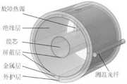
图2是本发明实施例中电缆电磁场及温度场耦合模型;Fig. 2 is the coupling model of cable electromagnetic field and temperature field in the embodiment of the present invention;
图3(a)-3(d)是本发明实施例中的潜隐故障电流量与温度量特征,其中图3(a) 为故障电压与电流,图3(b)为电弧电流及功率,图3(c)为负荷发热温度分布, 图3(d)为故障发热温度分布;Figures 3(a)-3(d) are the characteristics of the latent fault current and temperature in the embodiment of the present invention, wherein Figure 3(a) is the fault voltage and current, Figure 3(b) is the arc current and power, Figure 3(c) is the load heating temperature distribution, and Figure 3(d) is the fault heating temperature distribution;
图4是本发明实施例中不同故障条件下的识别结果;Fig. 4 is the identification result under different fault conditions in the embodiment of the present invention;
图5是本发明实施例中不同线路长度对差动电流的影响。FIG. 5 is the influence of different line lengths on the differential current in the embodiment of the present invention.
具体实施方式Detailed ways
下面结合附图,对实施例作详细说明。The embodiments are described in detail below with reference to the accompanying drawings.
为了解决上述问题,本发明提出了一种基于电流与温度量综合特征的直流 线路潜隐故障判别方法。In order to solve the above problems, the present invention proposes a method for judging latent faults of DC lines based on the comprehensive characteristics of current and temperature.
在柔性直流汇集的新能源发电单元每条送出电缆线路两端分别安装电流互 感器与分布式测温光纤测温设备,由于分布式光纤测温设备所用的光纤就是普 通的通信光纤,因此差动电流数据也可通过该光纤传输。利用故障后40s内的线 路差动电流数据与沿线温度数据,基于电缆温度空间分布规律,对暂态温升波 形特征进行辨识,反解出故障发热功率以及故障径向发生位置,构成二维故障 判据。通过比较各线路判据运算值与整定值之间的大小关系来识别故障并定位 故障区段。Current transformers and distributed temperature measurement optical fiber temperature measurement equipment are installed at both ends of each outgoing cable line of the flexible DC-collected new energy power generation unit. Since the optical fibers used in the distributed optical fiber temperature measurement equipment are ordinary communication Current data can also be transmitted through this fiber. Using the line differential current data and the temperature data along the line within 40s after the fault, based on the spatial distribution law of cable temperature, the characteristics of the transient temperature rise waveform are identified, and the fault heating power and the fault radial position are reversely solved to form a two-dimensional fault. Criterion. Identify the fault and locate the fault section by comparing the magnitude relationship between the operation value of each line criterion and the setting value.
直流线路在发生潜隐故障时,故障存在伴随电弧,此处采用Kizilcay电弧模 型,其电弧电导的表达式为:When a latent fault occurs in the DC line, the fault has an accompanying arc. Here, the Kizilcay arc model is used, and the expression of the arc conductance is:

式中,τ、u0和r0分别为电弧时间常数、电弧特征电压和特征电阻。根据地下电 缆故障实验数据,τ取0.2~0.4ms,u0取300~4000V,r0取0.005~0.015Ω。if为故 障支路电流;garc为电弧电导。In the formula, τ, u0 and r0 are the arc time constant, arc characteristic voltage and characteristic resistance, respectively. According to the experimental data of underground cable fault, τ is 0.2~0.4ms, u0 is 300~4000V, and r0 is 0.005~0.015Ω. if is the fault branch current; garc is the arc conductance.
其潜隐故障的发热功率表达式为:The heating power expression of its latent fault is:

式中,Rc为等效绝缘电阻,表征了线路的剩余绝缘能力;ΔI为差动电流;U为 MMC侧极间电压;u0的含义参见式(1);Qf为故障电弧的热功率。In the formula, Rc is the equivalent insulation resistance, which represents the residual insulation capacity of the line; ΔI is the differential current; U is the voltage between the electrodes on the MMC side; the meaning of u0is shown in formula (1); power.
从而得到电缆故障点的暂态温度径向分布解析式为:Thus, the analytical formula for the radial distribution of transient temperature at the fault point of the cable is obtained as:

其中,in,

式中,Tf为所测温度数据;

不同故障条件下,故障发热功率可达几十至上百W,温度特征以秒级时间 尺度变化。而正常运行下的电缆负荷发热通常远小于1W/m,工作温度变化时间 尺度在小时级甚至天级。因此,潜隐故障存在较为明显的发热特征。Under different fault conditions, the fault heating power can reach tens to hundreds of W, and the temperature characteristics change on a second-level time scale. In normal operation, the load heating of the cable is usually much less than 1W/m, and the time scale of working temperature changes is at the hour level or even the day level. Therefore, latent faults have obvious heating characteristics.
利用线路故障前后故障点处的温度差异,构造综合了电流与温度信息的二 维故障保护判据,基于故障暂态温度分布解析式


式中,F(X)为最小二乘法里的目标函数;tk为设备的计时器输出时间,该时间以早期故障发生时刻为零时刻;Tm为时刻tk所采集到的线路温度数据;Tf通过式 (3)计算所得;Qf和

式中,(u0.min,u0.max)为上面所述电弧模型参数的取值范围(0.3,4)kV;kp.min和kp.max分别为初值选取范围的下限及上限可靠系数,分别取<1和>1的值。根据计算结 果,构造基于电流量与温度量综合特征的直流线路潜隐故障识别判据,其公式 为:In the formula, (u0.min , u0.max ) is the value range (0.3, 4)kV of the arc model parameters described above; kp.min and kp.max are the lower limit of the initial value selection range and The upper limit reliability coefficient, which takes values of <1 and >1, respectively. According to the calculation results, the identification criteria for latent faults of DC lines based on the comprehensive characteristics of current and temperature are constructed, and the formula is as follows:

式中,


故障判据本质上是通过判断暂态温升波形特征区分故障与扰动,当检测到 温度短时快速变化,且波形特征符合理论波形时,即认为故障点发热现象严重。 当P2=0时,判断为扰动;当P2=1时,判断为绝缘缺陷;当P2=2时,判断为 潜隐故障。The fault criterion is essentially to distinguish faults and disturbances by judging the transient temperature rise waveform characteristics. When it is detected that the temperature changes rapidly in a short time, and the waveform characteristics conform to the theoretical waveform, it is considered that the heating phenomenon at the fault point is serious. When P2 =0, it is judged as disturbance; when P2 =1, it is judged as insulation defect; when P2 =2, it is judged as latent fault.
故障径向位置


故障发热功率Qf存在三个整定值Qset3、Qset2、Qset1。其中,前两个整定值 Qset2、Qset1需根据潜隐故障定义原则整定。潜隐故障的定义如下:The fault heating power Qf has three setting values Qset3 , Qset2 and Qset1 . Among them, the first two setting values Qset2 and Qset1 need to be set according to the principle of latent fault definition. Latent faults are defined as follows:
正常运行下,电缆绝缘能力主要来自绝缘层与外护层。等效绝缘电阻可写为 Rc=R绝缘+R护套。各层材料电阻值计算方式为:Under normal operation, the insulation capacity of the cable mainly comes from the insulation layer and the outer sheath. The equivalent insulation resistance can be written as Rc = Rinsulation + Rsheath . The calculation method of the resistance value of each layer material is:

式中,ρi为第i层材料的体积电阻率,单位为Ω·m。通常外护层采用PVC绝 缘材料,体积电阻率在1011Ω·m以上,而绝缘层采用交联聚乙烯(XLPE),体积 电阻率在1014Ω·m以上。为线路长度,单位为m,D、d分别为电缆第i层结 构的外径、内径。In the formula, ρi is the volume resistivity of the i-th layer material, and the unit is Ω·m. Usually the outer sheath is made of PVC insulating material, and the volume resistivity is above 1011 Ω·m, while the insulating layer is made of cross-linked polyethylene (XLPE), and the volume resistivity is above 1014 Ω·m. is the line length, the unit is m, and D and d are the outer diameter and inner diameter of the i-th layer structure of the cable, respectively.
当等效绝缘电阻下降至时Rc=R护套,说明等效来看,电缆绝缘层电阻已降至 0。此时可以认为,故障点起主绝缘作用的电缆结构已被完全击穿,只剩外护套 在维持线路绝缘,故此时的绝缘损伤已无法看作绝缘缺陷。因此,可以得到界 定潜隐故障与绝缘缺陷的边界:When the equivalent insulation resistance drops to Rc =Rsheath , it means that the cable insulation resistance has dropped to 0. At this time, it can be considered that the cable structure that acts as the main insulation at the fault point has been completely broken down, and only the outer sheath is left to maintain the line insulation, so the insulation damage at this time can no longer be regarded as an insulation defect. Therefore, the boundary defining latent faults and insulation defects can be obtained:
Rc.set1=R护套 (7)Rc.set1 = Rsheath (7)
当电树通道完全贯穿电缆时,缆芯经空气与另一极相连,此时将产生缓慢生 长的等离子流注通道,流注通道导电性能良好,致使两极间距不断缩短,极间 等效绝缘电阻Rc也相应减小,当两极间距缩短至气体临界击穿距离时,气体将 瞬间被击穿成为良导体,形成短路。该理论很好地对应了图3的瞬间击穿现象。 因此,边界Rc.set2应取临界击穿距离下的气体等效绝缘电阻。而气体的临界击穿 距离与电压有如下经验公式:When the electrical tree channel completely penetrates the cable, the cable core is connected to the other pole through the air, and a slow-growing plasma streamer channel will be generated. Rc is also reduced accordingly. When the distance between the two poles is shortened to the critical breakdown distance of the gas, the gas will be instantly broken down into a good conductor, forming a short circuit. This theory corresponds well to the instantaneous breakdown phenomenon of Figure 3. Therefore, the boundary Rc.set2 should take the gas equivalent insulation resistance under the critical breakdown distance. The critical breakdown distance and voltage of gas have the following empirical formula:

式中,Ub为临界击穿电压;δ为间隙气压;df为临界击穿距离。该式也可近似简 化为df=30kV/cm。In the formula, Ub is the critical breakdown voltage; δ is the gap pressure; df is the critical breakdown distance. This formula can also be approximately simplified to df =30kV/cm.
在实验的基础上得到电树通道内的气体等效电阻率rair可取106Ω/m左右,将 该值代入式(4),即可得到潜隐故障与短路的边界Rc.set2表达式:On the basis of the experiment, it is obtained that the gas equivalent resistivity rair in the electrical tree channel can be about 106 Ω/m. Substitute this value into equation (4), and the boundary Rc.set2 of latent fault and short circuit can be obtained. Mode:
Rc.set2=rairdf (9)Rc.set2 =rair df (9)
将潜隐故障与绝缘缺陷、短路故障的界定边界Rc.set1与Rc.set2代入,同样引 入可靠系数kr,可整定为:Substitute the boundaries Rc.set1 and Rc.set2 of latent faults, insulation defects and short-circuit faults, and also introduce the reliability coefficient kr , which can be set as:

Qcal的第三个整定值Qset3是区分绝缘缺陷与扰动的边界。当Qcal<Qset3时, 即认为此时发热功率属于环境温度波动所致,判断为系统扰动。因此,整定值 Qset3需躲过温度波动噪声ΔT带来的影响。而在工程上,影响电缆沿线温度的环 境因素可分为两类:环境热源以及环境噪声。The third setting of Qcal , Qset3 , is the boundary between insulation defects and disturbances. When Qcal <Qset3 , it is considered that the heating power at this time is caused by the fluctuation of the ambient temperature, and it is judged as a system disturbance. Therefore, the setting value Qset3 needs to avoid the influence of the temperature fluctuation noise ΔT. In engineering, the environmental factors that affect the temperature along the cable can be divided into two categories: environmental heat source and environmental noise.
其中环境热源主要包括高温管道、太阳照射等因素。然而根据大量电缆运 行温度数据可知,环境热源带来的温度变化极慢,时间尺度长达小时级甚至天 级,而本发明仅采集40s内温度变化波形,故可忽略环境热源影响。Among them, the environmental heat sources mainly include high temperature pipes, sunlight and other factors. However, according to a large number of cable operating temperature data, the temperature change caused by the environmental heat source is extremely slow, and the time scale is as long as hours or even days. The present invention only collects the temperature change waveform within 40s, so the influence of the environmental heat source can be ignored.
环境噪声影响主要来自于量测误差ΔTm与环境温度波动ΔTe。现有分布式光 纤测温设备的测量误差ΔTm在±0.5℃以内;环境温度波动误差需根据现场情况确 定,通常,ΔTe取±0.5℃足以满足要求。综上,可得最大温度噪声为: ΔT=ΔTm+ΔTe=±1℃。设置ΔT大小的温度噪声代入式(4)重复计算m次,反解出 温度噪声下的最大计算功率值Qcal.m,同样引入上面的可靠系数kr>1,即可得整 定值Qset3为:The influence of environmental noise mainly comes from the measurement error ΔTm and the ambient temperature fluctuation ΔTe . The measurement error ΔTm of the existing distributed optical fiber temperature measurement equipment is within ±0.5°C; the ambient temperature fluctuation error needs to be determined according to the site conditions. Usually, ΔTe is ±0.5°C is sufficient to meet the requirements. To sum up, the maximum temperature noise can be obtained as: ΔT=ΔTm +ΔTe =±1°C. Substitute the temperature noise of ΔT into formula (4) and repeat the calculation m times, inversely solve the maximum calculated power value Qcal.m under the temperature noise, and also introduce the above reliability coefficient kr >1 to obtain the set value Qset3 for:

直流汇集母线处综合保护装置分别对各条汇集支路进行故障判断,故障判 据本质上是通过判断暂态温升波形特征区分故障与扰动,当检测到温度短时快 速变化,且波形特征符合理论波形时,即认为故障点发热现象严重。当P2=0时, 判断为扰动;当P2=1时,判断为绝缘缺陷;当P2=2时,判断为潜隐故障。由 于潜隐故障热特性只在故障点附近较为明显,因此所提方法在可靠识别故障的 同时,也定位了故障区段,不需要额外的区段定位算法。The comprehensive protection device at the DC collecting busbar separately judges the faults of each collecting branch. The fault criterion is essentially to distinguish the fault and disturbance by judging the waveform characteristics of the transient temperature rise. When the detected temperature is short, it changes rapidly, and the waveform characteristics match When the theoretical waveform is used, it is considered that the heating phenomenon at the fault point is serious. When P2 =0, it is judged as disturbance; when P2 =1, it is judged as insulation defect; when P2 =2, it is judged as latent fault. Since the thermal characteristics of latent faults are only obvious near the fault point, the proposed method can locate the fault section while reliably identifying the fault, and no additional section locating algorithm is needed.
下面通过具体的实施例来说明本发明方法的优势。本发明中分别搭建新能 源柔直汇集送出系统仿真模型以及电缆电磁场与温度场耦合模型。The advantages of the method of the present invention are illustrated below by specific examples. In the present invention, the simulation model of the new energy flexible direct collection and delivery system and the coupling model of the electromagnetic field and the temperature field of the cable are respectively built.
以两个新能源发电单元为例,搭建新能源直流汇集送出系统。电源容量分 别为1.5MW和1MW;汇集支路长度均为2km;DCT开关频率为3.2kHz,仿真 步长为50μs,采样频率为20kHz,数据窗长为0.2s,正负极电缆间距30mm。如 图1所示。Take two new energy power generation units as an example to build a new energy DC collection and delivery system. The power supply capacity is 1.5MW and 1MW respectively; the length of the collecting branch is 2km; the DCT switching frequency is 3.2kHz, the simulation step size is 50μs, the sampling frequency is 20kHz, the data window length is 0.2s, and the distance between the positive and negative cables is 30mm. As shown in Figure 1.
如图2所示,以云南干塘子光伏直流升压汇集系统示范工程中的电缆型号 为例,在COMSOL搭建YJV22-26/35kV型500mm2标称截面单芯电缆电磁场与 温度场耦合模型。其中,潜隐故障热源设置于电缆正上方,为一细长柱体,测 温光纤紧贴于电缆表面。缆芯中设置流过负荷电流,电流大小根据新能源柔直 汇集送出系统仿真数据设定,可仿真电缆的正常负荷发热过程。电缆周围环境 温度设置为23.6℃。As shown in Figure 2, taking the cable model in the demonstration project of Yunnan Gantangzi photovoltaic DC boost collection system as an example, the coupling model of electromagnetic field and temperature field of YJV22-26/35kV type 500mm2 nominal cross-section single-core cable is built in COMSOL. Among them, the latent fault heat source is set directly above the cable, which is a slender cylinder, and the temperature measuring fiber is close to the surface of the cable. The load current is set in the cable core, and the current size is set according to the simulation data of the new energy flexible direct collection and sending system, which can simulate the normal load heating process of the cable. The ambient temperature around the cable is set to 23.6°C.
将线路长度、极间距、以及电缆参数分别代入式(7)和式(10)中所给出的潜隐 故障定义标准,计算得到该电缆型号下的潜隐故障边界整定值Rset1=73.0kΩ;故 障分类整定值θthr=0.838。Substitute the line length, pole spacing, and cable parameters into the latent fault definition standards given in equations (7) and (10), respectively, and calculate the latent fault boundary setting value Rset1 = 73.0kΩ under the cable model ; Fault classification setting value θthr = 0.838.
以汇集支路1发生潜隐故障为例。设置等效绝缘电阻值为73kΩ;电弧模型 参数u0及r0分别为1.0及0.015。经电路模型与多物理场模型仿真得到故障电压、 故障电流、故障发热功率以及故障点温度空间分布特征如图3所示。Take the latent failure of the
从图3(a)、3(b)中可以看出,汇集电压和线路电流在故障前后变化极其微弱, 电弧电流不到线路电流的2%,与正常负荷波动类似;图3(b)给出了潜隐故障下 电弧电流以及电弧发热功率,可以看出,故障后在电弧电流不大的情况下,电 弧发热达到了40.7W,发热特征明显。It can be seen from Figures 3(a) and 3(b) that the change of the sink voltage and line current is extremely weak before and after the fault, and the arc current is less than 2% of the line current, which is similar to the normal load fluctuation; Figure 3(b) gives From the arc current and arc heating power under the latent fault, it can be seen that the arc heating reaches 40.7W when the arc current is not large after the fault, and the heating characteristics are obvious.
将上述仿真结果(负荷电流17.6A、故障热功率40.7W)作为条件代入电缆多 物理场模型,仿真得到故障前后电缆的温度分布特征。图3(c)给出了正常运行 下电缆的温度分布。经计算,电缆缆芯负荷发热仅为0.15W,可以看出,电缆 工作温度与环境温度相差不大,且分布均匀。图3(d)给出了故障后30s时故障 点温度分布规律,可以看出明显的不均匀分布特征,与上面的理论分析相吻合。The above simulation results (load current 17.6A, fault thermal power 40.7W) are substituted into the cable multiphysics model as conditions, and the temperature distribution characteristics of the cable before and after the fault are obtained by simulation. Figure 3(c) shows the temperature distribution of the cable under normal operation. After calculation, the load heating of the cable core is only 0.15W. It can be seen that the working temperature of the cable is not much different from the ambient temperature, and the distribution is uniform. Figure 3(d) shows the temperature distribution law of the fault point at 30s after the fault. It can be seen that the obvious uneven distribution characteristics are consistent with the above theoretical analysis.
为了验证本发明所提出的一种基于电流量及温度量综合判据的潜隐故障识 别方法,采集模型中前40s内暂态温度数据以及差动电流数据,代入式(4)中, 反解出故障发热功率及故障径向位置

同时,根据电弧热功率表达式可知,故障发热功率大小主要取决于电弧特 征电压u0及等效绝缘电阻值Rc。因此,对不同故障条件(Rc,u0)下的潜隐故障进 行故障电流量及温度量特性的仿真;同时,针对不同故障径向位置
图5中给出了六种不同(Rc,u0)条件下的故障判别结果,每种故障条件分别对 19个径向故障发生位置进行判别,并且还对区外故障时的温度噪声进行了验证。 可以看出,故障综合特征参数的辨识效果较好,误差均可保持在10%以内,且 对区外温度噪声也有较好的抵抗能力较强。Fig. 5 shows the fault discrimination results under six different (Rc , u0 ) conditions, each fault condition discriminates 19 radial fault occurrence positions, and the temperature noise during out-of-area faults is also judged. verified. It can be seen that the identification effect of the comprehensive characteristic parameters of the fault is good, the error can be kept within 10%, and it has a good resistance to the temperature noise outside the area.
表1不同故障条件下的识别结果Table 1 Identification results under different fault conditions

表1给出了更多故障条件下所提故障处理方法的效果验证。所提方法可以 准确辨识故障发热功率Qf以及径向故障位置
本发明所提出的一种基于故障发热特征的识别方法可耐受绝大多数传统电 气量影响因素(新能源出力变化、换流器闭锁、系统噪声)。因此,对长线路场景、 环境温度影响以及故障动态演化三方面影响因素来验证所提方法性能。The identification method based on the fault heating characteristics proposed by the present invention can withstand most of the traditional electric quantity influencing factors (the output change of new energy, the blocking of the converter, the system noise). Therefore, the performance of the proposed method is verified by three factors affecting the long line scenario, the influence of ambient temperature and the dynamic evolution of faults.
长线路场景影响Impact of Long Line Scenarios
根据前文可知,差动电流信息用于计算故障发热功率的迭代初值。因此需 考虑远海、远陆新能源汇集送出长线路上分布电容对差动电流值的影响。It can be seen from the foregoing that the differential current information is used to calculate the initial iterative value of the fault heating power. Therefore, it is necessary to consider the influence of the distributed capacitance on the differential current value on the long line of new energy collection and transmission in the far sea and the far land.
以汇集支路1发生Rc=73.0kΩ的潜隐故障为例,图5给出了汇集支路长度分 别为10、50、125、250及500km下因分布式电容导致的正常运行下的残余差动 电流值ΔIrest。Taking the latent fault of Rc = 73.0kΩ in the collecting
从图中可以看出,稳态残余差动电流值随线路长度而增长,且几乎保持为 一个定值。由于新能源侧DCT固有开关频率带来的高频电压分量在汇集支路对 地电容以及极间电容上产生高频电流,因此长线路上所测差动电流值会略大于 短线路。此外,由于线路电感与电容谐振放大DCT固有频率纹波,因此线路长 度越长,所测差动电流值的波动越大。It can be seen from the figure that the steady-state residual differential current value increases with the line length and remains almost a constant value. Since the high-frequency voltage component brought by the natural switching frequency of the DCT on the new energy side generates high-frequency current on the ground capacitance and the inter-pole capacitance of the collecting branch, the differential current value measured on the long line will be slightly larger than that on the short line. In addition, since the line inductance and capacitance resonate to amplify the DCT natural frequency ripple, the longer the line length, the greater the fluctuation of the measured differential current value.
上述影响的破解思路为:对于差动电流稳态值增大现象,可在工程上设置 分布电容电路补偿值避免该影响;对于差动电流波动增大现象,可通过连续采 集一段时间内的差动电流值并取均值的方法,滤去高频纹波。采集时间可根据 DCT开关频率设置,通常取0.05s即可,该延时远小于40s的本发明方法检测时 间,不会对本发明方法产生影响。The idea of deciphering the above effects is: for the increase of the steady-state value of the differential current, the compensation value of the distributed capacitance circuit can be set in the project to avoid the effect; for the increase of the fluctuation of the differential current, the difference between the The method of moving current value and taking the average value to filter out high frequency ripple. The acquisition time can be set according to the DCT switching frequency, usually 0.05s, the delay is far less than the detection time of the method of the present invention of 40s, and will not affect the method of the present invention.
环境因素影响environmental factors
为充分考虑环境因素带来的温度波动,根据上面对温度噪声来源及大小的 分析,给定温度噪声波动为±1℃/s和±2℃/s。将纯温度噪声波形以及故障温度与 噪声叠加后的波形分别代入所提方法进行验证,得到如表2及表3所示的验证 结果。In order to fully consider the temperature fluctuations caused by environmental factors, according to the above analysis of the source and size of temperature noise, the given temperature noise fluctuations are ±1°C/s and ±2°C/s. The pure temperature noise waveform and the waveform after the superposition of fault temperature and noise are respectively substituted into the proposed method for verification, and the verification results shown in Table 2 and Table 3 are obtained.
表2纯环境温度噪声的影响Table 2 Effects of pure ambient temperature noise


表2给出了单纯对温度噪声波动的识别结果。可以看出,在比较极端的温 度噪声扰动下,所提方法均不会误判。Table 2 shows the identification results of pure temperature noise fluctuations. It can be seen that under the extreme temperature noise disturbance, the proposed method will not misjudge.
表3环境噪声叠加故障温升的影响Table 3 Effect of environmental noise superimposed on fault temperature rise

表3给出了叠加±1℃温度噪声的故障温度特征识别结果,可以看出所提方 法在有噪声叠加下依然可准确反解出故障发热功率以及故障径向位置,最大解 析误差均在7%以内。Table 3 shows the fault temperature feature identification results with superimposed ±1°C temperature noise. It can be seen that the proposed method can still accurately inversely solve the fault heating power and fault radial position under the noise superposition, and the maximum analytical error is 7 % or less.
此外,温度量测还需考虑环境干扰热源对温度量测的影响。上面已论证了 所提方法对干扰热源的耐受能力:由于干扰热源带来的温度变化极其缓慢,时 间尺度在小时级,而本发明采集40s内的暂态温升波形特征来识别故障,因此干 扰热源并不会影响所提方法的可靠性。In addition, the temperature measurement also needs to consider the influence of the environmental interference heat source on the temperature measurement. The tolerance of the proposed method to the interference heat source has been demonstrated above: because the temperature change caused by the interference heat source is extremely slow, and the time scale is at the hour level, and the present invention collects the transient temperature rise waveform characteristics within 40s to identify the fault, so Interfering with the heat source does not affect the reliability of the proposed method.
综上,所提方法有较好的耐受环境温度波动与干扰热源的能力。所提原理 可在温度上升早期检测发热特征,从而避免因温度变化速度慢、空间分布不均 匀、以及故障径向发生位置随机导致的检测时间过长问题。In summary, the proposed method has a good ability to withstand ambient temperature fluctuations and interfere with heat sources. The proposed principle can detect the heating characteristics in the early stage of temperature rise, so as to avoid the problem of long detection time caused by slow temperature change, uneven spatial distribution, and random radial fault locations.
故障动态演化的影响The influence of fault dynamic evolution
由于潜隐故障实际上是一个持续的动态演化过程,等效绝缘电阻近似线性下 降,故障发热功率将近似线性上升,因此,本节通过设定动态变化的等效绝缘 电阻来验证所提方法对故障动态演化的适用性。Since the latent fault is actually a continuous dynamic evolution process, the equivalent insulation resistance decreases approximately linearly, and the fault heating power will increase approximately linearly. Therefore, in this section, the dynamic equivalent insulation resistance is set to verify that the proposed method is suitable for Applicability of fault dynamic evolution.
设置故障参数,令等效绝缘电阻的变化分别为150→110欧、40→25欧、25 →10欧,验证故障判别结果在表4中给出。Set the fault parameters so that the equivalent insulation resistance changes are 150→110 ohms, 40→25 ohms, and 25→10 ohms, respectively.
表4故障动态演化的影响Table 4 Influence of fault dynamic evolution

表4中,Qf.av为故障发热功率的算术均值。从验证结果可知,对于动态变化 的故障发热功率,所提方法计算功率值为实际功率的算术均值,计算误差均可 保持在8%以内,故障径向位置计算误差也保持在7%以内,具有较好的适用性。In Table 4, Qf.av is the arithmetic mean of the fault heating power. It can be seen from the verification results that for the dynamically changing fault heating power, the calculated power value of the proposed method is the arithmetic mean of the actual power, the calculation error can be kept within 8%, and the calculation error of the fault radial position is also kept within 7%. better applicability.
此实施例仅为本发明较佳的具体实施方式,但本发明的保护范围并不局限 于此,任何熟悉本技术领域的技术人员在本发明揭露的技术范围内,可轻易想 到的变化或替换,都应涵盖在本发明的保护范围之内。因此,本发明的保护范 围应该以权利要求的保护范围为准。This embodiment is only a preferred embodiment of the present invention, but the protection scope of the present invention is not limited to this. Any person skilled in the art can easily think of changes or substitutions within the technical scope disclosed by the present invention. , all should be covered within the protection scope of the present invention. Therefore, the protection scope of the present invention should be subject to the protection scope of the claims.
Claims (5)


Priority Applications (1)
| Application Number | Priority Date | Filing Date | Title |
|---|---|---|---|
| CN202210602324.7ACN114935705B (en) | 2022-05-30 | 2022-05-30 | A method for identifying latent faults in DC lines based on comprehensive characteristics of current and temperature |
Applications Claiming Priority (1)
| Application Number | Priority Date | Filing Date | Title |
|---|---|---|---|
| CN202210602324.7ACN114935705B (en) | 2022-05-30 | 2022-05-30 | A method for identifying latent faults in DC lines based on comprehensive characteristics of current and temperature |
Publications (2)
| Publication Number | Publication Date |
|---|---|
| CN114935705Atrue CN114935705A (en) | 2022-08-23 |
| CN114935705B CN114935705B (en) | 2024-10-22 |
Family
ID=82866998
Family Applications (1)
| Application Number | Title | Priority Date | Filing Date |
|---|---|---|---|
| CN202210602324.7AActiveCN114935705B (en) | 2022-05-30 | 2022-05-30 | A method for identifying latent faults in DC lines based on comprehensive characteristics of current and temperature |
Country Status (1)
| Country | Link |
|---|---|
| CN (1) | CN114935705B (en) |
Cited By (1)
| Publication number | Priority date | Publication date | Assignee | Title |
|---|---|---|---|---|
| CN117332740A (en)* | 2023-12-01 | 2024-01-02 | 武汉氢能与燃料电池产业技术研究院有限公司 | Fuel cell system insulation design method and device and electronic equipment |
Citations (6)
| Publication number | Priority date | Publication date | Assignee | Title |
|---|---|---|---|---|
| CN103728539A (en)* | 2014-01-23 | 2014-04-16 | 华北电力大学(保定) | Distributive optical fiber temperature measurement based cable electrical failure simulation analysis method |
| WO2014200375A1 (en)* | 2013-06-09 | 2014-12-18 | Active Space Technologies, Actividades Aeroespaciais, Lda. | Method and system for monitoring electrical wire aging |
| CN110489929A (en)* | 2019-09-06 | 2019-11-22 | 中国南方电网有限责任公司超高压输电公司南宁局 | The simulation model and modeling and simulation method of air-core shunt reactor turn-to-turn fault |
| CN113241737A (en)* | 2021-04-25 | 2021-08-10 | 华北电力大学 | Independent micro-grid protection method based on current temperature mapping |
| CN113567810A (en)* | 2021-07-30 | 2021-10-29 | 中国矿业大学 | A method, device and system for locating arc ground fault section in distribution network |
| CN114417648A (en)* | 2021-11-26 | 2022-04-29 | 广东电网有限责任公司广州供电局 | Method for calculating impact overpressure generated by explosion of cable joint |
- 2022
- 2022-05-30CNCN202210602324.7Apatent/CN114935705B/enactiveActive
Patent Citations (6)
| Publication number | Priority date | Publication date | Assignee | Title |
|---|---|---|---|---|
| WO2014200375A1 (en)* | 2013-06-09 | 2014-12-18 | Active Space Technologies, Actividades Aeroespaciais, Lda. | Method and system for monitoring electrical wire aging |
| CN103728539A (en)* | 2014-01-23 | 2014-04-16 | 华北电力大学(保定) | Distributive optical fiber temperature measurement based cable electrical failure simulation analysis method |
| CN110489929A (en)* | 2019-09-06 | 2019-11-22 | 中国南方电网有限责任公司超高压输电公司南宁局 | The simulation model and modeling and simulation method of air-core shunt reactor turn-to-turn fault |
| CN113241737A (en)* | 2021-04-25 | 2021-08-10 | 华北电力大学 | Independent micro-grid protection method based on current temperature mapping |
| CN113567810A (en)* | 2021-07-30 | 2021-10-29 | 中国矿业大学 | A method, device and system for locating arc ground fault section in distribution network |
| CN114417648A (en)* | 2021-11-26 | 2022-04-29 | 广东电网有限责任公司广州供电局 | Method for calculating impact overpressure generated by explosion of cable joint |
Cited By (2)
| Publication number | Priority date | Publication date | Assignee | Title |
|---|---|---|---|---|
| CN117332740A (en)* | 2023-12-01 | 2024-01-02 | 武汉氢能与燃料电池产业技术研究院有限公司 | Fuel cell system insulation design method and device and electronic equipment |
| CN117332740B (en)* | 2023-12-01 | 2024-02-23 | 武汉氢能与燃料电池产业技术研究院有限公司 | Fuel cell system insulation design method and device and electronic equipment |
Also Published As
| Publication number | Publication date |
|---|---|
| CN114935705B (en) | 2024-10-22 |
Similar Documents
| Publication | Publication Date | Title |
|---|---|---|
| Zhang et al. | Model-based general arcing fault detection in medium-voltage distribution lines | |
| Yao et al. | Impact evaluation of series dc arc faults in dc microgrids | |
| CN109917235B (en) | Method for detecting conductivity defect of cable buffer layer | |
| CN104375056B (en) | Substation cable outgoing line fault monitoring method based on voltage and current initial row waves | |
| CN104360226A (en) | Method for monitoring fault of cable outgoing lines of transformer substation on basis of current initial traveling wave polarity | |
| CN102879704B (en) | Multiparameter data fusion detection method for high resistance ground faults of high-voltage transmission line | |
| CN103901318B (en) | The method of positioning both ground failure and insulation degraded condition in energy conversion system | |
| Hu et al. | Power cable fired by transient arcing below the action value of relay protection: An analysis of a medium-voltage cable joint breakdown fault | |
| CN219715710U (en) | An online monitoring device for high-voltage cable sheath grounding current | |
| CN110658432B (en) | A method for evaluating the moisture level of cable terminals in distribution network | |
| CN114935705B (en) | A method for identifying latent faults in DC lines based on comprehensive characteristics of current and temperature | |
| CN111025096B (en) | XLPE cable aging state evaluation method based on leakage current characteristic factor | |
| CN107942204B (en) | Comprehensive protection method and device for direct current collecting cable | |
| Bayramoğlu et al. | The development of lightning protection and grounding systems: A survey | |
| Tag et al. | A study on the impact of thermal stresses and voids on the partial discharge inception voltage in hvdc power cables | |
| Zhao et al. | Evolution of grounding failure‐insulation failure of 10 kV cable joints: Prerequisites of an explosion in enclosed cable trench | |
| CN110829613B (en) | Method for Harvesting Energy from Ground Wire of Overhead Transmission Line | |
| CN110581566B (en) | Method and device for evaluating accessible capacity of distributed photovoltaic power supply | |
| CN112904232A (en) | Ground fault positioning method and device based on active component of ground wire current | |
| Wang et al. | Real-time calculation of transient ampacity of trench laying cables based on the thermal circuit model and the temperature measurement | |
| CN116859292A (en) | Insulating layer flaw detection device, method and equipment based on leakage current of cable insulating layer | |
| Liu et al. | Analysis of a flux-coupling type superconductor fault current limiter with pancake coils | |
| Gao et al. | New pilot protection method based on the current fault component waveform similarity | |
| Yang et al. | Improving the polarisation and depolarisation current measuring method to avoid ground wire interference | |
| Xu et al. | A Review of DC Arc Fault Diagnosis in Photovoltaic Inverter Systems |
Legal Events
| Date | Code | Title | Description |
|---|---|---|---|
| PB01 | Publication | ||
| PB01 | Publication | ||
| SE01 | Entry into force of request for substantive examination | ||
| SE01 | Entry into force of request for substantive examination | ||
| GR01 | Patent grant | ||
| GR01 | Patent grant |