CN114935595A - Method for manufacturing micro-needle biosensor - Google Patents
Method for manufacturing micro-needle biosensorDownload PDFInfo
- Publication number
- CN114935595A CN114935595ACN202210393852.6ACN202210393852ACN114935595ACN 114935595 ACN114935595 ACN 114935595ACN 202210393852 ACN202210393852 ACN 202210393852ACN 114935595 ACN114935595 ACN 114935595A
- Authority
- CN
- China
- Prior art keywords
- microneedle
- sensor substrate
- electrode
- array
- layer
- Prior art date
- Legal status (The legal status is an assumption and is not a legal conclusion. Google has not performed a legal analysis and makes no representation as to the accuracy of the status listed.)
- Granted
Links
- 238000000034methodMethods0.000titleclaimsabstractdescription45
- 238000004519manufacturing processMethods0.000titleclaimsabstractdescription31
- 239000000758substrateSubstances0.000claimsabstractdescription64
- 239000007788liquidSubstances0.000claimsabstractdescription16
- 239000002861polymer materialSubstances0.000claimsabstractdescription12
- 238000001035dryingMethods0.000claimsabstractdescription9
- 238000002347injectionMethods0.000claimsabstractdescription9
- 239000007924injectionSubstances0.000claimsabstractdescription9
- 238000005266castingMethods0.000claimsabstractdescription6
- 229940079593drugDrugs0.000claimsabstractdescription6
- 239000003814drugSubstances0.000claimsabstractdescription6
- 230000000149penetrating effectEffects0.000claimsabstractdescription5
- 239000000463materialSubstances0.000claimsdescription22
- 102000004190EnzymesHuman genes0.000claimsdescription15
- 108090000790EnzymesProteins0.000claimsdescription15
- 239000003153chemical reaction reagentSubstances0.000claimsdescription15
- DCYOBGZUOMKFPA-UHFFFAOYSA-Niron(2+);iron(3+);octadecacyanideChemical compound[Fe+2].[Fe+2].[Fe+2].[Fe+3].[Fe+3].[Fe+3].[Fe+3].N#[C-].N#[C-].N#[C-].N#[C-].N#[C-].N#[C-].N#[C-].N#[C-].N#[C-].N#[C-].N#[C-].N#[C-].N#[C-].N#[C-].N#[C-].N#[C-].N#[C-].N#[C-]DCYOBGZUOMKFPA-UHFFFAOYSA-N0.000claimsdescription15
- 229960003351prussian blueDrugs0.000claimsdescription15
- 239000013225prussian blueSubstances0.000claimsdescription15
- 229920001661ChitosanPolymers0.000claimsdescription10
- 229920000249biocompatible polymerPolymers0.000claimsdescription10
- 239000002184metalSubstances0.000claimsdescription9
- 229910052751metalInorganic materials0.000claimsdescription9
- 239000000560biocompatible materialSubstances0.000claimsdescription5
- 238000001704evaporationMethods0.000claimsdescription5
- 230000008020evaporationEffects0.000claimsdescription5
- 238000004544sputter depositionMethods0.000claimsdescription5
- 238000005192partitionMethods0.000claimsdescription4
- 108010022355FibroinsProteins0.000claimsdescription3
- 239000004433Thermoplastic polyurethaneSubstances0.000claimsdescription3
- 239000004205dimethyl polysiloxaneSubstances0.000claimsdescription3
- 229920000435poly(dimethylsiloxane)Polymers0.000claimsdescription3
- 229920000747poly(lactic acid)Polymers0.000claimsdescription3
- -1polydimethylsiloxanePolymers0.000claimsdescription3
- 239000004626polylactic acidSubstances0.000claimsdescription3
- 229920002803thermoplastic polyurethanePolymers0.000claimsdescription3
- WQZGKKKJIJFFOK-GASJEMHNSA-NGlucoseNatural productsOC[C@H]1OC(O)[C@H](O)[C@@H](O)[C@@H]1OWQZGKKKJIJFFOK-GASJEMHNSA-N0.000description13
- 239000008103glucoseSubstances0.000description13
- 239000000243solutionSubstances0.000description11
- 239000012530fluidSubstances0.000description9
- 238000010586diagramMethods0.000description8
- 238000010438heat treatmentMethods0.000description8
- 230000004888barrier functionEffects0.000description4
- XLYOFNOQVPJJNP-UHFFFAOYSA-NwaterSubstancesOXLYOFNOQVPJJNP-UHFFFAOYSA-N0.000description4
- QTBSBXVTEAMEQO-UHFFFAOYSA-NAcetic acidChemical compoundCC(O)=OQTBSBXVTEAMEQO-UHFFFAOYSA-N0.000description3
- UHOVQNZJYSORNB-UHFFFAOYSA-NBenzeneChemical compoundC1=CC=CC=C1UHOVQNZJYSORNB-UHFFFAOYSA-N0.000description3
- 238000001514detection methodMethods0.000description3
- 238000000465mouldingMethods0.000description3
- URLKBWYHVLBVBO-UHFFFAOYSA-NPara-XyleneChemical groupCC1=CC=C(C)C=C1URLKBWYHVLBVBO-UHFFFAOYSA-N0.000description2
- 229910021607Silver chlorideInorganic materials0.000description2
- 238000011088calibration curveMethods0.000description2
- HKZLPVFGJNLROG-UHFFFAOYSA-Msilver monochlorideChemical compound[Cl-].[Ag+]HKZLPVFGJNLROG-UHFFFAOYSA-M0.000description2
- 230000000087stabilizing effectEffects0.000description2
- CBENFWSGALASAD-UHFFFAOYSA-NOzoneChemical compound[O-][O+]=OCBENFWSGALASAD-UHFFFAOYSA-N0.000description1
- 208000002193PainDiseases0.000description1
- 229910000831SteelInorganic materials0.000description1
- 238000010521absorption reactionMethods0.000description1
- 239000012491analyteSubstances0.000description1
- 238000003491arrayMethods0.000description1
- 230000009286beneficial effectEffects0.000description1
- 230000015572biosynthetic processEffects0.000description1
- 238000006243chemical reactionMethods0.000description1
- 230000005611electricityEffects0.000description1
- 238000009713electroplatingMethods0.000description1
- UQSQSQZYBQSBJZ-UHFFFAOYSA-Nfluorosulfonic acidChemical compoundOS(F)(=O)=OUQSQSQZYBQSBJZ-UHFFFAOYSA-N0.000description1
- 239000006260foamSubstances0.000description1
- 229910052737goldInorganic materials0.000description1
- 230000005660hydrophilic surfaceEffects0.000description1
- 238000011534incubationMethods0.000description1
- 208000015181infectious diseaseDiseases0.000description1
- 239000002198insoluble materialSubstances0.000description1
- 238000002955isolationMethods0.000description1
- 238000003698laser cuttingMethods0.000description1
- 239000011344liquid materialSubstances0.000description1
- 208000004296neuralgiaDiseases0.000description1
- 230000003647oxidationEffects0.000description1
- 238000007254oxidation reactionMethods0.000description1
- 238000000059patterningMethods0.000description1
- 230000035515penetrationEffects0.000description1
- 229910052697platinumInorganic materials0.000description1
- 230000000750progressive effectEffects0.000description1
- 238000006722reduction reactionMethods0.000description1
- 229910001220stainless steelInorganic materials0.000description1
- 239000010935stainless steelSubstances0.000description1
- 239000010959steelSubstances0.000description1
- 238000003756stirringMethods0.000description1
- 238000007920subcutaneous administrationMethods0.000description1
- 239000000126substanceSubstances0.000description1
- 230000008961swellingEffects0.000description1
- RCHUVCPBWWSUMC-UHFFFAOYSA-Ntrichloro(octyl)silaneChemical compoundCCCCCCCC[Si](Cl)(Cl)ClRCHUVCPBWWSUMC-UHFFFAOYSA-N0.000description1
Images


Classifications
- G—PHYSICS
- G01—MEASURING; TESTING
- G01N—INVESTIGATING OR ANALYSING MATERIALS BY DETERMINING THEIR CHEMICAL OR PHYSICAL PROPERTIES
- G01N27/00—Investigating or analysing materials by the use of electric, electrochemical, or magnetic means
- G01N27/26—Investigating or analysing materials by the use of electric, electrochemical, or magnetic means by investigating electrochemical variables; by using electrolysis or electrophoresis
- G01N27/28—Electrolytic cell components
- G01N27/30—Electrodes, e.g. test electrodes; Half-cells
- G01N27/327—Biochemical electrodes, e.g. electrical or mechanical details for in vitro measurements
- A—HUMAN NECESSITIES
- A61—MEDICAL OR VETERINARY SCIENCE; HYGIENE
- A61B—DIAGNOSIS; SURGERY; IDENTIFICATION
- A61B5/00—Measuring for diagnostic purposes; Identification of persons
- A61B5/145—Measuring characteristics of blood in vivo, e.g. gas concentration or pH-value ; Measuring characteristics of body fluids or tissues, e.g. interstitial fluid or cerebral tissue
- A61B5/14503—Measuring characteristics of blood in vivo, e.g. gas concentration or pH-value ; Measuring characteristics of body fluids or tissues, e.g. interstitial fluid or cerebral tissue invasive, e.g. introduced into the body by a catheter or needle or using implanted sensors
- A—HUMAN NECESSITIES
- A61—MEDICAL OR VETERINARY SCIENCE; HYGIENE
- A61B—DIAGNOSIS; SURGERY; IDENTIFICATION
- A61B5/00—Measuring for diagnostic purposes; Identification of persons
- A61B5/145—Measuring characteristics of blood in vivo, e.g. gas concentration or pH-value ; Measuring characteristics of body fluids or tissues, e.g. interstitial fluid or cerebral tissue
- A61B5/14532—Measuring characteristics of blood in vivo, e.g. gas concentration or pH-value ; Measuring characteristics of body fluids or tissues, e.g. interstitial fluid or cerebral tissue for measuring glucose, e.g. by tissue impedance measurement
- A—HUMAN NECESSITIES
- A61—MEDICAL OR VETERINARY SCIENCE; HYGIENE
- A61M—DEVICES FOR INTRODUCING MEDIA INTO, OR ONTO, THE BODY; DEVICES FOR TRANSDUCING BODY MEDIA OR FOR TAKING MEDIA FROM THE BODY; DEVICES FOR PRODUCING OR ENDING SLEEP OR STUPOR
- A61M37/00—Other apparatus for introducing media into the body; Percutany, i.e. introducing medicines into the body by diffusion through the skin
- A61M37/0015—Other apparatus for introducing media into the body; Percutany, i.e. introducing medicines into the body by diffusion through the skin by using microneedles
- G—PHYSICS
- G01—MEASURING; TESTING
- G01N—INVESTIGATING OR ANALYSING MATERIALS BY DETERMINING THEIR CHEMICAL OR PHYSICAL PROPERTIES
- G01N27/00—Investigating or analysing materials by the use of electric, electrochemical, or magnetic means
- G01N27/26—Investigating or analysing materials by the use of electric, electrochemical, or magnetic means by investigating electrochemical variables; by using electrolysis or electrophoresis
- G01N27/28—Electrolytic cell components
- G01N27/30—Electrodes, e.g. test electrodes; Half-cells
- G01N27/327—Biochemical electrodes, e.g. electrical or mechanical details for in vitro measurements
- G01N27/3271—Amperometric enzyme electrodes for analytes in body fluids, e.g. glucose in blood
- G01N27/3272—Test elements therefor, i.e. disposable laminated substrates with electrodes, reagent and channels
- G—PHYSICS
- G01—MEASURING; TESTING
- G01N—INVESTIGATING OR ANALYSING MATERIALS BY DETERMINING THEIR CHEMICAL OR PHYSICAL PROPERTIES
- G01N27/00—Investigating or analysing materials by the use of electric, electrochemical, or magnetic means
- G01N27/26—Investigating or analysing materials by the use of electric, electrochemical, or magnetic means by investigating electrochemical variables; by using electrolysis or electrophoresis
- G01N27/28—Electrolytic cell components
- G01N27/30—Electrodes, e.g. test electrodes; Half-cells
- G01N27/327—Biochemical electrodes, e.g. electrical or mechanical details for in vitro measurements
- G01N27/3275—Sensing specific biomolecules, e.g. nucleic acid strands, based on an electrode surface reaction
- G01N27/3277—Sensing specific biomolecules, e.g. nucleic acid strands, based on an electrode surface reaction being a redox reaction, e.g. detection by cyclic voltammetry
- G—PHYSICS
- G01—MEASURING; TESTING
- G01N—INVESTIGATING OR ANALYSING MATERIALS BY DETERMINING THEIR CHEMICAL OR PHYSICAL PROPERTIES
- G01N27/00—Investigating or analysing materials by the use of electric, electrochemical, or magnetic means
- G01N27/26—Investigating or analysing materials by the use of electric, electrochemical, or magnetic means by investigating electrochemical variables; by using electrolysis or electrophoresis
- G01N27/416—Systems
- G01N27/48—Systems using polarography, i.e. measuring changes in current under a slowly-varying voltage
- A—HUMAN NECESSITIES
- A61—MEDICAL OR VETERINARY SCIENCE; HYGIENE
- A61B—DIAGNOSIS; SURGERY; IDENTIFICATION
- A61B2562/00—Details of sensors; Constructional details of sensor housings or probes; Accessories for sensors
- A61B2562/12—Manufacturing methods specially adapted for producing sensors for in-vivo measurements
- A—HUMAN NECESSITIES
- A61—MEDICAL OR VETERINARY SCIENCE; HYGIENE
- A61M—DEVICES FOR INTRODUCING MEDIA INTO, OR ONTO, THE BODY; DEVICES FOR TRANSDUCING BODY MEDIA OR FOR TAKING MEDIA FROM THE BODY; DEVICES FOR PRODUCING OR ENDING SLEEP OR STUPOR
- A61M37/00—Other apparatus for introducing media into the body; Percutany, i.e. introducing medicines into the body by diffusion through the skin
- A61M37/0015—Other apparatus for introducing media into the body; Percutany, i.e. introducing medicines into the body by diffusion through the skin by using microneedles
- A61M2037/0023—Drug applicators using microneedles
- A—HUMAN NECESSITIES
- A61—MEDICAL OR VETERINARY SCIENCE; HYGIENE
- A61M—DEVICES FOR INTRODUCING MEDIA INTO, OR ONTO, THE BODY; DEVICES FOR TRANSDUCING BODY MEDIA OR FOR TAKING MEDIA FROM THE BODY; DEVICES FOR PRODUCING OR ENDING SLEEP OR STUPOR
- A61M37/00—Other apparatus for introducing media into the body; Percutany, i.e. introducing medicines into the body by diffusion through the skin
- A61M37/0015—Other apparatus for introducing media into the body; Percutany, i.e. introducing medicines into the body by diffusion through the skin by using microneedles
- A61M2037/003—Other apparatus for introducing media into the body; Percutany, i.e. introducing medicines into the body by diffusion through the skin by using microneedles having a lumen
- A—HUMAN NECESSITIES
- A61—MEDICAL OR VETERINARY SCIENCE; HYGIENE
- A61M—DEVICES FOR INTRODUCING MEDIA INTO, OR ONTO, THE BODY; DEVICES FOR TRANSDUCING BODY MEDIA OR FOR TAKING MEDIA FROM THE BODY; DEVICES FOR PRODUCING OR ENDING SLEEP OR STUPOR
- A61M37/00—Other apparatus for introducing media into the body; Percutany, i.e. introducing medicines into the body by diffusion through the skin
- A61M37/0015—Other apparatus for introducing media into the body; Percutany, i.e. introducing medicines into the body by diffusion through the skin by using microneedles
- A61M2037/0046—Solid microneedles
- A—HUMAN NECESSITIES
- A61—MEDICAL OR VETERINARY SCIENCE; HYGIENE
- A61M—DEVICES FOR INTRODUCING MEDIA INTO, OR ONTO, THE BODY; DEVICES FOR TRANSDUCING BODY MEDIA OR FOR TAKING MEDIA FROM THE BODY; DEVICES FOR PRODUCING OR ENDING SLEEP OR STUPOR
- A61M37/00—Other apparatus for introducing media into the body; Percutany, i.e. introducing medicines into the body by diffusion through the skin
- A61M37/0015—Other apparatus for introducing media into the body; Percutany, i.e. introducing medicines into the body by diffusion through the skin by using microneedles
- A61M2037/0053—Methods for producing microneedles
- A—HUMAN NECESSITIES
- A61—MEDICAL OR VETERINARY SCIENCE; HYGIENE
- A61M—DEVICES FOR INTRODUCING MEDIA INTO, OR ONTO, THE BODY; DEVICES FOR TRANSDUCING BODY MEDIA OR FOR TAKING MEDIA FROM THE BODY; DEVICES FOR PRODUCING OR ENDING SLEEP OR STUPOR
- A61M37/00—Other apparatus for introducing media into the body; Percutany, i.e. introducing medicines into the body by diffusion through the skin
- A61M37/0015—Other apparatus for introducing media into the body; Percutany, i.e. introducing medicines into the body by diffusion through the skin by using microneedles
- A61M2037/0061—Methods for using microneedles
Landscapes
- Health & Medical Sciences (AREA)
- Life Sciences & Earth Sciences (AREA)
- Physics & Mathematics (AREA)
- General Health & Medical Sciences (AREA)
- Engineering & Computer Science (AREA)
- Molecular Biology (AREA)
- Chemical & Material Sciences (AREA)
- Pathology (AREA)
- Heart & Thoracic Surgery (AREA)
- Animal Behavior & Ethology (AREA)
- Biomedical Technology (AREA)
- Public Health (AREA)
- Veterinary Medicine (AREA)
- Medical Informatics (AREA)
- Biophysics (AREA)
- Hematology (AREA)
- Optics & Photonics (AREA)
- Surgery (AREA)
- Analytical Chemistry (AREA)
- Biochemistry (AREA)
- General Physics & Mathematics (AREA)
- Immunology (AREA)
- Electrochemistry (AREA)
- Chemical Kinetics & Catalysis (AREA)
- Anesthesiology (AREA)
- Dermatology (AREA)
- Emergency Medicine (AREA)
- Spectroscopy & Molecular Physics (AREA)
- Measurement Of The Respiration, Hearing Ability, Form, And Blood Characteristics Of Living Organisms (AREA)
- Micromachines (AREA)
Abstract
Translated fromChinese
Description
Translated fromChinese技术领域technical field
本申请实施例涉及医疗器械技术领域,具体而言,涉及一种微针生物传感器的制造方法。The embodiments of the present application relate to the technical field of medical devices, and in particular, to a method for manufacturing a microneedle biosensor.
背景技术Background technique
微针阵列生物传感器是在微针阵列的表面沉积一层生物识别分子,当微针阵列生物传感器刺入人体时,微针阵列上的生物识别分子会与组织液中的生物分子进行反应并产生电子,将目标浓度以电信号表示出来。微针阵列生物传感器在进行人体检测时不会碰到皮下的痛觉神经,具有无痛、操作简单与安全无感染等优势。The microneedle array biosensor deposits a layer of biorecognition molecules on the surface of the microneedle array. When the microneedle array biosensor pierces the human body, the biorecognition molecules on the microneedle array will react with the biomolecules in the tissue fluid and generate electrons. , the target concentration is represented by an electrical signal. The microneedle array biosensor does not touch the subcutaneous pain nerve during human body detection, and has the advantages of no pain, simple operation, safety and no infection.
但是,目前的微针传感器在生物可降解或生物兼容性方面的效果不太理想。However, current microneedle sensors are less than ideal in terms of biodegradability or biocompatibility.
发明内容SUMMARY OF THE INVENTION
本申请实施例提供一种微针生物传感器的制造方法,旨在提高微针传感器的生物可降解或生物兼容性能力。The embodiments of the present application provide a method for manufacturing a microneedle biosensor, which aims to improve the biodegradability or biocompatibility of the microneedle sensor.
本申请实施例第一方面提供一种微针生物传感器的制造方法,所述方法包括:A first aspect of the embodiments of the present application provides a method for manufacturing a microneedle biosensor, the method comprising:
提供模具,所述模具上形成有微针阵列图案或微针孔阵列图案;providing a mold on which a microneedle array pattern or a microneedle hole array pattern is formed;
将液态聚合物材料铸造在所述模具上,干燥后脱模,形成传感器基底,所述传感器基底上具有内部中空的空心微针阵列;其中,所述液态聚合物材料为生物可降解材料或生物兼容性材料;Casting the liquid polymer material on the mold, and demolding after drying to form a sensor substrate, the sensor substrate has a hollow microneedle array with an inner hollow; wherein, the liquid polymer material is a biodegradable material or a biological Compatible materials;
穿透所述空心微针阵列中每个微针的尖端;penetrate the tip of each microneedle in the hollow microneedle array;
在所述传感器基底上形成工作电极和电源电极,所述工作电极和所述电源电极分别覆盖一部分的所述空心微针阵列。A working electrode and a power supply electrode are formed on the sensor substrate, and the working electrode and the power supply electrode respectively cover a part of the hollow microneedle array.
可选地,所述液态聚合物材料包括:壳聚糖、聚乳酸、丝素蛋白或热塑性聚氨酯。Optionally, the liquid polymer material includes: chitosan, polylactic acid, silk fibroin or thermoplastic polyurethane.
可选地,在所述传感器基底上形成工作电极和电源电极中,所述方法包括:Optionally, in forming a working electrode and a power supply electrode on the sensor substrate, the method includes:
在所述传感器基底上所述空心微针阵列凸出的一侧形成工作电极和电源电极;A working electrode and a power supply electrode are formed on the protruding side of the hollow microneedle array on the sensor substrate;
或者,在所述传感器基底上所述空心微针阵列内凹的一侧形成工作电极和电源电极。Alternatively, a working electrode and a power supply electrode are formed on the concave side of the hollow microneedle array on the sensor substrate.
可选地,所述工作电极包括层叠设置在所述传感器基底上的电极层、普鲁士蓝层和试剂酶层;在所述传感器基底上形成工作电极之中,所述方法包括:Optionally, the working electrode includes an electrode layer, a Prussian blue layer and a reagent enzyme layer stacked on the sensor substrate; in forming the working electrode on the sensor substrate, the method includes:
通过蒸镀或溅射工艺将电极层形成在所述传感器基底上,以使所述电极层覆盖一部分的所述空心微针阵列;forming an electrode layer on the sensor substrate by an evaporation or sputtering process, so that the electrode layer covers a part of the hollow microneedle array;
在所述电极层远离所述传感器基底的一侧形成普鲁士蓝层;forming a Prussian blue layer on the side of the electrode layer away from the sensor substrate;
在所述普鲁士蓝层远离所述电极层的一侧形成试剂酶层;forming a reagent enzyme layer on the side of the Prussian blue layer away from the electrode layer;
在所述试剂酶层远离所述普鲁士蓝层的一侧形成生物兼容聚合物层。A biocompatible polymer layer is formed on the side of the reagent enzyme layer away from the Prussian blue layer.
可选地,所述工作电极与所述电源电极之间具有隔断区域。在所述传感器基底上形成工作电极和电源电极之前,所述方法还包括:Optionally, there is an isolation region between the working electrode and the power supply electrode. Before forming the working electrode and the power supply electrode on the sensor substrate, the method further includes:
在所述传感器基底上形成隔水层。A water barrier layer is formed on the sensor substrate.
可选地,在穿透所述空心微针阵列中每个微针的尖端中,所述方法包括:Optionally, in penetrating the tip of each microneedle in the hollow microneedle array, the method comprises:
通过金属针阵列穿透所述空心微针阵列中每个微针的尖端,其中,所述金属针阵列的钢针与所述空心微针阵列的微针一一对应。The tip of each microneedle in the hollow microneedle array is penetrated through the metal needle array, wherein the steel needles of the metal needle array correspond one-to-one with the microneedles of the hollow microneedle array.
可选地,所述模具的材料为聚二甲基硅氧烷。Optionally, the material of the mold is polydimethylsiloxane.
本申请实施例第二方面提供一种微针生物传感器的应用,包括如本申请实施例第一方面提供的微针生物传感器的制造方法所制造的微针传感器,所述微针传感器包括传感器基底及形成在传感器基底上的空心微针阵列:A second aspect of the embodiments of the present application provides an application of a microneedle biosensor, including a microneedle sensor manufactured by the method for manufacturing a microneedle biosensor provided in the first aspect of the embodiments of the present application, where the microneedle sensor includes a sensor substrate and a hollow microneedle array formed on the sensor substrate:
将所述空心微针阵列作为注入通道用于药物注射。The hollow microneedle array is used as an injection channel for drug injection.
有益效果:Beneficial effects:
本申请提供一种微针生物传感器的制造方法,通过将液态聚合物材料铸造在具有微针阵列图案或微针孔阵列图案的模具上,在进行干燥后脱模,从而形成具有内部中空的空心微针阵列的传感器基底,再穿透空心微针阵列中每个微针的尖端,同时在传感器基底上形成工作电极和电源电极,如此便完成了微针传感器的制造;通过直接利用模具形成带有空心微针阵列的传感器基底,使得传感器基底的材料可以选择生物可降解材料或生物兼容性材料,从而可以有效提高微针传感器的生物可降解能力或生物兼容性能力。The present application provides a method for manufacturing a microneedle biosensor, by casting a liquid polymer material on a mold with a microneedle array pattern or a microneedle hole array pattern, and demolding after drying, thereby forming a hollow with an inner hollow The sensor substrate of the microneedle array penetrates the tip of each microneedle in the hollow microneedle array, and at the same time forms a working electrode and a power electrode on the sensor substrate, thus completing the fabrication of the microneedle sensor; The sensor substrate with the hollow microneedle array enables the selection of biodegradable materials or biocompatible materials for the material of the sensor substrate, thereby effectively improving the biodegradability or biocompatibility of the microneedle sensor.
附图说明Description of drawings
为了更清楚地说明本申请实施例的技术方案,下面将对本申请实施例的描述中所需要使用的附图作简单地介绍,显而易见地,下面描述中的附图仅仅是本申请的一些实施例,对于本领域普通技术人员来讲,在不付出创造性劳动性的前提下,还可以根据这些附图获得其他的附图。In order to illustrate the technical solutions of the embodiments of the present application more clearly, the following briefly introduces the drawings that are used in the description of the embodiments of the present application. Obviously, the drawings in the following description are only some embodiments of the present application. , for those of ordinary skill in the art, other drawings can also be obtained from these drawings without creative labor.
图1是本申请一实施例提出的一种微针生物传感器的制造方法的步骤流程图;FIG. 1 is a flow chart of steps of a method for manufacturing a microneedle biosensor proposed in an embodiment of the present application;
图2是本申请一实施例提出的一种微针生物传感器的制造方法中模具制造的步骤流程图;FIG. 2 is a flow chart of the steps of mold manufacturing in a method for manufacturing a microneedle biosensor proposed in an embodiment of the present application;
图3是本申请一实施例提出的一种微针生物传感器的制造方法中传感器基底制造的步骤流程图;3 is a flow chart of steps of manufacturing a sensor substrate in a method for manufacturing a microneedle biosensor proposed in an embodiment of the present application;
图4是本申请一实施例提出的一种微针生物传感器的制造方法中工作电极制造的步骤流程图;FIG. 4 is a flow chart of steps of manufacturing a working electrode in a manufacturing method of a microneedle biosensor proposed in an embodiment of the present application;
图5是本申请一实施例提出的一种微针生物传感器一面的电子显微镜扫描图;5 is a scanning electron microscope view of one side of a microneedle biosensor proposed in an embodiment of the present application;
图6是本申请一实施例提出的一种微针生物传感器另一面的电子显微镜扫描图图;6 is an electron microscope scanning diagram of the other side of a microneedle biosensor proposed in an embodiment of the present application;
图7是本申请一实施例提出的一种微针生物传感器的结构示意图;7 is a schematic structural diagram of a microneedle biosensor proposed in an embodiment of the present application;
图8是图7中a-a’剖线的剖面结构示意图;Fig. 8 is the sectional structure schematic diagram of the section line a-a' in Fig. 7;
图9是本申请一实施例提出的另一种微针生物传感器的结构示意图;9 is a schematic structural diagram of another microneedle biosensor proposed in an embodiment of the present application;
图10是图9中b-b’剖线的剖面结构示意图;Fig. 10 is the sectional structure schematic diagram of b-b' section line in Fig. 9;
图11是本申请一实施例提出的另一种微针生物传感器的结构示意图;11 is a schematic structural diagram of another microneedle biosensor proposed in an embodiment of the present application;
图12是本申请一实施例提出的另一种微针生物传感器的结构示意图;12 is a schematic structural diagram of another microneedle biosensor proposed in an embodiment of the present application;
图13是本申请一实施例提出的微针生物传感器在检测不同浓度的模拟组织液中的葡萄糖浓度时,产生的电流随时间变化的曲线图;FIG. 13 is a graph showing the variation of current with time when the microneedle biosensor proposed in an embodiment of the present application detects the glucose concentration in simulated tissue fluid of different concentrations;
图14是本申请一实施例提出的微针生物传感器在检测不同浓度的模拟组织液中的葡萄糖浓度时,产生的电流增幅随葡萄糖浓度大小变化的校准曲线图。FIG. 14 is a calibration curve diagram of the current increase generated by the microneedle biosensor proposed in an embodiment of the present application as a function of the glucose concentration when detecting the glucose concentration in simulated tissue fluid of different concentrations.
附图标记说明:1、传感器基底;2、空心微针阵列;3、工作电极;4、电源电极;41、作用电极;42、参比电极;43、对电极;A、隔断区域。Description of reference numerals: 1. Sensor substrate; 2. Hollow microneedle array; 3. Working electrode; 4. Power electrode; 41. Working electrode; 42. Reference electrode; 43. Counter electrode;
具体实施方式Detailed ways
下面将结合本申请实施例中的附图,对本申请实施例中的技术方案进行清楚、完整地描述,显然,所描述的实施例是本申请一部分实施例,而不是全部的实施例。基于本申请中的实施例,本领域普通技术人员在没有作出创造性劳动前提下所获得的所有其他实施例,都属于本申请保护的范围。The technical solutions in the embodiments of the present application will be clearly and completely described below with reference to the accompanying drawings in the embodiments of the present application. Obviously, the described embodiments are part of the embodiments of the present application, not all of the embodiments. Based on the embodiments in the present application, all other embodiments obtained by those of ordinary skill in the art without creative work fall within the protection scope of the present application.
图1示出了一种微针生物传感器的制造方法的步骤流程图。参照图1所示,本申请提供一种微针生物传感器的制造方法,所述方法包括如下步骤:FIG. 1 shows a flow chart of the steps of a manufacturing method of a microneedle biosensor. Referring to FIG. 1, the present application provides a method for manufacturing a microneedle biosensor. The method includes the following steps:
步骤100:提供模具,模具上形成有微针阵列图案或微针孔阵列图案。Step 100: Provide a mold on which a microneedle array pattern or a microneedle hole array pattern is formed.
具体地,在制作带有微针阵列图案或微针孔阵列图案的模具前,需要先提供具有负图案的成型模板,此处的负图案是指为形成微针阵列图案或微针孔阵列图案而设置的图案。具有负图案的成型模板可以选择购买现有的模板或者利用激光切割机自制。Specifically, before making a mold with a microneedle array pattern or a micropinhole array pattern, it is necessary to provide a forming template with a negative pattern. The negative pattern here refers to the formation of the microneedle array pattern or the micropinhole array pattern. And set the pattern. Forming stencils with negative patterns can choose to buy existing stencils or use a laser cutting machine to make them.
参照图2所示,为本申请实施例公开的一种制作具有微针图案阵列的模具的方法,所述方法包括以下步骤:Referring to FIG. 2 , a method for manufacturing a mold having a microneedle pattern array disclosed in an embodiment of the present application includes the following steps:
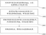
步骤1001:利用紫外臭氧处理成型模板5min,以在成型模板上形成亲水面;Step 1001: Utilize ultraviolet ozone to process the forming template for 5 min to form a hydrophilic surface on the forming template;
步骤1002:利用5%辛基三氯硅烷在苯蒸汽中孵育成型模板16min,孵育温度为60℃,使成型模板的表面硅烷化;Step 1002: use 5% octyltrichlorosilane to incubate the molding template in benzene vapor for 16 min, and the incubation temperature is 60°C to silanize the surface of the molding template;
步骤1003:将制作模具的液态材料倒入改性的成型模板中,并在烘箱内加热2h,加热温度为80℃;Step 1003: Pour the liquid material for making the mold into the modified molding template, and heat it in an oven for 2 hours at a heating temperature of 80°C;
步骤1004:待模具固化后,将模具与成型模板脱离,得到带有微针阵列的模具。Step 1004: After the mold is cured, the mold is separated from the forming template to obtain a mold with a microneedle array.
在具体应用时,模具和成型模板的材料都可以选用聚二甲基硅氧烷,可以降低模具和成形模板的所需成本,从而进一步降低微针生物传感器的制造成本。同时,在上述步骤中,制作模具时所采用的加热温度和加热时间可以根据模具或成型模板的材料进行调整。In specific applications, polydimethylsiloxane can be selected as the material of the mold and the forming template, which can reduce the required cost of the mold and the forming template, thereby further reducing the manufacturing cost of the microneedle biosensor. Meanwhile, in the above steps, the heating temperature and heating time used in making the mold can be adjusted according to the material of the mold or the forming template.
步骤102:将液态聚合物材料铸造在模具上,干燥后脱模,形成传感器基底1,传感器基底1上具有内部中空的空心微针阵列2;其中,液态聚合物材料为生物可降解材料或生物兼容性材料。Step 102 : casting the liquid polymer material on the mold, and demolding after drying to form a
具体地,液态聚合物材料可以为生物可降解材料,如壳聚糖、聚乳酸、丝素蛋白;也可以为生物兼容性材料,如热塑性聚氨酯;在采用生物可降解材料时,使得微针传感器具有可降解能力,在使用后可以自然分解;而采用生物兼容性材料,则使得微针传感器的生物兼容性较强,在使用时可以避免对人体造成损害。Specifically, the liquid polymer material can be a biodegradable material, such as chitosan, polylactic acid, and silk fibroin; it can also be a biocompatible material, such as thermoplastic polyurethane; when a biodegradable material is used, the microneedle sensor can be It is degradable and can be decomposed naturally after use; and the use of biocompatible materials makes the microneedle sensor more biocompatible, and can avoid damage to the human body during use.
参照图3所示,为本申请实施例公开的一种制作壳聚糖材料的传感器基底的方法,所述方法包括如下步骤:Referring to FIG. 3 , a method for manufacturing a sensor substrate of chitosan material disclosed in an embodiment of the present application includes the following steps:
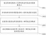
步骤1011:将7%壳聚糖溶解在2%醋酸中,并利用电磁搅拌器搅拌24h,随后利用超声波去除壳聚糖溶液中的泡沫。Step 1011: Dissolve 7% chitosan in 2% acetic acid, stir with an electromagnetic stirrer for 24 hours, and then use ultrasonic waves to remove foam in the chitosan solution.
步骤1012:将壳聚糖溶液注入模具中,同时利用烤箱加热30min,加热温度为60℃。Step 1012: Inject the chitosan solution into the mold, and at the same time, use an oven to heat for 30 minutes, and the heating temperature is 60°C.
步骤1013:在干燥完成后,将形成的壳聚糖材质的传感器基底1与模具脱离。Step 1013: After the drying is completed, the formed
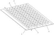
这样,参照图5和图6所示,便形成了具备中空的空心微针阵列2的传感器基底1;其中,参照图7和图9所示,空心微针阵列2的微针的形状可以是棱锥或圆锥。In this way, as shown in FIGS. 5 and 6 , a
同时,在选用其他材料制作传感器基底1时,传感器基底的加热时间和加热温度也可以根据材料进行调整。Meanwhile, when other materials are used to make the
步骤102:穿透空心微针阵列2中每个微针的尖端。Step 102: Pierce the tip of each microneedle in the
具体地,可以选用金属针阵列来进行穿透,且金属针阵列的尺寸和位置需要与传感器基底1对齐,即金属针阵列中的每个金属针与空心微针阵列2 中的每个微针一一对应。Specifically, a metal needle array can be selected for penetration, and the size and position of the metal needle array need to be aligned with the
在具体应用时,可以选用不锈钢针阵列来穿透空心微针阵列2中每个微针阵列的尖端,从而使每个微针尖端获得明显的孔洞,这样在利用微针生物传感器来进行检测时,被检测的溶液中的有效物质便可以穿过微针尖端出的孔洞流入空心的微针内部;在其他实施例中,也可以选用其他硬质材料的针阵列来穿透空心微针阵列2。In specific applications, a stainless steel needle array can be used to penetrate the tip of each microneedle array in the
步骤103:在传感器基底1上形成工作电极3和电源电极4,工作电极3 和电源电极4分别覆盖一部分的空心微针阵列2。Step 103 : forming a working
具体地,参照图8所示,在制作工作电极3和电源电极4时,可以在传感器基底1上空心微针阵列2凸出的一侧制作;参照图10所示,工作电极3 和电源电极4也可以在传感器基底1上空心微针阵列2内凹的一侧制作;并且在空心微针阵列2凸出的一侧制作工作电极3和电源电极4时,可以选择不穿透空心微针阵列2,因为此时只需将微针与被检测溶液接触即可,无需被检测溶液流入空心微针阵列2内部。Specifically, as shown in FIG. 8 , when the working
同时,工作电极3包括层叠设置在传感器基底1上的电极层、普鲁士蓝层、试剂酶层和生物兼容性聚合物层,其中电极层可以选用Au,而电源电极4一般则包括电极层。Meanwhile, the working
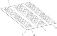
在具体应用时,如图11所示,电源电极4可以只包括一个作用电极41,此时作用电极41可以同时起到连通电路和稳定电压的作用,作用电极41的材料可以选用Ag/AgCl;如图12所示,电源电极2也可以包括一个参比电极42和一个对电极43,此时参比电极42起到稳定电压的作用,对电极43 起到连通电路的作用;对电极43的材料可以选用Au或Pt;参比电极42的材料可以选用Ag/AgCl。In a specific application, as shown in FIG. 11 , the
参照图4所示,为本申请实施例公开的一种制作工作电极的方法,所述方法包括:Referring to FIG. 4 , a method for fabricating a working electrode disclosed in an embodiment of the present application includes:
步骤1031:通过蒸镀或溅射工艺将电极层形成在传感器基底1上,以使电极层覆盖一部分的空心微针阵列2。Step 1031 : forming an electrode layer on the
具体地,在采用蒸镀或溅射工艺来形成电极层时,需要选用带孔洞的掩模板进行蒸镀或溅射,从而实现电极层的图案化。Specifically, when the electrode layer is formed by an evaporation or sputtering process, a mask plate with holes needs to be selected for evaporation or sputtering, so as to realize the patterning of the electrode layer.
步骤1032:在电极层远离传感器基底1的一层形成普鲁士蓝层。Step 1032 : forming a Prussian blue layer on a layer of the electrode layer away from the
具体地,普鲁士蓝层是通过电镀工艺形成在传感器基底1上的。Specifically, the Prussian blue layer is formed on the
步骤1033:在普鲁士蓝层远离电极层的一侧形成试剂酶层。Step 1033 : forming a reagent enzyme layer on the side of the Prussian blue layer away from the electrode layer.
具体地,通过在普鲁士蓝层上覆盖液态的试剂酶,再对液态的试剂酶进行加热干燥,从而形成试剂酶层。Specifically, the reagent enzyme layer is formed by covering the liquid reagent enzyme on the Prussian blue layer, and then heating and drying the liquid reagent enzyme.
步骤1034:在试剂酶层远离普鲁士蓝的一层形成生物兼容性聚合物层。Step 1034 : forming a biocompatible polymer layer on a layer of the reagent enzyme layer away from the Prussian blue.
具体地,通过在试剂酶层上覆盖液态的生物兼容性聚合物,再对液态的生物兼容性聚合物进行加热干燥,从而形成生物兼容性聚合物层。生物兼容性聚合物层可以选用全氟磺酸,生物兼容性聚合物层可以避免普鲁士蓝层对人体造成损害。Specifically, the biocompatible polymer layer is formed by covering the liquid biocompatible polymer on the reagent enzyme layer, and then heating and drying the liquid biocompatible polymer. The biocompatible polymer layer can be selected from perfluorosulfonic acid, and the biocompatible polymer layer can avoid damage to the human body caused by the Prussian blue layer.
这样,在工作电极3接触到被检测溶液时,试剂酶可以与被检测溶液中的对应分析物发生反应,并通过试剂酶反应产生产物,产物会在工作电极3 上进行氧化或者还原反应产生电信号的变化。In this way, when the working
最终形成的微针生物传感器如图7和图9所示,通过将液态聚合物材料铸造在具有微针阵列图案或微针孔阵列图案的模具上,在进行干燥后脱模,从而形成具有内部中空的空心微针阵列2的传感器基底1,再穿透空心微针阵列2中每个微针的尖端,同时在传感器基底1上形成工作电极3和电源电极4,如此便完成了微针传感器的制造;通过直接利用模具形成带有空心微针阵列2的传感器基底1,使得传感器基底的材料可以选择生物可降解材料或生物兼容性材料,从而可以有效提高微针传感器的生物可降解能力或生物兼容性能力。The final formed microneedle biosensor is shown in Fig. 7 and Fig. 9. By casting the liquid polymer material on a mold with a microneedle array pattern or a microneedle hole array pattern, and demolding after drying, it is formed with an internal The
同时,参照图7和图9所示,为了避免工作电极3和电源电极4距离过近而产生短路的情况,在传感器基底1上且位于工作电极3和电源电极4之间设置有隔断区域A,即,位于隔断区域A内的空心微针阵列2未被工作电极3或电源电极4覆盖。此外,参照图11所示,隔断区域A内也可以不形成空心微针阵列2。At the same time, referring to FIG. 7 and FIG. 9 , in order to avoid the short circuit caused by the working
在一种实施例中,在传感器基底1选用壳聚糖材质时,为了避免由于壳聚糖容易吸收水分和膨胀而导致空心微针阵列2被破坏,在形成工作电极3 和电源电极4之前,还可以在传感器基底1上形成隔水层,以避免传感器基底1与溶液接触。In one embodiment, when the
在具体应用时,隔水层可以选用对二甲苯。In specific applications, p-xylene can be selected as the water barrier layer.
此外,在传感器基底1选用不溶于水的材料时,则可以不设置隔水层。In addition, when the
参照图13所示,为本申请实施例公开的微针生物传感器在检测不同浓度的模拟组织液中的葡萄糖浓度时,产生的电流随时间变化的曲线图。由图 13可知,在模拟组织液中的葡萄糖浓度越大时,微针生物传感器所产生的电流也越大。Referring to FIG. 13 , when the microneedle biosensor disclosed in the embodiment of the present application detects the glucose concentration in the simulated tissue fluid of different concentrations, the generated current changes with time as a graph. It can be seen from Figure 13 that the higher the glucose concentration in the simulated tissue fluid, the higher the current generated by the microneedle biosensor.
根据图13所得到的不同浓度下的电流值大小,再以模拟组织液中的葡萄糖浓度大小为横轴,以随葡萄糖浓度增大而增加的电流幅值大小为纵轴,可以得到如图12所示的坐标系,同时在该坐标系中标出不同浓度下的电流幅值,即标出图14中的多个坐标点,并将这些坐标点以直线相连,最终得到图14中的校准曲线。According to the current values at different concentrations obtained in Fig. 13, and then take the glucose concentration in the simulated tissue fluid as the horizontal axis, and take the current amplitude that increases with the increase of the glucose concentration as the vertical axis, we can obtain as shown in Fig. 12 At the same time, the current amplitudes at different concentrations are marked in the coordinate system, that is, multiple coordinate points in Figure 14 are marked, and these coordinate points are connected by a straight line, and finally the calibration curve in Figure 14 is obtained.
最终,根据检测数据可以得到电流增幅与葡萄糖浓度之间的表达式为:Finally, according to the detection data, the expression between the current increase and the glucose concentration can be obtained as:
y=0.117x-0.166y=0.117x-0.166
其中,y代表电流增幅大小,x代表葡萄糖浓度大小。Among them, y represents the magnitude of the current increase, and x represents the magnitude of the glucose concentration.
而根据上述表达式,利用本申请实施例公开的微针传感器检测待检测组织液中的葡萄糖浓度时,在得到检测出来的电流值后,便可以根据公式计算得出待检测组织液中的葡萄糖浓度。According to the above expression, when the microneedle sensor disclosed in the embodiment of the present application is used to detect the glucose concentration in the tissue fluid to be detected, after obtaining the detected current value, the glucose concentration in the tissue fluid to be detected can be calculated according to the formula.
本申请实施例还公开一种微针生物传感器的应用,包括如本申请实施例一提供的微针生物传感器的制造方法所制造的微针传感器,所述微针传感器包括传感器基底及形成在传感器基底上的空心微针阵列;其中,将所述空心微针阵列作为注入通道用于药物注射。The embodiment of the present application also discloses an application of a microneedle biosensor, including the microneedle sensor manufactured by the method for manufacturing the microneedle biosensor provided in the first embodiment of the present application. The microneedle sensor includes a sensor substrate and a sensor formed on the sensor. A hollow microneedle array on a substrate; wherein, the hollow microneedle array is used as an injection channel for drug injection.
通过在空心微针阵列2的微针上形成孔洞,使得微针传感器在实际应用时,例如,在使用微针传感器对人体组织液中的葡萄糖浓度时,可以将空心微针阵列2中的带有孔洞的空心微针作为注入通道朝向人体内注入药物,并且根据微针传感器测试的葡萄糖浓度选择注入药物的类型及速率等,从而使得微针传感器的使用更加便利;这也是在本申请中微针传感器需要形成具有空心微针阵列2的传感器基底1的主要原因。By forming holes on the microneedles of the
需要说明的是,本说明书中的各个实施例均采用递进的方式描述,每个实施例重点说明的都是与其他实施例的不同之处,各个实施例之间相同相似的部分互相参见即可。It should be noted that the various embodiments in this specification are described in a progressive manner, and each embodiment focuses on the differences from other embodiments. For the same and similar parts among the various embodiments, refer to each other Can.
还需要说明的是,在本文中,术语“中心”、“上”、“下”、“左”、“右”、“竖直”、“水平”、“内”、“外”等指示的方位或位置关系为基于附图所示的方位或位置关系,仅是为了便于描述本申请和简化描述,而不是指示或暗示所指的装置或元件必须具有特定的方位、以特定的方位构造和操作,因此不能理解为对本申请的限制。此外,诸如“第一”和“第二”之类的关系术语仅仅用来将一个实体或者操作与另一个实体或操作区分开来,而不一定要求或者暗示这些实体或操作之间存在任何这种实际的关系或者顺序,也不能理解为指示或暗示相对重要性。而且,术语“包括”、“包含”或者其任何其他变体意在涵盖非排他性的包含,从而使得包括一系列要素的过程、方法、物品或者终端设备不仅包括那些要素,而且还包括没有明确列出的其他要素,或者是还包括为这种过程、方法、物品或者终端设备所固有的要素。在没有更多限制的情况下,由语句“包括一个……”限定的要素,并不排除在包括要素的过程、方法、物品或者终端设备中还存在另外的相同要素。It should also be noted that, in this document, the terms "center", "upper", "lower", "left", "right", "vertical", "horizontal", "inner", "outer", etc. The orientation or positional relationship is based on the orientation or positional relationship shown in the drawings, which is only for the convenience of describing the present application and simplifying the description, rather than indicating or implying that the device or element referred to must have a specific orientation, be constructed and operation, and therefore should not be construed as a limitation of this application. Furthermore, relational terms such as "first" and "second" are only used to distinguish one entity or operation from another entity or operation, and do not necessarily require or imply that any such relationship exists between those entities or operations. an actual relationship or order, nor should it be construed to indicate or imply relative importance. Moreover, the terms "comprising", "comprising" or any other variation thereof are intended to encompass non-exclusive inclusion such that a process, method, article or terminal device that includes a list of elements includes not only those elements, but also a non-exclusive list of elements. other elements, or also include elements inherent to such a process, method, article or terminal equipment. Without further limitation, an element defined by the phrase "comprises a..." does not preclude the presence of additional identical elements in the process, method, article, or terminal device that includes the element.
以上对本申请所提供的技术方案进行了详细介绍,本文中应用了具体个例对本申请的原理及实施方式进行了阐述,以上实施例的说明只是用于帮助理解本申请,本说明书内容不应理解为对本申请的限制。同时,对于本领域的一般技术人员,依据本申请,在具体实施方式及应用范围上均会有不同形式的改变之处,这里无需也无法对所有的实施方式予以穷举,而由此所引伸出的显而易见的变化或变动仍处于本申请的保护范围之中。The technical solutions provided by the present application have been introduced in detail above, and the principles and implementations of the present application have been described with specific examples herein. The descriptions of the above embodiments are only used to help the understanding of the present application, and the contents of this specification should not be understood. to limit this application. At the same time, for those of ordinary skill in the art, according to the present application, there will be different forms of changes in the specific embodiments and application scope. It is unnecessary and impossible to list all the embodiments here. The obvious changes or changes are still within the protection scope of the present application.
Claims (9)
Priority Applications (2)
| Application Number | Priority Date | Filing Date | Title |
|---|---|---|---|
| CN202210393852.6ACN114935595B (en) | 2022-04-15 | 2022-04-15 | Manufacturing method of microneedle biosensor |
| US18/134,730US20230330403A1 (en) | 2022-04-15 | 2023-04-14 | Manufacturing method of microneedle biosensor |
Applications Claiming Priority (1)
| Application Number | Priority Date | Filing Date | Title |
|---|---|---|---|
| CN202210393852.6ACN114935595B (en) | 2022-04-15 | 2022-04-15 | Manufacturing method of microneedle biosensor |
Publications (2)
| Publication Number | Publication Date |
|---|---|
| CN114935595Atrue CN114935595A (en) | 2022-08-23 |
| CN114935595B CN114935595B (en) | 2024-02-06 |
Family
ID=82863282
Family Applications (1)
| Application Number | Title | Priority Date | Filing Date |
|---|---|---|---|
| CN202210393852.6AActiveCN114935595B (en) | 2022-04-15 | 2022-04-15 | Manufacturing method of microneedle biosensor |
Country Status (2)
| Country | Link |
|---|---|
| US (1) | US20230330403A1 (en) |
| CN (1) | CN114935595B (en) |
Cited By (2)
| Publication number | Priority date | Publication date | Assignee | Title |
|---|---|---|---|---|
| CN117783248A (en)* | 2023-12-28 | 2024-03-29 | 北京大学 | A flexible wearable potassium ion detection sensor and its preparation method |
| CN118383761A (en)* | 2024-06-26 | 2024-07-26 | 北京大学 | Graphene electrode microneedle biosensor and construction method |
Citations (8)
| Publication number | Priority date | Publication date | Assignee | Title |
|---|---|---|---|---|
| US20020020688A1 (en)* | 1999-06-09 | 2002-02-21 | The Procter & Gamble Company | Apparatus and method for manufacturing an intracutaneous microneedle array |
| US20060015061A1 (en)* | 2004-07-16 | 2006-01-19 | Shih-Chi Kuo | Microneedle array device and its fabrication method |
| CN1986011A (en)* | 2006-12-08 | 2007-06-27 | 中国科学院上海微系统与信息技术研究所 | Miniature needle array for medicine transmission and its making process |
| US20140336487A1 (en)* | 2011-09-02 | 2014-11-13 | Joseph Wang | Microneedle arrays for biosensing and drug delivery |
| CN112858430A (en)* | 2021-01-08 | 2021-05-28 | 中山大学 | Sensor for detecting plant active small molecules and preparation method |
| CN113546294A (en)* | 2020-04-23 | 2021-10-26 | 北京大学第一医院 | A microneedle self-detection and treatment device |
| CN113777145A (en)* | 2021-09-14 | 2021-12-10 | 北京大学 | Method for manufacturing micro-needle biosensor |
| CN113977829A (en)* | 2021-09-08 | 2022-01-28 | 北京宝理泰科技有限公司 | Preparation method of hollow microneedle array biosensor |
- 2022
- 2022-04-15CNCN202210393852.6Apatent/CN114935595B/enactiveActive
- 2023
- 2023-04-14USUS18/134,730patent/US20230330403A1/enactivePending
Patent Citations (8)
| Publication number | Priority date | Publication date | Assignee | Title |
|---|---|---|---|---|
| US20020020688A1 (en)* | 1999-06-09 | 2002-02-21 | The Procter & Gamble Company | Apparatus and method for manufacturing an intracutaneous microneedle array |
| US20060015061A1 (en)* | 2004-07-16 | 2006-01-19 | Shih-Chi Kuo | Microneedle array device and its fabrication method |
| CN1986011A (en)* | 2006-12-08 | 2007-06-27 | 中国科学院上海微系统与信息技术研究所 | Miniature needle array for medicine transmission and its making process |
| US20140336487A1 (en)* | 2011-09-02 | 2014-11-13 | Joseph Wang | Microneedle arrays for biosensing and drug delivery |
| CN113546294A (en)* | 2020-04-23 | 2021-10-26 | 北京大学第一医院 | A microneedle self-detection and treatment device |
| CN112858430A (en)* | 2021-01-08 | 2021-05-28 | 中山大学 | Sensor for detecting plant active small molecules and preparation method |
| CN113977829A (en)* | 2021-09-08 | 2022-01-28 | 北京宝理泰科技有限公司 | Preparation method of hollow microneedle array biosensor |
| CN113777145A (en)* | 2021-09-14 | 2021-12-10 | 北京大学 | Method for manufacturing micro-needle biosensor |
Non-Patent Citations (1)
| Title |
|---|
| DEVIN V. MCALLISTER 等: "Microfabricated needles for transdermal delivery of macromolecules and nanoparticles: Fabrication methods and transport studies", 《PNAS》* |
Cited By (3)
| Publication number | Priority date | Publication date | Assignee | Title |
|---|---|---|---|---|
| CN117783248A (en)* | 2023-12-28 | 2024-03-29 | 北京大学 | A flexible wearable potassium ion detection sensor and its preparation method |
| CN117783248B (en)* | 2023-12-28 | 2025-01-28 | 北京大学 | A flexible wearable potassium ion detection sensor and preparation method thereof |
| CN118383761A (en)* | 2024-06-26 | 2024-07-26 | 北京大学 | Graphene electrode microneedle biosensor and construction method |
Also Published As
| Publication number | Publication date |
|---|---|
| US20230330403A1 (en) | 2023-10-19 |
| CN114935595B (en) | 2024-02-06 |
Similar Documents
| Publication | Publication Date | Title |
|---|---|---|
| Luo et al. | Microneedles: materials, fabrication, and biomedical applications | |
| US20230330403A1 (en) | Manufacturing method of microneedle biosensor | |
| TWI519781B (en) | Transdermal microneedle array patch | |
| US8361037B2 (en) | Microneedles, microneedle arrays, and systems and methods relating to same | |
| US20090062752A1 (en) | Switchcable microneedle arrays and systems and methods relating to same | |
| CN113777145B (en) | A method for manufacturing a microneedle biosensor | |
| Liu et al. | Protection of nanostructures-integrated microneedle biosensor using dissolvable polymer coating | |
| US20140166612A1 (en) | Analyte sensor and fabrication methods | |
| US20060163215A1 (en) | Process for producing pad based for transdermal drug administration, pad base for transdermal drug administration and needle | |
| CN108845012A (en) | A kind of conducting polymer microneedle electrodes and preparation method thereof for biomolecule detection | |
| GB2481901A (en) | Microneedle arrays | |
| CN104970805B (en) | Transdermal micro-needle array patch and manufacturing method thereof | |
| Azizi Machekposhti et al. | Microneedle fabrication methods and applications | |
| CN116831569A (en) | Dynamic continuous blood glucose sensor based on resin substrate microneedle electrode array | |
| CN113977829A (en) | Preparation method of hollow microneedle array biosensor | |
| CN114939100A (en) | High-density random curved surface polymer microneedle array and preparation method and application thereof | |
| CN116531610B (en) | Closed loop system of diabetes sensor and manufacturing method thereof | |
| CN115326891B (en) | Flexible blood glucose concentration sensor and preparation method thereof | |
| JP2024007521A (en) | Electrode for glucose sensors | |
| US20210228119A1 (en) | Microneedle biosensor | |
| CN203555741U (en) | Microelectrode of micron-scale glucose sensor | |
| Haider et al. | Wire bonded solid metal microneedles: a versatile platform technology for transdermal drug delivery and biosensing | |
| CN216051504U (en) | Microneedle biosensor manufactured in full-printing mode | |
| CN108836354A (en) | A kind of preparation method of microneedle array biosensor | |
| CN113288138A (en) | Microneedle array electrode, sensor and preparation method thereof |
Legal Events
| Date | Code | Title | Description |
|---|---|---|---|
| PB01 | Publication | ||
| PB01 | Publication | ||
| SE01 | Entry into force of request for substantive examination | ||
| SE01 | Entry into force of request for substantive examination | ||
| GR01 | Patent grant | ||
| GR01 | Patent grant |