CN114931348A - Interventional needles and rigid endoscopes for rigid endoscopes - Google Patents
Interventional needles and rigid endoscopes for rigid endoscopesDownload PDFInfo
- Publication number
- CN114931348A CN114931348ACN202210735925.5ACN202210735925ACN114931348ACN 114931348 ACN114931348 ACN 114931348ACN 202210735925 ACN202210735925 ACN 202210735925ACN 114931348 ACN114931348 ACN 114931348A
- Authority
- CN
- China
- Prior art keywords
- needle
- imaging
- sensing
- target site
- fiber
- Prior art date
- Legal status (The legal status is an assumption and is not a legal conclusion. Google has not performed a legal analysis and makes no representation as to the accuracy of the status listed.)
- Pending
Links
Images


Classifications
- A—HUMAN NECESSITIES
- A61—MEDICAL OR VETERINARY SCIENCE; HYGIENE
- A61B—DIAGNOSIS; SURGERY; IDENTIFICATION
- A61B1/00—Instruments for performing medical examinations of the interior of cavities or tubes of the body by visual or photographical inspection, e.g. endoscopes; Illuminating arrangements therefor
- A61B1/012—Instruments for performing medical examinations of the interior of cavities or tubes of the body by visual or photographical inspection, e.g. endoscopes; Illuminating arrangements therefor characterised by internal passages or accessories therefor
- A61B1/018—Instruments for performing medical examinations of the interior of cavities or tubes of the body by visual or photographical inspection, e.g. endoscopes; Illuminating arrangements therefor characterised by internal passages or accessories therefor for receiving instruments
- A—HUMAN NECESSITIES
- A61—MEDICAL OR VETERINARY SCIENCE; HYGIENE
- A61B—DIAGNOSIS; SURGERY; IDENTIFICATION
- A61B1/00—Instruments for performing medical examinations of the interior of cavities or tubes of the body by visual or photographical inspection, e.g. endoscopes; Illuminating arrangements therefor
- A61B1/06—Instruments for performing medical examinations of the interior of cavities or tubes of the body by visual or photographical inspection, e.g. endoscopes; Illuminating arrangements therefor with illuminating arrangements
- A61B1/07—Instruments for performing medical examinations of the interior of cavities or tubes of the body by visual or photographical inspection, e.g. endoscopes; Illuminating arrangements therefor with illuminating arrangements using light-conductive means, e.g. optical fibres
- A—HUMAN NECESSITIES
- A61—MEDICAL OR VETERINARY SCIENCE; HYGIENE
- A61B—DIAGNOSIS; SURGERY; IDENTIFICATION
- A61B17/00—Surgical instruments, devices or methods
- A61B17/00234—Surgical instruments, devices or methods for minimally invasive surgery
- A—HUMAN NECESSITIES
- A61—MEDICAL OR VETERINARY SCIENCE; HYGIENE
- A61B—DIAGNOSIS; SURGERY; IDENTIFICATION
- A61B17/00—Surgical instruments, devices or methods
- A61B17/34—Trocars; Puncturing needles
- A—HUMAN NECESSITIES
- A61—MEDICAL OR VETERINARY SCIENCE; HYGIENE
- A61B—DIAGNOSIS; SURGERY; IDENTIFICATION
- A61B17/00—Surgical instruments, devices or methods
- A61B17/00234—Surgical instruments, devices or methods for minimally invasive surgery
- A61B2017/00292—Surgical instruments, devices or methods for minimally invasive surgery mounted on or guided by flexible, e.g. catheter-like, means
- A61B2017/00296—Surgical instruments, devices or methods for minimally invasive surgery mounted on or guided by flexible, e.g. catheter-like, means mounted on an endoscope
Landscapes
- Health & Medical Sciences (AREA)
- Life Sciences & Earth Sciences (AREA)
- Surgery (AREA)
- Nuclear Medicine, Radiotherapy & Molecular Imaging (AREA)
- Molecular Biology (AREA)
- Veterinary Medicine (AREA)
- Public Health (AREA)
- General Health & Medical Sciences (AREA)
- Animal Behavior & Ethology (AREA)
- Engineering & Computer Science (AREA)
- Biomedical Technology (AREA)
- Heart & Thoracic Surgery (AREA)
- Medical Informatics (AREA)
- Pathology (AREA)
- Physics & Mathematics (AREA)
- Biophysics (AREA)
- Radiology & Medical Imaging (AREA)
- Optics & Photonics (AREA)
- Infusion, Injection, And Reservoir Apparatuses (AREA)
Abstract
Description
Translated fromChinese技术领域technical field
本公开涉及医疗器械领域,并且更具体地,涉及一种用于硬式内窥镜的介入针和硬式内窥镜。The present disclosure relates to the field of medical devices, and more particularly, to an interventional needle and a rigid endoscope for a rigid endoscope.
背景技术Background technique
硬式内窥镜是一种不可弯曲的内窥镜,其主要通过外科切口进入活体的体腔内,可用于微创外科手术中的术中成像。在医生利用现有的硬式内窥镜观察病患体内的目标部位(例如肿瘤之类的病变部位)前,需要向病患体内充入气体(通常是二氧化碳)以形成人工气腔(例如,胸腔检查时的气胸、腹腔检查时的气腹等)从而拓展手术空间。但是,医生只能观察到目标部位的表面特征,而无法观察目标部位的深层次的结构。此外,当医生利用硬式内窥镜携带介入针或其组件(诸如但不限于经皮穿刺针套件)等介入器械进入病患体内以对目标部位进行诸如穿刺之类的介入诊疗操作时,介入针的操作自由度可能受到介入针与硬式内窥镜之间的附接的限制,并且介入针的实际进针位置与硬式内窥镜的观察视野也可能存在一定偏离,而介入针通常进入到病患体内较深的位置,因此操作介入针的医生往往无法直接看见介入针所在位置的情形,更无法及时准确地掌握病患体内瞬息万变的状况,导致难以即时做出可靠的判断与决策,进而无法高效地进行介入手术期间的诊断与治疗。Rigid endoscope is an inflexible endoscope, which mainly enters the body cavity of a living body through a surgical incision, and can be used for intraoperative imaging in minimally invasive surgery. Before doctors can use existing rigid endoscopes to observe a target site in a patient (eg, a lesion such as a tumor), gas (usually carbon dioxide) needs to be filled into the patient's body to form an artificial air cavity (eg, a thoracic cavity). Pneumothorax during examination, pneumoperitoneum during abdominal examination, etc.) to expand the surgical space. However, doctors can only observe the surface features of the target site, but cannot observe the deep structure of the target site. In addition, when a doctor uses a rigid endoscope to carry an interventional needle or an interventional instrument such as a percutaneous needle kit (such as but not limited to a percutaneous needle kit) into a patient's body to perform an interventional diagnosis and treatment operation such as puncturing the target site, the interventional needle The operational freedom of the interventional needle may be limited by the attachment between the interventional needle and the rigid endoscope, and there may be some deviation between the actual needle insertion position of the interventional needle and the observation field of the rigid endoscope, and the interventional needle usually enters the patient Due to the deep position in the patient's body, doctors who operate the interventional needle often cannot directly see the position of the interventional needle, and they cannot grasp the rapidly changing situation in the patient's body in a timely and accurate manner, which makes it difficult to make reliable judgments and decisions in real time. Efficient diagnosis and treatment during interventional procedures.
发明内容SUMMARY OF THE INVENTION
在下文中给出了关于本公开的简要概述,以便提供关于本公开的一些方面的基本理解。但是,应当理解,这个概述并不是关于本公开的穷举性概述。它并不是意图用来确定本公开的关键性部分或重要部分,也不是意图用来限定本公开的范围。其目的仅仅是以简化的形式给出关于本公开的某些概念,以此作为稍后给出的更详细描述的前序。The following presents a brief summary of the disclosure in order to provide a basic understanding of some aspects of the disclosure. It should be understood, however, that this summary is not an exhaustive overview of the present disclosure. It is not intended to identify key or critical parts of the disclosure nor to limit the scope of the disclosure. Its sole purpose is to present some concepts related to the disclosure in a simplified form as a prelude to the more detailed description that is presented later.
根据本公开的一方面,提供了一种用于硬式内窥镜的介入针,其中,所述介入针包括针体,所述针体被配置为能经皮介入活体,其中,所述针体具有中空结构,以在所述针体内部提供工作通道,所述工作通道关于所述针体的中心轴线偏心地布置在所述针体中。According to an aspect of the present disclosure, there is provided an interventional needle for a rigid endoscope, wherein the interventional needle includes a needle body configured to be capable of percutaneously intervening in a living body, wherein the needle body A hollow structure is provided to provide a working channel inside the needle body, the working channel being arranged in the needle body eccentrically with respect to the central axis of the needle body.
在一些实施例中,在所述介入针的横截面中,所述工作通道的外周面与所述针体的外周面之间的最小距离可以不超过0.1mm。In some embodiments, in the cross section of the interventional needle, the minimum distance between the outer peripheral surface of the working channel and the outer peripheral surface of the needle body may not exceed 0.1 mm.
在一些实施例中,所述介入针可以包括至少一个成像光纤束,所述至少一个成像光纤束布置在所述针体中并且沿所述针体的中心轴线纵向地延伸,所述至少一个成像光纤束的前光纤端面位于所述针体的前端面处,其中,所述至少一个成像光纤束被配置为朝向所述活体内的目标部位发射成像探测光并接收来自所述目标部位的成像响应光,以便基于所述成像响应光对所述目标部位成像。In some embodiments, the interventional needle may include at least one imaging fiber optic bundle disposed in the needle body and extending longitudinally along a central axis of the needle body, the at least one imaging fiber optic bundle A front fiber end face of the fiber optic bundle is located at the front end face of the needle, wherein the at least one imaging fiber bundle is configured to emit imaging probe light and receive imaging responses from the target site toward the in vivo target site light to image the target site based on the imaging response light.
在一些实施例中,所述至少一个成像光纤束中的每个成像光纤束可以被配置为单独地朝向所述活体内的目标部位发射成像探测光并接收来自所述目标部位的成像响应光,并且所述至少一个成像光纤束中的每个成像光纤束在其前光纤端面处附接有与该成像光纤束尺寸相当的物镜。In some embodiments, each of the at least one imaging fiber bundle may be configured to individually emit imaging probe light toward and receive imaging response light from the target site toward the target site in the living body, And each of the at least one imaging fiber bundle has an objective lens commensurate with the size of the imaging fiber bundle attached at its front fiber end face.
在一些实施例中,所述至少一个成像光纤束可以包括关于所述针体的所述中心轴线对称地布置在所述针体中的两个或更多个成像光纤束,以便基于所述成像响应光的信号强度在所述两个或更多个成像光纤束当中的分布情况确定所述针体的进针方向相对于所述目标部位的中心方向的偏离情况。In some embodiments, the at least one imaging fiber optic bundle may include two or more imaging fiber optic bundles arranged in the needle body symmetrically about the central axis of the needle body, in order to base the imaging on the The distribution of the signal intensity of the response light among the two or more imaging fiber bundles determines the deviation of the needle advancing direction of the needle body relative to the central direction of the target site.
在一些实施例中,所述至少一个成像光纤束可以包括被配置为朝向所述活体内的目标部位发射成像探测光的第一组成像光纤束以及被配置为接收来自所述目标部位的成像响应光的第二组成像光纤束,所述第一组成像光纤束中的一个或多个成像光纤束与所述第二组成像光纤束中的相应一个或多个成像光纤束相邻地定位,并且所述第二组成像光纤束中的每个成像光纤束在其前光纤端面处附接有与该成像光纤束尺寸相当的物镜。In some embodiments, the at least one imaging fiber optic bundle may include a first set of imaging fiber optic bundles configured to emit imaging probe light toward a target site in the in vivo and configured to receive imaging responses from the target site a second set of imaging fiber bundles, one or more imaging fiber bundles of the first set of imaging fiber bundles positioned adjacent to corresponding one or more imaging fiber bundles of the second set of imaging fiber bundles, And each imaging fiber bundle in the second set of imaging fiber bundles has an objective lens commensurate with the size of the imaging fiber bundle attached at its front fiber end face.
在一些实施例中,在所述介入针的横截面中,所述至少一个成像光纤束中的每个成像光纤束的外周面可以与所述工作通道的外周面之间的最小距离不超过0.1mm。In some embodiments, the minimum distance between the outer peripheral surface of each imaging fiber bundle in the at least one imaging fiber bundle and the outer peripheral surface of the working channel may not exceed 0.1 in the cross section of the interventional needle mm.
在一些实施例中,所述至少一个成像光纤束中的每个成像光纤束的外径的最大值可以为所述针体的外径与所述工作通道的外径之差的至少90%。In some embodiments, the maximum value of the outer diameter of each of the at least one imaging fiber bundle may be at least 90% of the difference between the outer diameter of the needle and the outer diameter of the working channel.
在一些实施例中,所述介入针还可以包括一根或多根照明光纤,所述一根或多根照明光纤布置在所述针体中并且沿所述针体的中心轴线纵向地延伸,所述一根或多根照明光纤的前光纤端面位于所述针体的前端面处,其中,所述一根或多根照明光纤被配置为用于对所述活体内的目标部位进行照明。In some embodiments, the interventional needle may further comprise one or more illumination fibers disposed in the needle body and extending longitudinally along the central axis of the needle body, A front fiber end face of the one or more illumination fibers is located at the front end face of the needle, wherein the one or more illumination fibers are configured to illuminate a target site within the living body.
在一些实施例中,所述一根或多根照明光纤可以包括被配置为发射波长彼此不同的照明光的多根照明光纤。In some embodiments, the one or more illumination fibers may include a plurality of illumination fibers configured to emit illumination light of mutually different wavelengths.
在一些实施例中,所述工作通道可以被配置为用于执行以下操作中的至少一个:输送医疗器械;输送药物;抽吸废液;输送清洗液。In some embodiments, the working channel may be configured to perform at least one of the following operations: delivering a medical device; delivering a drug; aspirating waste fluid; delivering a cleaning fluid.
在一些实施例中,在所述针体内部可以提供至少一个备用通道,所述至少一个备用通道被配置为用于执行以下操作中的至少一个:输送医疗器械;输送药物;抽吸废液;输送清洗液。In some embodiments, at least one alternate channel may be provided within the needle body, the at least one alternate channel configured to perform at least one of the following operations: delivering a medical device; delivering a drug; aspirating waste; Deliver cleaning fluid.
在一些实施例中,所述介入针还可以包括:一组或多组感测光纤,所述一组或多组感测光纤布置在所述针体中并且沿所述针体的中心轴线纵向地延伸,使得所述一组或多组感测光纤的前光纤端面位于所述针体的前端面处,其中,所述一组或多组感测光纤中的每组感测光纤用于感测所述活体内部的微环境的相应一种参数,所述每组感测光纤中的每根感测光纤包括位于其前光纤端面处的具有光致发光材料的探头,所述光致发光材料被配置为具有随所述相应一种参数的变化而变化的发射光谱,并且其中,所述一组或多组感测光纤中的每组感测光纤中的每根感测光纤被配置为朝向所述探头的所述光致发光材料传输激发光并接收来自所述光致发光材料的发射光,以便基于所述光致发光材料的发射光确定所述活体内部的微环境的所述相应一种参数。In some embodiments, the interventional needle may further comprise: one or more sets of sensing fibers disposed in the needle body and longitudinally along the central axis of the needle body extending so that the front fiber end face of the one or more sets of sensing fibers is located at the front end face of the needle body, wherein each set of the one or more sets of sensing fibers is used for sensing A corresponding parameter of the microenvironment inside the living body is measured, and each sensing fiber in each group of sensing fibers includes a probe with a photoluminescent material located at the end face of the front fiber, and the photoluminescent material is is configured to have an emission spectrum that varies as a function of the respective one of the parameters, and wherein each sensing fiber in each of the one or more sets of sensing fibers is configured to face The photoluminescent material of the probe transmits excitation light and receives emitted light from the photoluminescent material to determine the respective one of the microenvironment inside the living body based on the emitted light from the photoluminescent material. kind of parameters.
在一些实施例中,所述一组或多组感测光纤可以包括以下中的一者或多者:第一组感测光纤,包括用于感测所述活体内部的微环境的温度的一根或多根第一感测光纤,所述第一组感测光纤中的每根第一感测光纤的探头具有被配置为具有随温度的变化而变化的发射光谱的第一光致发光材料;第二组感测光纤,包括用于感测所述活体内部的微环境的氧气浓度的一根或多根第二感测光纤,所述第二组感测光纤中的每根第二感测光纤的探头具有被配置为具有随氧气浓度的变化而变化的发射光谱的第二光致发光材料;以及第三组感测光纤,包括用于感测所述活体内部的微环境的酸碱度的一根或多根第三感测光纤,所述第三组感测光纤中的每根第三感测光纤的探头具有被配置为具有随酸碱度的变化而变化的发射光谱的第三光致发光材料。In some embodiments, the one or more sets of sensing fibers may include one or more of the following: a first set of sensing fibers including a sensor for sensing the temperature of a microenvironment inside the living body one or more first sensing fibers, the probe of each first sensing fiber in the first set of sensing fibers having a first photoluminescent material configured to have a temperature-dependent emission spectrum a second set of sensing fibers comprising one or more second sensing fibers for sensing the oxygen concentration of the microenvironment inside the living body, each second sensing fiber in the second set of sensing fibers The probe of the sensing fiber has a second photoluminescent material configured to have an emission spectrum that varies with oxygen concentration; and a third set of sensing fibers including sensors for sensing the pH of the microenvironment inside the living body one or more third sensing fibers, the probe of each third sensing fiber in the third set of sensing fibers having a third photoluminescence configured to have an emission spectrum that varies with changes in pH Material.
在一些实施例中,所述介入针还可以包括可移除地设置于所述针体的所述工作通道内的内针,所述内针可操作以在所述针体被导航到所述目标部位处或附近时进入到所述目标部位内部。In some embodiments, the interventional needle may further comprise an inner needle removably disposed within the working channel of the needle body, the inner needle operable to be navigated to the needle body when the needle body is navigated to the into the interior of the target site when at or near the target site.
在一些实施例中,所述内针可以包括布置在所述内针中的一个或多个成像光纤束,所述一个或多个成像光纤束沿所述内针的中心轴线纵向地延伸并且具有位于所述内针的前端面处或附近的前光纤端面,所述一个或多个成像光纤束中的每个成像光纤束在其前光纤端面处附接有与该成像光纤束尺寸相当的物镜,其中,所述一个或多个成像光纤束被配置为朝向所述活体内的目标部位发射成像探测光并接收来自所述目标部位的成像响应光,以便基于所述成像响应光对所述目标部位成像。In some embodiments, the inner needle may include one or more imaging fiber optic bundles disposed within the inner needle, the one or more imaging fiber optic bundles extending longitudinally along the central axis of the inner needle and having a front fiber end face at or near the front end face of the inner needle, each of the one or more imaging fiber bundles having an objective lens commensurate with the imaging fiber bundle attached at its front fiber end face , wherein the one or more imaging fiber bundles are configured to emit imaging probe light toward and receive imaging response light from the target site toward a target site in the living body, so as to target the target based on the imaging response light site imaging.
在一些实施例中,所述内针可以包括布置在所述内针中的一组或多组感测光纤,所述一组或多组感测光纤沿所述内针的中心轴线纵向地延伸并且具有位于所述内针的前端面处或附近的前光纤端面,其中,所述一组或多组感测光纤中的每组感测光纤用于感测所述目标部位内部的微环境的相应一种参数,所述每组感测光纤中的每根感测光纤包括位于其前光纤端面处的具有光致发光材料的探头,所述光致发光材料被配置为具有随所述相应一种参数的变化而变化的发射光谱,并且其中,所述一组或多组感测光纤中的每组感测光纤中的每根感测光纤被配置为朝向所述探头的所述光致发光材料传输激发光并接收来自所述光致发光材料的发射光,以便基于所述光致发光材料的发射光确定所述目标部位内部的微环境的所述相应一种参数。In some embodiments, the inner needle may include one or more sets of sensing fibers disposed in the inner needle, the one or more sets of sensing fibers extending longitudinally along the central axis of the inner needle and has a front fiber end face located at or near the front end face of the inner needle, wherein each of the one or more sets of sensing fibers is used to sense the microenvironment inside the target site. Corresponding to a parameter, each sensing fiber in each set of sensing fibers includes a probe having a photoluminescent material at its front fiber end face, the photoluminescent material being configured to have a an emission spectrum that varies with a change in a parameter, and wherein each sensing fiber in each of the one or more sets of sensing fibers is configured to photoluminescence toward the probe The material transmits excitation light and receives emitted light from the photoluminescent material to determine the respective one of the parameters of the microenvironment within the target site based on the emitted light from the photoluminescent material.
在一些实施例中,所述一组或多组感测光纤可以包括以下中的一者或多者:第一组感测光纤,包括用于感测所述目标部位内部的微环境的温度的一根或多根第一感测光纤,所述第一组感测光纤中的每根第一感测光纤的探头具有被配置为具有随温度的变化而变化的发射光谱的第一光致发光材料;第二组感测光纤,包括用于感测所述目标部位内部的微环境的氧气浓度的一根或多根第二感测光纤,所述第二组感测光纤中的每根第二感测光纤的探头具有被配置为具有随氧气浓度的变化而变化的发射光谱的第二光致发光材料;以及第三组感测光纤,包括用于感测所述目标部位内部的微环境的酸碱度的一根或多根第三感测光纤,所述第三组感测光纤中的每根第三感测光纤的探头具有被配置为具有随酸碱度的变化而变化的发射光谱的第三光致发光材料。In some embodiments, the one or more sets of sensing fibers may include one or more of the following: a first set of sensing fibers including sensors for sensing the temperature of the microenvironment inside the target site One or more first sensing fibers, the probe of each first sensing fiber in the first set of sensing fibers having a first photoluminescence configured to have a temperature-dependent emission spectrum material; a second set of sensing fibers, including one or more second sensing fibers for sensing the oxygen concentration of the microenvironment inside the target site, each of the second sensing fibers in the second set of sensing fibers A two sensing fiber probe having a second photoluminescent material configured to have an emission spectrum that varies with oxygen concentration; and a third set of sensing fibers including for sensing the microenvironment within the target site one or more third sensing fibers for pH, each of the third sensing fibers in the third set of sensing fibers having a probe having a third sensor configured to have an emission spectrum that varies as a function of pH Photoluminescent material.
在一些实施例中,所述一组或多组感测光纤中的每组感测光纤可以各自关于所述内针的所述中心轴线旋转对称地布置在所述内针中,并且其中,所述内针可以具有中空通道,用于对所述目标部位注射化学消融药物。In some embodiments, each of the one or more sets of sensing fibers may be each disposed in the inner needle rotationally symmetrically about the central axis of the inner needle, and wherein the The inner needle may have a hollow channel for injecting a chemical ablative drug to the target site.
在一些实施例中,所述内针可以被配置用于对所述目标部位进行热消融,并且包括布置在所述内针中的一组或多组温度感测光纤,所述一组或多组温度感测光纤沿所述内针的中心轴线纵向地延伸,并且所述一组或多组温度感测光纤中的每组温度感测光纤的前光纤端面位于所述内针的从前端面到后端面之间的相应一个横截面处,其中,所述一组或多组温度感测光纤中的每组温度感测光纤用于感测所述目标部位内部的微环境的温度,所述每组温度感测光纤中的每根温度感测光纤包括位于其前光纤端面处的具有光致发光材料的探头,所述光致发光材料被配置为具有随温度的变化而变化的发射光谱,并且其中,所述一组或多组温度感测光纤中的每组温度感测光纤中的每根温度感测光纤被配置为朝向所述探头的所述光致发光材料传输激发光并接收来自所述光致发光材料的发射光,以便基于所述光致发光材料的发射光确定所述目标部位内部的微环境的温度。In some embodiments, the inner needle may be configured for thermal ablation of the target site and include one or more sets of temperature sensing fibers disposed in the inner needle, the one or more sets of temperature sensing fibers Sets of temperature sensing fibers extend longitudinally along the central axis of the inner needle, and a front fiber end face of each of the one or more sets of temperature sensing fibers is located on the inner needle from the front end face to At a corresponding one of the cross-sections between the rear faces, wherein each group of temperature sensing fibers in the one or more groups of temperature sensing fibers is used to sense the temperature of the microenvironment inside the target site, and each group of the temperature sensing fibers is used for sensing the temperature of the microenvironment inside the target site, Each temperature sensing fiber in the set of temperature sensing fibers includes a probe at its front fiber end face having a photoluminescent material configured to have an emission spectrum that varies with temperature, and wherein each temperature sensing fiber in each of the one or more groups of temperature sensing fibers is configured to transmit excitation light toward the photoluminescent material of the probe and receive The emitted light of the photoluminescent material is used to determine the temperature of the microenvironment inside the target site based on the emitted light of the photoluminescent material.
在一些实施例中,所述一组或多组温度感测光纤中的第一组温度感测光纤可以相对于所述一组或多组温度感测光纤中的第二组温度感测光纤更靠近所述内针的前端面,并且所述第一组温度感测光纤的温度感测光纤密度大于所述第二组温度感测光纤的温度感测光纤密度,所述温度感测光纤密度是一组温度感测光纤的数量与该组温度感测光纤的前光纤端面所在的内针横截面的面积之比。In some embodiments, a first set of temperature sensing fibers of the one or more sets of temperature sensing fibers may be more flexible relative to a second set of temperature sensing fibers of the one or more sets of temperature sensing fibers close to the front end face of the inner needle, and the temperature sensing fiber density of the first group of temperature sensing fibers is greater than the temperature sensing fiber density of the second group of temperature sensing fibers, and the temperature sensing fiber density is The ratio of the number of a group of temperature sensing fibers to the area of the inner needle cross-section where the front fiber end face of the group of temperature sensing fibers is located.
在一些实施例中,所述介入针还可以包括布置在所述针体中的导航光纤束,所述导航光纤束沿所述针体的所述中心轴线纵向地延伸并且具有位于所述针体的前端面处的前光纤端面,其中,所述导航光纤束被配置为向所述活体内部发射导航探测光并接收源自所述导航探测光的导航响应光,以便基于所述导航响应光定位并区分所述活体内部的不期望被所述介入针刺入的部位。In some embodiments, the interventional needle may further include a navigation fiber optic bundle disposed in the needle body, the navigation fiber optic bundle extending longitudinally along the central axis of the needle body and having The front fiber end face at the front end face of the navigation fiber bundle is configured to emit navigation probe light into the living body and receive navigation response light from the navigation probe light for localization based on the navigation response light And distinguish the parts inside the living body that are not expected to be pierced by the intervention needle.
根据本公开的另一方面,提供了一种硬式内窥镜,所述硬式内窥镜包括根据本公开的前述方面的任一实施例所述的用于硬式内窥镜的介入针。According to another aspect of the present disclosure, there is provided a rigid endoscope comprising an interventional needle for a rigid endoscope according to any embodiment of the preceding aspects of the present disclosure.
通过以下参照附图对本公开的示例性实施例的详细描述,本公开的其它特征及其优点将会变得更为清楚。Other features of the present disclosure and advantages thereof will become more apparent from the following detailed description of exemplary embodiments of the present disclosure with reference to the accompanying drawings.
附图说明Description of drawings
构成说明书的一部分的附图描述了本公开的实施例,并且连同说明书一起用于解释本公开的原理。在附图中阐述的实施例本质上是说明性和示例性的,并不旨在限制本公开。当结合以下附图阅读时,可以清楚地理解以下对示例性实施例的详细描述,其中相似的结构用相似的附图标记指示,并且其中:The accompanying drawings, which form a part of the specification, illustrate embodiments of the present disclosure and together with the description serve to explain the principles of the present disclosure. The embodiments set forth in the figures are illustrative and exemplary in nature and are not intended to limit the present disclosure. The following detailed description of exemplary embodiments can be clearly understood when read in conjunction with the following drawings, wherein like structures are designated by like reference numerals, and wherein:
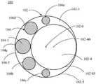
图1是示意性示出了根据本公开的一个或多个示例性实施例的用于硬式内窥镜的介入针的俯视图;1 is a top view schematically illustrating an interventional needle for a rigid endoscope according to one or more exemplary embodiments of the present disclosure;
图2是示意性示出了根据本公开的一个或多个示例性实施例的用于硬式内窥镜的介入针的侧视图;2 is a side view schematically illustrating an interventional needle for a rigid endoscope according to one or more exemplary embodiments of the present disclosure;
图3是示意性示出了根据本公开的一个或多个示例性实施例的用于硬式内窥镜的介入针中的成像光纤束的结构示图;3 is a structural diagram schematically illustrating an imaging fiber bundle in an interventional needle for a rigid endoscope according to one or more exemplary embodiments of the present disclosure;
图4A至图4C分别示意性示出了根据本公开的一个或多个示例性实施例的用于硬式内窥镜的介入针的成像光纤束的几种示例布置方式;4A to 4C respectively schematically illustrate several example arrangements of imaging fiber bundles for an interventional needle of a rigid endoscope according to one or more exemplary embodiments of the present disclosure;
图5是示意性示出了根据本公开的一个或多个示例性实施例的用于硬式内窥镜的介入针的俯视图;5 is a top view schematically illustrating an interventional needle for a rigid endoscope according to one or more exemplary embodiments of the present disclosure;
图6是示意性示出了根据本公开的一个或多个示例性实施例的用于硬式内窥镜的介入针的俯视图;6 is a top view schematically illustrating an interventional needle for a rigid endoscope according to one or more exemplary embodiments of the present disclosure;
图7是示意性示出了根据本公开的一个或多个示例性实施例的用于硬式内窥镜的介入针的俯视图;7 is a top view schematically illustrating an interventional needle for a rigid endoscope according to one or more exemplary embodiments of the present disclosure;
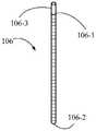
图8是示意性示出了根据本公开的一个或多个示例性实施例的用于硬式内窥镜的介入针中的感测光纤的结构示图;8 is a structural diagram schematically illustrating a sensing fiber in an interventional needle for a rigid endoscope according to one or more exemplary embodiments of the present disclosure;
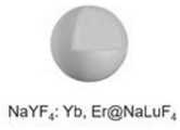
图9A至图9C示出了本公开的一个或多个示例性实施例的用于硬式内窥镜的介入针中的感测光纤的探头所使用的几种示例光致发光材料;9A-9C illustrate several example photoluminescent materials used by probes for sensing optical fibers in interventional needles of rigid endoscopes according to one or more exemplary embodiments of the present disclosure;
图10是示意性示出了根据本公开的一个或多个示例性实施例的用于硬式内窥镜的介入针的一种示例内针的俯视图;10 is a top view schematically illustrating an example inner needle of an interventional needle for a rigid endoscope in accordance with one or more example embodiments of the present disclosure;
图11是示意性示出了根据本公开的一个或多个示例性实施例的用于硬式内窥镜的介入针的另一种示例内针的俯视图;11 is a top view schematically illustrating another example inner needle of an interventional needle for a rigid endoscope according to one or more example embodiments of the present disclosure;
图12A和图12B分别是示意性示出了根据本公开的一个或多个示例性实施例的用于硬式内窥镜的介入针的又一种示例内针的俯视图和侧视图。12A and 12B are top and side views, respectively, schematically illustrating yet another example inner needle of an interventional needle for a rigid endoscope according to one or more example embodiments of the present disclosure.
具体实施方式Detailed ways
下面将参照附图来详细描述本公开的各种示例性实施例。应注意到:除非另外具体说明,否则在这些实施例中阐述的部件和步骤的相对布置、数字表达式和数值不限制本公开的范围。Various exemplary embodiments of the present disclosure will be described in detail below with reference to the accompanying drawings. It should be noted that the relative arrangement of the components and steps, the numerical expressions and numerical values set forth in these embodiments do not limit the scope of the present disclosure unless specifically stated otherwise.
以下对至少一个示例性实施例的描述实际上仅仅是说明性的,决不作为对本公开及其应用或使用的任何限制。也就是说,本文中的结构及方法是以示例性的方式示出,来说明本公开中的结构和方法的不同实施例。然而,本领域技术人员将会理解,它们仅仅说明可以用来实施的本公开的示例性方式,而不是穷尽的方式。此外,附图不必按比例绘制,一些特征可能被放大以示出具体组件的细节。The following description of at least one exemplary embodiment is merely illustrative in nature and is in no way intended to limit the disclosure, its application or uses in any way. That is, the structures and methods herein are shown by way of example to illustrate various embodiments of the structures and methods in the present disclosure. Those skilled in the art will appreciate, however, that they are merely illustrative, and not exhaustive, of the ways in which the disclosure may be practiced. Furthermore, the figures are not necessarily to scale and some features may be exaggerated to show details of particular components.
另外,对于相关领域普通技术人员已知的技术、方法和设备可能不作详细讨论,但在适当情况下,所述技术、方法和设备应当被视为授权说明书的一部分。Additionally, techniques, methods, and apparatus known to those of ordinary skill in the relevant art may not be discussed in detail, but where appropriate, such techniques, methods, and apparatus should be considered part of the authorized specification.
在这里示出和讨论的所有示例中,任何具体值应被解释为仅仅是示例性的,而不是作为限制。因此,示例性实施例的其它示例可以具有不同的值。In all examples shown and discussed herein, any specific value should be construed as illustrative only and not as limiting. Accordingly, other examples of exemplary embodiments may have different values.
医生在对病患进行介入诊疗时,可以利用硬式内窥镜将介入针携带到病患体内,借助于硬式内窥镜对病患体内环境的成像来指导医生将介入针送至病患体内的目标部位(例如,诸如肿瘤之类的病变部位)附近。但是,介入针的操作自由度可能受到介入针与硬式内窥镜之间的附接的限制,并且介入针的实际进针位置与硬式内窥镜的观察视野也可能存在一定偏离,因此医生往往仅能凭经验和手感来把握介入针相对于目标部位的进针方向和位置。而且,现有的硬式内窥镜也无法原位地且实时地对目标部位进行成像并监测目标部位内外的微环境状况,进而无法为医生的即时诊疗决策提供有用的参考信息。When performing interventional diagnosis and treatment on a patient, a doctor can use a rigid endoscope to carry the interventional needle into the patient's body, and use the rigid endoscope to image the patient's internal environment to guide the doctor to send the interventional needle to the patient's body. Near the target site (eg, a diseased site such as a tumor). However, the operation freedom of the interventional needle may be limited by the attachment between the interventional needle and the rigid endoscope, and the actual needle insertion position of the interventional needle may deviate from the observation field of the rigid endoscope, so doctors often The needle insertion direction and position of the interventional needle relative to the target site can only be grasped by experience and feel. Moreover, the existing rigid endoscopes cannot image the target site in situ and in real time and monitor the microenvironment conditions inside and outside the target site, and thus cannot provide useful reference information for doctors' immediate diagnosis and treatment decisions.
为此,本公开提供了一种用于硬式内窥镜的介入针(在下文中简称为介入针),所述介入针具有偏心地布置在所述介入针的针体内的工作通道,由此能够优化介入针的组成部件的空间布局并且因此有利于节省介入针的内部空间,从而有利于介入针的小型化设计。小型化的介入针在与现有的硬式内窥镜一起使用时,其操作自由度更不易受到介入针与硬式内窥镜之间的附接的限制,并且介入针的实际进针位置与硬式内窥镜的观察视野之间的偏离也更小。而且,根据本公开的介入针可以具有光学成像功能,从而可以利用介入针本身直接对活体内部甚至目标部位内部进行成像,因此具有光学成像功能的介入针可以作为硬式内窥镜的一部分,消除了与硬式内窥镜附接的需要从而具有更高的操作自由度,并且介入针的实际进针位置与观察视野变得一致,不仅可以观察到目标部位的表面特征,还可以观察到目标部位的深层次的特征。此外,根据本公开的介入针可以具有光学实时导航功能以高效指导介入针的进针过程,能够在介入针经皮进入活体到达目标部位的过程中规避需要保护的血管、脏器等重要部位。而且,根据本公开的介入针还可以具有微环境原位实时感知功能,能够在介入针经皮进入活体到达目标部位的过程中以及在介入针进入到目标部位之后的过程中原位地且实时地在活体内感测目标部位之外和之内的微环境的各种参数及其分布情况,为医生的即时诊疗决策提供大量有用的参考信息。To this end, the present disclosure provides an interventional needle for a rigid endoscope (hereinafter simply referred to as an interventional needle), the interventional needle having a working channel eccentrically arranged in a needle body of the interventional needle, thereby enabling Optimizing the spatial layout of the components of the interventional needle and thus facilitating the saving of the internal space of the interventional needle and thus the miniaturized design of the interventional needle. When the miniaturized interventional needle is used with the existing rigid endoscope, its freedom of operation is less restricted by the attachment between the interventional needle and the rigid endoscope, and the actual needle insertion position of the interventional needle is different from that of the rigid endoscope. There is also less deviation between the viewing fields of the endoscope. Moreover, the interventional needle according to the present disclosure can have an optical imaging function, so that the interventional needle itself can be used to directly image the inside of the living body or even the inside of the target site. Therefore, the interventional needle with the optical imaging function can be used as a part of the rigid endoscope, eliminating the need for The need for attachment to a rigid endoscope allows for a higher degree of freedom of operation, and the actual needle insertion position of the interventional needle becomes consistent with the observation field, so that not only the surface features of the target site but also the target site can be observed. deep features. In addition, the interventional needle according to the present disclosure can have an optical real-time navigation function to efficiently guide the insertion process of the interventional needle, and can avoid important parts such as blood vessels and organs that need to be protected when the interventional needle percutaneously enters the living body to reach the target site. Moreover, the interventional needle according to the present disclosure may also have a real-time sensing function of the microenvironment in situ, and can perform in-situ and real-time detection during the process of the interventional needle percutaneously entering the living body to reach the target site and the process after the interventional needle enters the target site. Various parameters and their distributions of the microenvironment outside and inside the target site are sensed in vivo, providing a lot of useful reference information for doctors to make immediate diagnosis and treatment decisions.
下面将结合附图详细描述根据本公开的各种实施例的介入针。可以理解,实际的介入针可能还存在其它部件,而为了避免模糊本公开的要点,附图没有示出且本文也不去讨论其它部件。还应注意,在本文中,当提及“前”时是指靠近目标部位而远离操作者(通常是医生)的一侧,当提及“后”时是指远离目标部位而靠近操作者的一侧。An interventional needle according to various embodiments of the present disclosure will be described in detail below with reference to the accompanying drawings. It will be appreciated that other components may also exist in an actual interventional needle, and in order to avoid obscuring the gist of the present disclosure, these components are not shown in the drawings and are not discussed herein. It should also be noted that in this text, when referring to "front", it refers to the side close to the target site and away from the operator (usually the doctor), and when referring to "rear", it refers to the side away from the target site and closer to the operator. side.
图1和图2示意性示出了根据本公开的一个或多个示例性实施例的用于硬式内窥镜的介入针100,其中,图1是示出介入针100的从前向后观察的俯视图,图2是示出介入针100的在垂直于前后方向的方向上观察的侧视图。FIGS. 1 and 2 schematically illustrate an
如图1和图2所示,介入针100包括针体102。针体102可以被配置为能经皮介入活体(例如,人体、动物体),并且具有前端面102-1和与前端面102-1相对的后端面102-2。针体102可以由任何合适的材料构成,例如可以由生物医用金属材料构成,包括但不限于不锈钢、合成纤维、碳纤维、钛合金、金、银等中的一种或多种。针体102可以具有中空结构,以在针体102内部提供工作通道102-4。在一些实施例中,工作通道102-4可以被配置用于执行以下操作中的至少一个:输送药物(例如用于治疗/止血的药物等);输送清洗液(例如可以是生理盐水等,用于清理污垢/清洗疮面等);抽吸废液(例如,脏污清洗液、溢出的血液等);输送医疗器械(例如在后文描述的内针)。As shown in FIGS. 1 and 2 , the
如在图1中可清楚地看出,工作通道102-4关于针体102的中心轴线102-0偏心地布置在针体102中。在此,“偏心地布置”可以理解为:在介入针100的横截面中,针体102的中心轴线102-0与工作通道102-4的中心轴线102-40错开地布置。例如,在图1的实施例中,针体102的中心轴线102-0与工作通道102-4的中心轴线102-40可以这样地错开地布置,使得工作通道102-4的外周面102-45与针体102的外周面102-5以近似相切的方式布置。在此,工作通道102-4的外周面102-45与针体102的外周面102-5之间的最小距离例如可以不超过0.1mm,或者不超过0.15mm,或者不超过0.2mm,或者不超过0.25mm,或者不超过0.3mm,或者不超过0.35mm等。通过工作通道102-4在针体102中的偏心布置,介入针100的其他组成部件(例如在下文中将要介绍的照明光纤103、成像光纤束104、导航光纤束105、感测光纤106、备用通道107)可以集中地布置在针体102中的远离工作通道102-4的那一侧上。由此,能够优化介入针100的组成部件的空间布局,从而在介入针100的其他组成部件及其尺寸保持不变的情况下,相比于在针体102中的居中布置的工作通道,偏心布置的工作通道102-4可以具有更大的横截面积,从而可以提供更大的操作空间。从另一个角度说,在工作通道102-4的横截面积保持不变的情况下,介入针100的针体102可以被构造得更小,这有利于介入针100的小型化设计。小型化的介入针100在与现有的硬式内窥镜一起使用时,其操作自由度更不易受到介入针100与硬式内窥镜之间的附接的限制,并且介入针100的实际进针位置与硬式内窥镜的观察视野之间的偏离也更小,由此可以更为准确地实施介入诊疗操作。As can be clearly seen in FIG. 1 , the working channel 102 - 4 is arranged in the
可以理解,虽然图1将针体102和工作通道102-4的横截面形状图示为圆形,但这仅仅是示例性的而非限制性的,针体102和工作通道102-4可以具有任何合适的横截面形状。此外,虽然图1中工作通道102-4的外周面102-45与针体102的外周面102-5以近似相切的方式布置,但这仅仅是示例性的而非限制性的,工作通道102-4也可以根据实际需要而被布置在针体102的其他位置中。It will be appreciated that although FIG. 1 illustrates the cross-sectional shapes of the
在一些实施例中,介入针100还可以包括至少一个成像光纤束104。每个成像光纤束104可以包括成束的多根光纤。所述至少一个成像光纤束104布置在针体102中并且沿针体102的中心轴线102-0纵向地延伸。例如,如图1所示,介入针100包括五个成像光纤束104a-104e,所述五个成像光纤束104a-104e中的一些成像光纤束具有不同的尺寸,但这仅仅是示例性的而非限制性的,介入针100可以包括任何合适数量、形状和/或尺寸的成像光纤束104,例如参见图4A至图4C、图5至图7。参考图2,这些成像光纤束104的前光纤端面104-1位于针体102的前端面102-1处。注意,图2是沿图1的图示平面中的水平方向观察的侧视图,因此图2中的工作通道102-4实际上并不是关于针体102的中心轴线102-0居中地布置在针体102中的。In some embodiments, the
所述至少一个成像光纤束104可以被配置为朝向活体内的目标部位发射成像探测光并接收来自该目标部位的成像响应光,以便基于所述成像响应光对所述目标部位成像。由此,介入针100可以利用设置在针体102中的成像光纤束104对活体内部成像以获得目标部位的表面特征。通过在针体102中设置成像光纤束104,介入针100本身可以具有光学成像功能,从而可以直接利用介入针100进行成像,而无需硬式内窥镜的附加光学成像部件。因此,具有光学成像功能的介入针100本身可以作为硬式内窥镜的一部分,消除了与硬式内窥镜附接的需要,具有更高的操作自由度,并且介入针100的实际进针位置与观察视野变得一致,有助于介入诊疗操作的准确实施。The at least one
在一些实施例中,来自所述目标部位的所述成像响应光可以是所述目标部位对所述成像探测光的反射光。在一些实施例中,来自所述目标部位的所述成像响应光可以是所述目标部位响应于吸收所述成像探测光而发射的发射光。在一些示例中,可以预先通过注射等手段使目标部位富集光致发光材料,然后可以经由成像光纤束104向目标部位发射包括所述光致发光材料的激发波长的成像探测光并接收该目标部位响应于吸收所述成像探测光而发射的成像响应光,以便基于所述成像响应光对所述目标部位成像。In some embodiments, the imaging response light from the target site may be reflection of the imaging probe light by the target site. In some embodiments, the imaging response light from the target site may be emission light emitted by the target site in response to absorbing the imaging probe light. In some examples, the target site can be pre-enriched with photoluminescent material by means of injection or the like, and then imaging probe light including the excitation wavelength of the photoluminescent material can be emitted to the target site via the
在一些实施例中,如图1所示,所述至少一个成像光纤束104包括关于针体102的中心轴线102-0对称地布置在针体102中的两个或更多个成像光纤束104。成像光纤束104的对称分布可以有利于基于成像响应光的信号强度在所述两个或更多个成像光纤束104当中的分布情况确定针体102的进针方向相对于该目标部位的中心方向的偏离情况。在此,成像光纤束104的对称分布例如可以是轴对称分布,更优选地可以是旋转对称分布。例如,所述至少一个成像光纤束104包括关于针体102的中心轴线102-0旋转对称地布置在针体102中的两个成像光纤束104c、104e。In some embodiments, as shown in FIG. 1 , the at least one imaging
在成像响应光是该目标部位对成像探测光的反射光的实施例的一些示例中,可以针对目标部位的特征吸收光谱性质确定成像探测光的波长范围。例如,假设目标部位在第一波长的位置处具有吸收峰,则可以经由成像光纤束104向目标部位发射包括第一波长的成像探测光,然后分析接收到的成像响应光在第一波长的位置处的信号强度。如果成像响应光在第一波长的位置处的信号强度在所述两个成像光纤束104c、104e当中的分布情况为,在成像光纤束104c处强于在成像光纤束104e处,则可以说明针体102的进针方向相对于该目标部位的中心方向偏下;如果成像响应光在第一波长的位置处的信号强度在所述两个成像光纤束104c、104e当中的分布情况为,在成像光纤束104c处弱于在成像光纤束104e处,则可以说明针体102的进针方向相对于该目标部位的中心方向偏上;如果成像响应光在第一波长的位置处的信号强度在所述两个成像光纤束104c、104e当中的分布情况为,在成像光纤束104c处等于在成像光纤束104e处,则可以说明针体102的进针方向没有在竖直方向上偏离于该目标部位的中心方向。在一些实施例中,还可以进一步将针体102旋转90度,以类似地利用成像响应光在第一波长的位置处的信号强度在所述两个成像光纤束104c、104e当中的分布情况判断针体102的进针方向是否在水平方向上偏离于该目标部位的中心方向。依此类推,可以基于成像响应光的信号强度在所述两个成像光纤束104c、104e当中的分布情况确定针体102的进针方向相对于该目标部位的中心方向的偏离情况,从而辅助医生及时调整针体102的进针方向,并且可以在成像响应光的信号强度在所述两个成像光纤束104c、104e当中分布均匀时确定针体102的进针方向没有偏离于该目标部位的中心方向。在一些示例中,如果目标部位在多个波长的位置处均具有吸收峰,则可以经由成像光纤束104向目标部位发射包括所述多个波长中的至少两个波长的成像探测光,然后分析接收到的成像响应光在所述至少两个波长的位置处的信号强度的绝对值或相对值在所述两个或更多个成像光纤束104当中的分布情况。这可以有助于更准确地基于成像响应光的信号强度在所述两个或更多个成像光纤束104当中的分布情况确定针体102的进针方向相对于该目标部位的中心方向的偏离情况。In some examples of embodiments where the imaging response light is the reflected light of the target site to the imaging probe light, the wavelength range of the imaging probe light may be determined for characteristic absorption spectral properties of the target site. For example, assuming that the target site has an absorption peak at the position of the first wavelength, imaging probe light including the first wavelength can be emitted to the target site via the
在成像响应光是该目标部位响应于吸收成像探测光而发射的发射光的实施例的一些示例中,可以预先通过注射等手段使目标部位富集光致发光材料,然后可以经由成像光纤束104向目标部位发射包括所述光致发光材料的激发波长的成像探测光,然后分析接收到的成像响应光在所述光致发光材料的发射波长的位置处的信号强度。以肝脏肿瘤的诊疗为例,通常需要医生对生长有肿瘤的肝脏进行介入手术,而在手术前一般会注射光致发光材料,例如临床已获批准的Indocyanine Green(ICG)染料。这样,在介入针100向肝脏肿瘤行进的过程中,可以经由成像光纤束发射730nm的成像探测光用于激发富集于肝脏肿瘤中的ICG染料发光,然后分析接收到的成像响应光在ICG染料的发射波长的位置处的信号强度。如果成像响应光在发射波长的位置处的信号强度在所述两个成像光纤束104c、104e当中的分布情况为,在成像光纤束104c处强于在成像光纤束104e处,则可以说明针体102的进针方向相对于该目标部位的中心方向偏上;如果成像响应光在发射波长的位置处的信号强度在所述两个成像光纤束104c、104e当中的分布情况为,在成像光纤束104c处弱于在成像光纤束104e处,则可以说明针体102的进针方向相对于该目标部位的中心方向偏下;如果成像响应光在发射波长的位置处的信号强度在所述两个成像光纤束104c、104e当中的分布情况为,在成像光纤束104c处等于在成像光纤束104e处,则可以说明针体102的进针方向没有在竖直方向上偏离于该目标部位的中心方向。在一些实施例中,还可以进一步将针体102旋转90度,以类似地利用成像响应光在发射波长的位置处的信号强度在所述两个成像光纤束104c、104e当中的分布情况判断针体102的进针方向是否在水平方向上偏离于该目标部位的中心方向。在一些示例中,如果目标部位在多个波长的位置处均具有发射峰,则可以分析接收到的成像响应光在所述多个波长中的至少两个波长的位置处的信号强度的绝对值或相对值在所述两个或更多个成像光纤束104当中的分布情况。这可以有助于更准确地基于成像响应光的信号强度在所述两个或更多个成像光纤束104当中的分布情况确定针体102的进针方向相对于该目标部位的中心方向的偏离情况。In some examples of embodiments in which the imaging response light is the emission light emitted by the target site in response to absorption of the imaging probe light, the target site may be pre-enriched with photoluminescent material by means of injection or the like, and then the
由此,介入针100还可以通过成像光纤束104实现光学实时导航功能,不仅可以帮助医生将介入针100导航到目标部位附近,还可以帮助医生确认介入针100的进针方向及位置是否恰当。对称布置的两个或更多个成像光纤束104还可以附加地或替代地实现如下功能:在工作过程中,单个成像光纤束104的视野可能被遮挡,因此对称布置的两个或更多个成像光纤束104可以减少视野被完全遮挡的可能性,使得操作者的视野更加全面、稳定和清晰。Therefore, the
另外,在一些实施例中,所述至少一个成像光纤束104中的每个成像光纤束104都可以被配置为单独地朝向活体内的目标部位发射成像探测光并接收来自目标部位的成像响应光。例如,如图1所示,每个成像光纤束104a-104e兼具光发射功能与光接收功能二者。在一些实施例中,每个成像光纤束104a-104e可以在其前光纤端面104-1处附接有与该成像光纤束尺寸相当的物镜104-3。例如,该物镜104-3例如可以是直径在0.3mm至1mm范围内的微型物镜,诸如鱼眼透镜等。图3示出了成像光纤束104的示例结构,成像光纤束104具有前光纤端面104-1和后光纤端面104-2,物镜104-3安装在前光纤端面104-1上,用于促进成像光纤束104进行光收集。在所述至少一个成像光纤束104中的每个成像光纤束104都兼具光发射功能与光接收功能的实施例中,在一些示例中,所述至少一个成像光纤束104中的一些或全部成像光纤束可以关于针体102的中心轴线102-0对称地(例如,旋转对称地)布置在针体102中。Additionally, in some embodiments, each
另一方面,也可以使光发射功能与光接收功能分别由不同的成像光纤束104执行。在一些实施例中,所述至少一个成像光纤束104可以包括被配置为朝向活体内的目标部位发射成像探测光的第一组成像光纤束以及被配置为接收来自目标部位的成像响应光的第二组成像光纤束。也就是说,第一组成像光纤束用于执行光发射功能,而第二组成像光纤束用于执行光接收功能。例如,参考图4A(在此,为清楚起见,未示出工作通道102-4以免模糊此处的重点,并且各成像光纤束104a-104d示例性地具有相同的形状和尺寸),第一组成像光纤束可以包括成像光纤束104a、104c(出于说明目的,可以称为发射成像光纤束,并在图中用左斜线阴影指示),而第二组成像光纤束可以包括成像光纤束104b、104d(出于说明目的,可以称为接收成像光纤束,并在图中用右斜线阴影指示)。第二组成像光纤束可以包括至少两个成像光纤束。在一些示例中,第二组成像光纤束的所述至少两个成像光纤束中的一些或全部可以关于针体102的中心轴线102-0对称地布置,例如轴对称地或旋转对称地布置在针体102中。如前所述,可以类似地基于成像响应光的信号强度在第二组成像光纤束中的对称布置的成像光纤束当中的分布情况确定针体102的进针方向相对于目标部位的中心方向的偏离情况,在此不再赘述。第二组成像光纤束中的每个成像光纤束例如可以在其前光纤端面处附接有与该成像光纤束尺寸相当的物镜,用于促进光收集。第一组成像光纤束中的成像光纤束的数量和布置可以采取任何合适的配置方式。例如,可以以如下方式来简单判断第一组成像光纤束的配置方式是否合适:使介入针100垂直于反射镜面地位于反射镜面前方,向第一组成像光纤束中的各个发射成像光纤束传输相同强度的光并确定第二组成像光纤束中的各个接收成像光纤束的出射光强度是否相同,如果是则可以认为第一组成像光纤束的配置方式合适。在一些示例中,第一组成像光纤束可以被配置为使得接收成像光纤束与各个发射成像光纤束的相对位置关系在第二组成像光纤束中的各个接收成像光纤束之间是相同的。在一些示例中,第一组成像光纤束可以关于针体102的中心轴线102-0对称地分布于第一圆上,第二组成像光纤束可以关于针体102的中心轴线102-0对称地分布于与第一圆同心的第二圆上。第一圆可以与第二圆具有相同的直径(即第一组成像光纤束和第二组成像光纤束各自对称地分布于同一圆上),例如参考图4A和图4B,或者第一圆可以具有比第二圆更大或更小的直径,例如参考图4C,其中,在图4A至图4C中第一圆和第二圆由虚线指示,并且为了清楚起见,均未示出工作通道102-4。在一些实施例中,来自第一组成像光纤束的一个或多个发射成像光纤束可以与来自第二组成像光纤束的相应一个或多个接收成像光纤束相邻地定位。例如,在图4B中,每个接收成像光纤束与相应两个发射成像光纤束相邻地定位;在图4C中,每个接收成像光纤束与相应一个发射成像光纤束相邻地定位。On the other hand, the light-emitting function and the light-receiving function may be performed by different
在一些实施例中,如图1所示,在介入针100的横截面中,所述至少一个成像光纤束104中的每个成像光纤束104的外周面104-5与工作通道102-4的外周面102-45可以以近似相切的方式布置。在此,所述至少一个成像光纤束104中的每个成像光纤束104的外周面104-5与工作通道102-4的外周面102-45之间的最小距离可以不超过0.1mm,或者不超过0.15mm,或者不超过0.2mm,或者不超过0.25mm,或者不超过0.3mm,或者不超过0.35mm等。另外在一些实施例中,在介入针100的横截面中,所述至少一个成像光纤束104中的每个成像光纤束104的外周面104-5与针体102的外周面102-5可以以近似相切的方式布置。在此,所述至少一个成像光纤束104中的每个成像光纤束104的外周面104-5与针体102的外周面102-5之间的最小距离可以不超过0.1mm,或者不超过0.15mm,或者不超过0.2mm,或者不超过0.25mm,或者不超过0.3mm,或者不超过0.35mm等。在一些实施例中,所述至少一个成像光纤束104中的每个成像光纤束104的外径的最大值可以为针体102的外径与工作通道102-4的外径之差的至少86%、至少88%、至少90%、至少92%、至少95%、至少99%或者100%。In some embodiments, as shown in FIG. 1 , in the cross-section of the
在一些实施例中,如图5所示(为了清楚起见,未示出工作通道102-4),介入针100还可以包括布置在针体102中的导航光纤束105。导航光纤束105可以沿针体102的中心轴线102-0纵向地延伸并且具有位于针体102的前端面处的前光纤端面105-1。导航光纤束105可以被配置为向活体内部发射导航探测光并接收源自所述导航探测光的导航响应光,以便基于所述导航响应光定位并区分活体内部的不期望被介入针100刺入的部位或者说重要部位,例如血管、脏器等重要部位,以免发生手术事故。在一些实施例中,导航响应光可以是重要部位响应于吸收导航探测光而发射的发射光,例如不同重要部位可以预先通过注射等手段富集有具有不同发射光谱的不同光致发光材料。在一些实施例中,导航响应光可以是重要部位对导航探测光的反射光,例如不同重要部位可以具有不同的吸收光谱。可以以轮询方式经由导航光纤束105轮流发射包括每个重要部位独有的吸收波长的导航探测光从而轮流对各个重要部位进行定位识别,也可以经由导航光纤束105发射包括多个重要部位共同具有的多个吸收波长的导航探测光并分析接收到的导航响应光在所述多个吸收波长处的信号强度的相对值来对各个重要部位进行定位识别。例如,针对静脉血管和动脉血管(二者的颜色明显不同),可以经由导航光纤束105交替地发射680nm和850nm的导航探测光,由于静脉血管对680nm的吸收强度与对850nm的吸收强度具有第一比值,而动脉血管对680nm的吸收强度与对850nm的吸收强度具有与第一比值不同的第二比值,由此可以基于导航响应光在680nm处的信号强度与在850nm处的信号强度的比值来判断是静脉血管或动脉血管,并指导医生在操作介入针100时避开它们。在一些实施例中,在前文中提到的成像光纤束104也可以用作此处的导航光纤束105,也就是说,成像光纤束104还可以被用于执行使介入针100避开重要部位的功能,例如可以通过使成像光纤束104交替发射成像探测光和导航探测光来交替执行对目标部位成像的功能和使介入针100避开重要部位的功能。导航光纤束105的布置实施例可以类似于成像光纤束104的布置实施例,在此不再赘述。In some embodiments, as shown in FIG. 5 (for clarity, the working channel 102 - 4 is not shown), the
在一些实施例中,如图6所示,介入针100还可以包括一根或多根照明光纤103,所述一根或多根照明光纤布置在针体102中并且沿针体102的中心轴线102-0纵向地延伸,所述一根或多根照明光纤103的前光纤端面位于针体102的前端面102-1处,其中,所述一根或多根照明光纤103可以被配置为用于对活体内的目标部位进行照明。照明光纤103例如可以是一根光纤,其相比于成像光纤束104可以细很多,因此可以在针体102内的多个位置处布置多根照明光纤103。在一些实施例中,所述一根或多根照明光纤103可以包括被配置为发射波长彼此不同的照明光的多根照明光纤103。例如,所述多根照明光纤103的照明光的波长范围可以彼此不同但部分重叠,以共同构成一个较宽波长范围。照明光纤103所传导的光相比于成像光纤束104所传导的成像探测光例如可以至少具有以下之一:更强的亮度、更宽的色域、更高的色彩饱和度。由此,照明光纤103可以照亮成像光纤束104的视场,这有利于改善成像光纤束104的成像质量。In some embodiments, as shown in FIG. 6 , the
在一些实施例中,在针体102内部可以提供至少一个备用通道107(在图6中的实施例中非限制示例性地示为两个备用通道107)。所述至少一个备用通道107例如可以被配置为用于执行以下操作中的至少一个:输送医疗器械;输送药物;抽吸废液;输送清洗液。所述至少一个备用通道107可以被配置用于与工作通道102-4协作。例如,一个备用通道107可以用于输送清洗液而另一个备用通道107可以用于抽吸废液,同时工作通道102-4可以用于输送医疗器械,以在经由备用通道107输送的清洗液清洁的疮面上利用工作通道102-4所输送的医疗器械进行操作。如图6所示,与工作通道102-4相比,所述至少一个备用通道107可以被构造得更窄。In some embodiments, at least one backup channel 107 (shown by way of non-limiting example as two
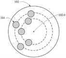
下面将描述具有微环境原位实时感知功能的介入针100的各种实施例。如图7所示(为了清楚起见,未示出工作通道102-4),在一些实施例中,介入针100还可以替代地或附加地包括一组或多组感测光纤106,所述一组或多组感测光纤106布置在针体102中并且沿针体102的中心轴线102-0纵向地延伸,使得所述一组或多组感测光纤106的前光纤端面106-1位于针体102的前端面102-1处,以便与活体内部的微环境直接接触。所述一组或多组感测光纤106中的每组感测光纤106可以用于感测活体内部的微环境的相应一种参数。每组感测光纤106中的每根感测光纤可以包括位于其前光纤端面处的具有光致发光材料的探头,所述光致发光材料被配置为具有随所述相应一种参数的变化而变化的发射光谱。所述一组或多组感测光纤106中的每组感测光纤106中的每根感测光纤可以被配置为朝向探头的光致发光材料传输激发光并接收来自光致发光材料的发射光,以便基于光致发光材料的发射光确定活体内部的微环境的相应一种参数。在一些实施例中,所述一组或多组感测光纤106中的每组感测光纤106可以各自关于针体102的中心轴线102-0对称地布置在针体102中。感测光纤的对称布置可以有利于分析微环境的参数的分布情况。在一些示例中,所述一组或多组感测光纤106可以各自旋转对称地分布于相应一个或多个同心圆上。在一些示例中,所述一组或多组感测光纤106中的两组或更多组感测光纤106可以分布于同一圆上。在一些实施例中,所述一组或多组感测光纤106可以与所述至少一个成像光纤束104分布于同一圆(如图7中的虚线所指示的)上,或分布于不同的同心圆上。感测光纤例如可以是一根光纤,其相比于成像光纤束可以细很多。Various embodiments of the
在一些实施例中,所述一组或多组感测光纤106可以包括以下中的一者或多者:第一组感测光纤,包括用于感测活体内部的微环境的温度的一根或多根第一感测光纤,第一组感测光纤中的每根第一感测光纤的探头具有被配置为具有随温度的变化而变化的发射光谱的第一光致发光材料;第二组感测光纤,包括用于感测活体内部的微环境的氧气浓度的一根或多根第二感测光纤,第二组感测光纤中的每根第二感测光纤的探头具有被配置为具有随氧气浓度的变化而变化的发射光谱的第二光致发光材料;以及第三组感测光纤,包括用于感测活体内部的微环境的酸碱度的一根或多根第三感测光纤,第三组感测光纤中的每根第三感测光纤的探头具有被配置为具有随酸碱度的变化而变化的发射光谱的第三光致发光材料。例如,参考图7,介入针100可以包括用于感测温度的第一组感测光纤1061a、用于感测氧气浓度的第二组感测光纤1062a、以及用于感测酸碱度的第三组感测光纤1063a。虽然图7中将每组感测光纤图示为各自包括一根感测光纤,但这仅仅是示例性的而非限制性的,每组感测光纤可以包括任意合适数量的感测光纤。当每组感测光纤包括分布在不同位置处的多根感测光纤时,有助于确定所述相应一种参数的分布情况。作为非限制性示例,第一光致发光材料可以包括Er3+掺杂的稀土上转换纳米粒子(如图9A所示,核心为Er3+掺杂的稀土纳米粒子,外层包覆壳层增强发光性能,形成核壳结构的NaYF4:Yb,Er@NaLuF4上转换纳米粒子;例如,可以经由第一感测光纤向其传输980nm的激发光,然后基于其发射光谱在525nm和545nm处的信号强度的比值的变化确定微环境中温度的变化),第二光致发光材料可以包括苯并卟啉类金属配合物(如图9B所示,例如,可以经由第二感测光纤向其传输635nm的激发光,然后基于其发射强度的变化确定微环境中氧气浓度的变化),并且第三光致发光材料可以包括多甲川花菁染料衍生物(如图9C所示,例如,可以经由第三感测光纤分别向其传输635nm的激发光和680nm的激发光,然后基于两种激发光条件下的发射强度的比值的变化确定酸碱度的变化)。参考图8,感测光纤106可以包括前光纤端面106-1和后光纤端面106-2,探头106-3形成于前光纤端面106-1上。例如,可以将光致发光材料与高分子基质材料预混后加入到圆柱形中空模具中固化成形得到探头,然后将探头融合组装在光纤的一端以得到感测光纤106。高分子基质材料例如可以包括聚甲基丙烯酸、聚乙烯亚胺、聚乙烯醇等,这些高分子材料具有较好的生物相容性,并且能与光纤有机融合,形成薄层对光纤表面进行改性,实现生物功能化。本公开所制备的感测光纤106可以具有优秀的检测性能指标,例如可以实现优于±1摄氏度的温度检测、优于±1%的氧气浓度检测、优于±0.1的酸碱度检测。In some embodiments, the one or more sets of
通过这些感测光纤106,可以原位实时获知针体102的前端面所在的活体局部微环境的多种参数的状态及分布情况,由此有利于指导医生即时做出可靠的诊断和治疗决策。例如,当发现氧气浓度过低时,医生不能用光动力疗法处置肿瘤,而需要改用其他疗法。Through these sensing
在一些实施例中,介入针100还可以包括光纤接口(未示出),该光纤接口可以设置在针体102的后端面102-2上或者在针体102的侧面的靠近后端面102-2的部分上。例如,针体102的所有光纤(照明光纤103、成像光纤束104、导航光纤束105、感测光纤106)的后光纤端面可以按预定规律布置在光纤接口处。例如,所有后光纤端面可以以阵列布置在光纤接口处。利用这样的布置,可以方便地通过对光纤接口进行成像以检测来自每个后光纤端面的信号,也可以方便地将期望的光耦合进每个后光纤端面中。在一些示例中,可以在光纤接口处将用于发射光的光纤的后光纤端面布置在一起,并将用于接收光的光纤的后光纤端面布置在一起,以便向介入针100的光纤输入光和从介入针100的光纤输出光。在一些示例中,介入针100可以包括设置有用于发射光的光纤的后光纤端面的第一光纤接口和设置有用于接收光的光纤的后光纤端面的第二光纤接口。可以利用光纤连接器、光缆等合适的光学传导部件将光纤接口光学耦接到活体外部的光源装置和检测装置。In some embodiments, the
返回参考图2,在一些实施例中,介入针100还可以包括可移除地设置于针体102的工作通道102-4内的内针110。内针110可以由任何合适的材料构成,例如可以由生物医用金属材料构成,包括但不限于不锈钢、合成纤维、碳纤维、钛合金、金、银等中的一种或多种。内针110可以由与针体102相同的材料形成。内针110可操作以在针体102被导航到目标部位处或附近时进入到目标部位内部。一般来讲,针体102可以在移动到目标部位附近2mm左右的位置时停止移动,然后通过推送内针110来使内针110介入目标部位内部。由于介入针100的工作通道102-4的偏心布置使得工作通道102-4可以提供更大的操作空间,因此内针110在工作通道102-4内可以具有更大的操作自由度,例如不仅可以实现线性运动,还可以实现旋转、摆动等非线性运动,从而允许医生控制内针110进行复杂多样化的操作。Referring back to FIG. 2 , in some embodiments, the
内针110可以类似于以上描述的关于针体102的各种实施例进行配置。考虑到实际临床需求以及在功能上与针体102互补等方面的因素,内针110的设计也可以与针体102存在一些差异。例如,在一方面,考虑到内针110与针体102形成嵌套结构,当利用针体102中的成像光纤束104和/或导航光纤束105确定好针体102的进针方向时,内针110的进针方向也基本上相应确定了,因而可以不在内针110上额外布置导航光纤束以用于内针110的导航定位;在另一方面,针对不同的诊疗模式,内针110可以被设计用于实现不同的功能。下面将结合图10、图11、图12A及图12B介绍几种示例内针。The
在一些实施例中,如图10所示,内针110可以包括布置在内针110中的一个或多个成像光纤束112,所述一个或多个成像光纤束112沿内针110的中心轴线110-0纵向地延伸并且具有位于内针110的前端面110-1处或附近的前光纤端面112-1。在一些示例中,所述一个或多个成像光纤束112中的每个成像光纤束112可以在其前光纤端面112-1处附接有与该成像光纤束112尺寸相当的物镜、例如鱼眼透镜。所述一个或多个成像光纤束112可以被配置为朝向活体内的目标部位发射成像探测光并接收来自目标部位的成像响应光,以便基于所述成像响应光对所述目标部位成像。成像响应光可以是源自成像探测光的反射光(例如直接成像)或发射光(例如荧光成像)。这样的内针110可以被称为成像内针。成像内针110的成像光纤束可以不具有传感功能,而仅仅用于实时原位成像。成像光纤束112可以包括成束的多根光纤,其可以比前述感测光纤106更粗但比成像光纤束104和/或导航光纤束105更细。可以在成像内针110中使用可商购的成像光纤束112。在一些实施例中,成像内针110的成像光纤束112例如可以是近红外成像光纤束,成像探测光例如可以包括波长为1064nm的光。可以理解,其他波长范围的成像探测光也是可行的。成像内针110例如可以是基于22G(国际通用标准针头规格)无创针改造的,其采用广角视网膜技术以及光束整形技术对目标部位进行光学重构成像,可用于超精细区域的实时组织微结构成像。在一些实施例中,每个成像光纤束112可以被配置为单独地朝向活体内的目标部位发射成像探测光并接收来自目标部位的成像响应光,即每个成像光纤束兼具光发射与光接收功能。在一些实施例中,所述一个或多个成像光纤束112中的一部分成像光纤束112可以被配置为朝向活体内的目标部位发射成像探测光而另一部分成像光纤束可以被配置为接收来自目标部位的成像响应光,即光发射功能与光接收功能由不同的成像光纤束执行。可以以任何合适的方式布置这些成像光纤束112,例如可以以阵列布置,如图10所示。In some embodiments, as shown in FIG. 10 , the
通过设置成像内针110,介入针100可以通过使成像内针110介入目标部位内部并利用设置在成像内针110中的成像光纤束112对目标部位内部成像以获得目标部位的深层次的特征。By positioning the imaging
在一些实施例中,如图11所示,内针110可以包括布置在内针110中的一组或多组感测光纤116,所述一组或多组感测光纤116沿内针110的中心轴线110-0纵向地延伸并且具有位于内针110的前端面110-1处或附近的前光纤端面116-1。所述一组或多组感测光纤116中的每组感测光纤116可以用于感测目标部位内部的微环境的相应一种参数。每组感测光纤116中的每根感测光纤可以包括位于其前光纤端面116-1处的具有光致发光材料的探头,所述光致发光材料可以被配置为具有随所述相应一种参数的变化而变化的发射光谱。所述一组或多组感测光纤116中的每组感测光纤中的每根感测光纤可以被配置为朝向探头的光致发光材料传输激发光并接收来自所述光致发光材料的发射光,以便基于所述光致发光材料的发射光确定目标部位内部的微环境的所述相应一种参数。布置在内针110中的感测光纤116可以类似于前述布置在针体102中的感测光纤106,在此可以不多赘述。这样的内针110可以被称为介入内针。由于针体102通常不进入目标部位内部,因而布置在针体102中的感测光纤106无法感测目标部位内部的微环境的参数。而介入内针110可以刺入目标部位内,所以可以用布置在介入内针110中的感测光纤116来原位实时感测目标部位内部的局部微环境的参数。在一些实施例中,例如参考图11,所述一组或多组感测光纤116可以包括以下中的一者或多者:第一组感测光纤,包括用于感测所述目标部位内部的微环境的温度的一根或多根第一感测光纤1161a-1161d,所述第一组感测光纤中的每根第一感测光纤的探头具有被配置为具有随温度的变化而变化的发射光谱的第一光致发光材料;第二组感测光纤,包括用于感测所述目标部位内部的微环境的氧气浓度的一根或多根第二感测光纤1162a、1162b,所述第二组感测光纤中的每根第二感测光纤的探头具有被配置为具有随氧气浓度的变化而变化的发射光谱的第二光致发光材料;以及第三组感测光纤,包括用于感测所述目标部位内部的微环境的酸碱度的一根或多根第三感测光纤1163a、1163b,所述第三组感测光纤中的每根第三感测光纤的探头具有被配置为具有随酸碱度的变化而变化的发射光谱的第三光致发光材料。在一些示例中,介入内针110也可以基于22G无创针来改造,因而可以基于无创针的特性而在活体的多个位点布针,从而为研究微环境联动性或监测生理状态提供了工具基础。在一些实施例中,所述一组或多组感测光纤116中的每组感测光纤116可以各自关于介入内针110的中心轴线110-0对称地(例如,旋转对称地)布置在介入内针110中。感测光纤的对称布置可以有利于分析微环境的参数的分布情况。在一些实施例中,介入内针110还可以具有中空通道110-4,例如用于对所述目标部位注射化学消融药物(例如,酒精等),以进行化学消融。在一些示例中,中空通道110-4可以关于介入内针110的中心轴线110-0同心地布置,例如如图11所示。在一些示例中,中空通道110-4也可以关于介入内针110的中心轴线110-0偏心地布置。由此,能够优化介入内针110的组成部件的空间布局,从而在介入内针110的其他组成部件及其尺寸保持不变的情况下,偏心布置的中空通道110-4可以具有更大的横截面积,从而可以提供更大的操作空间。从另一个角度说,在中空通道110-4的横截面积保持不变的情况下,介入内针110可以被构造得更小,这有利于介入内针110的小型化设计。小型化的介入内针110在与介入针100的针体102一起使用时,一方面在工作通道102-4的横截面积保持不变的情况下可以具有更高的操作自由度,另一方面可以允许工作通道102-4乃至整个针体102被构造得更小。In some embodiments, as shown in FIG. 11 , the
在一些实施例中,内针110可以被配置用于对所述目标部位进行热消融。这样的内针可以被称为热消融内针。热消融内针110例如可以为射频消融针。由于在热消融内针的工作过程中温度分布监测十分重要,因而如图12A所示,热消融内针110可以包括布置在内针110中的一组或多组温度感测光纤1161,所述一组或多组温度感测光纤1161沿内针110的中心轴线110-0纵向地延伸。进一步参考图12B,所述一组或多组温度感测光纤1161中的每组温度感测光纤的前光纤端面1161-1位于内针110的从前端面110-1到后端面110-2之间的相应一个横截面(如点划线A、B、C、D、E、F所示)处。所述一组或多组温度感测光纤1161中的每组温度感测光纤可以用于感测所述目标部位内部的微环境的温度。每组温度感测光纤1161中的每根温度感测光纤1161可以包括位于其前光纤端面1161-1处的具有光致发光材料的探头,所述光致发光材料可以被配置为具有随温度的变化而变化的发射光谱。所述一组或多组温度感测光纤1161中的每组温度感测光纤中的每根温度感测光纤被配置为朝向所述探头的所述光致发光材料传输激发光并接收来自所述光致发光材料的发射光,以便基于所述光致发光材料的发射光确定所述目标部位内部的微环境的温度。可以基于所确定的温度控制热消融内针的输出功率,从而使目标部位的微环境温度稳定在期望温度附近。温度感测光纤1161可以类似于前述用于感测温度的第一感测光纤1061a,在此可以不再赘述。在一些实施例中,如果所述一组或多组温度感测光纤1161中的第一组温度感测光纤相对于所述一组或多组温度感测光纤1161中的第二组温度感测光纤更靠近所述内针的前端面,则第一组温度感测光纤的温度感测光纤密度可以大于第二组温度感测光纤的温度感测光纤密度。所述温度感测光纤密度是指一组温度感测光纤的数量与该组温度感测光纤的前光纤端面所在的内针横截面的面积之比。例如如图12B所示,横截面C处的温度感测光纤密度大于横截面D处的温度感测光纤密度。由于内针110的形成材料的导热性通常较好,因此温度感测光纤1161的前光纤端面不一定要暴露于内针110的表面,而是可以位于内针110内部。此外,热消融内针110也可以基于22G无创针来改造,由此可以在热消融过程中在多个重要位点布针,从而形成热消融温度监测圈,以指导热消融手术的高效展开。当监测发现某病灶达不到热消融的温度要求时,可以将热消融内针替换为之前关于图11描述的介入内针,并通过介入内针的中空通道注射酒精等来进行化学消融。In some embodiments, the
可以理解,以上结合图10、图11、图12A及图12B描述的仅仅是可与针体102组合使用的内针110的几种非限制性示例。可以根据实际需求基于本公开的任意实施例或其结合来设计内针110。内针110可以长于针体102,并且也可以在内针110的后端面110-2或在内针110的侧面的靠近后端面110-2的部分设置光纤接口,用于按预定规律布置内针110中的光纤的后光纤端面。It will be appreciated that the above descriptions in connection with FIGS. 10 , 11 , 12A, and 12B are only a few non-limiting examples of
根据本公开的各种实施例的用于硬式内窥镜的介入针,通过工作通道在针体中的偏心布置,能够优化介入针的组成部件的空间布局,从而有利于构建横截面积更大的工作通道或有利于介入针的小型化设计。而且根据本公开的各种实施例的用于硬式内窥镜的介入针本身可以具有光学成像功能,以直接作为硬式内窥镜的成像部分,从而避免了现有的用于成像的硬式内窥镜与用于介入诊疗操作的介入针的复杂组件的使用,并且可以保持介入针的进针方位与观察视野的良好一致性。此外,根据本公开的各种实施例的用于硬式内窥镜的介入针可以利用原位实时光学导航功能指导介入针的进针过程,还可以利用光致发光探头灵敏地原位实时监测并利用光纤高保真地提取活体内及目标部位内的微环境的温度、氧气浓度、酸碱度等参数的数值及分布情况,及时反馈诸如热疗、化疗等诊疗手段的治疗强度及效果,以便医生即时调整诊疗策略。而且,根据本公开的各种实施例的介入针的照明光纤、导航光纤束、成像光纤束和各种感测光纤均布置在针体或内针之内,因而可以利用介入针的介入通道进入活体内,并且受到介入针的保护,从而可以将微环境的细微变化所导致的光学信号传递到体外的分析设备,同时可以抵抗生物组织对光学信号的干扰。According to the interventional needle for a rigid endoscope according to various embodiments of the present disclosure, through the eccentric arrangement of the working channel in the needle body, the spatial layout of the components of the interventional needle can be optimized, thereby facilitating the construction of a larger cross-sectional area The working channel is convenient for the miniaturized design of the interventional needle. Moreover, the interventional needle for a rigid endoscope according to various embodiments of the present disclosure may itself have an optical imaging function to directly serve as the imaging part of the rigid endoscope, thereby avoiding the existing rigid endoscope for imaging. The use of a mirror and a complex assembly of an interventional needle for interventional diagnosis and treatment operations can keep the needle insertion orientation of the interventional needle in good consistency with the observation field. In addition, the interventional needle for a rigid endoscope according to various embodiments of the present disclosure can use the in-situ real-time optical navigation function to guide the needle insertion process of the interventional needle, and can also use a photoluminescence probe to sensitively monitor and monitor in-situ real-time and The value and distribution of parameters such as temperature, oxygen concentration, pH and other parameters of the microenvironment in vivo and in the target site are extracted with high fidelity by using optical fiber, and the treatment intensity and effect of diagnosis and treatment methods such as hyperthermia and chemotherapy can be fed back in time, so that doctors can adjust immediately. diagnosis and treatment strategies. Moreover, the illumination fiber, navigation fiber bundle, imaging fiber bundle, and various sensing fibers of the interventional needle according to various embodiments of the present disclosure are all arranged within the needle body or inner needle, and thus can be accessed using the interventional channel of the interventional needle In vivo, and protected by the interventional needle, the optical signal caused by the subtle changes in the microenvironment can be transmitted to the analysis equipment in vitro, and the interference of the optical signal by the biological tissue can be resisted.
在另一方面,本公开还提供了一种硬式内窥镜,其可以包括根据本公开的上述任一实施例所述的介入针,在此不再赘述。由于根据本公开的各种实施例的介入针的原位成像能力和原位监测能力允许对目标部位的原位诊断和治疗,因此根据本公开的各种实施例的介入针所需的手术空间较小,使得包括根据本公开的各种实施例的介入针的硬式内窥镜在实施介入诊疗前不再需要向病患体内充气以扩张体腔,这有利地简化了手术流程,降低了手术成本,提高了病患舒适度。In another aspect, the present disclosure also provides a rigid endoscope, which may include the intervention needle according to any one of the above embodiments of the present disclosure, which will not be repeated here. Since the in-situ imaging capabilities and in-situ monitoring capabilities of the interventional needles according to various embodiments of the present disclosure allow for in-situ diagnosis and treatment of target sites, the surgical space required by the interventional needles according to various embodiments of the present disclosure Small, so that the rigid endoscope including the interventional needle according to various embodiments of the present disclosure no longer needs to be inflated into the patient to expand the body cavity before performing interventional diagnosis and treatment, which advantageously simplifies the surgical procedure and reduces the surgical cost , improve patient comfort.
在说明书及权利要求中的词语“左”、“右”、“前”、“后”、“顶”、“底”、“上”、“下”、“高”、“低”等,如果存在的话,用于描述性的目的而并不一定用于描述不变的相对位置。应当理解,这样使用的词语在适当的情况下是可互换的,使得在此所描述的本公开的实施例,例如,能够在与在此所示出的或另外描述的那些取向不同的其它取向上操作。例如,在附图中的装置倒转时,原先描述为在其它特征“之上”的特征,此时可以描述为在其它特征“之下”。装置还可以以其它方式定向(旋转90度或在其它方位),此时将相应地解释相对空间关系。The words "left", "right", "front", "rear", "top", "bottom", "top", "bottom", "high", "low", etc. in the description and claims, if If present, it is used for descriptive purposes and not necessarily to describe an invariant relative position. It is to be understood that the terms so used are interchangeable under appropriate circumstances such that the embodiments of the disclosure described herein are, for example, capable of other orientations than those illustrated or otherwise described herein. Orientation to operate. For example, when the device in the figures is turned over, features previously described as "above" other features may now be described as "below" the other features. The device may also be otherwise oriented (rotated 90 degrees or at other orientations) in which case the relative spatial relationships will be interpreted accordingly.
在说明书及权利要求中,称一个元件位于另一元件“之上”、“附接”至另一元件、“连接”至另一元件、“耦合”至另一元件、“耦接”至另一元件、或“接触”另一元件等时,该元件可以直接位于另一元件之上、直接附接至另一元件、直接连接至另一元件、直接耦合至另一元件、直接耦接至另一元件或直接接触另一元件,或者可以存在一个或多个中间元件。相对照的是,称一个元件“直接”位于另一元件“之上”、“直接附接”至另一元件、“直接连接”至另一元件、“直接耦合”至另一元件、“直接耦接”至另一元件或“直接接触”另一元件时,将不存在中间元件。在说明书及权利要求中,一个特征布置成与另一特征“相邻”,可以指一个特征具有与相邻特征重叠的部分或者位于相邻特征上方或下方的部分。In the specification and claims, an element is referred to as being "on", "attached" to, "connected" to, "coupled" to, "coupled" to another element When an element, or "contacts" another element, etc., the element can be directly on the other element, directly attached to the other element, directly connected to the other element, directly coupled to the other element, directly coupled to the other element The other element either directly contacts the other element, or one or more intervening elements may be present. In contrast, an element is referred to as being "directly on" another element, "directly attached" to another element, "directly connected" to another element, "directly coupled" to another element, "directly coupled" to another element When coupled to" or "directly in contact with" another element, there will be no intervening elements present. In the specification and claims, a feature is arranged "adjacent" to another feature, which can mean that a feature has a portion that overlaps an adjacent feature or a portion that is above or below an adjacent feature.
如在此所使用的,词语“示例性的”意指“用作示例、实例或说明”,而不是作为将被精确复制的“模型”。在此示例性描述的任意实现方式并不一定要被解释为比其它实现方式优选的或有利的。而且,本公开不受在技术领域、背景技术、发明内容或具体实施方式中所给出的任何所表述的或所暗示的理论所限定。As used herein, the word "exemplary" means "serving as an example, instance, or illustration" rather than as a "model" to be exactly reproduced. Any implementation illustratively described herein is not necessarily to be construed as preferred or advantageous over other implementations. Furthermore, the present disclosure is not to be bound by any expressed or implied theory presented in the technical field, background, brief summary or detailed description.
如在此所使用的,词语“基本上”意指包含由设计或制造的缺陷、器件或元件的容差、环境影响和/或其它因素所致的任意微小的变化。词语“基本上”还允许由寄生效应、噪声以及可能存在于实际的实现方式中的其它实际考虑因素所致的与完美的或理想的情形之间的差异。As used herein, the word "substantially" is meant to encompass any minor variation due to design or manufacturing imperfections, tolerances of devices or elements, environmental influences, and/or other factors. The word "substantially" also allows for differences from a perfect or ideal situation due to parasitics, noise, and other practical considerations that may exist in an actual implementation.
另外,仅仅为了参考的目的,还可以在本文中使用“第一”、“第二”等类似术语,并且因而并非意图限定。例如,除非上下文明确指出,否则涉及结构或元件的词语“第一”、“第二”和其它此类数字词语并没有暗示顺序或次序。Also, terms like "first," "second," and the like may also be used herein for reference purposes only, and are thus not intended to be limiting. For example, the terms "first," "second," and other such numerical terms referring to structures or elements do not imply a sequence or order unless the context clearly dictates otherwise.
还应理解,“包括/包含”一词在本文中使用时,说明存在所指出的特征、整体、步骤、操作、单元和/或组件,但是并不排除存在或增加一个或多个其它特征、整体、步骤、操作、单元和/或组件以及/或者它们的组合。It should also be understood that the term "comprising/comprising" when used herein indicates the presence of the indicated feature, integer, step, operation, unit and/or component, but does not preclude the presence or addition of one or more other features, Entities, steps, operations, units and/or components and/or combinations thereof.
在本公开中,术语“提供”从广义上用于涵盖获得对象的所有方式,因此“提供某对象”包括但不限于“购买”、“制备/制造”、“布置/设置”、“安装/装配”、和/或“订购”对象等。In this disclosure, the term "providing" is used broadly to encompass all ways of obtaining an object, thus "providing something" includes, but is not limited to, "purchasing," "preparing/manufacturing," "arranging/arranging," "installing/ Assembly", and/or "Order" objects, etc.
如本文所使用的,术语“和/或”包括相关联的列出项目中的一个或多个的任何和所有组合。本文中使用的术语只是出于描述特定实施例的目的,并不旨在限制本公开。如本文中使用的,单数形式“一”、“一个”和“该”也旨在包括复数形式,除非上下文另外清楚指示。As used herein, the term "and/or" includes any and all combinations of one or more of the associated listed items. The terminology used herein is for the purpose of describing particular embodiments only and is not intended to limit the present disclosure. As used herein, the singular forms "a," "an," and "the" are intended to include the plural forms as well, unless the context clearly dictates otherwise.
本领域技术人员应当意识到,在上述操作之间的边界仅仅是说明性的。多个操作可以结合成单个操作,单个操作可以分布于附加的操作中,并且操作可以在时间上至少部分重叠地执行。而且,另选的实施例可以包括特定操作的多个实例,并且在其它各种实施例中可以改变操作顺序。但是,其它的修改、变化和替换同样是可能的。可以以任何方式和/或与其它实施例的方面或元件相结合地组合以上公开的所有实施例的方面和元件,以提供多个附加实施例。因此,本说明书和附图应当被看作是说明性的,而非限制性的。Those skilled in the art will appreciate that the boundaries between the operations described above are merely illustrative. Multiple operations may be combined into a single operation, a single operation may be distributed among additional operations, and operations may be performed at least partially overlapping in time. Furthermore, alternative embodiments may include multiple instances of a particular operation, and the order of operations may be changed in other various embodiments. However, other modifications, changes and substitutions are equally possible. Aspects and elements of all the embodiments disclosed above may be combined in any manner and/or in combination with aspects or elements of other embodiments to provide a number of additional embodiments. Accordingly, the specification and drawings are to be regarded in an illustrative rather than a restrictive sense.
虽然已经通过示例对本公开的一些特定实施例进行了详细说明,但是本领域的技术人员应该理解,以上示例仅是为了进行说明,而不是为了限制本公开的范围。在此公开的各实施例可以任意组合,而不脱离本公开的精神和范围。本领域的技术人员还应理解,可以对实施例进行多种修改而不脱离本公开的范围和精神。本公开的范围由所附权利要求来限定。While some specific embodiments of the present disclosure have been described in detail by way of examples, those skilled in the art will appreciate that the above examples are provided for illustration only, and are not intended to limit the scope of the present disclosure. The various embodiments disclosed herein may be combined arbitrarily without departing from the spirit and scope of the present disclosure. It will also be understood by those skilled in the art that various modifications may be made to the embodiments without departing from the scope and spirit of the present disclosure. The scope of the present disclosure is defined by the appended claims.
Claims (23)
Priority Applications (1)
| Application Number | Priority Date | Filing Date | Title |
|---|---|---|---|
| CN202210735925.5ACN114931348A (en) | 2022-06-27 | 2022-06-27 | Interventional needles and rigid endoscopes for rigid endoscopes |
Applications Claiming Priority (1)
| Application Number | Priority Date | Filing Date | Title |
|---|---|---|---|
| CN202210735925.5ACN114931348A (en) | 2022-06-27 | 2022-06-27 | Interventional needles and rigid endoscopes for rigid endoscopes |
Publications (1)
| Publication Number | Publication Date |
|---|---|
| CN114931348Atrue CN114931348A (en) | 2022-08-23 |
Family
ID=82867887
Family Applications (1)
| Application Number | Title | Priority Date | Filing Date |
|---|---|---|---|
| CN202210735925.5APendingCN114931348A (en) | 2022-06-27 | 2022-06-27 | Interventional needles and rigid endoscopes for rigid endoscopes |
Country Status (1)
| Country | Link |
|---|---|
| CN (1) | CN114931348A (en) |
Citations (4)
| Publication number | Priority date | Publication date | Assignee | Title |
|---|---|---|---|---|
| CN101495025A (en)* | 2005-04-15 | 2009-07-29 | 塞基森斯公司 | Surgical instrument with sensor for detecting tissue properties, and system using said instrument |
| CN108066001A (en)* | 2016-11-10 | 2018-05-25 | 奥斯奥鹏外科产品股份公司 | Carry the working lens of inductive probe |
| CN109512473A (en)* | 2017-09-20 | 2019-03-26 | 史军 | Medical Devices with visual puncturing device |
| CN113453606A (en)* | 2018-12-20 | 2021-09-28 | 阿克拉伦特公司 | Endoscope with dual image sensor |
- 2022
- 2022-06-27CNCN202210735925.5Apatent/CN114931348A/enactivePending
Patent Citations (4)
| Publication number | Priority date | Publication date | Assignee | Title |
|---|---|---|---|---|
| CN101495025A (en)* | 2005-04-15 | 2009-07-29 | 塞基森斯公司 | Surgical instrument with sensor for detecting tissue properties, and system using said instrument |
| CN108066001A (en)* | 2016-11-10 | 2018-05-25 | 奥斯奥鹏外科产品股份公司 | Carry the working lens of inductive probe |
| CN109512473A (en)* | 2017-09-20 | 2019-03-26 | 史军 | Medical Devices with visual puncturing device |
| CN113453606A (en)* | 2018-12-20 | 2021-09-28 | 阿克拉伦特公司 | Endoscope with dual image sensor |
Similar Documents
| Publication | Publication Date | Title |
|---|---|---|
| US20210338121A1 (en) | Apparatus, systems and methods for determining tissue oxygenation | |
| US12419550B2 (en) | Apparatus, systems, and methods for mapping of tissue oxygenation | |
| US6246901B1 (en) | Detecting, localizing, and targeting internal sites in vivo using optical contrast agents | |
| US6594518B1 (en) | Device and method for classification of tissue | |
| RU2535611C2 (en) | Needle with integrated fibres in bevel cutting edges | |
| JP2014518118A (en) | Needle with optical fiber integrated into an elongated insert | |
| EP2358263A1 (en) | Needle with optical fibers | |
| WO2004016155A2 (en) | Apparatus for multifocal deposition and analysis and methods for its use | |
| CN219289407U (en) | Interventional needle for a flexible endoscope, flexible endoscope and flexible endoscope system | |
| CN114931348A (en) | Interventional needles and rigid endoscopes for rigid endoscopes | |
| CN219126267U (en) | Interventional needle for hard endoscope and hard endoscope | |
| CN115054186A (en) | Interventional needle for flexible endoscope, flexible endoscope and flexible endoscope system | |
| CN116584880A (en) | Integrated endoscopic probe for photodynamic diagnosis and treatment of digestive tract tumors based on optical multimodality | |
| CN218009895U (en) | Interventional needle | |
| NL2025324B1 (en) | A Surgical Tool, System and Method for Tissue Characterisation | |
| CN218739076U (en) | Interventional diagnosis and treatment system | |
| CN115040213A (en) | Interventional needle | |
| CN219021459U (en) | Interventional needle and interventional system | |
| KR102456893B1 (en) | Fluorescence diagnostic device and control method | |
| CN114931424A (en) | Interventional diagnosis and treatment system and using method thereof | |
| US20090270724A1 (en) | Scanned beam device and method using same which measures the reflectance of patient tissue | |
| CN116234517A (en) | Spectroscopy system | |
| HK1249383B (en) | Apparatus, systems, and methods for mapping of tissue oxygenation |
Legal Events
| Date | Code | Title | Description |
|---|---|---|---|
| PB01 | Publication | ||
| PB01 | Publication | ||
| SE01 | Entry into force of request for substantive examination | ||
| SE01 | Entry into force of request for substantive examination |