CN114930387A - Ultrasound imaging method and system for identifying anatomical features of the spine - Google Patents
Ultrasound imaging method and system for identifying anatomical features of the spineDownload PDFInfo
- Publication number
- CN114930387A CN114930387ACN202080091818.2ACN202080091818ACN114930387ACN 114930387 ACN114930387 ACN 114930387ACN 202080091818 ACN202080091818 ACN 202080091818ACN 114930387 ACN114930387 ACN 114930387A
- Authority
- CN
- China
- Prior art keywords
- spine
- ultrasound image
- paramedian
- processor
- sagittal
- Prior art date
- Legal status (The legal status is an assumption and is not a legal conclusion. Google has not performed a legal analysis and makes no representation as to the accuracy of the status listed.)
- Pending
Links
Images


Classifications
- G—PHYSICS
- G06—COMPUTING OR CALCULATING; COUNTING
- G06V—IMAGE OR VIDEO RECOGNITION OR UNDERSTANDING
- G06V10/00—Arrangements for image or video recognition or understanding
- G06V10/70—Arrangements for image or video recognition or understanding using pattern recognition or machine learning
- G06V10/764—Arrangements for image or video recognition or understanding using pattern recognition or machine learning using classification, e.g. of video objects
- G—PHYSICS
- G06—COMPUTING OR CALCULATING; COUNTING
- G06T—IMAGE DATA PROCESSING OR GENERATION, IN GENERAL
- G06T7/00—Image analysis
- G06T7/70—Determining position or orientation of objects or cameras
- G06T7/73—Determining position or orientation of objects or cameras using feature-based methods
- G06T7/74—Determining position or orientation of objects or cameras using feature-based methods involving reference images or patches
- A—HUMAN NECESSITIES
- A61—MEDICAL OR VETERINARY SCIENCE; HYGIENE
- A61B—DIAGNOSIS; SURGERY; IDENTIFICATION
- A61B8/00—Diagnosis using ultrasonic, sonic or infrasonic waves
- A61B8/08—Clinical applications
- A61B8/0833—Clinical applications involving detecting or locating foreign bodies or organic structures
- A61B8/085—Clinical applications involving detecting or locating foreign bodies or organic structures for locating body or organic structures, e.g. tumours, calculi, blood vessels, nodules
- A—HUMAN NECESSITIES
- A61—MEDICAL OR VETERINARY SCIENCE; HYGIENE
- A61B—DIAGNOSIS; SURGERY; IDENTIFICATION
- A61B8/00—Diagnosis using ultrasonic, sonic or infrasonic waves
- A61B8/08—Clinical applications
- A61B8/0875—Clinical applications for diagnosis of bone
- A—HUMAN NECESSITIES
- A61—MEDICAL OR VETERINARY SCIENCE; HYGIENE
- A61B—DIAGNOSIS; SURGERY; IDENTIFICATION
- A61B8/00—Diagnosis using ultrasonic, sonic or infrasonic waves
- A61B8/44—Constructional features of the ultrasonic, sonic or infrasonic diagnostic device
- A61B8/4444—Constructional features of the ultrasonic, sonic or infrasonic diagnostic device related to the probe
- A—HUMAN NECESSITIES
- A61—MEDICAL OR VETERINARY SCIENCE; HYGIENE
- A61B—DIAGNOSIS; SURGERY; IDENTIFICATION
- A61B8/00—Diagnosis using ultrasonic, sonic or infrasonic waves
- A61B8/52—Devices using data or image processing specially adapted for diagnosis using ultrasonic, sonic or infrasonic waves
- A61B8/5215—Devices using data or image processing specially adapted for diagnosis using ultrasonic, sonic or infrasonic waves involving processing of medical diagnostic data
- A61B8/5223—Devices using data or image processing specially adapted for diagnosis using ultrasonic, sonic or infrasonic waves involving processing of medical diagnostic data for extracting a diagnostic or physiological parameter from medical diagnostic data
- A—HUMAN NECESSITIES
- A61—MEDICAL OR VETERINARY SCIENCE; HYGIENE
- A61B—DIAGNOSIS; SURGERY; IDENTIFICATION
- A61B8/00—Diagnosis using ultrasonic, sonic or infrasonic waves
- A61B8/52—Devices using data or image processing specially adapted for diagnosis using ultrasonic, sonic or infrasonic waves
- A61B8/5215—Devices using data or image processing specially adapted for diagnosis using ultrasonic, sonic or infrasonic waves involving processing of medical diagnostic data
- A61B8/5238—Devices using data or image processing specially adapted for diagnosis using ultrasonic, sonic or infrasonic waves involving processing of medical diagnostic data for combining image data of patient, e.g. merging several images from different acquisition modes into one image
- A61B8/5246—Devices using data or image processing specially adapted for diagnosis using ultrasonic, sonic or infrasonic waves involving processing of medical diagnostic data for combining image data of patient, e.g. merging several images from different acquisition modes into one image combining images from the same or different imaging techniques, e.g. color Doppler and B-mode
- G—PHYSICS
- G06—COMPUTING OR CALCULATING; COUNTING
- G06T—IMAGE DATA PROCESSING OR GENERATION, IN GENERAL
- G06T7/00—Image analysis
- G06T7/20—Analysis of motion
- G06T7/246—Analysis of motion using feature-based methods, e.g. the tracking of corners or segments
- G06T7/248—Analysis of motion using feature-based methods, e.g. the tracking of corners or segments involving reference images or patches
- G—PHYSICS
- G06—COMPUTING OR CALCULATING; COUNTING
- G06T—IMAGE DATA PROCESSING OR GENERATION, IN GENERAL
- G06T7/00—Image analysis
- G06T7/60—Analysis of geometric attributes
- G06T7/62—Analysis of geometric attributes of area, perimeter, diameter or volume
- G—PHYSICS
- G06—COMPUTING OR CALCULATING; COUNTING
- G06T—IMAGE DATA PROCESSING OR GENERATION, IN GENERAL
- G06T7/00—Image analysis
- G06T7/60—Analysis of geometric attributes
- G06T7/66—Analysis of geometric attributes of image moments or centre of gravity
- G—PHYSICS
- G06—COMPUTING OR CALCULATING; COUNTING
- G06V—IMAGE OR VIDEO RECOGNITION OR UNDERSTANDING
- G06V10/00—Arrangements for image or video recognition or understanding
- G06V10/10—Image acquisition
- G06V10/16—Image acquisition using multiple overlapping images; Image stitching
- G—PHYSICS
- G06—COMPUTING OR CALCULATING; COUNTING
- G06V—IMAGE OR VIDEO RECOGNITION OR UNDERSTANDING
- G06V10/00—Arrangements for image or video recognition or understanding
- G06V10/40—Extraction of image or video features
- G06V10/44—Local feature extraction by analysis of parts of the pattern, e.g. by detecting edges, contours, loops, corners, strokes or intersections; Connectivity analysis, e.g. of connected components
- G—PHYSICS
- G06—COMPUTING OR CALCULATING; COUNTING
- G06V—IMAGE OR VIDEO RECOGNITION OR UNDERSTANDING
- G06V10/00—Arrangements for image or video recognition or understanding
- G06V10/70—Arrangements for image or video recognition or understanding using pattern recognition or machine learning
- G06V10/74—Image or video pattern matching; Proximity measures in feature spaces
- G06V10/75—Organisation of the matching processes, e.g. simultaneous or sequential comparisons of image or video features; Coarse-fine approaches, e.g. multi-scale approaches; using context analysis; Selection of dictionaries
- G06V10/751—Comparing pixel values or logical combinations thereof, or feature values having positional relevance, e.g. template matching
- A—HUMAN NECESSITIES
- A61—MEDICAL OR VETERINARY SCIENCE; HYGIENE
- A61B—DIAGNOSIS; SURGERY; IDENTIFICATION
- A61B17/00—Surgical instruments, devices or methods
- A61B17/34—Trocars; Puncturing needles
- A61B17/3403—Needle locating or guiding means
- A61B2017/3413—Needle locating or guiding means guided by ultrasound
- G—PHYSICS
- G06—COMPUTING OR CALCULATING; COUNTING
- G06N—COMPUTING ARRANGEMENTS BASED ON SPECIFIC COMPUTATIONAL MODELS
- G06N20/00—Machine learning
- G06N20/10—Machine learning using kernel methods, e.g. support vector machines [SVM]
- G—PHYSICS
- G06—COMPUTING OR CALCULATING; COUNTING
- G06T—IMAGE DATA PROCESSING OR GENERATION, IN GENERAL
- G06T2200/00—Indexing scheme for image data processing or generation, in general
- G06T2200/24—Indexing scheme for image data processing or generation, in general involving graphical user interfaces [GUIs]
- G—PHYSICS
- G06—COMPUTING OR CALCULATING; COUNTING
- G06T—IMAGE DATA PROCESSING OR GENERATION, IN GENERAL
- G06T2207/00—Indexing scheme for image analysis or image enhancement
- G06T2207/10—Image acquisition modality
- G06T2207/10016—Video; Image sequence
- G—PHYSICS
- G06—COMPUTING OR CALCULATING; COUNTING
- G06T—IMAGE DATA PROCESSING OR GENERATION, IN GENERAL
- G06T2207/00—Indexing scheme for image analysis or image enhancement
- G06T2207/10—Image acquisition modality
- G06T2207/10132—Ultrasound image
- G—PHYSICS
- G06—COMPUTING OR CALCULATING; COUNTING
- G06T—IMAGE DATA PROCESSING OR GENERATION, IN GENERAL
- G06T2207/00—Indexing scheme for image analysis or image enhancement
- G06T2207/30—Subject of image; Context of image processing
- G06T2207/30004—Biomedical image processing
- G06T2207/30008—Bone
- G06T2207/30012—Spine; Backbone
- G—PHYSICS
- G06—COMPUTING OR CALCULATING; COUNTING
- G06T—IMAGE DATA PROCESSING OR GENERATION, IN GENERAL
- G06T2207/00—Indexing scheme for image analysis or image enhancement
- G06T2207/30—Subject of image; Context of image processing
- G06T2207/30172—Centreline of tubular or elongated structure
Landscapes
- Engineering & Computer Science (AREA)
- Health & Medical Sciences (AREA)
- Life Sciences & Earth Sciences (AREA)
- Physics & Mathematics (AREA)
- Theoretical Computer Science (AREA)
- Computer Vision & Pattern Recognition (AREA)
- General Physics & Mathematics (AREA)
- General Health & Medical Sciences (AREA)
- Medical Informatics (AREA)
- Radiology & Medical Imaging (AREA)
- Biomedical Technology (AREA)
- Heart & Thoracic Surgery (AREA)
- Pathology (AREA)
- Molecular Biology (AREA)
- Surgery (AREA)
- Animal Behavior & Ethology (AREA)
- Nuclear Medicine, Radiotherapy & Molecular Imaging (AREA)
- Public Health (AREA)
- Veterinary Medicine (AREA)
- Biophysics (AREA)
- Multimedia (AREA)
- Evolutionary Computation (AREA)
- Artificial Intelligence (AREA)
- Computing Systems (AREA)
- Databases & Information Systems (AREA)
- Software Systems (AREA)
- Geometry (AREA)
- Orthopedic Medicine & Surgery (AREA)
- Rheumatology (AREA)
- Physiology (AREA)
- Vascular Medicine (AREA)
- Ultra Sonic Daignosis Equipment (AREA)
Abstract
Translated fromChinese
Description
Translated fromChinese技术领域technical field
本公开涉及一种用于识别脊柱的解剖特征的超声成像方法和系统。The present disclosure relates to an ultrasound imaging method and system for identifying anatomical features of the spine.
背景技术Background technique
神经轴手术通常在广泛的治疗和诊断指征下进行。神经轴手术的示例包括用于手术的神经轴麻醉、硬膜外分娩镇痛、硬膜外类固醇注射和腰椎穿刺。为了执行神经轴手术,需要确定在脊柱的适当脊柱节段处的针插入位置和到脊柱的神经轴间隙(space)的路径。Nerve axis surgery is usually performed under a wide range of therapeutic and diagnostic indications. Examples of nerve axis procedures include nerve axis anesthesia for surgery, epidural labor pain relief, epidural steroid injections, and lumbar puncture. In order to perform nerve axis surgery, the needle insertion location at the appropriate spinal segment of the spine and the path to the nerve axis space of the spine need to be determined.
目前,通常使用用于识别针插入的位置和用于确定到神经轴间隙的路径的盲触诊标志(landmark)方法。然而,这种方法是高度不准确的,因为它严重依赖于执行神经轴手术的从业者的相关技能和经验。如果对肥胖患者或背部受伤的患者执行盲触诊标志方法,则盲触诊标志方法可能更复杂,因为在这些情况下不能可靠地触诊解剖标志。因此,盲触诊标志方法可能导致多次插入尝试,从而使患者经历不必要的痛苦并增加并发症(诸如患者的脊髓损伤)的风险。Currently, blind palpation landmark methods for identifying the location of needle insertion and for determining the path to the axonal space are commonly used. However, this method is highly inaccurate as it relies heavily on the relevant skills and experience of the practitioner performing the nerve axis surgery. The blind palpation landmark method may be more complicated if performed on obese patients or patients with back injuries, as anatomical landmarks cannot be palpated reliably in these cases. As a result, the blind palpation of the landmark method may result in multiple insertion attempts, exposing the patient to unnecessary pain and increasing the risk of complications such as spinal cord injury to the patient.
鉴于上述情况,神经轴超声检查法已变得普遍用于神经轴间隙识别,因为其被证明是安全且有效的方法。随着其越来越多地用作体检的辅助手段,硬膜外和脊柱给药以及腰椎穿刺的总成功率得到提高,并且注射尝试的次数减少。尽管如此,在许多常规超声系统中,由离轴反射产生伪影。此外,二维超声图像难以解释,并且需要有经验的从业者的帮助来利用这些图像。此外,可能出现不一致,因为对这些超声图像的解释高度依赖于从业者的技能。In light of the above, axonal sonography has become popular for axonal gap identification as it has been shown to be a safe and effective method. With its increasing use as an adjunct to physical examinations, the overall success rate of epidural and spinal administration and lumbar puncture has improved, and the number of injection attempts has decreased. Nonetheless, in many conventional ultrasound systems, artifacts arise from off-axis reflections. Furthermore, 2D ultrasound images are difficult to interpret, and the help of an experienced practitioner is required to utilize these images. Furthermore, inconsistencies can arise because the interpretation of these ultrasound images is highly dependent on the skill of the practitioner.
因此,期望提供一种用于识别脊柱的解剖特征的系统和方法,其解决上述问题和/或提供有用的替代方案。此外,结合附图和本公开的背景技术,从随后详细描述的说明书和所附权利要求中,其他期望的特征和特性将变得显而易见。Accordingly, it would be desirable to provide a system and method for identifying anatomical features of the spine that address the above problems and/or provide a useful alternative. Furthermore, other desirable features and characteristics will become apparent from the subsequent detailed description and the appended claims, taken in conjunction with the accompanying drawings and this background of the disclosure.
发明内容SUMMARY OF THE INVENTION
本申请的方面涉及一种用于识别脊柱的解剖特征的超声成像方法和系统。Aspects of the present application relate to an ultrasound imaging method and system for identifying anatomical features of the spine.
根据第一方面,提供了一种用于识别脊柱的解剖特征的超声成像方法,方法包括:由处理器接收脊柱的部分的横向超声图像;由处理器基于与脊柱的解剖特征相关联的独特图案从横向超声图像提取脊柱的部分的特征;由处理器识别横向超声图像中的脊柱的部分的中线;由处理器使用横向超声图像的像素强度值来提取中线特征;以及由处理器基于脊柱的部分的所提取的特征和所提取的中线特征的组合来识别横向超声图像中的解剖特征。According to a first aspect, there is provided an ultrasound imaging method for identifying anatomical features of the spine, the method comprising: receiving, by a processor, a transverse ultrasound image of a portion of the spine; based on a unique pattern associated with the anatomical features of the spine by the processor extracting features of the portion of the spine from the transverse ultrasound image; identifying, by the processor, a midline of the portion of the spine in the transverse ultrasound image; extracting the midline feature by the processor using pixel intensity values of the transverse ultrasound image; and based on the portion of the spine by the processor The combination of the extracted features and the extracted midline features to identify anatomical features in transverse ultrasound images.
通过使用所提取的脊柱的特征和所提取的中线特征的组合,能够以增加的准确度识别横向超声图像中的解剖特征。此外,在解剖特征包括神经轴间隙的实施例中,通过使用所提取的特征识别神经轴间隙,可以获得用于执行神经轴手术的最佳位置和倾斜角。例如,所识别的特征的存在和/或位置提供了是否已经实现最佳位置和/或倾斜角的指示。然后可以标记该最佳位置以用于执行神经轴手术。By using a combination of extracted features of the spine and extracted midline features, anatomical features in transverse ultrasound images can be identified with increased accuracy. Furthermore, in embodiments where the anatomical feature includes a nerve axis gap, by identifying the nerve axis gap using the extracted features, an optimal position and tilt angle for performing nerve axis surgery can be obtained. For example, the presence and/or location of the identified feature provides an indication of whether an optimal location and/or tilt angle has been achieved. This optimal location can then be marked for performing nerve axis surgery.
其中识别脊柱的中线可以包括由处理器使用与超声图像的预定义窗口内的白色像素的存在相关联的成本函数,其中成本函数包括与像素的深度相关联的第一项和与中线相对于横向超声图像的中心的位置相关联的第二项。Wherein identifying the midline of the spine may include using, by the processor, a cost function associated with the presence of white pixels within a predefined window of the ultrasound image, wherein the cost function includes a first term associated with the depth of the pixel and a relative relation of the midline to the lateral The second term is associated with the location of the center of the ultrasound image.
该方法可以包括:由处理器接收脊柱的另一部分的旁正中矢状超声图像;由处理器识别旁正中矢状超声图像的形态特征以用于对脊柱的另一部分进行分类,形态特征包括以下中的一个或多个:旁正中矢状超声图像的轮廓线性度、尺寸、中心位置和面积;以及由处理器基于所识别的形态特征来确定脊柱的另一部分是否包括骶骨。The method may include: receiving, by the processor, a paramedian sagittal ultrasound image of another portion of the spine; identifying, by the processor, a morphological feature of the paramedian sagittal ultrasound image for classifying the other portion of the spine, the morphological feature including the following One or more of: the contour linearity, size, center position, and area of the paramedian sagittal ultrasound image; and determining, by the processor, whether another portion of the spine includes the sacrum based on the identified morphological features.
其中识别旁正中矢状超声图像的形态特征可以包括由处理器使用模板匹配来识别形态特征,并且该方法可以包括由处理器基于旁正中矢状超声图像的所识别的形态特征来识别棘突间间隙。wherein identifying the morphological feature of the paramedian sagittal ultrasound image may include identifying, by the processor, the morphological feature using template matching, and the method may include identifying, by the processor, the interspinous process based on the identified morphological feature of the paramedian sagittal ultrasound image gap.
在脊柱的另一部分被确定为包括骶骨的情况下,该方法可以包括:由处理器接收脊柱的另外的旁正中矢状超声图像;由处理器基于(i)旁正中矢状超声图像和另外的旁正中矢状超声图像中的脊柱的椎板以及(ii)旁正中矢状超声图像和另外的旁正中矢状超声图像之间的互关联强度的模板匹配来确定另外的旁正中矢状超声图像是否适合于拼接到旁正中矢状超声图像;以及如果确定另外的旁正中矢状超声图像适合于拼接到旁正中矢状超声图像,则由处理器将另外的旁正中矢状超声图像拼接到旁正中矢状超声图像以形成脊柱的全景图像的部分。Where the other portion of the spine is determined to include the sacrum, the method may include: receiving, by the processor, additional paramedian sagittal ultrasound images of the spine; based on (i) the paramedian sagittal ultrasound images and the additional Template matching of the lamina of the spine in the paramedian sagittal ultrasound image and (ii) the cross-correlation strength between the paramedian sagittal ultrasound image and the additional paramedian sagittal ultrasound image to determine the additional paramedian sagittal ultrasound image Whether it is suitable for stitching to the paramedian sagittal ultrasound image; and if the additional paramedian sagittal ultrasound image is determined to be suitable for stitching to the paramedian sagittal ultrasound image, the processor stitches the additional paramedian sagittal ultrasound image to the paramedian sagittal ultrasound image Midsagittal ultrasound image to form part of a panoramic image of the spine.
该方法可以包括:由处理器识别全景图像的部分的棘突间间隙的位置;以及由处理器使用棘突间间隙的位置来识别脊柱节段(level)。The method may include identifying, by the processor, a location of the interspinous space for the portion of the panoramic image; and identifying, by the processor, the spinal level using the location of the interspinous space.
其中识别全景图像的部分的棘突间间隙的位置可以包括:由处理器使用相位相关来计算另外的旁正中矢状超声图像与旁正中矢状超声图像的前沿之间的运动;以及由处理器变换超声探头的中心相对于全景图像的部分的坐标。Where identifying the location of the interspinous space for the portion of the panoramic image may include: using phase correlation by the processor to calculate motion between the additional paramedian sagittal ultrasound image and the leading edge of the paramedian sagittal ultrasound image; and, by the processor Transform the coordinates of the center of the ultrasound probe relative to the portion of the panoramic image.
该方法可以包括:由处理器基于所识别的脊柱节段来确定超声探头是否处于脊柱的最佳节段;以及如果超声探头处于最佳节段,则由处理器传输用于获得脊柱的部分的横向超声图像的请求。The method may include: determining, by the processor, whether the ultrasound probe is at the optimal segment of the spine based on the identified spinal segment; and if the ultrasound probe is at the optimal segment, transmitting, by the processor, an information for obtaining the portion of the spine Transverse Ultrasound Image Request.
方法可以包括在提取脊柱的部分和中线的特征之前由处理器预处理横向超声图像。The method may include preprocessing, by a processor, the transverse ultrasound image prior to extracting features of the portion and midline of the spine.
其中预处理横向超声图像可以包括由处理器使用高斯差分(DoG)局部归一化滤波器对横向超声图像执行对比度增强。Wherein preprocessing the transverse ultrasound image may include performing, by the processor, a contrast enhancement on the transverse ultrasound image using a Difference of Gaussian (DoG) local normalization filter.
其中预处理横向超声图像可以包括由处理器使用强度阈值处理来消除横向超声图像中的候选轮廓点。Wherein preprocessing the transverse ultrasound image may include using intensity thresholding by the processor to eliminate candidate contour points in the transverse ultrasound image.
该方法可以包括在识别形态特征之前由处理器预处理旁正中矢状超声图像。The method may include preprocessing, by the processor, the paramedian sagittal ultrasound image prior to identifying the morphological features.
其中预处理旁正中矢状超声图像可以包括由处理器使用高斯差分(DoG)局部归一化滤波器对旁正中矢状超声图像执行对比度增强。Wherein preprocessing the paramedian sagittal ultrasound image may include performing, by the processor, a contrast enhancement on the paramedian sagittal ultrasound image using a Difference of Gaussian (DoG) local normalization filter.
其中预处理旁正中矢状超声图像可以包括由处理器使用强度阈值处理来消除旁正中矢状超声图像中的候选轮廓点。Wherein preprocessing the paramedian sagittal ultrasound image may include using intensity thresholding by the processor to eliminate candidate contour points in the paramedian sagittal ultrasound image.
该方法可以包括由处理器计算神经轴间隙的深度。The method may include calculating, by the processor, the depth of the nerve axis gap.
该方法可以包括由处理器使用支持向量机(SVM)分类器识别神经轴间隙。The method may include identifying, by the processor, the neural axis gap using a support vector machine (SVM) classifier.
该方法可以包括由处理器使用与脊柱的部分的特征和中线特征相关联的历史数据来训练SVM分类器。The method may include training, by the processor, an SVM classifier using historical data associated with features of the portion of the spine and midline features.
根据第二方面,提供了一种存储处理器可执行指令的计算机可读介质,处理器可执行指令当在处理器上执行时使处理器执行任何前述方法。According to a second aspect, there is provided a computer-readable medium storing processor-executable instructions that, when executed on the processor, cause the processor to perform any of the foregoing methods.
根据第三方面,提供了一种用于识别脊柱的解剖特征的超声成像系统,该系统包括:超声探头,其被布置为扫描脊柱以获得脊柱的部分的横向超声图像;以及计算机,其包括处理器和存储计算机程序指令的数据,计算机程序指令可操作以使处理器:接收脊柱的部分的横向超声图像;基于与脊柱的解剖特征相关联的独特图案从横向超声图像中提取脊柱的部分的特征;识别横向超声图像中的脊柱的部分的中线;使用横向超声图像的像素强度值来提取中线特征;并且基于脊柱的部分的所提取的特征和所提取的中线特征的组合来识别横向超声图像中的解剖特征。According to a third aspect, there is provided an ultrasound imaging system for identifying anatomical features of the spine, the system comprising: an ultrasound probe arranged to scan the spine to obtain transverse ultrasound images of portions of the spine; and a computer including a processing a processor and data storing computer program instructions operable to cause the processor to: receive a transverse ultrasound image of a portion of the spine; extract features of the portion of the spine from the transverse ultrasound image based on unique patterns associated with anatomical features of the spine identifying the midline of the portion of the spine in the transverse ultrasound image; extracting midline features using pixel intensity values of the transverse ultrasound image; and anatomical features.
脊柱的解剖特征可以包括神经轴间隙。Anatomical features of the spine can include axonal spaces.
脊柱的部分的所提取的特征可以包括以下中的一个或多个:后复合体的深度、前复合体的深度、后复合体的归一化互相关强度、前复合体的归一化互相关强度、左关节突的位置、右关节突的位置、左关节突的归一化互相关值以及右关节突的归一化互相关值。The extracted features of the portion of the spine may include one or more of the following: depth of the posterior complex, depth of the anterior complex, normalized cross-correlation strength of the posterior complex, normalized cross-correlation of the anterior complex Intensity, location of the left articular process, location of the right articular process, normalized cross-correlation value of the left articular process, and normalized cross-correlation value of the right articular process.
脊柱的部分的所提取的特征可以包括后复合体的水平位置和前复合体的水平位置。The extracted features of the portion of the spine may include the horizontal position of the posterior complex and the horizontal position of the anterior complex.
所提取的中线特征可以包括预定义窗口中的黑色像素的比率和后复合体下方的白色像素的比率。The extracted midline features may include the ratio of black pixels in the predefined window and the ratio of white pixels below the rear complex.
数据存储装置可以存储计算机程序指令,该计算机程序指令可操作以使处理器:使用与超声图像的预定义窗口内的白色像素的存在相关联的成本函数来识别脊柱的中线,其中成本函数包括与像素的深度相关联的第一项和与中线相对于横向超声图像的中心的位置相关联的第二项。The data storage device may store computer program instructions operable to cause the processor to: identify the midline of the spine using a cost function associated with the presence of white pixels within a predefined window of the ultrasound image, wherein the cost function includes a A first term is associated with the depth of the pixel and a second term is associated with the position of the midline relative to the center of the transverse ultrasound image.
数据存储装置可以存储计算机程序指令,该计算机程序指令可操作以使处理器:接收脊柱的另一部分的旁正中矢状超声图像;识别旁正中矢状超声图像的形态特征以用于对脊柱的另一部分进行分类,形态特征包括以下中的一个或多个:旁正中矢状超声图像的轮廓线性度、尺寸、中心位置和面积;以及基于所识别的形态特征来确定脊柱的另一部分是否包括骶骨。The data storage device may store computer program instructions operable to cause the processor to: receive a paramedian sagittal ultrasound image of another portion of the spine; identify a morphological feature of the paramedian sagittal ultrasound image for additional evaluation of the spine A portion is classified, and the morphological features include one or more of: contour linearity, size, center position, and area of the paramedian sagittal ultrasound image; and determining whether another portion of the spine includes the sacrum based on the identified morphological features.
数据存储装置可以存储计算机程序指令,该计算机程序指令可操作以使处理器:使用模板匹配来识别形态特征;以及基于旁正中矢状超声图像的所识别的形态特征来识别棘突间间隙。The data storage device may store computer program instructions operable to cause the processor to: identify morphological features using template matching; and identify interspinous spaces based on the identified morphological features of the paramedian sagittal ultrasound image.
在脊柱的另一部分被确定为包括骶骨的情况下,数据存储装置可以存储计算机程序指令,该计算机程序指令可操作以使处理器:接收脊柱的另外的旁正中矢状超声图像;基于(i)旁正中矢状超声图像和另外的旁正中矢状超声图像中的脊柱的椎板以及(ii)旁正中矢状超声图像和另外的旁正中矢状超声图像之间的互关联强度的模板匹配,确定另外的旁正中矢状超声图像是否适合于拼接到旁正中矢状超声图像;以及如果确定另外的旁正中矢状超声图像适合于拼接到旁正中矢状超声图像,则将另外的旁正中矢状超声图像拼接到旁正中矢状超声图像以形成脊柱的全景图像的部分。Where another portion of the spine is determined to include the sacrum, the data storage device may store computer program instructions operable to cause the processor to: receive additional paramedian sagittal ultrasound images of the spine; based on (i) Template matching of the lamina of the spine in the paramedian sagittal ultrasound image and the additional paramedian sagittal ultrasound image and (ii) the cross-correlation strength between the paramedian sagittal ultrasound image and the additional paramedian sagittal ultrasound image, Determine if the additional paramedian sagittal ultrasound image is suitable for stitching to the paramedian sagittal ultrasound image; and if the additional paramedian sagittal ultrasound image is determined to be suitable for stitching to the paramedian sagittal ultrasound image, then The sagittal ultrasound image is stitched to the paramedian sagittal ultrasound image to form part of the panoramic image of the spine.
数据存储装置可以存储计算机程序指令,该计算机程序指令可操作以使处理器:识别全景图像的部分的棘突间间隙的位置;以及使用棘突间间隙的位置来识别脊柱节段。The data storage device may store computer program instructions operable to cause the processor to: identify the location of the interspinous space for the portion of the panoramic image; and use the location of the interspinous space to identify the spinal segment.
数据存储装置可以存储计算机程序指令,该计算机程序指令可操作以使处理器:使用相位相关来计算另外的旁正中矢状超声图像与旁正中矢状超声图像的前沿之间的运动;以及变换超声探头的中心相对于全景图像的部分的坐标。The data storage device may store computer program instructions operable to cause the processor to: use phase correlation to calculate motion between the additional paramedian sagittal ultrasound image and the leading edge of the paramedian sagittal ultrasound image; and transform the ultrasound The coordinates of the center of the probe relative to the portion of the panoramic image.
数据存储装置可以存储计算机程序指令,该计算机程序指令可操作以使处理器:基于所识别的脊柱节段来确定超声探头是否处于脊柱的最佳节段;并且如果超声探头处于最佳节段,则传输用于获得脊柱的部分的横向超声图像的请求。The data storage device may store computer program instructions operable to cause the processor to: determine whether the ultrasound probe is at the optimal segment of the spine based on the identified spinal segment; and if the ultrasound probe is at the optimal segment, A request for obtaining a transverse ultrasound image of the portion of the spine is then transmitted.
最佳节段包括脊柱的L3-L4棘突间间隙的位置。The optimal segment includes the location of the L3-L4 interspinous space of the spine.
数据存储装置可以存储计算机程序指令,该计算机程序指令可操作以使处理器:在提取脊柱的部分和中线的特征之前预处理横向超声图像。The data storage device may store computer program instructions operable to cause the processor to: preprocess the transverse ultrasound image prior to extracting features of the portion and midline of the spine.
数据存储装置可以存储计算机程序指令,该计算机程序指令可操作以使处理器:使用高斯差分(DoG)局部归一化滤波器对横向超声图像执行对比度增强。The data storage device may store computer program instructions operable to cause the processor to: perform contrast enhancement on the transverse ultrasound image using a Difference of Gaussian (DoG) local normalization filter.
数据存储装置可以存储计算机程序指令,该计算机程序指令可操作以使处理器:使用强度阈值处理来消除横向超声图像的候选轮廓点。The data storage device may store computer program instructions operable to cause the processor to: eliminate candidate contour points from the transverse ultrasound image using intensity thresholding.
数据存储装置可以存储计算机程序指令,该计算机程序指令可操作以使处理器:计算神经轴间隙的深度。The data storage device may store computer program instructions operable to cause the processor to: calculate the depth of the neural axis gap.
数据存储装置可以存储计算机程序指令,该计算机程序指令可操作以使处理器:使用支持向量机(SVM)分类器识别神经轴间隙。The data storage device may store computer program instructions operable to cause the processor to: identify the neural axis gap using a support vector machine (SVM) classifier.
数据存储装置可以存储计算机程序指令,该计算机程序指令可操作以使处理器:使用脊柱的部分的特征和中线特征的历史数据来训练SVM分类器。The data storage device may store computer program instructions operable to cause the processor to: train the SVM classifier using the historical data of the features of the portion of the spine and the features of the midline.
超声探头可以包括夹紧系统,夹紧系统被布置成将针附接到超声探头以用于执行神经轴手术。夹紧系统有助于将针固定在超声探头附近,以准确地执行神经轴手术。The ultrasound probe may include a clamping system arranged to attach the needle to the ultrasound probe for performing nerve axis surgery. The clamping system helps hold the needle near the ultrasound probe for accurate nerve axis surgery.
夹紧系统可以包括用于使用弹簧加载机构来附接针的夹子。The clamping system may include a clip for attaching the needle using a spring-loaded mechanism.
夹紧系统可以包括用于锁定夹子的位置以固定针的位置和角度的锁定机构。The clamping system may include a locking mechanism for locking the position of the clip to fix the position and angle of the needle.
夹紧系统可以是用于超声探头的盖的形式。以这种方式,夹紧系统可以从超声探头拆卸,并且如果需要,可以独立地更换或维护。The clamping system may be in the form of a cover for the ultrasound probe. In this way, the clamping system can be detached from the ultrasound probe and, if required, independently replaced or maintained.
根据第四方面,提供了一种用于识别脊柱的解剖特征的超声成像方法,该方法包括:由处理器接收脊柱的部分的旁正中矢状超声图像;由处理器识别旁正中矢状超声图像的形态特征以用于对脊柱的部分进行分类,形态特征包括以下中的一个或多个:旁正中矢状超声图像的轮廓线性度、尺寸、中心位置和面积;以及由处理器确定脊柱的部分是否包括骶骨,其中确定脊柱的部分是否包括骶骨包括使用支持向量机(SVM)分类器来基于所识别的形态特征来确定脊柱的部分是否包括骶骨,SVM分类器是使用与骶骨的形态特征相关联的历史数据来训练的。According to a fourth aspect, there is provided an ultrasound imaging method for identifying anatomical features of the spine, the method comprising: receiving, by a processor, a paramedian sagittal ultrasound image of a portion of the spine; identifying, by the processor, the paramedian sagittal ultrasound image The morphological features of the vertebral column are used to classify the portion of the spine, the morphological features include one or more of the following: contour linearity, size, center position, and area of the paramedian sagittal ultrasound image; and the portion of the spine determined by the processor Whether to include the sacrum, wherein determining whether the portion of the spine includes the sacrum includes using a support vector machine (SVM) classifier to determine whether the portion of the spine includes the sacrum based on the identified morphological features, the SVM classifier is used in association with the morphological features of the sacrum trained on historical data.
应当理解,与一个方面相关的特征可以适用于其他方面。因此,实施例提供了一种用于识别脊柱的解剖特征的超声成像方法和系统。具体地,通过使用脊柱的部分的所提取的特征和所提取的中线特征的组合,能够以增加的准确度识别横向超声图像中的脊柱的解剖特征。此外,在解剖特征是脊柱的神经轴间隙的实施例中,通过使用所提取的特征识别神经轴间隙,可以获得用于执行神经轴手术的最佳位置和倾斜角以用于执行神经轴手术。It should be understood that features related to one aspect may be applicable to other aspects. Accordingly, embodiments provide an ultrasound imaging method and system for identifying anatomical features of the spine. In particular, by using a combination of extracted features and extracted midline features of portions of the spine, anatomical features of the spine in transverse ultrasound images can be identified with increased accuracy. Furthermore, in embodiments where the anatomical feature is the nerve axis gap of the spine, by identifying the nerve axis gap using the extracted features, an optimal position and tilt angle for performing nerve axis surgery can be obtained for performing nerve axis surgery.
附图说明Description of drawings
现在将参考以下附图仅通过示例的方式描述实施例,附图中:Embodiments will now be described, by way of example only, with reference to the following drawings, in which:
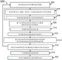
图1示出了根据实施例的用于识别脊柱中的神经轴间隙的超声成像系统的示意图;1 shows a schematic diagram of an ultrasound imaging system for identifying axonal gaps in the spine, according to an embodiment;
图2示出了根据实施例的图1的系统的照片;FIG. 2 shows a photograph of the system of FIG. 1 according to an embodiment;
图3示出了图1的系统的计算机的框图;Figure 3 shows a block diagram of a computer of the system of Figure 1;
图4示出了用于确定用于针插入的脊柱的最佳节段的方法的步骤;Figure 4 shows the steps of a method for determining the optimal segment of the spine for needle insertion;
图5示出了用于在使用图4的方法确定的脊柱的最佳节段处识别脊柱中的神经轴间隙的方法的步骤;FIG. 5 shows the steps of a method for identifying a nerve axis gap in the spine at the optimal segment of the spine determined using the method of FIG. 4;
图6示出了图3的计算机上的用户界面的图示;Figure 6 shows an illustration of a user interface on the computer of Figure 3;
图7示出了如通过图4的方法识别的在脊柱的最佳节段处获得的脊柱的旁正中矢状超声图像的用户界面的图示;7 shows an illustration of a user interface of a paramedian sagittal ultrasound image of the spine obtained at the optimal segment of the spine as identified by the method of FIG. 4;
图8示出了用于使用图4的方法识别脊柱的最佳节段的脊柱的旁正中矢状超声图像的示例;Figure 8 shows an example of a paramedian sagittal ultrasound image of the spine for identifying the optimal segment of the spine using the method of Figure 4;
图9示出了用于使用图5的方法识别神经轴间隙的脊柱的横向超声图像的用户界面的图示;以及FIG. 9 shows an illustration of a user interface for a transverse ultrasound image of the spine for identifying a nerve axis gap using the method of FIG. 5; and
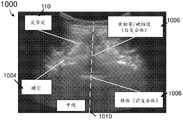
图10示出了用于使用图5的方法识别神经轴间隙的脊柱的横向超声图像的示例。FIG. 10 shows an example of a transverse ultrasound image of the spine used to identify the nerve axis gap using the method of FIG. 5 .
具体实施方式Detailed ways
示例性实施例涉及用于识别脊柱中的神经轴间隙的超声成像方法和系统。Exemplary embodiments relate to ultrasound imaging methods and systems for identifying axonal spaces in the spine.
图1示出了根据实施例的用于识别脊柱中的神经轴间隙的超声成像系统100的示意图。系统100包括计算机102和超声机器104。计算机与超声机器104通信,用于接收由超声机器104捕获的超声图像。计算机102与其操作系统及其安装的程序一起被配置为执行如下面的方法500和600中所讨论的操作。此外,系统100包括与计算机102通信的数据库106。数据库106是硬件组件,使得数据可以被传送到数据库106和从数据库106传送,并且在计算机102处被处理。在本实施例中,数据库106是外部硬盘驱动器。系统100包括与超声机器104通信的超声探头108。超声探头108用于生成超声波,该超声波传输通过患者的身体以用于识别患者的身体内的解剖结构,诸如脊柱。所传输的超声波由解剖结构反射并由超声探头108接收。这些接收到的超声波被转换为电信号,该电信号用于在超声机器104中形成超声视频或图像。原始视频和/或图像数据信号又从超声机器104传输到计算机102以进行进一步处理,例如根据下面将描述的方法400和500。1 shows a schematic diagram of an
图2示出了根据实施例的图1的系统100的照片。具体地,图2示出了紧凑的系统200,其可以与推车201集成以增加移动性。这在临床环境中尤其重要,因为整个系统200可以在推车201上四处移动以在各个位置处用于不同患者。此外,清楚的是,紧凑的超声成像系统200具有容易与现有超声机器集成的优点。例如,为了实施本方法,仅需要将计算机202连接到超声机器204,用于从超声机器204接收视频或图像数据以进行图像处理。FIG. 2 shows a photograph of the
计算机202至少包括被安装用于执行用于处理从超声机器204接收的超声图像的方法400和500的应用。计算机202被配置为经由视频捕获卡206从超声机器204接收输入。视频捕获卡206用于从超声机器204接收原始视频和/或图像信号,将原始数据转换为视频和/或图像,以及将视频和/或图像传输到计算机202以进行处理。计算机202连接到外部硬盘驱动器208,外部硬盘驱动器208可以用作本地数据库,用于自动存储这些超声视频和/或图像,和/或与支持向量机(SVM)的操作有关的其他数据,以用于处理这些接收到的视频和/或图像。
超声机器204连接到超声探头210,超声探头210用于发送和接收如上所述的超声波,以用于对患者中的解剖结构进行成像。此外,整个系统200可以放置在可伸缩的计算机支架212上,其允许调节计算机202和/或超声机器204的高度以满足用户的需要。The
在以下说明书中,超声成像系统100被描述为与超声引导的神经轴手术相关地使用。然而,应当理解,该系统100的使用可以扩展到其他解剖位置,包括但不限于区域阻滞、气道、身体成像或脊柱的其他解剖特征。如将在以下描述中变得清楚的,超声成像系统100为用户提供了一种自动确定安全且直接的插入位置和角度的方法,用于在实时超声引导下执行神经轴手术。In the following description, the
计算机102可以用作现有超声装置的附加物,诸如以如图2所示的方式。使用从现有超声机器104的视频输出端口收集的超声图像流,计算机102被配置为确定与手术相关的特征的位置并在用户界面上实时显示它们的位置。使用这些特征相对于超声探头108的位置,计算机102被配置为确定超声探头的位置和取向对于将针安全插入神经轴间隙以执行神经轴手术是否是最佳的。
通过集成计算机102及其用于从超声机器104获得超声扫描(例如,视频和/或图像)的附件,可以获得计算机实现的方法,其使用人工智能(AI)技术来识别脊柱的解剖特征以用于在神经轴手术中引导用户。这些在下面关于图4和图5进行描述。具体地,计算机102被配置为经由用户界面与用户交互,用于贯穿神经轴手术过程引导用户识别用于执行神经轴手术的最佳位置和/或倾斜角。这包括通过使用脊柱的旁正中矢状超声图像进行的脊柱节段识别,以及通过使用最佳脊柱节段处的横向超声图像进行的神经轴间隙识别,以用于识别用于执行神经轴手术的最佳位置和/或倾斜角。通过使用系统100,还可以在针插入过程期间从横向超声图像实时跟踪针。系统100还提供用于分析现有超声视频或图像的离线功能,这在微调下面的图4和图5的方法时是有用的。By integrating
因此,系统100及其相关联的计算机实现的方法提供以下优点。Accordingly, the
首先,系统100使得经验较少的用户(例如,经验较少的麻醉师或医生)能够进行神经轴手术,该用户借助于系统100及其相关联的计算机实现的方法能够以与有经验的用户类似的准确度和成功率执行神经轴手术。具体地,应注意,确定用于神经轴手术的针插入的位置是需要大量经验的困难任务。借助于系统100,脊柱的重要特征被自动标记,并且用户以逐步的方式被引导以首先定位用于针插入的最佳脊柱节段,然后实现用于执行神经轴手术的最佳水平位置和倾斜角。以这种方式,可以加速整个神经轴手术,同时保持神经轴手术的一致性和准确性。此外,提供系统性的逐步引导的手术还提高了手术的成功率,从而改善了患者体验并减少了由于多次失败的注射尝试而导致的并发症和不必要的不适的发生。此外,系统100还有助于涉及肥胖患者和/或具有脊柱病症的患者的困难情况下的神经轴手术。First, the
第二,系统100提供了对当前超声系统的紧凑添加,从而允许容易地集成到当前的临床工作流程中。系统100还被设计为即插即用的,因此仅需要将计算机102连接到超声机器104的视频输出端口并将超声探头108连接到超声机器104的探头输入端口。Second,
第三,通过其直观的用户界面和工作流程,系统100通过提供可以由经验较少的用户容易地识别的超声图像上的各种形态特征的指示来帮助加速对经验较少的用户的训练。以这种方式,还可以降低用于训练经验较少的用户的成本。Third, through its intuitive user interface and workflow, the
图3示出了图1的系统100的计算机102的框图。FIG. 3 shows a block diagram of the
如图3所示,计算机102是具有存储计算机程序模块的存储器的计算机系统,该计算机程序模块实现用于识别脊柱中的神经轴间隙的计算机实现的方法。计算机102包括处理器302、工作存储器304、输入模块306、输出模块308、用户界面310、程序存储装置312和数据存储装置314。处理器302可以被实现为一个或多个中央处理单元(CPU)芯片。程序存储装置312是非易失性存储设备,诸如硬盘驱动器,其存储诸如脊柱标志识别模块316的计算机程序模块。计算机程序模块被加载到工作存储器204中以供处理器202执行。输入模块306是允许计算机102接收数据(例如超声机器104中捕获的超声视频和/或图像的视频和/或图像数据等)的接口。输出模块308是允许输出由脊柱标志识别模块316处理的数据和分析结果的输出设备。输出模块308可以耦合到显示设备或打印机。用户界面310允许计算机102的用户输入选择和命令,并且可以被实现为图形用户界面。下面关于图6更详细地示出和描述了用于关于脊柱标志识别模块316来使用的用户界面。As shown in FIG. 3,
程序存储装置312存储脊柱标志识别模块316。脊柱标志识别模块316使处理器302执行关于图4和图5更详细描述的各种模拟和分析过程。在一些上下文中,程序存储装置312可以被称为计算机可读存储介质和/或非暂时性计算机可读介质。如图3中所描绘的,脊柱标志识别模块316被描绘为用于执行本发明的计算机实现的方法的单个模块。然而,应当理解,这里的边界设置仅是示例性的,并且替代实施例可以施加模块的功能的分解。例如,本文所讨论的脊柱标志识别模块316可以被分解为子模块,以作为多个计算机过程执行,并且可选地在多个计算机上执行。此外,替代实施例可以组合特定模块或子模块的多个实例。还应当理解,虽然本文描述了计算机程序模块的软件实现,但是这些可以替代地被实现为一个或多个硬件模块(诸如(一个或多个)现场可编程门阵列或(一个或多个)专用集成电路),其包括实现与软件中实现的功能等同的功能的电路。
数据存储装置314存储用于由脊柱标志识别模块316实现的各种模型数据。如图3所示,数据存储装置314具有用于骶骨识别模型320、棘突间间隙识别模型322、全景拼接模型324、神经轴间隙识别模型326和神经轴间隙深度计算模型328的存储装置。骶骨识别模型320存储与识别在旁正中矢状超声图像中获得的脊柱的部分的图像是否包括骶骨有关的数据。这包括用于区分骶骨的形态特征的历史数据,诸如轮廓线性度、尺寸、中心位置和/或面积。棘突间间隙识别模型322存储与用于识别脊柱中的棘突间间隙的特征有关的数据。例如,棘突间间隙识别模型322包括用于识别在模板匹配方法中使用的不同脊柱节段之间的椎板的数据。全景拼接模型324存储与确定另外的或随后的旁正中矢状超声图像是否适合于拼接到全景图像的前端有关的数据,例如,与计算另外的旁正中矢状超声图像和全景图像的前端之间的互相关强度有关的数据。神经轴间隙识别模型326存储与从横向超声图像提取脊柱的特征(例如,与神经轴间隙相关联的独特图案)和提取脊柱的中线特征有关的数据。神经轴间隙深度计算模型328存储与计算脊柱中的神经轴间隙的深度有关的数据。
尽管参考计算机描述了技术架构,但是应当理解,技术架构可以由彼此通信并协作以执行任务的两个或更多个计算机形成。例如但不作为限制,可以以允许应用的指令的并发和/或并行处理的方式划分应用。可替代地,由应用处理的数据可以以允许由两个或更多个计算机并发和/或并行处理数据集的不同部分的方式进行划分。在实施例中,技术架构可以采用虚拟化软件来提供不直接绑定到技术架构中的计算机数量的多个服务器的功能。在实施例中,可以通过在云计算环境中执行一个应用和/或多个应用来提供上面公开的功能。云计算可以包括使用动态可扩展计算资源经由网络连接提供计算服务。云计算环境可以由企业建立和/或可以根据需要从第三方提供商租用。Although the technical architecture is described with reference to computers, it should be understood that the technical architecture may be formed by two or more computers that communicate and cooperate with each other to perform tasks. For example and without limitation, applications may be partitioned in a manner that allows concurrent and/or parallel processing of the instructions of the applications. Alternatively, the data processed by the application may be partitioned in a manner that allows concurrent and/or parallel processing of different portions of the data set by two or more computers. In an embodiment, the technology infrastructure may employ virtualization software to provide the functionality of multiple servers that are not directly tied to the number of computers in the technology infrastructure. In an embodiment, the functionality disclosed above may be provided by executing an application and/or applications in a cloud computing environment. Cloud computing can include the use of dynamically scalable computing resources to provide computing services via network connections. Cloud computing environments can be established by enterprises and/or can be rented from third-party providers as needed.
与识别脊柱中的神经轴间隙有关的方法Methods related to identifying axonal gaps in the spine
图4和图5示出了与由图1的超声成像系统100执行的识别脊柱中的神经轴间隙有关的方法400、500。具体地,图4涉及用于识别用于执行神经轴手术的脊柱的最佳节段的方法400,而图5涉及识别用于在执行神经轴手术时插入针的神经轴间隙的方法500。应当理解,这些方法400、500中的每一个可以彼此独立地执行。例如,熟练的用户(例如,有经验的医生或麻醉师)可以在不使用图4的方法400的情况下通过手动触诊脊柱来识别用于执行神经轴手术的脊柱的最佳节段。FIGS. 4 and 5 illustrate
参考图4,在步骤402中,计算机102从超声机器104接收脊柱的部分的旁正中矢状超声图像。一旦在步骤402中接收到旁正中矢状超声图像,在本实施例中,处理旁正中矢状超声图像以减少图像中的噪声和/或任何不想要的伪影。使用可选步骤404和406来执行旁正中矢状超声图像的处理。在步骤404中,使用高斯差分(DoG)局部归一化滤波器来执行旁正中矢状超声图像的对比度增强,以去除斑点噪声并增强如旁正中矢状超声图像中所示的脊柱的该部分的解剖结构的对比度。在步骤406中,对比度增强的旁正中矢状超声图像经历进一步处理以消除候选轮廓点。这通过二元阈值处理来执行,并且可以随后进行形态变换,具体是扩张和侵蚀。Referring to FIG. 4 , in
在步骤408中,计算机102的脊柱标志识别模块316被布置为识别旁正中矢状超声图像的形态特征,以用于对脊柱的该部分进行分类,特别是用于确定旁正中矢状超声图像是否示出脊柱的骶骨。通常,在脊柱的纵向或旁正中矢状视图中,骶骨被示出为明亮的回声线,其与其他解剖脊柱结构相比具有更显著的长度。鉴于其形状特性,与骶骨相关联的形态特征可用于对骶骨进行分类。In
在步骤410中,计算机102的脊柱标志识别模块316被布置为基于步骤408的所识别的形态特征来确定旁正中矢状超声图像是否包括骶骨。所使用的形态特征的示例包括轮廓线性度、尺寸、中心位置和/或面积。在本实施例中,为了基于所识别的形态特征来确定旁正中矢状超声图像是否包括骶骨,使用机器学习算法。In
具体地,这些形态特征的历史数据是从在用于通过对来自视频流的图像进行采样和注释来构建骶骨识别模型320(例如,图像数据库)的先前研究期间收集的若干健康对象的视频记录的图像获得的。基于该历史数据,训练支持向量机(SVM)分类器以分类并确定在旁正中矢状超声图像中识别的轮廓是否属于骶骨的轮廓。SVM分类器是一种监督学习算法,其为训练集寻找具有最大裕度的决策边界(或分离超平面)。使用从这些健康对象收集的轮廓的形态特征来训练SVM分类器。表示骶骨的轮廓被标记为‘1’,并且表示其他结构的轮廓被标记为‘0’。在训练之后,经训练的SVM分类器被存储在计算机102或数据库106中以用于实时骶骨检测。Specifically, historical data for these morphological features was recorded from videos of several healthy subjects collected during previous studies used to construct a sacral identification model 320 (eg, an image database) by sampling and annotating images from video streams image obtained. Based on this historical data, a support vector machine (SVM) classifier is trained to classify and determine whether the contours identified in the paramedian sagittal ultrasound images belong to the contours of the sacrum. The SVM classifier is a supervised learning algorithm that finds the decision boundary (or separating hyperplane) with the largest margin for the training set. The SVM classifier was trained using the morphological features of the silhouettes collected from these healthy subjects. Contours representing the sacrum are marked as '1', and contours representing other structures are marked as '0'. After training, the trained SVM classifier is stored in
因此,在脊柱的超声扫描期间,与从超声机器104获得的旁正中矢状超声图像的每个可见解剖结构相关联的所提取的形态特征可以被馈送到经训练的SVM分类器中,以用于实时确定所研究的解剖结构是否包括骶骨。Thus, during an ultrasound scan of the spine, the extracted morphological features associated with each visible anatomical structure of the paramedian sagittal ultrasound image obtained from the
一旦确定旁正中矢状超声图像包括骶骨,就可以使用骶骨作为起始点来构建脊柱的全景图像。然后,全景图像能够用于识别脊柱的脊柱节段,并且因此识别用于执行神经轴手术的脊柱的最佳节段。可替代地,如果确定旁正中矢状超声图像不包括骶骨,则在步骤411中,计算机102被配置为提示用户重新定位超声探头108并重新扫描脊柱以提供用于步骤402的另一旁正中矢状超声图像。Once it is determined that the paramedian sagittal ultrasound image includes the sacrum, a panoramic image of the spine can be constructed using the sacrum as a starting point. The panoramic image can then be used to identify the spinal segment of the spine, and thus the optimal segment of the spine for performing nerve axis surgery. Alternatively, if it is determined that the paramedian sagittal ultrasound image does not include the sacrum, then in
如果在步骤410中确定旁正中矢状超声图像的脊柱的该部分包括骶骨,则在步骤412中,计算机102从超声机器104接收脊柱的另外的旁正中矢状超声图像。尽管在方法400中未示出,但是可以例如通过使用步骤404和406来过滤在步骤412中接收的另外的旁正中矢状超声图像,以获得良好的图像质量。在步骤414中,脊柱标志识别模块316被布置为确定在步骤412中接收的另外的旁正中矢状超声图像是否适合于拼接到该旁正中矢状超声图像以形成脊柱的全景图像的部分。为此,首先使用存储在例如棘突间间隙识别模型322中的数据经由模板匹配来识别脊柱的椎板的位置。基于形态特征和所提取的椎板的位置,可以识别棘突间间隙。棘突间间隙是不同脊柱节段的椎板之间的间隙。为了确定另外的旁正中矢状超声图像是否适合以良好的图像质量拼接到该旁正中矢状超声图像,基于椎板的模板匹配结果以及另外的旁正中矢状超声图像与先前处理的旁正中矢状超声图像(例如,在这种情况下,它将是骶骨的旁正中矢状超声图像)之间的互相关强度来选择另外的旁正中矢状超声图像。If it is determined in
如果在步骤414中确定另外的旁正中矢状超声图像适合于拼接到该旁正中矢状超声图像,则脊柱标志识别模块316被配置为在步骤416中将另外的旁正中矢状超声图像拼接到该旁正中矢状超声图像以形成脊柱的全景图像的部分。如果在步骤414中确定另外的旁正中矢状超声图像不适合于拼接到该旁正中矢状超声图像,则在步骤418中,计算机102被配置为提示用户重新定位超声探头108并重新扫描脊柱以获得用于步骤402的另外的旁正中矢状超声图像。换句话说,该过程从如图4所示的步骤402再次重新开始。If it is determined in
在步骤420中,脊柱标志识别模块316被配置为识别全景图像的部分的棘突间间隙的位置。这是通过使用相位相关方法计算该另外的旁正中矢状超声图像与该旁正中矢状超声图像的前沿之间的移位或运动、并且变换超声探头108的中心相对于该全景图像的该部分的坐标来实现的。In
一旦在步骤420中识别出棘突间间隙的位置,脊柱标志识别模块316被配置为使用棘突间间隙的位置相应地识别脊柱的当前脊柱节段。这可以通过对从骶骨到前导(leading)旁正中矢状超声图像的棘突间间隙的数量进行计数来实现。Once the location of the interspinous space is identified in
在这一点上,应当理解,尽管描述了用于将另外的旁正中矢状超声图像拼接到旁正中矢状超声图像以形成全景图像的部分的方法,但是为了形成全景图像,随后的旁正中矢状超声图像帧沿着扫描被逐步拼接。事实上,随着随后的旁正中矢状超声图像被逐步拼接以形成全景图像,可以对棘突间节段的数量进行计数,并且可以识别当前脊柱节段。At this point, it should be understood that although a method for stitching additional paramedian sagittal ultrasound images to a paramedian sagittal ultrasound image to form part of a panoramic image is described, subsequent paramedian sagittal ultrasound images are The ultrasound image frames are progressively stitched along the scan. In fact, as subsequent paramedian sagittal ultrasound images are progressively stitched to form a panoramic image, the number of interspinous segments can be counted and the current spinal segment can be identified.
在步骤424中,计算机102的脊柱标志识别模块316被配置为确定是否已经到达脊柱的最佳节段。这可以通过在步骤422中对脊柱节段进行计数来实现。在本实施例中,脊柱的最佳节段位于脊柱的L3-L4棘突间间隙的位置处。如果确定尚未到达脊柱的最佳节段,则计算机102的脊柱标志识别模块316被配置为返回到如图4所示的步骤412至422。一旦在步骤424中确定已经到达最佳节段,则计算机102的脊柱标志识别模块316被配置为在步骤426中通知用户已经到达脊柱的最佳节段并且向用户传输请求以获得最佳节段处的横向超声图像。In
图5示出了用于识别由图4的方法400确定的脊柱的最佳节段处的神经轴间隙的方法500的步骤。FIG. 5 illustrates the steps of a
一旦在方法400的步骤426处识别出最佳脊柱节段,计算机102的脊柱标志识别模块316就被配置为在步骤502中接收脊柱的部分的横向超声图像。为此,脊柱标志识别模块316被配置为提示用户沿着超声探头的纵轴将超声探头106旋转90度,以用于在脊柱的该部分的横向视图中生成横向超声图像。应当注意,在本实施例中,在最佳节段在脊柱的L3-L4棘突间间隙处的情况下,预期针对横向超声图像获得表征该棘突间间隙的独特的“飞行蝙蝠”类型的图案。Once the optimal spinal segment is identified at
类似于方法400的步骤404和406,一旦在步骤502中获得横向超声图像,在本实施例中,处理横向超声图像以减少图像中的噪声和/或任何不想要的伪影。可以使用可选步骤504和506来执行横向超声图像的处理。在步骤504中,使用高斯差分(DoG)局部归一化滤波器来执行横向超声图像的对比度增强,以去除斑点噪声并增强如横向超声图像中所示的脊柱的解剖结构的对比度。在步骤506中,对比度增强的横向超声图像经历进一步处理以消除候选轮廓点。这通过二元阈值处理来执行,并且可以随后进行形态变换,具体是扩张和侵蚀。步骤504和506有利地减少了横向超声图像中的噪声的影响,并且增强了对于识别神经轴间隙至关重要的解剖结构或特征。Similar to
在步骤508中,脊柱标志识别模块316被配置为基于与神经轴间隙相关联的独特图案从横向超声图像提取脊柱的该部分的特征。具体地,在由横向超声图像捕获的横向超声图像平面中,神经轴间隙通常由类似“飞行蝙蝠”的图案表征(参见例如图10)。基于该独特图案,脊柱标志识别模块316被配置为从横向超声图像中识别和提取一组特征。这也被称为模板匹配技术,其中基于来自有经验的超声医师的临床知识预先准备独特图案的一组模板,并且将其用于与横向超声图像相关联,以识别神经轴间隙的特征。在本实施例中,所提取的特征包括以下中的一个或多个:后复合体的深度、前复合体的深度、后复合体的归一化互相关强度、前复合体的归一化互相关强度、左关节突的位置、右关节突的位置、左关节突的归一化互相关值和右关节突的归一化互相关值。此外,可以提取用于模板匹配的两个附加特征以识别神经轴间隙,并且这些特征包括后复合体和前复合体的水平位置。所提取的这些附加特征有助于避免假阳性结果,假阳性结果可能在棘突图像产生其形状和深度类似于黄韧带/椎体的轮廓的情况下出现,从而导致在棘突间图像中获得类似的深度和归一化互相关值。In
在步骤510中,脊柱标志识别模块316被配置为识别横向超声图像中的脊柱的该部分的中线。中线是从横向超声图像的顶部跨越到横向超声图像的底部的线,并且可以通过使用与横向超声图像的预定义扫描窗口内的白色像素的存在相关联的成本函数来识别中线。扫描窗口与从中线的右侧和左侧跨越相等距离的区域相关联。通过计算一系列变量对的成本函数并选择提供最小成本函数的线来确定中线。变量对与(i)横向超声图像的第一行处的起始点和(ii)在横向超声图像的垂直轴与中线之间创建的角度相关联。每个变量对固定中线的位置。所使用的成本函数包括与像素的深度相关联的第一项和与中线相对于横向超声图像的中心的位置相关联的第二项。In
在步骤512中,脊柱标志识别模块316被配置为使用沿着中线的像素强度值来提取中线特征。具体地,沿着中线的中线特征可以用于区分骨骼的超声图像和神经轴间隙的超声图像。具体地,对于骨骼的图像,中线表现为暗的消声区域,因为棘突阻挡超声波更深地行进到体内。相比之下,对于神经轴间隙的图像,黄韧带、椎体和关节突的部分沿着中线是可见的,并且在横向超声图像中被示出为亮区域。在本实施例中,在步骤512中提取的中线特征包括横向超声图像的预定义窗口中的黑色像素的比率和横向超声图像中的后复合体下方的白色像素的比率。In
在步骤514中,脊柱标志识别模块316被配置为基于横向超声图像的脊柱的该部分的所提取的特征和所提取的中线特征的组合来识别神经轴间隙。具体地,将所提取的特征的组合馈送到SVM分类器中,并且将这些所提取的特征与存储在神经轴间隙识别模型326中的这些特征的历史数据进行比较,以识别神经轴间隙。用于使用方法500识别神经轴间隙的历史数据是从在先前研究期间收集的若干健康对象的视频和/或图像记录获得的。一旦获得这些历史数据,就可以通过对来自这些视频和/或图像流的图像进行采样和注释来构建神经轴间隙识别模型326的图像数据库。具体地,这些采样图像中的每一个被独立地标记,例如,“1”用于棘突间图像,并且“-1”用于棘突图像和不适合于针插入的其他图像。以这种方式,SVM分类器可以被训练并存储在计算机102的神经轴间隙识别模型326中,以用于实时神经轴间隙识别。随后,当在脊柱的扫描期间获得横向超声图像时,从横向超声图像所提取的特征的组合可以被馈送到SVM分类器中以用于识别神经轴间隙。In
在步骤516中,通过使用存储在神经轴间隙识别模型326中的SVM分类器,脊柱标志识别模块316被配置为确定神经轴间隙是否在横向超声图像中存在并且居中。如果在步骤516中确定神经轴间隙不在横向超声图像中存在并且居中,则脊柱标志识别模块316被配置为提示用户调节超声探头108的位置以获得另一横向超声图像,并且从步骤502到步骤516重复用于确定神经轴间隙是否在该横向超声图像中存在并且居中的过程。可替代地,如果确定神经轴间隙在横向超声图像中存在并且居中,则脊柱标志识别模块316被配置为在步骤518中计算神经轴间隙的深度,并且在步骤520中向用户传输请求以标记用于执行神经轴手术的地点的最终位置。In
如关于方法400和500所描述的,从脊柱的纵向超声图像和横向超声图像中识别和/或提取形态特征需要脊柱标志识别模块316能够通过使用存储在骶骨识别模型320、棘突间间隙识别模型322和神经轴间隙识别模型326中的历史数据来确定这些特征。As described with respect to
已经使用用于使用方法400、500执行神经轴手术的系统100进行了初步研究。在这些初步研究中,用户(例如,麻醉师)的任务是使用脊柱标志识别模块316来在插入之前确定最佳针插入点和角度以及确定神经轴间隙的估计深度。针插入由用户在脊柱标志识别模块316提供的引导下进行,该引导包括针位置、针插入的倾斜角和针插入的估计神经轴深度的信息。Preliminary studies have been conducted using the
脊柱标志识别模块316被配置为检测与神经轴手术相关的特征并在用户界面上实时显示它们的位置。利用这些特征相对于超声探头108的位置,程序可以推断探头的位置和取向对于朝向神经轴间隙的安全针插入是否是最佳的。然后将这些获得的结果反映在用户界面上,以首先指示用户沿着脊柱向上移动,直到超声探头108处于最佳脊柱节段,即L3-L4棘突间间隙,并且随后指示用户将超声探头在最佳脊柱节段旋转90度,以获得脊柱的横向视图,以用于识别神经轴间隙并获得用于针插入的最佳对准。在扫描每个患者之后,超声视频和/或图像被保存在计算机102或数据库106(例如,外部硬盘驱动器)中。此外,还保存了所生成的脊柱的纵向全景图像。这些超声视频和/或图像用于模型320、322、326的微调和/或训练。Spinal
图6示出了图1的计算机102上的用户界面600的图示。用户界面600涉及由脊柱标志识别模块316提供的不同功能,如关于上面的方法400、500所描述的。如图6所示的用户界面600的当前屏幕截图涉及在纵向旁正中视图中示出的界面(例如,用于获得旁正中矢状超声图像)。在脊柱的纵向旁正中视图和横向视图两者中的用户界面600的实际屏幕截图在下面关于图7和图9示出和描述。FIG. 6 shows an illustration of the
参考图6,标签602和604用于在脊柱的纵向旁正中视图和脊柱的横向视图之间切换。指示606用于向用户呈现信息或指令。功能键608用于使用户能够选择视频输入的源并将视频输入加载到模块316中。视频输入可以是存储在计算机102中的离线的现有超声视频文件或从超声机器104获得的实况超声扫描。本领域技术人员将理解,视频包括时间序列中的多个帧,其中多个帧中的每一个可以被提取为超声图像。框610用于在必要时向用户提供警报。框612示出了脊柱的部分的图示,其用于实时指示由超声探头108到达的精确棘突节段。在扫描过程期间将出现针形,以指示超声探头108到达的当前脊柱节段。窗口614用于示出超声视频和/或图像,其中由模块316检测到的解剖标志叠加在超声视频和/或图像上。窗口616用于呈现脊柱的拼接全景图像。随着旁正中矢状超声图像被拼接到全景图像的部分的前沿,窗口616实时示出全景图像。部分618用于实时指示超声探头到达的精确棘突节段。复选框620向用户提供查看预处理图像(例如,对比度增强的)的选项,其为超声图像的特征提供清晰度。Referring to Figure 6,
模块316还提供满足不同扫描深度的功能。这在框622中示出,框622允许用户选择两种不同的模式--正常模式和肥胖模式。在正常模式中(例如,对于常规尺寸的患者),使用78mm的扫描深度,而在肥胖模式中,使用92mm的扫描深度。通过具有两种不同的模式,模块316被配置为考虑针对肥胖患者获得的较差的超声图像质量并相应地调节图像分析。当选择任一模式时,将自动调节用于超声机器的扫描深度,并且这在框624中示出。例如,当选择正常模式时,框624中指示的扫描深度将是78mm。如果选择肥胖模式,则将示出92mm的扫描深度。
框626指示在脊柱的纵向旁正中视图和横向视图中执行扫描之后由程序估计的神经轴深度。框630提供在程序中捕获的视频的每秒帧数(FPS)的指示,其被设置为超声机器104的默认值。
框632为用户提供命名和编辑患者ID以用于标记扫描的手段,使得可以稍后识别所捕获的扫描或图像。在计算机102的根数据目录中自动创建每个患者ID的文件夹,用于存储这些扫描。最后,按钮634用于启动或停止程序进行的扫描过程。一旦通过按下按钮634启动扫描过程,则相同的按钮634将被改变为读为“停止扫描”。为了暂停扫描过程,可以再次点击按钮634。一旦扫描过程被暂停,按钮634将返回读为“开始扫描”。
如上所述,用户界面600突出显示与神经轴手术相关的脊柱的解剖结构。此外,它为手术期间的重要事件提供视觉和音频警告,包括超声探头108处于L3-L4棘突间间隙的时刻以及超声探头108的探头角度和取向对于执行针插入是最佳的时刻。As described above,
通过使用用户界面600,首先引导实施神经轴手术的用户(例如,麻醉师或医生)定位脊柱的骶骨。一旦脊柱的骶骨被定位,用户就被指示沿着脊柱向上或向下移动,直到超声探头108处于最佳脊柱节段,在该情况下为脊柱的L3-L4棘突间间隙。用户界面600被配置为当超声探头108已经到达最佳脊柱节段时警告用户。使用如上所述的方法400执行该过程。一旦超声探头108处于最佳脊柱节段,就指示用户调节超声探头108的角度并微调位置,直到实现最佳对准。当已经实现该最佳对准时,用户界面600将警告用户。此时,模块316计算目标神经轴间隙的深度。使用如上所述的方法500执行用于识别神经轴间隙以用于针的最佳对准的该后续过程。Using the
图7至图10示出了在临床试验期间获得的超声图像的示例。图7和图8示出了脊柱的旁正中矢状超声图像,而图9和图10示出了脊柱的横向超声图像。图7和图9是在临床试验期间拍摄的用户界面600的屏幕截图的示例,并且用于进一步示出在神经轴手术期间在用户界面600上看到的功能特征。7 to 10 show examples of ultrasound images obtained during clinical trials. Figures 7 and 8 show paramedian sagittal ultrasound images of the spine, while Figures 9 and 10 show transverse ultrasound images of the spine. 7 and 9 are examples of screen shots of the
图7是图示用于在如由图4的方法400识别的脊柱的最佳节段处获得的脊柱的该部分的旁正中矢状超声图像的用户界面600的屏幕截图700。FIG. 7 is a screen shot 700 illustrating a
参考图7,如用户界面600的框614所示,显示旁正中矢状超声图像。在用户界面600的框616中,显示脊柱的全景图像。如上文关于图4的方法400所描述的,从所识别的骶骨的旁正中矢状超声图像开始逐步地拼接所获得的旁正中矢状超声图像以形成全景图像。如图所示,在全景图像上指示棘突间节段。在用户界面600的框612中,脊柱的图示提供超声探头108的当前节段的指示704。类似的信息也在用户界面600的框606中指示,其中它读为“扫描:到达L3-L4”。停止”,以向用户提供已经到达最佳脊柱节段L3-L4并建议用户停止超声探头108的警告。另外,还在用户界面600的窗口618中提供指示708,以通知用户已经到达L3-L4脊柱节段。Referring to FIG. 7, as indicated by
图8示出了用于使用图4的方法识别脊柱的最佳节段的脊柱的部分的旁正中矢状超声图像的示例。标记脊柱的该部分的多个解剖特征以供参考。根据旁正中矢状超声图像800,可以识别脊柱的椎板802。例如,使用椎板的位置来识别棘突间间隙的位置。还在旁正中矢状超声图像800中识别脊柱的骶骨804。如上所述,骶骨形成全景图像的起始点,并且用作用于对脊柱节段进行计数的参考,以定位用于执行神经轴手术的脊柱的最佳节段。还在旁正中矢状超声图像800中识别黄韧带/硬脑膜(后复合体)806。FIG. 8 shows an example of a paramedian sagittal ultrasound image of a portion of the spine used to identify the optimal segment of the spine using the method of FIG. 4 . Various anatomical features of this portion of the spine are marked for reference. From the paramedian
图9示出了用于使用图5的方法500识别神经轴间隙的脊柱的部分的横向超声图像的用户界面600的图示。在最佳节段(即L3-L4棘突间间隙)处拍摄脊柱的横向超声图像。用户界面600在用户界面600的纵向旁正中视图和横向视图标签之间共享一些共同特征(例如,特征622-634)。FIG. 9 shows an illustration of a
参考图9,如用户界面600的框614所示,显示横向超声图像。此时,用户被引导微调超声探头108的位置和倾斜角,直到实现最佳对准。这可以使用如上所述的方法500通过在最佳脊柱节段处识别脊柱中的神经轴间隙来实现。一旦实现了最佳对准,用户界面600就通过在框902中示出对勾来提示用户,指示实现了超声探头108的最佳对准。此时,脊柱标志识别模块316计算并在框904处显示神经轴间隙的深度。在用户界面600上显示的横向超声图像中,还示出了中线和其他解剖特征的指示906,以帮助用户执行神经轴手术。然后,用户可以标记用于对患者执行神经轴手术的最终位置,并按照常规实践执行神经轴手术。Referring to FIG. 9, as indicated by
图10示出了用于使用图5的方法识别神经轴间隙的脊柱的部分的横向超声图像的示例。标记该横向超声图像中的多个解剖特征以供参考。参考脊柱的该部分的横向超声图像1000,可以识别关节突1002、横突1004、黄韧带/硬脑膜(后复合体)和椎体(前复合体)1008。这些识别的特征用于识别脊柱的该部分的神经轴间隙,如关于图5的方法500所描述的。另外,可以在横向超声图像中识别中线1010。中线1010的特征也用于识别神经轴间隙。FIG. 10 shows an example of a transverse ultrasound image of a portion of the spine used to identify the nerve axis gap using the method of FIG. 5 . Various anatomical features in the transverse ultrasound image are marked for reference. Referring to the
本发明的替代实施例包括:超声探头108是无线超声探头。此外,超声探头108可以包括夹紧系统,该夹紧系统被布置成将针固定到超声探头上以用于执行神经轴手术。夹紧系统可以包括基于弹簧加载机构的夹子,其中夹子被设计用于将针牢固地固定到其上。夹子还允许针容易地从探头脱离。夹子可以自由旋转并通过由球形接头机构实现的锁定系统锁定,使得针可以定位在用于手术的最佳位置和角度。具体地,一旦确定了最佳针插入位置和对准,硬膜外针或脊柱针就可以容易地卡在超声探头108上,并且可以通过超声探头108的中间实时地在平面内进行插入。在插入期间,系统100实时监测超声图像中针尖的位置并估计其距神经轴间隙的距离。同时,用户可以使用常规的阻力损失技术来确定针的插入深度。实时超声显示允许在计算机102上的用户界面中可视化阻力的损失,这有助于向用户指示何时应该停止针的推进。一旦针已经进入神经轴或脊柱间隙,针就可以容易地与超声探头108分离和脱离,并且可以以常规方式实施神经轴手术和药物施用。在一个实施例中,附接到超声探头108的夹紧系统可以是可以容易地夹在超声探头上的盖的形式。在其他实施例中,夹紧系统与超声探头108是一体的。Alternative embodiments of the present invention include that the
尽管仅详细描述了本发明的某些实施例,但是根据所附权利要求,许多变型是可能的。例如,关于一个实施例描述的特征可以结合到一个或多个其他实施例中,反之亦然。此外,尽管上面提供的示例性实施例特定于神经轴间隙的识别,但是应当理解,所描述的系统和方法也可以适用于脊柱的其他解剖特征,例如关节突、前复合体、后复合体和棘突间间隙。例如,如上面关于图4所描述,可以通过使用模板匹配方法识别不同脊柱节段之间的椎板来识别棘突间间隙。此外,本领域技术人员将理解,如关于图5描述的用于识别神经轴间隙的步骤502至514同样可以应用于脊柱的其他解剖特征。例如,一般地说,可以基于感兴趣的脊柱的解剖特征的已知图案来提取脊柱的该部分的特征,并且这些所提取的特征可以与步骤512的提取的中线特征组合使用,以便识别横向超声图像中的脊柱的解剖特征。这种一般化的方法可以应用于例如脊柱的关节突、前复合体和后复合体。因此,本领域技术人员将理解,系统300能够被修改以便适应对感兴趣的脊柱的解剖特征的识别。例如,诸如关节突识别模型和/或前复合体识别模型的其他模型可以包括在系统300中。While only certain embodiments of the invention have been described in detail, many modifications are possible in accordance with the appended claims. For example, features described in relation to one embodiment can be combined in one or more other embodiments, and vice versa. Additionally, while the exemplary embodiments provided above are specific to the identification of axonal gaps, it should be understood that the systems and methods described may also be applicable to other anatomical features of the spine, such as articular processes, anterior complexes, posterior complexes, and interspinous space. For example, as described above with respect to FIG. 4, interspinous spaces can be identified by using template matching methods to identify lamina between different spinal segments. Furthermore, those skilled in the art will understand that
Claims (39)
Translated fromChineseApplications Claiming Priority (3)
| Application Number | Priority Date | Filing Date | Title |
|---|---|---|---|
| SG10202000060V | 2020-01-03 | ||
| SG10202000060V | 2020-01-03 | ||
| PCT/SG2020/050786WO2021137761A1 (en) | 2020-01-03 | 2020-12-28 | Ultrasound imaging method and system for identifying an anatomical feature of a spine |
Publications (1)
| Publication Number | Publication Date |
|---|---|
| CN114930387Atrue CN114930387A (en) | 2022-08-19 |
Family
ID=76689736
Family Applications (1)
| Application Number | Title | Priority Date | Filing Date |
|---|---|---|---|
| CN202080091818.2APendingCN114930387A (en) | 2020-01-03 | 2020-12-28 | Ultrasound imaging method and system for identifying anatomical features of the spine |
Country Status (5)
| Country | Link |
|---|---|
| US (1) | US20230034589A1 (en) |
| EP (1) | EP4085419A4 (en) |
| CN (1) | CN114930387A (en) |
| AU (1) | AU2020418400A1 (en) |
| WO (1) | WO2021137761A1 (en) |
Cited By (1)
| Publication number | Priority date | Publication date | Assignee | Title |
|---|---|---|---|---|
| CN117679123A (en)* | 2023-12-22 | 2024-03-12 | 中国医科大学附属盛京医院 | A real-time ultrasound-guided automatic identification and positioning system for spinal anesthesia |
Families Citing this family (3)
| Publication number | Priority date | Publication date | Assignee | Title |
|---|---|---|---|---|
| US20220071595A1 (en)* | 2020-09-10 | 2022-03-10 | GE Precision Healthcare LLC | Method and system for adapting user interface elements based on real-time anatomical structure recognition in acquired ultrasound image views |
| CN116712102B (en)* | 2023-02-24 | 2025-09-26 | 华南理工大学 | A fully automatic spine ultrasound scanning method based on multi-source vision |
| CN118537519A (en)* | 2024-05-15 | 2024-08-23 | 中国医学科学院北京协和医院 | Automatic identification method for spinal dura mater structure |
Citations (1)
| Publication number | Priority date | Publication date | Assignee | Title |
|---|---|---|---|---|
| CN109561875A (en)* | 2016-08-18 | 2019-04-02 | 瑞文那医疗有限责任公司 | The system and method for detecting and its being imaged for ultrasonic vertebra shadow character |
Family Cites Families (8)
| Publication number | Priority date | Publication date | Assignee | Title |
|---|---|---|---|---|
| US20070242869A1 (en)* | 2006-04-12 | 2007-10-18 | Eastman Kodak Company | Processing and measuring the spine in radiographs |
| US8150110B2 (en)* | 2006-11-22 | 2012-04-03 | Carestream Health, Inc. | ROI-based rendering for diagnostic image consistency |
| US8858470B2 (en)* | 2007-01-29 | 2014-10-14 | Fraser Cummins Henderson | Method for treating a neurological disorder |
| US10140543B2 (en)* | 2015-04-03 | 2018-11-27 | Toshiba Medical Systems Corporation | Medical image processing apparatus, medical image processing method, and medical imaging device |
| CN109223032B (en)* | 2017-07-11 | 2022-02-08 | 中慧医学成像有限公司 | A method for detecting spine deformation by three-dimensional ultrasound imaging |
| US11166764B2 (en)* | 2017-07-27 | 2021-11-09 | Carlsmed, Inc. | Systems and methods for assisting and augmenting surgical procedures |
| EP3737295B1 (en)* | 2018-01-08 | 2025-08-27 | Rivanna Medical, Inc. | Three-dimensional imaging and modeling of ultrasound image data |
| US20190262609A1 (en)* | 2018-02-28 | 2019-08-29 | Boston Scientific Neuromodulation Corporation | Spinal cord stimulation based on patient-specific modeling |
- 2020
- 2020-12-28EPEP20910854.7Apatent/EP4085419A4/enactivePending
- 2020-12-28AUAU2020418400Apatent/AU2020418400A1/enactivePending
- 2020-12-28WOPCT/SG2020/050786patent/WO2021137761A1/ennot_activeCeased
- 2020-12-28USUS17/790,524patent/US20230034589A1/enactivePending
- 2020-12-28CNCN202080091818.2Apatent/CN114930387A/enactivePending
Patent Citations (2)
| Publication number | Priority date | Publication date | Assignee | Title |
|---|---|---|---|---|
| CN109561875A (en)* | 2016-08-18 | 2019-04-02 | 瑞文那医疗有限责任公司 | The system and method for detecting and its being imaged for ultrasonic vertebra shadow character |
| US20190192114A1 (en)* | 2016-08-18 | 2019-06-27 | Rivanna Medical Llc | System and Method for Ultrasound Spine Shadow Feature Detection and Imaging Thereof |
Non-Patent Citations (7)
| Title |
|---|
| (美)朗格等,王海昌等译: "《奈特心脏病学》", 30 June 2015, 人民军医出版社* |
| SHUANG YU等: "LUMBAR ULTRASOUND IMAGE FEATURE EXTRACTION AND CLASSIFICATION WITH SUPPORT VECTOR MACHINE", 2015 WORLD FEDERATION FOR ULTRASOUND IN MEDICINE & BIOLOGY, vol. 41, no. 10, 31 December 2015 (2015-12-31), pages 2677 - 2689, XP055839073, DOI: 10.1016/j.ultrasmedbio.2015.05.015* |
| SHUANG YU等: "REAL-TIME AUTOMATIC SPINAL LEVEL IDENTIFICATION WITH ULTRASOUND IMAGE PROCESSING", 2015 IEEE 12TH INTERNATIONAL SYMPOSIUM ON BIOMEDICAL IMAGING (ISBI), 23 July 2015 (2015-07-23), pages 243 - 246* |
| YUSONG LENG等: "Development of a Real-time Lumbar Ultrasound Image Processing System for Epidural Needle Entry Site Localization", 2016 38TH ANNUAL INTERNATIONAL CONFERENCE OF THE IEEE ENGINEERING IN MEDICINE AND BIOLOGY SOCIETY (EMBC), 18 October 2016 (2016-10-18), pages 4093 - 4096* |
| 刘道钦: "《兽医外科基本技术》", 31 March 1983, 河南科学技术出版社, pages: 87* |
| 杨高怡等: "《浅表淋巴疾病超声诊断》", 30 April 2019, 中华医学电子音像出版社, pages: 7* |
| 辛明志: "《新编简明临床超声诊断学》", 31 May 2008, 黑龙江科学技术出版社, pages: 140* |
Cited By (2)
| Publication number | Priority date | Publication date | Assignee | Title |
|---|---|---|---|---|
| CN117679123A (en)* | 2023-12-22 | 2024-03-12 | 中国医科大学附属盛京医院 | A real-time ultrasound-guided automatic identification and positioning system for spinal anesthesia |
| CN117679123B (en)* | 2023-12-22 | 2025-03-18 | 中国医科大学附属盛京医院 | An automatic identification and positioning system for spinal anesthesia under real-time ultrasound guidance |
Also Published As
| Publication number | Publication date |
|---|---|
| AU2020418400A1 (en) | 2022-07-21 |
| EP4085419A1 (en) | 2022-11-09 |
| US20230034589A1 (en) | 2023-02-02 |
| WO2021137761A1 (en) | 2021-07-08 |
| EP4085419A4 (en) | 2024-01-10 |
Similar Documents
| Publication | Publication Date | Title |
|---|---|---|
| CN114930387A (en) | Ultrasound imaging method and system for identifying anatomical features of the spine | |
| CN111214255B (en) | Medical ultrasonic image computer-aided method | |
| EP2883353B1 (en) | System and method of overlaying images of different modalities | |
| KR20210051141A (en) | Method, apparatus and computer program for providing augmented reality based medical information of patient | |
| JP7673750B2 (en) | Systems and methods for instantaneous picture quality feedback - Patents.com | |
| Tran et al. | Automatic detection of lumbar anatomy in ultrasound images of human subjects | |
| JP2018515197A (en) | Method and system for semantic segmentation in 2D / 2.5D image data by laparoscope and endoscope | |
| CN104248454B (en) | A kind of two-dimensional ultrasonic image and the coplanar determination methods of puncture needle | |
| US20200305837A1 (en) | System and method for guided ultrasound imaging | |
| US20120078102A1 (en) | 3-dimensional (3d) ultrasound system using image filtering and method for operating 3d ultrasound system | |
| CN112603373B (en) | Methods and systems for diagnosing tendon injury via ultrasound imaging | |
| KR102433473B1 (en) | Method, apparatus and computer program for providing augmented reality based medical information of patient | |
| US8644608B2 (en) | Bone imagery segmentation method and apparatus | |
| Daoud et al. | A hybrid camera-and ultrasound-based approach for needle localization and tracking using a 3D motorized curvilinear ultrasound probe | |
| KR101988531B1 (en) | Navigation system for liver disease using augmented reality technology and method for organ image display | |
| Leng et al. | Development of a real-time lumbar ultrasound image processing system for epidural needle entry site localization | |
| JP5005139B2 (en) | Region extraction method, region extraction apparatus, and X-ray CT apparatus | |
| Yu et al. | Ultrasound guided automatic localization of needle insertion site for epidural anesthesia | |
| KR20130110544A (en) | The method and apparatus for indicating a medical equipment on an ultrasound image | |
| Chmielewski et al. | Image registration | |
| KR101144867B1 (en) | 3d ultrasound system for scanning inside human body object and method for operating 3d ultrasound system | |
| Ikhsan et al. | Gabor-based automatic spinal level identification in ultrasound | |
| JP2020142018A (en) | Dynamic image analysis system and dynamic image processing device | |
| JP7394959B2 (en) | Medical image processing device, medical image processing method and program, medical image display system | |
| TWI761954B (en) | Tissue imaging method |
Legal Events
| Date | Code | Title | Description |
|---|---|---|---|
| PB01 | Publication | ||
| PB01 | Publication | ||
| SE01 | Entry into force of request for substantive examination | ||
| SE01 | Entry into force of request for substantive examination |