CN114930275A - Information input/output system - Google Patents
Information input/output systemDownload PDFInfo
- Publication number
- CN114930275A CN114930275ACN202180008325.2ACN202180008325ACN114930275ACN 114930275 ACN114930275 ACN 114930275ACN 202180008325 ACN202180008325 ACN 202180008325ACN 114930275 ACN114930275 ACN 114930275A
- Authority
- CN
- China
- Prior art keywords
- information
- sensor
- information processing
- electrode
- signal
- Prior art date
- Legal status (The legal status is an assumption and is not a legal conclusion. Google has not performed a legal analysis and makes no representation as to the accuracy of the status listed.)
- Pending
Links
Images


Classifications
- G—PHYSICS
- G06—COMPUTING OR CALCULATING; COUNTING
- G06F—ELECTRIC DIGITAL DATA PROCESSING
- G06F3/00—Input arrangements for transferring data to be processed into a form capable of being handled by the computer; Output arrangements for transferring data from processing unit to output unit, e.g. interface arrangements
- G06F3/01—Input arrangements or combined input and output arrangements for interaction between user and computer
- G06F3/03—Arrangements for converting the position or the displacement of a member into a coded form
- G06F3/041—Digitisers, e.g. for touch screens or touch pads, characterised by the transducing means
- G06F3/0416—Control or interface arrangements specially adapted for digitisers
- G06F3/04162—Control or interface arrangements specially adapted for digitisers for exchanging data with external devices, e.g. smart pens, via the digitiser sensing hardware
- G—PHYSICS
- G06—COMPUTING OR CALCULATING; COUNTING
- G06F—ELECTRIC DIGITAL DATA PROCESSING
- G06F3/00—Input arrangements for transferring data to be processed into a form capable of being handled by the computer; Output arrangements for transferring data from processing unit to output unit, e.g. interface arrangements
- G06F3/01—Input arrangements or combined input and output arrangements for interaction between user and computer
- G06F3/03—Arrangements for converting the position or the displacement of a member into a coded form
- G06F3/033—Pointing devices displaced or positioned by the user, e.g. mice, trackballs, pens or joysticks; Accessories therefor
- G06F3/0354—Pointing devices displaced or positioned by the user, e.g. mice, trackballs, pens or joysticks; Accessories therefor with detection of 2D relative movements between the device, or an operating part thereof, and a plane or surface, e.g. 2D mice, trackballs, pens or pucks
- G06F3/03545—Pens or stylus
- G—PHYSICS
- G06—COMPUTING OR CALCULATING; COUNTING
- G06F—ELECTRIC DIGITAL DATA PROCESSING
- G06F3/00—Input arrangements for transferring data to be processed into a form capable of being handled by the computer; Output arrangements for transferring data from processing unit to output unit, e.g. interface arrangements
- G06F3/01—Input arrangements or combined input and output arrangements for interaction between user and computer
- G06F3/03—Arrangements for converting the position or the displacement of a member into a coded form
- G06F3/033—Pointing devices displaced or positioned by the user, e.g. mice, trackballs, pens or joysticks; Accessories therefor
- G06F3/038—Control and interface arrangements therefor, e.g. drivers or device-embedded control circuitry
- G06F3/0383—Signal control means within the pointing device
- G—PHYSICS
- G06—COMPUTING OR CALCULATING; COUNTING
- G06F—ELECTRIC DIGITAL DATA PROCESSING
- G06F3/00—Input arrangements for transferring data to be processed into a form capable of being handled by the computer; Output arrangements for transferring data from processing unit to output unit, e.g. interface arrangements
- G06F3/01—Input arrangements or combined input and output arrangements for interaction between user and computer
- G06F3/03—Arrangements for converting the position or the displacement of a member into a coded form
- G06F3/041—Digitisers, e.g. for touch screens or touch pads, characterised by the transducing means
- G06F3/0416—Control or interface arrangements specially adapted for digitisers
- G—PHYSICS
- G06—COMPUTING OR CALCULATING; COUNTING
- G06F—ELECTRIC DIGITAL DATA PROCESSING
- G06F3/00—Input arrangements for transferring data to be processed into a form capable of being handled by the computer; Output arrangements for transferring data from processing unit to output unit, e.g. interface arrangements
- G06F3/01—Input arrangements or combined input and output arrangements for interaction between user and computer
- G06F3/03—Arrangements for converting the position or the displacement of a member into a coded form
- G06F3/041—Digitisers, e.g. for touch screens or touch pads, characterised by the transducing means
- G06F3/044—Digitisers, e.g. for touch screens or touch pads, characterised by the transducing means by capacitive means
- G06F3/0441—Digitisers, e.g. for touch screens or touch pads, characterised by the transducing means by capacitive means using active external devices, e.g. active pens, for receiving changes in electrical potential transmitted by the digitiser, e.g. tablet driving signals
- G—PHYSICS
- G06—COMPUTING OR CALCULATING; COUNTING
- G06F—ELECTRIC DIGITAL DATA PROCESSING
- G06F3/00—Input arrangements for transferring data to be processed into a form capable of being handled by the computer; Output arrangements for transferring data from processing unit to output unit, e.g. interface arrangements
- G06F3/01—Input arrangements or combined input and output arrangements for interaction between user and computer
- G06F3/03—Arrangements for converting the position or the displacement of a member into a coded form
- G06F3/041—Digitisers, e.g. for touch screens or touch pads, characterised by the transducing means
- G06F3/044—Digitisers, e.g. for touch screens or touch pads, characterised by the transducing means by capacitive means
- G06F3/0442—Digitisers, e.g. for touch screens or touch pads, characterised by the transducing means by capacitive means using active external devices, e.g. active pens, for transmitting changes in electrical potential to be received by the digitiser
- G—PHYSICS
- G06—COMPUTING OR CALCULATING; COUNTING
- G06F—ELECTRIC DIGITAL DATA PROCESSING
- G06F3/00—Input arrangements for transferring data to be processed into a form capable of being handled by the computer; Output arrangements for transferring data from processing unit to output unit, e.g. interface arrangements
- G06F3/01—Input arrangements or combined input and output arrangements for interaction between user and computer
- G06F3/03—Arrangements for converting the position or the displacement of a member into a coded form
- G06F3/041—Digitisers, e.g. for touch screens or touch pads, characterised by the transducing means
- G06F3/044—Digitisers, e.g. for touch screens or touch pads, characterised by the transducing means by capacitive means
- G06F3/0446—Digitisers, e.g. for touch screens or touch pads, characterised by the transducing means by capacitive means using a grid-like structure of electrodes in at least two directions, e.g. using row and column electrodes
Landscapes
- Engineering & Computer Science (AREA)
- General Engineering & Computer Science (AREA)
- Theoretical Computer Science (AREA)
- Human Computer Interaction (AREA)
- Physics & Mathematics (AREA)
- General Physics & Mathematics (AREA)
- Position Input By Displaying (AREA)
- User Interface Of Digital Computer (AREA)
Abstract
Translated fromChinese
Description
Translated fromChinese技术领域technical field
本发明涉及由例如电子笔等的指示操作装置和进行与该指示操作装置的指示输入对应的处理的信息处理装置构成的信息输入输出系统。The present invention relates to an information input/output system including an instruction operation device such as an electronic pen, and an information processing device that performs processing corresponding to an instruction input from the instruction operation device.
背景技术Background technique
近年来,已经使用了如下的系统,能够通过电子笔等指示操作装置和由搭载检测由电子笔指示的位置的位置检测功能等、检测来自指示操作装置的指示操作的功能的计算机等构成的信息处理装置交互(交互式)地进行各种处理。In recent years, systems have been used that can instruct an operation device with an electronic pen or the like, and a computer or the like equipped with a function to detect an instruction operation from the instruction operation device, such as a position detection function that detects the position pointed by the electronic pen, or the like The processing means interactively (interactively) performs various processes.
例如在专利文献1(日本特开2003-323455号公报)中,公开了一种关联信息提供装置,其根据针对影像中的被摄体的指示定时,提供对信息提供者而言在该定时相应的关联信息。在该专利文献1的可交互的系统中,根据指示操作装置中的指示操作,信息处理装置取得处理中的信息的关联信息,能够用于该时间点的显示、处理,很便利。For example, Patent Document 1 (Japanese Laid-Open Patent Publication No. 2003-323455 ) discloses a related information providing device that, based on an instruction timing with respect to a subject in a video, provides information corresponding to the timing for the information provider associated information. In the interactive system of
现有技术文献prior art literature
专利文献Patent Literature
专利文献1:日本特开2003-323455号公报Patent Document 1: Japanese Patent Laid-Open No. 2003-323455
发明内容SUMMARY OF THE INVENTION
发明所要解决的课题The problem to be solved by the invention
然而,如果信息处理装置不仅能够将与指示操作装置中的指示操作对应的信息用于该时间点的显示、处理,还能够传送到其他装置而显示,或在其他装置中利用,则很便利。However, it would be convenient if the information processing device could not only display and process the information corresponding to the instruction operation in the instruction operation device at that point in time, but also transmit it to another device to display or use it in another device.
但是,以往,如专利文献1那样,一般设想与指示操作装置中的指示操作对应的信息在信息处理装置侧用于处理。因此,在考虑了这样的信息的传送等的情况下,需要在将根据指示操作装置中的指示操作而取得的信息在信息处理装置中暂时存储后,存储在USB(Universal Sirial Bus,通用串行总线)存储器、卡式存储器,或者取出而用于传送等操作,很麻烦。However, conventionally, as in
本发明鉴于以上的问题点,其目的在于提供一种信息输入输出系统,其能够容易地取得与指示操作装置中的指示操作对应的信息,并向其他装置传送。In view of the above problems, the present invention has an object to provide an information input/output system that can easily acquire information corresponding to an instruction operation in an instruction operation device and transmit it to another device.
用于解决课题的技术方案Technical solutions for solving problems
为了解决上述课题,提供一种信息输入输出系统,由指示操作装置和信息处理装置构成,所述信息处理装置具备传感器,其中,In order to solve the above-mentioned problems, there is provided an information input/output system including an instruction operation device and an information processing device including a sensor, wherein:
所述指示操作装置具备:The indicating operation device includes:
第一电极及第二电极;a first electrode and a second electrode;
信号产生部,产生向所述信息处理装置发送的信号;a signal generating unit that generates a signal to be sent to the information processing device;
第一发送部,用于将来自所述信号产生电路的信号通过第一电极或第二电极发送到所述信息处理装置的所述传感器;a first sending unit for sending a signal from the signal generating circuit to the sensor of the information processing device through a first electrode or a second electrode;
接收部,通过所述第一电极或所述第二电极接收来自所述信息处理装置的信息;a receiving unit for receiving information from the information processing device through the first electrode or the second electrode;
信息存储部,存储由所述接收部接收到的信息;及an information storage unit that stores information received by the receiving unit; and
送出用部,用于将存储于所述信息存储部的信息送出到外部,a sending unit for sending the information stored in the information storage unit to the outside,
所述信息处理装置具备:The information processing device includes:
处理部,对通过所述传感器从所述指示操作装置接收到的信号进行处理;a processing unit for processing the signal received from the instruction operation device through the sensor;
取得部,取得与所述处理部的处理结果对应的信息;及an obtaining unit that obtains information corresponding to the processing result of the processing unit; and
第二发送部,将由所述取得部取得的所述信息通过所述传感器发送到所述指示操作装置。A second transmission unit transmits the information acquired by the acquisition unit to the instruction operation device via the sensor.
在上述结构的信息输入输出系统中,指示操作装置将来自信号产生电路的信号通过第一电极或第二电极发送到信息处理装置的传感器。信息处理装置在通过传感器接收到来自指示操作装置的信号时,对该接收到的信号进行处理,并根据该处理结果将取得的信息通过传感器发送到指示操作装置。指示操作装置通过第一电极或第二电极接收来自信息处理装置的信息,并将该接收到的信息存储到存储部中。然后,指示操作装置能够将存储于存储部的信息通过送出用部送出到外部。In the above-structured information input/output system, the operating device is instructed to transmit the signal from the signal generating circuit to the sensor of the information processing device through the first electrode or the second electrode. When the information processing device receives a signal from the instruction operation device through the sensor, it processes the received signal, and transmits the acquired information to the instruction operation device through the sensor according to the processing result. The instructing operation device receives information from the information processing device through the first electrode or the second electrode, and stores the received information in the storage unit. Then, the instruction operation device can send the information stored in the storage unit to the outside through the sending unit.
因此,根据上述结构的信息输入输出系统,当从指示操作装置通过传感器向信息处理装置发送信号时,从信息处理装置通过传感器向指示操作装置发送与接收到的信号的处理结果对应的信号,因此指示操作装置能够将来自该信息处理装置的信息存储到存储部中,并适当地通过送出用部传送到其他装置等。即,指示操作装置在通过传感器发送信号时,从信息处理装置通过传感器发送来规定的信息,因此能够存储保持该信息而传送到其他装置,通过简单的操作从信息处理装置取得信息并传送。Therefore, according to the information input/output system of the above configuration, when a signal is transmitted from the instruction operation device to the information processing device through the sensor, a signal corresponding to the processing result of the received signal is transmitted from the information processing device through the sensor to the instruction operation device. The instruction operation device can store the information from the information processing device in the storage unit, and transmit it to another device or the like through the sending unit as appropriate. That is, since the instructing operation device transmits predetermined information through the sensor from the information processing device when the signal is transmitted by the sensor, the information can be stored and retained and transmitted to another device, and the information can be acquired and transmitted from the information processing device by a simple operation.
附图说明Description of drawings
图1是用于说明本发明的信息处理系统的第一实施方式的结构例的概要的图。FIG. 1 is a diagram for explaining an outline of a configuration example of a first embodiment of an information processing system of the present invention.
图2是用于说明构成本发明的信息处理系统的第一实施方式的信息处理装置的结构例的图。2 is a diagram for explaining a configuration example of an information processing apparatus constituting the first embodiment of the information processing system of the present invention.
图3是用于说明作为构成本发明的信息处理系统的第一实施方式的指示操作装置的例子的电子笔的结构例的图。3 is a diagram for explaining a configuration example of an electronic pen as an example of a pointing operation device constituting the first embodiment of the information processing system of the present invention.
图4是用于说明作为构成本发明的信息处理系统的第一实施方式的指示操作装置的例子的电子笔的动作的图。4 is a diagram for explaining the operation of the electronic pen as an example of the pointing operation device constituting the first embodiment of the information processing system of the present invention.
图5是用于说明本发明的信息处理系统的第一实施方式的处理动作例的图。5 is a diagram for explaining a processing operation example of the first embodiment of the information processing system of the present invention.
图6是表示用于说明作为构成本发明的信息处理系统的第一实施方式的指示操作装置的例子的电子笔的动作的流程的流程图的一部分的图。6 is a diagram showing a part of a flowchart for explaining the flow of the operation of the electronic pen as an example of the instruction operation device constituting the first embodiment of the information processing system of the present invention.
图7是表示用于说明作为构成本发明的信息处理系统的第一实施方式的指示操作装置的例子的电子笔的动作的流程的流程图的一部分的图。7 is a diagram showing a part of a flowchart for explaining the flow of the operation of the electronic pen as an example of the instruction operation device constituting the first embodiment of the information processing system of the present invention.
图8是表示用于说明作为构成本发明的信息处理系统的第一实施方式的指示操作装置的例子的电子笔的动作的流程的流程图的一部分的图。8 is a diagram showing a part of a flowchart for explaining the flow of the operation of the electronic pen as an example of the instruction operation device constituting the first embodiment of the information processing system of the present invention.
图9是表示用于说明构成本发明的信息处理系统的第一实施方式的信息处理装置的动作的流程的流程图的一部分的图。9 is a diagram showing a part of a flowchart for explaining the flow of the operation of the information processing apparatus constituting the first embodiment of the information processing system of the present invention.
图10是表示用于说明构成本发明的信息处理系统的第一实施方式的信息处理装置的动作的流程的流程图的一部分的图。10 is a diagram showing a part of a flowchart for explaining the flow of the operation of the information processing apparatus constituting the first embodiment of the information processing system of the present invention.
图11是用于说明本发明的信息处理系统的第二实施方式的结构例的图。11 is a diagram for explaining a configuration example of a second embodiment of the information processing system of the present invention.
图12是用于说明作为构成本发明的信息处理系统的第二实施方式的指示操作装置的例子的电子笔的结构例的图。12 is a diagram for explaining a configuration example of an electronic pen as an example of a pointing operation device constituting a second embodiment of the information processing system of the present invention.
图13是用于说明构成本发明的信息处理系统的第二实施方式的信息处理装置的传感器的结构例的图。FIG. 13 is a diagram for explaining a configuration example of a sensor constituting an information processing apparatus according to a second embodiment of the information processing system of the present invention.
图14是用于说明构成本发明的信息处理系统的第二实施方式的信息处理装置的结构例的图。14 is a diagram for explaining a configuration example of an information processing apparatus constituting a second embodiment of the information processing system of the present invention.
图15是用于说明构成本发明的信息处理系统的第二实施方式的信息处理装置的传感器的其他结构例的图。15 is a diagram for explaining another configuration example of a sensor constituting the information processing apparatus according to the second embodiment of the information processing system of the present invention.
图16是用于说明构成本发明的信息处理系统的实施方式的指示操作装置的其他结构例的图。16 is a diagram for explaining another configuration example of the instruction operation device constituting the embodiment of the information processing system of the present invention.
具体实施方式Detailed ways
以下,参照附图对本发明的信息输入输出系统的实施方式进行说明。Hereinafter, embodiments of the information input/output system of the present invention will be described with reference to the drawings.
[第一实施方式][First Embodiment]
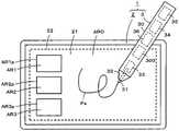
图1是用于说明本发明的信息输入输出系统的第一实施方式的概要的图。如图1所示,第一实施方式的信息输入输出系统1由例如由个人计算机构成的信息处理装置2和作为指示操作装置的例子的电子笔3构成。而且,在本实施方式中,信息处理装置2具备图2所示的结构,另外,电子笔3具有图3所示的电子电路结构。FIG. 1 is a diagram for explaining the outline of the first embodiment of the information input/output system of the present invention. As shown in FIG. 1 , the information input/
[信息处理装置2的结构例][Configuration example of information processing device 2]
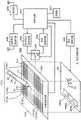
即,如图1及图2所示,本实施方式的信息处理装置2具备静电电容方式的位置检测传感器21作为传感器的例子并且具备以与该位置检测传感器21重叠的方式重叠设置的显示设备22。显示设备22例如由液晶显示器或有机EL(Electro luminescence,电致发光)等平板型的显示设备构成。That is, as shown in FIGS. 1 and 2 , the
如图2所示,位置检测传感器21重叠配置于显示设备22的显示画面的表面侧。在该情况下,位置检测传感器21的位置检测区域配置成与显示设备22的显示画面的显示区域大致一致。此外,在图1中,显示设备21的显示画面的显示区域由虚线表示。As shown in FIG. 2 , the
在该例子中,位置检测传感器21使用与显示设备22的显示画面对应的矩形的片状的透明基板211,在该透明基板211的表面侧,在该例中,由在Y轴方向上相互隔开规定间隔并列地配置有在横向(X轴方向)上延伸的多个第一导体212Y1、212Y2、…、212Ym(m为1以上的整数)的第一导体组212、和在X轴方向上相互隔开规定间隔并列地配置有在与横向正交的纵向(Y轴方向)上延伸的多个第二导体213X1、213X2、…、213Xn(n为1以上的整数)的第二导体组213构成。此外,在以下的说明中,当不需要区分多个第一导体及多个第二导体的每一个时,称为第一导体212Y及第二导体213X。In this example, a rectangular sheet-shaped
位置检测传感器21及显示设备22与信息处理装置的处理电路200连接。处理电路200是相对于控制信息处理装置2的整体的控制电路201连接导体选择电路202、切换开关电路203、位置检测电路204、发送信息处理电路205、显示控制电路206、存储部207、近距离无线通信部208及通信部209而构成的。The
位置检测传感器21的第一导体组212及第二导体组213的多个导体分别与导体选择电路202连接,导体选择电路202根据来自控制电路201的控制信号,选择这些第一导体组212及第二导体组213的多个导体中的1个或多个导体。The conductors of the
导体选择电路202与切换开关电路203连接。切换开关电路203根据来自控制电路201的切换控制信号,在接收到来自位置检测传感器21的信号时(接收模式)与从位置检测传感器21发送信息时(发送模式)之间进行切换。The
即,如后所述,切换开关电路203在利用位置检测传感器21接收到来自电子笔3的信号的接收模式时,根据来自控制电路201的切换控制信号,切换到端子R侧,将由导体选择电路202选择的导体切换为与位置检测电路204的输入端连接。另外,在从位置检测传感器21发送信息的发送模式时,根据来自控制电路201的切换控制信号,切换到端子T侧,将由导体选择电路202选择的导体切换为与发送信息处理电路205的输出端连接。在本实施方式中,如后所述,构成为,信息处理装置2的控制电路201与电子笔3取得定时的同步,以分时方式执行发送模式和接收模式。That is, as will be described later, when the
位置检测电路204检测来自由导体选择电路202选择的导体的接收信号的信号电平,根据该检测结果,检测由电子笔3指示的位置。然后,位置检测电路204将该检测到的位置的信息供给到控制电路201。控制电路201根据接收到的电子笔的指示位置的信息,执行后述那样的处理。The
在本实施方式中,位置检测电路204根据来自由导体选择电路202选择的导体的接收信号,检测从电子笔3发送来的笔压信息、笔识别信息(以下称为笔ID),还进行将该检测到的笔压信息、笔ID供给到控制电路201的处理。而且,位置检测电路204还进行根据来自由导体选择电路202选择的导体的接收信号来检测电子笔3的倾斜的处理,还进行将检测到的倾斜的信息供给到控制电路201的处理。In the present embodiment, the
发送信息处理电路205将来自控制电路201的发送信息转换(调制)为适于通过位置检测传感器21向电子笔3发送的信号,将该转换(调制)后的信号通过切换开关电路203供给到由导体选择电路202选择的导体,向电子笔3送出。The transmission
显示控制电路206与显示设备22连接,接收来自控制电路201的显示图像信息,以将与该显示图像信息对应的显示图像显示于显示设备22的显示画面的方式进行控制。The
存储部207根据控制电路201的控制,进行信息的存储及读出。在本实施方式中,在位置检测传感器21的与显示设备22的显示区域对应的检测区域,预先设定有多个局部检测区域。即,在图1的例子中,在位置检测传感器21的检测区域内设定有矩形的3个局部检测区域AR1、AR2、AR3。而且,在本实施方式中,这些3个局部检测区域AR1、AR2、AR3以外的区域AR0为电子笔2的书写输入检测区域。如图1及图2所示,在显示设备22的显示画面上显示用于使使用者视觉上认识局部检测区域AR1、AR2、AR3的区域框图像AR1p、AR2p、AR3p。The
在本实施方式中,控制电路201构成为能够执行根据电子笔3的指示位置是位置检测传感器21的检测区域内的哪个区域内的位置而不同的、与各个区域对应地预先设定的功能处理。而且,存储部207具备与书写输入检测区域AR0及局部检测区域AR1、AR2、AR3分别建立对应的存储区域。In the present embodiment, the
控制电路201进行与电子笔3的指示位置是位置检测传感器21的检测区域内的哪个区域内的位置对应的处理控制,并且进行针对存储部207的与区域对应的存储区域的写入或者读出的处理控制。在控制电路201中安装有该处理控制程序。The
关于与位置检测传感器21的检测区域内的书写输入检测区域AR0及局部检测区域AR1、AR2、AR3对应地设定的功能处理的例子,将在后面叙述。此外,局部检测区域并不限定于该例那样的3个局部检测区域AR1、AR2、AR3,也可以是1个、2个,另外,也可以是4个以上。而且,各部分区域的大小及形状也是任意的,例如能够通过电子笔3在位置检测传感器21上,指定其位置、大小及形状。而且,对各局部检测区域设定的功能也可以通过例如信息处理装置2将可设定的功能的菜单的一览显示在显示设备22的显示画面上,并通过电子笔3从一览进行选择指示来进行设定。An example of functional processing set in correspondence with the writing input detection area AR0 and the partial detection areas AR1 , AR2 , and AR3 in the detection area of the
如后所述,近距离无线通信部208用于与设置于电子笔3的近距离无线通信部之间进行无线通信,在本实施方式中,设为蓝牙(注册商标)标准无线通信部的结构。控制电路201构成为能够进行如下处理:将通过该近距离无线通信部208取得的信息存储于存储部207,或者将与该取得的信息对应的图像供给到显示控制电路206,显示在显示设备22的显示画面中。As will be described later, the short-range
在本实施方式中,通信部209用于通过通信线路与因特网连接,或者与特定的对方进行通信(邮件等)。控制电路201构成为能够进行如下处理:将通过该通信部209取得的信息存储在存储部207中,或者将与该取得的信息对应的图像供给到显示控制电路206,显示在显示设备22的显示画面中。In the present embodiment, the
[电子笔3的结构例][Configuration example of electronic pen 3]
本实施方式的电子笔3为与信息处理装置2的静电电容方式的位置检测传感器21交互的静电电容方式的结构。如图1所示,该例的电子笔3具备笔型的筒状的框体30,将该框体30的轴心方向的一端侧作为笔尖侧,在该笔尖侧,设置有构成第一电极的芯体(中心电极)31、构成第二电极的周边电极32。周边电极32在与芯体31绝缘的状态下,以包围该芯体31的周围的方式配置,如图所示,具有越靠近芯体31的前端侧则越尖细的锥形状。The
而且,在框体30的中空部内,如在图1中分别由虚线所示,设置有检测施加于芯体31的前端的压力(笔压)的笔压检测部33、信息存储部34、近距离无线通信部35、笔ID存储部36,并且设置有省略图示的配置在印刷基板上的电子笔电路300。笔压检测部33例如是检测施加的笔压作为静电电容的变化的、公知的可变电容器的结构。Further, in the hollow portion of the
图3是用于包含该电子笔电路300与笔压检测部33、信息存储部34、近距离无线通信部35以及笔ID存储部36的连接关系而对本实施方式的电子笔3的电子笔电路300的结构例进行说明的电路图。3 is an electronic pen circuit for the
在该例中,如图3所示,电子笔电路300具备由载置于印刷基板的IC(IntegratedCircuit)构成的控制电路301。而且,相对于控制电路301,连接有信号发送电路302和信号接收电路303,并且连接有由笔压检测部33构成的可变电容器33C。可变电容器33C与电阻33R并联连接。另外,相对于控制电路301,连接有信息存储部34、近距离无线通信部35及笔ID存储部36。In this example, as shown in FIG. 3 , the
信号发送电路302的信号输出端通过开关电路304与芯体31连接。另外,在该例中,信号发送电路302的信号输出端与切换开关电路305的端子S连接。该切换开关电路305的可动端子M与周边电极32连接。切换开关电路305的端子R与信号接收电路303的输入端连接。另外,切换开关电路305的端子G与接地电极(地电极)连接。The signal output terminal of the
而且,控制电路301向开关电路304供给对该开关电路304进行开关控制的控制信号SW1。另外,控制电路301向切换开关电路305供给切换控制信号SW2,该切换控制信号SW2切换将可动端子M与端子S、端子R、端子G中的某一个连接。Then, the
信号接收电路303在切换开关电路305被切换到端子R时,监视是否通过周边电极32接收到来自位置检测传感器21的信号。信号接收电路303在没有检测到通过了周边电极32的来自位置检测传感器21的信号的接收时,将该意思的检测结果供给到控制电路301。而且,信号接收电路303在检测到通过了周边电极32的来自位置检测传感器21的信号的接收时,进行与接收到的信号对应的解调等的处理,将该处理结果的信号发送到控制电路301。The
信号发送电路302输出包含用于由信息处理装置2的位置检测电路204进行位置检测的规定频率的位置检测用信号(突发信号)、和作为附加信息的与由笔压检测部33检测到的笔压对应的笔压信息及笔ID的信号作为从芯体31送出的信号。另外,信号发送电路302输出电子笔3的倾斜角的检测用的信号作为从周边电极32送出的信号。电子笔3的倾斜角是电子笔3相对于位置检测传感器21的检测面的轴心方向的角度。The
信号发送电路302在控制电路301的控制下,生成并送出从芯体31送出的信号以及从周边电极32送出的信号。在该情况下,控制电路301在作为从芯体31送出的信号而从信号发送电路302送出位置检测用的突发信号的期间,使可变电容器33C充放电,通过测量从放电开始时间点起到可变电容器33C的两端电压成为预先确定的规定的电压为止的时间,来检测可变电容器33C的当时的静电电容,并基于该检测到的静电电容来检测笔压。The
然后,在该例子中,控制电路301将检测到的笔压转换为多位的数字信号,并以将与该数字信号对应的笔压信息接着位置检测用的突发信号从信号发送电路302输出的方式对该信号发送电路302进行控制。另外,在该例子中,控制电路301将从笔ID存储部36读出的笔ID转换为多位的数字信号,并以接着笔压信息从信号发送电路302输出的方式对该信号发送电路302进行控制。Then, in this example, the
信息存储部34基于控制电路301的控制,将从信息处理装置2通过位置检测传感器21及周边电极32接收到的信息进行存储。存储于该信息存储部34的信息基于控制电路301的控制被读出而从近距离无线通信部35向外部送出。在该例中,当通过近距离无线通信部35发送了存储于信息存储部34的信息时,控制电路301在确认了发送完成后,删除存储于信息存储部34的信息。The
此外,也可以构成为,不是在发送存储于信息存储部34的信息后自动删除,而是在电子笔3中设置例如侧键等操作单元,将长按该操作单元等的特定的操作作为删除指示操作,基于该删除指示操作,删除存储于信息存储部34的信息。In addition, instead of automatically deleting the information stored in the
近距离无线通信部35是送出用部的例子,为了与信息处理装置2的近距离无线通信部208进行无线通信,在该例子中,如上所述,使用蓝牙(注册商标)标准的无线通信单元。此外,该近距离无线通信部35不限于信息处理装置2,当然也可以与使用蓝牙(注册商标)标准的无线通信单元的个人计算机等进行无线通信。The short-range
虽然在图1及图3中省略了图示,但在电子笔3的框体30的中空部内设置有由1次电池或者2次电池构成的电源部,来自该电源部的电源电压通过控制电路301的控制被向各部供给。Although not shown in FIGS. 1 and 3 , a power supply unit composed of a primary battery or a secondary battery is provided in the hollow portion of the
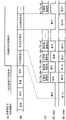
参照图4对本实施方式的电子笔3的电子笔电路300的动作进行说明。The operation of the
在本实施方式的电子笔电路300中,控制电路301在电子笔和位置检测传感器21没有成为静电耦合的状态时,切换开关电路305根据切换控制信号SW2(参照图4的(E))切换到端子R,将周边电极32通过切换开关电路305与信号接收电路303连接。然后,控制电路301根据来自信号接收电路303的源自位置检测传感器21的信号的接收的监视输出(参照图4的(A)),监视来自位置检测传感器21的信号的接收。此时,控制电路301根据切换控制信号SW1(参照图4的(D))使开关电路304断开。In the
此外,在本实施方式中,控制电路301及信号接收电路303不是始终执行从位置检测传感器接收的信号的监视,而是如图4的(B)的前半部分所示,仅在以规定的周期反复的间歇的信号接收监视期间执行。In addition, in the present embodiment, the
控制电路301以在根据来自信号接收电路303的监视输出检测到来自位置检测传感器21的信号的接收时,将电子笔电路300从待机状态切换为激活状态,并将来自电源部的电源电压供给到各部的方式进行控制。然后,如图4的(B)所示,控制电路301以如下方式进行控制,将电子笔电路300的动作模式以分时方式在信号接收模式与信号送出模式之间切换。在该情况下,分时控制从信号接收模式开始。The
在信号接收模式中,如图4的(E)所示,控制电路301根据切换控制信号SW2,将切换开关电路305切换到固定端子R侧。因此,信号接收电路303通过切换开关电路205接收由周边电极12接收到的来自位置检测传感器的信号,进行与该接收到的信号对应的解调等的处理,将该处理结果的信号发送到控制电路301。然后,在该信号接收模式下,如图4的(D)所示,控制电路301根据切换控制信号SW1断开开关电路304,不进行来自作为中心电极的芯体31的信号送出。In the signal reception mode, as shown in (E) of FIG. 4 , the
控制电路301根据来自信号接收电路203的信号,对从位置检测传感器接收到的信号进行解析,判断对方的位置检测装置的规格,并基于该判断结果,确定与对方的位置检测装置的位置检测传感器进行信号的交互的定时。然后,控制电路301将从信号发送电路202输出的信号的格式控制为与对方的位置检测装置的规格一致,在确定的定时进行与位置检测传感器的交互。The
另外,在该信号接收模式中,控制电路301在从信号接收电路303接收到经过位置检测传感器21并经由周边电极32发送来的来自信息处理装置2的信息时,还进行将接收到的信息存储于信息存储部34的处理。In addition, in this signal reception mode, when the
而且,在信号送出模式中,在本实施方式中,控制电路301以分时方式多次执行将位置检测用的突发信号、笔压信息及笔ID送出到位置检测装置侧的位置检测期间Ta、和电子笔1的倾斜角的检测用的倾斜检测期间Tb。Furthermore, in the signal sending mode, in the present embodiment, the
控制电路301在位置检测期间Ta,根据控制信号SW1(参照图4的(D)),使开关电路304接通,另外,切换开关电路305根据切换控制信号SW2(参照图4的(E))将可动端子M与固定端子G连接。因此,周边电极32与接地端子连接。In the position detection period Ta, the
而且,控制电路301在位置检测期间Ta,控制信号发送电路302,将包含用于位置检测装置中的位置检测的规定频率的位置检测用信号(突发信号)、与由笔压检测部3检测到的笔压对应的笔压信息以及笔ID的信号通过开关电路304供给到芯体31,通过静电电容耦合发送到位置检测传感器。此时,由于周边电极32与接地端子连接,因此相对于作为中心电极的芯体31,作为屏蔽电极起作用,防止向芯体31的噪声的混入。Then, during the position detection period Ta, the
在倾斜检测期间Tb中,控制电路301根据控制信号SW1(参照图4的(D)),使开关电路304断开,另外,切换开关电路305根据切换控制信号SW2(参照图4的(E))以使可动端子M与固定端子S连接的方式进行控制。然后,在该倾斜检测期间Tb,控制电路301以使从信号发送电路302产生电子笔3的倾斜角的检测用的突发信号并从周边电极32送出的方式进行控制。In the tilt detection period Tb, the
此外,在信息处理装置2的位置检测电路204,检测来自该周边电极32的信号的位置检测传感器21中的检测位置的分布,并根据该检测结果检测电子笔3的倾斜。In addition, the
[与局部检测区域AR1、AR2、AR3对应的功能处理的例子][Example of functional processing corresponding to local detection areas AR1, AR2, AR3]
在说明与局部检测区域AR1、AR2、AR3对应地设定的功能处理之前,对电子笔3的指示位置为书写输入检测区域AR0内时的信息处理装置2的处理动作进行说明。Before describing the functional processing set corresponding to the local detection areas AR1 , AR2 , and AR3 , the processing operation of the
即,在本实施方式中,当由位置检测电路204检测到电子笔3的指示位置在书写输入检测区域AR0内时,信息处理装置2的控制电路201将检测到的指示位置的信息作为书写输入信息存储在存储部207的与书写输入检测区域AR0对应的存储区域中。此时,在本实施方式中,从电子笔3发送来的笔压信息、笔ID也作为书写输入信息一并存储。然后,控制电路201生成基于检测到的指示位置的信息的书写痕迹的图像信息并供给到显示控制电路206。如图1及图2所示,显示控制电路206将该书写痕迹的图像Ps显示于显示设备22的显示画面上。而且,笔压信息反映在该书写痕迹的线的粗细等上进行显示。That is, in the present embodiment, when the
接下来,对在本实施方式中在信息处理装置2的位置检测传感器21的检测区域内与局部检测区域AR1、AR2、AR3对应地设定的功能处理的例子进行说明。Next, an example of functional processing set in the detection area of the
在该例中,对于局部检测区域AR1,设定了从存储部207读出此前在书写输入检测区域AR0检测到的书写输入信息并发送到电子笔3的功能。即,在该例中,在由位置检测电路204检测到电子笔3的指示位置在局部检测区域AR1内时,控制电路201从存储部207读出此前在书写输入检测区域AR0检测到的书写输入信息并供给到发送信息处理电路205。In this example, the local detection area AR1 is set with a function of reading out the writing input information detected in the writing input detection area AR0 so far from the
在该情况下,在该例子中,构成为从存储部207的与书写输入检测区域AR0对应的存储区域读出书写输入信息。因此,在该例中,不需要在存储部207中另外设置与局部检测区域AR1对应的存储区域,与书写输入检测区域AR0对应的存储区域也兼作与局部检测区域AR1对应的存储区域。此外,也可以在存储部207中设定与局部检测区域AR1对应的存储区域,将书写输入信息也存储在该设定的存储区域中,从该存储区域读出书写输入信息。In this case, in this example, the writing input information is read from the storage area corresponding to the writing input detection area AR0 of the
然后,控制电路201将切换开关电路203切换到端子T侧,并且控制导体选择电路202,使得在局部检测区域AR1中,选择具有交点的第一导体212Y及第二导体213X。由此,存储于存储部207的书写输入信息被向位于位置检测传感器21的局部检测区域AR1的电子笔3发送。在电子笔3中,利用周边电极32接收通过位置检测传感器21发送来的书写输入信息,并存储于存储部34中。Then, the
通过使用对该局部检测区域AR1设定的功能,能够将在信息处理装置2中通过电子笔3进行书写输入的信息移交给其他信息处理装置,继续进行书写输入。By using the function set to the local detection area AR1, the information input by the
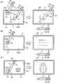
即,如图5的(A)的左侧所示,使用者在信息处理装置2的位置检测传感器21上的书写输入检测区域AR0中,通过电子笔3进行例如形成书写痕迹Ps的书写输入后,若将电子笔3的芯体31的指示位置移动到局部检测区域AR1,则信息处理装置2从位置检测传感器21的局部检测区域AR1将此前的书写输入信息发送到电子笔3的周边电极32,因此电子笔3通过周边电极32接收该书写输入信息并存储到存储部34中。That is, as shown on the left side of FIG. 5(A) , the user performs, for example, a writing input that forms a writing trace Ps with the
接下来,如图5的(A)的右侧所示,使用者如上所述那样将在存储部34中存储有书写输入信息的电子笔3携带到具备能够与近距离无线通信部35进行通信的通信部的其他信息处理装置2′的附近,使得在电子笔3与该信息处理装置2′之间进行近距离无线通信。于是,电子笔3读出存储于存储部34中的书写输入信息并发送到信息处理装置2′。因此,在信息处理装置2′中,能够基于从电子笔3接收到的书写输入信息,将书写痕迹Ps显示在其显示设备22′的显示画面上,使用者能够对信息处理装置2′的位置检测传感器21′进行与书写痕迹Ps连续的书写输入。Next, as shown on the right side of FIG. 5(A) , the user carries the
此外,电子笔3也可以不通过近距离无线通信部35,而是如图5的右侧由虚线所示那样,将存储于存储部34的书写输入信息从芯体31或周边电极32通过位置检测传感器21′发送到信息处理装置2′。In addition, the
在该情况下,信息处理装置2′在检测到位置检测传感器21′与电子笔3的电场耦合时,向电子笔3发送存储部34的存储信息的取得请求,接收根据该取得请求从电子笔3通过位置检测传感器21′发送来的信息。然后,电子笔3在从信息处理装置2′接收到存储部34的存储信息的取得请求时,判别是否存在向存储部34传送的存储信息,在存在传送的存储信息的情况下,从存储部34读出该存储信息并通过位置检测传感器21′发送,在不存在存储信息时,通过位置检测传感器21′发送该意思。In this case, when the information processing device 2' detects that the electric field coupling between the position detection sensor 21' and the
另外,电子笔3也可以构成为,不是在接收到来自信息处理装置2′的取得请求时,而是在检测到与信息处理装置2′的位置检测传感器21′的电场耦合时,将存储部34的存储信息通过位置检测传感器21′发送到信息处理装置2′。In addition, the
接下来,在该例中,对于局部检测区域AR2,设定有从存储部207读出与笔ID建立对应地存储的信息并发送到电子笔3的功能。在假定每个使用者使用不同的电子笔3的情况下,笔ID与使用者识别信息相同。因此,在该例中,将要向各个使用者传递的信息与各个使用者所使用的电子笔3的笔ID建立对应地预先存储于存储部207的与局部检测区域AR2对应的存储区域中。作为想要向使用者传递的信息,除了使用电子笔3与笔ID对应地指定由信息处理装置2管理的对方而输入的信息之外,也可以是通过通信部209取得的信息。在该情况下,在通过通信部209取得的信息中包含电子邮件的接收信息、即与笔ID对应地由信息处理装置2管理的发给接收者的接收信息。Next, in this example, a function of reading out the information stored in association with the pen ID from the
通过使用对该局部检测区域AR2设定的功能,能够从信息处理装置2向特定的电子笔3的使用者传送与该使用者建立对应地预先准备的信息。电子笔3的使用者能够利用其他信息处理装置2′显示并获知该传送的信息。By using the function set to the local detection area AR2, information prepared in advance in association with the user can be transmitted from the
即,如图5的(B)的左侧所示,当使用者在信息处理装置2的位置检测传感器21上将电子笔3的芯体31的指示位置移动到局部检测区域AR2时,信息处理装置2从位置检测传感器21的局部检测区域AR2将与该电子笔3的笔ID对应的信息发送到电子笔3的周边电极32,因此电子笔3通过周边电极32接收与该笔ID对应的信息,并存储在存储部34中。That is, as shown on the left side of FIG. 5(B) , when the user moves the pointed position of the
接下来,如图5的(B)的右侧所示,使用者将在存储部34中存储有与笔ID对应的信息的电子笔3携带到具备能够与近距离无线通信部35进行通信的通信部的其他信息处理装置2′的附近,使得在电子笔3与该信息处理装置2′之间进行近距离无线通信。于是,电子笔3读出存储于存储部34的信息并发送到信息处理装置2′。因此,在信息处理装置2′中,能够基于从电子笔3接收到的信息,将与笔ID对应的信息显示在其显示设备22′的显示画面上。因此,在信息处理装置2′中,使用者能够利用其他信息处理装置2′获知为使用者准备的信息。Next, as shown on the right side of FIG. 5(B) , the user carries the
此外,在图5的(B)的例子中,虽然省略了图示,但在该例的情况下,在信息处理装置2′具备位置检测传感器21′的情况下,电子笔3也可以不通过近距离无线通信部35,而从芯体31或周边电极32通过位置检测传感器21′将存储于存储部34的与笔ID对应的信息发送到信息处理装置2′。In addition, although illustration is abbreviate|omitted in the example of FIG.5(B), in the case of this example, when the information processing apparatus 2' is provided with the position detection sensor 21', the
接下来,在该例中,对于局部检测区域AR3,设定了从存储部207读出与规定的关键字建立对应地存储的信息并发送到电子笔3的功能。在该例中,将规定的1个或多个关键字与对应于该每个关键字的信息的对应信息预先存储在存储部207的与局部检测区域AR3对应的存储区域中。在该情况下,作为与关键字对应地存储的信息,可以是使用电子笔3输入的信息,也可以是通过通信部209取得的信息。Next, in this example, for the local detection area AR3, a function of reading out information stored in association with a predetermined keyword from the
通过使用对局部检测区域AR3设定的功能,能够从信息处理装置2将与关键字对应的信息传送到电子笔3。电子笔3的使用者能够利用其他信息处理装置2′显示并获知该传送的信息。By using the function set to the local detection area AR3, the information corresponding to the keyword can be transmitted from the
即,如图5的(C)的左侧所示,当使用者在信息处理装置2的位置检测传感器21上将电子笔3的芯体31的指示位置移动到局部检测区域AR3时,在该例中,信息处理装置2在与书写输入检测区域AR0对应的显示区域中显示提示关键字的选择输入的消息,并且虽然省略图示,但在与局部检测区域AR3对应的显示区域,显示存储于存储部207的关键字的一览。That is, as shown on the left side of FIG. 5(C) , when the user moves the pointed position of the
当通过电子笔3从该关键字的一览选择关键字时,信息处理装置2从位置检测传感器21的局部检测区域AR3将与该关键字对应的信息发送到电子笔3的周边电极32。电子笔3通过周边电极32接收与该选择的关键字对应的信息,并存储于存储部34中。此外,通过利用电子笔3选择多个关键字,信息处理装置2也可以将与该选择的多个关键字对应的信息发送到电子笔3,电子笔3将其存储到存储部34中。When a keyword is selected from the list of keywords by the
接下来,如图5的(C)的右侧所示,使用者将在存储部34中存储有与存储关键字对应的信息的电子笔3携带到具备能够与近距离无线通信部35进行通信的通信部的其他信息处理装置2′的附近,使得在电子笔3与该信息处理装置2′之间进行近距离无线通信。于是,电子笔3读出存储于存储部34的信息并发送到信息处理装置2′。因此,在信息处理装置2′中,能够基于从电子笔3接收到的信息,将与关键字对应的信息显示在其显示设备22′的显示画面上。因此,使用者可以利用其他信息处理装置2′获知与在信息处理装置2′中准备的关键字对应的信息。Next, as shown on the right side of FIG. 5(C) , the user carries the
此外,虽然省略了图示,但在图5的(C)的例子的情况下,在信息处理装置2′具备位置检测传感器21′的情况下,电子笔3也可以不通过近距离无线通信部35,而从芯体31或周边电极32通过位置检测传感器21′将存储于存储部34的与关键字对应的信息发送到信息处理装置2′。In addition, although illustration is omitted, in the case of the example of FIG. 5(C), when the information processing device 2' is provided with the position detection sensor 21', the
此外,通过利用电子笔3不是对局部检测区域AR1~AR3中的某一个而是对多个或者全部进行位置指示,能够在信息存储部34中存储与该位置指示的局部检测区域分别对应的信息的全部。In addition, by using the
此外,信息处理装置2′当然也可以不具有与信息处理装置2同样的结构。但是,作为传送书写输入信息的信息处理装置2′,当然最好具备位置检测传感器21′。另外,作为传送与图5的(B)的例子的笔ID对应的信息、与图5的(C)的例子的关键字对应的信息的信息处理装置2′,不需要具备位置检测传感器21′,只要至少具备具有用于显示这些信息的显示画面的显示设备22即可。In addition, it is needless to say that the
[电子笔3及信息处理装置2中的动作的说明][Description of operations in the
接下来,对用于实现以上那样的功能的电子笔3及信息处理装置2中的处理动作的流程进行说明。Next, the flow of processing operations in the
<电子笔3的动作例的说明><Description of an example of the operation of the
图6~图8是表示用于说明在电子笔3的电子笔电路300中实现包含以上说明的功能处理的动作的处理的流程的例子的流程图的图。该流程图的各步骤的动作由电子笔电路300的控制电路301进行。6 to 8 are diagrams showing flowcharts for explaining an example of the flow of processing for realizing the operation including the functional processing described above in the
即,控制电路301判别是否处于与信息处理装置2的位置检测传感器21进行电场耦合的状态(步骤S1)。电子笔3处于与信息处理装置2的位置检测传感器21进行电场耦合的状态的状态是能够相互交换信号的状态,不仅包括电子笔3的芯体31与位置检测传感器的检测面接触的状态,还包括检测面稍微离开而接近的悬停状态。That is, the
在该步骤S1下,当判别为处于与信息处理装置2的位置检测传感器21进行电场耦合的状态时,控制电路301判别是否是信号接收模式的期间(步骤S2)。在该步骤S2中,在判别为不是信号接收模式的期间时,控制电路301判别是否是信号送出模式的期间(步骤S3)。然后,在该步骤S3中,在判别为不是信号送出模式的期间时,控制电路301使处理返回步骤S1,重复从该步骤S1开始的处理。In this step S1, when it is determined that the
然后,在步骤S3中,在判别是信号送出模式的期间时,控制电路301判别是位置检测期间Ta还是倾斜检测期间Tb(图7的步骤S11)。在该步骤S11中,在判别为是位置检测期间Ta时,控制电路301以使开关电路304接通,使切换开关电路305与端子G连接的方式进行切换控制(步骤S12)。接着,控制电路301以从信号发送电路302将位置检测用信号、笔压信息、笔ID从作为中心电极的芯体31送出的方式进行控制(步骤S13)。在该步骤S13之后,控制电路301使处理返回步骤S1,重复从该步骤S1开始的处理。Then, in step S3, when it is determined that the period is the signal sending mode, the
在步骤S11中,在判别为是倾斜检测期间Tb时,控制电路301以使开关电路304断开,使切换开关电路305与端子S连接的方式进行切换控制(步骤S14)。接着,控制电路301以从信号发送电路302将倾斜检测用信号从周边电极32送出的方式进行控制(步骤S15)。在该步骤S15之后,控制电路301使处理返回步骤S1,重复从该步骤S1开始的处理。In step S11, when it is determined that it is the tilt detection period Tb, the
在图6的步骤S2中,在判别为是信号接收模式的期间时,控制电路301以使开关电路304断开,使切换开关电路305与端子R连接的方式进行切换控制(步骤S4)。接着,控制电路301基于信号接收电路303的输出,判别是否检测到接收信号(步骤S5)。在该步骤S5中,在判别为未检测到接收信号时,控制电路301使处理返回步骤S1,重复从该步骤S1开始的处理。In step S2 of FIG. 6 , when it is determined that it is in the signal reception mode, the
然后,在步骤S5中,在判别为检测到接收信号时,控制电路301接收并处理通过了位置检测传感器21及周边电极32的信号(步骤S6)。然后,控制电路301通过该步骤S6中的处理,判别接收信号是否是需要传送的信息(步骤S7)。根据接收信号是否是与信息处理装置2的规格对应的信号及定时控制信号来判断是否是需要传送的信息,在判别为接收信号不是与信息处理装置2的规格对应的信号及定时控制信号时,判别为是需要传送的信息。此外,也可以在来自信息处理装置2的信息中包含表示是否是需要传送的信息的信息,根据该信息,判别是否是电子笔3需要传送的信息。Then, in step S5, when it is determined that the reception signal has been detected, the
然后,在该步骤S7中,在判别为接收信号不是需要传送的信息,而是与信息处理装置2的规格对应的信号及定时控制信号时,控制电路301根据该接收信号,进行以使电子笔3的规格与信息处理装置2对应的方式进行控制并且控制分时处理的定时等、与接收信号对应的处理(步骤S8)。Then, in this step S7, when it is determined that the received signal is not information to be transmitted, but a signal and a timing control signal corresponding to the specifications of the
另外,在该步骤S7中,在判别为接收信号是需要传送的信息时,控制电路301进行将接收到的来自信息处理装置2的信息保存于存储部34的处理(步骤S9)。该在步骤S9之后,控制电路301使处理返回步骤S1,重复从该步骤S1开始的处理。In addition, in this step S7, when it is determined that the received signal is information to be transmitted, the
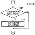
然后,在步骤S1中,在判别为未处于与信息处理装置2的位置检测传感器21进行电场耦合的状态时,控制电路301判别是否处于与其他装置进行近距离无线通信的配对状态(图8的步骤S21)。在该步骤S21中,在判别我未处于与其他装置进行近距离无线通信的配对状态时,控制电路301使处理返回步骤S1,重复从该步骤S1开始的处理。Then, in step S1, when it is determined that the electric field coupling with the
在步骤S21中,在判别为处于与其他装置进行近距离无线通信的配对状态时,控制电路301读出存储于信息存储部34的信息,并发送到配对状态的其他装置(步骤S22)。在发送结束后,控制电路301使处理返回步骤S1,重复从该步骤S1开始的处理。In step S21 , when it is determined that the paired state is in the short-range wireless communication with another device, the
<信息处理装置2的动作例的说明><Description of an example of operation of the
图9及图10是表示用于说明在信息处理装置2的处理电路200中用于实现包含以上说明的功能处理的动作的处理的流程的例子的流程图的图。该流程图的各步骤的动作由处理电路200的控制电路201进行。9 and 10 are diagrams showing flowcharts for explaining an example of the flow of processing for realizing the operation including the functional processing described above in the
控制电路201送出用于与电子笔3进行静电电容耦合的信号(包含定时信号、表示规格的信号)(步骤S31)。对于该信号的送出,从静电电容耦合的电子笔发送来位置检测用信号等的信号,因此控制电路201判别是否接收到来自电子笔3的信号(步骤S32),在判别为未接收到来自电子笔3的信号时,使处理返回步骤S31,重复该步骤S31以后的处理。The
在步骤S32中,在判别为接收到来自电子笔3的信号时,控制电路201进行接收信号的处理,即,进行位置检测传感器21上的电子笔3的指示位置的检测、电子笔3的倾斜的检测、笔压信息及笔ID的取得(步骤S33)。In step S32 , when it is determined that the signal from the
接下来,控制电路201判别检测到的电子笔3的指示位置是否为书写输入检测区域AR0内(步骤S34)。在该步骤S34中,在判别为检测到的电子笔3的指示位置在书写输入检测区域AR0内时,控制电路201将检测到的指示位置、电子笔3的倾斜角及取得的笔压信息及笔ID存储于存储部207中(步骤S35)。控制电路201在该步骤S35之后,使处理返回步骤S32,重复该步骤S32以后的处理。Next, the
在步骤S34中,在判别为检测到的电子笔3的指示位置在书写输入检测区域AR0内时,控制电路201判别检测到的电子笔3的指示位置是否在局部检测区域AR1内(步骤S36)。在该步骤S36中,在判别为检测到的电子笔3的指示位置在局部检测区域AR1内时,控制电路201从存储部207读出此前存储的电子笔3的指示位置、电子笔3的倾斜角、笔压信息及笔ID,从位置检测传感器21的局部检测区域AR1送出(步骤S37)。控制电路201在该步骤S37之后,使处理返回步骤S32,重复该步骤S32以后的处理。In step S34, when it is determined that the detected pointing position of the
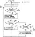
在步骤S36中,在判别为检测到的电子笔3的指示位置不在局部检测区域AR1内时,控制电路201判别检测到的电子笔3的指示位置是否在局部检测区域AR2内(图10的步骤S41)。在该步骤S41中,在判别为检测到的电子笔3的指示位置在局部检测区域AR2内时,控制电路201判别在存储部207中是否存储有与在步骤S33中取得的笔ID对应的信息(步骤S42)。In step S36, when it is determined that the detected pointing position of the
在该步骤S42中,在判别为在存储部207中存储有与在步骤S33中取得的笔ID对应的信息时,控制电路201从存储部207读出与该笔ID对应的信息,从位置检测传感器21的局部检测区域AR2送出(步骤S43)。控制电路201在该步骤S43之后,使处理返回步骤S32,重复该步骤S32以后的处理。另外,在步骤S42中,在判别为在存储部207中未存储有与在步骤S33中取得的笔ID对应的信息时,控制电路201也使处理返回步骤S32,重复该步骤S32以后的处理。In this step S42, when it is determined that the information corresponding to the pen ID acquired in step S33 is stored in the
另外,在步骤S41中,在判别为检测到的电子笔3的指示位置不在局部检测区域AR2内时,控制电路201判别检测到的电子笔3的指示位置是否在局部检测区域AR3内(步骤S44)。在该步骤S44中,在判别为检测到的电子笔3的指示位置在局部检测区域AR3内时,控制电路201在显示设备22的显示画面上显示可选择的关键字的一览和提示关键字的选择输入的消息(步骤S45)。In addition, in step S41, when it is determined that the detected pointing position of the
接下来,控制电路201判别是否接受了关键字的选择输入(步骤S46),在判别为接受了关键字的选择输入时,读出与所选择的关键字对应地存储于存储部207的信息,从位置检测传感器21的局部检测区域AR3送出(步骤S47)。控制电路201在该步骤S47之后,使处理返回步骤S32,重复该步骤S32以后的处理。另外,在步骤S44中,在判别为检测到的电子笔3的指示位置不在局部检测区域AR3内时,控制电路201也使处理返回步骤S32,重复该步骤S32以后的处理。Next, the
[第一实施方式的效果][Effects of the first embodiment]
如上所述,在上述的第一实施方式的信息处理系统1中,通过用电子笔3对预先设定在信息处理装置2的位置检测传感器21的检测区域内的局部检测区域进行位置指示,将与该局部检测区域建立对应地存储于存储部207的信息发送到电子笔3,并存储在电子笔3的信息存储部34中。As described above, in the
然后,通过使电子笔3的近距离无线通信部35与其他信息处理装置的近距离无线通信部配对,能够将存储于信息存储部34的信息发送到该其他信息处理装置。即,根据本实施方式的信息处理系统,能够将存储于信息处理装置1的存储部207的信息经由电子笔3传送到其他信息处理装置。因此,通过本实施方式的信息处理系统,能够进行各种的有益的信息传送。Then, by pairing the short-range
例如,在上述的第一实施方式中,通过与局部检测区域AR1建立对应地存储书写输入信息,能够经由电子笔3的信息存储部34将在信息处理装置2未写完的书写输入信息传送到其他信息处理装置。由此,能够接着在信息处理装置2未写完的书写输入信息,在其他信息处理装置进行书写输入,非常便利。For example, in the first embodiment described above, by storing the handwriting input information in association with the local detection area AR1, the handwriting input information that has not been written in the
另外,通过在局部检测区域AR2存储与笔ID建立对应的信息,能够将与电子笔3的笔ID建立对应的信息经由电子笔3的信息存储部34传送到其他信息处理装置。由此,能够容易地通过电子笔3传递想要传递给电子笔3的使用者的信息。In addition, by storing the information associated with the pen ID in the local detection area AR2 , the information associated with the pen ID of the
而且,通过在局部检测区域AR3存储与关键字建立对应的信息并且能够由电子笔3的使用者进行关键字的选择,能够经由电子笔3的信息存储部34将与使用者想要的关键字对应的信息传送到其他信息处理装置。Furthermore, by storing information associated with the keyword in the local detection area AR3 and enabling the user of the
[第一实施方式的变形例][Variation of the first embodiment]
此外,在上述的第一实施方式中,以信息处理装置2的存储部207不仅预先存储并保持书写输入信息,还预先存储并保持向电子笔3传递的信息的全部的方式进行了说明,但存储部也可以是通过通信部209连接的外部的装置的存储部。即,信息处理装置2也可以在通过电子笔指示了规定的局部检测区域时,将与被进行位置指示的局部检测区域对应的信息的取得请求发送到具备存储部的其他装置,取得根据该取得请求从其他装置发送来的信息,并发送到电子笔。In addition, in the above-described first embodiment, the
另外,在上述的实施方式中,与关键字建立对应的信息也预先存储于存储部207中,但也可以将由电子笔3选择的关键字、由电子笔3书写输入的关键字通过通信部209发送到因特网的检索站点,将从该检索站点发送来的检索结果发送到电子笔3。即,也可以构成为,与关键字对应的信息不预先存储,而将实时检索而取得的信息发送到电子笔。In addition, in the above-described embodiment, the information associated with the keywords is also stored in the
此外,作为向电子笔传送的信息,不限于上述的实施方式的显示信息,也可以是声音信息等。另外,也可以是规定的程序等。In addition, the information to be transmitted to the electronic pen is not limited to the display information of the above-described embodiment, and may be sound information or the like. In addition, a predetermined program etc. may be sufficient.
[第二实施方式][Second Embodiment]
在第一实施方式中,与信息处理装置连接的传感器使用了能够进行指示位置的检测的位置检测传感器,但也可以是不具有位置检测功能的传感器。第二实施方式是如下的例子,作为传感器,使用如下的传感器,通过,将电子笔等的指示操作装置的指示操作通过检测来自该指示操作装置的信号的接收来进行检测,并向信息处理装置送出,另外,能够将来自信息处理装置的信号向电子笔送出,但不具有位置检测功能。In the first embodiment, the sensor connected to the information processing device used a position detection sensor capable of detecting the indicated position, but a sensor without a position detection function may be used. The second embodiment is an example in which the following sensor is used as a sensor, and an instruction operation by an instruction operation device such as an electronic pen is detected by detecting the reception of a signal from the instruction operation device, and the instruction operation device is sent to the information processing device. In addition, it is possible to send a signal from the information processing device to the electronic pen, but it does not have a position detection function.
图11是用于说明该第二信息处理系统1A的结构例的概要的图。该第二实施方式的信息处理系统1A由信息处理装置2A和电子笔3A构成。FIG. 11 is a diagram for explaining an outline of a configuration example of the second
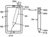
如图12所示,该例的电子笔3A是例如被称为智能手机的高性能移动电话终端5用的电子笔。该例的电子笔3A具有与第一实施方式的电子笔3相同的结构,省略该结构的说明。在以下的说明中,在电子笔3A中,对与第一实施方式的电子笔3相同的构成部分,分别附加后缀A来进行说明。As shown in FIG. 12 , the
虽然省略图示,但高性能移动电话终端5与显示画面5D重叠地具备静电电容方式的位置检测传感器5S,构成为能够与电子笔3A的芯体31A及周边电极32A进行电场耦合,能够进行电子笔3A的芯体31A的指示位置的检测、电子笔3A的倾斜角的检测。而且,高性能移动电话终端5具备近距离无线通信部,能够与电子笔3A的近距离无线通信部35A进行无线通信。而且,电子笔3A具备信息存储部34A,构成为能够将存储于该信息存储部34A的信息通过近距离无线通信部35A发送到信息处理装置2A。Although not shown, the high-performance
1个~多个传感器21A能够连接到该第二实施方式的信息处理系统1A中的信息处理装置2A。在图11的例子中,4个传感器21A与信息处理装置2A连接。One or
图13表示传感器21A的结构例,图13的(A)是该例的传感器21A的俯视图,图13的(B)是该例的传感器21A的剖视图。如图13的(A)及(B)所示,该例的传感器21A构成为,在上面侧形成开口的箱型的壳体214A内,配置在由绝缘物构成的基板211A的表面侧形成有第一电极212A、在背面侧形成有第二电极213A的传感器主体210A。FIG. 13 shows a configuration example of the
在图13的例子中,第一电极212A及第二电极213A分别由1个电极构成。但是,第一电极212A及第二电极213A也可以分别由多个电极构成。另外,第一电极212A及第二电极213A也可以形成在基板211A的表面侧的整个区域及背面侧的整个区域,而不是形成为图13的例子那样的线或带状。In the example of FIG. 13 , each of the
在该例子的传感器21A中,如图13的(A)及(B)所示,在该例中,传感器主体210A以基板211A的表面侧的第一电极212A侧向外部露出状态收纳在壳体214A内。而且,在该例的传感器21A中,如图13的(A)所示,与第一电极212A连接的端子215A和与第二电极213A连接的端子216A向壳体214A的外部导出而设置。In the
如图11所示,信息处理装置2A具备:具备多个输入输出端口的输入输出端口组221;与该输入输出端口组221连接的信号收发部222;与该信号收发部222连接的处理控制部223;及与该处理控制部223连接的存储部224。As shown in FIG. 11 , the
传感器21A能够与输入输出端口组的多个输入输出端口分别连接。对输入输出端口组的多个输入输出端口分别赋予端口编号。在该例中,4个传感器21A分别与端口编号PO1、PO2、PO3、PO4的输入输出端口连接。在该情况下,在图11的例子中,传感器21A的各个端子215A及216A通过由虚线表示的连接线分别与端口编号PO1、PO2、PO3、PO4的输入输出端口连接。The
此外,也可以将传感器21A与信息处理装置2A无线连接。在该情况下,在从传感器21A向信息处理装置2A发送的信息中,附加识别各传感器21A的识别信息(ID)。另外,在从信息处理装置2A向传感器21A发送的信息中,附加信息的接收目的地的传感器21A的识别信息(ID),在传感器21A中,根据附加于信息的识别信息(ID)来判别所接收的信息是否是发给自己的信息。In addition, the
此外,在以下的说明中,在需要区别与端口编号PO1、PO2、PO3、PO4的输入输出端口分别连接的传感器21A时,如图11所示,分别记载为传感器21A-1、传感器21A-2、传感器21A-3、传感器21-4。In addition, in the following description, when it is necessary to distinguish the
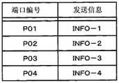
如图14所示,在信息处理装置2A的存储部224中,预先存储有与端口编号PO1、PO2、PO3、PO4分别对应的提供信息INFO1、INFO2、INFO3、INFO4。As shown in FIG. 14 , in the
在图11的例子中,传感器21A-1、传感器21A-2、传感器21A-3、传感器21-4配置于显示有日本地图的板4上,与该日本地图上设置有各个传感器21A-1、传感器21A-2、传感器21A-3、传感器21-4的地点相关联的主题信息、观光信息、其他的信息作为提供信息INFO1、INFO2、INFO3、INFO4预先存储于存储部224中。In the example of FIG. 11 , the
即,在图11的例子中,与传感器21A-1、传感器21A-2、传感器21A-3、传感器21-4分别对应地,例如,关于分别设置的地点“石川县”、“岐阜县”、“神奈川县”、“福岛县”的信息作为提供信息INFO1、INFO2、INFO3、INFO4预先存储于存储部224中。That is, in the example of FIG. 11, the
在该情况下,日本地图也可以将印刷在纸张上的地图作为粘贴在板状的板4上的地图,例如用双面胶带等将传感器21A-1、传感器21A-2、传感器21A-3、传感器21-4分别粘贴配置于纸张的地图上,也可以由显示设备构成板4,在显示有日本地图的显示画面上,例如用双面胶带等将传感器21A-1、传感器21A-2、传感器21A-3、传感器21-4分别粘贴配置于纸张的地图上。In this case, the map of Japan may be a map printed on paper as a map affixed to the plate-
此外,也可以在地图上附加或显示表示提供信息INFO1、INFO2、INFO3、INFO4存储在存储部224中的地点的编号等的标识符的标记,并且传感器21A-1、传感器21A-2、传感器21A-3、传感器21-4分别可识别地附加对应的编号,与地图分开配置。In addition, markers representing identifiers such as numbers of places where the information INFO1, INFO2, INFO3, and INFO4 are stored in the
如图13的(B)所示,当使电子笔3A的笔尖侧与4个传感器21A的某一个接触或者接近(悬停状态)时,来自电子笔3A的信号(位置检测用信号或者倾斜检测用信号)通过芯体31A或者周边电极32A向传感器21A送出。传感器21A通过与第一电极212A连接的端子215A和与第二电极213A连接的端子216A接收来自该电子笔3A的信号,并将其送出到信息处理装置2A。As shown in (B) of FIG. 13 , when the pen tip side of the
在信息处理装置2A中,来自传感器21A的信号通过输入输出端口组221中的与该传感器21A连接的输入输出端口被接收,被供给到信号收发部222。In the
信号收发部222在从输入输出端口组221接收到信号时,判别该接收信号是来自端口编号PO1~PO4中的哪一个的接收信号,并将该判别结果的端口编号的信息供给到处理控制部223。When a signal is received from the input/
处理控制部223当从信号收发部222接收到收到接收信号的端口编号的信息时,从存储部224读出并取得与收到接收信号的端口编号建立对应地存储的信息,将取得的信息发送到信号收发部222。When the
信号收发部222将从处理控制部223接收到的信息同输入输出端口组221中的收到接收信号的端口编号的输入输出端口发送到与该输入输出端口连接的传感器21A。The signal transmission/
传感器21A通过端子215A及216A接收来自信息处理装置2A的信息,并通过电场耦合从第一电极212A及第二电极213A向电子笔3A送出。The
如上所述,在电子笔3A中,在信号接收模式中,由周边电极32A接收来自传感器21A的信息,并存储于存储部34A中。然后,电子笔3A将存储于该存储部34A的信息如在图12中箭头所示那样,使用近距离无线通信部35A发送到高性能移动电话终端5,并在其显示画面5D上显示。As described above, in the
因此,在该第二实施方式的信息处理系统1A中,高性能移动电话终端5的使用者通过使电子笔3A的笔尖与自己想看信息的地点设置的传感器21A接触或者接近,能够从信息处理装置2A将与该地点相关联的信息存储于电子笔3A的信息存储部34A中。然后,使用者在这之后通过使电子笔3A和高性能移动电话终端5成为能够使用电子笔3A的近距离无线通信部35A进行无线通信的状态,能够将存储于电子笔3A的信息存储部34A的信息显示在高性能移动电话终端5的显示画面5D上来进行观看。Therefore, in the
此外,在该第二实施方式的情况下,如图12中由虚线所示,电子笔3A也可以不通过近距离无线通信部35,而从芯体31A或周边电极32A通过高性能移动电话终端5的位置检测传感器将存储于存储部34的信息发送到高性能移动电话终端5。In addition, in the case of the second embodiment, as shown by the dotted line in FIG. 12 , the
[第二实施方式的传感器的变形例][Variation of the sensor of the second embodiment]
图15表示在第二实施方式的信息处理系统1A中与信息处理装置2A连接的传感器的其他结构例。FIG. 15 shows another configuration example of a sensor connected to the
图15表示该例的传感器21B的结构例,图15的(A)是该例的传感器21B的剖视图。该例的传感器21B的俯视图与上述的传感器21A的俯视图相同。而且,图15的(B)是表示通过电子笔3A对该传感器21B进行了指示操作的状态的图。FIG. 15 shows a configuration example of the
如图15的(A)及(B)所示,该例的传感器21B构成为,在上面侧形成开口的箱型的壳体214B内,配置以隔着作为绝缘体的空气层相互分离且平行地相对的方式配置的2枚基板211B1及211B2。在该例中,至少基板211B1由具有挠性的部件构成。As shown in (A) and (B) of FIG. 15 , the
在这些基板211B1及基板211B2隔着空气层彼此相对的面形成有第一电极212B及第二电极213B。在图15的例子中,第一电极212B及第二电极213B分别由1个电极构成。但是,第一电极212B及第二电极213B也可以分别由多个电极构成。另外,第一电极212B及第二电极213B也可以形成在基板211B1及211B2的彼此相对的面的整个区域,而不是形成为图15的例子那样的线或带状。A
如图15的(A)及(B)所示,在该例中,传感器21B以基板211B1的与形成有第一电极212B的面相反一侧的面向外部露出的状态收纳在壳体214B内。而且,在传感器21B中,虽然省略图示,但与第二电极213B连接的端子向壳体214B的外部导出而设置。而且,传感器21B的与该第二电极213B连接的端子与信息处理装置2A的输入输出端口连接。As shown in FIGS. 15(A) and (B) , in this example, the
如图15的(B)所示,在该例的传感器21B中,当通过电子笔3A的笔尖进行指示操作时,挠性的基板211A1挠曲,成为第一电极212A与第二电极213A接触的状态。因此,从电子笔3A的芯体31A或者周边电极32A送出的信号通过第一电极212A和第二电极213A的接触点及传感器21B的端子被向信息处理装置2A发送。另外,从信息处理装置2A发送来的信息通过传感器2B的第一电极212A和第二电极213A的接触点被向电子笔3A的周边电极32A发送。其他结构及动作与上述的第二实施方式相同。As shown in FIG. 15(B) , in the
[指示操作装置的其他例子][Other examples of pointing operation device]
在以上的实施方式中,指示操作装置使用笔型的电子笔。但是,本发明中的指示操作装置不限于笔型的指示操作装置。In the above-described embodiments, a pen-type electronic pen is used as the instructing operation device. However, the pointing operation device in the present invention is not limited to a pen-type pointing operation device.
图16表示指示操作装置其他例子的结构例。该图16的例子的指示操作装置不是笔型,在该例中,是长方体形状的包型的结构。图16的(A)是该例的指示操作装置2C的侧视图,图16的(B)是该例的指示操作装置3B的仰视图。FIG. 16 shows a configuration example of another example of the pointing operation device. The pointing operation device in the example of FIG. 16 is not a pen type, but in this example has a cuboid-shaped bag-type structure. FIG. 16(A) is a side view of the pointing operation device 2C of this example, and FIG. 16(B) is a bottom view of the
为了容易理解该例的指示操作装置3B的结构,在指示操作装置3B中,对与上述的第一实施方式中的电子笔3的构成要素相同的功能部分,对相同的参照编号附加后缀B来进行说明。In order to facilitate the understanding of the configuration of the
如图16的(A)及(B)所示,该例的指示操作装置3B在矩形的框体30B的内部具备电子电路300B、信息存储部34B、近距离无线通信部35B。而且,指示操作装置3B以从矩形的框体30B的底面30Ba向与该底面30Ba正交的方向突出的方式设置有第一电极31B。第一电极31B具备圆盘状的形状,并且为向外部突出的端面以圆顶状鼓出的形状。另外,指示操作装置3B以从矩形的框体30B的底面30Ba露出的状态配置有以包围第一电极31B的周围的方式构成为环状的第二电极32B。As shown in FIGS. 16(A) and (B) , the
该例的指示操作装置3B的电子电路300B具备产生从第一电极31B或第二电极32B送出的信号的信号产生电路,并且具备将由第一电极31B或第二电极32B接收到的信息存储于信息存储部34B中的处理功能。在电子电路300中,构成为来自信号产生电路的信号的送出和来自信息处理装置的信息的接收与上述的实施方式同样地,通过分时控制进行。The
此外,在代替第一实施方式的信息处理系统的电子笔3而使用该例的指示操作装置3B的情况下,来自信号产生电路的信号从第一电极31B或第二电极32B的任一方或从这双方送出,并且在从信息处理装置经由传感器接收的情况下,通过第二电极32B接收。Further, when the
而且,在将该例的指示操作装置3B在第二实施方式的信息处理系统1A中使用的情况下,在不将该指示操作装置3B作为位置检测传感器中的位置指示用途使用的情况下,来自信号产生电路的信号可以从第一电极31B或第二电极32B中的任一方送出,也可以从这双方送出。另外,在从信息处理装置经由传感器接收的情况下,可以由第一电极31B或第二电极32B中的任一方接收,也可以由这双方接收。Furthermore, when the
此外,在该例的指示操作装置3B中,当然也可以设置检测对第一电极31B施加的压力的压力检测部、存储与笔ID对应的装置识别信息的ID存储部,包含在发送信号中。In addition, in the
[其他实施方式或变形例][Other Embodiments or Modifications]
此外,作为指示操作装置的送出用部,在上述的实施方式中,使用近距离无线通信部来构成,但也可以使用其他无线通信单元。另外,作为指示操作装置的送出用部,不限于无线通信单元,例如也可以在电子笔3、3A或者指示操作装置3B设置用于将存储于信息存储部的信息向外部送出的USB(Universal Sirial Bus)端子等的输出端子。In addition, in the above-mentioned embodiment, as the sending part of the instruction operation device, the short-range wireless communication part is used, but other wireless communication means may be used. In addition, the sending unit of the instruction operation device is not limited to the wireless communication unit. For example, the
标号说明Label description
1、1A…信息处理系统,2、2A…信息处理装置,3、3A…电子笔,3B…指示操作装置,21…位置检测传感器,21A…传感器,31、31A…芯体,32、32A…周边电极,31B…第一电极,32B…第二电极,34、34A、34B…信息存储部,35、35A、35B…近距离无线通信部。1, 1A...information processing system, 2, 2A...information processing device, 3, 3A...electronic pen, 3B...pointing operation device, 21...position detection sensor, 21A...sensor, 31, 31A...core, 32, 32A... Peripheral electrodes, 31B...first electrodes, 32B...second electrodes, 34, 34A, 34B...information storage units, 35, 35A, 35B...short-range wireless communication units.
Claims (17)
Translated fromChineseApplications Claiming Priority (3)
| Application Number | Priority Date | Filing Date | Title |
|---|---|---|---|
| JP2020033022 | 2020-02-28 | ||
| JP2020-033022 | 2020-02-28 | ||
| PCT/JP2021/005137WO2021172033A1 (en) | 2020-02-28 | 2021-02-12 | Information inputting/outputting system |
Publications (1)
| Publication Number | Publication Date |
|---|---|
| CN114930275Atrue CN114930275A (en) | 2022-08-19 |
Family
ID=77491465
Family Applications (1)
| Application Number | Title | Priority Date | Filing Date |
|---|---|---|---|
| CN202180008325.2APendingCN114930275A (en) | 2020-02-28 | 2021-02-12 | Information input/output system |
Country Status (4)
| Country | Link |
|---|---|
| US (3) | US11789549B2 (en) |
| JP (2) | JP7576078B2 (en) |
| CN (1) | CN114930275A (en) |
| WO (1) | WO2021172033A1 (en) |
Citations (9)
| Publication number | Priority date | Publication date | Assignee | Title |
|---|---|---|---|---|
| CN1838549A (en)* | 2005-03-25 | 2006-09-27 | 索尼株式会社 | Information processing system, information processing apparatus, methods, program and recording medium |
| JP2016095833A (en)* | 2015-08-21 | 2016-05-26 | 株式会社ワコム | Position indicator |
| JP2016153954A (en)* | 2015-02-20 | 2016-08-25 | 株式会社ワコム | Position indicator, signal processing circuit, signal supply control method, and signal processing method |
| WO2016171114A1 (en)* | 2015-04-20 | 2016-10-27 | 株式会社ワコム | Method using active stylus and sensor controller, sensor controller, and active stylus |
| US20160320918A1 (en)* | 2014-01-22 | 2016-11-03 | Wacom Co., Ltd. | Position indicator, position detecting device, position detecting circuit, and position detecting method |
| US20170228049A1 (en)* | 2014-11-17 | 2017-08-10 | Wacom Co., Ltd. | Position indicator |
| WO2018225358A1 (en)* | 2017-06-06 | 2018-12-13 | 株式会社ワコム | Position indicator |
| CN109564479A (en)* | 2016-08-22 | 2019-04-02 | 株式会社和冠 | Electronic pen, position detecting device and information processing unit |
| CN109643171A (en)* | 2016-09-01 | 2019-04-16 | 株式会社和冠 | Touch control pen, sensor controller and electronic ruler |
Family Cites Families (18)
| Publication number | Priority date | Publication date | Assignee | Title |
|---|---|---|---|---|
| JPH09179678A (en) | 1995-12-26 | 1997-07-11 | Pentel Kk | Coordinate input device with built-in CCD unit |
| JP2003323455A (en) | 2002-05-08 | 2003-11-14 | Nippon Telegr & Teleph Corp <Ntt> | Related information providing device, related information providing method, program, and recording medium recording this program |
| US20060192772A1 (en)* | 2005-02-28 | 2006-08-31 | Ko Kambayashi | Data control pen device |
| JP2007072584A (en)* | 2005-09-05 | 2007-03-22 | Sony Corp | Handwriting recording system, position information generation apparatus, method and program |
| TWI310136B (en)* | 2005-12-20 | 2009-05-21 | Wistron Corp | Method for transmitting files between different computers |
| JP5098267B2 (en)* | 2006-09-25 | 2012-12-12 | 富士ゼロックス株式会社 | WRITING INFORMATION PROCESSING DEVICE, WRITING INFORMATION PROCESSING METHOD, AND PROGRAM |
| JP2008181510A (en)* | 2006-12-28 | 2008-08-07 | Order-Made Souyaku Co Ltd | A system for collecting and managing handwritten written information using a digital pen |
| JP5440397B2 (en)* | 2010-06-01 | 2014-03-12 | 大日本印刷株式会社 | Information processing system and program |
| TWI474221B (en)* | 2011-08-24 | 2015-02-21 | Dexin Corp | Wireless transmission method and system for stylus with wireless storage and forwarding capability |
| US9265074B2 (en)* | 2011-10-06 | 2016-02-16 | Qualcomm Incorporated | Pen-based content transfer system and method thereof |
| CN104603763B (en)* | 2012-08-23 | 2018-06-05 | 三星电子株式会社 | Information transferring method and system, device and its computer readable recording medium storing program for performing |
| KR102219857B1 (en)* | 2014-03-18 | 2021-02-24 | 삼성전자주식회사 | An electronic device and operating method thereof |
| US9733731B2 (en)* | 2014-05-12 | 2017-08-15 | Atmel Corporation | Timing synchronization of active stylus and touch sensor |
| JP6472196B2 (en)* | 2014-09-17 | 2019-02-20 | 株式会社ワコム | Sensor signal processing circuit and sensor signal processing method |
| EP3267293B1 (en)* | 2015-03-02 | 2019-09-18 | Wacom Co., Ltd. | Active capacitive stylus, sensor controller, system comprising these, and method executed by these |
| US10324544B2 (en)* | 2016-12-27 | 2019-06-18 | Wacom Co., Ltd. | Hand-written information process apparatus, hand-written information processing method and hand-written information processing program |
| US20190324560A1 (en)* | 2018-04-24 | 2019-10-24 | Jamie Wilson-Haynes | Electronic stylus pen |
| CN112106014B (en) | 2018-07-06 | 2024-03-12 | 株式会社和冠 | Active pen and sensor integrated circuit |
- 2021
- 2021-02-12CNCN202180008325.2Apatent/CN114930275A/enactivePending
- 2021-02-12JPJP2022503255Apatent/JP7576078B2/enactiveActive
- 2021-02-12WOPCT/JP2021/005137patent/WO2021172033A1/ennot_activeCeased
- 2022
- 2022-06-15USUS17/841,486patent/US11789549B2/enactiveActive
- 2023
- 2023-09-12USUS18/465,850patent/US12099666B2/enactiveActive
- 2024
- 2024-08-22USUS18/812,928patent/US12429963B2/enactiveActive
- 2024-10-18JPJP2024182409Apatent/JP2025010586A/enactivePending
Patent Citations (9)
| Publication number | Priority date | Publication date | Assignee | Title |
|---|---|---|---|---|
| CN1838549A (en)* | 2005-03-25 | 2006-09-27 | 索尼株式会社 | Information processing system, information processing apparatus, methods, program and recording medium |
| US20160320918A1 (en)* | 2014-01-22 | 2016-11-03 | Wacom Co., Ltd. | Position indicator, position detecting device, position detecting circuit, and position detecting method |
| US20170228049A1 (en)* | 2014-11-17 | 2017-08-10 | Wacom Co., Ltd. | Position indicator |
| JP2016153954A (en)* | 2015-02-20 | 2016-08-25 | 株式会社ワコム | Position indicator, signal processing circuit, signal supply control method, and signal processing method |
| WO2016171114A1 (en)* | 2015-04-20 | 2016-10-27 | 株式会社ワコム | Method using active stylus and sensor controller, sensor controller, and active stylus |
| JP2016095833A (en)* | 2015-08-21 | 2016-05-26 | 株式会社ワコム | Position indicator |
| CN109564479A (en)* | 2016-08-22 | 2019-04-02 | 株式会社和冠 | Electronic pen, position detecting device and information processing unit |
| CN109643171A (en)* | 2016-09-01 | 2019-04-16 | 株式会社和冠 | Touch control pen, sensor controller and electronic ruler |
| WO2018225358A1 (en)* | 2017-06-06 | 2018-12-13 | 株式会社ワコム | Position indicator |
Also Published As
| Publication number | Publication date |
|---|---|
| JP7576078B2 (en) | 2024-10-30 |
| WO2021172033A1 (en) | 2021-09-02 |
| US20240004486A1 (en) | 2024-01-04 |
| JPWO2021172033A1 (en) | 2021-09-02 |
| JP2025010586A (en) | 2025-01-22 |
| US11789549B2 (en) | 2023-10-17 |
| US12429963B2 (en) | 2025-09-30 |
| US12099666B2 (en) | 2024-09-24 |
| US20240411388A1 (en) | 2024-12-12 |
| US20220308682A1 (en) | 2022-09-29 |
Similar Documents
| Publication | Publication Date | Title |
|---|---|---|
| US12333092B2 (en) | Stylus and color information transmitting method | |
| TWI685774B (en) | Position pointer | |
| US9880734B2 (en) | Handwritten information inputting device and portable electronic apparatus including handwritten information inputting device | |
| TW201636788A (en) | Position pointer, signal processing circuit, signal supply controlling method and signal processing method | |
| WO2015102069A1 (en) | Operating device | |
| TW201805774A (en) | Electronic pen and position detection system | |
| CN113076051A (en) | Slave control terminal synchronization method, device, terminal and storage medium | |
| CN114930275A (en) | Information input/output system | |
| CN113949692A (en) | Address allocation method and device, electronic equipment and computer readable storage medium | |
| CN110764808A (en) | Client upgrade detection method and device and computer readable storage medium | |
| CN110991909A (en) | Teaching progress reminding method and device | |
| JP6719001B2 (en) | Position indicator and signal processing device | |
| JP7457694B2 (en) | information processing equipment | |
| JPWO2021172033A5 (en) | ||
| JP7144584B2 (en) | Electronic pen and position detection system | |
| CN120429254A (en) | Addressing method, apparatus, device and readable storage medium | |
| US20190325169A1 (en) | Data communication method between a stylus and a tablet computer | |
| HK40068786A (en) | Method for connecting stylus pen and electronic device | |
| JPWO2020202629A5 (en) |
Legal Events
| Date | Code | Title | Description |
|---|---|---|---|
| PB01 | Publication | ||
| PB01 | Publication | ||
| SE01 | Entry into force of request for substantive examination | ||
| SE01 | Entry into force of request for substantive examination |