CN114929547A - Rail vehicle with cooling and air conditioning device - Google Patents
Rail vehicle with cooling and air conditioning deviceDownload PDFInfo
- Publication number
- CN114929547A CN114929547ACN202080092453.5ACN202080092453ACN114929547ACN 114929547 ACN114929547 ACN 114929547ACN 202080092453 ACN202080092453 ACN 202080092453ACN 114929547 ACN114929547 ACN 114929547A
- Authority
- CN
- China
- Prior art keywords
- heat exchanger
- coolant
- cooling
- refrigerant
- circuit
- Prior art date
- Legal status (The legal status is an assumption and is not a legal conclusion. Google has not performed a legal analysis and makes no representation as to the accuracy of the status listed.)
- Pending
Links
- 238000001816coolingMethods0.000titleclaimsabstractdescription172
- 238000004378air conditioningMethods0.000titleclaimsabstractdescription100
- 239000002826coolantSubstances0.000claimsabstractdescription227
- 239000003507refrigerantSubstances0.000claimsabstractdescription169
- 238000004146energy storageMethods0.000claimsabstractdescription35
- 239000007788liquidSubstances0.000claimsabstractdescription15
- 101100239079Arabidopsis thaliana MUR3 geneProteins0.000claimsdescription29
- 238000005057refrigerationMethods0.000claimsdescription28
- 101100230101Arabidopsis thaliana GRV2 geneProteins0.000claimsdescription24
- 238000002360preparation methodMethods0.000claims1
- 239000003570airSubstances0.000description67
- XLYOFNOQVPJJNP-UHFFFAOYSA-NwaterSubstancesOXLYOFNOQVPJJNP-UHFFFAOYSA-N0.000description10
- 230000006835compressionEffects0.000description8
- 238000007906compressionMethods0.000description8
- 238000010438heat treatmentMethods0.000description7
- 238000011144upstream manufacturingMethods0.000description6
- 230000033228biological regulationEffects0.000description5
- 239000012080ambient airSubstances0.000description3
- 230000000694effectsEffects0.000description3
- 238000001704evaporationMethods0.000description3
- 230000008020evaporationEffects0.000description3
- 239000002918waste heatSubstances0.000description3
- 230000005494condensationEffects0.000description2
- 238000009833condensationMethods0.000description2
- 238000010616electrical installationMethods0.000description2
- 238000005265energy consumptionMethods0.000description2
- 239000005431greenhouse gasSubstances0.000description2
- 230000003137locomotive effectEffects0.000description2
- 230000007704transitionEffects0.000description2
- 230000003213activating effectEffects0.000description1
- 230000004913activationEffects0.000description1
- 229910052782aluminiumInorganic materials0.000description1
- XAGFODPZIPBFFR-UHFFFAOYSA-NaluminiumChemical compound[Al]XAGFODPZIPBFFR-UHFFFAOYSA-N0.000description1
- 230000008859changeEffects0.000description1
- 239000003795chemical substances by applicationSubstances0.000description1
- 238000010276constructionMethods0.000description1
- 230000001276controlling effectEffects0.000description1
- 230000006735deficitEffects0.000description1
- 230000001419dependent effectEffects0.000description1
- 238000010586diagramMethods0.000description1
- 238000007599dischargingMethods0.000description1
- 230000005611electricityEffects0.000description1
- 230000007613environmental effectEffects0.000description1
- 230000002349favourable effectEffects0.000description1
- 239000007789gasSubstances0.000description1
- 238000009434installationMethods0.000description1
- 238000012423maintenanceMethods0.000description1
- 239000000463materialSubstances0.000description1
- 229910052751metalInorganic materials0.000description1
- 239000002184metalSubstances0.000description1
- 238000000034methodMethods0.000description1
- 230000008569processEffects0.000description1
- 230000009467reductionEffects0.000description1
- 230000001105regulatory effectEffects0.000description1
- 238000000926separation methodMethods0.000description1
- 230000000087stabilizing effectEffects0.000description1
- 239000013589supplementSubstances0.000description1
- 230000001629suppressionEffects0.000description1
- 238000004804windingMethods0.000description1
Images


Classifications
- B—PERFORMING OPERATIONS; TRANSPORTING
- B60—VEHICLES IN GENERAL
- B60L—PROPULSION OF ELECTRICALLY-PROPELLED VEHICLES; SUPPLYING ELECTRIC POWER FOR AUXILIARY EQUIPMENT OF ELECTRICALLY-PROPELLED VEHICLES; ELECTRODYNAMIC BRAKE SYSTEMS FOR VEHICLES IN GENERAL; MAGNETIC SUSPENSION OR LEVITATION FOR VEHICLES; MONITORING OPERATING VARIABLES OF ELECTRICALLY-PROPELLED VEHICLES; ELECTRIC SAFETY DEVICES FOR ELECTRICALLY-PROPELLED VEHICLES
- B60L1/00—Supplying electric power to auxiliary equipment of vehicles
- B—PERFORMING OPERATIONS; TRANSPORTING
- B60—VEHICLES IN GENERAL
- B60H—ARRANGEMENTS OF HEATING, COOLING, VENTILATING OR OTHER AIR-TREATING DEVICES SPECIALLY ADAPTED FOR PASSENGER OR GOODS SPACES OF VEHICLES
- B60H1/00—Heating, cooling or ventilating [HVAC] devices
- B60H1/00357—Air-conditioning arrangements specially adapted for particular vehicles
- B60H1/00371—Air-conditioning arrangements specially adapted for particular vehicles for vehicles carrying large numbers of passengers, e.g. buses
- B—PERFORMING OPERATIONS; TRANSPORTING
- B60—VEHICLES IN GENERAL
- B60H—ARRANGEMENTS OF HEATING, COOLING, VENTILATING OR OTHER AIR-TREATING DEVICES SPECIALLY ADAPTED FOR PASSENGER OR GOODS SPACES OF VEHICLES
- B60H1/00—Heating, cooling or ventilating [HVAC] devices
- B60H1/32—Cooling devices
- B60H1/3204—Cooling devices using compression
- B60H1/3228—Cooling devices using compression characterised by refrigerant circuit configurations
- B60H1/32284—Cooling devices using compression characterised by refrigerant circuit configurations comprising two or more secondary circuits, e.g. at evaporator and condenser side
- B—PERFORMING OPERATIONS; TRANSPORTING
- B60—VEHICLES IN GENERAL
- B60L—PROPULSION OF ELECTRICALLY-PROPELLED VEHICLES; SUPPLYING ELECTRIC POWER FOR AUXILIARY EQUIPMENT OF ELECTRICALLY-PROPELLED VEHICLES; ELECTRODYNAMIC BRAKE SYSTEMS FOR VEHICLES IN GENERAL; MAGNETIC SUSPENSION OR LEVITATION FOR VEHICLES; MONITORING OPERATING VARIABLES OF ELECTRICALLY-PROPELLED VEHICLES; ELECTRIC SAFETY DEVICES FOR ELECTRICALLY-PROPELLED VEHICLES
- B60L3/00—Electric devices on electrically-propelled vehicles for safety purposes; Monitoring operating variables, e.g. speed, deceleration or energy consumption
- B60L3/0023—Detecting, eliminating, remedying or compensating for drive train abnormalities, e.g. failures within the drive train
- B60L3/0046—Detecting, eliminating, remedying or compensating for drive train abnormalities, e.g. failures within the drive train relating to electric energy storage systems, e.g. batteries or capacitors
- B—PERFORMING OPERATIONS; TRANSPORTING
- B60—VEHICLES IN GENERAL
- B60L—PROPULSION OF ELECTRICALLY-PROPELLED VEHICLES; SUPPLYING ELECTRIC POWER FOR AUXILIARY EQUIPMENT OF ELECTRICALLY-PROPELLED VEHICLES; ELECTRODYNAMIC BRAKE SYSTEMS FOR VEHICLES IN GENERAL; MAGNETIC SUSPENSION OR LEVITATION FOR VEHICLES; MONITORING OPERATING VARIABLES OF ELECTRICALLY-PROPELLED VEHICLES; ELECTRIC SAFETY DEVICES FOR ELECTRICALLY-PROPELLED VEHICLES
- B60L58/00—Methods or circuit arrangements for monitoring or controlling batteries or fuel cells, specially adapted for electric vehicles
- B60L58/10—Methods or circuit arrangements for monitoring or controlling batteries or fuel cells, specially adapted for electric vehicles for monitoring or controlling batteries
- B60L58/24—Methods or circuit arrangements for monitoring or controlling batteries or fuel cells, specially adapted for electric vehicles for monitoring or controlling batteries for controlling the temperature of batteries
- B60L58/26—Methods or circuit arrangements for monitoring or controlling batteries or fuel cells, specially adapted for electric vehicles for monitoring or controlling batteries for controlling the temperature of batteries by cooling
- B—PERFORMING OPERATIONS; TRANSPORTING
- B61—RAILWAYS
- B61C—LOCOMOTIVES; MOTOR RAILCARS
- B61C3/00—Electric locomotives or railcars
- B61C3/02—Electric locomotives or railcars with electric accumulators
- B—PERFORMING OPERATIONS; TRANSPORTING
- B61—RAILWAYS
- B61D—BODY DETAILS OR KINDS OF RAILWAY VEHICLES
- B61D27/00—Heating, cooling, ventilating, or air-conditioning
- B61D27/0018—Air-conditioning means, i.e. combining at least two of the following ways of treating or supplying air, namely heating, cooling or ventilating
- B—PERFORMING OPERATIONS; TRANSPORTING
- B60—VEHICLES IN GENERAL
- B60H—ARRANGEMENTS OF HEATING, COOLING, VENTILATING OR OTHER AIR-TREATING DEVICES SPECIALLY ADAPTED FOR PASSENGER OR GOODS SPACES OF VEHICLES
- B60H1/00—Heating, cooling or ventilating [HVAC] devices
- B60H1/00271—HVAC devices specially adapted for particular vehicle parts or components and being connected to the vehicle HVAC unit
- B60H1/00278—HVAC devices specially adapted for particular vehicle parts or components and being connected to the vehicle HVAC unit for the battery
- B—PERFORMING OPERATIONS; TRANSPORTING
- B60—VEHICLES IN GENERAL
- B60H—ARRANGEMENTS OF HEATING, COOLING, VENTILATING OR OTHER AIR-TREATING DEVICES SPECIALLY ADAPTED FOR PASSENGER OR GOODS SPACES OF VEHICLES
- B60H1/00—Heating, cooling or ventilating [HVAC] devices
- B60H1/00271—HVAC devices specially adapted for particular vehicle parts or components and being connected to the vehicle HVAC unit
- B60H2001/00307—Component temperature regulation using a liquid flow
Landscapes
- Engineering & Computer Science (AREA)
- Mechanical Engineering (AREA)
- Power Engineering (AREA)
- Transportation (AREA)
- Life Sciences & Earth Sciences (AREA)
- Sustainable Development (AREA)
- Sustainable Energy (AREA)
- Physics & Mathematics (AREA)
- Thermal Sciences (AREA)
- Air-Conditioning For Vehicles (AREA)
- Cooling, Air Intake And Gas Exhaust, And Fuel Tank Arrangements In Propulsion Units (AREA)
Abstract
Description
Translated fromChinese本发明涉及一种带有储能装置的轨道车辆,在所述储能装置中可以储存电能以供应轨道车辆的牵引装置,所述轨道车辆还带有冷却装置,所述冷却装置用于冷却所述储能装置。本发明还涉及一种用于轨道车辆的冷却和空调装置。The invention relates to a rail vehicle with an energy storage device in which electrical energy can be stored for supplying a traction device of the rail vehicle, the rail vehicle further comprising a cooling device for cooling the energy storage device. The invention also relates to a cooling and air conditioning device for rail vehicles.
通过例如架空线或第三轨形式的外部电源提供电能的轨道车辆基本上依靠路网的完全电气化。为了能够额外在未完全电气化的线路上使用这些轨道车辆,它们越来越多地配备了储能装置,即所谓的牵引电池。储存在这些牵引电池中的电能在此用于在没有电气化的路段上行驶时供应驱动组件,必要时供应轨道车辆的辅助运行。牵引电池的充电可以例如在电气化的路段上行驶期间进行,或在尤其布置在车站区域中的专门的充电站处进行。Rail vehicles powered by external power sources, eg in the form of overhead lines or third rails, essentially rely on the complete electrification of the road network. In order to be able to additionally use these rail vehicles on lines that are not fully electrified, they are increasingly equipped with energy storage devices, so-called traction batteries. The electrical energy stored in these traction batteries is used here to supply drive components and, if necessary, auxiliary operation of the rail vehicle, when driving on non-electrified road sections. The charging of the traction battery can take place, for example, during driving on electrified road sections or at special charging stations arranged in particular in the station area.
牵引电池通常由多个相互电连接的电池单池或电池单池的模块构成,所述电池单池具有高的功率和能量密度。电池单池的长使用寿命在带有长达30年的期望使用寿命的轨道车辆中特别重要,为了实现电池单池的长使用寿命,电池单池必须在定义的温度段内运行,其中,所述温度段尤其取决于电池单池的材料。因此,尤其在环境温度较高时需要对电池单池冷却,以便将其温度保持在所述定义的温度段内的值。在充放电过程中电池单池本身也产生热,这也需相应地排出。Traction batteries generally consist of a plurality of electrically interconnected battery cells or modules of battery cells, which have a high power and energy density. A long service life of the battery cells is particularly important in rail vehicles with an expected service life of up to 30 years. In order to achieve a long service life of the battery cells, the battery cells must be operated within a defined temperature range, where all the This temperature range depends in particular on the material of the battery cells. It is therefore necessary to cool the battery cells, especially at high ambient temperatures, in order to keep their temperature within the defined temperature range. The battery cells themselves also generate heat during the charging and discharging process, which also needs to be dissipated accordingly.
电池单池或者模块的冷却通过冷却装置完成,例如通过与电池单池或者单池模块的壳体连接的冷却体完成。该冷却体例如布置在冷却剂回路中,该冷却剂回路通过循环的液态冷却剂将热量从电池单池或者冷却体排出。为了冷却例如水基的冷却剂本身可以设置基于压缩制冷机原理的制冷机。然而这种仅用于冷却牵引电池的制冷机不利地导致高成本,以及在集成到牵引电池的容器中时导致在轨道车辆上用于该容器的空间要求增加。The cooling of the battery cells or modules is carried out by means of cooling devices, for example by means of cooling bodies connected to the housings of the battery cells or cell modules. The cooling body is arranged, for example, in a coolant circuit which dissipates heat from the battery cells or the cooling body by means of circulating liquid coolant. Refrigerators based on the principle of compression refrigerators can be provided for cooling eg water-based coolants themselves. However, such refrigerators, which are only used for cooling the traction battery, disadvantageously lead to high costs and, when integrated into the container of the traction battery, an increased space requirement for the container on the rail vehicle.
为了减小成本和空间需求,文献DE 10 2017 223 214 A1已经建议,将用于冷却轨道车辆的乘客舱的空调装置的冷却剂回路与用于冷却轨道车辆的牵引电池的冷却剂回路通过额外的热交换器耦连,以此有利地取消用于牵引电池的单独的制冷机。In order to reduce costs and space requirements, document DE 10 2017 223 214 A1 already proposes to combine the coolant circuit of the air conditioning unit for cooling the passenger compartment of the rail vehicle with the coolant circuit for cooling the traction battery of the rail vehicle by an additional The heat exchanger is coupled, whereby a separate refrigerator for the traction battery is advantageously eliminated.
尤其对欧盟关于氟化温室气体的法规Nr.517/2014,也称为F-Gas法规的实施要求改变压缩制冷机中使用的冷却剂,所述冷却剂尤其用于轨道车辆的内部空间空调。按照该现有技术,之后待使用的冷却剂是可燃的,使得在轨道车辆中使用的空调设备有较高的潜在风险。In particular the implementation of the EU regulation Nr.517/2014 on fluorinated greenhouse gases, also known as the F-Gas regulation, requires a change in the coolants used in compression refrigerators, especially for interior space air conditioning of rail vehicles. According to this prior art, the coolant to be used afterwards is flammable, so that the air conditioning system used in the rail vehicle has a high potential risk.
本发明要解决的技术问题是提出一种轨道车辆,其实现更安全地将压缩制冷设备用于内部空间空调和冷却牵引电池。该技术问题通过按照独立权利要求的特征的轨道车辆以及组合式冷却制冷装置解决。本发明的另外的改进设计在从属的权利要求中给出。The technical problem to be solved by the present invention is to propose a rail vehicle that realizes safer use of compression refrigeration equipment for interior space air conditioning and cooling traction batteries. This technical problem is solved by a rail vehicle and a combined cooling and cooling device according to the features of the independent claims. Further refinements of the invention are presented in the dependent claims.
根据本发明的轨道车辆具有至少一个储能装置,在所述储能装置中可以储存电能以供应牵引装置,所述轨道车辆还具有冷却装置,所述冷却装置布置在冷却剂回路中并且用于冷却所述储能装置,其中,液态的冷却剂在所述冷却剂回路中能循环,所述轨道车辆还具有带有第一制冷剂回路的制冷装置,制冷剂在所述第一制冷剂回路中能循环。此外,轨道车辆具有第一热交换器,第一热交换器布置在冷却剂回路和第一制冷剂回路中并且在第一热交换器中能通过制冷剂冷却所述冷却剂,轨道车辆还具有带有第二热交换器的空调装置,其中,借助通过第二热交换器导引的强制的空调气流能对可由至少一个人使用的空间进行空气调节,轨道车辆还具有控制装置。特征在于,第二热交换器在此仅仅布置在冷却剂回路中,沿冷却剂的流动方向布置在第一热交换器后方。The rail vehicle according to the invention has at least one energy storage device in which electrical energy can be stored for supplying the traction means, and a cooling device which is arranged in the coolant circuit and is used for cooling the energy storage device, wherein a liquid coolant can circulate in the coolant circuit, the rail vehicle also has a refrigeration device with a first refrigerant circuit in which the refrigerant is circulated Medium energy cycle. Furthermore, the rail vehicle has a first heat exchanger which is arranged in the coolant circuit and the first refrigerant circuit and in which the coolant can be cooled by the refrigerant, the rail vehicle also has An air conditioning device with a second heat exchanger, wherein the space usable by at least one person can be air-conditioned by means of a forced air-conditioning air flow conducted through the second heat exchanger, the rail vehicle also having a control device. It is characterised in that the second heat exchanger is here only arranged in the coolant circuit, behind the first heat exchanger in the flow direction of the coolant.
本发明的基本构思一方面在于,对于轨道车辆的由人占用的内部空间的舒适温度范围位于对于轨道车辆的储能装置的运行的所述定义的温度段内,并且因此有利地可以针对内部空间的空气调节和对于储能装置的冷却使用共同的冷却剂回路。在需要实施开始所述欧盟关于氟化温室气体的法规Nr.517/2014的规章方面本发明还有利地实现了,尽管在制冷剂回路中使用可燃的制冷剂,制冷设备仍以比较简单的方式实现满足现有规定的运行安全性。The basic idea of the invention consists on the one hand in that the comfortable temperature range for the interior space occupied by people of the rail vehicle lies within the defined temperature range for the operation of the energy storage device of the rail vehicle, and can therefore advantageously be directed to the interior space A common coolant circuit is used for air conditioning and for cooling of the energy storage device. The invention is also advantageously realized in terms of the regulations required to implement the EU regulation Nr.517/2014 on fluorinated greenhouse gases mentioned at the beginning, the refrigeration plant in a relatively simple manner despite the use of flammable refrigerants in the refrigerant circuit Achieve operational safety that meets existing regulations.
除了供应轨道车辆的一个或多个牵引装置外,储能装置也可以用于给轨道车辆的辅助运行装置供应电能,否则就必须由单独的储能装置供应。由于这种辅助运行装置也包括具有比较高的能量需求的空调装置,所以可以通过有效利用共同的冷却剂回路减少轨道车辆的空调装置的能耗并且以此有利地在给定储能装置的容量的情况下提高轨道车辆的里程。In addition to supplying one or more traction devices of the rail vehicle, the energy storage device can also be used to supply electrical energy to auxiliary running devices of the rail vehicle, which would otherwise have to be supplied by a separate energy storage device. Since such an auxiliary operating device also includes an air-conditioning system with a relatively high energy demand, the energy consumption of the air-conditioning system of the rail vehicle can be reduced by the efficient use of the common coolant circuit and thus advantageously given the capacity of the energy storage device without increasing the mileage of rail vehicles.
所述空调装置尤其在设计为具有多个用于人员运输的车厢的动车组的轨道车辆中用于车厢中的乘客舱的空气调节。尤其在设计为机车的轨道车辆中替选地或者补充地,空调装置可以用于对轨道车辆的驾驶室进行空气调节,驾驶室通常与乘客舱分开进行空气调节。空气调节在此可以有利地不仅包括冷却,而且还可以包括通过有效利用来自储能装置的废热加热这些空间。The air conditioning device is used in particular for the air conditioning of the passenger compartments in the carriages in rail vehicles designed as an EMU with a plurality of carriages for the transport of persons. Alternatively or additionally, especially in rail vehicles designed as locomotives, the air conditioning device can be used to air-condition the driver's cab of the rail vehicle, which is usually air-conditioned separately from the passenger compartment. Air conditioning can here advantageously include not only cooling, but also heating of these spaces by making efficient use of the waste heat from the energy storage device.
根据本发明,尤其相较于开始提到的在先专利申请DE10 2017 223 214 Al的解决方案不同的是,空调装置的第二热交换器不是布置在制冷剂回路中,而是布置在也用于冷却储能装置的冷却剂回路中。第二热交换器例如设计为空气/水热交换器,空气流被强制导引经过该热交换器,由此将空气流根据其温度以及冷却剂的温度冷却或者加热。以此方式被调制的空调气流以已知方式例如通过空气通道输送至乘客舱和/或驾驶室。According to the invention, in particular in contrast to the solution of the earlier mentioned patent application DE10 2017 223 214 Al, the second heat exchanger of the air-conditioning unit is not arranged in the refrigerant circuit, but is also arranged with in the coolant circuit that cools the energy storage device. The second heat exchanger is designed, for example, as an air/water heat exchanger, through which the air flow is forced, thereby cooling or heating the air flow depending on its temperature and the temperature of the coolant. The air-conditioning air flow modulated in this way is delivered to the passenger compartment and/or the driver's cab in a known manner, for example through air ducts.
在冷却剂回路和制冷剂回路中布置的并且因此可由冷却剂和制冷剂流过的第一热交换器例如设计为水/制冷剂热交换器。它在制冷剂回路中承担蒸发器的功能,蒸发器通常设计成空气/制冷剂热交换器,用于冷却空调气流。在第一热交换器中,先前已被冷却到低温并处于液态的制冷剂蒸发,并且以此冷却在冷却剂回路中循环的冷却剂。The first heat exchanger, which is arranged in the coolant circuit and the refrigerant circuit and through which the coolant and the refrigerant can therefore flow, is designed, for example, as a water/refrigerant heat exchanger. It assumes the function of an evaporator in the refrigerant circuit, which is usually designed as an air/refrigerant heat exchanger for cooling the air-conditioning air flow. In the first heat exchanger, the refrigerant, which has previously been cooled to a low temperature and in a liquid state, evaporates and thereby cools the refrigerant circulating in the refrigerant circuit.
根据本发明,沿冷却剂的流动方向观察,第二热交换器布置在第一热交换器后方。由于第一热交换器中不可避免的损失,相较于在先的专利申请DE 10 2017 223 214 A1中的解决方案,空调装置的效率较低,但这种效率降低相对于例如在制冷装置以较低功率运行时的效率损失可以忽略。此外,在第二热交换器中由强制的空气流加热的冷却剂继续具有足够低的温度,以便随后造成储能装置的冷却,因为用于储能装置运行的温度段的最高值大于舒适温度范围。According to the invention, the second heat exchanger is arranged behind the first heat exchanger, viewed in the flow direction of the coolant. Due to the unavoidable losses in the first heat exchanger, the efficiency of the air conditioning unit is lower compared to the solution in the prior patent application DE 10 2017 223 214 A1, but this reduction in efficiency is relative to, for example, a refrigeration unit with The efficiency loss at lower power operation is negligible. Furthermore, the coolant heated by the forced air flow in the second heat exchanger continues to have a sufficiently low temperature to subsequently cause cooling of the energy storage device, since the maximum value of the temperature segment for the operation of the energy storage device is greater than the comfort temperature scope.
根据本发明的轨道车辆的控制装置用于尤其在储能装置的有效冷却和尤其空间的空气调节方面控制冷却剂回路中的冷却剂量。该控制装置同样也用于控制空调装置以及制冷剂回路。The control device of a rail vehicle according to the invention serves to control the coolant quantity in the coolant circuit, in particular with regard to the efficient cooling of the energy storage device and, in particular, the air conditioning of the space. The control device is also used to control the air conditioner and the refrigerant circuit.
根据本发明的轨道车辆的第一改进设计,用于冷却储能装置的冷却装置在冷却剂的流动方向上连接在用于空调的第二热交换器后方或者说下游和/或与之并联。According to a first refinement of the rail vehicle according to the invention, the cooling device for cooling the energy storage device is connected in the flow direction of the coolant behind or downstream and/or parallel to the second heat exchanger for the air conditioner.
该改进设计的基本构思是,对储能装置的运行所定义的温度段允许比同于由人占据的空间的舒适温度范围的温度更高的温度。因此,已经由于在第二热交换器中释放冷能而被加热的冷却剂可以继续用于在冷却装置中储能装置的冷却。The basic idea of this improved design is that the temperature segment defined for the operation of the energy storage device allows for a higher temperature than the comfortable temperature range of the space occupied by a person. Thus, the coolant that has been heated due to the release of cold energy in the second heat exchanger can continue to be used for cooling of the energy storage device in the cooling device.
根据第二改进设计,根据本发明的轨道车辆包括第三热交换器,第三热交换器布置在冷却剂回路中,其中,第三热交换器在冷却剂的流动方向上连接在第一热交换器前方,并且其中,冷却剂可以在第三热交换器中通过强制的冷却空气流被冷却。According to a second refinement, the rail vehicle according to the invention comprises a third heat exchanger, which is arranged in the coolant circuit, wherein the third heat exchanger is connected to the first heat exchanger in the flow direction of the coolant. In front of the exchanger, and where the coolant can be cooled in a third heat exchanger by a forced cooling air flow.
第三热交换器尤其设计为空气/水热交换器或者设计为环境冷却器,在其中,强制导引通过热交换器的环境空气造成冷却剂的冷却。在启用制冷装置情况中,冷却剂由此可以被预冷却,然后冷却剂在第一热交换器中通过循环的制冷剂继续冷却。在未启用制冷装置情况中,通过第三热交换器已经能实现冷却剂足够的冷却,例如在环境温度低和储能装置的冷却需求小和/或轨道车辆的空间的空调需求小的情况下。The third heat exchanger is designed in particular as an air/water heat exchanger or as an ambient cooler, in which the ambient air forced through the heat exchanger results in cooling of the coolant. In the case of activation of the refrigeration device, the coolant can thus be pre-cooled and then continue to be cooled in the first heat exchanger by the circulating coolant. Sufficient cooling of the coolant can already be achieved by means of the third heat exchanger in the case where the refrigeration device is not activated, for example in the case of low ambient temperatures and low cooling requirements of the energy storage device and/or low air conditioning requirements of the space of the rail vehicle .
根据基于上述第二改进设计的第三改进设计,制冷装置具有第四热交换器,第四热交换器布置在第一制冷剂回路中,其中,制冷剂在第四热交换器中可以通过强制的冷却空气流冷却,并且其中,第四热交换器在冷却空气流的方向上连接在第三热交换器后方。According to a third improved design based on the above-mentioned second improved design, the refrigeration device has a fourth heat exchanger, the fourth heat exchanger is arranged in the first refrigerant circuit, wherein the refrigerant in the fourth heat exchanger can pass through the forced The cooling air flow is cooled, and wherein the fourth heat exchanger is connected behind the third heat exchanger in the direction of the cooling air flow.
布置在第一制冷回路中的第四热交换器承担制冷剂回路中例如冷凝器的功能,处于气体状态中的制冷剂在冷凝器中通过冷却被液化。通常,冷凝器设计成空气/制冷剂热交换器,环境空气被强制导引通过空气/制冷剂热交换器。第三和第四热交换器使用共同的强制冷却空气流,其中,冷却空气流在第三热交换器中必要时已经被冷却剂加热,但以此加热的冷却空气流的温度对于气态的制冷剂的液化仍然足够低。有利的是由此可以实现紧凑和低成本的构造方式。A fourth heat exchanger arranged in the first refrigeration circuit assumes the function of, for example, a condenser in the refrigerant circuit, in which the refrigerant in the gaseous state is liquefied by cooling. Typically, the condenser is designed as an air/refrigerant heat exchanger through which ambient air is forced to be directed. The third and fourth heat exchangers use a common forced cooling air flow, wherein the cooling air flow has, if necessary, been heated by the coolant in the third heat exchanger, but the temperature of the cooling air flow heated in this way is important for gaseous refrigeration The liquefaction of the agent is still low enough. Advantageously, a compact and cost-effective construction can thus be achieved.
根据第四改进设计,根据本发明的轨道车辆还具有可控的第一阀门,第一阀门布置在冷却剂回路中并且通过第一阀门可以控制通过第二热交换器的冷却剂的流动,轨道车辆还具有可控的第二阀门,第二阀门布置在冷却剂回路中并且通过第二阀门可以控制冷却剂绕过第二热交换器的流动。According to a fourth refinement, the rail vehicle according to the invention also has a controllable first valve, which is arranged in the coolant circuit and through which the flow of coolant through the second heat exchanger can be controlled, the rail The vehicle also has a second controllable valve which is arranged in the coolant circuit and through which the flow of coolant around the second heat exchanger can be controlled.
通过这些可控阀门,每单位时间流过第二热交换器的冷却剂的体积可以被调节。在此,这些阀门可以由控制装置控制,使得循环的冷却剂完全、部分或完全不流过第二热交换器。有利的是,轨道车辆空间的空气调节由此可以非常精细地被控制。By means of these controllable valves, the volume of coolant flowing through the second heat exchanger per unit time can be adjusted. Here, the valves can be controlled by the control device so that the circulating coolant does not flow through the second heat exchanger at all, partially or at all. Advantageously, the air conditioning of the rail vehicle space can thus be controlled very finely.
可控的第一阀门在冷却剂的流动方向上可以连接在第二热交换器前方或者说上游或后方或者说下游。The controllable first valve can be connected upstream or upstream or downstream or downstream of the second heat exchanger in the flow direction of the coolant.
根据第五改进设计,根据本发明的轨道车辆具有可控的第三阀门,第三阀门布置在冷却剂回路中并且在冷却剂的流动方向上连接在第二热交换器后方,并且通过第三阀门可以控制冷却剂绕过冷却装置的流动。According to a fifth refinement, the rail vehicle according to the invention has a controllable third valve, which is arranged in the coolant circuit and is connected in the flow direction of the coolant behind the second heat exchanger and which passes through the third valve. Valves control the flow of coolant around the cooling unit.
可由控制装置控制的冷却剂回路中的第三阀门有利地实现,在没有或仅有有限的冷却储能装置的需要时,例如其由于车辆外部的现有的供能装置而不必为轨道车辆的尤其驱动组件提供电能时,冷却剂回路能继续部分或完全用于空调。The third valve in the coolant circuit, which can be controlled by the control device, is advantageously realized when there is no or only limited need for cooling the energy storage device, for example it does not have to be a rail vehicle due to the existing energy supply outside the vehicle. The coolant circuit can continue to be used partly or completely for air conditioning, especially when the drive components are supplied with electrical energy.
根据第六改进设计,根据本发明的轨道车辆具有可控的第四阀门,第四阀门布置在冷却剂回路中并且在冷却剂的流动方向上连接在冷却装置前方或者后方,并且通过第四阀门可以控制冷却剂通过冷却装置的流动。According to a sixth refinement, the rail vehicle according to the invention has a controllable fourth valve, which is arranged in the coolant circuit and is connected in the direction of flow of the coolant before or after the cooling device, and which passes through the fourth valve. The flow of coolant through the cooling device can be controlled.
可由控制装置控制的在冷却剂回路中的第四阀门尤其有利地实现对冷却剂流过冷却装置的完全抑制。结合第四改进设计,第四阀门在冷却剂的流动方向上在此优选连接在第二热交换器和可控的第二阀门后方。结合第五改进设计,通过第三和第四阀门,尤其在储能装置的冷却需求较小时,在冷却装置中流动的冷却剂的份额上可控的。同样可以设置布置在冷却回路中的并且连接在冷却装置后方或者说前方的另外的阀门,它与第四阀门一起用于冷却装置与冷却剂回路的完全分离。这种完全分离例如在维护、修理或更换储能装置时可以是必要的。该另外的阀门可以例如设计成只能手动操作的阀门。A fourth valve in the coolant circuit, which can be controlled by the control device, particularly advantageously enables complete suppression of the coolant flow through the cooling device. In connection with the fourth refinement, the fourth valve is preferably connected here in the flow direction of the coolant behind the second heat exchanger and the controllable second valve. In combination with the fifth refinement, the third and fourth valve can control the proportion of the coolant flowing in the cooling device, especially when the cooling demand of the energy storage device is low. It is likewise possible to provide a further valve which is arranged in the cooling circuit and is connected to the rear or the front of the cooling device, which together with the fourth valve serves to completely separate the cooling device from the coolant circuit. Such complete separation may be necessary, for example, when maintaining, repairing or replacing the energy storage device. The additional valve can be designed, for example, as a valve that can only be operated manually.
根据基于第二或者第三改进设计的第七改进设计,根据本发明的轨道车辆具有可控的第五阀门,第五阀门布置在冷却剂回路中并且在冷却剂的流动方向上连接在第三热交换器前方并且通过第五阀门可以控制通过第三热交换器的冷却剂的流动,轨道车辆还具有可控的第六阀门,第六阀门布置在冷却剂回路中并且通过第六阀门可以控制冷却剂绕过第三热交换器的流动。According to a seventh refinement based on the second or third refinement, the rail vehicle according to the invention has a fifth controllable valve which is arranged in the coolant circuit and is connected to the third valve in the flow direction of the coolant In front of the heat exchanger and through a fifth valve the flow of coolant through the third heat exchanger can be controlled, the rail vehicle also has a controllable sixth valve which is arranged in the coolant circuit and can be controlled through the sixth valve The flow of coolant bypasses the third heat exchanger.
通过这些可控阀门,每单位时间流过第三热交换器的冷却剂的体积可以被调节。在此,这些阀门可以由控制装置控制,使得循环的冷却剂完全、部分或完全不流过第三热交换器。由此可以精细地和尤其独立于制冷剂回路中第四热交换器功能所需的强制的冷却空气流地控制冷却剂的预冷却或冷却的程度。By means of these controllable valves, the volume of coolant flowing through the third heat exchanger per unit time can be adjusted. Here, the valves can be controlled by the control device so that the circulating coolant does not flow through the third heat exchanger at all, partially or at all. The degree of precooling or cooling of the coolant can thus be controlled finely and in particular independently of the forced cooling air flow required for the function of the fourth heat exchanger in the refrigerant circuit.
根据第八改进设计,根据本发明的轨道车辆的空调装置还具有第五热交换器,第五热交换器在强制的空调气流的方向上连接在第二热交换器后方并且布置在牵引装置的冷却剂回路中。According to an eighth refinement, the air conditioning device for a rail vehicle according to the invention also has a fifth heat exchanger, which is connected behind the second heat exchanger in the direction of the forced air conditioning airflow and is arranged on the side of the traction device. in the coolant circuit.
通过第五热交换器,轨道车辆的牵引装置,例如布置在相同车厢中的牵引换流器、变压器和/或一个或多个驱动电机的废热可以有利地用于空气调节。由于这些牵引装置通常以相较于储能装置的定义的温度段明显更高的运行温度运行,因此这些装置的冷却剂回路的冷却剂也具有相对于用于冷却储能装置的冷却剂回路的温度更高的温度。空调气流因此可以在第二热交换器中被预热并在连接在后方的第五热交换器中被继续加热。相应于上述第四改进设计,在此可以调节每单位时间流过第二热交换器的冷却剂的体积,并且以此调节空调气流的预热的程度。By means of the fifth heat exchanger, the waste heat of the traction devices of the rail vehicle, such as traction inverters, transformers and/or one or more drive motors arranged in the same car, can advantageously be used for air conditioning. Since these traction devices usually operate at significantly higher operating temperatures than the defined temperature range of the energy storage devices, the coolant of the coolant circuits of these devices also has a higher operating temperature than the coolant circuit used to cool the energy storage devices. higher temperature. The air-conditioning air flow can thus be preheated in the second heat exchanger and further heated in the fifth heat exchanger connected downstream. Corresponding to the above-mentioned fourth improved design, the volume of the coolant flowing through the second heat exchanger per unit time can be adjusted here, and the degree of preheating of the air-conditioning airflow can be adjusted accordingly.
此外在牵引装置的冷却剂回路中布置有优选可由控制装置控制的第七阀门,通过第七阀门可以调节每单位时间流过第五热交换器的冷却剂的体积。Furthermore, a seventh valve, preferably controllable by the control device, is arranged in the coolant circuit of the traction device, by means of which the volume of coolant flowing through the fifth heat exchanger per unit time can be adjusted.
尤其若空调气流用于冷却轨道车辆的空间,则通过第七阀门可以抑制冷却剂流过第五热交换器的流动和由此引起的空调气流的加热。In particular if the air-conditioning air flow is used to cool the space of the rail vehicle, the flow of the coolant through the fifth heat exchanger and the resulting heating of the air-conditioning air flow can be suppressed by the seventh valve.
根据第九改进设计,制冷装置还具有第二制冷剂回路,制冷剂可以在第二制冷剂回路中循环,制冷装置还具有第六热交换器,第六热交换器布置在冷却剂回路和第二制冷剂回路中,并且冷却剂在第六热交换器中可以通过第二制冷剂回路中的制冷剂冷却。According to the ninth improved design, the refrigeration device further has a second refrigerant circuit in which the refrigerant can circulate, and the refrigeration device further has a sixth heat exchanger, and the sixth heat exchanger is arranged between the coolant circuit and the first refrigerant circuit. In the second refrigerant circuit, and the coolant in the sixth heat exchanger may be cooled by the refrigerant in the second refrigerant circuit.
基本上,第二制冷剂回路可以实现为冗余制冷剂回路,在第一制冷剂回路故障时,第二制冷剂回路确保储能装置的冷却或空间的空气调节并且因此例如实现轨道车辆继续行驶。Basically, the second refrigerant circuit can be implemented as a redundant refrigerant circuit, which in the event of a failure of the first refrigerant circuit ensures the cooling of the energy storage device or the air conditioning of the space and thus enables, for example, the continued travel of the rail vehicle .
然而优选的是,这样设计制冷剂回路,即其仅在并行运行的情况下实现冷却剂在第一和第六热交换器中最大的冷却。根据所需的冷却功率,两个制冷剂回路中的一个可以通过控制装置相应地停用,以此有利减少制冷装置运行所需的电能。与第一热交换器相对应地,第六热交换器设计成例如水/制冷剂热交换器,其在第二制冷剂回路中又具有蒸发器的功能。Preferably, however, the refrigerant circuit is designed such that it achieves maximum cooling of the coolant in the first and sixth heat exchangers only in parallel operation. Depending on the required cooling power, one of the two refrigerant circuits can be correspondingly deactivated by the control device, thereby advantageously reducing the electrical energy required for the operation of the refrigeration device. Corresponding to the first heat exchanger, the sixth heat exchanger is designed, for example, as a water/refrigerant heat exchanger, which in turn has the function of an evaporator in the second refrigerant circuit.
制冷装置可以具有相应设计的另外的制冷剂回路。The refrigeration device can have additional refrigerant circuits of corresponding design.
根据基于第三和第九改进设计的第十改进设计,根据本发明的轨道车辆的制冷装置还具有第七热交换器,所述第七热交换器布置在第二制冷剂回路中,其中,制冷剂在第七热交换器中能通过强制的冷却空气流冷却。According to a tenth refinement based on the third and ninth refinements, the refrigeration device for a rail vehicle according to the present invention further has a seventh heat exchanger arranged in the second refrigerant circuit, wherein, The refrigerant can be cooled by the forced cooling air flow in the seventh heat exchanger.
与第三改进设计的第四热交换器相应地,在第二制冷剂回路中的第七热交换器承担冷凝器的功能,处于气体状态中的制冷剂在冷凝器中通过冷却被液化。该冷凝器也设计成空气/制冷剂热交换器,环境空气被强制导引通过空气/制冷剂热交换器。Corresponding to the fourth heat exchanger of the third modified design, the seventh heat exchanger in the second refrigerant circuit assumes the function of a condenser in which the refrigerant in the gaseous state is liquefied by cooling. The condenser is also designed as an air/refrigerant heat exchanger through which ambient air is forced to be directed.
根据基于第十改进设计的第十一改进设计,第七热交换器在冷却空气流的方向上连接在第四热交换器后方,第六热交换器在冷却剂的流动方向上连接在第一热交换器前方。According to the eleventh modified design based on the tenth modified design, the seventh heat exchanger is connected behind the fourth heat exchanger in the direction of cooling air flow, and the sixth heat exchanger is connected behind the first heat exchanger in the flow direction of the coolant front of the heat exchanger.
冷却剂回路中第六和第一热交换器的专门的级联布置结合在冷却空气流中第七和第四热交换器的级联布置,导致两个制冷剂回路运行时,在两个制冷剂回路中制冷剂的冷凝和蒸发在分别不同的温度水平上进行,其中,第二制冷剂回路中的温度水平高于第一制冷剂回路中的温度水平。由此可以有利地减少由于第六和第一热交换器中制冷剂和冷却剂之间的较高温差产生的有用能损失,并且以此提高冷却剂的冷却的效率。The dedicated cascading arrangement of the sixth and first heat exchangers in the coolant circuit combined with the cascading arrangement of the seventh and fourth heat exchangers in the cooling air flow results in that when both refrigerant circuits are operating, both refrigeration The condensation and evaporation of the refrigerant in the refrigerant circuit takes place at respectively different temperature levels, wherein the temperature level in the second refrigerant circuit is higher than the temperature level in the first refrigerant circuit. The loss of useful energy due to the higher temperature difference between the refrigerant and the coolant in the sixth and first heat exchangers can thereby advantageously be reduced, and thereby the efficiency of the cooling of the coolant can be increased.
根据同样基于第十改进设计的第十二改进设计,第七热交换器在冷却空气流的方向上与第四热交换器并联,第六热交换器在冷却剂的流动方向上与第一热交换器并联。According to the twelfth modified design, which is also based on the tenth modified design, the seventh heat exchanger is connected in parallel with the fourth heat exchanger in the direction of cooling air flow, and the sixth heat exchanger is connected with the first heat exchanger in the flow direction of the coolant. The switches are connected in parallel.
在这种并联布置中,冷却剂回路在冷却剂的流动方向上在热交换器前方分开并且在该热交换器之后又合并,使得冷却剂以相同的部分流过第一和第六热交换器。额外地,在第六热交换器前方或后方可以连接有可控的第八阀门,以抑制冷却剂在第六热交换器中的流动,例如当第二制冷剂回路被控制装置控制而停用时。In this parallel arrangement, the coolant circuits are divided in the flow direction of the coolant before the heat exchanger and merged again after the heat exchanger, so that the coolant flows through the first and sixth heat exchangers in equal parts . Additionally, a controllable eighth valve may be connected before or after the sixth heat exchanger to inhibit the flow of coolant in the sixth heat exchanger, for example when the second refrigerant circuit is deactivated by the control device Time.
根据本发明的用于轨道车辆的冷却和空调装置,轨道车辆具有储能装置,储能装置中可以储存用于供应牵引装置的电能并且可以通过冷却装置冷却,所述冷却和空调装置具有至少一个冷却剂回路,液态的冷却剂可以在冷却剂回路中循环,并且冷却装置布置在冷却剂回路中,所述冷却和空调装置具有第一制冷剂回路,制冷剂可以在第一制冷剂回路中循环。在此,第一热交换器布置在冷却剂回路和第一制冷剂回路中,其中,在第一热交换器中冷却剂可以通过制冷剂冷却,第二热交换器仅布置在冷却剂回路中,其中,第二热交换器在冷却剂的流动方向上连接在第一热交换器后方。借助导引通过第二热交换器的强制的空调气流可以对轨道车辆的可由至少一个人使用的空间进行空气调节。The cooling and air conditioning device for rail vehicles according to the invention has an energy storage device in which electrical energy for supplying traction devices can be stored and can be cooled by means of a cooling device, the cooling and air conditioning device having at least one a coolant circuit in which a liquid coolant can circulate and a cooling device is arranged in the coolant circuit, the cooling and air-conditioning device having a first refrigerant circuit in which a refrigerant can circulate . Here, the first heat exchanger is arranged in the coolant circuit and the first refrigerant circuit, wherein the coolant can be cooled by the refrigerant in the first heat exchanger, and the second heat exchanger is arranged only in the coolant circuit , wherein the second heat exchanger is connected behind the first heat exchanger in the flow direction of the coolant. Spaces of the rail vehicle that can be used by at least one person can be air-conditioned by means of the forced air-conditioning air flow conducted through the second heat exchanger.
根据冷却和空调装置的改进设计,其具有第二制冷剂回路,制冷剂可以在第二制冷剂回路中循环,其中,第六热交换器布置在冷却剂回路和第二制冷剂回路中,并且其中,在第六热交换器中冷却剂可以通过制冷剂冷却。其他相应设计的制冷剂回路也是可以想到的。According to an improved design of the cooling and air-conditioning device, it has a second refrigerant circuit in which the refrigerant can circulate, wherein a sixth heat exchanger is arranged in the refrigerant circuit and the second refrigerant circuit, and Therein, the coolant may be cooled by the refrigerant in the sixth heat exchanger. Other correspondingly designed refrigerant circuits are also conceivable.
下面根据实施例进一步阐述本发明。其中:The present invention is further described below according to the examples. in:
图1示出轨道交通运输工具,Figure 1 shows a rail transport vehicle,
图2示出第一冷却和空调装置,Figure 2 shows the first cooling and air conditioning unit,
图3示出基于第一冷却和空调装置的第二冷却和空调装置,Figure 3 shows a second cooling and air conditioning device based on the first cooling and air conditioning device,
图4示出基于第二冷却和空调装置的第三冷却和空调装置,Figure 4 shows a third cooling and air conditioning device based on the second cooling and air conditioning device,
图5示出基于第三冷却和空调装置的第四冷却和空调装置,Figure 5 shows a fourth cooling and air conditioning device based on the third cooling and air conditioning device,
图6示出基于第三冷却和空调装置和相对于第四冷却和空调装置替选的第五冷却和空调装置。Figure 6 shows a fifth cooling and air conditioning device based on the third cooling and air conditioning device and an alternative to the fourth cooling and air conditioning device.
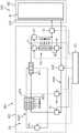
图1示出轨道车辆的示意性侧视图,其例如设计成具有多个用于输送人员的车厢的动车组TZ,其中,仅示出终端车厢EW形式的第一车厢以及中间车厢MW形式的与第一车厢联接的第二车厢。根据可输送人员的期望的数量,动车组具有两个终端车厢以及多个中间车厢,其中,其替选地也可以仅由两个终端车厢构成。此外,轨道车辆可以仅具有唯一一个车厢或者设计为机车。图1中所示的终端车厢EW和中间车厢MW分别具有车厢体WK,车厢体通过两个动轮转向架或从轮转向架形式的转向架DG支撑在未示出的轨道上。相对于这种转向架布局,终端车厢EW的右后端部和中间车厢MW的左前端部也可以支撑在共同的转向架上,尤其所谓的Jakobs转向架上。终端车厢EW相对于纵轴L或水平轴例如划分为多个空间区域。这些区域一方面是前部区域中的驾驶室FS,另一方面是与驾驶室FS邻接的乘客舱FR,其中尤其设置了用于乘客的座椅。中间车厢MW与终端车厢EW不同的是具有仅一个乘客舱FR。车厢EW、MW的乘客舱FR可以由乘客通过布置在相应车厢体WK的侧壁中的未示出的车门进入和离开。此外,乘客可以通过车厢过渡部到达相应的相邻车厢的乘客舱中。这种车厢过渡部通常由波结构或波纹管保护免受环境影响。1 shows a schematic side view of a rail vehicle, which is designed, for example, as an EMU TZ with a plurality of cars for transporting people, wherein only the first car in the form of the terminal car EW and the other cars in the form of the intermediate car MW are shown. The first car is coupled to the second car. Depending on the desired number of people that can be transported, the EMU has two terminal cars and a plurality of intermediate cars, wherein it can alternatively also consist of only two terminal cars. Furthermore, the rail vehicle can have only one car or be designed as a locomotive. The terminal car EW and the intermediate car MW shown in FIG. 1 each have a car body WK, which is supported on rails, not shown, by means of two bogies DG in the form of driving wheel bogies or slave wheel bogies. In contrast to this bogie arrangement, the right rear end of the terminal car EW and the left front end of the intermediate car MW can also be supported on a common bogie, in particular a so-called Jakobs bogie. The terminal car EW is divided, for example, into a plurality of spatial regions with respect to the longitudinal axis L or the horizontal axis. These areas are, on the one hand, the driver's cab FS in the front area and, on the other hand, the passenger compartment FR adjoining the driver's cab FS, in which in particular seats for passengers are provided. The middle car MW differs from the terminal car EW in that it has only one passenger compartment FR. The passenger compartments FR of the cars EW, MW can be entered and left by passengers through not shown doors arranged in the side walls of the respective car bodies WK. Furthermore, passengers can reach the passenger compartments of the respective adjacent cars through the car transitions. Such cabin transitions are usually protected from environmental influences by wave structures or bellows.
在车顶上以及在地板下方或终端车厢EW的车厢体WK的地下区域中布置有用于电气设备的例如多个容器,其作为动车组TZ的电气设施的一部分。它例如用于动车组TZ的驱动或者牵引,尤其用于供应在图1中未专门示出的驱动电机。在端部车厢EW的地下区域中,例如变压器布置在第一容器TRC中,其初级绕组可以通过例如布置在中间车厢MW的车顶上的受电器或受电弓PAN与未示出的导引高压交流电的架空线连接。若轨道车辆只通过导引直流电的架空线或例如第三轨供应电能,则通常不需要变压器。在端部车厢EW的车顶上在另外的容器SRC中例如布置有与变压器相连的牵引换流器,它给驱动电机提供电能。驱动电机例如布置在端部车厢EW的设计为动轮转向架的转向架DG中,其中,在动车组TZ的另外的转向架中,尤其根据需要的最大驱动功率可以布置另外的驱动电机。On the roof and below the floor or in the underground area of the car body WK of the terminal car EW are arranged, for example, containers for electrical equipment as part of the electrical installation of the train TZ. It is used, for example, for the drive or traction of the train TZ, in particular for supplying drive motors that are not specifically shown in FIG. 1 . In the underground area of the end cars EW, for example, a transformer is arranged in the first container TRC, the primary windings of which can be guided through a current collector or pantograph PAN, which is arranged, for example, on the roof of the middle car MW with a not shown guide Overhead line connections for high voltage alternating current. If the rail vehicle is only supplied with electrical energy via overhead lines conducting direct current or, for example, a third rail, a transformer is usually not required. On the roof of the end car EW, in a further container SRC is arranged, for example, a traction converter connected to a transformer, which supplies the drive motor with electrical energy. The drive motor is arranged, for example, in the bogie DG of the end car EW, which is designed as a wheel bogie, wherein further drive motors can be arranged in the further bogies of the train TZ, in particular depending on the maximum drive power required.
在端部车厢EW的车顶上的另外的容器TBC中布置有牵引电池TB形式的储能装置,其例如通过直流电压调节器与牵引换流器的直流电压中间电路相连。相应的容器TBC例如也布置在中间车厢MW的车顶上。将牵引电池分布在轨道车辆的多个车厢上,一方面可以有利地增加牵引电池的总存储量并且以此增加动车组TZ在电池运行下可实现的里程,另一方面可以实现载荷在轨道车辆的车厢或转向架上更有利的分配,例如以便不超过预定的最大车轮载荷。An energy storage device in the form of a traction battery TB is arranged in a further container TBC on the roof of the end car EW, which is connected to the DC voltage intermediate circuit of the traction converter, for example via a DC voltage regulator. A corresponding container TBC is also arranged, for example, on the roof of the middle compartment MW. Distributing the traction batteries on multiple carriages of the rail vehicle can advantageously increase the total storage capacity of the traction batteries on the one hand and thereby increase the achievable mileage of the EMU TZ under battery operation, and on the other hand, can realize the load on the rail vehicle. more favorable distribution on the car or bogie, for example so that a predetermined maximum wheel load is not exceeded.
在车厢EW、MW的车顶上居中例如布置有另外的容器KKC,在其中布置了相对于后续附图进一步说明的相应的冷却和空调装置KKA,冷却和空调装置KKA尤其用于对终端车厢EW和中间车厢MW的相应的乘客舱FR进行空气调节,或者对终端车厢EW的驾驶室FS进行空气调节。For example, a further container KKC is arranged centrally on the roof of the carriages EW, MW, in which a corresponding cooling and air-conditioning unit KKA, which will be described in more detail in relation to the subsequent figures, is arranged, in particular for the purpose of stabilizing the terminal carriage EW. Air conditioning is performed with the corresponding passenger compartment FR of the intermediate compartment MW, or the cab FS of the terminal compartment EW.
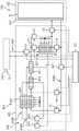
除了动车组TZ的电气设施的所述组件之外,另外的组件,尤其用于控制冷却和空调装置KKA的控制装置STE、另外的辅助运行装置以及用于对它们供电的装置也可以以相同方式布置在车厢的车顶或地下区域中的容器或者甚至其内部空间中。所述组件的所示布局也纯粹是示例。用于变压器的容器TRC例如也可以布置在车厢的车顶上,而牵引电池的容器TBC则可以分别布置在地下区域中。对于动车组的电气设施的另外的组件也相应适用。图2示意性示出按照图1在端部车厢EW的车顶上例如并排布置的容器KKC和TBC连同布置在其中的冷却和空调装置KKA或者储能装置ESA。容器由在此通过相应的点划线限定边界。In addition to the described components of the electrical installation of the train TZ, further components, in particular the control device STE for controlling the cooling and air-conditioning unit KKA, the further auxiliary operating devices and the devices for supplying them can also be used in the same way A container arranged in the roof or underground area of a car or even in its interior space. The illustrated layout of the components is also purely an example. The container TRC for the transformer can also be arranged, for example, on the roof of the carriage, while the container TBC for the traction battery can each be arranged in the underground area. The same applies to further components of the electrical system of the EMU. FIG. 2 schematically shows the containers KKC and TBC arranged side by side on the roof of the end carriage EW according to FIG. 1 , for example, together with the cooling and air conditioning device KKA or the energy storage device ESA arranged therein. The container is delimited here by corresponding dotted lines.
储能装置ESA布置在图2右侧的容器TBC中。其具有至少一个牵引电池TB作为储能器的例子,它例如由多个带有相应的多个相互电连接的蓄电池单池的模块构成。为了在定义的温度段内运行,牵引电池TB与冷却装置KUE相连。冷却装置KUE例如实现为与各个电池单池或模块的壳体相连的由金属、例如铝制成的冷却体,液态的冷却剂通过该冷却体循环。在图2的示意图中,冷却装置KUE仅布置在牵引电池TB的侧面,但在实际应用中,冷却装置KUE优选至少几乎完全覆盖由牵引电池TB或其电池单池或模块占用的基面或者说其顶面、端面或侧面,以保证电池单池的均匀冷却。The energy storage device ESA is arranged in the container TBC on the right side of FIG. 2 . It has at least one traction battery TB as an example of an energy store, which is formed, for example, from a plurality of modules with a corresponding plurality of battery cells that are electrically connected to one another. In order to operate within a defined temperature range, the traction battery TB is connected to the cooling device KUE. The cooling device KUE is implemented, for example, as a cooling body made of metal, eg aluminum, connected to the housing of the individual battery cells or modules, through which cooling body a liquid coolant circulates. In the schematic diagram of FIG. 2 , the cooling device KUE is arranged only on the side of the traction battery TB, but in practical applications the cooling device KUE preferably covers at least almost completely the base area or the base area occupied by the traction battery TB or its battery cells or modules. its top, end or side surfaces to ensure uniform cooling of the battery cells.
根据例如电池单池或模块的可以通过布置在牵引电池TB和/或冷却剂回路KUM中的温度传感器确定的当前温度,图2中额外示意性示出的控制装置STE控制冷却剂向冷却装置KUE的供应,以及必要时控制供应的冷却剂的温度。冷却和空调装置KKA的由控制装置STE控制的组件例如通过作为虚线示出的控制线路与之连接。在图中,控制装置STE显示为布置在用于冷却和空调装置KKA的容器KKC之外。然而它也可以以相同方式与组件一起布置中容器KKC中。同样,控制装置STE可以由多个控制单元构成,它们例如分开但协调地控制制冷装置KAE的组件和冷却剂回路KUM以及空调装置KLE中的可控组件。The control device STE, shown additionally schematically in FIG. 2 , controls the flow of coolant to the cooling device KUE as a function of the current temperature of the battery cells or modules, which can be determined by means of temperature sensors arranged in the traction battery TB and/or in the coolant circuit KUM, for example. supply, and if necessary control the temperature of the supplied coolant. The components of the cooling and air-conditioning unit KKA which are controlled by the control unit STE are connected therewith, for example, via control lines shown as dashed lines. In the figures, the control unit STE is shown arranged outside the container KKC for the cooling and air conditioning unit KKA. However, it can also be arranged in the container KKC together with the assembly in the same way. Likewise, the control device STE can consist of a plurality of control units which, for example, control the components of the refrigeration device KAE and the coolant circuit KUM and the controllable components of the air conditioning device KLE separately but in a coordinated manner.
布置在容器KKC中的冷却和空调装置KKA尤其包括制冷装置KAE。制冷装置KAE的结构和功能例如原则上与压缩制冷机的相应,其按照现有技术尤其已经用于在动车组中乘客舱的空气调节。制冷装置KAE具有第一制冷剂回路KAM1,其中基本上布置有下面说明的四个组件。在已知的压缩制冷机的制冷剂回路中,循环的制冷剂以气态被压缩,由于释放热量而冷凝并通过吸热情况下降压再被蒸发。The cooling and air-conditioning unit KKA arranged in the container KKC includes, in particular, a refrigeration unit KAE. The structure and function of the refrigeration device KAE corresponds, for example, in principle to that of a compression refrigerator, which according to the prior art has been used, in particular, for the air conditioning of passenger compartments in multiple trains. The refrigeration plant KAE has a first refrigerant circuit KAM1 in which basically the four components described below are arranged. In the known refrigerant circuit of a compression refrigerator, the circulating refrigerant is compressed in a gaseous state, condenses due to the release of heat, and is decompressed by endothermic conditions and then evaporated.
反映到制冷剂回路KAM1的在图2中所示的组件上这意味着,制冷剂蒸气被第一压缩机KP1或增压机吸入并通过压缩提高其压力和温度。借助通过控制装置STE启用或停用第一压缩机KP1可以控制第一制冷剂回路KAM1中制冷剂的循环。在沿制冷剂的流动方向连接在第一压缩机KP1后方的第四热交换器WT4中,即冷凝器或液化器中,制冷剂蒸气通过冷却液化。第四热交换器WT4在此设计成空气/制冷剂热交换器,其中制冷剂蒸气例如通过由风机或一个或多个风扇产生的强制冷却空气流被冷却并且由此再被液化。风机或一个或多个风扇由控制装置STE尤其根据期望的体积流量或期望的冷却效果控制。通过在制冷剂的流动方向上连接在第四热交换器WT4后方的没有专门示出的例如设计成膨胀阀的膨胀器降低液态制冷剂的压力和以此降低温度。冷却后的液态制冷剂最后流入第一热交换器WT1,其例如设计成蒸发器,制冷剂在其中蒸发并且由此释放冷能。为了输送处于第一制冷剂回路KAM1中的液态或气态的制冷剂,所述组件通过适当的线路、管道或软管相互连接。Reflected on the components of the refrigerant circuit KAM1 shown in FIG. 2 , this means that the refrigerant vapor is sucked in by the first compressor KP1 or the supercharger and its pressure and temperature are increased by compression. The circulation of the refrigerant in the first refrigerant circuit KAM1 can be controlled by activating or deactivating the first compressor KP1 by means of the control device STE. The refrigerant vapor is liquefied by cooling in a fourth heat exchanger WT4, ie, a condenser or a liquefier, connected in the flow direction of the refrigerant behind the first compressor KP1. The fourth heat exchanger WT4 is designed here as an air/refrigerant heat exchanger, in which the refrigerant vapor is cooled, for example, by a forced cooling air flow generated by a fan or one or more fans and is thereby liquefied again. The fan or one or more fans are controlled by the control device STE, in particular depending on the desired volume flow or the desired cooling effect. The pressure and thus the temperature of the liquid refrigerant are reduced by an expander, not specifically shown, which is connected in the direction of flow of the refrigerant behind the fourth heat exchanger WT4, for example, which is designed as an expansion valve. The cooled liquid refrigerant finally flows into the first heat exchanger WT1, which is designed as an evaporator, for example, in which the refrigerant evaporates and thereby releases cold energy. In order to convey the liquid or gaseous refrigerant in the first refrigerant circuit KAM1, the components are connected to each other by suitable lines, pipes or hoses.
蒸发器设计为空气/制冷剂热交换器,如其按照现有技术在用于乘客舱的空气调节的压缩制冷机中使用的那样。其中,来自乘客舱的暖空气以及必要时额外从车辆的环境输入的新鲜空气借助风机或一个或多个风扇导引通过蒸发器,液态制冷剂在其中蒸发并以此冷却流过的空气。其然后作为空调气流输送给乘客舱。The evaporator is designed as an air/refrigerant heat exchanger, as it is used according to the prior art in compression refrigerators for air conditioning of the passenger compartment. The warm air from the passenger compartment and, if necessary, additionally fresh air supplied from the environment of the vehicle, is conducted by means of a fan or one or more fans through the evaporator, in which the liquid refrigerant evaporates and thereby cools the passing air. This is then delivered to the passenger compartment as an air-conditioned air stream.
第一制冷剂回路KAM1中的第一热交换器WT1与这种已知的蒸发器不同的是,其没有设计成空气/制冷剂热交换器,而是设计成水/制冷剂热交换器。其例如设计成板式热交换器。第一热交换器WT1在此不仅布置在第一制冷剂回路KAM1中,而且还布置在冷却剂回路KUM中,液态冷却剂在冷却剂回路中循环。因此在第一热交换器WT1中处于液态的制冷剂的蒸发由于流过的冷却剂而实现,冷却剂由此又被冷却。冷却和空调装置KKA因此还包括冷却剂回路KUM,其中布置在冷却剂回路KUM中的冷却装置KUE例如布置在容器KKC之外,如图2所示。在第一热交换器WT1中冷却的冷却剂可以输送给储能装置ESA的容器TBC中的冷却装置KUE并且如上所述用于冷却牵引电池TB的电池单池或模块。The first heat exchanger WT1 in the first refrigerant circuit KAM1 differs from this known evaporator in that it is not designed as an air/refrigerant heat exchanger, but as a water/refrigerant heat exchanger. It is designed, for example, as a plate heat exchanger. The first heat exchanger WT1 is here arranged not only in the first refrigerant circuit KAM1 but also in the coolant circuit KUM, in which a liquid coolant circulates. Evaporation of the refrigerant in the liquid state in the first heat exchanger WT1 thus takes place due to the flowing coolant, which is thus cooled again. The cooling and air conditioning unit KKA thus also comprises a coolant circuit KUM, wherein the cooling unit KUE arranged in the coolant circuit KUM is arranged, for example, outside the container KKC, as shown in FIG. 2 . The coolant cooled in the first heat exchanger WT1 can be fed to the cooling device KUE in the container TBC of the energy storage device ESA and used as described above to cool the battery cells or modules of the traction battery TB.
冷却剂的循环例如通过在冷却剂回路KUM中布置并适当设计的冷却剂泵KMP实现。冷却剂泵由控制装置STE控制,由此可以控制其输送功率,其中,控制装置STE也可以仅能打开或关闭冷却剂泵KMP。若有必要,冷却剂回路KUM还具有未示出的补偿容器,补偿容器确保以液态冷却剂和在允许的压力范围内给冷却剂回路永久完全填充。与第一制冷剂回路KAM1相应,布置在冷却剂回路KUM中的组件也通过适当的线路、管道或软管相互连接。The circulation of the coolant takes place, for example, by means of a coolant pump KMP which is arranged in the coolant circuit KUM and is suitably designed. The coolant pump is controlled by the control device STE, whereby its delivery power can be controlled, wherein the control device STE can also only switch the coolant pump KMP on or off. If necessary, the coolant circuit KUM also has a compensation container, not shown, which ensures that the coolant circuit is permanently and completely filled with liquid coolant and within the permissible pressure range. Corresponding to the first refrigerant circuit KAM1, the components arranged in the refrigerant circuit KUM are also interconnected by suitable lines, pipes or hoses.
按照现有技术压缩制冷机中的蒸发器的另外的功能,即借助强制导引通过蒸发器的空气流对动车组TZ的乘客舱FR和/或驾驶室FS进行空气调节,根据本发明由第二热交换器WT2承担。补偿容器设计成一个空气/水热交换器,布置在冷却剂回路KUM中并且在冷却剂的流动方向上连接在第一热交换器WT1后方。借助例如一个或多个由控制装置STE控制的风机,从环境输入的新鲜空气和/或乘客舱的循环空气导引通过第二热交换器WT2并在其中被循环的冷却剂冷却。以此冷却的空气作为空调气流例如通过在车厢内部天花板区域中布置的新鲜空气管道和在内饰板的适当位置处的空气出口供应给乘客舱。According to a further function of the evaporator in the prior art compression refrigerator, namely the air-conditioning of the passenger compartment FR and/or the driver's cab FS of the EMU TZ by means of the air flow forced through the evaporator, according to the invention, the The second heat exchanger WT2 undertakes. The compensation vessel is designed as an air/water heat exchanger, is arranged in the coolant circuit KUM and is connected in the flow direction of the coolant behind the first heat exchanger WT1. The fresh air input from the environment and/or the circulating air of the passenger compartment is conducted through the second heat exchanger WT2 and cooled therein by the circulating coolant, for example by means of one or more fans controlled by the control device STE. The air thus cooled is supplied to the passenger compartment as an air-conditioning air flow, for example via fresh air ducts arranged in the interior ceiling region of the passenger compartment and air outlets at suitable locations in the interior trim panel.
在图2的示例性冷却剂回路KUM中,除了所述的用于循环冷却剂的冷却剂泵KMP、用于通过制冷剂冷却冷却剂的第一热交换器WT1、用于冷却空调气流的第二热交换器WT2和用于冷却牵引电池TB的冷却装置KUE之外,还设置有多个可由控制装置STE控制的阀门V1至V4。它们尤其实现通过控制装置STE灵活地和根据情况控制牵引电池TB以及乘客舱的冷却。In the exemplary coolant circuit KUM of FIG. 2 , in addition to the described coolant pump KMP for circulating the coolant, the first heat exchanger WT1 for cooling the coolant through the refrigerant, the first heat exchanger WT1 for cooling the air-conditioning air flow In addition to the second heat exchanger WT2 and the cooling device KUE for cooling the traction battery TB, a plurality of valves V1 to V4 controllable by the control device STE are provided. In particular, they enable the cooling of the traction battery TB and the passenger compartment to be controlled flexibly and according to the situation via the control device STE.
可控的第一阀门V1布置在第一热交换器WT1和第二热交换器WT2之间或者在冷却剂的流动方向上连接在第二热交换器WT2前方。通过第一阀门V1,冷却剂通过第二热交换器WT2的通流量可以由控制装置STE调节,以便以此影响冷却剂对空调气流的冷却效果。可控的第二阀门V2布置冷却剂回路KUM的平行于第二热交换器WT2和第一阀门V1导引的支路中。根据通过第一阀门V1的通流量,冷却剂的剩余通流量通过该平行的支路或第二阀门V2,即绕过第二热交换器WT2导引。第一阀门V1和第二阀门V2在此也可以由控制装置STE这样控制,使冷却剂只流过第二热交换器WT2或只流过该平行的支路。在第一阀门Vl完全打开和第二阀门V2关闭时因此可以实现对乘客舱的空气调节的最大冷却功率。The controllable first valve V1 is arranged between the first heat exchanger WT1 and the second heat exchanger WT2 or connected in front of the second heat exchanger WT2 in the flow direction of the coolant. Via the first valve V1, the flow rate of the coolant through the second heat exchanger WT2 can be adjusted by the control device STE in order to thereby influence the cooling effect of the coolant on the air-conditioning air flow. The controllable second valve V2 is arranged in a branch of the coolant circuit KUM which runs parallel to the second heat exchanger WT2 and the first valve V1. Depending on the flow through the first valve V1, the remaining flow of the coolant is conducted through this parallel branch or the second valve V2, ie bypassing the second heat exchanger WT2. The first valve V1 and the second valve V2 can also be controlled by the control device STE in such a way that the coolant flows only through the second heat exchanger WT2 or only through this parallel branch. When the first valve V1 is fully open and the second valve V2 is closed, a maximum cooling output for the air conditioning of the passenger compartment can thus be achieved.
可控的第三阀门V3在冷却剂的流动方向上连接在第二热交换器WT2或者说与此平行的支路后方。第三阀门V3平行于可控的第四阀门V4布置,第四阀门在冷却剂的流动方向上连接在冷却装置KUE前方。通过第四阀门V4,控制装置STE根据牵引电池TB的冷却需求调节通过冷却装置KUE的冷却剂的通流量,而剩余量的冷却剂通过第三阀门V3排出或再输送给冷却剂泵KMP。第四阀门V4和第三阀门V3在此也可以由控制装置STE这样控制,使冷却剂只流过冷却装置KUE或只流过第三阀门V3的平行的支路。因此在第四阀门V4完全打开和第三阀门V3关闭时,可以实现牵引电池TB的最大冷却。A controllable third valve V3 is connected downstream of the second heat exchanger WT2 or a branch parallel thereto in the flow direction of the coolant. The third valve V3 is arranged parallel to the controllable fourth valve V4 which is connected upstream of the cooling device KUE in the flow direction of the coolant. Via the fourth valve V4 , the control device STE regulates the flow of coolant through the cooling device KUE according to the cooling demand of the traction battery TB, while the remaining coolant is discharged via the third valve V3 or resupplied to the coolant pump KMP. The fourth valve V4 and the third valve V3 can also be controlled by the control device STE in such a way that the coolant flows only through the cooling device KUE or only through the parallel branch of the third valve V3. Maximum cooling of the traction battery TB can thus be achieved when the fourth valve V4 is fully open and the third valve V3 is closed.
在图2的实施例中,第四阀门V4在冷却剂的流动方向上连接在冷却装置KUE前方。替选地它也可以连接在冷却装置KUE后方。此外还可以设置分别在冷却装置KUE前方和后方的阀门,通过该阀门可以将冷却装置KUE与冷却剂回路KUM完全分离。如果牵引电池TB连同冷却装置KUE例如必须从轨道车辆TZ上移除用于维护或更换,则在将冷却装置KUE必要地从冷却剂回路KUM分离时,有利地不必完全排空冷却剂回路KUM。In the embodiment of FIG. 2 , the fourth valve V4 is connected in front of the cooling device KUE in the flow direction of the coolant. Alternatively, it can also be connected behind the cooling unit KUE. In addition, valves can be provided before and after the cooling unit KUE, by means of which the cooling unit KUE can be completely separated from the coolant circuit KUM. If, for example, the traction battery TB together with the cooling device KUE must be removed from the rail vehicle TZ for maintenance or replacement, the coolant circuit KUM advantageously does not have to be completely drained when the cooling device KUE is necessarily disconnected from the coolant circuit KUM.
图3在上文所述图2的基础上示出根据本发明的冷却和空调装置KKA另外的设计方案。在此,第三热交换器WT3额外布置在冷却剂回路KUM中,第三热交换器在冷却剂的流动方向上连接在第一热交换器WT1前方。第三热交换器WT3示例性地设计为空气/水热交换器,其中通过强制冷却空气流可以冷却循环的冷却剂。第三热交换器WT3为此这样布置,即制冷装置KAE的第四热交换器WT4的强制冷却空气流可以流过第三热交换器。此外,第三热交换器WT3在冷却空气流的方向上连接在第四热交换器WT4前方。然而这种布置不损害第四热交换器WT4的功能,因为第四热交换器中的制冷剂具有大大高于第三热交换器WT3中的冷却剂的温度。相反,两个热交换器在冷却空气流方面的相反布置会导致第三热交换器WT3的冷却功率的严重削弱。原则上,两个热交换器实现为独立的组件,但替选地也可以实现为唯一的组件并且尤其在共同的壳体中。FIG. 3 shows a further configuration of the cooling and air conditioning unit KKA according to the invention on the basis of FIG. 2 described above. Here, a third heat exchanger WT3 is additionally arranged in the coolant circuit KUM, the third heat exchanger being connected upstream of the first heat exchanger WT1 in the flow direction of the coolant. The third heat exchanger WT3 is exemplarily designed as an air/water heat exchanger, in which the circulating coolant can be cooled by a forced cooling air flow. The third heat exchanger WT3 is arranged for this in such a way that the forced cooling air flow of the fourth heat exchanger WT4 of the refrigeration device KAE can flow through the third heat exchanger. Further, the third heat exchanger WT3 is connected in front of the fourth heat exchanger WT4 in the direction of cooling air flow. However, this arrangement does not impair the function of the fourth heat exchanger WT4, since the refrigerant in the fourth heat exchanger has a much higher temperature than the coolant in the third heat exchanger WT3. Conversely, the opposite arrangement of the two heat exchangers in terms of cooling air flow would result in a severe impairment of the cooling power of the third heat exchanger WT3. In principle, the two heat exchangers are implemented as separate components, but can alternatively also be implemented as a single component and in particular in a common housing.
在制冷装置KAE运行时,第三热交换器WT3用于在冷却剂在连接在后方的第一制冷剂回路KAM1的第一热交换器WT1中通过制冷剂进一步冷却之前对其预冷却。然而在制冷装置KAE停用时,冷却剂也可以通过第三热交换器WT3被冷却,其中为此仅须确保提供强制冷却空气流。尤其在环境温度低于舒适温度范围时,其中不必或只需要给乘客舱输送有限的冷却空调气流,则仅在第三热交换器WT3中冷却的冷却剂就可以足够冷却牵引电池TB。When the refrigeration device KAE is in operation, the third heat exchanger WT3 serves to pre-cool the coolant before it is further cooled by the refrigerant in the first heat exchanger WT1 of the first refrigerant circuit KAM1 connected behind. However, the coolant can also be cooled by the third heat exchanger WT3 when the refrigeration device KAE is deactivated, wherein only a forced cooling air flow has to be ensured for this purpose. Especially at ambient temperatures below the comfort temperature range, where no or only limited cooling air-conditioning airflow is required to the passenger compartment, the coolant cooled in the third heat exchanger WT3 alone may be sufficient to cool the traction battery TB.
此外,第五V5和第六可控阀门V6布置在图3的冷却剂回路KUM中。第五阀门V5在此在冷却剂的流动方向上连接在第三热交换器WT3前方,而第六阀门V6布置在冷却剂回路KUM的与第三热交换器WT3和第五阀门V5平行导引的支路中。通过这两个阀门V5、V6,控制装置STE可以调节通过第三热交换器WT3的冷却剂的通流量,以便由此影响第三热交换器WT3对冷却剂的冷却效果。根据通过第五阀门V5的通流量,冷却剂的剩余通流量通过该平行的支路或第六阀门V6,即绕过第三热交换器WT3导引。第五阀门V5和第六阀门V6在此也可以由控制装置STE这样控制,使冷却剂只流过第三热交换器WT3或只流过该平行的支路。在第五阀门V5完全打开和第六阀门V6关闭时,因此可以通过第三热交换器WT3实现对于冷却所述冷却剂的最大的冷却功率,而在第五阀门V5完全关闭和第六阀门V6打开时,冷却剂回路KUM与上文所述图2一致。Furthermore, a fifth V5 and a sixth controllable valve V6 are arranged in the coolant circuit KUM of FIG. 3 . The fifth valve V5 is connected upstream of the third heat exchanger WT3 in the flow direction of the coolant, while the sixth valve V6 is arranged in the coolant circuit KUM and is guided parallel to the third heat exchanger WT3 and the fifth valve V5 in the branch. Via these two valves V5, V6, the control device STE can regulate the flow of coolant through the third heat exchanger WT3 in order to thereby influence the cooling effect of the third heat exchanger WT3 on the coolant. Depending on the flow through the fifth valve V5, the remaining flow of coolant is conducted through this parallel branch or the sixth valve V6, ie bypassing the third heat exchanger WT3. The fifth valve V5 and the sixth valve V6 can also be controlled by the control device STE in such a way that the coolant flows only through the third heat exchanger WT3 or only through this parallel branch. When the fifth valve V5 is fully open and the sixth valve V6 is closed, the maximum cooling power for cooling the coolant can thus be achieved by the third heat exchanger WT3, while the fifth valve V5 is fully closed and the sixth valve V6 is closed. When open, the coolant circuit KUM corresponds to FIG. 2 described above.
图4在上文所述图3的基础上示出根据本发明的冷却和空调装置KKA另外的设计方案。然而,下文所述另外的组件可以以与图2的冷却和空调装置KKA相同的方式实现。FIG. 4 shows a further configuration of the cooling and air-conditioning unit KKA according to the invention on the basis of FIG. 3 described above. However, the further components described below can be implemented in the same way as the cooling and air conditioning unit KKA of FIG. 2 .
冷却和空调装置KKA的空调装置KLE在图4的示例中补充了第五热交换器WT5。第五热交换器设计成空气/水热交换器并这样布置,即空调装置KLE的第二热交换器WT2的强制空调气流可以流过第五热交换器。第五热交换器WT5在此沿空调气流的方向连接在第二热交换器WT2后方。原则上,两个热交换器实现为独立的组件,然而也可以实现为唯一的组件并且尤其在共同的壳体中。The air-conditioning unit KLE of the cooling and air-conditioning unit KKA supplements the fifth heat exchanger WT5 in the example of FIG. 4 . The fifth heat exchanger is designed as an air/water heat exchanger and is arranged such that the forced air-conditioning air flow of the second heat exchanger WT2 of the air conditioning unit KLE can flow through the fifth heat exchanger. The fifth heat exchanger WT5 is connected here behind the second heat exchanger WT2 in the direction of the air-conditioning airflow. In principle, the two heat exchangers are implemented as separate components, but can also be implemented as a single component and in particular in a common housing.
第五热交换器WT5布置在动车组TZ的牵引装置TE的冷却剂回路KMT中。如图4参照图1所示,冷却剂回路KMT源自容器SRC,在该容器中,它用于冷却例如用于牵引装置TE的牵引换流器。替选地的,冷却剂回路KMT也可以源自容器TRC,在该容器中,它用于冷却变压器,或冷却牵引电机。The fifth heat exchanger WT5 is arranged in the coolant circuit KMT of the traction device TE of the EMU TZ. As shown in FIG. 4 with reference to FIG. 1 , the coolant circuit KMT originates from the container SRC, in which it is used to cool the traction inverter for example for the traction device TE. Alternatively, the coolant circuit KMT can also originate from the container TRC, in which it is used to cool the transformer, or to cool the traction motor.
这种牵引装置通常以相较于乘客舱的舒适温度范围明显更高的温度运行,使得它们的冷却剂回路KMT也具有比冷却剂回路KUM的温度更高的温度。第五热交换器WT5因此不用于冷却,而是至少辅助加热输送到乘客舱的空调气流。因为冷却剂回路KMT的温度通常也高于牵引电池TB的定义的温度段,所以第五热交换器WT5如图所示优选地在空调气流的方向上连接在第二热交换器WT后方。尤其若流过第二热交换器WT2的冷却剂的温度高于输送的强制空调气流的温度,则可以在第二热交换器WT2中进行预热并在后方的第五热交换器WT5中进行空调气流的进一步加热。不受此影响地,空调装置KLE可以具有另外的用于加热空调气流的已知器件。由于这些器件通常是用电运行或需供电的,所以这些器件的能耗可以通过有效利用废热有利减少。Such traction devices usually operate at significantly higher temperatures than the comfort temperature range of the passenger compartment, so that their coolant circuit KMT also has a higher temperature than the coolant circuit KUM. The fifth heat exchanger WT5 is therefore not used for cooling, but at least assists in heating the air-conditioning air flow delivered to the passenger compartment. Since the temperature of the coolant circuit KMT is also generally higher than the defined temperature range of the traction battery TB, the fifth heat exchanger WT5 is preferably connected behind the second heat exchanger WT in the direction of the air-conditioning airflow as shown. In particular, if the temperature of the coolant flowing through the second heat exchanger WT2 is higher than the temperature of the delivered forced air-conditioning airflow, preheating can be performed in the second heat exchanger WT2 and performed in the rear fifth heat exchanger WT5 Further heating of the air-conditioning airflow. Independently of this, the air-conditioning unit KLE can have further known means for heating the air-conditioning air flow. Since these devices are typically operated or powered on electricity, the power consumption of these devices can be advantageously reduced by the efficient use of waste heat.
如上文对图2已经说明的,控制装置STE可以通过第一V1和第二阀门V2调节通过第二热交换器WT2的冷却剂的通流量并且以此调节预热的程度。作为补充,在牵引装置TE的冷却剂回路KMT中可以布置可控的第七阀门V7,通过第五热交换器WT5的冷却剂的通流量也可以借助第七阀门通过控制装置STE调节。尤其在冷却空调气流时,控制装置STE完全关闭第七阀门V7,使得没有冷却剂流过第五热交换器WT5和导致空调气流的不期望的加热。As already explained above with respect to FIG. 2 , the control device STE can regulate the flow of coolant through the second heat exchanger WT2 and thereby the degree of preheating via the first V1 and the second valve V2 . In addition, a controllable seventh valve V7 can be arranged in the coolant circuit KMT of the traction device TE, by means of which the flow of coolant through the fifth heat exchanger WT5 can also be adjusted by the control device STE. In particular when cooling the air-conditioning air flow, the control device STE closes the seventh valve V7 completely, so that no coolant flows through the fifth heat exchanger WT5 and causes undesired heating of the air-conditioning air flow.
图5在上文所述图4的设计方案的基础上示出根据本发明的冷却和空调装置KKA另外的设计方案。然而,下文所述另外的组件可以以与图2或者图3的冷却和空调装置KKA相同的方式实现。FIG. 5 shows a further design of the cooling and air-conditioning unit KKA according to the invention on the basis of the design of FIG. 4 described above. However, the further components described below can be implemented in the same way as the cooling and air conditioning unit KKA of FIG. 2 or 3 .
在图5的示例中,冷却和空调装置KKA的制冷装置KAE除了具有第一制冷剂回路KAM1外,还具有第二制冷剂回路KAM2。第二制冷剂回路KAM2或布置在其中的组件与上述就图2所述的第一制冷剂回路KAM1或布置在其中的组件基本相同。原则上,第二制冷剂回路KAM2可以作为纯粹的冗余,以确保在第一制冷剂回路KAM1故障时继续冷却牵引电池和乘客舱的空气调节并且以此确保动车组TZ的运行。在这种情况下,制冷剂回路被这样设计,即两个制冷剂回路分别可以为冷却在冷却剂回路KUM中的冷却剂提供最大的冷却功率。然而根据图5的实施例,第一制冷剂回路KAM1和第二制冷剂回路KAM2的组件这样设计和布置,即只有在两个制冷剂回路KAM1、KAM2并行运行时才提供最大冷却功率,或者两个制冷剂回路KAM1、KAM2中的每一个制冷剂回路只提供制冷装置KAE的最大冷却功率的一部分。有利的是,由此在针对牵引电池TB和/或乘客舱空调的冷却功率需求有限的情况下,例如可以停用制冷剂回路KAM1或KAM2中的一个制冷剂回路,而另一个制冷剂回路在节能范围内运行。在两个制冷剂回路都针对最大冷却功率设计的情况下,在这种情况中启用的制冷剂回路必须在部分负荷范围内运行,在压缩制冷剂设施中这尤其已知是不具能效的。尤其可以以同样的方式使用另外的额外的制冷剂回路,以增加最大冷却功率。In the example of FIG. 5 , the refrigeration unit KAE of the cooling and air conditioning unit KKA has, in addition to the first refrigerant circuit KAM1 , a second refrigerant circuit KAM2 . The second refrigerant circuit KAM2 or the components arranged therein are substantially the same as the first refrigerant circuit KAM1 or the components arranged therein as described above with respect to FIG. 2 . In principle, the second refrigerant circuit KAM2 can serve as a pure redundancy to ensure continued cooling of the traction battery and the air conditioning of the passenger compartment in the event of a failure of the first refrigerant circuit KAM1 and thus ensure the operation of the EMU TZ. In this case, the refrigerant circuits are designed in such a way that the two refrigerant circuits can each provide the maximum cooling power for the refrigerant cooled in the refrigerant circuit KUM. However, according to the embodiment of FIG. 5, the components of the first refrigerant circuit KAM1 and the second refrigerant circuit KAM2 are designed and arranged such that the maximum cooling power is provided only when the two refrigerant circuits KAM1, KAM2 are operated in parallel, or both Each of the refrigerant circuits KAM1, KAM2 only provides a part of the maximum cooling power of the refrigeration unit KAE. Advantageously, it is thus possible, for example, to deactivate one of the refrigerant circuits KAM1 or KAM2, while the other refrigerant circuit is operate within the energy saving range. In the case where both refrigerant circuits are designed for maximum cooling power, the refrigerant circuit activated in this case must operate in the part load range, which is especially known to be energy inefficient in compressed refrigerant installations. In particular, further additional refrigerant circuits can be used in the same way to increase the maximum cooling power.
第六热交换器WT6既布置在第二制冷剂回路KAM2中也布置在冷却剂回路KUM中,第六热交换器与第一制冷剂回路KAM1中的第一热交换器WT1相应设计为水/制冷剂热交换器。因此它就在第二制冷剂回路KAM2中承担蒸发器的功能。第六热交换器WT6根据图5的实施例在冷却剂回路KUM中在冷却剂的流动方向上连接在第一热交换器WT1前方。这意味着,循环的冷却剂首先流过第六热交换器WT6,然后流过第一热交换器WT1,并在这些热交换器中根据制冷剂回路KAM1、KAM2的运行分别被冷却。A sixth heat exchanger WT6 is arranged both in the second refrigerant circuit KAM2 and in the coolant circuit KUM, the sixth heat exchanger being designed corresponding to the first heat exchanger WT1 in the first refrigerant circuit KAM1 as water/ refrigerant heat exchanger. It therefore assumes the function of an evaporator in the second refrigerant circuit KAM2. The sixth heat exchanger WT6 is connected in front of the first heat exchanger WT1 in the coolant circuit KUM in the flow direction of the coolant according to the embodiment of FIG. 5 . This means that the circulating coolant flows first through the sixth heat exchanger WT6 and then through the first heat exchanger WT1 and is cooled in these heat exchangers according to the operation of the refrigerant circuits KAM1, KAM2, respectively.
此外,第七热交换器WT7布置在第二制冷剂回路KAM2中并且与第一制冷剂回路KAM1中的第四热交换器WT4相应设计为空气/制冷剂热交换器。因此它就在第二制冷剂回路KAM2中承担冷凝器或者说液化器的功能。第七热交换器WT7这样布置,即强制的冷却空气流可以流过第七热交换器,其中,第七热交换器在强制的冷却空气流的方向上连接在第四热交换器WT4后方。这意味着强制的冷却空气流首先流过第三热交换器WT3(如果在冷却剂回路KUM中布置有第三热交换器的话),然后流过第四热交换器WT4,最后流过第七热交换器WT7,并在每个热交换器中被进一步加热。原则上,第七热交换器WT7和第四热交换器WT4实现为独立的组件,但替选地也可以实现为唯一的组件并且尤其在共同的壳体中。在此如上所述,尤其第三热交换器WT3也可以实现在该共同的壳体中。Furthermore, the seventh heat exchanger WT7 is arranged in the second refrigerant circuit KAM2 and is designed as an air/refrigerant heat exchanger corresponding to the fourth heat exchanger WT4 in the first refrigerant circuit KAM1. It therefore assumes the function of a condenser or liquefier in the second refrigerant circuit KAM2. The seventh heat exchanger WT7 is arranged such that the forced cooling air flow can flow through the seventh heat exchanger, wherein the seventh heat exchanger is connected behind the fourth heat exchanger WT4 in the direction of the forced cooling air flow. This means that the forced cooling air flow first flows through the third heat exchanger WT3 (if a third heat exchanger is arranged in the coolant circuit KUM), then through the fourth heat exchanger WT4 and finally through the seventh heat exchanger Heat exchanger WT7 and is further heated in each heat exchanger. In principle, the seventh heat exchanger WT7 and the fourth heat exchanger WT4 are realized as separate components, but can alternatively also be realized as a single component and in particular in a common housing. Here, as mentioned above, in particular the third heat exchanger WT3 can also be realized in this common housing.
所述第六热交换器WT6相对于冷却剂回路KUM中的第一热交换器WT1的布局以及第七热交换器WT7相对于冷却空气流中的第四热交换器WT4的布局导致在两个制冷剂回路KAM1、KAM2并行运行时,制冷剂的冷凝和蒸发在其中以分别不同的温度水平进行。第二制冷剂回路KAM2中制冷剂的温度水平在此高于第一制冷剂回路KAM1中制冷剂的温度水平。循环的冷却剂相应地在第六热交换器WT6中通过具有较高温度的制冷剂预冷却,并在后方的第一热交换器WT1中通过具有更低温度的制冷剂进一步冷却。由此减少由于热交换器中制冷剂和冷却剂之间的较高温差产生的有用能损失,并且以此有利提高冷却剂的冷却的效率。The arrangement of the sixth heat exchanger WT6 relative to the first heat exchanger WT1 in the coolant circuit KUM and the arrangement of the seventh heat exchanger WT7 relative to the fourth heat exchanger WT4 in the cooling air flow results in two When the refrigerant circuits KAM1, KAM2 operate in parallel, the condensation and evaporation of the refrigerant take place in them at respectively different temperature levels. The temperature level of the refrigerant in the second refrigerant circuit KAM2 is here higher than the temperature level of the refrigerant in the first refrigerant circuit KAM1. The circulating coolant is accordingly pre-cooled in the sixth heat exchanger WT6 by a refrigerant having a higher temperature, and further cooled by a refrigerant having a lower temperature in the rear first heat exchanger WT1. The loss of useful energy due to the higher temperature difference between the refrigerant and the coolant in the heat exchanger is thereby reduced, and the efficiency of the cooling of the coolant is thereby advantageously increased.
在制冷装置KAE中可以与第一和第二制冷剂回路相对应地设置另外的制冷剂回路。另外的制冷剂回路以同样的方式增加冷却功率,以及替选或者补充地减少有用能损失。Corresponding to the first and second refrigerant circuits, further refrigerant circuits can be provided in the refrigeration device KAE. The additional refrigerant circuit increases the cooling power in the same way, and alternatively or additionally reduces the useful energy losses.
图6示出根据本发明的冷却和空调装置KKA的制冷装置KAE的相对于上文所述图5另外的设计方案的替选方案。该设计方案也基于图4的设计方案,但也可以在图2或图3的冷却和空调装置KKA中实现。FIG. 6 shows an alternative to the further design of the refrigeration unit KAE of the cooling and air-conditioning unit KKA according to the invention with respect to FIG. 5 described above. This design is also based on the design of FIG. 4 , but can also be implemented in the cooling and air conditioning unit KKA of FIG. 2 or 3 .
图6中的第二制冷剂回路KAM2与图5中的上文所述的第二制冷剂回路的不同在于第六热交换器WT6和第七热交换器WT7分别相对于第一制冷剂回路KAM1的第一热交换器WT1和第四热交换器WT4的布局。在此,第六热交换器WT6布置在与第一热交换器WT1平行的冷却剂回路KUM中,第七热交换器WT7布置在与第四热交换器WT4平行的冷却空气流中。The second refrigerant circuit KAM2 in FIG. 6 differs from the above-described second refrigerant circuit in FIG. 5 in that the sixth heat exchanger WT6 and the seventh heat exchanger WT7 are respectively relative to the first refrigerant circuit KAM1 The layout of the first heat exchanger WT1 and the fourth heat exchanger WT4. Here, the sixth heat exchanger WT6 is arranged in the coolant circuit KUM parallel to the first heat exchanger WT1, and the seventh heat exchanger WT7 is arranged in the cooling air flow parallel to the fourth heat exchanger WT4.
通过热交换器WT6和WT1或WT7和WT4的相应平行的布局,两个制冷剂回路KAM1、KAM2在并行运行时具有相同的制冷剂温度水平。在第一热交换器WT1和第六热交换器WT6前方但在第三热交换器WT3和可控的第六阀门V6后方(若这些都分别布置在冷却剂回路KUM中),冷却剂回路KUM在冷却剂的流动方向上被分开。相应地,循环的冷却剂基本上以相同的部分既流过第一热交换器WT1也流过第六热交换器WT6,在这两个热交换器中冷却剂分别通过第一制冷剂回路KAM1或者第二制冷剂回路KAM2中的制冷剂冷却。Due to the corresponding parallel arrangement of the heat exchangers WT6 and WT1 or WT7 and WT4, the two refrigerant circuits KAM1, KAM2 have the same refrigerant temperature level when operating in parallel. In front of the first heat exchanger WT1 and the sixth heat exchanger WT6 but behind the third heat exchanger WT3 and the controllable sixth valve V6 (if these are respectively arranged in the coolant circuit KUM), the coolant circuit KUM are divided in the direction of flow of the coolant. Accordingly, the circulating coolant flows in substantially the same portion both through the first heat exchanger WT1 and through the sixth heat exchanger WT6, in which the coolant passes through the first refrigerant circuit KAM1, respectively Or the refrigerant in the second refrigerant circuit KAM2 is cooled.
在图6的示例中,在冷却剂的流动方向上在第六热交换器WT6前方,额外连接有可控的第八阀门V8。这种可由控制装置STE控制的阀门可以替选地连接在第六热交换器WT6后方。通过第八阀门V8,控制装置STE可以调节通过第六热交换器WT6的冷却剂的通流量,其中,也可以通过完全关闭第八阀门V8完全抑制冷却剂的流动。后者尤其在第二制冷剂回路KAM2故障时有意义。以同样的方式,在冷却剂回路KUM中平行布置的第一热交换器WT1前方或者后方可以连接可控的阀门,以便相应通过控制装置STE调节冷却剂通过第一热交换器WT1的流动。In the example of FIG. 6 , in front of the sixth heat exchanger WT6 in the flow direction of the coolant, a controllable eighth valve V8 is additionally connected. Such a valve controllable by the control device STE can alternatively be connected behind the sixth heat exchanger WT6. Via the eighth valve V8, the control device STE can regulate the flow of coolant through the sixth heat exchanger WT6, wherein the flow of coolant can also be completely suppressed by completely closing the eighth valve V8. The latter is particularly relevant in the event of a failure of the second refrigerant circuit KAM2. In the same way, a controllable valve can be connected upstream or downstream of the first heat exchanger WT1 arranged in parallel in the coolant circuit KUM in order to accordingly regulate the flow of coolant through the first heat exchanger WT1 by means of the control device STE.
如上文就图5和图6所述,使用具有两个或更多制冷剂回路的制冷设备KAE有利地实现循环的冷却剂的更有效和更精细的调节冷却。根据相应的制冷剂回路的运行和可控阀门V5、V6和V8的位置,循环的冷却剂可以在第三热交换器WT3中通过强制冷却空气流冷却和/或在第一热交换器WT1中通过第一制冷剂回路KAM1中的制冷剂冷却和/或在第六热交换器WT6中通过第二制冷剂回路KAM2中的制冷剂冷却。根据牵引电池以及用于乘客舱空气调节的空调气流的相应的冷却需求,由控制装置STE由此可以实现冷却和空调装置KKA不同组件尤其在能耗方面最佳的运行。高能效的冷却和空气调节在主要或唯一的能源是牵引电池的轨道车辆中特别重要,因为包括冷却和空调装置的辅助运行装置或辅助机组的低效运行会导致用储存在牵引电池中的电能所能实现的里程减少或者需要增加牵引电池的容量。As described above with respect to Figures 5 and 6, the use of a refrigeration plant KAE with two or more refrigerant circuits advantageously enables more efficient and finer regulated cooling of the circulating coolant. Depending on the operation of the respective refrigerant circuits and the positions of the controllable valves V5, V6 and V8, the circulating coolant may be cooled by a forced cooling air flow in the third heat exchanger WT3 and/or in the first heat exchanger WT1 Cooled by the refrigerant in the first refrigerant circuit KAM1 and/or in the sixth heat exchanger WT6 by the refrigerant in the second refrigerant circuit KAM2. Depending on the corresponding cooling requirements of the traction battery and the air-conditioning air flow for the air conditioning of the passenger compartment, the control device STE can thereby achieve optimal operation of the various components of the cooling and air-conditioning device KKA, in particular with regard to energy consumption. Energy efficient cooling and air conditioning is particularly important in rail vehicles where the primary or only energy source is traction batteries, because inefficient operation of auxiliary operating units or auxiliary units including cooling and air conditioning units can lead to use of electrical energy stored in traction batteries The achievable range is reduced or the capacity of the traction battery needs to be increased.
Claims (15)
Applications Claiming Priority (3)
| Application Number | Priority Date | Filing Date | Title |
|---|---|---|---|
| DE102019220400.7 | 2019-12-20 | ||
| DE102019220400.7ADE102019220400B4 (en) | 2019-12-20 | 2019-12-20 | Rail vehicle with a cooling and air conditioning arrangement |
| PCT/EP2020/084220WO2021121991A1 (en) | 2019-12-20 | 2020-12-02 | Rail vehicle having a cooling and air conditioning assembly |
Publications (1)
| Publication Number | Publication Date |
|---|---|
| CN114929547Atrue CN114929547A (en) | 2022-08-19 |
Family
ID=73834462
Family Applications (1)
| Application Number | Title | Priority Date | Filing Date |
|---|---|---|---|
| CN202080092453.5APendingCN114929547A (en) | 2019-12-20 | 2020-12-02 | Rail vehicle with cooling and air conditioning device |
Country Status (5)
| Country | Link |
|---|---|
| EP (1) | EP4054887B1 (en) |
| CN (1) | CN114929547A (en) |
| DE (1) | DE102019220400B4 (en) |
| ES (1) | ES3023543T3 (en) |
| WO (1) | WO2021121991A1 (en) |
Families Citing this family (2)
| Publication number | Priority date | Publication date | Assignee | Title |
|---|---|---|---|---|
| DE102021201795A1 (en) | 2021-02-25 | 2022-08-25 | Siemens Mobility GmbH | Cooling device for a vehicle battery |
| EP4600107A1 (en)* | 2024-02-07 | 2025-08-13 | Siemens Mobility GmbH | Temperature control system |
Citations (5)
| Publication number | Priority date | Publication date | Assignee | Title |
|---|---|---|---|---|
| CN102686423A (en)* | 2009-12-21 | 2012-09-19 | 韦巴斯托股份公司 | Motor vehicle cooling system |
| DE102016121362A1 (en)* | 2016-11-08 | 2018-05-09 | Hanon Systems | Device for distributing heat in a motor vehicle and method for operating the device |
| CN109383227A (en)* | 2017-08-13 | 2019-02-26 | 康唯特公司 | Circuit system for fuel-cell vehicle |
| CN109895590A (en)* | 2017-12-08 | 2019-06-18 | 现代自动车株式会社 | The HVAC system of vehicle |
| DE102017223214A1 (en)* | 2017-12-19 | 2019-06-19 | Siemens Aktiengesellschaft | Track-bound vehicle, arrangement for cooling an energy storage device of the track-bound vehicle and method for controlling the arrangement |
Family Cites Families (9)
| Publication number | Priority date | Publication date | Assignee | Title |
|---|---|---|---|---|
| DE19545450C2 (en) | 1995-12-06 | 2000-06-29 | Abb Patent Gmbh | Device for air conditioning a vehicle interior of an electrically operated vehicle |
| DE19609048C2 (en) | 1996-03-08 | 1998-04-16 | Daimler Benz Ag | Heating and air conditioning device for motor vehicles |
| DE19937949C2 (en) | 1998-06-02 | 2003-01-16 | Webasto Thermosysteme Gmbh | Device and method for heating and / or cooling a vehicle interior |
| FR2830927B1 (en) | 2001-10-12 | 2004-04-02 | Peugeot Citroen Automobiles Sa | IMPROVED THERMAL REGULATION DEVICE FOR A MOTOR VEHICLE, PARTICULARLY OF THE ELECTRIC OR HYBRID TYPE |
| US7451808B2 (en) | 2004-09-17 | 2008-11-18 | Behr Gmbh & Co. | Exchanging device for motor vehicles |
| AT512634B1 (en) | 2012-03-01 | 2014-06-15 | Vossloh Kiepe Ges M B H | Air conditioning for cooling, heating and ventilating railway wagons |
| DE102017201186A1 (en) | 2017-01-25 | 2018-07-26 | Siemens Aktiengesellschaft | Vehicle with a two-stage refrigeration system |
| DE102018117097A1 (en)* | 2018-07-16 | 2020-01-16 | Hanon Systems | Heat exchanger arrangement for an air conditioning system and air conditioning system of a motor vehicle, and method for operating the air conditioning system |
| DE102018219859B4 (en)* | 2018-11-20 | 2020-09-03 | Audi Ag | Refrigeration system for a vehicle and vehicle with a refrigeration system |
- 2019
- 2019-12-20DEDE102019220400.7Apatent/DE102019220400B4/enactiveActive
- 2020
- 2020-12-02WOPCT/EP2020/084220patent/WO2021121991A1/ennot_activeCeased
- 2020-12-02EPEP20824130.7Apatent/EP4054887B1/enactiveActive
- 2020-12-02ESES20824130Tpatent/ES3023543T3/enactiveActive
- 2020-12-02CNCN202080092453.5Apatent/CN114929547A/enactivePending
Patent Citations (5)
| Publication number | Priority date | Publication date | Assignee | Title |
|---|---|---|---|---|
| CN102686423A (en)* | 2009-12-21 | 2012-09-19 | 韦巴斯托股份公司 | Motor vehicle cooling system |
| DE102016121362A1 (en)* | 2016-11-08 | 2018-05-09 | Hanon Systems | Device for distributing heat in a motor vehicle and method for operating the device |
| CN109383227A (en)* | 2017-08-13 | 2019-02-26 | 康唯特公司 | Circuit system for fuel-cell vehicle |
| CN109895590A (en)* | 2017-12-08 | 2019-06-18 | 现代自动车株式会社 | The HVAC system of vehicle |
| DE102017223214A1 (en)* | 2017-12-19 | 2019-06-19 | Siemens Aktiengesellschaft | Track-bound vehicle, arrangement for cooling an energy storage device of the track-bound vehicle and method for controlling the arrangement |
Also Published As
| Publication number | Publication date |
|---|---|
| DE102019220400A1 (en) | 2021-06-24 |
| WO2021121991A1 (en) | 2021-06-24 |
| ES3023543T3 (en) | 2025-06-02 |
| EP4054887B1 (en) | 2025-01-29 |
| DE102019220400B4 (en) | 2022-08-04 |
| EP4054887C0 (en) | 2025-01-29 |
| EP4054887A1 (en) | 2022-09-14 |
Similar Documents
| Publication | Publication Date | Title |
|---|---|---|
| US11904911B2 (en) | Track-guided vehicle, arrangement for cooling an energy storage device of the track-guided vehicle, and method for controlling the arrangement | |
| KR101971062B1 (en) | Air conditioning system for an automobile | |
| ES2348456T3 (en) | SYSTEM AND FEEDING PROCEDURE FOR A RAILWAY VEHICLE, A CONVERTER, A PILOT UNIT, AND AIR CONDITIONER FOR THIS SYSTEM. | |
| CN102848876A (en) | Device for thermally conditioning a vehicle drivetrain and a vehicle cabin | |
| CN114929547A (en) | Rail vehicle with cooling and air conditioning device | |
| EP3859848B1 (en) | Rail vehicle with cooling device for a fuel cell assembly | |
| AU2005234878A1 (en) | Heating and air-conditioning system for a motor vehicle | |
| EP3560789B1 (en) | Railway vehicle and method of controlling the same | |
| PL207128B1 (en) | Power supply means for rail vehicle | |
| US11760213B2 (en) | Railway vehicle equipped with an electrical storage body | |
| CN112670615B (en) | Device for controlling the temperature of an energy storage device | |
| CN219325823U (en) | Rail vehicle air conditioning system and rail vehicle | |
| US12011969B2 (en) | Vehicle air conditioning system | |
| WO2005052459A3 (en) | Air conditioning assembly | |
| RU72446U1 (en) | AIR CONDITIONING SYSTEM IN PASSENGER RAILWAY CAR | |
| RU111084U1 (en) | AIR CONDITIONING SYSTEM IN A PASSENGER WAGON OF A HIGH-SPEED RAILWAY VEHICLE | |
| RU2512068C2 (en) | Passenger car modular air conditioning system | |
| RU108560U1 (en) | MODULAR AIR CONDITIONING SYSTEM FOR PASSENGER CAR | |
| US1978854A (en) | Air cooling system | |
| KR20030095122A (en) | Air cooling and heating system for railway vehicle |
Legal Events
| Date | Code | Title | Description |
|---|---|---|---|
| PB01 | Publication | ||
| PB01 | Publication | ||
| SE01 | Entry into force of request for substantive examination | ||
| SE01 | Entry into force of request for substantive examination |