CN114929123A - Devices and systems for facilitating insertion of a bone treatment device - Google Patents
Devices and systems for facilitating insertion of a bone treatment deviceDownload PDFInfo
- Publication number
- CN114929123A CN114929123ACN202080091868.0ACN202080091868ACN114929123ACN 114929123 ACN114929123 ACN 114929123ACN 202080091868 ACN202080091868 ACN 202080091868ACN 114929123 ACN114929123 ACN 114929123A
- Authority
- CN
- China
- Prior art keywords
- sleeve
- lumen
- outer sleeve
- guidewire
- bone
- Prior art date
- Legal status (The legal status is an assumption and is not a legal conclusion. Google has not performed a legal analysis and makes no representation as to the accuracy of the status listed.)
- Pending
Links
Images


Classifications
- A—HUMAN NECESSITIES
- A61—MEDICAL OR VETERINARY SCIENCE; HYGIENE
- A61B—DIAGNOSIS; SURGERY; IDENTIFICATION
- A61B17/00—Surgical instruments, devices or methods
- A61B17/56—Surgical instruments or methods for treatment of bones or joints; Devices specially adapted therefor
- A61B17/58—Surgical instruments or methods for treatment of bones or joints; Devices specially adapted therefor for osteosynthesis, e.g. bone plates, screws or setting implements
- A61B17/88—Osteosynthesis instruments; Methods or means for implanting or extracting internal or external fixation devices
- A61B17/90—Guides therefor
- A—HUMAN NECESSITIES
- A61—MEDICAL OR VETERINARY SCIENCE; HYGIENE
- A61B—DIAGNOSIS; SURGERY; IDENTIFICATION
- A61B17/00—Surgical instruments, devices or methods
- A61B17/16—Instruments for performing osteoclasis; Drills or chisels for bones; Trepans
- A61B17/1613—Component parts
- A61B17/1633—Sleeves, i.e. non-rotating parts surrounding the bit shaft, e.g. the sleeve forming a single unit with the bit shaft
- A—HUMAN NECESSITIES
- A61—MEDICAL OR VETERINARY SCIENCE; HYGIENE
- A61B—DIAGNOSIS; SURGERY; IDENTIFICATION
- A61B17/00—Surgical instruments, devices or methods
- A61B17/16—Instruments for performing osteoclasis; Drills or chisels for bones; Trepans
- A61B17/17—Guides or aligning means for drills, mills, pins or wires
- A61B17/1717—Guides or aligning means for drills, mills, pins or wires for applying intramedullary nails or pins
- A—HUMAN NECESSITIES
- A61—MEDICAL OR VETERINARY SCIENCE; HYGIENE
- A61B—DIAGNOSIS; SURGERY; IDENTIFICATION
- A61B17/00—Surgical instruments, devices or methods
- A61B17/16—Instruments for performing osteoclasis; Drills or chisels for bones; Trepans
- A61B17/17—Guides or aligning means for drills, mills, pins or wires
- A61B17/1739—Guides or aligning means for drills, mills, pins or wires specially adapted for particular parts of the body
- A61B17/1764—Guides or aligning means for drills, mills, pins or wires specially adapted for particular parts of the body for the knee
- A—HUMAN NECESSITIES
- A61—MEDICAL OR VETERINARY SCIENCE; HYGIENE
- A61B—DIAGNOSIS; SURGERY; IDENTIFICATION
- A61B17/00—Surgical instruments, devices or methods
- A61B17/56—Surgical instruments or methods for treatment of bones or joints; Devices specially adapted therefor
- A61B17/58—Surgical instruments or methods for treatment of bones or joints; Devices specially adapted therefor for osteosynthesis, e.g. bone plates, screws or setting implements
- A61B17/88—Osteosynthesis instruments; Methods or means for implanting or extracting internal or external fixation devices
- A61B17/8872—Instruments for putting said fixation devices against or away from the bone
- A—HUMAN NECESSITIES
- A61—MEDICAL OR VETERINARY SCIENCE; HYGIENE
- A61B—DIAGNOSIS; SURGERY; IDENTIFICATION
- A61B17/00—Surgical instruments, devices or methods
- A61B17/56—Surgical instruments or methods for treatment of bones or joints; Devices specially adapted therefor
- A61B17/58—Surgical instruments or methods for treatment of bones or joints; Devices specially adapted therefor for osteosynthesis, e.g. bone plates, screws or setting implements
- A61B17/88—Osteosynthesis instruments; Methods or means for implanting or extracting internal or external fixation devices
- A61B17/8897—Guide wires or guide pins
- A—HUMAN NECESSITIES
- A61—MEDICAL OR VETERINARY SCIENCE; HYGIENE
- A61B—DIAGNOSIS; SURGERY; IDENTIFICATION
- A61B17/00—Surgical instruments, devices or methods
- A61B17/56—Surgical instruments or methods for treatment of bones or joints; Devices specially adapted therefor
- A61B17/58—Surgical instruments or methods for treatment of bones or joints; Devices specially adapted therefor for osteosynthesis, e.g. bone plates, screws or setting implements
- A61B17/88—Osteosynthesis instruments; Methods or means for implanting or extracting internal or external fixation devices
- A61B17/92—Impactors or extractors, e.g. for removing intramedullary devices
- A61B17/921—Impactors or extractors, e.g. for removing intramedullary devices for intramedullary devices
- A—HUMAN NECESSITIES
- A61—MEDICAL OR VETERINARY SCIENCE; HYGIENE
- A61B—DIAGNOSIS; SURGERY; IDENTIFICATION
- A61B17/00—Surgical instruments, devices or methods
- A61B17/56—Surgical instruments or methods for treatment of bones or joints; Devices specially adapted therefor
- A61B17/58—Surgical instruments or methods for treatment of bones or joints; Devices specially adapted therefor for osteosynthesis, e.g. bone plates, screws or setting implements
- A61B17/88—Osteosynthesis instruments; Methods or means for implanting or extracting internal or external fixation devices
- A61B17/8802—Equipment for handling bone cement or other fluid fillers
- A61B17/8805—Equipment for handling bone cement or other fluid fillers for introducing fluid filler into bone or extracting it
- A61B17/8816—Equipment for handling bone cement or other fluid fillers for introducing fluid filler into bone or extracting it characterised by the conduit, e.g. tube, along which fluid flows into the body or by conduit connections
- A—HUMAN NECESSITIES
- A61—MEDICAL OR VETERINARY SCIENCE; HYGIENE
- A61B—DIAGNOSIS; SURGERY; IDENTIFICATION
- A61B17/00—Surgical instruments, devices or methods
- A61B2017/00831—Material properties
- A61B2017/00862—Material properties elastic or resilient
- A—HUMAN NECESSITIES
- A61—MEDICAL OR VETERINARY SCIENCE; HYGIENE
- A61B—DIAGNOSIS; SURGERY; IDENTIFICATION
- A61B17/00—Surgical instruments, devices or methods
- A61B17/02—Surgical instruments, devices or methods for holding wounds open, e.g. retractors; Tractors
- A61B17/025—Joint distractors
- A61B2017/0268—Joint distractors for the knee
Landscapes
- Health & Medical Sciences (AREA)
- Surgery (AREA)
- Life Sciences & Earth Sciences (AREA)
- Orthopedic Medicine & Surgery (AREA)
- Biomedical Technology (AREA)
- Nuclear Medicine, Radiotherapy & Molecular Imaging (AREA)
- Engineering & Computer Science (AREA)
- Heart & Thoracic Surgery (AREA)
- Medical Informatics (AREA)
- Molecular Biology (AREA)
- Animal Behavior & Ethology (AREA)
- General Health & Medical Sciences (AREA)
- Public Health (AREA)
- Veterinary Medicine (AREA)
- Oral & Maxillofacial Surgery (AREA)
- Dentistry (AREA)
- Surgical Instruments (AREA)
Abstract
Translated fromChinese
Description
Translated fromChinese技术领域technical field
本公开整体涉及一种促进将骨治疗装置插入到活体中的装置和系统,并且具体地涉及用于促进将髓内钉插入到骨(例如,胫骨)中的装置和系统。The present disclosure relates generally to a device and system for facilitating insertion of a bone treatment device into a living body, and in particular to a device and system for facilitating insertion of an intramedullary nail into a bone (eg, a tibia).
背景技术Background technique
用于将髓内(IM)钉插入到胫骨中的规程可利用髌上方法执行。虽然这种技术通常促进胫骨的近侧和远侧的骨折的治疗,但在进行用于IM钉的进入路径的钻孔和扩孔期间以及在钉本身的插入期间,可对膝关节施加升高的压力。The procedure for inserting an intramedullary (IM) nail into the tibia can be performed using a suprapatellar approach. While this technique generally facilitates the treatment of proximal and distal fractures of the tibia, elevation can be applied to the knee joint during drilling and reaming for the entry path of the IM nail and during insertion of the nail itself pressure.
发明内容SUMMARY OF THE INVENTION
本公开涉及一种用于促进将骨治疗装置插入到活体中的装置,该装置包括柔性材料的外套筒,该柔性材料的外套筒形成纵向延伸穿过该外套筒的外导管,用于将骨治疗装置插入到身体内的目标部位。外导管的远侧开口是打开的,使得当外套筒处于身体内的期望位置时,穿过外导管插入的骨治疗装置邻近骨的目标部分离开外套筒。The present disclosure relates to a device for facilitating insertion of a bone treatment device into a living body, the device comprising an outer sleeve of flexible material forming an outer conduit extending longitudinally through the outer sleeve, using It is used to insert bone treatment devices into the target site in the body. The distal opening of the outer catheter is open so that a bone treatment device inserted through the outer catheter exits the outer sleeve adjacent the target portion of the bone when the outer sleeve is in the desired position within the body.
该装置还包括内套筒,该内套筒被接纳在外套筒内并且限定外导管内的内导管。该内套筒在外导管内形成护盖。该内套筒由金属形成。该内套筒沿纵向分裂。该内套筒在裂口的相对侧上的部分彼此联接,使得内导管的直径可响应于由骨治疗装置和外套筒周围的组织中的一者施加在内导管上的力而在预先确定的范围内调节。The device also includes an inner sleeve received within the outer sleeve and defining an inner conduit within the outer conduit. The inner sleeve forms a cover within the outer conduit. The inner sleeve is formed of metal. The inner sleeve is split longitudinally. Portions of the inner sleeve on opposite sides of the split are coupled to each other such that the diameter of the inner catheter is responsive to a force exerted on the inner catheter by one of the bone treatment device and the tissue surrounding the outer sleeve at a predetermined adjustment within the range.
本发明的实施方案还涉及一种治疗骨的系统,该系统包括被构造用于插入活体内的插入装置,该插入装置向身体内的目标部位提供导管。该插入装置包括柔性材料的外套筒,该柔性材料的外套筒形成纵向延伸穿过该外套筒的外管腔。外管腔的远侧开口是打开的,使得当外套筒处于身体内的期望位置时,穿过外管腔插入的骨治疗装置邻近骨的目标部分离开外套筒,并且内套筒被接纳在外套筒内并且限定外管腔内的内管腔。该内套筒在外管腔内形成护盖。该内套筒由金属形成。该内套筒沿纵向分裂。该内套筒在裂口的相对侧上的部分彼此联接,使得内管腔的直径可响应于由穿过导管插入的物品和外套筒周围的组织中的一者施加在内管腔上的力而在预先确定的范围内调节。Embodiments of the present invention also relate to a system for treating bone comprising an insertion device configured for insertion into a living body, the insertion device providing a catheter to a target site within the body. The insertion device includes an outer sleeve of flexible material forming an outer lumen extending longitudinally through the outer sleeve. The distal opening of the outer lumen is open such that when the outer sleeve is in a desired position within the body, a bone treatment device inserted through the outer lumen exits the outer sleeve adjacent the target portion of the bone and the inner sleeve is received Within the outer sleeve and defining an inner lumen within the outer lumen. The inner sleeve forms a cover within the outer lumen. The inner sleeve is formed of metal. The inner sleeve is split longitudinally. Portions of the inner sleeve on opposite sides of the split are coupled to each other such that the diameter of the inner lumen is responsive to forces exerted on the inner lumen by one of an item inserted through the catheter and the tissue surrounding the outer sleeve And adjust within a predetermined range.
该系统还包括导线器,该导线器的尺寸和形状被设定用于穿过导管插入到目标部位。该导线器包括沿导线器的中心纵向轴线延伸的第一管腔。该第一管腔的尺寸和形状被设定成可滑动地接纳穿过该第一管腔的导丝。该导线器包括与第一管腔侧向偏置并且平行于第一管腔的第二管腔。该第二管腔的尺寸和形状被设定成可滑动地接纳穿过该第二管腔的导丝。The system also includes a guide sized and shaped for insertion through the catheter to the target site. The guide includes a first lumen extending along a central longitudinal axis of the guide. The first lumen is sized and shaped to slidably receive a guidewire therethrough. The guide includes a second lumen laterally offset from and parallel to the first lumen. The second lumen is sized and shaped to slidably receive a guidewire therethrough.
附图说明Description of drawings
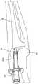
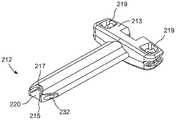
图1示出了根据一个实施方案的设备的透视图,该设备位于与支腿相邻并且在支腿内的位置;Figure 1 shows a perspective view of a device in a position adjacent to and within a leg, according to one embodiment;
图2示出了图1的设备的分解图;Figure 2 shows an exploded view of the apparatus of Figure 1;
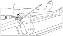
图3示出了膝关节的解剖结构和图1的设备连同已经插入到胫骨中的导丝的视图;Figure 3 shows the anatomy of the knee joint and a view of the device of Figure 1 with a guide wire that has been inserted into the tibia;
图4示出了与图1的设备一起使用的导线器的近侧端部的视图;Figure 4 shows a view of a proximal end of a wire guide for use with the device of Figure 1;
图5示出了根据另一实施方案的导线器的透视图,该导线器包括直径增大的部分和直径减小的部分;5 shows a perspective view of a thread guide including an enlarged diameter portion and a reduced diameter portion according to another embodiment;
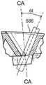
图6示出了与钻头结合使用的图1的组件的透视图;Figure 6 shows a perspective view of the assembly of Figure 1 used in conjunction with a drill bit;
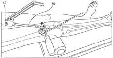
图7示出了结合图1的设备插入到胫骨中的IM钉的透视图;Figure 7 shows a perspective view of an IM nail inserted into the tibia in conjunction with the device of Figure 1;
图8示出了根据另一实施方案的保护组件的透视图;Figure 8 shows a perspective view of a protection assembly according to another embodiment;
图9示出了图8的组件的局部剖视图;Figure 9 shows a partial cross-sectional view of the assembly of Figure 8;
图10示出了图8的组件的芯保护套筒的视图;Figure 10 shows a view of the core protection sleeve of the assembly of Figure 8;
图11示出了可以形成图10的芯保护套筒的材料片的透视图;Figure 11 shows a perspective view of a sheet of material from which the core protection sleeve of Figure 10 may be formed;
图12示出了图11的片材和图10的芯保护套筒的端视图;Figure 12 shows an end view of the sheet of Figure 11 and the core protection sleeve of Figure 10;
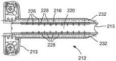
图13示出了根据又一个实施方案的保护组件的透视图;Figure 13 shows a perspective view of a protection assembly according to yet another embodiment;
图14示出了图13的保护组件的端视图;Figure 14 shows an end view of the protection assembly of Figure 13;
图15示出了图13的保护组件的剖视图;Figure 15 shows a cross-sectional view of the protection assembly of Figure 13;
图16示出了图13的组件的实施方案的内部保护套筒;Figure 16 shows the inner protective sleeve of the embodiment of the assembly of Figure 13;
图17示出了可以形成图16的芯保护套筒的材料片的透视图;Figure 17 shows a perspective view of a sheet of material from which the core protection sleeve of Figure 16 may be formed;
图18示出了图13的组件的另一实施方案的内部保护套筒;Figure 18 shows the inner protective sleeve of another embodiment of the assembly of Figure 13;
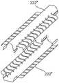
图19示出了可以形成图18的芯保护套筒的材料片的透视图;Figure 19 shows a perspective view of a sheet of material from which the core protection sleeve of Figure 18 may be formed;
图20示出了图19的两个片材,这两个片材被定位成将接合来形成图18的芯保护套筒;Figure 20 shows the two sheets of Figure 19 positioned to be joined to form the core protection sleeve of Figure 18;
图21示出了根据另一实施方案的内部保护套筒的侧视图;Figure 21 shows a side view of an inner protective sleeve according to another embodiment;
图22示出了图21的内部保护套筒的剖视图;Figure 22 shows a cross-sectional view of the inner protective sleeve of Figure 21;
图23示出了被接纳在外套筒内的图21的内部保护套筒的剖视图;Figure 23 shows a cross-sectional view of the inner protective sleeve of Figure 21 received within the outer sleeve;
图24示出了根据另一实施方案的保护组件的透视图;Figure 24 shows a perspective view of a protection assembly according to another embodiment;
图25示出了根据一个实施方案的套管针的侧视图;Figure 25 shows a side view of a trocar according to one embodiment;
图26示出了根据另一实施方案的导线器的透视图;Figure 26 shows a perspective view of a thread guide according to another embodiment;
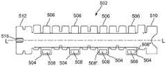
图27示出了可形成图30至图32的芯保护套筒的材料片的侧视图;Figure 27 shows a side view of a sheet of material from which the core protection sleeve of Figures 30-32 may be formed;
图28A示出了弯曲成用于形成图30至图32的芯保护套筒的初步形状的图27的片材的前视图;Figure 28A shows a front view of the sheet of Figure 27 bent into a preliminary shape for forming the core protection sleeve of Figures 30-32;
图28B示出了弯曲成用于形成图30至图32的芯保护套筒的初步形状的图27的片材的侧视图;Figure 28B shows a side view of the sheet of Figure 27 bent into a preliminary shape for forming the core protection sleeve of Figures 30-32;
图29示出了弯曲成用于形成图30至图32的芯保护套筒的初步形状的图27的片材的底视图;Figure 29 shows a bottom view of the sheet of Figure 27 bent into a preliminary shape for forming the core protection sleeve of Figures 30-32;
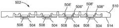
图30示出了由如图27所示的片材形成的芯保护套筒的侧视图;Figure 30 shows a side view of a core protection sleeve formed from the sheet material shown in Figure 27;
图31示出了由如图27所示的片材形成的芯保护套筒的前视图;Figure 31 shows a front view of a core protection sleeve formed from the sheet material shown in Figure 27;
图32示出了由如图27所示的片材形成的芯保护套筒的透视图;Figure 32 shows a perspective view of a core protection sleeve formed from the sheet material shown in Figure 27;
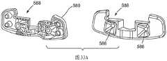
图33A示出了根据一个实施方案的保护组件的柄部的透视图,其中柄部的两半彼此分开;33A shows a perspective view of a handle of a protection assembly with the two halves of the handle separated from each other, according to one embodiment;
图33B示出了图33A的柄部的一半的顶视图;Figure 33B shows a top view of one half of the handle of Figure 33A;
图34示出了图33A的柄部的导丝开口的剖视图;Figure 34 shows a cross-sectional view of the guide wire opening of the handle of Figure 33A;
图35示出了与图33A的柄部一起使用的锁定环的侧视图;Figure 35 shows a side view of the locking ring used with the handle of Figure 33A;
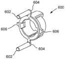
图36示出了图35的锁定环的透视图;Figure 36 shows a perspective view of the locking ring of Figure 35;
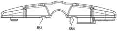
图37示出了与包括图33A的柄部和图35的锁定环的保护组件的实施方案一起使用的外套筒;Figure 37 shows an outer sleeve for use with an embodiment of a protection assembly including the handle of Figure 33A and the locking ring of Figure 35;
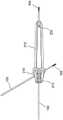
图38示出了根据一个实施方案的固定导丝的透视图;Figure 38 shows a perspective view of a fixation guidewire according to one embodiment;
图39示出了带有图38的固定导丝的图13的保护组件的顶视图;并且Fig. 39 shows a top view of the protective assembly of Fig. 13 with the fixed guide wire of Fig. 38; and
图40示出了带有图38的固定导丝的图13的保护组件的侧视图。40 shows a side view of the protection assembly of FIG. 13 with the fixed guidewire of FIG. 38. FIG.
具体实施方式Detailed ways
参照以下描述和附图可进一步理解本发明,其中相同的参考标号指代类似的元件。示例性实施方案描述了用于胫骨IM钉的髌上插入的装置和规程。如本文所用,术语远侧和近侧是指远离支腿与身体的附接点(远侧)和朝向支腿与身体的附接点(近侧)的方向。尽管本文所述的实施方案具体被构造用于胫骨IM钉的髌上插入的规程,但本领域技术人员将理解,本文所述的实施方案也可以用于涉及脊外科手术的规程。The present invention can be further understood by reference to the following description and drawings, wherein like reference numerals refer to like elements. Exemplary embodiments describe devices and procedures for suprapatellar insertion of tibial IM nails. As used herein, the terms distal and proximal refer to directions away from the point of attachment of the leg to the body (distal) and towards the point of attachment of the leg to the body (proximal). Although the embodiments described herein are specifically configured for use in procedures for suprapatellar insertion of tibial IM nails, those skilled in the art will understand that the embodiments described herein may also be used in procedures involving spinal surgery.
如本领域技术人员将理解的,胫骨骨折可以通过插入IM钉来治疗,并且在某些情况下,IM钉利用髌上方法插入。在这些情况下,经由膝盖骨和股骨之间的空间将器械诸如钻具和扩孔器以及IM钉本身插入到胫骨的近侧端部中。这种方法需要置换膝盖骨,并且可能对膝盖骨、其支撑解剖结构和周围组织施加压力。一般来讲,保护套筒穿过该空间被插入以保护周围组织免受损伤,否则该器械或钉本身接触周围组织可能会导致损伤。该空间周围的组织被移位,并且在保护套筒保持在该位置的整个时间期间经受很大的应力。本发明实施方案提供了对周围组织的保护,同时减小了在规程期间施加在该组织上的应力。一般来讲,此类规程涉及(使用任何已知的技术)减少骨折,此后还使用任何已知的技术来确定IM钉的长度和直径。此后,形成切口并且确定IM钉的进入部位。此外,可以采用技术诸如钝性解剖来松开膝盖骨并且允许其从股骨移开。As those skilled in the art will appreciate, tibial fractures can be treated by insertion of IM nails, and in some cases, IM nails are inserted using a suprapatellar approach. In these cases, instruments such as drills and reamers and the IM nails themselves are inserted into the proximal end of the tibia via the space between the kneecap and the femur. This approach requires replacement of the kneecap and may place pressure on the kneecap, its supporting anatomy, and surrounding tissue. Generally, a protective sleeve is inserted through the space to protect the surrounding tissue from damage that might otherwise result from contact of the instrument or the staple itself with the surrounding tissue. The tissue surrounding this space is displaced and is subject to significant stress during the entire time the protective sleeve remains in this position. Embodiments of the present invention provide protection of surrounding tissue while reducing the stress placed on the tissue during the procedure. Generally, such procedures involve reducing fractures (using any known technique) and thereafter also determining the length and diameter of the IM nail using any known technique. Thereafter, an incision is made and the entry site of the IM staple is determined. Additionally, techniques such as blunt dissection can be employed to loosen the kneecap and allow it to move away from the femur.
如图1和图2所示,可以采用下文关于图13详细描述的保护套筒组件212。套管针22然后穿过保护套筒组件212被插入,并且该组合被插入到进入部位,以便IM钉经由切口进入身体,并且穿过膝关节,例如在膝盖骨24的关节表面和远侧股骨26之间到达胫骨28的近侧端部。然后通过将导丝放置到胫骨或股骨中的任一者而将保护套筒组件212固定就位,这将在下面更详细地描述。As shown in FIGS. 1 and 2, a
如图38至图40所示,可以使用固定导丝100执行胫骨固定。固定导丝100从近侧端部103延伸到远侧端部105,并且包括例如焊接到固定导丝100的肩部或止挡件102,以及在远侧端部105处的螺纹尖端104。止挡件102的尺寸和形状被设定成防止固定导丝100进入保护套筒组件212超出期望的深度。止挡件102被定位成使得当固定导丝100根据需要被插入到胫骨中时,止挡件102和保护组件套筒212之间的接触将保护套筒组件212抵靠胫骨保持在期望位置。As shown in FIGS. 38-40 , tibial fixation may be performed using a
如下所述,保护套筒组件212包括由金属诸如不锈钢形成的内套筒和由易变形材料诸如柔性塑料形成的外套筒。因此,内部金属套筒保护外部塑料套筒免受在钻孔、扩孔等过程中可能发生的对较软塑性材料的损坏。插入设备,直到套管针22到达进入部位B处的胫骨28的表面,例如近侧胫骨的前表面。As described below, the
此时,套管针22被移除,并且如图3和图4所示,导线器30穿过保护套筒组件212被插入,以引导第一导丝32沿将被钻出用于将IM钉插入到胫骨28的髓管中的期望的路径被放置穿过进入部位。本领域技术人员将理解,导丝32可根据需要使用任何已知技术被插入。在这种情况下,导丝32经由导线器30放置到胫骨28中,该导线器穿过保护套筒组件212被插入到进入部位。导丝32穿过沿导线器30的纵向轴线(在该实施方案中,与保护套筒组件212的中心轴线重合)延伸的中心管腔34,以沿平行于导线器30的中心管腔34的路径并且由该导线器的该中心管腔的路径限定的路径进入胫骨28。然后可以使用导线器30如下所述检查和调节导丝32的定位。At this point, the
在检查了导丝32的位置之后,如果确定导丝32的位置应该被调节,则外科医生通过在导丝32上方抽回导线器30直到导丝32离开该导线器,然后将导丝32重新插入到与中心管腔34径向偏置并且平行于该中心管腔的偏置管腔36中来移除导线器30。然后,导线器30越过导丝32穿过保护套筒组件212到胫骨的近侧表面,并且根据需要旋转,直到中心管腔34与期望的路径对准,沿该期望的路径期望将第二导丝32插入到胫骨28中。然后根据需要放置第二导丝32并且移除第一导丝32。此外,如图5所示,根据另一实施方案的导线器30'的外径沿其长度变化,以允许在导线器30'被接纳穿过保护套筒组件212时该保护套筒组件部分地径向塌缩。具体地,导线器30'的外径包括远侧部分31和近侧部分31',该远侧部分的外径基本上对应于保护套筒组件212在其远侧端部处的内径,当导线器30'被完全插入时,该远侧端部接触胫骨,并且该近侧部分在导线器30'被完全插入时被接纳在保护套筒组件212的由中心的直径减小部分33分开的近侧端部中。After checking the position of the
这确保导线器30'在保护套筒组件212中正确居中,同时允许保护套筒组件212的中间部分径向地部分塌缩,从而减小施加到周围组织的压力,这将在下面更详细地描述。如图6所示,钻头38然后在导丝32(第二导丝)上方推进,并且被推进穿过保护套筒组件212到进入部位,在该进入部位,外科医生钻出通往髓管的进入孔,如本领域技术人员将理解的。此后,外科医生移除钻头,并且如果需要,可在导丝32上方推进扩孔器(或扩孔杆,即2.5mm至3mm长的柔性钢杆),以对钻出的开口和/或髓管进行扩孔,如本领域技术人员将理解的。This ensures that the guide 30' is properly centered within the
如图7所示,一旦已经准备好进入路径和髓管,就可以移除扩孔器并且准备好IM钉40用于插入。如本领域技术人员将理解的,IM钉40的近侧端部可以联接到插入柄部42,并且IM钉40的远侧端部穿过保护套筒组件212被插入到进入路径。在完成进入路径/髓管的准备和IM钉40准备好插入之间的时间期间,保护套筒组件212部分地径向向内塌缩,从而允许周围组织放松一些,进而减少与其移位相关联的创伤。这同样减少了髌上空间的组织经受高水平应力的时间。然后可以使用任何已知的技术将IM钉40插入到胫骨28中并且锁定就位。As shown in Figure 7, once the access pathway and medullary canal have been prepared, the reamer can be removed and the
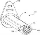
如图8至图12所示,用于经由例如髌上方法插入IM钉40的保护套筒组件112的另一实施方案可与单独的柄部一起使用。具体地,套筒112包括从近侧端部基部115延伸的外部软保护套筒114,该近侧端部基部以已知的方式联接到柄部。外套筒114围绕金属内芯套筒116,该金属内芯套筒保护外套筒114不被插入穿过组件112的钻具扩孔器等损坏。芯套筒116包括径向凸缘118,这些径向凸缘与外套筒114的对应结构配合,以将芯套筒116保持在外套筒114内的期望位置。As shown in FIGS. 8-12, another embodiment of a
此外,径向凸缘118使芯套筒116的近侧端部和远侧端部基本上不可压缩,从而通过确保芯套筒116的远侧端部的直径保持足够接纳物品,使得更容易将已经朝远侧插入超出组件112的物品拉回到组件112中。芯套筒116被构造成允许芯套筒116在其管腔120未被不可压缩物品(例如,IM钉、钻具、扩孔器等)占据时在经受压缩力(例如,由周围组织施加的力)时径向向内偏转。Additionally, the
如图11和图12所示,该实施方案的芯套筒116可由金属片材121形成。片材可由任何合适的材料,诸如围绕纵向轴线L缠绕以形成圆柱体并且在弯曲轴线B上方弯曲以形成径向凸缘118的任何硬化弹簧钢形成。片材121包括一系列纵向空隙124,该一系列纵向空隙增强了芯套筒116的柔性,使得当没有器械穿过套筒组件112时(或者当被接纳在组件112内的物品的外径小于芯套筒116的内径时),组件112径向向内塌缩以减少对组件112周围的组织的损伤。此外,该实施方案的外套筒114包括在管腔120的相对侧上延伸的2个导丝管腔126。尽管在该实施方案中导丝管腔126平行于管腔120延伸,但导丝管腔126可以沿相对于管腔120的不同方向延伸。如本领域技术人员将理解的,导丝管腔126可用于通过将导丝穿过导丝管腔插入到胫骨的近侧端部中而将组件112固定在胫骨上的期望位置。在另一个实施方案中,芯套筒116可由任何合适材料的管形成,该管具有类似于纵向空隙124的纵向空隙。As shown in FIGS. 11 and 12 , the
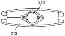
图13至图15示出了根据又一实施方案的保护套筒组件212,该保护套筒组件从其近侧端部处的柄部213延伸到远侧端部215,该远侧端部的形状被设定成基本上平坦地贴靠骨的目标部分。外套筒214围绕金属内芯套筒216,该金属内芯套筒保护外套筒214不被插入穿过组件212的钻具扩孔器等损坏。远侧端部215优选地被制成比装置的其余部分更具刚性,使得它保持完全打开,并且远侧端部215包括斜面217,以促进通过确保组件212的远侧端部的直径保持足够接纳物品而将已经朝远侧插入超出组件212的物品(例如,扩孔器)拉回到组件212中。芯套筒216被构造成允许芯套筒216在其管腔220未被不可压缩物品(例如,IM钉、钻具、扩孔器等)占据时在经受压缩力(例如,由周围组织施加的力)时径向向内偏转。Figures 13-15 illustrate a
如图13所示,柄部213还包括两个导丝插入开口219,这两个导丝插入开口被构造成允许将导丝插入到股骨中以将组件212固定到股骨,如果需要,作为将组件212固定到胫骨的替代方案或作为补充。开口219形成为基本上锥形的开口,以允许导丝相对于柄部213在允许的角度范围内以任何期望的取向成角度。例如,开口219可允许引导件以任何角度插入顶角为55度的锥体内。As shown in FIG. 13, the
如图16至图20所示,该实施方案的芯套筒216可由金属或类似于上文关于芯套筒116所述的其他材料的一个或多个片材222形成。如图16和图17所示,芯套筒216'通过围绕纵向轴线L=缠绕单个片材222'形成,以形成大致卵形结构,该大致卵形结构在其相对侧上具有纵向开口224。然后可以焊接缠绕的片材222'的端部以形成卵形管状结构。As shown in FIGS. 16-20 , the
如图17所示,片材222在其外边缘上包括一系列横向狭缝226。在芯套筒216'的相对侧上形成为狭槽的纵向开口224通过将在狭缝226中的相邻狭缝之间形成的翅片228径向向外弯曲而形成。如图15所示,芯套筒216'的所得结构装配到外套筒214的相应地设定形状的内部空间中。在另一个实施方案中,纵向开口224可沿任何曲线例如螺旋曲线成形。在另一个实施方案中,芯套筒216可由与上文关于芯套筒116所述的材料相同的材料形成的管形成,该管具有类似于纵向空隙224的纵向开口和类似于横向狭缝226的横向狭缝。As shown in Figure 17, the
片材222'还包括纵向狭缝228,其中一系列横向狭缝230以规则的间隔与狭缝228相交。芯套筒216被成形和构造成增强组件212沿横向于轴线L的方向,特别是沿跨狭槽224的宽度的方向的可压缩性。组件212被构造成沿周围组织施加最大压缩力的方向具有最大可偏转性。即,对于该装置,组件212被设计成更容易沿前后方向压缩,因为这是由周围组织施加到组件212的最大力的方向。Sheet 222' also includes
如本领域技术人员将理解的,纵向开口224的宽度(开口224沿横向于组件212的纵向轴线的方向的范围)限定了芯套筒216的最大偏转,并且因此限定了组件212的最大偏转。即,当偏转到最大量时,纵向开口224的相对的两侧将彼此接触。如上所述,当没有器械穿过套筒组件212时(或者当被接纳在组件212内的物品的外径小于芯套筒216的内径时),组件212径向向内塌缩以减少对组件212周围的组织的损伤。此外,该实施方案的外套筒214包括平行于管腔220并且在该管腔的相对侧上延伸的2个导丝管腔232。As will be understood by those skilled in the art, the width of the longitudinal opening 224 (the extent of the
如图18至图20所示,内芯保护套筒216"可由两个片材222"形成,每个片材被压成基本上对称的形状并且在片材的边缘处焊接在一起。与套筒216'不同,套筒216"不包括侧向狭槽224。相反,片材222"的翅片226'弯曲成侧向延伸离开套筒216"的中心轴线L@,使得它们作为一组在套筒216"的任一侧上形成翼部225。类似于开口224,翼225的宽度限定了芯套筒216"的最大偏转,并且因此限定了该芯套筒安装在其中的组件的最大偏转。即,当偏转到最大量时,翼225的相对的两侧彼此接触。As shown in Figures 18-20, the core
图21至图23示出了用于包括在本文所述的任何保护套筒组件中的芯保护套筒312。套筒312被构造成插入到本申请中所述的任何外套筒中,以形成耐用的保护套筒组件,该耐用的保护套筒组件将在钻孔和扩孔等过程中抵抗损坏。在该实施方案中,芯保护套筒312包括具有第一直径的近侧部分314和具有大于第一直径的第二直径的远侧部分316。直径增大的远侧部分316的尺寸被设定成使套筒312在保护套筒组件的远侧端部处居中,以正确瞄准扩孔器或钻头320的操作头318,而直径减小的近侧部分314的尺寸被设定成接纳扩孔器或钻头320的带有允许保护套筒组件部分塌缩的空隙的驱动轴322。21-23 illustrate a
如本领域技术人员将理解的,近侧部分314和远侧部分316的内径的尺寸分别被设定成允许与容纳在其中的扩孔器或钻头320的部分有足够大的空隙,使得扩孔器或钻头320可在芯保护套筒312内自由旋转。因此,保护套筒312的仅容纳芯保护套筒312的远侧部分316的一部分被防止径向塌缩而减小组织应力。因此,当使用芯保护套筒312时,保护套筒312的大部分长度自由地压缩和减小周围组织上的应力。如图23所示,近侧部分316的外径之间的空隙从远侧部分314的近侧端部延伸到保护套筒312的近侧端部,从而允许保护套筒312沿该整个部分局部径向塌缩。应当理解,芯保护套筒312可以仅与具有直径减小的轴的装置一起使用,该直径减小的轴沿装置长度的大部分延伸。As will be understood by those skilled in the art, the inner diameters of the
如图24所示,根据另一实施方案的保护套筒组件412基本上类似于上述保护套筒组件212,不同之处在于组件412不包括任何导丝管腔,并由此提供减小的轮廓,进一步减小对周围组织的损伤。即,保护套筒组件412可以由不希望将导丝插入到胫骨中来将组件412固定在期望位置的用户选择。在这种情况下,组件412将仅经由穿过柄部413中的导丝开口419插入的导丝来固定。如图24所示,保护套筒组件412从其近侧端部处的柄部413延伸到远侧端部415,该远侧端部的形状被设定成基本上平坦地贴靠骨的目标部分。As shown in FIG. 24, a
外套筒414围绕金属内芯套筒416,该金属内芯套筒保护外套筒414不被插入穿过组件412的钻具扩孔器等损坏。芯套筒416可根据本文所述的任何实施方案构造。远侧端部415优选地被制成比装置的其余部分更具刚性,使得它保持完全打开,并且远侧端部415包括斜面417,以促进通过确保组件412的远侧端部的直径保持足够接纳物品而将已经朝远侧插入超出组件412的物品(例如,扩孔器)拉回到组件412中。The
如上所述,芯套筒416被构造成允许芯套筒416在其管腔未被不可压缩物品(例如,IM钉、钻具、扩孔器等)占据时在经受压缩力(例如,由周围组织施加的力)时径向向内偏转。柄部413还包括两个导丝插入开口419,这两个导丝插入开口被构造成允许将导丝插入到股骨中以将组件412固定到股骨。开口419形成为基本上锥形的开口,以允许导丝相对于柄部413在允许的角度范围内以任何期望的取向成角度。As described above, the
图25示出了与本文所述的任何保护套筒组件一起使用的套管针430。套管针430包括钝的锥形远侧尖端432。套管针430的尺寸被设定成使得当在其近侧端部处的柄部434安置在保护套筒组件的柄部的相应地设定尺寸和形状的凹槽中时(例如,在组件412的柄部413的凹槽420内),远侧端部432从套筒414朝远侧突出以提供钝的分离尖端,从而促进组合的套管针430和组件412在导丝上方插入到与胫骨的近侧端部相邻的目标侧。Figure 25 shows a
套管针430包括直径减小的近侧轴436,该直径减小的近侧轴的直径小于远侧尖端432的直径。该实施方案的远侧尖端432和近侧部分438的直径基本上对应于芯套筒416的内径,以使套管针430在组件412内居中。套管针430还包括可选的锁定结构440,所述可选的锁定结构被构造成与凹槽420中的对应结构卡扣接合,以将套管针430保持在组件412内的期望位置。如本领域技术人员将理解的,导线器诸如导线器30可用于在插入期间加强保护组件,并且提供锥形尖端,以在将保护套筒组件插入到与胫骨的近侧端部相邻的期望位置时促进钝性解剖。The
如图26所示,根据另选的实施方案的导线器450包括沿导线器450的纵向轴线延伸的中心管腔452(在该实施方案中,与其中插入该导线器的保护套筒412的中心轴线重合)。如上所述,如果确定需要调节导丝的位置,则外科医生通过在导丝上方抽回导线器450直到导丝离开该导线器,然后将导丝重新插入到与中心管腔452径向偏置并且平行于该中心管腔的偏置管腔454中来移除导线器450。然后,导线器450越过导丝穿过保护套筒412到达胫骨的近侧表面,并且根据需要旋转,直到中心管腔452与期望的路径对准,沿该期望的路径期望将第二导丝插入到胫骨中。然后根据需要经由中心管腔452将第二导丝放置到胫骨中,并且移除第一导丝。如图26所示,导线器450的远侧部分456形成为带有刮削的平坦面458的圆柱体的一部分。As shown in FIG. 26, a
在另选的实施方案中,导线器450通过切口直接插入到胫骨。导线器通过导线器450以类似于上述方式的方式插入到胫骨中,并且保护套筒412在不使用套管针的情况下直接插入到导线器上方。然后将保护套筒412固定到胫骨、股骨或这两者上。在固定保护套筒412之后,移除导线器450。在这样的实施方案中,导线器450被制造成尽可能细,即,导线器450的远侧部分具有减小的直径,带有钝的尖端和变平的侧面。In an alternative embodiment, the
该实施方案的远侧部分456的尺寸被设定成尽可能小,同时容纳中心管腔452和偏置管腔454。这允许穿过其中插入的保护套筒组件部分塌缩,从而进一步减少对周围组织的损伤。如本领域技术人员将理解的,导线器450的长度被选择为使得当导线器450被完全插入到保护套筒组件中时,导线器450的远侧端部460接触胫骨,而近侧端部462朝近侧延伸出其已经被插入穿过的保护套筒组件的柄部。如图26所示,导线器450的远侧端部460形成为圆形凹入端以促进组织的钝性解剖,使得该导线器450可另选地用于替代套管针430,以促进保护套筒组件在导丝上方插入到胫骨的近侧端部处的目标部位。The
如图27至图32所示,可用于本文所述的任何保护套筒组件内的另一实施方案的芯套筒500可由金属或类似于上文关于芯套筒116所述的其他材料的两个片材502形成。如图27至图32所示,根据该实施方案的芯套筒500通过围绕纵向轴线L弯曲一对片材502来形成,使得每个片材502形成大致管状结构的一半,两个半部彼此成镜像。每个片材502包括多个接纳突片504,每个接纳突片沿第一侧表面限定突片接纳开口508,在相对的侧表面上沿轴线L在对应的位置处形成有对应的多个锁定突片506。As shown in FIGS. 27-32 , the
片材502中的第一片材的锁定突片506中的每一个锁定突片的尺寸和位置被设定成在片材502已经弯曲成它们的半管状形状之后被接纳穿过另一个片材502的相应地定位的接纳突片504的突片接纳开口508。如图28A、图28B和图29所示,在该实施方案的片材502已经弯曲成它们的大致半管状形状之后,接纳突片504大致沿由片材502形成的管的切线延伸,而锁定突片506远离轴线L径向向外突出。因此,当片材502被组装来形成芯套筒500的大致管状结构时,每个锁定突片506径向向外突出穿过其对应的接纳突片504的突片接纳开口508。Each of the locking
在随后的操作中,如图30至图32所示,然后将每个锁定突片506朝某个位置弯曲,在该位置中,锁定突片506的外端朝该锁定突片与片材502的连接点向后延伸,该锁定突片从该片材基本上平行于该锁定突片延伸穿过的接纳突片504延伸。这将两个片材502锁定在一起,同时允许由片材502形成的芯套筒的管状结构以与上述关于其他芯套筒的相同的方式在来自周围组织的压力下收缩。该收缩C的范围由突片接纳开口508沿管状结构切线方向的尺寸减去突片506的厚度(即,由突片506中的每一者在其对应的突片接纳开口508内允许的运动范围)来限定。In subsequent operations, as shown in FIGS. 30-32 , each locking
此外,两个套筒502经由例如在它们的远侧端部510处焊接而彼此联接,而片材502的近侧端部512不彼此焊接。具体地,该实施方案的远侧端部510沿接缝514激光焊接。本领域技术人员将理解,这将允许根据该实施方案的芯套筒的管状结构在IM钉的弯曲部分被迫穿过该芯套筒时在该芯套筒的近侧端部512处更容易展开。Furthermore, the two
此外,锁定突片506和接纳突片504之间的连接增强了根据该实施方案的芯套筒对剪切力的抵抗,当弯曲的IM钉被推动穿过保护套筒时,保护套筒经受来自膝盖骨-股骨关节的剪切力。即,当弯曲的IM钉被推动穿过保护套筒时,芯套筒的(例如,沿IM钉中的弯曲部的内径的)一半可被推动以在保护套筒内朝近侧迁移,而芯套筒的另一半经历沿相反方向将其推动的力。这建立了作用在两个片材502之间的剪切力,在该实施方案中,通过锁定突片506分别与突片接纳开口508的近侧端部远侧表面508'、508"之间的接触来抵抗这些剪切力,防止在IM钉穿过该片材被插入时片材502相对于彼此的迁移。In addition, the connection between the locking
此外,锁定突片506分别与突片接纳开口508的近侧端部远侧表面508'、508"之间的连接防止在钉弯曲穿过时芯套筒的径向向外展开,从而将膝关节上的压力最小化。此外,片材502中的每一个片材包括突片516,如下所述,该突片用于将芯套筒锁定到柄部,以防止芯套筒在IM钉被朝远侧推动穿过该芯套筒时在保护套筒内朝远侧迁移。In addition, the connection between the locking
如图33至图37所示,例如与芯套筒500一起使用的保护套筒组件550包括外套筒560、柄部580,将外套筒560、芯套筒500和柄部580彼此联接的锁定环600。如图33所示,柄部580由彼此联接的两个半部形成,以接纳在套筒560的近侧端部564处侧向向外突出的粘结平台562。粘结平台562被接纳在形成于柄部580的两半之间的相应地设定尺寸和形状的腔体582内。此外,在芯套筒500已经被插入到外套筒560中之后,将锁定环600安置在近侧开口564内,其中锁定环600的安装柱602在开口564的任一侧被接纳在凹腔566内,直到柱602中的每一者的远侧面604搁置在凹腔566的远侧端部处的面向近侧的表面上。As shown in Figures 33-37, for example, a protective sleeve assembly 550 for use with a
当锁定环600朝远侧插入到开口564中时,锁定环的侧向突出的突起606滑入芯套筒500中,直到突起606中的每一者进入芯套筒500的突片516中的对应的一个突片下方的开口中,以将芯套筒500锁定在外套筒560内的期望位置处。在该实施方案中,外套筒560不包括用于胫骨固定的侧向导丝管腔。因此,在该实施方案中,柱602朝近侧伸出外套筒560以接合柄部580中的开口584,在包括此类胫骨固定导丝管腔的实施方案中,这些开口将穿过柄部580以通向这些导丝管腔。如本领域技术人员将理解的,该实施方案的外套筒560可基本类似于上述的任何外套筒,不同之处在于近侧端部处的用于将外套筒560固定到柄部580的结构。When the
该实施方案的锁定环600不仅将芯套筒500锁定在外套筒560内的期望位置处,而且还用于塞住柄部580中的胫骨固定导丝开口。本领域技术人员将理解,对于包括用于胫骨固定的侧向导丝的外套筒,锁定环将被构造成类似于锁定环600,不同之处在于将不包括柱602,使得导丝开口584不受阻碍。应当理解,此类外套筒的导丝管腔将被定位成使得穿过柄部580中的开口584中的任一个开口插入的导丝将穿过柄部580进入侧向导丝管腔中的一者的近侧开口中,并且以与上述方式相同的方式穿过该导丝管腔到达胫骨的近侧表面。The
当柄部580的两半彼此联接时,卡扣在粘结平台562上方以将外套筒560锁定到柄部580。如图33A和图34所示,柄部580包括两个导丝开口586,其目的是允许将导丝插入到股骨中以稳定保护套筒组件500。如图34所示,导丝开口586中的每一个导丝开口形成为顶角为55度的锥体的一部分(即,导丝可以从开口586的中心轴线CA沿任何方向以高达27.5度的角度穿过开口586中的任一个开口插入。然而,本领域技术人员将理解,该角度α可以是允许所要求的股骨固定的任何期望的值。如上所述,在柄部580的近侧端部处的凹槽588的尺寸、形状和结构被设定成接纳如上所述的套管针或将穿过组件550的中心管腔被插入的任何其他装置并且将其锁定就位。When the two halves of the
尽管已经结合胫骨IM钉的髌上插入描述了这些实施方案,但本领域技术人员将理解,该系统也可用于脊外科手术。此外,尽管已经描述了特定的实施方案和方法,但应当理解,在不脱离如所附权利要求中限定的本发明的精神或范围的情况下,可以采取不同于上述讨论的各种修改。例如,等同的元件可以替代那些具体示出和描述的元件,某些特征部可以独立于其他特征部使用,并且在某些情况下,元件的特定应用可以颠倒或插入,所有这些都不脱离本发明的精神或范围。Although these embodiments have been described in connection with suprapatellar insertion of tibial IM nails, those skilled in the art will understand that the system may also be used in spinal surgery. Furthermore, while specific embodiments and methods have been described, it should be understood that various modifications other than those discussed above may be employed without departing from the spirit or scope of the invention as defined in the appended claims. For example, equivalent elements may be substituted for those specifically shown and described, certain features may be used independently of others, and in some cases the particular application of elements may be reversed or inserted, all without departing from this the spirit or scope of the invention.
Claims (18)
Translated fromChineseApplications Claiming Priority (3)
| Application Number | Priority Date | Filing Date | Title |
|---|---|---|---|
| US16/674,406US11490942B2 (en) | 2019-11-05 | 2019-11-05 | Device and system for facilitating insertion of a bone treatment device |
| US16/674406 | 2019-11-05 | ||
| PCT/IB2020/060377WO2021090210A1 (en) | 2019-11-05 | 2020-11-04 | Device and system for facilitating insertion of a bone treatment device |
Publications (1)
| Publication Number | Publication Date |
|---|---|
| CN114929123Atrue CN114929123A (en) | 2022-08-19 |
Family
ID=73401862
Family Applications (1)
| Application Number | Title | Priority Date | Filing Date |
|---|---|---|---|
| CN202080091868.0APendingCN114929123A (en) | 2019-11-05 | 2020-11-04 | Devices and systems for facilitating insertion of a bone treatment device |
Country Status (8)
| Country | Link |
|---|---|
| US (1) | US11490942B2 (en) |
| EP (1) | EP4054442B1 (en) |
| JP (1) | JP7631333B2 (en) |
| CN (1) | CN114929123A (en) |
| AU (1) | AU2020378712A1 (en) |
| BR (1) | BR112022008527A2 (en) |
| CA (1) | CA3159925A1 (en) |
| WO (1) | WO2021090210A1 (en) |
Families Citing this family (3)
| Publication number | Priority date | Publication date | Assignee | Title |
|---|---|---|---|---|
| US11918235B1 (en)* | 2020-09-03 | 2024-03-05 | Smith & Nephew, Inc. | Tissue protection sleeve |
| CN114053541B (en)* | 2021-11-11 | 2022-11-29 | 四川大学 | Intranasal intubate protector |
| US20240423686A1 (en)* | 2023-06-22 | 2024-12-26 | Orthopediatrics Corp. | Sleeve for suprapatellar nailing of the tibia |
Citations (11)
| Publication number | Priority date | Publication date | Assignee | Title |
|---|---|---|---|---|
| US5443469A (en)* | 1994-05-02 | 1995-08-22 | Smith; Aubrey L. | Intramedullary reaming tissue protection guard |
| US6419678B1 (en)* | 2000-11-28 | 2002-07-16 | Wilson T. Asfora | Curved drill guide system |
| US20050261698A1 (en)* | 2004-05-19 | 2005-11-24 | Sean Powell | Snap-lock for drill sleeve |
| US20100023010A1 (en)* | 2005-05-18 | 2010-01-28 | Nelson Charles L | Fracture fixation device, tools and methods |
| US20110245885A1 (en)* | 2009-10-15 | 2011-10-06 | Sean Powell | Protection Sleeve Retention Device |
| US20130116693A1 (en)* | 2005-05-18 | 2013-05-09 | Sonoma Orthopedic Products, Inc. | Straight intramedullary fracture fixation devices and methods |
| US20130172890A1 (en)* | 2011-12-29 | 2013-07-04 | Synthes Usa, Llc | Suprapatellar Insertion System, Kit and Method |
| US20130190570A1 (en)* | 2012-01-19 | 2013-07-25 | Stryker Trauma Gmbh | Guide sleeve for suprapatellar surgery |
| US20130310886A1 (en)* | 2012-05-04 | 2013-11-21 | Zimmer, Inc. | Suprapatellar system and method |
| CN104619270A (en)* | 2012-09-14 | 2015-05-13 | 新特斯有限责任公司 | Porous Drill Bushing with Protective Sleeve |
| US20190239899A1 (en)* | 2016-10-21 | 2019-08-08 | University Of Louisville Research Foundation, Inc. | Systems and methods for intramedullary preparations |
Family Cites Families (5)
| Publication number | Priority date | Publication date | Assignee | Title |
|---|---|---|---|---|
| US5507751A (en) | 1988-11-09 | 1996-04-16 | Cook Pacemaker Corporation | Locally flexible dilator sheath |
| DE20309481U1 (en) | 2003-06-20 | 2003-09-04 | stryker Trauma GmbH, 24232 Schönkirchen | Device for correctly inserting a guide wire for a drilling tool into a bone |
| US7131974B2 (en) | 2003-10-14 | 2006-11-07 | Keyer Thomas R | Surgical drill guide |
| US8956284B2 (en) | 2011-01-20 | 2015-02-17 | K2M, Inc. | Minimally invasive retractor and posted screw |
| JP5771670B2 (en) | 2013-11-22 | 2015-09-02 | タキロン株式会社 | Drill guide |
- 2019
- 2019-11-05USUS16/674,406patent/US11490942B2/enactiveActive
- 2020
- 2020-11-04JPJP2022525732Apatent/JP7631333B2/enactiveActive
- 2020-11-04CACA3159925Apatent/CA3159925A1/enactivePending
- 2020-11-04AUAU2020378712Apatent/AU2020378712A1/enactivePending
- 2020-11-04CNCN202080091868.0Apatent/CN114929123A/enactivePending
- 2020-11-04WOPCT/IB2020/060377patent/WO2021090210A1/ennot_activeCeased
- 2020-11-04EPEP20807122.5Apatent/EP4054442B1/enactiveActive
- 2020-11-04BRBR112022008527Apatent/BR112022008527A2/enunknown
Patent Citations (13)
| Publication number | Priority date | Publication date | Assignee | Title |
|---|---|---|---|---|
| US5443469A (en)* | 1994-05-02 | 1995-08-22 | Smith; Aubrey L. | Intramedullary reaming tissue protection guard |
| US6419678B1 (en)* | 2000-11-28 | 2002-07-16 | Wilson T. Asfora | Curved drill guide system |
| US20050261698A1 (en)* | 2004-05-19 | 2005-11-24 | Sean Powell | Snap-lock for drill sleeve |
| US20100023010A1 (en)* | 2005-05-18 | 2010-01-28 | Nelson Charles L | Fracture fixation device, tools and methods |
| US20130116693A1 (en)* | 2005-05-18 | 2013-05-09 | Sonoma Orthopedic Products, Inc. | Straight intramedullary fracture fixation devices and methods |
| US20110245885A1 (en)* | 2009-10-15 | 2011-10-06 | Sean Powell | Protection Sleeve Retention Device |
| US20130172890A1 (en)* | 2011-12-29 | 2013-07-04 | Synthes Usa, Llc | Suprapatellar Insertion System, Kit and Method |
| CN104159532A (en)* | 2011-12-29 | 2014-11-19 | 新特斯有限责任公司 | Suprapatellar insertion systems, kits and methods |
| US20150342659A1 (en)* | 2011-12-29 | 2015-12-03 | DePuy Synthes Products, Inc. | Suprapatellar insertion system, kit and method |
| US20130190570A1 (en)* | 2012-01-19 | 2013-07-25 | Stryker Trauma Gmbh | Guide sleeve for suprapatellar surgery |
| US20130310886A1 (en)* | 2012-05-04 | 2013-11-21 | Zimmer, Inc. | Suprapatellar system and method |
| CN104619270A (en)* | 2012-09-14 | 2015-05-13 | 新特斯有限责任公司 | Porous Drill Bushing with Protective Sleeve |
| US20190239899A1 (en)* | 2016-10-21 | 2019-08-08 | University Of Louisville Research Foundation, Inc. | Systems and methods for intramedullary preparations |
Also Published As
| Publication number | Publication date |
|---|---|
| BR112022008527A2 (en) | 2022-08-09 |
| US11490942B2 (en) | 2022-11-08 |
| WO2021090210A1 (en) | 2021-05-14 |
| EP4054442A1 (en) | 2022-09-14 |
| JP2023501965A (en) | 2023-01-20 |
| US20210128217A1 (en) | 2021-05-06 |
| JP7631333B2 (en) | 2025-02-18 |
| EP4054442B1 (en) | 2023-09-27 |
| CA3159925A1 (en) | 2021-05-14 |
| AU2020378712A1 (en) | 2022-06-23 |
Similar Documents
| Publication | Publication Date | Title |
|---|---|---|
| US11253307B2 (en) | Suprapatellar insertion system, kit and method | |
| US7815649B2 (en) | Insertion devices and method of use | |
| EP4054442B1 (en) | Device and system for facilitating insertion of a bone treatment device | |
| US5624447A (en) | Surgical tool guide and entry hole positioner | |
| US8092480B2 (en) | Platform cannula for guiding the expansion of expandable bodies and method of use | |
| JP4405261B2 (en) | Spinal hip nail with bifurcated lock | |
| JP4061025B2 (en) | Reverse tibial nail | |
| CA2594179C (en) | Intramedullary nail | |
| JP2020521536A (en) | Spinal fixation access and delivery system | |
| JP6713516B2 (en) | System for implanting intramedullary nails | |
| US20130046353A1 (en) | Oval tunnel dilators | |
| US9486259B2 (en) | Bone fixation device | |
| CN117982216A (en) | Middle-sized femoral intramedullary nail | |
| HU230972B1 (en) | Medullary cavity nails for nailing hollow bones |
Legal Events
| Date | Code | Title | Description |
|---|---|---|---|
| PB01 | Publication | ||
| PB01 | Publication | ||
| SE01 | Entry into force of request for substantive examination | ||
| SE01 | Entry into force of request for substantive examination |