CN114929106A - Anti-gravity system for skin patch - Google Patents
Anti-gravity system for skin patchDownload PDFInfo
- Publication number
- CN114929106A CN114929106ACN202080088096.5ACN202080088096ACN114929106ACN 114929106 ACN114929106 ACN 114929106ACN 202080088096 ACN202080088096 ACN 202080088096ACN 114929106 ACN114929106 ACN 114929106A
- Authority
- CN
- China
- Prior art keywords
- adhesive
- sensor
- patch
- coupled
- adhesive patch
- Prior art date
- Legal status (The legal status is an assumption and is not a legal conclusion. Google has not performed a legal analysis and makes no representation as to the accuracy of the status listed.)
- Pending
Links
Images


Classifications
- A—HUMAN NECESSITIES
- A61—MEDICAL OR VETERINARY SCIENCE; HYGIENE
- A61B—DIAGNOSIS; SURGERY; IDENTIFICATION
- A61B5/00—Measuring for diagnostic purposes; Identification of persons
- A61B5/145—Measuring characteristics of blood in vivo, e.g. gas concentration or pH-value ; Measuring characteristics of body fluids or tissues, e.g. interstitial fluid or cerebral tissue
- A61B5/1468—Measuring characteristics of blood in vivo, e.g. gas concentration or pH-value ; Measuring characteristics of body fluids or tissues, e.g. interstitial fluid or cerebral tissue using chemical or electrochemical methods, e.g. by polarographic means
- A61B5/1473—Measuring characteristics of blood in vivo, e.g. gas concentration or pH-value ; Measuring characteristics of body fluids or tissues, e.g. interstitial fluid or cerebral tissue using chemical or electrochemical methods, e.g. by polarographic means invasive, e.g. introduced into the body by a catheter
- A—HUMAN NECESSITIES
- A61—MEDICAL OR VETERINARY SCIENCE; HYGIENE
- A61B—DIAGNOSIS; SURGERY; IDENTIFICATION
- A61B5/00—Measuring for diagnostic purposes; Identification of persons
- A61B5/145—Measuring characteristics of blood in vivo, e.g. gas concentration or pH-value ; Measuring characteristics of body fluids or tissues, e.g. interstitial fluid or cerebral tissue
- A61B5/14532—Measuring characteristics of blood in vivo, e.g. gas concentration or pH-value ; Measuring characteristics of body fluids or tissues, e.g. interstitial fluid or cerebral tissue for measuring glucose, e.g. by tissue impedance measurement
- A—HUMAN NECESSITIES
- A61—MEDICAL OR VETERINARY SCIENCE; HYGIENE
- A61B—DIAGNOSIS; SURGERY; IDENTIFICATION
- A61B2560/00—Constructional details of operational features of apparatus; Accessories for medical measuring apparatus
- A61B2560/06—Accessories for medical measuring apparatus
- A61B2560/063—Devices specially adapted for delivering implantable medical measuring apparatus
Landscapes
- Health & Medical Sciences (AREA)
- Life Sciences & Earth Sciences (AREA)
- Physics & Mathematics (AREA)
- Biomedical Technology (AREA)
- Medical Informatics (AREA)
- Veterinary Medicine (AREA)
- Public Health (AREA)
- Biophysics (AREA)
- Pathology (AREA)
- Engineering & Computer Science (AREA)
- General Health & Medical Sciences (AREA)
- Heart & Thoracic Surgery (AREA)
- Optics & Photonics (AREA)
- Molecular Biology (AREA)
- Surgery (AREA)
- Animal Behavior & Ethology (AREA)
- Chemical & Material Sciences (AREA)
- Chemical Kinetics & Catalysis (AREA)
- General Chemical & Material Sciences (AREA)
- Emergency Medicine (AREA)
- Measurement Of The Respiration, Hearing Ability, Form, And Blood Characteristics Of Living Organisms (AREA)
Abstract
Translated fromChineseDescription
Translated fromChinese技术领域technical field
本文描述的主题的实施例总体上涉及医疗装置,例如一种用于生理特性传感器组合件的皮肤贴片。更具体地,本主题的实施例涉及在存储期间改善皮肤贴片的抗重力以确保皮肤贴片在一段时间之后保持准备好联接到用户的系统。Embodiments of the subject matter described herein relate generally to medical devices, such as a skin patch for a physiological property sensor assembly. More specifically, embodiments of the present subject matter relate to systems that improve the anti-gravity force of a skin patch during storage to ensure that the skin patch remains ready to couple to a user after a period of time.
背景技术Background technique
可采用传感器处理或监测各种医学病况在一个实例中,薄膜电化学传感器用于测试患者或用户的分析物水平。更具体地,已经设计薄膜传感器以用于获得糖尿病用户的血糖(BG)水平的指示并且监测BG水平,其中传感器的远侧区段部分皮下定位成与细胞外液直接接触。这类读数可尤其适用于调节通常包括定期向用户给药胰岛素的治疗方案。Various medical conditions can be treated or monitored with sensors. In one example, thin film electrochemical sensors are used to test analyte levels in a patient or user. More specifically, thin film sensors have been designed for obtaining an indication of a diabetic user's blood glucose (BG) levels and monitoring BG levels, with the distal segment portion of the sensor positioned subcutaneously in direct contact with extracellular fluid. Such readings may be particularly useful for adjusting treatment regimens that typically include regular administration of insulin to the user.
上述类型的葡萄糖传感器可以作为产品包装和销售,例如连续葡萄糖监测器,其在使用期间通过粘合剂皮肤贴片粘附到患者。在某些情况下,连续葡萄糖监测器可以与传感器引入器工具一起包装,这使得葡萄糖传感器能够皮下/经皮植入。传感器引入器工具包含用于在引入传感器的同时刺穿用户皮肤的针。然后抽出针,将传感器留在用户的皮肤中。Glucose sensors of the type described above can be packaged and sold as a product, such as a continuous glucose monitor, which is adhered to a patient during use by an adhesive skin patch. In some cases, a continuous glucose monitor can be packaged with a sensor introducer kit, which enables subcutaneous/percutaneous implantation of the glucose sensor. The sensor introducer tool contains a needle for piercing the user's skin while introducing the sensor. The needle is then withdrawn, leaving the sensor in the user's skin.
在连续葡萄糖传感器与传感器引入器工具一起包装的情况下,连续葡萄糖传感器可以定位在传感器引入器工具内,使得皮肤贴片受到重力的影响。当重力作用在皮肤贴片上时,可能导致皮肤贴片在传感器引入器工具内下垂或下陷。当这种情况发生时,皮肤贴片,特别是其周边区域将不再位于垂直于引入器工具的纵向轴线。当皮肤贴片在传感器引入器工具内下垂或下陷时,皮肤贴片可能会自身折叠,并且因此当工具被致动时可能不能很好地粘附到用户。Where the continuous glucose sensor is packaged with the sensor introducer tool, the continuous glucose sensor can be positioned within the sensor introducer tool such that the skin patch is subject to gravity. When gravity acts on the skin patch, it can cause the skin patch to sag or sag within the sensor introducer tool. When this happens, the skin patch, especially its peripheral area, will no longer lie perpendicular to the longitudinal axis of the introducer tool. When the skin patch sags or sags within the sensor introducer tool, the skin patch may fold on itself and thus may not adhere well to the user when the tool is actuated.
因此,期望提供用于改善皮肤贴片的抗重力的系统,例如联接到生理特性传感器(例如葡萄糖传感器或连续葡萄糖监测器)的皮肤贴片,其抑制皮肤贴片下垂或下陷以确保皮肤贴片在一段时间之后保持准备好联接到用户。此外,结合附图和前述技术领域以及背景技术,其它期望特征和特性将根据随后的具体实施方式和所附权利要求书变得显而易见。Accordingly, it would be desirable to provide a system for improving the gravity resistance of a skin patch, such as a skin patch coupled to a physiological property sensor (eg, a glucose sensor or a continuous glucose monitor), that inhibits sagging or sagging of the skin patch to secure the skin patch Remains ready to connect to users after a period of time. Furthermore, other desirable features and characteristics will become apparent from the subsequent detailed description and the appended claims, taken in conjunction with the accompanying drawings and the foregoing technical field and background.
发明内容SUMMARY OF THE INVENTION
本公开的技术总体上涉及改善粘合剂皮肤贴片(例如联接到医疗装置的粘性皮肤贴片)的抗重力的系统,该医疗装置例如是葡萄糖传感器或连续葡萄糖监测器。The technology of the present disclosure relates generally to systems that improve the anti-gravity of adhesive skin patches, such as adhesive skin patches coupled to medical devices, such as glucose sensors or continuous glucose monitors.
根据各种实施例提供了一种用于部署有传感器插入器的生理特性传感器的系统。该系统包括联接到生理特性传感器的粘合剂贴片。粘合剂贴片将生理特性传感器联接到解剖结构。该系统还包括联接到粘合剂贴片并且待联接到传感器插入器的抗重力系统。抗重力系统在部署生理特性传感器之前维持粘合剂贴片基本上垂直于传感器插入器的纵向轴线,并且在部署生理特性传感器时可通过传感器插入器从粘合剂贴片移除。A system for a physiological property sensor deployed with a sensor inserter is provided according to various embodiments. The system includes an adhesive patch coupled to a physiological property sensor. The adhesive patch couples the physiological property sensor to the anatomical structure. The system also includes an anti-gravity system coupled to the adhesive patch and to be coupled to the sensor interposer. The antigravity system maintains the adhesive patch substantially perpendicular to the longitudinal axis of the sensor inserter prior to deployment of the physiological property sensor, and is removable from the adhesive patch by the sensor inserter upon deployment of the physiological property sensor.
还提供了一种用于部署有传感器插入器的生理特性传感器的系统。该系统包括联接到生理特性传感器的粘合剂贴片。粘合剂贴片将生理特性传感器联接到解剖结构。该系统包括联接到粘合剂贴片和传感器插入器的抗重力系统。抗重力系统包括联接在粘合剂贴片和传感器插入器之间的至少一个粘合剂层。该至少一个粘合剂层联接到粘合剂层的表面以便围绕粘合剂贴片的周边的至少部分定位。抗重力系统在部署生理特性传感器之前维持粘合剂贴片基本上垂直于传感器插入器的纵向轴线,并且在部署生理特性传感器时可通过传感器插入器从粘合剂贴片移除。Also provided is a system for deploying a physiological property sensor with a sensor inserter. The system includes an adhesive patch coupled to a physiological property sensor. The adhesive patch couples the physiological property sensor to the anatomical structure. The system includes an anti-gravity system coupled to the adhesive patch and sensor interposer. The anti-gravity system includes at least one adhesive layer coupled between the adhesive patch and the sensor interposer. The at least one adhesive layer is coupled to a surface of the adhesive layer for positioning around at least a portion of the perimeter of the adhesive patch. The antigravity system maintains the adhesive patch substantially perpendicular to the longitudinal axis of the sensor inserter prior to deployment of the physiological property sensor, and is removable from the adhesive patch by the sensor inserter upon deployment of the physiological property sensor.
进一步提供了一种用于部署有传感器插入器的生理特性传感器的系统。该系统包括联接到生理特性传感器的粘合剂贴片。粘合剂贴片将生理特性传感器联接到解剖结构。该系统包括联接到粘合剂贴片和传感器插入器的抗重力系统。抗重力系统包括联接在粘合剂贴片和传感器插入器之间的至少一个粘合剂层。该至少一个粘合剂层联接到粘合剂层的表面以便围绕粘合剂贴片的周边定位。该至少一个粘合剂层包含在第一侧上的第一粘性粘合剂和在相对侧上的第二粘性粘合剂,并且第二粘性粘合剂的粘性小于第一粘性粘合剂的粘性。抗重力系统在部署生理特性传感器之前维持粘合剂贴片基本上垂直于传感器插入器的纵向轴线,并且在部署生理特性传感器时可通过传感器插入器从粘合剂贴片移除。A system for a physiological property sensor deployed with a sensor inserter is further provided. The system includes an adhesive patch coupled to a physiological property sensor. The adhesive patch couples the physiological property sensor to the anatomical structure. The system includes an anti-gravity system coupled to the adhesive patch and sensor interposer. The anti-gravity system includes at least one adhesive layer coupled between the adhesive patch and the sensor interposer. The at least one adhesive layer is coupled to the surface of the adhesive layer for positioning around the perimeter of the adhesive patch. The at least one adhesive layer comprises a first tacky adhesive on a first side and a second tacky adhesive on an opposite side, and the tackiness of the second tacky adhesive is less than that of the first tacky adhesive viscosity. The antigravity system maintains the adhesive patch substantially perpendicular to the longitudinal axis of the sensor inserter prior to deployment of the physiological property sensor, and is removable from the adhesive patch by the sensor inserter upon deployment of the physiological property sensor.
根据各种实施例还提供了一种用于部署有传感器插入器的生理特性传感器的系统。该系统包括联接到生理特性传感器的粘合剂贴片。粘合剂贴片将生理特性传感器联接到解剖结构。该系统包括联接到粘合剂贴片并且待联接到传感器插入器的抗重力系统。抗重力系统在部署生理特性传感器之前维持粘合剂贴片基本上垂直于传感器插入器的纵向轴线,并且在部署生理特性传感器时,抗重力系统可通过粘合剂贴片从传感器插入器移除。A system for a physiological property sensor deployed with a sensor inserter is also provided according to various embodiments. The system includes an adhesive patch coupled to a physiological property sensor. The adhesive patch couples the physiological property sensor to the anatomical structure. The system includes an anti-gravity system coupled to the adhesive patch and to be coupled to the sensor interposer. The anti-gravity system maintains the adhesive patch substantially perpendicular to the longitudinal axis of the sensor inserter prior to deployment of the physiological property sensor, and the anti-gravity system is removable from the sensor inserter through the adhesive patch when the physiological property sensor is deployed .
进一步提供了一种用于部署有传感器插入器的生理特性传感器的系统。该系统包括联接到生理特性传感器的粘合剂贴片。粘合剂贴片将生理特性传感器联接到解剖结构。该系统包括联接到粘合剂贴片和传感器插入器的抗重力系统。抗重力系统包含低粘性粘合剂纸,该低粘性粘合剂纸具有通过折叠与第二层/表面相对定位的第一层/表面。第一层/表面联接到粘合剂贴片并且第二层/表面联接到传感器插入器。抗重力系统在部署生理特性传感器之前维持粘合剂贴片基本上垂直于传感器插入器的纵向轴线,并且在部署生理特性传感器时,抗重力系统可通过粘合剂贴片从传感器插入器移除。A system for a physiological property sensor deployed with a sensor inserter is further provided. The system includes an adhesive patch coupled to a physiological property sensor. The adhesive patch couples the physiological property sensor to the anatomical structure. The system includes an anti-gravity system coupled to the adhesive patch and sensor interposer. The anti-gravity system comprises a low tack adhesive paper having a first layer/surface positioned opposite the second layer/surface by folding. The first layer/surface is coupled to the adhesive patch and the second layer/surface is coupled to the sensor interposer. The anti-gravity system maintains the adhesive patch substantially perpendicular to the longitudinal axis of the sensor inserter prior to deployment of the physiological property sensor, and the anti-gravity system is removable from the sensor inserter through the adhesive patch when the physiological property sensor is deployed .
提供该发明内容是为了以简化的形式介绍下文的具体实施方式中进一步描述的一系列概念。该发明内容不旨在识别所要求保护的主题的关键特征或基本特征,并且也不旨在用于辅助确定所要求保护的主题的范围。在下文的附图和描述中阐述本公开的一个或多个方面的细节。本公开中描述的技术的其它特征、目的和优点将从说明书和附图以及权利要求书中显而易见。This Summary is provided to introduce a series of concepts in a simplified form that are further described below in the Detailed Description. This Summary is not intended to identify key features or essential features of the claimed subject matter, nor is it intended to be used as an aid in determining the scope of the claimed subject matter. The details of one or more aspects of the disclosure are set forth in the accompanying drawings and the description below. Other features, objects, and advantages of the techniques described in this disclosure will be apparent from the description and drawings, and from the claims.
附图说明Description of drawings
在结合以下附图考虑时,通过参考具体实施方式和权利要求书可得到主题的更完整的理解,其中,在所有附图中,类似的参考数字指代类似的元件。A more complete understanding of the subject matter can be obtained by reference to the detailed description and the claims, when considered in conjunction with the following drawings, wherein like reference numerals refer to like elements throughout.
图1是根据本公开的各种教导的示范性传感器引入系统的透视图,该示范性传感器引入系统包括传感器插入器和具有示范性抗重力系统的生理特性传感器组合件;1 is a perspective view of an exemplary sensor introduction system including a sensor inserter and a physiological property sensor assembly with an exemplary anti-gravity system in accordance with various teachings of the present disclosure;
图2是沿图1的线2-2截取的图1的传感器引入系统的剖视图;2 is a cross-sectional view of the sensor lead-in system of FIG. 1 taken along line 2-2 of FIG. 1;
图3是包括图1的示范性抗重力系统的生理特性传感器组合件的俯视图;3 is a top view of a physiological property sensor assembly including the exemplary antigravity system of FIG. 1;
图4是包括图1的示范性抗重力系统的生理特性传感器组合件的侧视图;4 is a side view of a physiological property sensor assembly including the exemplary antigravity system of FIG. 1;
图5是从图1的线2-2的透视图截取的另一示范性传感器引入系统的剖视图,根据本公开的各种教导,该示范性传感器引入系统包括传感器插入器和具有示范性抗重力系统的生理特性传感器组合件;5 is a cross-sectional view of another exemplary sensor introduction system, taken from the perspective view of line 2-2 of FIG. 1, including a sensor inserter and having an exemplary anti-gravity force in accordance with various teachings of the present disclosure a physiological characteristic sensor assembly of the system;
图6是包括图5的示范性抗重力系统的生理特性传感器组合件的俯视图;6 is a top view of a physiological property sensor assembly including the exemplary antigravity system of FIG. 5;
图7是包括图6的示范性抗重力系统的生理特性传感器组合件沿图6的线7-7截取的剖视图;7 is a cross-sectional view of a physiological property sensor assembly including the exemplary antigravity system of FIG. 6, taken along line 7-7 of FIG. 6;
图8是包括图5的示范性抗重力系统的生理特性传感器组合件的仰视图,其中为了清楚起见,移除了与生理特性传感器组合件相关联的粘合剂贴片;8 is a bottom view of a physiological property sensor assembly including the exemplary anti-gravity system of FIG. 5 with the adhesive patch associated with the physiological property sensor assembly removed for clarity;
图9是从图1的线2-2的透视图截取的另一示范性传感器引入系统的剖视图,根据本公开的各种教导,该示范性传感器引入系统包括传感器插入器和具有示范性抗重力系统的生理特性传感器组合件;9 is a cross-sectional view of another exemplary sensor introduction system, taken from the perspective view of line 2-2 of FIG. 1, including a sensor inserter and having an exemplary anti-gravity in accordance with various teachings of the present disclosure a physiological characteristic sensor assembly of the system;
图10是包括图9的示范性抗重力系统的生理特性传感器组合件的俯视图;10 is a top view of a physiological property sensor assembly including the exemplary antigravity system of FIG. 9;
图11是包括图10的示范性抗重力系统的生理特性传感器组合件沿图10的线11-11截取的剖视图;11 is a cross-sectional view of a physiological property sensor assembly including the exemplary antigravity system of FIG. 10, taken along line 11-11 of FIG. 10;
图12是从图1的线2-2的透视图截取的另一示范性传感器引入系统的剖视图,根据本公开的各种教导,该示范性传感器引入系统包括传感器插入器和具有示范性抗重力系统的生理特性传感器组合件;12 is a cross-sectional view of another exemplary sensor introduction system, taken from the perspective view of line 2-2 of FIG. 1, including a sensor inserter and having an exemplary anti-gravity force in accordance with various teachings of the present disclosure a physiological characteristic sensor assembly of the system;
图13是包括图12的示范性抗重力系统的生理特性传感器组合件的俯视图;13 is a top view of a physiological property sensor assembly including the exemplary antigravity system of FIG. 12;
图14是包括图13的示范性抗重力系统的生理特性传感器组合件沿图13的线14-14截取的剖视图;以及14 is a cross-sectional view of a physiological property sensor assembly including the exemplary antigravity system of FIG. 13, taken along line 14-14 of FIG. 13; and
图15是从图1的线2-2的透视图截取的另一示范性传感器引入系统的剖视图,根据本公开的各种教导,该示范性传感器引入系统包括传感器插入器和具有示范性抗重力系统的生理特性传感器组合件。15 is a cross-sectional view of another exemplary sensor introduction system, taken from the perspective view of line 2-2 of FIG. 1, including a sensor inserter and having an exemplary anti-gravity in accordance with various teachings of the present disclosure Physiological properties sensor assembly of the system.
具体实施方式Detailed ways
以下具体实施方式本质上仅为说明性的,并且不旨在限制主题的实施例或此类实施例的应用和使用。如本文所用,词语“示例性”意指“充当示例、例子或说明”本文描述为示例性的任何实施方式不一定要解释为比其它实施方式优选或有利。此外,不旨在受前述技术领域、背景技术、实用新型内容或以下具体实施方式中存在的任何明确或暗示的理论束缚。The following detailed description is merely illustrative in nature and is not intended to limit the subject embodiments or the application and uses of such embodiments. As used herein, the word "exemplary" means "serving as an example, instance, or illustration" and any implementation described herein as exemplary is not necessarily to be construed as preferred or advantageous over other implementations. Furthermore, there is no intention to be bound by any expressed or implied theory presented in the preceding technical field, background, utility model summary or the following detailed description.
在以下描述中可以使用某些术语仅用于参考的目的,并且因此不旨在是限制性的。在以下描述中仅出于参考的目的可使用某些术语,并且因而这些术语并不旨在为限制性的。如“前部”、“后部”、“后”、“侧”、“外侧”和“内侧”的术语可用于描述部件的各部分在一致但任意参考框架内的取向和/或位置,这通过参考描述所讨论的部件的文本和相关附图可以清楚说明。此类术语可包括上文具体提及的词、其衍生词,以及类似含义的词。类似地,除非由上下文明确指示,否则术语“第一”、“第二”以及指代结构的其它此类数字术语不暗示顺序或次序Certain terms may be used in the following description for reference purposes only and are therefore not intended to be limiting. Certain terms may be used in the following description for the purpose of reference only, and thus these terms are not intended to be limiting. Terms such as "front", "rear", "rear", "side", "outside" and "inside" may be used to describe the orientation and/or position of parts of a component within a consistent but arbitrary frame of reference, which This will be apparent by reference to the text describing the components in question and the associated drawings. Such terms may include the words specifically mentioned above, derivatives thereof, and words of similar import. Similarly, the terms "first," "second," and other such numerical terms referring to structures do not imply a sequence or order unless clearly indicated by the context
如本文所用,术语“轴向”指代大体平行于一个或多个部件的旋转轴线、对称轴线或中心线或与其重合的方向。举例而言,在具有中心线和大体呈圆形端部或相对的面的圆柱体或圆盘中,“轴向”方向可指代大体平行于在相对的端部或面之间的中心线延伸的方向。在某些例子中,术语“轴向”可相对于不为圆柱形(或以其他方式径向对称)的部件使用。举例而言,用于含有旋转轴的矩形壳体的“轴向”方向可被视为大体平行于轴的旋转轴线或与其重合的方向。此外,如本文所使用,术语“径向”可指代部件相对于从共用的中心线、轴线或类似的参考物,例如,在垂直于中心线或轴线的圆柱体或圆盘的平面中向外延伸的线的方向或关系。在某些例子中,即使部件中的一个或两个可能不是圆柱形的(或以其他方式径向对称),部件也可被视为“径向”对准。此外,术语“轴向”和“径向”(和任何衍生词)可涵盖不是与真实的轴向和径向尺寸精确地对准(例如,倾斜)的方向关系,限制条件为所述关系主要在相应的标称轴向方向上或径向方向上。如本文所用,术语“倾斜的”表示以一定角度与另一轴线相交的轴线,使得该轴线和另一轴线既不基本上垂直也不基本上平行。As used herein, the term "axial" refers to a direction generally parallel to or coincident with an axis of rotation, symmetry axis or centerline of one or more components. For example, in a cylinder or disk having a centerline and generally rounded ends or faces, an "axial" direction may refer to a direction generally parallel to the centerline between the opposite ends or faces direction of extension. In some instances, the term "axial" may be used with respect to components that are not cylindrical (or otherwise radially symmetric). For example, an "axial" direction for a rectangular housing containing a shaft of rotation may be considered a direction generally parallel to or coincident with the axis of rotation of the shaft. Furthermore, as used herein, the term "radial" may refer to a component with respect to a direction from a common centerline, axis, or similar reference, eg, in a plane of a cylinder or disk perpendicular to the centerline or axis. The direction or relationship of the line that extends outward. In some instances, components may be considered "radially" aligned even though one or both of the components may not be cylindrical (or otherwise radially symmetric). Furthermore, the terms "axial" and "radial" (and any derivatives) may encompass directional relationships that are not precisely aligned (eg, oblique) to actual axial and radial dimensions, with the proviso that such relationships are primarily in the corresponding nominal axial or radial direction. As used herein, the term "inclined" refers to an axis that intersects another axis at an angle such that the axis and the other axis are neither substantially perpendicular nor substantially parallel.
以下描述涉及用于粘合剂皮肤贴片抗重力系统的各种实施例。例如,本文描述的系统在存储期间抑制或减轻重力作用在粘合剂皮肤贴片上的影响,这确保皮肤贴片正确的粘附到用户。应当注意,虽然本文所述的粘合剂皮肤贴片与葡萄糖传感器一起使用,例如与连续葡萄糖监测器相关联的葡萄糖传感器,但是应当理解,粘合剂皮肤贴片可以与多种其它传感器(例如心脏监测器、体温传感器、EKG监测器等)、医疗装置和/或旨在附着到用户身体的其它组件一起使用。因此,虽然以下描述的非限制性实例涉及一种用于治疗糖尿病的医疗装置(更具体地,联接到连续葡萄糖监测器的粘合剂皮肤贴片),但是所公开的主题的实施例不限于此。The following description refers to various embodiments of anti-gravity systems for adhesive skin patches. For example, the systems described herein dampen or mitigate the effects of gravity on the adhesive skin patch during storage, which ensures that the skin patch adheres properly to the user. It should be noted that while the adhesive skin patches described herein are used with glucose sensors, such as those associated with continuous glucose monitors, it should be understood that the adhesive skin patches may be used with a variety of other sensors such as Heart monitors, body temperature sensors, EKG monitors, etc.), medical devices, and/or other components intended to be attached to the user's body. Thus, while the non-limiting examples described below relate to a medical device for treating diabetes (more specifically, an adhesive skin patch coupled to a continuous glucose monitor), embodiments of the disclosed subject matter are not limited to this.
通常,与粘合剂贴片一起使用的葡萄糖传感器是糖尿病用户所使用类型的连续葡萄糖传感器。为了简洁起见,与葡萄糖传感器和葡萄糖传感器制造相关的常规方面和技术在此可不再详细描述。在此方面,葡萄糖传感器的已知和/或常规方面以及其制造可以是但不限于以下描述的类型:美国专利号6,892,085、7,468,033和9,295,786;和美国专利申请号2009/0299301(其各自通过引用并入本文)。Typically, the glucose sensor used with the adhesive patch is a continuous glucose sensor of the type used by diabetic users. For the sake of brevity, conventional aspects and techniques related to glucose sensors and glucose sensor fabrication may not be described in detail herein. In this regard, known and/or conventional aspects of glucose sensors and their manufacture may be of, but not limited to, the types described in: US Patent Nos. 6,892,085, 7,468,033, and 9,295,786; and US Patent Application No. 2009/0299301 (each of which is hereby incorporated by reference). into this article).
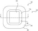
参考图1,图1为传感器导入组件100的透视图。在一个实例中,传感器导入组件100包括生理特性传感器组件102和传感器插入器104。应当注意,在某些实施例中,传感器插入器104和生理特性传感器108可以包含在Antonio等人的共同转让的美国专利公开第2017/0290533号中描述的插入装置和传感器发射器组合件,其相关部分通过引用并入本文。在该实例中,另外参考图2,生理特性传感器组合件102包括生理特性传感器108、粘合剂皮肤贴片或粘合剂贴片110和抗重力系统112。通常,生理特性传感器组合件102的组件作为单个单元联接在一起。生理特性传感器组合件102和传感器插入器104可以包装在一起以供消费者使用。Referring to FIG. 1 , FIG. 1 is a perspective view of a sensor lead-in
传感器插入器104、生理特性传感器108和粘合剂贴片110的某些特性、方面和特征可以是常规的,并且因此将不在此详细描述。简而言之,生理特性传感器108可以作为传感器组的一部分预先连接,该传感器组还可以包括传感器电子模块(未示出),例如与输液泵、监测器装置等通信的无线发射器,其在生理特性传感器108的部分插入或部署在用户身体中之后连接到生理特性传感器108。在一个实例中,生理特性传感器108包括葡萄糖传感器122和传感器基座124。应注意,生理特性传感器108不限于葡萄糖传感器,而是,可采用各种其它生理特性传感器。葡萄糖传感器122可被提供为传感器基座124的组成部分。传感器基座124给予葡萄糖传感器122结构支撑,并且有助于葡萄糖传感器122进入用户的身体。葡萄糖传感器122为包括葡萄糖氧化酶的电化学传感器,如熟悉葡萄糖传感器技术的人所熟知的。葡萄糖氧化酶使得葡萄糖传感器122能够通过实行葡萄糖和氧气的反应来监测糖尿病患者或用户的血糖水平。同样,尽管某些实施例涉及葡萄糖传感器,但是本文描述的技术可适于与本领域已知的多种传感器中的任何一种一起使用。通常,葡萄糖传感器122可以通过传感器插入器104的插入针126定位在用户的皮下组织中以测量葡萄糖氧化酶。Certain characteristics, aspects and features of
传感器基座124联接到传感器插入器104并且联接到粘合剂贴片110。传感器基座124可移除地联接到传感器插入器104。传感器基座124还可以以容纳传感器电子模块的电气和物理接口和元件为特征,例如与输液泵、监测器装置等通信的无线发射器。在某些实施例中,传感器基座124至少部分由塑料材料构成对于这里描述的实施例,传感器基座124的大部分形成为模制塑料部件。在一个实例中,传感器基座124由丙烯腈丁二烯苯乙烯、尼龙、丙烯腈丁二烯苯乙烯聚碳酸酯共混物、聚氯乙烯、聚四氟乙烯(PTFE)、聚丙烯、聚醚醚酮(PEEK)、聚碳酸酯等形成。The
粘合剂贴片110联接到传感器基座124,并将传感器基座124,因此将葡萄糖传感器122固定到解剖结构,例如用户的皮肤。粘合剂贴片110在包装和运输期间包含在传感器插入器104内,并且暴露于重力G。粘合剂贴片110可以由具有一个或多个粘合剂层的柔性透气材料构成,例如布、绷带状材料等。举例而言,合适的材料可包括聚氨酯、聚乙烯、聚酯、聚丙烯、聚四氟乙烯(PTFE)或其它聚合物,在所述材料上施加一个或多个粘合层。The
传感器插入器104联接到生理特性传感器108,并且可通过用户操作以将葡萄糖传感器122联接到用户。继续参考图2,传感器插入器104包括壳体130、支架或监测器支撑件132、一个或多个偏置部件或弹簧134以及盖或罩136。例如,在一个实例中,壳体130围绕生理特性传感器组合件102并包围生理特性传感器组合件102以使得能够对生理特性传感器组合件102进行消毒。壳体130可以包括一个或多个特征,例如可移动的突出部,其与监测器支撑件132配合以将生理特性传感器108部署到解剖结构中。监测器支撑件132联接到生理特性传感器108,并且可相对于壳体130移动以将生理特性传感器108部署到解剖结构中。例如,向壳体130施加的力可以偏置突出部以释放监测器支撑件132,使得与监测器支撑件132相关联的弹簧134能够驱动监测器支撑件132以将生理特性传感器108部署到解剖结构中。一旦释放,另一弹簧134b与监测器支撑件132配合以相对于壳体130移动针牵引器131。罩136围绕壳体130的周向开口端,并包围壳体130。通常,罩136联接到壳体130,使得粘合剂贴片110不受罩136支撑。如将要讨论的,抗重力系统112抑制或减轻重力G向下拉未支撑的粘合剂贴片110,这进而抑制或减轻粘合剂贴片110在传感器插入器104内的下垂或下陷,从而确保在整个粘合剂贴片110与用户的解剖结构之间形成完全接触。
在一个实例中,参考图3,更详细地示出了抗重力系统112。图3是生理特性传感器组合件102的俯视图,其绘示了联接到粘合剂贴片110的抗重力系统112。在该实例中,抗重力系统112是低粘性粘合剂铸纸,其联接到粘合剂贴片110和监测器支撑件132(图2)。抗重力系统112包括第一顶表面140和第二底表面142,它们在折叠部144相互连接(图4)。抗重力系统112基本上是环形的,并且限定了孔146,其尺寸设置成使得抗重力系统112能够围绕传感器基座124的周边定位。通常,抗重力系统112围绕传感器基座124的整个圆周,并且可以包括狭缝148。如果需要,一旦生理特性传感器108联接到解剖结构,狭缝148使得用户能够从粘合剂贴片110移除抗重力系统112。在该实例中,狭缝148限定在包括折叠部144的抗重力系统112的端部150。折叠部144可以被配置成使得端部150延伸距离D1,该距离不同于并且小于抗重力系统112的相对端部152的距离D2。在该实例中,抗重力系统112沿粘合剂贴片110的周边110b联接到粘合剂贴片110的表面110a,并且从粘合剂贴片110的周边向传感器基座124延伸距离D3。通常,抗重力系统112与传感器基座124间隔开第四距离D4,该第四距离不同于并且小于距离D3。In one example, referring to FIG. 3 , the
在该实例中,参考图4,抗重力系统112由层状片材112a构成,低粘性粘合剂112b施加到其上。通常,低粘性粘合剂112b仅施加到层状片材112a的单个表面上,使得当折叠时,顶表面140和底表面142包括低粘性粘合剂112b,相对表面154保持未涂布有低粘性粘合剂112b。在一个实例中,层状片材112a由纸、聚涂布纸、聚合物(例如聚酯膜或HDPE膜)等构成;并且低粘性粘合剂112b由硅树脂、丙烯酸等构成。低粘性粘合剂112b可以被浇铸、涂布、涂漆或以其它方式联接到层状片材112a。沿底表面142的低粘性粘合剂112b联接或粘附到粘合剂贴片110的表面110a,而沿顶表面140的低粘性粘合剂112b联接或粘附到监测器支撑件132的表面132a(图2)。如本文所用,“低粘性”粘合剂是一种具有足够弱的粘结以使得粘合剂在其预期用途中容易分离(例如,在插入之前或之后将衬垫从粘合剂贴片分离)的粘合剂。如本文所用,“高粘性”粘合剂是一种旨在永久性粘结(即无分离)的粘合剂。例如,如本文所用,根据ASTM D6862-11标准测试方法对于粘合剂的90度抗剥离性,“低粘性”粘合剂对不锈钢的剥离力粘附力为约0.5盎司每英寸(oz/in.)至约5盎司每英寸(oz/in.),并且根据ASTM D6862-11标准测试方法对于粘合剂的90度抗剥离性,“高粘性”粘合剂对不锈钢的剥离力粘附力大于5盎司每英寸(oz/in.)。In this example, referring to Figure 4, the
在一个实例中,在生理特性传感器108被组装并且联接到粘合剂贴片110并且形成抗重力系统112的情况下,底表面142上的低粘性粘合剂112b联接到粘合剂贴片110以便围绕传感器基座124。顶表面140在折叠部144折叠在底表面142上。参考图3,在生理特性传感器组合件102被组装,并且弹簧134和监测器支撑件132联接到壳体130的情况下,生理特性传感器组合件102联接到传感器插入器104,使得低粘性粘合剂112b联接到监测器支撑件132的表面132a。在生理特性传感器组合件102联接到监测器支撑件132的情况下,罩136联接到壳体130以包围生理特性传感器组合件102。包括生理特性传感器组合件102的传感器插入器104可以被消毒并运送给终端用户。In one example, with the
一旦接收到,用户可以移除罩136以暴露生理特性传感器组合件102。用户可以操作传感器插入器104以将生理特性传感器组合件102部署到用户上。一旦部署,顶表面140上的低粘性粘合剂112b能够将传感器插入器104从生理特性传感器组合件102移除,而无需从用户解联接粘合剂贴片110。在传感器插入器104与生理特性传感器组合件102解联接并且生理特性传感器组合件102部署在用户身上的情况下,如果需要,用户可以拉动抗重力系统112的顶表面140以从粘合剂贴片110移除抗重力系统112。Once received, the user may remove
通过在顶表面140上提供低粘性粘合剂112b,传感器插入器104在部署时可从生理特性传感器108移除,而无需从用户移除粘合剂贴片110。因此,当部署生理特性传感器108时,抗重力系统112可通过粘合剂贴片110从传感器插入器104移除。此外,底表面142上的低粘性粘合剂112b允许使用更大的粘合剂贴片110,同时抑制粘合剂贴片110的下垂。在这点上,抗重力系统112增加了延伸超过传感器基座124的粘合剂贴片110的部分的结构和刚度(图3)。换言之,抗重力系统112维持粘合剂贴片110基本上垂直于传感器插入器104的纵向轴线LA1,这确保在部署粘合剂贴片110时正确地联接到用户。如果需要,折叠部144还允许用户在部署时移除抗重力系统112。By providing the low tack adhesive 112b on the
应当注意,在其它实施例中,抗重力系统112可以被不同地配置以抑制或减轻重力对粘合剂贴片110的影响。例如,参考图5,示出了传感器引入组合件200。由于传感器引入组合件200包括与关于图1至4讨论的传感器引入组合件100相同或类似的组件,所以相同的附图标记将用于表示相同或类似的组件。图5是从图1的线2-2的透视图截取的示意性剖视图。在该实例中,传感器引入组合件200包括生理特性传感器组合件202和传感器插入器204。在该实例中,生理特性传感器组合件202包括生理特性传感器108、粘合剂贴片110和抗重力系统212。通常,生理特性传感器组合件102的组件作为单个单元联接在一起。生理特性传感器组合件202和传感器插入器204可以包装在一起以供消费者使用。It should be noted that in other embodiments, the
生理特性传感器108包括葡萄糖传感器122和传感器基座124。通常,葡萄糖传感器122可以通过传感器插入器204的插入针定位在用户的皮下组织中以测量葡萄糖氧化酶。传感器基座124联接到传感器插入器204并且联接到粘合剂贴片110。传感器基座124可移除地联接到传感器插入器204。粘合剂贴片110联接到传感器基座124,并且将传感器基座124并且因此将葡萄糖传感器122附连到用户的皮肤。粘合剂贴片110在包装和运输期间包含在传感器插入器204内,并且暴露于重力G。
传感器插入器204联接到生理特性传感器108,并且可通过用户操作以将葡萄糖传感器122联接到用户。简言之,传感器插入器204包括壳体230、监测器支撑件232和盖或罩236。例如,在一个实例中,壳体230围绕生理特性传感器组合件202并包围生理特性传感器组合件202以使得能够对生理特性传感器组合件202进行消毒。壳体230可以包括一个或多个特征,其与监测器支撑件232配合以将生理特性传感器108部署到解剖结构中。监测器支撑件232联接到生理特性传感器108,并且通过用户操作以部署生理特性传感器108。罩236围绕壳体230的周向开口端,并包围壳体230。通常,罩236联接到壳体230,使得粘合剂贴片110不受罩236支撑。如将要讨论的,抗重力系统212抑制或减轻重力G向下拉未支撑的粘合剂贴片110,这进而抑制或减轻粘合剂贴片110在传感器插入器104内的下垂或下陷,从而确保在整个粘合剂贴片110与用户的解剖结构之间形成完全接触。Sensor inserter 204 is coupled to
在一个实例中,参考图6,更详细地示出了抗重力系统212。图6是生理特性传感器组合件202的俯视图,其绘示了联接到粘合剂贴片110的抗重力系统212。参照图6和8,抗重力系统212包括第一顶表面240和第二底表面242(图8)。在图8中,为了清楚起见,移除了粘合剂贴片110。抗重力系统212基本上是环形的,并且限定了孔246,其尺寸设置成使得抗重力系统212能够围绕传感器基座124的周边定位。通常,抗重力系统212围绕传感器基座124的整个圆周。在该实例中,参考图7,抗重力系统212沿粘合剂贴片110的周边110b联接到粘合剂贴片110的表面110a,并且从粘合剂贴片110的周边向传感器基座124延伸距离D5。通常,抗重力系统212与传感器基座124间隔开第六距离D6,该第六距离不同于并且小于距离D5。In one example, referring to FIG. 6 , the
在该实例中,抗重力系统212是双面差动粘合剂,其包括联接到低粘性粘合剂层252的高粘性粘合剂层250。高粘性粘合剂层250联接到监测器支撑件232(图5),并且低粘性粘合剂层252联接到粘合剂贴片110。在该实例中,高粘性粘合剂250a联接到或形成在基座层的相对侧上。基座层由纸、聚涂布纸、聚合物(例如聚酯膜或HDPE膜)等构成。抗重力系统212的顶表面240由高粘性粘合剂层250的一侧250b限定,其联接到或形成在基座层上。在一个实例中,高粘性粘合剂250a由硅树脂、丙烯酸等构成。高粘性粘合剂250a可以被浇铸、涂布、涂漆或以其它方式联接到基座层。形成在基座层上的高粘性粘合剂层250的相对侧250c联接或粘附到低粘性粘合剂层252。In this example, the
在该实例中,低粘性粘合剂252a联接到或形成在第二基座层的相对侧上。抗重力系统212的底表面242由低粘性粘合剂层252的一侧252b限定,其联接到或形成在第二基座层上。第二基座层由纸、聚涂布纸、聚合物(例如聚酯膜或HDPE膜)构成。在一个实例中,低粘性粘合剂252a由硅树脂、丙烯酸等构成。低粘性粘合剂252a可以被浇铸、涂布、涂漆或以其它方式联接到第二基座层。形成在第二基座层上的低粘性粘合剂层252的相对侧252c联接或粘附到高粘性粘合剂层250的侧250c以形成抗重力系统212。因此,高粘性粘合剂250a是第一粘性粘合剂,并且低粘性粘合剂252a是第二粘性粘合剂,其中第二粘性粘合剂不同于并且小于第一粘性粘合剂。应当注意,为了便于说明,在附图中没有示出基座层和第二基座层,因为这些纸或膜层具有预定的标称厚度。In this example, the low tack adhesive 252a is coupled to or formed on the opposite side of the second base layer. The
在一个实例中,在生理特性传感器108被组装并且联接到粘合剂贴片110并且形成抗重力系统212的情况下,参考图5,底表面242上的低粘性粘合剂层252联接到粘合剂贴片110以便围绕传感器基座124。在生理特性传感器组合件202被组装并且监测器支撑件232联接到壳体230的情况下,生理特性传感器组合件202联接到传感器插入器204,使得高粘性粘合剂层250联接到监测器支撑件232的表面232a。在生理特性传感器组合件202联接到监测器支撑件232的情况下,罩236联接到壳体230以包围生理特性传感器组合件202。包括生理特性传感器组合件202的传感器插入器204可以被消毒并运送给终端用户。In one example, with the
一旦接收到,用户可以移除罩236以暴露生理特性传感器组合件202。用户可以操作传感器插入器204以将生理特性传感器组合件202部署到用户上。一旦部署,顶表面240上的高粘性粘合剂层250将抗重力系统212保留在传感器插入器204上,并且低粘性粘合剂层252能够从粘合剂贴片110移除抗重力系统212,而无需从用户解联接粘合剂贴片110。因此,当部署生理特性传感器108时,抗重力系统212可通过传感器插入器204从粘合剂贴片110移除。当生理特性传感器108通过粘合剂贴片110联接到用户时,抗重力系统212的差动粘合剂使得传感器插入器204能够与生理特性传感器108解联接,而无需从用户解联接生理特性传感器108和粘合剂贴片110。Once received, the user may remove
通过在顶表面240上提供高粘性粘合剂层250并且在底表面242上提供低粘性粘合剂层252,抗重力系统212保留在传感器插入器204上并且在部署时可从生理特性传感器108移除,而无需从用户移除粘合剂贴片110。此外,底表面242上的低粘性粘合剂层252允许使用较大的粘合剂贴片110,同时抑制粘合剂贴片110的下垂。在这点上,抗重力系统212增加了延伸超过传感器基座124的粘合剂贴片110的部分的结构和刚度。换言之,抗重力系统212维持粘合剂贴片110基本上垂直于传感器插入器204的纵向轴线LA2,这确保在部署粘合剂贴片110时正确地联接到用户。By providing a high tack
应当注意,在其它实施例中,抗重力系统112可以被不同地配置以抑制或减轻重力对粘合剂贴片110的影响。例如,参考图9,示出了传感器引入组合件300。由于传感器引入组合件300包括与关于图1至4讨论的传感器引入组合件100和关于图5至8讨论的传感器引入组合件200相同或类似的组件,相同的附图标记将用于表示相同或类似的组件。图9是从图1的线2-2的透视图截取的示意性剖视图。在该实例中,传感器引入组合件300包括生理特性传感器组合件302和传感器插入器204。在该实例中,生理特性传感器组合件302包括生理特性传感器108、粘合剂贴片110和抗重力系统312。通常,生理特性传感器组合件302的组件作为单个单元联接在一起。生理特性传感器组合件302和传感器插入器204可以包装在一起以供消费者使用。It should be noted that in other embodiments, the
生理特性传感器108包括葡萄糖传感器122和传感器基座124。传感器基座124联接到传感器插入器204并且联接到粘合剂贴片110。传感器基座124可移除地联接到传感器插入器204。粘合剂贴片110联接到传感器基座124,并且将传感器基座124并且因此将葡萄糖传感器122附连到用户的皮肤。粘合剂贴片110在包装和运输期间包含在传感器插入器204内,并且暴露于重力G。
传感器插入器204联接到生理特性传感器108,并且可通过用户操作以将葡萄糖传感器122联接到用户。简言之,传感器插入器204包括壳体230、监测器支撑件232和盖或罩236。例如,在一个实例中,壳体230围绕生理特性传感器组合件302并包围生理特性传感器组合件302以使得能够对生理特性传感器组合件302进行消毒。壳体230可以包括一个或多个特征,其与监测器支撑件232配合以将生理特性传感器108部署到解剖结构中。监测器支撑件232联接到生理特性传感器108,并且通过用户操作以部署生理特性传感器108。罩236围绕壳体230的周向开口端,并包围壳体230。通常,罩236联接到壳体230,使得粘合剂贴片110不受罩236支撑。如将要讨论的,抗重力系统312抑制或减轻重力G向下拉未支撑的粘合剂贴片110,这进而抑制或减轻粘合剂贴片110在传感器插入器204内的下垂或下陷,从而确保在整个粘合剂贴片110与用户的解剖结构之间形成完全接触。Sensor inserter 204 is coupled to
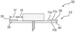
在一个实例中,参考图10,更详细地示出了抗重力系统312。图10是生理特性传感器组合件302的俯视图,其绘示了联接到粘合剂贴片110的抗重力系统312。参照图10和11,抗重力系统312包括第一顶表面340和第二底表面342(图11)。抗重力系统312基本上是环形的,并且限定了孔346,其尺寸设置成使得抗重力系统312能够围绕传感器基座124的周边定位(图10)。通常,抗重力系统312围绕传感器基座124的整个圆周。在该实例中,参考图11,抗重力系统312沿粘合剂贴片110的周边110b联接到粘合剂贴片110的表面110a,并且从粘合剂贴片110的周边向传感器基座124延伸距离D7。通常,抗重力系统312与传感器基座124间隔开第八距离D8,该第八距离不同于并且小于距离D7。In one example, referring to FIG. 10 , the
在该实例中,抗重力系统312是单层双面差动粘合剂,其包括在第一侧312a上的高粘性粘合剂350和在第二侧312b上的低粘性粘合剂352。高粘性粘合剂350联接到监测器支撑件332(图9),并且低粘性粘合剂352联接到粘合剂贴片110。在该实例中,高粘性粘合剂350和低粘性粘合剂352均联接到或形成在基座层的相对侧上。基座层由纸、聚涂布纸、聚合物(例如聚酯膜或HDPE膜)构成。抗重力系统312的顶表面340由高粘性粘合剂350限定并且抗重力系统312的底表面342由低粘性粘合剂352限定,它们联接到或形成在基座层的相对侧上。在一个实例中,高粘性粘合剂350由合成橡胶粘合剂、丙烯酸等构成。高粘性粘合剂350可以被浇铸、涂布、涂漆或以其它方式联接到基座层。低粘性粘合剂352联接到或形成在基座层的第二相对侧上。在一个实例中,低粘性粘合剂352由硅树脂、丙烯酸等构成。低粘性粘合剂352可以被铸造、涂布、涂漆或以其它方式联接到基座层。应当注意,为了便于说明,在附图中没有示出基座层,因为该纸或膜层具有预定的标称厚度。In this example, the
在一个实例中,在生理特性传感器108被组装并且联接到粘合剂贴片110并且形成抗重力系统312的情况下,参考图9,底表面342上的低粘性粘合剂352联接到粘合剂贴片110以便围绕传感器基座124。在生理特性传感器组合件302被组装并且监测器支撑件232联接到壳体230的情况下,生理特性传感器组合件302联接到传感器插入器204,使得高粘性粘合剂350联接到监测器支撑件232的表面232a。在生理特性传感器组合件302联接到监测器支撑件232的情况下,罩236联接到壳体230以包围生理特性传感器组合件302。包括生理特性传感器组合件302的传感器插入器204可以被消毒并运送给终端用户。In one example, with the
一旦接收到,用户可以移除罩236以暴露生理特性传感器组合件302。用户可以操作传感器插入器204以将生理特性传感器组合件302部署到用户上。一旦部署,顶表面340上的高粘性粘合剂350将抗重力系统312保留在传感器插入器204上,并且低粘性粘合剂352能够从粘合剂贴片110移除抗重力系统312,而无需将粘合剂贴片110与用户解联接。因此,当生理特性传感器108通过粘合剂贴片110联接到用户时,抗重力系统312的差动粘合剂使得传感器插入器204能够与生理特性传感器108解联接,而无需从用户解联接生理特性传感器108和粘合剂贴片110。Once received, the user may remove
通过在顶表面340上提供高粘性粘合剂350并且在底表面342上提供低粘性粘合剂352,抗重力系统312保留在传感器插入器204上并且在部署时可从生理特性传感器108移除,而无需从用户移除粘合剂贴片110。因此,当部署生理特性传感器108时,抗重力系统312可通过传感器插入器204从粘合剂贴片110移除。此外,底表面342上的低粘性粘合剂352允许使用较大的粘合剂贴片110,同时抑制粘合剂贴片110的下垂。在这点上,抗重力系统312增加了延伸超过传感器基座124的粘合剂贴片110的部分的结构和刚度。换言之,抗重力系统312维持粘合剂贴片110基本上垂直于传感器插入器204的纵向轴线LA2,这确保在部署粘合剂贴片110时正确地联接到用户。By providing high tack adhesive 350 on
应当注意,在其它实施例中,抗重力系统112可以被不同地配置以抑制或减轻重力对粘合剂贴片110的影响。例如,参考图12,示出了传感器引入组合件400。由于传感器引入组合件400包括与关于图1至4讨论的传感器引入组合件100和关于图5至8讨论的传感器引入组合件200相同或类似的组件,相同的附图标记将用于表示相同或类似的组件。图12是从图1的线2-2的透视图截取的示意性剖视图。在该实例中,传感器引入组合件400包括生理特性传感器组合件402和传感器插入器204。在该实例中,生理特性传感器组合件402包括生理特性传感器108、粘合剂贴片110和抗重力系统412。通常,生理特性传感器组合件402的组件作为单个单元联接在一起。生理特性传感器组合件402和传感器插入器204可以包装在一起以供消费者使用。It should be noted that in other embodiments, the
生理特性传感器108包括葡萄糖传感器122和传感器基座124。传感器基座124联接到传感器插入器204并且联接到粘合剂贴片110。传感器基座124可移除地联接到传感器插入器204。粘合剂贴片110联接到传感器基座124,并且将传感器基座124并且因此将葡萄糖传感器122附连到用户的皮肤。粘合剂贴片110在包装和运输期间包含在传感器插入器204内,并且暴露于重力G。
传感器插入器204联接到生理特性传感器108,并且可通过用户操作以将葡萄糖传感器122联接到用户。简言之,传感器插入器204包括壳体230、监测器支撑件232和盖或罩236。例如,在一个实例中,壳体230围绕生理特性传感器组合件202并包围生理特性传感器组合件202以使得能够对生理特性传感器组合件202进行消毒。壳体230可以包括一个或多个特征,其与监测器支撑件232配合以将生理特性传感器108部署到解剖结构中。监测器支撑件232联接到生理特性传感器108,并且通过用户操作以将生理特性传感器108部署到解剖结构中。罩236围绕壳体230的周向开口端,并包围壳体230。通常,罩236联接到壳体230,使得粘合剂贴片110不受罩236支撑。如将要讨论的,抗重力系统412抑制或减轻重力G向下拉未支撑的粘合剂贴片110,这进而抑制或减轻粘合剂贴片110在传感器插入器204内的下垂或下陷,从而确保在整个粘合剂贴片110与用户的解剖结构之间形成完全接触。Sensor inserter 204 is coupled to
在一个实例中,参考图13,更详细地示出了抗重力系统412。图13是生理特性传感器组合件402的俯视图,其绘示了联接到粘合剂贴片110的抗重力系统412。在该实例中,抗重力系统412包括多个粘合剂条414,这些粘合剂条围绕传感器基座124的周边间隔开。多个粘合剂条414也围绕粘合剂贴片110的周边或圆周间隔开。在该实例中,抗重力系统412包括四个粘合剂条414,但应当理解,抗重力系统412可以包括任何数量的粘合剂条414。In one example, referring to Figure 13, the anti-gravity system 412 is shown in more detail. FIG. 13 is a top view of the physiological
粘合剂条414中的每一个包括第一顶表面440和第二底表面442(图14)。粘合剂条414中的每一个是矩形的,具有圆形边缘。然而,应当注意,粘合剂条414可以具有任何期望的形状,并且进一步,粘合剂条414中的一个或多个可以具有不同的形状。在该实例中,粘合剂条414中的每一个具有长度L1和宽度W1。长度L1和宽度W1均被预定义以确保粘合剂带414为粘合剂贴片110提供刚度,同时还确保粘合剂带414不干扰粘合剂贴片110从传感器插入器204的移除,如以下将讨论的。在一个实例中,长度L1为约100微米(μm)至约1.0毫米(mm);并且宽度W1为约100微米(μm)至约5.0毫米(mm)。通常,粘合剂条414的尺寸和位置设置成与监测器支撑件232相接。粘合剂条414中的每一个被定位成距粘合剂贴片110的周边110b距离D9,并且距传感器基座124的周边距离D10。在一个实例中,距离D9约等于或等于距离D10,并且为约0毫米(mm)至约10毫米(mm)。Each of the
在该实例中,粘合剂条414中的每一个包含差动双面粘合剂,其包括在顶表面440上的高粘性粘合剂450和在底表面442上的低粘性粘合剂452。顶表面440上的高粘性粘合剂450联接到监测器支撑件232(图12),并且底表面442上的低粘性粘合剂452联接到粘合剂贴片110。抗重力系统412的顶表面440由高粘性粘合剂450限定并且抗重力系统412的底表面442由低粘性粘合剂452限定。在该实例中,高粘性粘合剂450和低粘性粘合剂452均联接到或形成在基座层的相对侧上。基座层由纸、聚涂布纸、聚合物(例如聚酯膜或HDPE膜)构成。在一个实例中,高粘性粘合剂450由合成橡胶粘合剂、丙烯酸等构成。高粘性粘合剂450可以被浇铸、涂布、涂漆或以其它方式联接到基座层。低粘性粘合剂452联接到或形成在基座层的第二相对侧上。在一个实例中,低粘性粘合剂452由硅树脂、丙烯酸等构成。低粘性粘合剂452可以被铸造、涂布、涂漆或以其它方式联接到基座层。应当注意,为了便于说明,在附图中没有示出基座层,因为该纸或膜层具有预定的标称厚度。In this example, each of the
在一个实例中,在生理特性传感器108被组装并且联接到粘合剂贴片110并且形成抗重力系统412的情况下,参考图5,粘合剂条414联接到粘合剂贴片110(经由底表面442上的低粘性粘合剂452),以便围绕粘合剂贴片110的周边110b间隔开。在生理特性传感器组合件402被组装并且监测器支撑件232联接到壳体230的情况下,生理特性传感器组合件402联接到传感器插入器204,使得顶表面440的高粘性粘合剂450联接到监测器支撑件232的表面232a。在生理特性传感器组合件402联接到监测器支撑件232的情况下,罩236联接到壳体230以包围生理特性传感器组合件402。包括生理特性传感器组合件402的传感器插入器204可以被消毒并运送给终端用户。In one example, with the
一旦接收到,用户可以移除罩236以暴露生理特性传感器组合件402。用户可以操作传感器插入器204以将生理特性传感器组合件402部署到用户上。一旦部署,顶表面440上的高粘性粘合剂450将抗重力系统412保留在传感器插入器204上。因此,当部署生理特性传感器108时,抗重力系统412可通过传感器插入器204从粘合剂贴片110移除。当生理特性传感器108通过粘合剂贴片110联接到用户时,抗重力系统412使得传感器插入器204能够与生理特性传感器108解联接,而无需从用户解联接生理特性传感器108和粘合剂贴片110。Once received, the user may remove
通过在顶表面440上提供具有高粘性粘合剂层250并且在底表面442上提供具有低粘性粘合剂层452的粘合剂条414,抗重力系统412保留在传感器插入器204上并且在部署时可从生理特性传感器108移除,而无需从用户移除粘合剂贴片110。此外,抗重力系统412允许使用较大的粘合剂贴片110,同时抑制粘合剂贴片110的下垂。在这点上,抗重力系统412增加了延伸超过传感器基座124的粘合剂贴片110的部分的结构和刚度。换言之,抗重力系统412维持粘合剂贴片110基本上垂直于传感器插入器204的纵向轴线LA2,这确保在部署粘合剂贴片110时正确地联接到用户。By providing
应当注意,在其它实施例中,抗重力系统112可以被不同地配置以抑制或减轻重力对粘合剂贴片110的影响。例如,参考图15,示出了传感器引入组合件500。由于传感器引入组合件500包括与关于图1至4讨论的传感器引入组合件100和关于图5至8讨论的传感器引入组合件200相同或类似的组件,相同的附图标记将用于表示相同或类似的组件。图15是从图1的线2-2的透视图截取的示意性剖视图。在该实例中,传感器引入组合件500包括生理特性传感器组合件502和传感器插入器504。在该实例中,生理特性传感器组合件502包括生理特性传感器108、粘合剂皮肤贴片或粘合剂贴片510和抗重力系统512。通常,生理特性传感器组合件502的组件作为单个单元联接在一起。生理特性传感器组合件502和传感器插入器504可以包装在一起以供消费者使用。It should be noted that in other embodiments, the
生理特性传感器108包括葡萄糖传感器122和传感器基座124。通常,葡萄糖传感器122可以通过传感器插入器504的插入针定位在用户的皮下组织中以测量葡萄糖氧化酶。传感器基座124联接到传感器插入器504并且联接到粘合剂贴片110。传感器基座124可移除地联接到传感器插入器204。
粘合剂贴片510联接到传感器基座124,并将传感器基座124,从而将葡萄糖传感器122固定到用户的皮肤。粘合剂贴片510在包装和运输期间包含在传感器插入器504内,并且暴露于重力G。粘合剂贴片510可以由具有一个或多个粘合剂层的柔性透气材料构成,例如布、绷带状材料等。举例而言,合适的材料可包括聚氨酯、聚乙烯、聚酯、聚丙烯、聚四氟乙烯(PTFE)或其它聚合物,在所述材料上施加一个或多个粘合层。在该实例中,粘合剂贴片510包括带电表面或第一带电表面510a。第一带电表面510a与联接到用户的表面510b相对。在一个实例中,第一带电表面510a具有正电荷,其与传感器插入器504的负电荷表面配合,如将讨论的。在其它实例中,第一带电表面510a可以具有负电荷表面,其与传感器插入器504的对应的正电荷表面配合。第一带电表面510a可以使用接触感应电荷分离、电荷感应电荷分离等来带电。对于接触感应电荷分离,所施加的电荷量和电荷极性取决于材料和表面粗糙度。
传感器插入器504联接到生理特性传感器108,并且可通过用户操作以将葡萄糖传感器122联接到用户。简言之,传感器插入器504包括壳体230、监测器支撑件532和盖或罩236。例如,在一个实例中,壳体230围绕生理特性传感器组合件502并包围生理特性传感器组合件502以使得能够对生理特性传感器组合件502进行消毒。壳体230可以包括一个或多个特征,其与监测器支撑件532配合以将生理特性传感器108部署到解剖结构中。监测器支撑件532联接到生理特性传感器108,并且通过用户操作以将生理特性传感器108部署到解剖结构中。在该实例中,监测器支撑件532包括带电表面或第二带电表面532a。第二带电表面532a面向粘合剂贴片110。在一个实例中,第二带电表面532a具有负电荷,其与粘合剂贴片510的第一带电表面510a配合。第二带电表面532a可以使用接触感应电荷分离、电荷感应电荷分离等来带电。对于接触感应电荷分离,所施加的电荷量和电荷极性取决于材料和表面粗糙度。
在接触感应电荷分离的实例中,粘合剂贴片510的第一带电表面510a由在摩擦电序列中带更多负电荷的材料(例如聚氨酯膜)构成。监测器支撑件532的第二带电表面532a由在摩擦电序列中比粘合剂贴片510的第一带电表面510a的材料带更多正电的材料(例如尼龙)构成。第一带电表面510a和第二带电表面532a之间的接触导致两个表面510a、532a之间的粘附,因为电子被交换并且通过在每个表面上积累的相反电荷而相互吸引,这抑制了粘合剂贴片510的下垂。应当注意,本文所选择的材料仅是实例,因为沿摩擦电序列彼此分离的任何材料都可以用于粘合剂贴片510和监测器支撑件532,只要第一带电表面510a和第二带电表面532a之间的接触由于电子交换和由于在相应表面510a、532a上积累的相反电荷的吸引而导致两个表面510a、532a之间的粘附。应当注意,监测器支撑件532的整体可以由预定材料构成,或仅监测器支撑件532的表面(例如第二带电表面532a)可以由预定材料形成。In the example of contact induced charge separation, the first charged
在电荷感应电荷分离的实例中,第一带电表面510a最初可以由电中性材料(例如已经电接地以具有净中性电荷的聚酯)构成。带负电荷的物体可以被带到第一带电表面510a附近,以在与第一带电表面510a相关联的正电荷向带负电的物体移动时在第一带电表面510a上感应正电荷。类似地,第二带电表面532a可以由电中性材料(例如已经电接地以具有净中性电荷的聚碳酸酯)构成。带正电荷的物体可以被带到第二带电表面532a附近,以在与第一带电表面510a相关联的负电荷向带正电的物体移动时在第二带电表面532a上感应负电荷。当生理特性传感器108联接到传感器插入器504时,带负电的第二带电表面532a吸引带正电的第一带电表面510a,这抑制了粘合剂贴片510的下垂。In the case of charge-induced charge separation, the first charged
罩236围绕壳体230的周向开口端,并包围壳体230。通常,罩236联接到壳体230,使得粘合剂贴片510不受罩236支撑。如所讨论的,抗重力系统512抑制或减轻重力G向下拉未支撑的粘合剂贴片510,这进而抑制或减轻粘合剂贴片510在传感器插入器204内的下垂或下陷,从而确保在整个粘合剂贴片510与用户的解剖结构之间形成完全接触。The
在一个实例中,在生理特性传感器108被组装并联接到粘合剂贴片510并且形成抗重力系统512的情况下,第一带电表面510a被充电以具有相应的电荷,在该实例中为正电荷。监测器支撑件532的第二带电表面532a被充电以具有相应的电荷,在该实例中为负电荷。在生理特性传感器组合件502被组装并且监测器支撑件532联接到壳体230的情况下,生理特性传感器组合件502联接到传感器插入器504,使得粘合剂贴片510的第一带电表面510a被电吸引到监测器支撑件532的第二带电表面532a。在生理特性传感器组合件502联接到监测器支撑件532的情况下,罩236联接到壳体230以包围生理特性传感器组合件502。包括生理特性传感器组合件502的传感器插入器504可以被消毒并运送给终端用户。In one example, with the
一旦接收到,用户可以移除罩236以暴露生理特性传感器组合件502。用户可以操作传感器插入器504以将生理特性传感器组合件502部署到用户上。第一带电表面510a和第二带电表面532a之间的弱吸引力使得传感器插入器504能够从生理特性传感器组合件502移除。因此,当生理特性传感器108通过粘合剂贴片510联接到用户时,抗重力系统512使得传感器插入器504能够与生理特性传感器108解联接,而无需从用户解联接生理特性传感器108和粘合剂贴片510。进一步,通过在第一带电表面510a和第二带电表面532a之间提供吸引力,抗重力系统512允许使用较大的粘合剂贴片110,同时抑制粘合剂贴片510的下垂。在这点上,第一带电表面510a和第二带电表面532a之间的吸引力维持粘合剂贴片510基本上垂直于传感器插入器504的纵向轴线LA5,这确保在部署粘合剂贴片510时正确地联接到用户。换言之,粘合剂贴片510包括第一带电表面或具有第一电荷的第一带电表面510a,在该实例中为正电荷,传感器插入器504包括第二带电表面或具有第二电荷的第二带电表面532a,在该实例中为负电荷,并且第一电荷不同于第二电荷以维持粘合剂贴片510基本上垂直于传感器插入器504的纵向轴线LA5。Once received, the user may remove
应当注意,本文描述和绘示的传感器插入器104、204、504仅是示范性的,因为任何装置可以与抗重力系统112、212、312、412、512一起使用以将生理特性传感器108部署到解剖结构中。例如,示范性传感器插入器可以仅包括监测器支撑件,例如监测器支撑件232、532,其通过用户手动操作以将生理特性传感器108部署到解剖结构中。此外,应当注意,传感器插入器204、504可以包含关于图1至4讨论的传感器插入器104或在Antonio等人的共同转让的美国专利公开第2017/0290533号中描述的插入装置,其相关部分先前通过引用并入本文。It should be noted that the
虽然前述具体实施方式中已经呈现了至少一个示例性实施例,但是应当理解,存在大量变化。还应当理解,本文中描述的一个或多个示例性实施例并非旨在以任何方式限制所要求保护的主题的范围、适用性或配置。更准确地说,前述具体实施方式将向本领域的技术人员提供用于实施所描述的一个或多个实施例的方便的指南。应理解,可在不脱离由权利要求书所限定的范围的情况下对元件的功能和布置作出各种改变,权利要求书所限定的范围包括于提交本专利申请时的已知等效物和可预见的等效物。While at least one exemplary embodiment has been presented in the foregoing Detailed Description, it should be appreciated that a vast number of variations exist. It should also be appreciated that the exemplary embodiment or embodiments described herein are not intended to limit the scope, applicability, or configuration of the claimed subject matter in any way. Rather, the foregoing detailed description will provide those skilled in the art with a convenient guide for implementing the described embodiment or embodiments. It should be understood that various changes can be made in the function and arrangement of elements without departing from the scope defined by the claims, which include known equivalents and foreseeable equivalents.
应理解,本文所公开的各个方面可以不同的组合而非说明书和附图中具体呈现的组合进行组合。还应理解的是,依据示例,本文所描述的过程或方法中的任一个的某些动作或事件可按不同顺序执行,可被添加、合并或完全省略(例如,所有描述的动作或事件对于执行技术可能不是必需的)。另外,尽管为了清楚起见将本公开的某些方面描述为由单个模块或单元来执行,但应理解,本公开的技术可以通过与例如医疗装置相关联的单元或模块的组合来执行。形成本公开的部分的进一步实施例在下面的组A和组B的段落中阐述。It should be understood that the various aspects disclosed herein may be combined in different combinations than those specifically presented in the specification and drawings. It should also be understood that, by way of example, certain acts or events of any of the processes or methods described herein may be performed in a different order, added, combined, or omitted entirely (eg, all described acts or events may be Execution techniques may not be required). Additionally, although certain aspects of the present disclosure are described for clarity as being performed by a single module or unit, it should be understood that the techniques of the present disclosure may be performed by a combination of units or modules associated with, for example, a medical device. Further embodiments forming part of this disclosure are set forth in the Group A and Group B paragraphs below.
组AGroup A
段落A1.一种用于部署有传感器插入器的生理特性传感器的系统,其包含:联接到所述生理特性传感器的粘合剂贴片,所述粘合剂贴片将所述生理特性传感器联接到解剖结构;以及联接到所述粘合剂贴片并且待联接到所述传感器插入器的抗重力系统,所述抗重力系统在部署所述生理特性传感器之前维持所述粘合剂贴片基本上垂直于所述传感器插入器的纵向轴线并且在部署所述生理特性传感器时可通过所述传感器插入器从所述粘合剂贴片移除。Paragraph A1. A system for a physiological property sensor deployed with a sensor inserter, comprising: an adhesive patch coupled to the physiological property sensor, the adhesive patch coupling the physiological property sensor to an anatomical structure; and an antigravity system coupled to the adhesive patch and to be coupled to the sensor inserter, the antigravity system maintaining the adhesive patch substantially prior to deployment of the physiological property sensor is perpendicular to the longitudinal axis of the sensor inserter and is removable from the adhesive patch by the sensor inserter when the physiological property sensor is deployed.
段落A2.根据段落A1所述的系统,其中所述抗重力系统包含至少一个粘合剂层,所述至少一个粘合剂层联接到所述粘合剂贴片的表面并且待联接到所述传感器插入器的表面。Paragraph A2. The system of paragraph Al, wherein the anti-gravity system comprises at least one adhesive layer coupled to a surface of the adhesive patch and to be coupled to the The surface of the sensor interposer.
段落A3.根据段落A2所述的系统,其中所述至少一个粘合剂层是差动双面粘合剂。Paragraph A3. The system of paragraph A2, wherein the at least one adhesive layer is a differential double-sided adhesive.
段落A4.根据段落A1、A2或A3所述的系统,其中所述至少一个粘合剂层包含多个粘合剂条,所述多个粘合剂条围绕所述粘合剂贴片的周边间隔开。Paragraph A4. The system of paragraph A1 , A2, or A3, wherein the at least one adhesive layer comprises a plurality of adhesive stripes surrounding a perimeter of the adhesive patch spaced apart.
段落A5.根据段落A2所述的系统,其中所述至少一个粘合剂层包含在第一侧上的第一粘性粘合剂和在相对侧上的第二粘性粘合剂,所述第二粘性粘合剂的粘性小于所述第一粘性粘合剂的粘性。Paragraph A5. The system of paragraph A2, wherein the at least one adhesive layer comprises a first tacky adhesive on a first side and a second tacky adhesive on an opposite side, the second tacky adhesive The tackiness of the tacky adhesive is less than the tackiness of the first tacky adhesive.
段落A6.根据段落A5所述的系统,其中所述第一粘性粘合剂待联接到所述传感器插入器,并且所述第二粘性粘合剂联接到所述粘合剂贴片。Paragraph A6. The system of paragraph A5, wherein the first tacky adhesive is to be coupled to the sensor interposer and the second tacky adhesive is coupled to the adhesive patch.
段落A7.根据段落A1所述的系统,其中所述抗重力系统包含多个粘合剂层,所述多个粘合剂层联接在所述粘合剂贴片的表面和待联接到所述传感器插入器的表面之间。Paragraph A7. The system of paragraph Al, wherein the antigravity system comprises a plurality of adhesive layers coupled to a surface of the adhesive patch and to be coupled to the between the surfaces of the sensor interposer.
段落A8.根据段落A7所述的系统,其中所述多个粘合剂层中的第一粘合剂层包含在相对侧上的第一粘性粘合剂,并且所述多个粘合剂层中的第二粘合剂层包含在相对侧上的第二粘性粘合剂,所述第二粘性粘合剂的粘性小于所述第一粘性粘合剂的粘性。Paragraph A8. The system of paragraph A7, wherein a first adhesive layer of the plurality of adhesive layers comprises a first tacky adhesive on opposite sides, and the plurality of adhesive layers The second adhesive layer in includes a second tacky adhesive on the opposite side, the second tacky adhesive being less tacky than the first tacky adhesive.
段落A9.根据段落A8所述的系统,其中所述第一粘性粘合剂待联接到所述传感器插入器,并且所述第二粘性粘合剂联接到所述粘合剂贴片。Paragraph A9. The system of paragraph A8, wherein the first tacky adhesive is to be coupled to the sensor interposer and the second tacky adhesive is coupled to the adhesive patch.
段落A10.根据段落A1所述的系统,其中所述粘合剂贴片包括具有第一电荷的第一带电表面,所述传感器插入器包括具有第二电荷的第二带电表面,并且所述第一电荷不同于所述第二电荷以维持所述粘合剂贴片基本上垂直于所述传感器插入器的所述纵向轴线。Paragraph A10. The system of paragraph A1, wherein the adhesive patch includes a first charged surface having a first charge, the sensor interposer includes a second charged surface having a second charge, and the first A charge is different from the second charge to maintain the adhesive patch substantially perpendicular to the longitudinal axis of the sensor interposer.
段落A11.一种用于部署有传感器插入器的生理特性传感器的系统,其包含:联接到所述生理特性传感器的粘合剂贴片,所述粘合剂贴片将所述生理特性传感器联接到解剖结构;以及联接到所述粘合剂贴片和所述传感器插入器的抗重力系统,所述抗重力系统包括联接在所述粘合剂贴片和所述传感器插入器之间的至少一个粘合剂层,所述至少一个粘合剂层联接到所述粘合剂层的表面以便围绕所述粘合剂贴片的周边的至少部分定位,并且所述抗重力系统在部署所述生理特性传感器之前维持所述粘合剂贴片基本上垂直于所述传感器插入器的纵向轴线,并且在部署所述生理特性传感器时可通过所述传感器插入器从所述粘合剂贴片移除。Paragraph A11. A system for a physiological property sensor deployed with a sensor inserter, comprising: an adhesive patch coupled to the physiological property sensor, the adhesive patch coupling the physiological property sensor to an anatomical structure; and an anti-gravity system coupled to the adhesive patch and the sensor inserter, the anti-gravity system comprising at least a an adhesive layer coupled to a surface of the adhesive layer so as to be positioned around at least a portion of the perimeter of the adhesive patch, and the anti-gravity system is deploying the maintaining the adhesive patch substantially perpendicular to the longitudinal axis of the sensor inserter prior to the physiological property sensor and removable from the adhesive patch by the sensor inserter when the physiological property sensor is deployed remove.
段落A12.根据段落A11所述的系统,其中所述至少一个粘合剂层是差动双面粘合剂并包含多个粘合剂条,所述多个粘合剂条围绕所述粘合剂贴片的所述周边间隔开。Paragraph A12. The system of paragraph A11, wherein the at least one adhesive layer is a differential double-sided adhesive and comprises a plurality of adhesive strips surrounding the adhesive The perimeter of the patch is spaced apart.
段落A13.根据段落A11所述的系统,其中所述至少一个粘合剂层是差动双面粘合剂层。Paragraph A13. The system of paragraph A11, wherein the at least one adhesive layer is a differential double-sided adhesive layer.
段落A14.根据段落A13所述的系统,其中所述至少一个粘合剂层包含在第一侧上的第一粘性粘合剂和在相对侧上的第二粘性粘合剂,所述第二粘性粘合剂的粘性小于所述第一粘性粘合剂的粘性,并且所述第一粘性粘合剂联接到所述传感器插入器,并且所述第二粘性粘合剂联接到所述粘合剂贴片。Paragraph A14. The system of paragraph A13, wherein the at least one adhesive layer comprises a first tacky adhesive on a first side and a second tacky adhesive on an opposite side, the second tacky adhesive the tacky adhesive is less tacky than the first tacky adhesive, and the first tacky adhesive is coupled to the sensor interposer and the second tacky adhesive is coupled to the bond patch.
段落A15.根据段落A11所述的系统,其中所述抗重力系统包含多个粘合剂层,所述多个粘合剂层联接在所述粘合剂贴片的表面和所述传感器插入器的表面之间,其中所述多个粘合剂层中的第一粘合剂层包含在相对侧上的第一粘性粘合剂,并且所述多个粘合剂层中的第二粘合剂层包含在相对侧上的第二粘性粘合剂,所述第二粘性粘合剂小于所述第一粘性粘合剂,所述第一粘性粘合剂联接到所述传感器插入器,并且所述第二粘性粘合剂联接到所述粘合剂贴片。Paragraph A15. The system of paragraph A11, wherein the anti-gravity system comprises a plurality of adhesive layers coupled to a surface of the adhesive patch and the sensor interposer between the surfaces, wherein a first adhesive layer of the plurality of adhesive layers comprises a first tacky adhesive on opposite sides, and a second adhesive layer of the plurality of adhesive layers the agent layer includes a second tacky adhesive on an opposite side, the second tacky adhesive being smaller than the first tacky adhesive, the first tacky adhesive being coupled to the sensor interposer, and The second tacky adhesive is coupled to the adhesive patch.
段落A16.一种用于部署有传感器插入器的生理特性传感器的系统,其包含:联接到所述生理特性传感器的粘合剂贴片,所述粘合剂贴片将所述生理特性传感器联接到解剖结构;以及联接到所述粘合剂贴片和所述传感器插入器的抗重力系统,所述抗重力系统包括联接在所述粘合剂贴片和所述传感器插入器之间的至少一个粘合剂层,所述至少一个粘合剂层联接到所述粘合剂层的表面以便围绕所述粘合剂贴片的周边定位,所述至少一个粘合剂层包含在第一侧上的第一粘性粘合剂和在相对侧上的第二粘性粘合剂,所述第二粘性粘合剂的粘性小于所述第一粘性粘合剂的粘性,并且所述抗重力系统在部署所述生理特性传感器之前维持所述粘合剂贴片基本上垂直于传感器插入器的纵向轴线,并且在部署生理特性传感器部时可通过所述传感器插入器从所述粘合剂贴片移除。Paragraph A16. A system for a physiological property sensor deployed with a sensor inserter, comprising: an adhesive patch coupled to the physiological property sensor, the adhesive patch coupling the physiological property sensor to an anatomical structure; and an anti-gravity system coupled to the adhesive patch and the sensor inserter, the anti-gravity system comprising at least a an adhesive layer coupled to a surface of the adhesive layer for positioning around the perimeter of the adhesive patch, the at least one adhesive layer contained on the first side a first tacky adhesive on the opposite side and a second tacky adhesive on the opposite side, the second tacky adhesive being less tacky than the first tacky adhesive, and the antigravity system is maintaining the adhesive patch substantially perpendicular to the longitudinal axis of the sensor inserter prior to deployment of the physiological property sensor and removable from the adhesive patch by the sensor inserter when deploying the physiological property sensor portion remove.
段落A17.根据段落A16所述的系统,其中所述第一粘性粘合剂联接到所述传感器插入器并且所述第二粘性粘合剂联接到所述粘合剂贴片。Paragraph A17. The system of paragraph A16, wherein the first tacky adhesive is coupled to the sensor interposer and the second tacky adhesive is coupled to the adhesive patch.
段落A18.根据段落A17所述的系统,其中所述抗重力系统包含多个粘合剂层,所述多个粘合剂层联接在所述粘合剂贴片的表面和所述传感器插入器的表面之间,其中所述多个粘合剂层中的第一粘合剂层包含限定所述第一侧的所述第一粘性粘合剂,并且所述多个粘合剂层中的第二粘合剂层包含限定所述第二侧的所述第二粘性粘合剂。Paragraph A18. The system of paragraph A17, wherein the anti-gravity system comprises a plurality of adhesive layers coupled to a surface of the adhesive patch and the sensor interposer between surfaces, wherein a first adhesive layer of the plurality of adhesive layers comprises the first tacky adhesive defining the first side, and a first adhesive layer of the plurality of adhesive layers A second adhesive layer includes the second tacky adhesive defining the second side.
组BGroup B
段落B1.一种用于部署有传感器插入器的生理特性传感器的系统,其包含:联接到所述生理特性传感器的粘合剂贴片,所述粘合剂贴片将所述生理特性传感器联接到解剖结构;以及Paragraph B1. A system for a physiological property sensor deployed with a sensor inserter, comprising: an adhesive patch coupled to the physiological property sensor, the adhesive patch coupling the physiological property sensor to anatomy; and
联接到所述粘合剂贴片并且待联接到所述传感器插入器的抗重力系统,所述抗重力系统在部署所述生理特性传感器之前维持所述粘合剂贴片基本上垂直于所述传感器插入器的纵向轴线,并且在部署所述生理特性传感器时,所述抗重力系统可通过所述粘合剂贴片从所述传感器插入器移除。an anti-gravity system coupled to the adhesive patch and to be coupled to the sensor inserter, the anti-gravity system maintaining the adhesive patch substantially perpendicular to the The longitudinal axis of the sensor inserter, and upon deployment of the physiological property sensor, the anti-gravity system is removable from the sensor inserter through the adhesive patch.
段落B2.根据段落B1所述的系统,其中所述抗重力系统包含粘合剂纸,所述粘合剂纸联接在所述粘合剂贴片和所述传感器插入器之间。Paragraph B2. The system of paragraph Bl, wherein the anti-gravity system comprises an adhesive paper coupled between the adhesive patch and the sensor interposer.
段落B3.根据段落B1或B2所述的系统,其中所述抗重力系统包括与第二表面相对的第一表面,并且限定穿过所述第一表面和所述第二表面的孔以使得所述抗重力系统能够围绕所述生理特性传感器的周边定位。Paragraph B3. The system of paragraph B1 or B2, wherein the anti-gravity system includes a first surface opposite a second surface and defines apertures through the first and second surfaces such that all The anti-gravity system can be positioned around the perimeter of the physiological property sensor.
段落B4.根据段落B3所述的系统,其中所述抗重力系统包括与第二端相对的第一端,并且所述抗重力系统包括在所述第一端的折叠部以通过将所述第一表面定位在所述第二表面上方来限定所述第一表面。Paragraph B4. The system of paragraph B3, wherein the antigravity system includes a first end opposite the second end, and the antigravity system includes a fold at the first end A surface is positioned over the second surface to define the first surface.
段落B5.根据段落B4所述的系统,其中所述抗重力系统包括在所述第一端的狭缝,所述狭缝延伸穿过所述折叠部以能够在部署之后将所述抗重力系统从所述粘合剂贴片移除。Paragraph B5. The system of paragraph B4, wherein the anti-gravity system includes a slit at the first end extending through the fold to enable the anti-gravity system after deployment removed from the adhesive patch.
段落B6.根据段落B4所述的系统,其中所述抗重力系统在所述第一端延伸第一距离并且在所述第二端延伸第二距离,所述第一距离不同于所述第二距离。Paragraph B6. The system of paragraph B4, wherein the antigravity system extends a first distance at the first end and a second distance at the second end, the first distance being different from the second distance.
段落B7.根据段落B3所述的系统,其中所述第一表面联接到所述传感器插入器并且所述第二表面联接到所述粘合剂贴片。Paragraph B7. The system of paragraph B3, wherein the first surface is coupled to the sensor interposer and the second surface is coupled to the adhesive patch.
段落B8.根据段落B1至B7中任一项所述的系统,其中所述抗重力系统包含在纸上浇注的低粘性粘合剂,其联接在所述粘合剂贴片和所述传感器插入器之间。Paragraph B8. The system of any of paragraphs B1 to B7, wherein the anti-gravity system comprises a low-tack adhesive cast on paper coupled between the adhesive patch and the sensor insert between devices.
段落B9.一种用于部署有传感器插入器的生理特性传感器的系统,其包含:联接到所述生理特性传感器的粘合剂贴片,所述粘合剂贴片将所述生理特性传感器联接到解剖结构;以及Paragraph B9. A system for a physiological property sensor deployed with a sensor inserter, comprising: an adhesive patch coupled to the physiological property sensor, the adhesive patch coupling the physiological property sensor to anatomy; and
联接到所述粘合剂贴片和所述传感器插入器的抗重力系统,所述抗重力系统包含低粘性粘合剂纸,所述低粘性粘合剂纸具有通过折叠部定位成与第二表面相对的第一表面,所述第一表面联接到所述粘合剂贴片并且所述第二表面联接到所述传感器插入器,并且所述抗重力系统在部署所述生理特性传感器之前维持所述粘合剂贴片基本上垂直于所述传感器插入器的纵向轴线,并且在部署所述生理特性传感器时,所述抗重力系统可通过所述粘合剂贴片从所述传感器插入器移除。an anti-gravity system coupled to the adhesive patch and the sensor interposer, the anti-gravity system comprising a low tack adhesive paper having a fold positioned to engage with a second a surface opposing first surface coupled to the adhesive patch and the second surface coupled to the sensor inserter and the antigravity system maintained prior to deployment of the physiological property sensor The adhesive patch is substantially perpendicular to the longitudinal axis of the sensor inserter, and the anti-gravity system is accessible from the sensor inserter through the adhesive patch when the physiological property sensor is deployed remove.
段落B10.根据段落B1所述的系统,其中所述抗重力系统限定穿过所述第一表面和所述第二表面的孔,以使得所述抗重力系统能够围绕所述生理特性传感器的周边定位。Paragraph B10. The system of paragraph B1, wherein the antigravity system defines an aperture through the first surface and the second surface to enable the antigravity system to surround the perimeter of the physiological property sensor position.
段落B11.根据段落B10所述的系统,其中所述抗重力系统包括与第二端相对的第一端,其中所述折叠在所述第一端,并且所述抗重力系统包括在所述第一端的狭缝,所述狭缝延伸穿过所述折叠部以使得在部署之后将所述抗重力系统从所述粘合剂贴片移除。Paragraph B11. The system of paragraph B10, wherein the antigravity system includes a first end opposite a second end, wherein the fold is at the first end, and the antigravity system includes a first end at the first end. A slit at one end extending through the fold to allow removal of the anti-gravity system from the adhesive patch after deployment.
段落B12.根据段落B11所述的系统,其中所述抗重力系统在所述第一端延伸第一距离并且在所述第二端延伸第二距离,所述第一距离不同于所述第二距离。Paragraph B12. The system of paragraph B11, wherein the antigravity system extends a first distance at the first end and a second distance at the second end, the first distance being different from the second distance.
Claims (15)
Applications Claiming Priority (5)
| Application Number | Priority Date | Filing Date | Title |
|---|---|---|---|
| US16/719,892US11690573B2 (en) | 2019-12-18 | 2019-12-18 | Systems for skin patch gravity resistance |
| US16/719,895 | 2019-12-18 | ||
| US16/719,892 | 2019-12-18 | ||
| US16/719,895US11375955B2 (en) | 2019-12-18 | 2019-12-18 | Systems for skin patch gravity resistance |
| PCT/US2020/064420WO2021126675A1 (en) | 2019-12-18 | 2020-12-11 | Systems for skin patch gravity resistance |
Publications (1)
| Publication Number | Publication Date |
|---|---|
| CN114929106Atrue CN114929106A (en) | 2022-08-19 |
Family
ID=74236259
Family Applications (1)
| Application Number | Title | Priority Date | Filing Date |
|---|---|---|---|
| CN202080088096.5APendingCN114929106A (en) | 2019-12-18 | 2020-12-11 | Anti-gravity system for skin patch |
Country Status (3)
| Country | Link |
|---|---|
| EP (1) | EP4076182A1 (en) |
| CN (1) | CN114929106A (en) |
| WO (1) | WO2021126675A1 (en) |
Citations (5)
| Publication number | Priority date | Publication date | Assignee | Title |
|---|---|---|---|---|
| US20130267811A1 (en)* | 2012-04-04 | 2013-10-10 | Dexcom, Inc. | Transcutaneous analyte sensors, applicators therefor, and associated methods |
| US20170188912A1 (en)* | 2015-12-30 | 2017-07-06 | Dexcom, Inc. | Transcutaneous analyte sensor systems and methods |
| EP3396356A1 (en)* | 2017-04-28 | 2018-10-31 | Indigo Diabetes N.V. | Photonic embedded reference sensor |
| US20190060511A1 (en)* | 2017-08-28 | 2019-02-28 | Medtronic Minimed, Inc. | Adhesive patch arrangement for a physiological characteristic sensor, and related sensor assembly |
| CN208582728U (en)* | 2017-11-16 | 2019-03-08 | 亚宝药业集团股份有限公司 | A transdermal patch for external use |
Family Cites Families (4)
| Publication number | Priority date | Publication date | Assignee | Title |
|---|---|---|---|---|
| US6360888B1 (en) | 1999-02-25 | 2002-03-26 | Minimed Inc. | Glucose sensor package system |
| US7468033B2 (en) | 2004-09-08 | 2008-12-23 | Medtronic Minimed, Inc. | Blood contacting sensor |
| US9295786B2 (en) | 2008-05-28 | 2016-03-29 | Medtronic Minimed, Inc. | Needle protective device for subcutaneous sensors |
| US10631787B2 (en) | 2016-04-08 | 2020-04-28 | Medtronic Minimed, Inc. | Sensor and transmitter product |
- 2020
- 2020-12-11CNCN202080088096.5Apatent/CN114929106A/enactivePending
- 2020-12-11EPEP20845709.3Apatent/EP4076182A1/enactivePending
- 2020-12-11WOPCT/US2020/064420patent/WO2021126675A1/ennot_activeCeased
Patent Citations (5)
| Publication number | Priority date | Publication date | Assignee | Title |
|---|---|---|---|---|
| US20130267811A1 (en)* | 2012-04-04 | 2013-10-10 | Dexcom, Inc. | Transcutaneous analyte sensors, applicators therefor, and associated methods |
| US20170188912A1 (en)* | 2015-12-30 | 2017-07-06 | Dexcom, Inc. | Transcutaneous analyte sensor systems and methods |
| EP3396356A1 (en)* | 2017-04-28 | 2018-10-31 | Indigo Diabetes N.V. | Photonic embedded reference sensor |
| US20190060511A1 (en)* | 2017-08-28 | 2019-02-28 | Medtronic Minimed, Inc. | Adhesive patch arrangement for a physiological characteristic sensor, and related sensor assembly |
| CN208582728U (en)* | 2017-11-16 | 2019-03-08 | 亚宝药业集团股份有限公司 | A transdermal patch for external use |
Also Published As
| Publication number | Publication date |
|---|---|
| WO2021126675A1 (en) | 2021-06-24 |
| EP4076182A1 (en) | 2022-10-26 |
Similar Documents
| Publication | Publication Date | Title |
|---|---|---|
| US12408871B2 (en) | Systems for skin patch gravity resistance | |
| US10596295B2 (en) | Adhesive patch arrangement for a physiological characteristic sensor, and related sensor assembly | |
| US20210259889A1 (en) | Trimmable conformable wound dressing | |
| US10307578B2 (en) | Microneedle cartridge assembly and method of applying | |
| US11272884B2 (en) | Liner for adhesive skin patch | |
| ES2675006T3 (en) | Support system for a ported object in the body and production procedure | |
| US11375955B2 (en) | Systems for skin patch gravity resistance | |
| US20170073548A1 (en) | Conforming securement articles and methods of use | |
| JP5916621B2 (en) | Packaged medical adhesive composite | |
| CN1333671A (en) | Permits - Encapsulation of adhesive bandages for head application | |
| JP2012504462A (en) | Thin film nasal dilator with delivery system | |
| JP7512191B2 (en) | INVASIVE BIOSENSOR AND METHOD FOR ALIGNING AND HOLDING INVASIVE BIOSENSOR - Patent application | |
| JP6829516B2 (en) | Surgical site cover with shape-compatible polymer film and how to use | |
| CN114929106A (en) | Anti-gravity system for skin patch | |
| US20220296427A1 (en) | A securement device | |
| US20160339186A1 (en) | Skin adhesive device for use in medical procedures | |
| US12433538B2 (en) | Liner for adhesive skin patch | |
| CN216060519U (en) | Medical system, protective cover thereof and medical device | |
| AU2012211391A1 (en) | Microneedle cartridge assembly and method of applying | |
| US20250050069A1 (en) | Catheter Stabilization Device | |
| WO2023067436A1 (en) | Securement systems for vascular devices |
Legal Events
| Date | Code | Title | Description |
|---|---|---|---|
| PB01 | Publication | ||
| PB01 | Publication | ||
| SE01 | Entry into force of request for substantive examination | ||
| SE01 | Entry into force of request for substantive examination |