CN114910662B - Device and method for realizing high-vacuum environment suspension microsphere by combining magnetic trap and optical trap - Google Patents
Device and method for realizing high-vacuum environment suspension microsphere by combining magnetic trap and optical trapDownload PDFInfo
- Publication number
- CN114910662B CN114910662BCN202210449550.6ACN202210449550ACN114910662BCN 114910662 BCN114910662 BCN 114910662BCN 202210449550 ACN202210449550 ACN 202210449550ACN 114910662 BCN114910662 BCN 114910662B
- Authority
- CN
- China
- Prior art keywords
- trap
- magnetic
- optical
- microspheres
- microsphere
- Prior art date
- Legal status (The legal status is an assumption and is not a legal conclusion. Google has not performed a legal analysis and makes no representation as to the accuracy of the status listed.)
- Active
Links
- 239000004005microsphereSubstances0.000titleclaimsabstractdescription114
- 238000010584magnetic trapMethods0.000titleclaimsabstractdescription105
- 230000003287optical effectEffects0.000titleclaimsabstractdescription83
- 238000000034methodMethods0.000titleclaimsabstractdescription26
- 239000000725suspensionSubstances0.000titleclaimsabstractdescription22
- 238000006073displacement reactionMethods0.000claimsabstractdescription15
- 239000013307optical fiberSubstances0.000claimsdescription15
- 239000000919ceramicSubstances0.000claimsdescription11
- 230000005291magnetic effectEffects0.000claimsdescription7
- 238000001816coolingMethods0.000abstractdescription9
- 238000005086pumpingMethods0.000abstractdescription5
- 230000003100immobilizing effectEffects0.000abstract1
- 238000005339levitationMethods0.000description8
- 238000005259measurementMethods0.000description8
- 238000012576optical tweezerMethods0.000description7
- 230000001133accelerationEffects0.000description6
- 230000000694effectsEffects0.000description6
- 239000000463materialSubstances0.000description5
- 238000010521absorption reactionMethods0.000description4
- 238000010586diagramMethods0.000description4
- 230000005292diamagnetic effectEffects0.000description3
- 238000004364calculation methodMethods0.000description2
- 239000002889diamagnetic materialSubstances0.000description2
- 230000005484gravityEffects0.000description2
- 238000010438heat treatmentMethods0.000description2
- 238000005381potential energyMethods0.000description2
- 230000035945sensitivityEffects0.000description2
- 238000004088simulationMethods0.000description2
- 238000012546transferMethods0.000description2
- 241000269350AnuraSpecies0.000description1
- LFQSCWFLJHTTHZ-UHFFFAOYSA-NEthanolChemical compoundCCOLFQSCWFLJHTTHZ-UHFFFAOYSA-N0.000description1
- 230000009286beneficial effectEffects0.000description1
- RIVZIMVWRDTIOQ-UHFFFAOYSA-Ncobalt ironChemical compound[Fe].[Co].[Co].[Co]RIVZIMVWRDTIOQ-UHFFFAOYSA-N0.000description1
- 238000007796conventional methodMethods0.000description1
- 238000003795desorptionMethods0.000description1
- 230000001066destructive effectEffects0.000description1
- 238000001514detection methodMethods0.000description1
- 238000011161developmentMethods0.000description1
- 230000005684electric fieldEffects0.000description1
- 239000005350fused silica glassSubstances0.000description1
- 239000011521glassSubstances0.000description1
- 230000017525heat dissipationEffects0.000description1
- 230000000977initiatory effectEffects0.000description1
- 230000031700light absorptionEffects0.000description1
- 238000011326mechanical measurementMethods0.000description1
- 239000000203mixtureSubstances0.000description1
- 238000012986modificationMethods0.000description1
- 230000004048modificationEffects0.000description1
- 229910001172neodymium magnetInorganic materials0.000description1
- 230000021715photosynthesis, light harvestingEffects0.000description1
- 229920003229poly(methyl methacrylate)Polymers0.000description1
- 239000004926polymethyl methacrylateSubstances0.000description1
- 238000002360preparation methodMethods0.000description1
- 229910000938samarium–cobalt magnetInorganic materials0.000description1
- 238000011896sensitive detectionMethods0.000description1
- 239000007787solidSubstances0.000description1
- 238000009987spinningMethods0.000description1
- 239000000758substrateSubstances0.000description1
- 230000001629suppressionEffects0.000description1
Images

Classifications
- G—PHYSICS
- G01—MEASURING; TESTING
- G01P—MEASURING LINEAR OR ANGULAR SPEED, ACCELERATION, DECELERATION, OR SHOCK; INDICATING PRESENCE, ABSENCE, OR DIRECTION, OF MOVEMENT
- G01P15/00—Measuring acceleration; Measuring deceleration; Measuring shock, i.e. sudden change of acceleration
- Y—GENERAL TAGGING OF NEW TECHNOLOGICAL DEVELOPMENTS; GENERAL TAGGING OF CROSS-SECTIONAL TECHNOLOGIES SPANNING OVER SEVERAL SECTIONS OF THE IPC; TECHNICAL SUBJECTS COVERED BY FORMER USPC CROSS-REFERENCE ART COLLECTIONS [XRACs] AND DIGESTS
- Y02—TECHNOLOGIES OR APPLICATIONS FOR MITIGATION OR ADAPTATION AGAINST CLIMATE CHANGE
- Y02E—REDUCTION OF GREENHOUSE GAS [GHG] EMISSIONS, RELATED TO ENERGY GENERATION, TRANSMISSION OR DISTRIBUTION
- Y02E30/00—Energy generation of nuclear origin
- Y02E30/10—Nuclear fusion reactors
Landscapes
- Physics & Mathematics (AREA)
- General Physics & Mathematics (AREA)
- Physical Or Chemical Processes And Apparatus (AREA)
- Lasers (AREA)
- Optical Couplings Of Light Guides (AREA)
Abstract
Translated fromChinese
Description
Translated fromChinese技术领域technical field
本发明涉及微球捕获悬浮系统的装置及方法,尤其是涉及了一种结合磁阱和光阱实现高真空环境悬浮微球的装置及方法。The invention relates to a device and a method for a microsphere capture suspension system, in particular to a device and a method for realizing the suspension of microspheres in a high-vacuum environment by combining a magnetic trap and an optical trap.
背景技术Background technique
1971年,美国物理学家Ashkin等人使用一个透镜弱聚焦一束竖直向上照射的激光,首次用光学方法稳定悬浮直径20um的玻璃微球。1986年,他又发现将单束激光强聚焦后,不依赖重力也可以将微球稳定捕获,这种技术被命名为光镊(optical tweezers)。2018年,Ashkin因发明光镊技术荣获诺贝尔物理学奖。光镊的原理是强聚焦激光光束对介质微球产生了一个始终指向焦点的作用力,其大小与电场梯度成正比,故称为梯度力,该力使得介质微球被三维囚禁在焦点附近。光镊提供了一种可控制和测量微米至亚微米尺度物体特性的非接触、无损的和高空间时间分辨率的优良手段,在生物学、高灵敏度传感和量子物理等方面有着广泛的应用和诱人的前景。In 1971, American physicist Ashkin et al. used a lens to weakly focus a beam of laser light irradiated vertically upwards, and for the first time optically stabilized suspended glass microspheres with a diameter of 20um. In 1986, he discovered that after strongly focusing a single laser beam, microspheres can be stably captured without relying on gravity. This technique was named optical tweezers. In 2018, Ashkin won the Nobel Prize in Physics for his invention of optical tweezers. The principle of optical tweezers is that the strongly focused laser beam produces a force that always points to the focus on the dielectric microsphere, and its magnitude is proportional to the electric field gradient, so it is called the gradient force. This force makes the dielectric microspheres three-dimensionally trapped near the focus. Optical tweezers provide a non-contact, non-destructive and high-spatial-time-resolution excellent means to control and measure the properties of micron to submicron scale objects, and have a wide range of applications in biology, high-sensitivity sensing, and quantum physics. and attractive prospects.
近年来,人们已经发现,若使捕获的介质微球处在真空环境中,即隔绝外部热力学噪声的影响,将带来远超过目前常规手段的测量精度。例如,耶鲁大学的David Moore小组,在2017年已经实现了ng级的加速度测量灵敏度,比目前室温下机械力学传感器可达到的探测灵敏度高3个数量级。真空光镊在精密力学量测量、高性能惯性传感器、非牛顿引力探索、宏观量子态制备等领域已展现出重要应用价值与广阔的发展前景。In recent years, it has been found that if the captured medium microspheres are placed in a vacuum environment, that is, to isolate the influence of external thermodynamic noise, it will bring measurement accuracy far exceeding the current conventional methods. For example, David Moore's group at Yale University achieved ng-level acceleration measurement sensitivity in 2017, which is 3 orders of magnitude higher than the current detection sensitivity of mechanomechanical sensors at room temperature. Vacuum optical tweezers have shown important application value and broad development prospects in the fields of precision mechanical measurement, high-performance inertial sensors, non-Newtonian gravitational exploration, and preparation of macroscopic quantum states.
对于加速度传感,微球质量越大,加速度测量精度越高。但是微米量级以上的微球由于对激光的吸热效应更为显著,极易在真空环境中逃逸,使得在高真空环境的稳定捕获困难重重,往往需要借助外部复杂的微球运动抑制(质心运动冷却)系统来帮助稳定捕获悬浮。加热效应的来源有两方面:For acceleration sensing, the larger the mass of the microsphere, the higher the accuracy of the acceleration measurement. However, due to the more significant heat absorption effect on laser light, microspheres above the micron level are very easy to escape in a vacuum environment, making stable capture in a high vacuum environment difficult, and often require the help of external complex microsphere motion suppression (centroid motion cooling) system to help stabilize the capture suspension. The source of the heating effect is twofold:
第一,微球材料对光的吸收。虽然针对不同波长可以选择吸收系数非常低的微球材料,但吸收系数不可能为零,为克服微球重力,只能用较大激光功率,那么即使很小的吸收系数也会存在无法忽视的光热效应;First, the absorption of light by the microsphere material. Although microsphere materials with very low absorption coefficients can be selected for different wavelengths, the absorption coefficient cannot be zero. In order to overcome the gravity of the microspheres, only a large laser power can be used, so even a small absorption coefficient will have a non-negligible effect. Photothermal effect;
第二,真空环境下,空气分子平均自由程较大,无法形成有效热耗散,使微球绝对温度急剧升高,又作用于外部空气分子,形成剧烈的局部分子运动,二者互相影响,最终使微球逃逸。另外一方面,研究表明真空度越高,最小可探测量越小,测量精度越高。以加速度传感为例,最小可测加速度的值与P1/2成正比。所以说,真空光镊系统中能达到的真空度直接制约了极限测量精度,这对应了真空光镊系统中关键的技术难点。如何实现利用光阱在更高真空度的稳定捕获和灵敏探测微球,是值得深入研究的科学问题。Second, in a vacuum environment, the average free path of air molecules is relatively large, which cannot form effective heat dissipation, so that the absolute temperature of the microspheres rises sharply, and acts on the external air molecules, forming a violent local molecular movement. The two influence each other. Eventually the microspheres escape. On the other hand, studies have shown that the higher the degree of vacuum, the smaller the minimum detectable quantity and the higher the measurement accuracy. Taking acceleration sensing as an example, the value of the minimum measurable acceleration is proportional to P1/2. Therefore, the degree of vacuum that can be achieved in the vacuum optical tweezers system directly restricts the ultimate measurement accuracy, which corresponds to the key technical difficulties in the vacuum optical tweezers system. How to achieve stable trapping and sensitive detection of microspheres in higher vacuum by using optical traps is a scientific problem worthy of further study.
与此同时,基于抗磁性的抗磁悬浮磁阱在不断发展。抗磁性材料的主要宏观特性就是它们会被磁场排斥,基于这个性质,抗磁性物质能够自由稳定地悬浮于非均匀的磁场中。物质的抗磁性在1778年首次由迈克尔·法拉第发现,而抗磁悬浮想法最早在1847年由威廉·汤姆孙提出,其典型实验成果可见1997年实现的悬浮青蛙、1999年通过手指稳定悬浮NdFeB永磁体。发展至今,抗磁悬浮微球也被应用在精密测量领域,拥有无加热效应、低耗散率、低冷却温度、被动悬浮、可悬浮大质量介质等优点,但是相对光阱而言,其构成的势阱谐振频率低2~3个数量级,谐振子传感带宽更小。At the same time, diamagnetism-based diamagnetic levitation magnetic traps are constantly developing. The main macroscopic property of diamagnetic materials is that they are repelled by magnetic fields. Based on this property, diamagnetic materials can be freely and stably suspended in a non-uniform magnetic field. The diamagnetism of matter was first discovered by Michael Faraday in 1778, and the idea of diamagnetic levitation was first proposed by William Thomson in 1847. Typical experimental results can be seen in the levitation of frogs realized in 1997 and the stable levitation of NdFeB permanent magnets by fingers in 1999 . Up to now, anti-magnetic levitation microspheres have also been applied in the field of precision measurement, and have the advantages of no heating effect, low dissipation rate, low cooling temperature, passive suspension, and the ability to suspend large-mass media. However, compared with optical traps, their composition The resonant frequency of the potential well is 2 to 3 orders of magnitude lower, and the sensing bandwidth of the resonant oscillator is smaller.
发明内容Contents of the invention
针对目前光阱系统中,存在抽高真空时系统难以稳定捕获微球的问题,本发明提出了一种结合磁阱和光阱实现高真空环境悬浮微球的装置及方法。本发明结合两种势阱各自的优势,可以在不借助复杂质心运动冷却系统的前提下实现微球在高真空环境的稳定悬浮。Aiming at the problem that it is difficult to stably capture microspheres in the current optical trap system when the system is pumped to a high vacuum, the present invention proposes a device and method for realizing the suspension of microspheres in a high vacuum environment by combining a magnetic trap and an optical trap. The invention combines the respective advantages of the two potential wells, and can realize stable suspension of microspheres in a high-vacuum environment without resorting to a complex center-of-mass motion cooling system.
本发明所采用的具体技术方案如下:The concrete technical scheme that the present invention adopts is as follows:
一、一种结合磁阱和光阱实现高真空环境悬浮微球的装置:1. A device that combines magnetic traps and optical traps to realize suspended microspheres in a high vacuum environment:
包含真空腔,用于在微球周围环境形成真空环境;Contains a vacuum cavity for forming a vacuum environment around the microsphere;
包括磁阱组件,磁阱组件用于产生磁阱捕获微球;Including a magnetic trap assembly, the magnetic trap assembly is used to produce magnetic trap capture microspheres;
包括光阱组件,光阱组件用于产生光阱捕获微球;Including an optical trap assembly, the optical trap assembly is used to produce optical trap capture microspheres;
包括起支组件,用于初始固定并释放微球。Includes kick-off assembly for initial immobilization and release of microspheres.
所述的磁阱组件为可移动的磁阱组件,在磁阱捕获微球前不布置于真空中,在磁阱捕获微球后布置于真空中,在光阱捕获微球后移走。The magnetic trap assembly is a movable magnetic trap assembly, which is not arranged in vacuum before the magnetic trap captures the microspheres, is arranged in the vacuum after the magnetic trap captures the microspheres, and is removed after the optical trap captures the microspheres.
所述的磁阱组件包括三轴电控位移台和磁阱发生器,三轴电控位移台和磁阱发生器连接,由三轴电控位移台带动磁阱发生器在空间中三维移动。The magnetic trap assembly includes a three-axis electric displacement stage and a magnetic trap generator, the three-axis electric displacement stage is connected to the magnetic trap generator, and the three-axis electric displacement stage drives the magnetic trap generator to move three-dimensionally in space.
所述的起支组件包括光纤和压电陶瓷;光纤一端粘附微球,且延伸至磁阱组件产生的磁阱内部,另一端连接压电陶瓷。The starting component includes optical fiber and piezoelectric ceramics; one end of the optical fiber adheres to microspheres and extends to the inside of the magnetic trap generated by the magnetic trap component, and the other end is connected to piezoelectric ceramics.
所述的光阱组件包括沿同一光轴布置的两个透镜、光功率调节模块、光源;光源发出光阱捕获光,光阱捕获光经光功率调节模块功率调节后分为两束光,两束光从真空腔对称的两侧入射到真空腔内,经两个透镜汇聚后形成双光束光阱。The light trap assembly includes two lenses arranged along the same optical axis, an optical power adjustment module, and a light source; the light source emits light captured by the light trap, and the light captured by the light trap is divided into two beams of light after being adjusted by the optical power adjustment module. The beams of light are incident into the vacuum cavity from both symmetrical sides of the vacuum cavity, and are converged by two lenses to form a double-beam light trap.
光阱捕获光光轴方向包括但不限于水平方向,焦点位于真空腔内,即使得光阱位于真空腔内。The direction of the optical axis of the light trapped by the light trap includes but is not limited to the horizontal direction, and the focal point is located in the vacuum cavity, that is, the optical trap is located in the vacuum cavity.
所述光阱捕获光包括但不限于激光,光源包括但不限于激光光源。The light captured by the optical trap includes but not limited to laser light, and the light source includes but not limited to laser light source.
所述透镜放置在真空腔中,包括但不限于球面透镜、消球差透镜和非球面透镜,材料包括但不限于熔融二氧化硅玻璃。The lens is placed in a vacuum cavity, including but not limited to spherical lenses, aplanatic lenses and aspheric lenses, and the material includes but not limited to fused silica glass.
所述光功率调节模块是指能调节光阱捕获光功率的模块,包括但不限于声光调制器、电光调制器。The optical power adjustment module refers to a module capable of adjusting the optical power captured by the optical trap, including but not limited to an acousto-optic modulator and an electro-optic modulator.
除光阱组件的透镜、微球、磁阱组件和起支组件位于真空腔内,其余元件都位于真空腔外。Except the lens, the microsphere, the magnetic trap component and the support component of the optical trap component are located in the vacuum cavity, the rest of the components are located outside the vacuum cavity.
所述的磁阱发生器的结构包括但不仅限于四极柱状磁阱,材料包括但不仅限于SmCo、Ferro Cobalt等。The structure of the magnetic trap generator includes but not limited to quadrupole columnar magnetic trap, and the material includes but not limited to SmCo, Ferro Cobalt and the like.
所述微球形状包括但不限于球状、棒状和哑铃状,材料具有抗磁性特质,如PMMA。微球在空间三个维度上的尺寸在100纳米至100微米之间,被磁阱和光阱所捕获。The shape of the microsphere includes but not limited to spherical, rod and dumbbell, and the material has antimagnetic properties, such as PMMA. The size of the microspheres in the three dimensions of space is between 100 nanometers and 100 micrometers, and they are trapped by magnetic traps and optical traps.
二、一种结合磁阱和光阱实现高真空环境悬浮微球的方法:2. A method of combining magnetic traps and optical traps to realize suspended microspheres in a high vacuum environment:
方法包括以下步骤:The method includes the following steps:
步骤1):先将磁阱发生器和光纤等置于真空腔内,初始情况下真空腔内充满空气,磁阱发生器产生磁阱,光纤末端粘附微球后延伸至磁阱内部,压电陶瓷高频率振动使得微球振动脱离光纤至磁阱内,完成真空腔内微球振动起支;Step 1): First place the magnetic trap generator and optical fiber in the vacuum chamber. Initially, the vacuum chamber is filled with air. The high-frequency vibration of the electric ceramic makes the vibration of the microsphere separate from the optical fiber and enter the magnetic trap, and completes the vibration of the microsphere in the vacuum cavity;
步骤2):微球起支后在真空腔内由磁阱稳定捕获悬浮,开始对真空腔抽真空;Step 2): After the microspheres are supported, they are stably captured and suspended by the magnetic trap in the vacuum chamber, and the vacuum chamber is started to be evacuated;
步骤3):待真空腔内实现高真空环境后,光源发出光阱捕获光,调整光阱捕获光方向和功率后使得双光束完成平行对准,使微球处于双光束光阱和磁阱中心,实现稳定悬浮;Step 3): After the high-vacuum environment is realized in the vacuum chamber, the light source emits light trapped by the light trap, and the direction and power of the light captured by the light trap are adjusted to make the parallel alignment of the double beams, so that the microspheres are in the center of the double-beam light trap and the magnetic trap , to achieve stable suspension;
步骤4):待微球稳定悬浮后,操作三轴电控位移台,水平方向移动磁阱使得微球离开磁阱。Step 4): After the microspheres are suspended stably, operate the three-axis electronically controlled displacement stage, and move the magnetic trap horizontally to make the microspheres leave the magnetic trap.
根据仿真计算,磁阱离开微球一厘米以上使得悬浮微球忽略磁阱对其的影响,使得磁阱对微球的力小于光阱对其的力一个量级以上。在磁阱离开微球一厘米以上后,此时微球在双光束光阱中实现稳定悬浮。According to the simulation calculation, the magnetic trap is more than one centimeter away from the microsphere so that the suspended microsphere ignores the influence of the magnetic trap on it, so that the force of the magnetic trap on the microsphere is more than an order of magnitude smaller than the force of the optical trap on it. After the magnetic trap is more than one centimeter away from the microsphere, the microsphere achieves stable suspension in the double-beam optical trap.
本发明通过先磁阱捕获再抽真空,再光阱捕获,解决了磁阱捕获能量耗散的问题,也解决了光阱热效应吸收激光的问题,实现了磁阱和光阱的相互支持与协同。The invention solves the problem of energy dissipation in magnetic trap capture and the thermal effect of optical traps in absorbing laser light by capturing in a magnetic trap first, then vacuumizing, and then trapping in an optical trap, and realizes the mutual support and cooperation of the magnetic trap and the optical trap.
而且本发明将磁阱和光阱结合后,也使得光阱的装置更加简单,去掉了去掉冷却光路,实用更好。Moreover, after the present invention combines the magnetic trap and the optical trap, the device of the optical trap is also simpler, and the cooling optical path is removed, which is more practical.
本发明首先利用基于抗磁悬浮原理的磁阱捕获微球,抽高真空后打开激光光源,调整双光束的对准聚焦使得微球处于双光束光阱中心。待微球稳定悬浮后,驱动三轴电控位移台使得磁阱远离光阱中心,此时微球完全依靠双光束光阱稳定悬浮。The present invention first utilizes the magnetic trap based on the principle of anti-magnetic levitation to capture microspheres, turns on the laser light source after pumping a high vacuum, and adjusts the alignment and focus of the double beams so that the microspheres are in the center of the double beams optical trap. After the microspheres are stably suspended, drive the three-axis electronically controlled displacement stage so that the magnetic trap is far away from the center of the optical trap. At this time, the microspheres are completely suspended by the dual-beam optical trap.
本发明的有益效果是:The beneficial effects of the present invention are:
本发明结合两种势阱各自的优势,可以实现在抽高真空过程中利用磁阱稳定捕获、悬浮微球,在抽高真空后将微球由磁阱转移至光阱中,在高真空环境中不借助复杂质心运动冷却系统的前提下使得微球稳定悬浮于高刚度、高频率的光阱中,进一步提高加速度传感测量,具有实际应用价值。The present invention combines the respective advantages of the two potential wells, and can realize the stable capture and suspension of microspheres by using the magnetic trap in the process of pumping high vacuum, and transfer the microspheres from the magnetic trap to the optical trap after high vacuum pumping. The microspheres are stably suspended in the high-stiffness, high-frequency optical trap without resorting to the complex center-of-mass motion cooling system, and further improve the acceleration sensing measurement, which has practical application value.
本发明首次提出了结合磁阱捕获并悬浮微球至高真空环境、微球由磁阱转移至双光束光阱悬浮微球的方法,它可以保证微球在抽高真空的过程中利用磁阱实现捕获和稳定悬浮,并在抽高真空后在双光束的高刚度光阱中维持稳定悬浮,使得不使用传统的复杂质心运动冷却系统即可实现高真空环境中微球的稳定悬浮,推动真空光阱精密测量系统走向实用化。The present invention proposes for the first time a method of combining magnetic traps to capture and suspend microspheres to a high vacuum environment, and transfer microspheres from magnetic traps to double-beam optical traps to suspend microspheres, which can ensure that microspheres are realized by using magnetic traps in the process of pumping high vacuum. Capture and stabilize the suspension, and maintain stable suspension in the high-rigidity optical trap of the double beam after high vacuum, so that the stable suspension of the microspheres in the high-vacuum environment can be realized without using the traditional complex center-of-mass motion cooling system, and the vacuum light can be promoted. Well precision measurement system is becoming practical.
附图说明Description of drawings
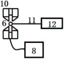
图1为实施例一中步骤1)的元件结构示意图;Fig. 1 is the component structure schematic diagram of step 1) in embodiment one;
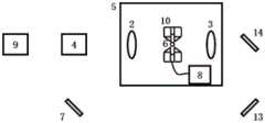
图2为实施例一中步骤3)的元件结构示意图;Fig. 2 is the component structure diagram of step 3) in embodiment one;
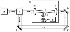
图3为实施例一中步骤3)的元件结构示意图;Fig. 3 is the component structure diagram of step 3) in embodiment one;
图4为实施例一中步骤4)的元件结构示意图。Fig. 4 is a schematic diagram of the element structure in step 4) in the first embodiment.
图1-4中,1、光阱捕获光,2、透镜,3、透镜,4、光功率调节模块,5、真空腔,6、微球,7、反射镜,8、三轴电控位移台,9、光源,10、磁阱,11、光纤,12、压电陶瓷,13、反射镜,14、反射镜。图1-4中各元件尺寸并不代表元件实物尺寸。In Fig. 1-4, 1. Optical trap captures light, 2. Lens, 3. Lens, 4. Optical power adjustment module, 5. Vacuum cavity, 6. Microsphere, 7. Mirror, 8. Three-axis electric control displacement Taiwan, 9, light source, 10, magnetic trap, 11, optical fiber, 12, piezoelectric ceramics, 13, reflector, 14, reflector. The size of each component in Figure 1-4 does not represent the actual size of the component.
具体实施方式Detailed ways
下面结合附图和实施例对本发明作进一步说明。The present invention will be further described below in conjunction with drawings and embodiments.
如图3所示,装置包括:As shown in Figure 3, the device includes:
包含真空腔5,用于在微球6周围环境形成真空环境;Contains a
包括磁阱组件,磁阱组件用于产生磁阱捕获微球6;Including a magnetic trap assembly, the magnetic trap assembly is used to produce magnetic
包括光阱组件,光阱组件用于产生光阱捕获微球6,局部布置于真空腔5;Including an optical trap assembly, the optical trap assembly is used to generate an optical
包括起支组件,用于初始固定并释放微球6。Includes starting assembly for initial immobilization and release of microspheres6.
磁阱组件为可移动的磁阱组件,在磁阱捕获微球6前不布置于真空中,在磁阱捕获微球6后布置于真空中,在光阱捕获微球6后移走。The magnetic trap assembly is a movable magnetic trap assembly, which is not arranged in vacuum before the magnetic trap captures the
磁阱组件包括三轴电控位移台8和磁阱发生器10,三轴电控位移台8和磁阱发生器10连接,由三轴电控位移台8带动磁阱发生器10在空间中三维移动,可以做水平方向的运动。The magnetic trap assembly includes a three-axis
起支组件包括光纤11和压电陶瓷12;光纤11一端粘附微球6,且延伸至磁阱组件产生的磁阱内部,另一端连接压电陶瓷12。The supporting component includes an
如图3和图4所示,光阱组件包括沿同一光轴布置的两个透镜2、3、光功率调节模块4、光源9、反射镜7、13、14;光源9发出光阱捕获光1的光束,光阱捕获光1经光功率调节模块4功率调节后分为两束光,一束光沿原光路前行,另一束光经过反射镜7、13、14,两者分别从真空腔5对称的两侧入射到真空腔5内,经两个透镜2、3汇聚后形成双光束光阱。As shown in Fig. 3 and Fig. 4, the light trap assembly includes two
除光阱组件的透镜2、3、微球6、磁阱组件和起支组件位于真空腔5内,其余元件都位于真空腔5外。Except that the
本发明的实施例及其实施过程如下:Embodiments of the present invention and its implementation process are as follows:
步骤1):step 1):
起支是指将粘附在固态基板上或者悬浮在溶液中的微球转移至势阱并被其捕获的过程。本发明采用振动脱附法方式,能够很好适用于微米级尺寸的微球。如图1所示,光纤末端用酒精擦净后,粘附上微球。光纤下伸至磁阱中间,另一端连接压电陶瓷。压电陶瓷高频率振动,使得微球振动脱离光纤至磁阱内,完成腔内振动起支。Spinning refers to the process of transferring microspheres attached to a solid substrate or suspended in solution to a potential well and captured by it. The present invention adopts a vibration desorption method, which can be well applied to microspheres of micron size. As shown in Figure 1, the end of the optical fiber was wiped clean with alcohol and then adhered with microspheres. The optical fiber extends down to the middle of the magnetic trap, and the other end is connected to the piezoelectric ceramic. The high-frequency vibration of the piezoelectric ceramic makes the vibration of the microsphere break away from the optical fiber and enter the magnetic trap to complete the vibration initiation in the cavity.
步骤2):Step 2):
如图2所示,如果希望实现稳定的悬浮,则设计合理的磁场分布是至关重要的。对于使用永磁体的抗磁悬浮,关键是在磁阱中心处构建处极大磁场梯度。此时磁阱中存在重力势能和磁能的总和势能最低点,即力平衡位置。微球由于空气摩擦力损失动能后逐渐移动到该力平衡位置,实现捕获。待微球捕获、稳定悬浮后,再开始抽高真空。As shown in Figure 2, if you want to achieve stable levitation, designing a reasonable magnetic field distribution is crucial. For diamagnetic levitation using permanent magnets, the key is to create a very large magnetic field gradient at the center of the magnetic trap. At this time, there is the lowest point of the sum potential energy of gravitational potential energy and magnetic energy in the magnetic trap, that is, the position of force balance. After losing kinetic energy due to air friction, the microspheres gradually move to the force balance position to achieve capture. After the microspheres are captured and suspended stably, high vacuum is started.
步骤3):Step 3):
如图3所示,调节光功率调节模块,开启光阱捕获光。采用腔内针孔对准方法可以保证短时间内对射双光束的径向对准误差在微米以内,此时光阱捕获光在真空腔内被聚焦形成光阱。调整磁阱位置,使得微球处于双光束焦点位置,且在光阱、磁阱内稳定悬浮。As shown in Figure 3, the optical power adjustment module is adjusted, and the optical trap is turned on to capture light. The intracavity pinhole alignment method can ensure that the radial alignment error of the two beams facing each other is within microns in a short period of time. At this time, the light captured by the optical trap is focused in the vacuum cavity to form an optical trap. Adjust the position of the magnetic trap so that the microspheres are at the focal point of the double beams and are stably suspended in the optical trap and the magnetic trap.
步骤4):Step 4):
如图4所示,利用三轴电控位移台移动磁阱,使得磁阱远离在光阱中稳定悬浮的微球。根据仿真计算,磁阱离开光阱一厘米以上时可以使得悬浮微球忽略磁阱对其的影响,使得磁阱对微球的力小于光阱对其的力一个量级以上。考虑利用质心运动反馈冷却抑制当磁阱离开时微球的运动,使得微球稳定悬浮在高真空的光阱中。As shown in Figure 4, the magnetic trap is moved by using a three-axis electrically controlled displacement stage so that the magnetic trap is far away from the microspheres stably suspended in the optical trap. According to the simulation calculation, when the magnetic trap is more than one centimeter away from the optical trap, the suspended microsphere can ignore the influence of the magnetic trap on it, so that the force of the magnetic trap on the microsphere is more than an order of magnitude smaller than the force of the optical trap on it. Consider using centroid motion feedback cooling to suppress the motion of the microspheres when the magnetic trap leaves, so that the microspheres are stably suspended in the high-vacuum optical trap.
综上,本发明结合磁阱捕获并悬浮微球至高真空环境、微球由磁阱转移至双光束光阱悬浮微球的方法,保证微球在抽高真空的过程中利用磁阱实现捕获和稳定悬浮,并在抽高真空后在双光束的高刚度光阱中不利用传统的复杂质心运动冷却系统来维持稳定悬浮。上述具体实施方式用来解释说明本发明,而不是对本发明进行限制,在本发明的精神和权利要求的保护范围内,对本发明做出的任何修改和改变,都落入本发明的保护范围。In summary, the present invention combines magnetic traps to capture and suspend microspheres to a high vacuum environment, and the method of transferring microspheres from magnetic traps to double-beam optical traps to suspend microspheres, so as to ensure that microspheres are captured and suspended by magnetic traps during the high vacuum process. Stable suspension, and maintain stable suspension in the double-beam high-rigidity optical trap after high vacuum without using the traditional complex center-of-mass motion cooling system. The specific embodiments above are used to explain the present invention, rather than to limit the present invention. Within the spirit of the present invention and the protection scope of the claims, any modification and change made to the present invention will fall into the protection scope of the present invention.
Claims (6)
Translated fromChinesePriority Applications (1)
| Application Number | Priority Date | Filing Date | Title |
|---|---|---|---|
| CN202210449550.6ACN114910662B (en) | 2022-04-26 | 2022-04-26 | Device and method for realizing high-vacuum environment suspension microsphere by combining magnetic trap and optical trap |
Applications Claiming Priority (1)
| Application Number | Priority Date | Filing Date | Title |
|---|---|---|---|
| CN202210449550.6ACN114910662B (en) | 2022-04-26 | 2022-04-26 | Device and method for realizing high-vacuum environment suspension microsphere by combining magnetic trap and optical trap |
Publications (2)
| Publication Number | Publication Date |
|---|---|
| CN114910662A CN114910662A (en) | 2022-08-16 |
| CN114910662Btrue CN114910662B (en) | 2023-05-23 |
Family
ID=82764122
Family Applications (1)
| Application Number | Title | Priority Date | Filing Date |
|---|---|---|---|
| CN202210449550.6AActiveCN114910662B (en) | 2022-04-26 | 2022-04-26 | Device and method for realizing high-vacuum environment suspension microsphere by combining magnetic trap and optical trap |
Country Status (1)
| Country | Link |
|---|---|
| CN (1) | CN114910662B (en) |
Families Citing this family (5)
| Publication number | Priority date | Publication date | Assignee | Title |
|---|---|---|---|---|
| CN115493726B (en)* | 2022-11-16 | 2023-05-05 | 之江实验室 | Vacuum anti-magnetic levitation force detector and application method thereof |
| CN116449050B (en)* | 2023-04-06 | 2025-07-08 | 浙江大学 | A device and control method for high vacuum on-chip light trap based on superlens |
| CN116417173B (en)* | 2023-06-12 | 2023-08-22 | 之江实验室 | Vacuum optical tweezers system for suspending nano particles |
| CN117111163B (en)* | 2023-08-07 | 2024-08-02 | 之江实验室 | Gravity measuring device |
| CN117074801B (en)* | 2023-10-14 | 2024-02-13 | 之江实验室 | A device and method for measuring electric field using suspended charged microspheres |
Citations (3)
| Publication number | Priority date | Publication date | Assignee | Title |
|---|---|---|---|---|
| CN105759074A (en)* | 2016-03-07 | 2016-07-13 | 浙江大学 | Optical suspension-type microballoon rising and supporting method and device |
| CN105785071A (en)* | 2016-03-07 | 2016-07-20 | 浙江大学 | High-sensitivity light trap measuring device and measuring method thereof |
| CN107607047A (en)* | 2017-09-14 | 2018-01-19 | 中国人民解放军国防科技大学 | A Method of Correcting Axis Misalignment of Image Sensor in Dual Beam Optical Trap |
Family Cites Families (10)
| Publication number | Priority date | Publication date | Assignee | Title |
|---|---|---|---|---|
| JP2005181085A (en)* | 2003-12-19 | 2005-07-07 | Ricoh Co Ltd | Optical trap probe near-field light microscope apparatus and near-field light detection method |
| CN103586126A (en)* | 2013-11-05 | 2014-02-19 | 合肥工业大学 | Magnetic trap for capturing magnetic impurities in high-temperature liquid metal coolant |
| CN104374697B (en)* | 2014-11-10 | 2017-02-15 | 华中科技大学 | Magnetic tweezers and optical tweezers measuring and controlling system |
| CN109192351A (en)* | 2018-09-04 | 2019-01-11 | 中国人民解放军国防科技大学 | A device for efficient loading of microspheres in a double-beam optical trap system |
| CN110596003A (en)* | 2019-09-27 | 2019-12-20 | 武汉铢寸科技有限公司 | Super-resolution microscopic analysis magneto-optical tweezers device |
| CN112735626A (en)* | 2019-10-14 | 2021-04-30 | 华为技术有限公司 | Ion trapping device and ion trapping method |
| CN111999295B (en)* | 2020-08-07 | 2021-06-04 | 浙江大学 | Method and device for repeatedly capturing microspheres in double-beam optical trap |
| CN112485163A (en)* | 2020-11-20 | 2021-03-12 | 浙江大学 | Device and method for feeding back cooling particles in double-beam optical trap |
| CN112466506B (en)* | 2021-01-29 | 2021-04-27 | 之江实验室 | Vacuum optical trap supporting method and device and application |
| CN113257451B (en)* | 2021-05-11 | 2024-04-12 | 中国人民解放军国防科技大学 | Method for stabilizing captured microsphere position in double-beam optical trap |
- 2022
- 2022-04-26CNCN202210449550.6Apatent/CN114910662B/enactiveActive
Patent Citations (3)
| Publication number | Priority date | Publication date | Assignee | Title |
|---|---|---|---|---|
| CN105759074A (en)* | 2016-03-07 | 2016-07-13 | 浙江大学 | Optical suspension-type microballoon rising and supporting method and device |
| CN105785071A (en)* | 2016-03-07 | 2016-07-20 | 浙江大学 | High-sensitivity light trap measuring device and measuring method thereof |
| CN107607047A (en)* | 2017-09-14 | 2018-01-19 | 中国人民解放军国防科技大学 | A Method of Correcting Axis Misalignment of Image Sensor in Dual Beam Optical Trap |
Also Published As
| Publication number | Publication date |
|---|---|
| CN114910662A (en) | 2022-08-16 |
Similar Documents
| Publication | Publication Date | Title |
|---|---|---|
| CN114910662B (en) | Device and method for realizing high-vacuum environment suspension microsphere by combining magnetic trap and optical trap | |
| CN111564233B (en) | Particle repeated supporting experimental device and method for vacuum optical tweezers system | |
| Ranjit et al. | Attonewton force detection using microspheres in a dual-beam optical trap in high vacuum | |
| Friese et al. | Optically driven micromachine elements | |
| CN109814165B (en) | A miniaturized high-precision optical gravimeter with optical cooling | |
| CN112485163A (en) | Device and method for feeding back cooling particles in double-beam optical trap | |
| Schuck et al. | Ultrafast rotation of magnetically levitated macroscopic steel spheres | |
| CN107525946A (en) | Method and device for measuring acceleration based on atomic interference in optical waveguide | |
| CN113568181A (en) | A system and method for directly capturing particles with optical tweezers under high vacuum conditions | |
| CN114624153B (en) | Method and device for measuring radius of trapped particles of optical trap based on echo wall resonance mode | |
| CN103337271B (en) | A kind of Trapping of Atoms of chip surface and Optical Lattices method | |
| CN111986830B (en) | Method and device for lossless, accurate and repeatable capture of microspheres based on evanescent waves | |
| CN116417173B (en) | Vacuum optical tweezers system for suspending nano particles | |
| Higurashi et al. | Optically induced rotation of a trapped micro-object about an axis perpendicular to the laser beam axis | |
| Sokolenko et al. | Optical tweezers and manipulators. Modern concepts and future prospects | |
| Atherton | Sensitive force measurements with optically trapped micro-spheres in high vacuum | |
| CN110097994A (en) | A kind of system and method for repeating to capture microballoon based on pulse laser | |
| CN106935307A (en) | Precise control microballoon based on pulse laser carries out the method and device of light suspension | |
| CN103050166B (en) | Method capable of realizing neutral cold atom laser guidance with nano-scale cross section | |
| CN112967831A (en) | Method and device for repeatedly supporting and suspending microspheres in optical trap | |
| CN1079158C (en) | Optical suspension measuring system | |
| RU182549U1 (en) | Subwavelength optical trap in the field of a standing wave based on a photon jet | |
| JP3053183B1 (en) | Floating melting using pseudo-microgravity field by magnetic force | |
| RU160834U1 (en) | SUBWAVE OPTICAL TRAP IN THE STANDING WAVE FIELD | |
| CN111986831B (en) | Totally enclosed wafer type optical trap device for repeatedly capturing microspheres by evanescent waves |
Legal Events
| Date | Code | Title | Description |
|---|---|---|---|
| PB01 | Publication | ||
| PB01 | Publication | ||
| SE01 | Entry into force of request for substantive examination | ||
| SE01 | Entry into force of request for substantive examination | ||
| GR01 | Patent grant | ||
| GR01 | Patent grant |