CN114903657A - Prosthetic heart valve devices, prosthetic mitral valves, and related systems and methods - Google Patents
Prosthetic heart valve devices, prosthetic mitral valves, and related systems and methodsDownload PDFInfo
- Publication number
- CN114903657A CN114903657ACN202210596539.2ACN202210596539ACN114903657ACN 114903657 ACN114903657 ACN 114903657ACN 202210596539 ACN202210596539 ACN 202210596539ACN 114903657 ACN114903657 ACN 114903657A
- Authority
- CN
- China
- Prior art keywords
- valve
- anchoring member
- tissue
- annulus
- valve support
- Prior art date
- Legal status (The legal status is an assumption and is not a legal conclusion. Google has not performed a legal analysis and makes no representation as to the accuracy of the status listed.)
- Granted
Links
Images


Classifications
- A—HUMAN NECESSITIES
- A61—MEDICAL OR VETERINARY SCIENCE; HYGIENE
- A61F—FILTERS IMPLANTABLE INTO BLOOD VESSELS; PROSTHESES; DEVICES PROVIDING PATENCY TO, OR PREVENTING COLLAPSING OF, TUBULAR STRUCTURES OF THE BODY, e.g. STENTS; ORTHOPAEDIC, NURSING OR CONTRACEPTIVE DEVICES; FOMENTATION; TREATMENT OR PROTECTION OF EYES OR EARS; BANDAGES, DRESSINGS OR ABSORBENT PADS; FIRST-AID KITS
- A61F2/00—Filters implantable into blood vessels; Prostheses, i.e. artificial substitutes or replacements for parts of the body; Appliances for connecting them with the body; Devices providing patency to, or preventing collapsing of, tubular structures of the body, e.g. stents
- A61F2/02—Prostheses implantable into the body
- A61F2/24—Heart valves ; Vascular valves, e.g. venous valves; Heart implants, e.g. passive devices for improving the function of the native valve or the heart muscle; Transmyocardial revascularisation [TMR] devices; Valves implantable in the body
- A61F2/2412—Heart valves ; Vascular valves, e.g. venous valves; Heart implants, e.g. passive devices for improving the function of the native valve or the heart muscle; Transmyocardial revascularisation [TMR] devices; Valves implantable in the body with soft flexible valve members, e.g. tissue valves shaped like natural valves
- A61F2/2418—Scaffolds therefor, e.g. support stents
- A—HUMAN NECESSITIES
- A61—MEDICAL OR VETERINARY SCIENCE; HYGIENE
- A61F—FILTERS IMPLANTABLE INTO BLOOD VESSELS; PROSTHESES; DEVICES PROVIDING PATENCY TO, OR PREVENTING COLLAPSING OF, TUBULAR STRUCTURES OF THE BODY, e.g. STENTS; ORTHOPAEDIC, NURSING OR CONTRACEPTIVE DEVICES; FOMENTATION; TREATMENT OR PROTECTION OF EYES OR EARS; BANDAGES, DRESSINGS OR ABSORBENT PADS; FIRST-AID KITS
- A61F2/00—Filters implantable into blood vessels; Prostheses, i.e. artificial substitutes or replacements for parts of the body; Appliances for connecting them with the body; Devices providing patency to, or preventing collapsing of, tubular structures of the body, e.g. stents
- A61F2/02—Prostheses implantable into the body
- A61F2/24—Heart valves ; Vascular valves, e.g. venous valves; Heart implants, e.g. passive devices for improving the function of the native valve or the heart muscle; Transmyocardial revascularisation [TMR] devices; Valves implantable in the body
- A61F2/2427—Devices for manipulating or deploying heart valves during implantation
- A61F2/2436—Deployment by retracting a sheath
- A—HUMAN NECESSITIES
- A61—MEDICAL OR VETERINARY SCIENCE; HYGIENE
- A61F—FILTERS IMPLANTABLE INTO BLOOD VESSELS; PROSTHESES; DEVICES PROVIDING PATENCY TO, OR PREVENTING COLLAPSING OF, TUBULAR STRUCTURES OF THE BODY, e.g. STENTS; ORTHOPAEDIC, NURSING OR CONTRACEPTIVE DEVICES; FOMENTATION; TREATMENT OR PROTECTION OF EYES OR EARS; BANDAGES, DRESSINGS OR ABSORBENT PADS; FIRST-AID KITS
- A61F2/00—Filters implantable into blood vessels; Prostheses, i.e. artificial substitutes or replacements for parts of the body; Appliances for connecting them with the body; Devices providing patency to, or preventing collapsing of, tubular structures of the body, e.g. stents
- A61F2/02—Prostheses implantable into the body
- A61F2/24—Heart valves ; Vascular valves, e.g. venous valves; Heart implants, e.g. passive devices for improving the function of the native valve or the heart muscle; Transmyocardial revascularisation [TMR] devices; Valves implantable in the body
- A61F2/2442—Annuloplasty rings or inserts for correcting the valve shape; Implants for improving the function of a native heart valve
- A61F2/2445—Annuloplasty rings in direct contact with the valve annulus
- A—HUMAN NECESSITIES
- A61—MEDICAL OR VETERINARY SCIENCE; HYGIENE
- A61F—FILTERS IMPLANTABLE INTO BLOOD VESSELS; PROSTHESES; DEVICES PROVIDING PATENCY TO, OR PREVENTING COLLAPSING OF, TUBULAR STRUCTURES OF THE BODY, e.g. STENTS; ORTHOPAEDIC, NURSING OR CONTRACEPTIVE DEVICES; FOMENTATION; TREATMENT OR PROTECTION OF EYES OR EARS; BANDAGES, DRESSINGS OR ABSORBENT PADS; FIRST-AID KITS
- A61F2/00—Filters implantable into blood vessels; Prostheses, i.e. artificial substitutes or replacements for parts of the body; Appliances for connecting them with the body; Devices providing patency to, or preventing collapsing of, tubular structures of the body, e.g. stents
- A61F2/02—Prostheses implantable into the body
- A61F2/24—Heart valves ; Vascular valves, e.g. venous valves; Heart implants, e.g. passive devices for improving the function of the native valve or the heart muscle; Transmyocardial revascularisation [TMR] devices; Valves implantable in the body
- A61F2/2442—Annuloplasty rings or inserts for correcting the valve shape; Implants for improving the function of a native heart valve
- A61F2/246—Devices for obstructing a leak through a native valve in a closed condition
- A—HUMAN NECESSITIES
- A61—MEDICAL OR VETERINARY SCIENCE; HYGIENE
- A61F—FILTERS IMPLANTABLE INTO BLOOD VESSELS; PROSTHESES; DEVICES PROVIDING PATENCY TO, OR PREVENTING COLLAPSING OF, TUBULAR STRUCTURES OF THE BODY, e.g. STENTS; ORTHOPAEDIC, NURSING OR CONTRACEPTIVE DEVICES; FOMENTATION; TREATMENT OR PROTECTION OF EYES OR EARS; BANDAGES, DRESSINGS OR ABSORBENT PADS; FIRST-AID KITS
- A61F2/00—Filters implantable into blood vessels; Prostheses, i.e. artificial substitutes or replacements for parts of the body; Appliances for connecting them with the body; Devices providing patency to, or preventing collapsing of, tubular structures of the body, e.g. stents
- A61F2/02—Prostheses implantable into the body
- A61F2/24—Heart valves ; Vascular valves, e.g. venous valves; Heart implants, e.g. passive devices for improving the function of the native valve or the heart muscle; Transmyocardial revascularisation [TMR] devices; Valves implantable in the body
- A61F2/2409—Support rings therefor, e.g. for connecting valves to tissue
- A—HUMAN NECESSITIES
- A61—MEDICAL OR VETERINARY SCIENCE; HYGIENE
- A61F—FILTERS IMPLANTABLE INTO BLOOD VESSELS; PROSTHESES; DEVICES PROVIDING PATENCY TO, OR PREVENTING COLLAPSING OF, TUBULAR STRUCTURES OF THE BODY, e.g. STENTS; ORTHOPAEDIC, NURSING OR CONTRACEPTIVE DEVICES; FOMENTATION; TREATMENT OR PROTECTION OF EYES OR EARS; BANDAGES, DRESSINGS OR ABSORBENT PADS; FIRST-AID KITS
- A61F2220/00—Fixations or connections for prostheses classified in groups A61F2/00 - A61F2/26 or A61F2/82 or A61F9/00 or A61F11/00 or subgroups thereof
- A61F2220/0008—Fixation appliances for connecting prostheses to the body
- A61F2220/0016—Fixation appliances for connecting prostheses to the body with sharp anchoring protrusions, e.g. barbs, pins, spikes
- A—HUMAN NECESSITIES
- A61—MEDICAL OR VETERINARY SCIENCE; HYGIENE
- A61F—FILTERS IMPLANTABLE INTO BLOOD VESSELS; PROSTHESES; DEVICES PROVIDING PATENCY TO, OR PREVENTING COLLAPSING OF, TUBULAR STRUCTURES OF THE BODY, e.g. STENTS; ORTHOPAEDIC, NURSING OR CONTRACEPTIVE DEVICES; FOMENTATION; TREATMENT OR PROTECTION OF EYES OR EARS; BANDAGES, DRESSINGS OR ABSORBENT PADS; FIRST-AID KITS
- A61F2220/00—Fixations or connections for prostheses classified in groups A61F2/00 - A61F2/26 or A61F2/82 or A61F9/00 or A61F11/00 or subgroups thereof
- A61F2220/0025—Connections or couplings between prosthetic parts, e.g. between modular parts; Connecting elements
- A61F2220/0041—Connections or couplings between prosthetic parts, e.g. between modular parts; Connecting elements using additional screws, bolts, dowels or rivets, e.g. connecting screws
- A—HUMAN NECESSITIES
- A61—MEDICAL OR VETERINARY SCIENCE; HYGIENE
- A61F—FILTERS IMPLANTABLE INTO BLOOD VESSELS; PROSTHESES; DEVICES PROVIDING PATENCY TO, OR PREVENTING COLLAPSING OF, TUBULAR STRUCTURES OF THE BODY, e.g. STENTS; ORTHOPAEDIC, NURSING OR CONTRACEPTIVE DEVICES; FOMENTATION; TREATMENT OR PROTECTION OF EYES OR EARS; BANDAGES, DRESSINGS OR ABSORBENT PADS; FIRST-AID KITS
- A61F2220/00—Fixations or connections for prostheses classified in groups A61F2/00 - A61F2/26 or A61F2/82 or A61F9/00 or A61F11/00 or subgroups thereof
- A61F2220/0025—Connections or couplings between prosthetic parts, e.g. between modular parts; Connecting elements
- A61F2220/005—Connections or couplings between prosthetic parts, e.g. between modular parts; Connecting elements using adhesives
- A—HUMAN NECESSITIES
- A61—MEDICAL OR VETERINARY SCIENCE; HYGIENE
- A61F—FILTERS IMPLANTABLE INTO BLOOD VESSELS; PROSTHESES; DEVICES PROVIDING PATENCY TO, OR PREVENTING COLLAPSING OF, TUBULAR STRUCTURES OF THE BODY, e.g. STENTS; ORTHOPAEDIC, NURSING OR CONTRACEPTIVE DEVICES; FOMENTATION; TREATMENT OR PROTECTION OF EYES OR EARS; BANDAGES, DRESSINGS OR ABSORBENT PADS; FIRST-AID KITS
- A61F2220/00—Fixations or connections for prostheses classified in groups A61F2/00 - A61F2/26 or A61F2/82 or A61F9/00 or A61F11/00 or subgroups thereof
- A61F2220/0025—Connections or couplings between prosthetic parts, e.g. between modular parts; Connecting elements
- A61F2220/0066—Connections or couplings between prosthetic parts, e.g. between modular parts; Connecting elements stapled
- A—HUMAN NECESSITIES
- A61—MEDICAL OR VETERINARY SCIENCE; HYGIENE
- A61F—FILTERS IMPLANTABLE INTO BLOOD VESSELS; PROSTHESES; DEVICES PROVIDING PATENCY TO, OR PREVENTING COLLAPSING OF, TUBULAR STRUCTURES OF THE BODY, e.g. STENTS; ORTHOPAEDIC, NURSING OR CONTRACEPTIVE DEVICES; FOMENTATION; TREATMENT OR PROTECTION OF EYES OR EARS; BANDAGES, DRESSINGS OR ABSORBENT PADS; FIRST-AID KITS
- A61F2220/00—Fixations or connections for prostheses classified in groups A61F2/00 - A61F2/26 or A61F2/82 or A61F9/00 or A61F11/00 or subgroups thereof
- A61F2220/0025—Connections or couplings between prosthetic parts, e.g. between modular parts; Connecting elements
- A61F2220/0075—Connections or couplings between prosthetic parts, e.g. between modular parts; Connecting elements sutured, ligatured or stitched, retained or tied with a rope, string, thread, wire or cable
- A—HUMAN NECESSITIES
- A61—MEDICAL OR VETERINARY SCIENCE; HYGIENE
- A61F—FILTERS IMPLANTABLE INTO BLOOD VESSELS; PROSTHESES; DEVICES PROVIDING PATENCY TO, OR PREVENTING COLLAPSING OF, TUBULAR STRUCTURES OF THE BODY, e.g. STENTS; ORTHOPAEDIC, NURSING OR CONTRACEPTIVE DEVICES; FOMENTATION; TREATMENT OR PROTECTION OF EYES OR EARS; BANDAGES, DRESSINGS OR ABSORBENT PADS; FIRST-AID KITS
- A61F2230/00—Geometry of prostheses classified in groups A61F2/00 - A61F2/26 or A61F2/82 or A61F9/00 or A61F11/00 or subgroups thereof
- A61F2230/0002—Two-dimensional shapes, e.g. cross-sections
- A61F2230/0028—Shapes in the form of latin or greek characters
- A61F2230/0054—V-shaped
- A—HUMAN NECESSITIES
- A61—MEDICAL OR VETERINARY SCIENCE; HYGIENE
- A61F—FILTERS IMPLANTABLE INTO BLOOD VESSELS; PROSTHESES; DEVICES PROVIDING PATENCY TO, OR PREVENTING COLLAPSING OF, TUBULAR STRUCTURES OF THE BODY, e.g. STENTS; ORTHOPAEDIC, NURSING OR CONTRACEPTIVE DEVICES; FOMENTATION; TREATMENT OR PROTECTION OF EYES OR EARS; BANDAGES, DRESSINGS OR ABSORBENT PADS; FIRST-AID KITS
- A61F2230/00—Geometry of prostheses classified in groups A61F2/00 - A61F2/26 or A61F2/82 or A61F9/00 or A61F11/00 or subgroups thereof
- A61F2230/0063—Three-dimensional shapes
- A61F2230/0067—Three-dimensional shapes conical
- A—HUMAN NECESSITIES
- A61—MEDICAL OR VETERINARY SCIENCE; HYGIENE
- A61F—FILTERS IMPLANTABLE INTO BLOOD VESSELS; PROSTHESES; DEVICES PROVIDING PATENCY TO, OR PREVENTING COLLAPSING OF, TUBULAR STRUCTURES OF THE BODY, e.g. STENTS; ORTHOPAEDIC, NURSING OR CONTRACEPTIVE DEVICES; FOMENTATION; TREATMENT OR PROTECTION OF EYES OR EARS; BANDAGES, DRESSINGS OR ABSORBENT PADS; FIRST-AID KITS
- A61F2230/00—Geometry of prostheses classified in groups A61F2/00 - A61F2/26 or A61F2/82 or A61F9/00 or A61F11/00 or subgroups thereof
- A61F2230/0063—Three-dimensional shapes
- A61F2230/0069—Three-dimensional shapes cylindrical
- A—HUMAN NECESSITIES
- A61—MEDICAL OR VETERINARY SCIENCE; HYGIENE
- A61F—FILTERS IMPLANTABLE INTO BLOOD VESSELS; PROSTHESES; DEVICES PROVIDING PATENCY TO, OR PREVENTING COLLAPSING OF, TUBULAR STRUCTURES OF THE BODY, e.g. STENTS; ORTHOPAEDIC, NURSING OR CONTRACEPTIVE DEVICES; FOMENTATION; TREATMENT OR PROTECTION OF EYES OR EARS; BANDAGES, DRESSINGS OR ABSORBENT PADS; FIRST-AID KITS
- A61F2230/00—Geometry of prostheses classified in groups A61F2/00 - A61F2/26 or A61F2/82 or A61F9/00 or A61F11/00 or subgroups thereof
- A61F2230/0063—Three-dimensional shapes
- A61F2230/0073—Quadric-shaped
- A61F2230/0078—Quadric-shaped hyperboloidal
- A—HUMAN NECESSITIES
- A61—MEDICAL OR VETERINARY SCIENCE; HYGIENE
- A61F—FILTERS IMPLANTABLE INTO BLOOD VESSELS; PROSTHESES; DEVICES PROVIDING PATENCY TO, OR PREVENTING COLLAPSING OF, TUBULAR STRUCTURES OF THE BODY, e.g. STENTS; ORTHOPAEDIC, NURSING OR CONTRACEPTIVE DEVICES; FOMENTATION; TREATMENT OR PROTECTION OF EYES OR EARS; BANDAGES, DRESSINGS OR ABSORBENT PADS; FIRST-AID KITS
- A61F2250/00—Special features of prostheses classified in groups A61F2/00 - A61F2/26 or A61F2/82 or A61F9/00 or A61F11/00 or subgroups thereof
- A61F2250/0058—Additional features; Implant or prostheses properties not otherwise provided for
- A61F2250/006—Additional features; Implant or prostheses properties not otherwise provided for modular
- A—HUMAN NECESSITIES
- A61—MEDICAL OR VETERINARY SCIENCE; HYGIENE
- A61F—FILTERS IMPLANTABLE INTO BLOOD VESSELS; PROSTHESES; DEVICES PROVIDING PATENCY TO, OR PREVENTING COLLAPSING OF, TUBULAR STRUCTURES OF THE BODY, e.g. STENTS; ORTHOPAEDIC, NURSING OR CONTRACEPTIVE DEVICES; FOMENTATION; TREATMENT OR PROTECTION OF EYES OR EARS; BANDAGES, DRESSINGS OR ABSORBENT PADS; FIRST-AID KITS
- A61F2250/00—Special features of prostheses classified in groups A61F2/00 - A61F2/26 or A61F2/82 or A61F9/00 or A61F11/00 or subgroups thereof
- A61F2250/0058—Additional features; Implant or prostheses properties not otherwise provided for
- A61F2250/0069—Sealing means
Landscapes
- Health & Medical Sciences (AREA)
- Cardiology (AREA)
- Engineering & Computer Science (AREA)
- Biomedical Technology (AREA)
- Heart & Thoracic Surgery (AREA)
- Transplantation (AREA)
- Oral & Maxillofacial Surgery (AREA)
- Vascular Medicine (AREA)
- Life Sciences & Earth Sciences (AREA)
- Animal Behavior & Ethology (AREA)
- General Health & Medical Sciences (AREA)
- Public Health (AREA)
- Veterinary Medicine (AREA)
- Prostheses (AREA)
Abstract
Translated fromChinese
Description
Translated fromChinese本申请是申请号为201910994619.1的中国发明专利申请的分案申请。该申请是第201610916761.0号中国发明专利申请的分案申请,该中国发明专利申请申请日为2012年10月19日,发明名称为“人工心脏瓣膜装置、人工二尖瓣和相关系统及方法”。This application is a divisional application of the Chinese invention patent application with the application number of 201910994619.1. This application is a divisional application of Chinese Invention Patent Application No. 201610916761.0, which was filed on October 19, 2012, and the name of the invention is "Prosthetic Heart Valve Device, Prosthetic Mitral Valve and Related Systems and Methods".
相关申请的交叉引用CROSS-REFERENCE TO RELATED APPLICATIONS
本申请对2012年3月1日提交的名为“SYSTEM FOR MITRAL VALVE REPLACEMENT(用于二尖瓣置换的系统)”的美国临时专利申请号 61/605,699、对2011年10月19日提交的名为“CONFORMABLE SYSTEM FOR MITRAL VALVE REPLACEMENT(用于二尖瓣替换的适形系统)”的美国临时专利申请号61/549,044要求优先权,所述两篇文献均通过引用的方式完整结合在此。本申请通过引用的方式完整结合(1)2012年6月21日提交的名为“PROSTHETICHEARTVALVE DEVICES AND ASSOCIATED SYSTEMS AND METHODS(人工心脏瓣膜装置和相关系统及方法)”的国际 PCT专利号申请号PCT/US2012/043636;(2)2011年10月19日提交的名为“SYSTEM FOR MITRAL VALVE REPLACEMENT(用于二尖瓣替换的系统)”的美国临时专利申请号61/549,037;和(3)2012年10月19日提交的名为“Devices,SYSTEMs and methodsforheart valve REPLACEMENT(用于心脏瓣膜替换术的装置、系统和方法)”的国际PCT专利号申请号 WO2013/059743(代理人案号82829-8005WO00)。This application complies with U.S. Provisional Patent Application No. 61/605,699, filed March 1, 2012, entitled "SYSTEM FOR MITRAL VALVE REPLACEMENT," and filed on October 19, 2011. Priority is claimed to US Provisional Patent Application No. 61/549,044 for "CONFORMABLE SYSTEM FOR MITRAL VALVE REPLACEMENT", both of which are incorporated herein by reference in their entirety. This application incorporates by reference in its entirety (1) International PCT Patent Application No. PCT/ US2012/043636; (2) US Provisional Patent Application No. 61/549,037, filed October 19, 2011, titled "SYSTEM FOR MITRAL VALVE REPLACEMENT"; and (3) 2012 International PCT Patent Application No. WO2013/059743 (Attorney Docket No. 82829-8005WO00), filed on October 19, entitled "Devices, SYSTEMs and methods for heart valve REPLACEMENT (devices, systems and methods for heart valve replacement)" .
技术领域technical field
本发明的技术大体上涉及人工心脏瓣膜装置。具体而言,几个实施例涉及用于透皮修复和/或替换天然二尖瓣的人工二尖瓣和装置及相关系统和方法。The present technology generally relates to prosthetic heart valve devices. In particular, several embodiments relate to prosthetic mitral valves and devices and related systems and methods for transdermal repair and/or replacement of native mitral valves.
背景技术Background technique
影响二尖瓣正常功能的疾病例如包括二尖瓣反流、二尖瓣脱垂和二尖瓣狭窄。二尖瓣反流是心脏疾病其中二尖瓣的瓣叶不能在峰收缩压闭合成对合,导致血液从左心室异常泄漏至左心房中。存在许多可能影响二尖瓣正确闭合的结构性因素。例如,许多患有心脏病的患者经历心肌的扩张,导致放大的二尖瓣膜环。二尖瓣膜环的膨大导致瓣叶难以在心脏收缩期期间闭合。腱索中拉伸或撕裂(腱使乳头肌连接至二尖瓣叶内侧)也可能影响二尖瓣膜环正确闭合。例如,破裂的腱索可能造成瓣叶脱垂入左心房,原因在于瓣叶上的张力不足。当乳头肌的功能例如因局部缺血受损时,异常回流也可能出现。随着左心室在心脏收缩期期间收缩,受累的乳头肌并未充分地收缩以实现正确闭合。Diseases that affect the normal function of the mitral valve include, for example, mitral regurgitation, mitral valve prolapse, and mitral valve stenosis. Mitral regurgitation is a heart disease in which the leaflets of the mitral valve fail to close into apposition at peak systolic pressure, resulting in abnormal leakage of blood from the left ventricle into the left atrium. There are many structural factors that may affect the proper closure of the mitral valve. For example, many patients with heart disease experience dilation of the heart muscle, resulting in an enlarged mitral valve annulus. The enlargement of the mitral valve annulus makes it difficult for the valve leaflets to close during systole. A stretch or tear in the chordae tendineae (the tendons that connect the papillary muscles to the inside of the mitral valve leaflets) may also prevent the mitral annulus from closing properly. For example, ruptured chordae tendineae may cause leaflets to prolapse into the left atrium due to insufficient tension on the leaflets. Abnormal reflux may also occur when the function of the papillary muscles is impaired, eg, by ischemia. As the left ventricle contracts during systole, the involved papillary muscles do not contract enough to achieve proper closure.
二尖瓣脱垂或当二尖瓣叶异常凸入左心房时,造成二尖瓣的不规则行为并且也可能导致二尖瓣反流。二尖瓣正常发挥作用也可能受二尖瓣狭窄或二尖瓣口狭窄影响,这造成阻碍左心室在舒张期时充盈。Mitral valve prolapse, or when the mitral valve leaflets protrude abnormally into the left atrium, causes irregular behavior of the mitral valve and may also lead to mitral regurgitation. The normal functioning of the mitral valve may also be affected by mitral stenosis, or mitral orifice stenosis, which prevents the left ventricle from filling during diastole.
一般而言,治疗二尖瓣反流涉及应用利尿药和/或血管舒张药以便减少血液回流入左心房的量。其他方法已经涉及用于修复或替换瓣膜的(开放和血管内)手术方案。例如,常见修复方法涉及收紧或切除部分的扩张瓣膜环。In general, treating mitral regurgitation involves the use of diuretics and/or vasodilators in order to reduce the amount of blood flowing back into the left atrium. Other approaches have involved (open and endovascular) surgical protocols for valve repair or replacement. For example, common repair methods involve tightening or excising portions of the dilated valve annulus.
已经通过植入通常被固定至瓣膜环或周围组织的瓣膜环圈 (annular ring)或围瓣膜环圈(peri-annular ring),完成瓣膜环收紧。其他修复手术还涉及将瓣叶缝合或修剪成彼此局部对合。Annular tightening has been accomplished by implanting an annular or peri-annular ring, which is usually secured to the annulus or surrounding tissue. Other repair procedures also involve suturing or trimming the leaflets into partial alignment with each other.
可替代地,更侵入性的手术涉及替换整个瓣膜本身,其中将机械瓣膜或生物组织植入心脏中替代二尖瓣。这些侵入性手术常规地通过大的开放性开胸术进行并且因此非常疼痛,具有明显的发病率,以及需要漫长的恢复期。Alternatively, a more invasive procedure involves replacing the entire valve itself, where a mechanical valve or biological tissue is implanted in the heart to replace the mitral valve. These invasive procedures are routinely performed by large open thoracotomy and are therefore very painful, have significant morbidity, and require a lengthy recovery period.
但是,采用许多修复和替换手术的情况下,装置的耐久性或瓣膜环成形术环或替换瓣膜的不正确尺寸设定可以对患者造成另外的问题。另外,许多修复手术高度依赖于心外科医生的技巧,其中不良或不精确放置的缝线可能影响手术成功。However, with many repair and replacement procedures, the durability of the device or incorrect sizing of the annuloplasty ring or replacement valve can cause additional problems for the patient. Additionally, many revision surgeries are highly dependent on the skill of the cardiac surgeon, where poorly or inaccurately placed sutures can affect the success of the surgery.
近年来已经开发了针对主动脉瓣膜替换的侵入性较小的方法。预装配的透皮人工瓣膜的例子例如包括来自Medtronic/Corevalve Inc.的CoreValve

与主动脉瓣替换相比,二尖瓣替换术设置了独特的解剖障碍,使得透皮二尖瓣替换比主动脉瓣替换明显更有挑战性。首先,不同于相对对称和均匀的主动脉瓣,二尖瓣膜环具有非圆D形状或肾样形状,非平面的马鞍样几何形状经常缺少对称性。这种不可预测性造成难以设计具有贴合二尖瓣膜环能力的二尖瓣假体。假体和天然瓣叶和/或瓣膜环之间缺少滑配合可能在其中留下间隙,导致血液经这些间隙回流。例如,安置圆柱状瓣膜假体可能在天然瓣膜的连合区中留下间隙,可能导致这些区域内的瓣周泄漏。Compared with aortic valve replacement, mitral valve replacement sets unique anatomical barriers that make transcutaneous mitral valve replacement significantly more challenging than aortic valve replacement. First, unlike the relatively symmetrical and homogeneous aortic valve, the mitral valve annulus has a non-circular D-shape or kidney-like shape, and the non-planar saddle-like geometry often lacks symmetry. This unpredictability makes it difficult to design a mitral valve prosthesis with the ability to conform to the mitral valve annulus. The lack of a snug fit between the prosthesis and the native leaflets and/or valve annulus may leave gaps therein, resulting in backflow of blood through these gaps. For example, placement of a cylindrical valve prosthesis may leave gaps in the commissural regions of the native valve, potentially leading to paravalvular leaks in these regions.
为透皮主动脉瓣替换所开发的当前人工瓣膜不适合改造用于二尖瓣。首先,这些装置中许多需要接触瓣膜环和/或瓣叶的装置结构和支撑人工瓣膜的装置结构之间的直接结构性连接。在几种装置中,支撑人工瓣膜的相同支架立柱还接触瓣膜环或其他周围组织,从而随着心脏在每个心动周期期间收缩而向装置直接转移由组织和血液产生的许多扭曲力。大部分心脏替换装置进一步利用三叶瓣膜,该三叶瓣膜需要围绕人工瓣膜的大体上对称的圆柱状支撑件用于三个瓣叶在寿命年限范围内正确开启和闭合。如果这些装置遭受来自瓣膜环和其他周围组织的移动和力,则假体可能被压缩和/或扭曲,造成假体瓣叶功能异常。另外,常见的患病二尖瓣膜环比任何可获得的人工瓣膜大得多。Current prosthetic valves developed for transcutaneous aortic valve replacement are not suitable for retrofitting in mitral valves. First, many of these devices require a direct structural connection between the device structures that contact the annulus and/or the valve leaflets and the device structures that support the prosthetic valve. In several devices, the same stent posts that support the prosthetic valve also contact the valve annulus or other surrounding tissue, transferring many of the twisting forces generated by tissue and blood directly to the device as the heart contracts during each cardiac cycle. Most heart replacement devices further utilize a tri-leaflet valve, which requires a generally symmetrical cylindrical support around the prosthetic valve for the three leaflets to open and close properly over the life span. If these devices are subjected to movement and forces from the valve annulus and other surrounding tissue, the prosthesis may be compressed and/or distorted, causing the prosthetic leaflets to malfunction. Additionally, the commonly affected mitral valve annulus is much larger than any available prosthetic valve.
除其不规则、不可预测形状之外,二尖瓣膜环缺少来自周围组织的显著量的径向支撑。例如,主动脉瓣被纤维弹性组织完全包围,这有助于通过提供天然结构性支撑固定人工瓣膜。在另一方面,二尖瓣仅由肌肉组织束缚在外壁上。二尖瓣内壁由薄血管壁束缚,该薄血管壁将二尖瓣膜环与主动脉流出道的内在部分分隔。因此,在二尖瓣膜环上的显著径向力,如由扩张性支架假体所赋予的力,可能导致主动脉流出道的内在部分塌陷,伴随潜在致命的后果。In addition to its irregular, unpredictable shape, the mitral valve annulus lacks a significant amount of radial support from surrounding tissue. For example, the aortic valve is completely surrounded by fibroelastic tissue, which helps secure the prosthetic valve by providing natural structural support. On the other hand, the mitral valve is bound to the outer wall only by muscle tissue. The inner wall of the mitral valve is bound by a thin vessel wall that separates the mitral valve annulus from the inner portion of the aortic outflow tract. Thus, significant radial forces on the mitral valve annulus, such as those imparted by an expandable stent-prosthesis, may cause the inner portion of the aortic outflow tract to collapse, with potentially fatal consequences.
左心室的腱索也可能在展开二尖瓣假体时带来障碍。这是二尖瓣独有的,因为主动脉瓣解剖学不包含腱索。左心室中的复杂腱索使得在二尖瓣替换和修复时导航及定位展开导管困难得多。在天然二尖瓣的心室侧面上展开和定位人工瓣膜或锚定装置因腱索的存在进一步复杂化。The chordae tendineae of the left ventricle may also present a barrier to deployment of the mitral valve prosthesis. This is unique to the mitral valve, as the aortic valve anatomy does not contain chordae tendineae. The complex chordae tendineae in the left ventricle make it much more difficult to navigate and position the deployment catheter during mitral valve replacement and repair. Deployment and positioning of the prosthetic valve or anchoring device on the ventricular side of the native mitral valve is further complicated by the presence of chordae tendineae.
鉴于与当前方法相关的难题,仍需要用于治疗机能不良的心脏瓣膜的简单、有效和侵入性低的装置和方法。Given the challenges associated with current methods, there remains a need for simple, effective, and less invasive devices and methods for treating dysfunctional heart valves.
附图简述Brief Description of Drawings
可以参考以下附图更好地理解本披露的许多方面。附图中的组件不必然成比例。相反,重点在于清晰说明本披露的原理。另外,组件可以仅就图示清晰性而言被显示为透明并且不意在表明所示组件是必然透明的。Many aspects of the present disclosure can be better understood with reference to the following drawings. Components in the drawings are not necessarily to scale. Rather, emphasis is placed upon clearly illustrating the principles of the present disclosure. Additionally, components may be shown transparent only for clarity of illustration and are not intended to suggest that components shown are necessarily transparent.
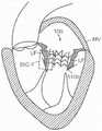
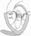
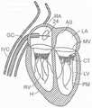
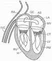
图1和图2是哺乳动物心脏的示意图,该哺乳动物心脏具有适于用根据本技术的实施例的多种人工心脏瓣膜装置替换的天然瓣膜结构。1 and 2 are schematic diagrams of a mammalian heart having a native valve structure suitable for replacement with various prosthetic heart valve devices according to embodiments of the present technology.
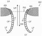
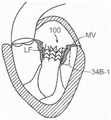
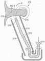
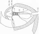
图3是显示瓣膜环和瓣叶的天然二尖瓣示意性截面侧视图。3 is a schematic cross-sectional side view of a native mitral valve showing the valve annulus and valve leaflets.
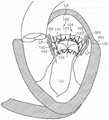
图4A是心脏的左心室的示意图,该心脏具有:i)在二尖瓣中的脱垂瓣叶,或ii)在具有受损乳头肌的心脏的左心室中的二尖瓣反流,并且适用于与根据本技术的实施例的多种人工心脏瓣膜装置组合。4A is a schematic diagram of the left ventricle of a heart with: i) prolapsed leaflets in the mitral valve, or ii) mitral regurgitation in the left ventricle of a heart with damaged papillary muscles, and Suitable for use in combination with various prosthetic heart valve devices according to embodiments of the present technology.
图4B是在心肌病患者中并且适用于与根据本技术的实施例的多种人工心脏瓣膜装置组合的心脏的示意图。4B is a schematic illustration of a heart in a cardiomyopathy patient and suitable for use in combination with various prosthetic heart valve devices according to embodiments of the present technology.
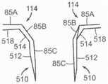
图5A是显示天然二尖瓣瓣叶正常闭合的心脏天然二尖瓣的示意图。Figure 5A is a schematic illustration of the native mitral valve of the heart showing the normal closure of the native mitral valve leaflets.
图5B是心脏天然二尖瓣的示意图,其显示天然二尖瓣瓣叶在扩张的心脏中的异常闭合并且适用于与根据本技术的实施例的多种人工心脏瓣膜装置组合。5B is a schematic illustration of the native mitral valve of the heart showing abnormal closure of the native mitral valve leaflets in a dilated heart and suitable for use in combination with various prosthetic heart valve devices according to embodiments of the present technology.
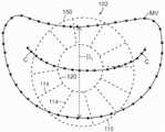
图5C是心脏二尖瓣的示意图,其显示瓣膜环的尺度并且适用于与根据本技术的实施例的多种人工心脏瓣膜装置组合。5C is a schematic diagram of a heart mitral valve showing dimensions of the valve annulus and suitable for use in combination with various prosthetic heart valve devices in accordance with embodiments of the present technology.
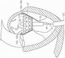
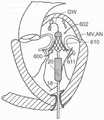
图6A是心脏的示意性截面图,其显示根据本技术的多种实施例从静脉脉管系统至天然二尖瓣的顺行入路。6A is a schematic cross-sectional view of a heart showing an antegrade approach from the venous vasculature to the native mitral valve in accordance with various embodiments of the present technology.
图6B是心脏的示意性截面图,其显示根据本技术的多种实施例,通过在导丝上放置导引导管维持的穿过房中隔(IAS)的通路。6B is a schematic cross-sectional view of a heart showing access through the atrial septum (IAS) maintained by placement of a guide catheter over a guide wire in accordance with various embodiments of the present technology.
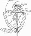
图7和图8是心脏的示意性截面图,其显示根据本技术的多种实施例,穿过主动脉瓣和动脉血管系统至天然二尖瓣的逆行入路。7 and 8 are schematic cross-sectional views of a heart showing a retrograde approach through the aortic valve and arterial vasculature to the native mitral valve in accordance with various embodiments of the present technology.
图9是心脏的示意性截面图,其显示根据本技术的多种实施例,使用经心尖穿刺时至天然二尖瓣的入路。9 is a schematic cross-sectional view of a heart showing an approach to the native mitral valve using transapical puncture in accordance with various embodiments of the present technology.
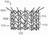
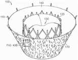
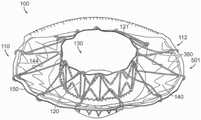
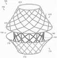
图10A显示根据本技术的实施例的人工心脏瓣膜装置的等距视图。10A shows an isometric view of a prosthetic heart valve device according to an embodiment of the present technology.
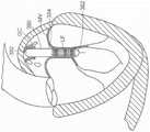
图10B显示心脏的剖视图,其显示根据本技术的实施例在天然二尖瓣植入的图10A的假体治疗装置。10B shows a cross-sectional view of a heart showing the prosthetic treatment device of FIG. 10A implanted in a native mitral valve in accordance with embodiments of the present technology.
图10C-10F分别是根据本技术的实施例的人工心脏瓣膜装置的侧视图、透视剖视图、俯视图和仰视图。10C-10F are a side view, a perspective cross-sectional view, a top view, and a bottom view, respectively, of a prosthetic heart valve device according to embodiments of the present technology.
图11A是根据本技术的实施例的处于扩张构型的瓣膜支撑件的侧视图。11A is a side view of a valve support in an expanded configuration in accordance with an embodiment of the present technology.
图11B-11D是根据本技术其中安装有人工瓣膜的瓣膜支撑件的另外实施例的等距视图。11B-11D are isometric views of additional embodiments of valve supports with a prosthetic valve installed therein in accordance with the present technology.
图11E显示根据本技术的另一个实施例的人工心脏瓣膜装置的等距视图。11E shows an isometric view of a prosthetic heart valve device according to another embodiment of the present technology.
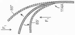
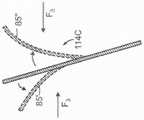
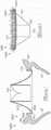
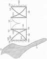
图12A-12C是根据本技术的其他实施例,响应于扭曲力而挠曲的各种纵肋的侧视图。12A-12C are side views of various longitudinal ribs that deflect in response to torsional forces in accordance with other embodiments of the present technology.
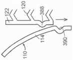
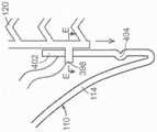
图13A是根据本技术的另一个实施例的人工心脏瓣膜装置的示意性截面视图。13A is a schematic cross-sectional view of a prosthetic heart valve device according to another embodiment of the present technology.
图13B-13F是根据本技术的另外实施例说明多种纵肋构型的人工心脏瓣膜装置的局部侧视图。13B-13F are partial side views of prosthetic heart valve devices illustrating various longitudinal rib configurations according to additional embodiments of the present technology.
图14A是说明主轴和副轴的天然二尖瓣示意性俯视图。Figure 14A is a schematic top view of a native mitral valve illustrating the major and minor axes.
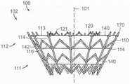
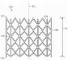
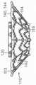
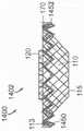
图14B-14C是根据本技术的实施例分别处于扩张构型和处于展开构型的锚定构件的示意性俯视图。14B-14C are schematic top views of anchoring members in an expanded configuration and in a deployed configuration, respectively, according to embodiments of the present technology.
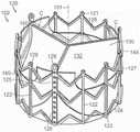
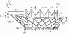
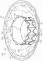
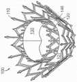
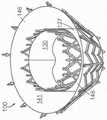
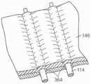
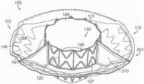
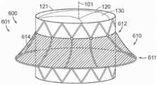
图15是根据本技术的另外实施例所显示处于展开构型的人工心脏瓣膜装置的等距视图。15 is an isometric view of a prosthetic heart valve device shown in a deployed configuration in accordance with further embodiments of the present technology.
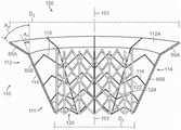
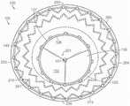
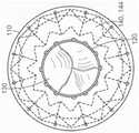
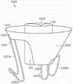
图16A是根据本技术的又另一个实施例所显示处于扩张构型的人工心脏瓣膜装置的俯视图。16A is a top view of a prosthetic heart valve device shown in an expanded configuration in accordance with yet another embodiment of the present technology.
图16B-16C分别是图16A人工心脏瓣膜装置的第一侧视图和第二侧视图。16B-16C are first and second side views, respectively, of the prosthetic heart valve device of FIG. 16A.
图16D是人工心脏瓣膜装置的侧视图,其显示根据本技术的另一个实施例与瓣膜支撑件的纵轴偏移某个倾斜角的锚定构件的纵轴。16D is a side view of a prosthetic heart valve device showing the longitudinal axis of the anchoring member offset by an oblique angle from the longitudinal axis of the valve support according to another embodiment of the present technology.
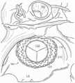
图16E是心脏中天然二尖瓣的示意性俯视图,该俯视图从左心房观察并显示根据本技术的实施例在天然二尖瓣处植入的图16A-16C的假体治疗装置。16E is a schematic top view of a native mitral valve in a heart, viewed from the left atrium and showing the prosthetic treatment device of FIGS. 16A-16C implanted at the native mitral valve in accordance with embodiments of the present technology.
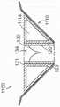
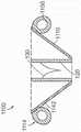
图17A-17C是图16A人工心脏瓣膜装置的示意性俯视图和第一和第二侧视图,该视图显示根据本技术实施例的装置的多个方面的尺度和锥角。17A-17C are schematic top views and first and second side views of the prosthetic heart valve device of FIG. 16A showing dimensions and taper angles of various aspects of the device according to embodiments of the present technology.
图18是根据本技术的又一个实施例所显示处于扩张构型的锚定构件的等距视图。18 is an isometric view of an anchoring member shown in an expanded configuration in accordance with yet another embodiment of the present technology.
图19A-19C分别是根据本技术的又一个实施例的具有密封构件的人工心脏瓣膜装置的等距视图、侧视图和俯视图。19A-19C are isometric, side, and top views, respectively, of a prosthetic heart valve device having a sealing member in accordance with yet another embodiment of the present technology.
图20A是根据本技术的实施例的没有密封构件的人工心脏瓣膜装置的等距视图。20A is an isometric view of a prosthetic heart valve device without a sealing member in accordance with an embodiment of the present technology.
图20B-20E是根据本技术的另外实施例的具有密封构件的人工心脏瓣膜装置的等距视图。20B-20E are isometric views of prosthetic heart valve devices with sealing members in accordance with further embodiments of the present technology.
图21A-21B是根据本技术的又一个实施例的具有管状瓣膜支撑构件的人工心脏瓣膜装置的横截侧视图和等距视图。21A-21B are cross-sectional side and isometric views of a prosthetic heart valve device having a tubular valve support member according to yet another embodiment of the present technology.
图21C-21F是根据本技术的其他实施例的具有管状瓣膜支撑构件的人工心脏瓣膜装置的局部截面侧视图和等距视图。21C-21F are partial cross-sectional side and isometric views of prosthetic heart valve devices having tubular valve support members in accordance with other embodiments of the present technology.
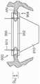
图22A-22G和22I-22K是根据本技术的另外实施例的连接瓣膜支撑件至锚定构件的多种机构的放大侧视图。22A-22G and 22I-22K are enlarged side views of various mechanisms for connecting a valve support to an anchoring member according to further embodiments of the present technology.
图22H是图40G人工心脏瓣膜装置中立柱的侧视图。Figure 22H is a side view of a post in the prosthetic heart valve device of Figure 40G.
图23A-23B是根据本技术的其他实施例的连接锚定构件至瓣膜支撑构件的另外机构的放大侧视图。23A-23B are enlarged side views of additional mechanisms for connecting an anchoring member to a valve support member according to other embodiments of the present technology.
图24A是根据本技术的另一实施例的在瓣膜支撑件和锚定构件之间的整体连接的透视图。24A is a perspective view of an integral connection between a valve support and an anchoring member according to another embodiment of the present technology.
图24B-24D是根据本技术的在瓣膜支撑件和锚定构件之间的整体连接的另外实施例的放大视图。24B-24D are enlarged views of additional embodiments of an integral connection between a valve support and an anchoring member in accordance with the present technology.
图25A是根据本技术的实施例的具有锚定构件和瓣膜支撑件的人工心脏瓣膜装置的局部截面视图。25A is a partial cross-sectional view of a prosthetic heart valve device having an anchoring member and a valve support in accordance with an embodiment of the present technology.
图25B是25A图中显示的命名框的放大视图。Figure 25B is an enlarged view of the naming box shown in Figure 25A.
图26A-26D是根据本技术的多种实施例的人工心脏瓣膜装置的示意性截面视图,该人工心脏瓣膜装置具有心房固位器并在天然二尖瓣植入。26A-26D are schematic cross-sectional views of a prosthetic heart valve device having an atrial retainer and implanted in a native mitral valve in accordance with various embodiments of the present technology.
图27是根据本技术的另一个实施例的锚定构件的侧视图,该锚定构件在上游端处具有用于接合瓣膜环的垂直部分。27 is a side view of an anchoring member having a vertical portion at an upstream end for engaging the valve annulus in accordance with another embodiment of the present technology.
图28是根据本技术的实施例的人工心脏瓣膜装置的侧视图,该人工心脏瓣膜装置处于扩张构型并且具有多个稳定部件。28 is a side view of a prosthetic heart valve device in an expanded configuration and having a plurality of stabilizing components in accordance with an embodiment of the present technology.
图29是根据本技术的实施例的人工心脏瓣膜装置的示意性放大侧视图,该人工心脏瓣膜装置具有延长臂。29 is a schematic enlarged side view of a prosthetic heart valve device having extended arms in accordance with an embodiment of the present technology.
图30A-30C是根据明技术的其他实施例的人工心脏瓣膜装置的局部放大侧视图,该人工心脏瓣膜装置具有相对于该装置的纵轴以多种角度与该装置连接的臂。30A-30C are enlarged partial side views of prosthetic heart valve devices having arms attached to the device at various angles relative to the device's longitudinal axis, according to other embodiments of the present technology.
图31A-31C是根据本技术的另外实施例的人工心脏瓣膜装置的局部放大侧视图,该人工心脏瓣膜装置具有与该装置连接的多种长度的臂。31A-31C are enlarged partial side views of prosthetic heart valve devices having arms of various lengths attached to the device in accordance with further embodiments of the present technology.
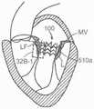
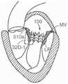
图32A、32B、32C和32D是植入根据本技术的多种实施例的人工心脏瓣膜装置的心脏的截面视图,该人工心脏瓣膜装置具有安置在瓣叶的向内表面上的臂。32A, 32B, 32C, and 32D are cross-sectional views of a heart implanted with a prosthetic heart valve device having arms disposed on the inward facing surfaces of the valve leaflets in accordance with various embodiments of the present technology.
图32A-1、32B-1、32C-1和32D-1是根据本技术的多种实施例分别如图32A、32B、32C和32D中所显示的臂的放大视图,这些臂接合瓣叶的向内表面。Figures 32A-1, 32B-1, 32C-1, and 32D-1 are enlarged views of the arms as shown in Figures 32A, 32B, 32C, and 32D, respectively, engaging the leaflets, according to various embodiments of the present technology. Inward surface.
图33A-33C是说明与根据本技术的人工心脏瓣膜装置一起使用的组织接合部件的多种实施例的示意图。33A-33C are schematic diagrams illustrating various embodiments of tissue engaging components for use with prosthetic heart valve devices according to the present technology.
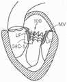
图34A、34B和34C是植入根据本技术的多种实施例的人工心脏瓣膜装置的心脏的截面视图,该人工心脏瓣膜装置具有组织接合部件安置在瓣叶的向内表面上的臂。34A, 34B, and 34C are cross-sectional views of a heart implanted with prosthetic heart valve devices having arms with tissue engaging members disposed on the inward facing surfaces of the valve leaflets in accordance with various embodiments of the present technology.
图34A-1、34B-1和34C-1是根据本技术的多种实施例分别如34A、 34B和34C中所显示的臂的放大视图,这些臂接合瓣叶的向内表面。34A-1 , 34B-1 and 34C-1 are enlarged views of the arms as shown in 34A, 34B and 34C, respectively, which engage the inward facing surfaces of the leaflets, according to various embodiments of the present technology.
图35A-35C是根据本技术的其他实施例的并显示在二尖瓣处植入 (以截面显示)的人工心脏瓣膜装置的侧视图,这些装置具有用于接合天然瓣叶的向外表面的臂。35A-35C are side views of prosthetic heart valve devices implanted (shown in cross-section) at the mitral valve having outer surfaces for engaging native valve leaflets, according to other embodiments of the present technology. arm.
图35C-1是根据本技术的多种实施例,如图35C中所显示的臂的放大视图,臂接合瓣叶的向内表面。35C-1 is an enlarged view of the arms as shown in FIG. 35C engaging the inward facing surfaces of the leaflets, in accordance with various embodiments of the present technology.
图36A是根据本技术的另外实施例的并显示在二尖瓣处植入(以截面显示)的人工心脏瓣膜装置的侧视图,该装置具有用于接合天然瓣叶的向外表面的臂和用于接合天然瓣叶的向内表面的臂。36A is a side view of a prosthetic heart valve device implanted at the mitral valve (shown in cross section) having arms for engaging the outward surfaces of the native leaflets and Arms for engaging the inward facing surfaces of the native leaflets.
图36B是如图36A中所显示的臂的放大视图,这些臂接合瓣叶的向内表面和向外表面。Figure 36B is an enlarged view of the arms as shown in Figure 36A engaging the inward and outward surfaces of the leaflets.
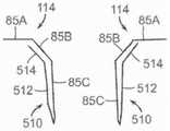
图37A-37D是臂的另外实施例的放大侧视图,这些臂适合随根据本技术的人工心脏瓣膜装置一起使用。37A-37D are enlarged side views of additional embodiments of arms suitable for use with prosthetic heart valve devices according to the present technology.
图38A是根据本技术的又一个实施例的具有多个非互联臂的人工心脏瓣膜装置的侧视图。38A is a side view of a prosthetic heart valve device having multiple non-interconnected arms in accordance with yet another embodiment of the present technology.
图38B是根据本技术的又一个实施例的具有多个环周连接臂的人工心脏瓣膜装置的侧视图。38B is a side view of a prosthetic heart valve device having a plurality of circumferential connecting arms in accordance with yet another embodiment of the present technology.
图39A-39D是根据本技术的另外实施例的臂位置图案的示意性俯视图。39A-39D are schematic top views of arm position patterns in accordance with further embodiments of the present technology.
图40A-40D是根据本技术的另外实施例的人工心脏瓣膜装置的侧视图,该人工心脏瓣膜装置具有在该装置的不同结构上的组织接合部件。40A-40D are side views of prosthetic heart valve devices having tissue engaging features on various structures of the device in accordance with further embodiments of the present technology.
图40E-40G是根据本技术的其他实施例的组织接合部件的放大侧视图,这些组织接合部件适合随人工心脏瓣膜装置一起使用。40E-40G are enlarged side views of tissue engaging components suitable for use with prosthetic heart valve devices according to other embodiments of the present technology.
图40H-40S是根据本技术的另外实施例的组织接合部件的放大侧视图,这些组织接合部件适合随人工心脏瓣膜装置一起使用。40H-40S are enlarged side views of tissue engaging components suitable for use with prosthetic heart valve devices according to further embodiments of the present technology.
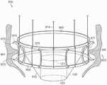
图41是根据本技术的又一个实施例的人工心脏瓣膜装置的等距视图,该人工心脏瓣膜装置具有多个瓣膜环结合部件。41 is an isometric view of a prosthetic heart valve device having a plurality of annulus engagement components in accordance with yet another embodiment of the present technology.
图42A-42B是根据本技术的另一个实施例的人工心脏瓣膜装置的横截侧视图和放大视图,该人工心脏瓣膜装置具有从多个管状肋可展开的组织接合部件。42A-42B are cross-sectional side and enlarged views of a prosthetic heart valve device having tissue engaging members deployable from a plurality of tubular ribs in accordance with another embodiment of the present technology.
图43A-43B是根据本技术的另一个实施例的人工心脏瓣膜装置的等距视图和放大细节视图,该人工心脏瓣膜装置具有与组织接合部件一起配置的密封构件。43A-43B are isometric and enlarged detail views of a prosthetic heart valve device having a sealing member deployed with a tissue engaging component in accordance with another embodiment of the present technology.
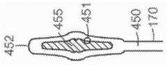
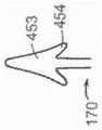
图44A-44F是根据本技术的另外实施例的组织接合部件的放大侧视图,这些组织接合部件适合随人工心脏瓣膜装置一起使用。44A-44F are enlarged side views of tissue engaging components suitable for use with prosthetic heart valve devices in accordance with further embodiments of the present technology.
图45A是根据本技术的实施例的人工心脏瓣膜装置的等距视图,该人工心脏瓣膜装置具有在锚定构件110和瓣膜支撑件120之间的多个系索。45A is an isometric view of a prosthetic heart valve device having a plurality of tethers between the anchoring
图45B是根据本技术的另一个实施例的人工心脏瓣膜装置的等距视图,该人工心脏瓣膜装置具有在锚定构件110和瓣膜支撑件120之间的多个隔膜。45B is an isometric view of a prosthetic heart valve device having a plurality of septa between the anchoring
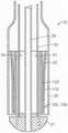
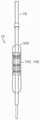
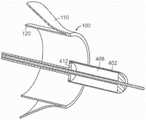
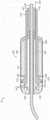
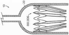
图46A是根据本技术的实施例的递送系统的侧面局部剖视图。46A is a side partial cutaway view of a delivery system in accordance with an embodiment of the present technology.
图46B是根据本技术的实施例的递送系统的远端的放大截面视图。46B is an enlarged cross-sectional view of the distal end of a delivery system according to an embodiment of the present technology.
图46C-46D是根据本技术的实施例的瓣膜支撑件的放大局部侧视图,该瓣膜支撑件配置为随图46B的递送系统一起使用。46C-46D are enlarged partial side views of a valve support configured for use with the delivery system of FIG. 46B in accordance with embodiments of the present technology.
图47A-47D是心脏截面视图,其显示根据本技术的实施例的顺行或经中隔至二尖瓣入路。47A-47D are cross-sectional views of the heart showing an antegrade or transseptal to mitral valve approach in accordance with embodiments of the present technology.
图48A-48C是心脏截面视图,其根据本技术的另一个实施例说明一种使用经中隔入路植入人工心脏瓣膜装置的方法。48A-48C are cross-sectional views of a heart illustrating a method of implanting a prosthetic heart valve device using a transseptal approach, according to another embodiment of the present technology.
图49A-49B是心脏截面视图,其根据本技术的又一个实施例显示经主动脉和左心室至二尖瓣的逆行入路。49A-49B are cross-sectional views of the heart showing a retrograde approach to the mitral valve through the aorta and left ventricle in accordance with yet another embodiment of the present technology.
图50A-50B是心脏截面视图,其根据本技术的多个方面说明一种使用经心尖入路植入人工心脏瓣膜装置的方法的又一个实施例。50A-50B are cross-sectional views of the heart illustrating yet another embodiment of a method of implanting a prosthetic heart valve device using a transapical approach in accordance with aspects of the present technology.
图51A-51B是根据本技术的另一个实施例的递送系统的局部侧视图,其中人工心脏瓣膜装置安装在递送导管的可扩张球囊上。51A-51B are partial side views of a delivery system according to another embodiment of the present technology with a prosthetic heart valve device mounted on an expandable balloon of a delivery catheter.
图52A-52D是心脏截面视图,其根据本技术的又一个实施例显示一种递送具有瓣膜支撑件的人工心脏瓣膜装置的方法,该瓣膜支撑件与锚定构件可活动地连接。52A-52D are cross-sectional views of a heart showing a method of delivering a prosthetic heart valve device having a valve support movably connected to an anchoring member in accordance with yet another embodiment of the present technology.
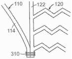
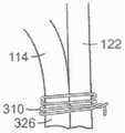
图53A-53D是显示根据本技术的另外实施例的多种机构的局部侧视图,这些机构用于可活动地连接瓣膜支撑件至锚定构件。53A-53D are partial side views showing various mechanisms for movably connecting a valve support to an anchoring member in accordance with further embodiments of the present technology.
图53E是图53D的装置的局部俯视图。Figure 53E is a partial top view of the device of Figure 53D.
图53F是根据本技术的另一个实施例的替代性机构的侧视图,该替代性机构用于可滑动地连接瓣膜支撑件和锚定构件。53F is a side view of an alternative mechanism for slidably connecting a valve support and an anchoring member according to another embodiment of the present technology.
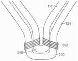
图53G-53H是根据本技术的又一个实施例的人工心脏瓣膜装置的示意性侧视图,其显示用于连接瓣膜支撑件至锚定构件的又一个机构。53G-53H are schematic side views of a prosthetic heart valve device according to yet another embodiment of the present technology, showing yet another mechanism for connecting a valve support to an anchoring member.
图54A是根据本技术的其他方面的递送系统的另一个实施例的截面侧视图,该递送系统用于人工心脏瓣膜装置。54A is a cross-sectional side view of another embodiment of a delivery system for a prosthetic heart valve device in accordance with other aspects of the present technology.
图54B是图54A的递送系统的远端部分的局部截面侧视图。Figure 54B is a partial cross-sectional side view of the distal portion of the delivery system of Figure 54A.
图55A-55C是图46的递送系统的透视图,其说明递送本假体治疗装置的步骤。55A-55C are perspective views of the delivery system of FIG. 46 illustrating the steps of delivering the present prosthetic treatment device.
图56是用于本假体治疗装置的递送系统的又一个实施例的侧面截面视图。56 is a side cross-sectional view of yet another embodiment of a delivery system for use with the present prosthetic treatment device.
图57A-57D是根据本技术的另外实施例的假体治疗装置的等距视图。57A-57D are isometric views of prosthetic treatment devices according to further embodiments of the present technology.
图57E是根据本技术的实施例的图57A人工心脏瓣膜装置的示意性截面视图,该人工心脏瓣膜装置在天然二尖瓣植入。57E is a schematic cross-sectional view of the prosthetic heart valve device of FIG. 57A implanted in a native mitral valve in accordance with an embodiment of the present technology.
图58A-58D是心脏截面视图,其根据本技术的另一个实施例显示一种使用经心尖入路递送人工心脏瓣膜装置至心脏中天然二尖瓣的方法。58A-58D are cross-sectional views of the heart showing a method of delivering a prosthetic heart valve device to the native mitral valve in the heart using a transapical approach in accordance with another embodiment of the present technology.
图59A-59C是根据本技术的另外实施例的假体治疗装置的等距视图。59A-59C are isometric views of prosthetic treatment devices according to further embodiments of the present technology.
图59D是根据本技术的另一个实施例在天然二尖瓣植入的人工心脏瓣膜装置的示意性截面视图。59D is a schematic cross-sectional view of a prosthetic heart valve device implanted in a native mitral valve according to another embodiment of the present technology.
图60A-60B是根据本技术的另一个实施例的递送导管的远端的截面侧视图,该递送导管用于递送图59C的人工心脏瓣膜装置至心脏中的天然二尖瓣。60A-60B are cross-sectional side views of the distal end of a delivery catheter for delivering the prosthetic heart valve device of FIG. 59C to the native mitral valve in the heart in accordance with another embodiment of the present technology.
图61是根据本技术的又一个实施例的人工心脏瓣膜装置的侧视图,该人工心脏瓣膜装置具有用于分别接合二尖瓣的瓣膜环上方组织和瓣膜环下方组织的第一和第二锚定构件。61 is a side view of a prosthetic heart valve device having first and second anchors for engaging supra-annular and sub-annular tissue of the mitral valve, respectively, in accordance with yet another embodiment of the present technology fixed component.
图62A-62C是根据本技术的另一个实施例的递送系统远端的局部截面侧视图,其显示在二尖瓣递送图61的人工心脏瓣膜装置。62A-62C are partial cross-sectional side views of the distal end of a delivery system showing delivery of the prosthetic heart valve device of FIG. 61 at the mitral valve in accordance with another embodiment of the present technology.
图63是根据本技术的又一个实施例的人工心脏瓣膜装置的等距侧视图,该人工心脏瓣膜装置具有带瓣膜环上方接合凸缘和瓣膜环下方接合环的锚定构件。63 is an isometric side view of a prosthetic heart valve device having an anchoring member with a supra-annular coaptation flange and a sub-annular coaptation ring in accordance with yet another embodiment of the present technology.
图64A-64D是图63的人工心脏瓣膜装置的侧视图,其根据本技术的多个方面显示在二尖瓣膜环处展开该装置的方法的实施例。64A-64D are side views of the prosthetic heart valve device of FIG. 63 showing an embodiment of a method of deploying the device at the mitral valve annulus in accordance with aspects of the present technology.
图65A是根据本披露的另一个实施例的人工心脏瓣膜装置的截面视图,该人工心脏瓣膜装置具有可膨胀锚定构件并被显示植入心脏的天然二尖瓣中。65A is a cross-sectional view of a prosthetic heart valve device having an expandable anchoring member and shown implanted in the native mitral valve of the heart, according to another embodiment of the present disclosure.
图65B是根据本技术的另一个实施例的递送系统远端的局部截面侧视图,该递送系适于递送图65A的人工心脏瓣膜装置。65B is a partial cross-sectional side view of the distal end of a delivery system adapted to deliver the prosthetic heart valve device of FIG. 65A in accordance with another embodiment of the present technology.
图66A-66D是根据本技术的另外实施例的人工心脏瓣膜装置的截面视图,该人工心脏瓣膜装置具有可充盈室。66A-66D are cross-sectional views of prosthetic heart valve devices having inflatable chambers in accordance with further embodiments of the present technology.
图67A-67B是根据本技术的多个方面的人工心脏瓣膜装置的另外实施例的等距视图。67A-67B are isometric views of additional embodiments of prosthetic heart valve devices in accordance with aspects of the present technology.
图68A-68B是根据本技术的一个另外实施例的人工心脏瓣膜装置的侧视图,该人工心脏瓣膜装置具有定位部件。68A-68B are side views of a prosthetic heart valve device having positioning features in accordance with an additional embodiment of the present technology.
图69A-69E是人工心脏瓣膜装置的截面和侧视图,这些人工心脏瓣膜装置显示处于扩张构型并且根据本技术的另外实施例被配置。69A-69E are cross-sectional and side views of prosthetic heart valve devices shown in an expanded configuration and configured in accordance with further embodiments of the present technology.
图70是根据本技术的实施例配置的另一个人工心脏瓣膜装置的截面侧视图。70 is a cross-sectional side view of another prosthetic heart valve device configured in accordance with embodiments of the present technology.
图71是根据本技术的实施例配置的又一个人工心脏瓣膜装置的截面侧视图。71 is a cross-sectional side view of yet another prosthetic heart valve device configured in accordance with embodiments of the present technology.
发明详述Detailed description of the invention
下文参考图1-71描述该技术的几个实施例的具体细节。虽然下文相对于使用人工瓣膜装置透皮替换天然二尖瓣的装置、系统和方法描述了许多实施例,但是除本文所述的那些之外,其他应用和其他实施例也处于本技术的范围内。另外,本技术的几个其他实施例可以具有与本文所述的那些不同的构型、组件或程序。因此,本领域技术人员,将因此理解本技术可以具有采用另外部件的其他实施例,或本技术可以在不具有下文参考图1-71所显示和描述的几个特征的情况下,具有其他实施例。Specific details of several embodiments of the technique are described below with reference to FIGS. 1-71 . While many embodiments are described below with respect to devices, systems, and methods for transdermal replacement of a native mitral valve using a prosthetic valve device, other applications and other embodiments than those described herein are also within the scope of the present technology . Additionally, several other embodiments of the present technology may have configurations, components, or procedures that differ from those described herein. Accordingly, those skilled in the art will therefore appreciate that the technology may have other embodiments employing additional components, or that the technology may have other implementations without several of the features shown and described below with reference to FIGS. 1-71 . example.
除非另外说明,否则就本说明书内部的术语“远端”和“近端”而言,这些术语可以指人工瓣膜装置和/或相关递送装置的多个部分相对于操作者和/或血管系统或心脏中某位置的相对位置。例如,在提到适于递送和定位本文所述的各种人工瓣膜装置的递送导管时,“近端”可以指更靠近该装置操作员或血管系统切口的位置,并且“远端”可以指距离该装置操作员较远或沿血管系统的切口更远的位置(例如,导管的末端)。相对于人工心脏瓣膜装置,术语“近端”和“远端”可以指该装置的多个部分相对于血液流动方向的位置。例如,近端可以指上游位置或血液入流位置,并且远端可以指下游位置或血液出流位置。为易于参考,在本披露通篇范围,相同指示符和/或字母用来确定相似或类似的组件或特征,但是相同指示符的使用不暗示该零件应当是解读为是相同的。实际上,在本文所述的许多实例中,相同编号的零件在结构和/或功能方面是不同的。本文提供的标题仅为方便起见。Unless otherwise specified, with respect to the terms "distal" and "proximal" within this specification, these terms may refer to portions of the prosthetic valve device and/or associated delivery device relative to the operator and/or the vascular system or The relative position of a location in the heart. For example, in reference to delivery catheters suitable for delivering and positioning the various prosthetic valve devices described herein, "proximal" may refer to a location closer to the device operator or vascular system incision, and "distal" may refer to A location that is further from the operator of the device or along the incision of the vascular system (eg, the tip of the catheter). With respect to a prosthetic heart valve device, the terms "proximal end" and "distal end" may refer to the position of various parts of the device relative to the direction of blood flow. For example, the proximal end may refer to the upstream location or blood inflow location, and the distal end may refer to the downstream location or blood outflow location. For ease of reference, throughout this disclosure, the same designators and/or letters are used to identify similar or similar components or features, but the use of the same designators does not imply that the parts should be read as identical. In fact, in many of the examples described herein, like-numbered parts differ in structure and/or function. The headings provided herein are for convenience only.
概述Overview
本文提供了用于透皮替换天然心脏瓣膜如二尖瓣的系统、装置和方法。提供下文所述的几项详细内容以便按这样的方式描述以下实例和方法,该方式足以使相关领域技术人员实施、制造和使用它们成为可能。然而,下文描述的几项详细内容和优点可以不是实施本技术的某些实例和方法必需的。另外,本技术可以包括处于权利要求书范围内但未详述的其他实例和方法。Provided herein are systems, devices, and methods for transdermal replacement of native heart valves, such as the mitral valve. The several details set forth below are provided in order to describe the following examples and methods in a manner sufficient to enable those skilled in the relevant art to make, make, and use them. However, several of the details and advantages described below may not be required to implement certain examples and methods of the present technology. Additionally, the technology may include other examples and methods that are within the scope of the claims but not recited in detail.
本技术的实施例提供了治疗身体瓣膜如心脏瓣膜(包括二尖瓣)的系统、方法和装置。这些装置和方法使得利用导管的透皮方法成为可能,其中该导管经静脉或动脉按血管内方式递送至心脏中。另外,这些装置和方法使得侵入性较小的其他方法成为可能,所述其他方法包括经心尖、经心房和直接主动脉递送假体替换瓣膜装置心脏中的靶位置。这些装置和方法使得假体装置通过与瓣膜环和/或瓣叶的瓣膜环下方表面接合锚定在天然瓣膜位置处成为可能。另外,如本文所述的装置和方法的实施例可以与许多已知的外科术和手术组合,如采用顺行或逆行入路及它们的组合抵达心脏瓣膜(例如,二尖瓣或三尖瓣)的已知方法。Embodiments of the present technology provide systems, methods, and devices for treating body valves, such as heart valves, including the mitral valve. These devices and methods enable transdermal approaches using catheters that are delivered intravascularly into the heart via veins or arteries. Additionally, these devices and methods enable other less invasive methods including transapical, transatrial, and direct aortic delivery of prosthetic replacement valve devices to target sites in the heart. These devices and methods enable the prosthetic device to be anchored at the native valve location by engaging with the subannular surface of the valve annulus and/or the valve leaflets. Additionally, embodiments of the devices and methods as described herein can be combined with many known surgeries and procedures, such as using antegrade or retrograde approaches and combinations thereof to reach heart valves (eg, mitral or tricuspid valves) ) known methods.
本文所述的装置和方法提供一种瓣膜替换装置,其具有适应于并且贴合形状各异的天然二尖瓣解剖学的柔韧度,同时使人工瓣膜与装置的锚定部分机械地分离。该装置的几个实施例有效地吸收因天然解剖学施加的扭曲力。该装置具有随时间推移经受心脏动态状况所必需的结构性强度和完整性,因此牢固地锚定替换瓣膜并且使得患者可能过上实质地正常的生活。这些装置和方法进一步以侵入性较小的方式递送这种装置,不仅为患者提供新的永久替换瓣膜,还提供风险较低的手术和更快的恢复。The devices and methods described herein provide a valve replacement device that has the flexibility to accommodate and conform to the anatomy of the native mitral valve of varying shapes, while mechanically separating the prosthetic valve from the anchoring portion of the device. Several embodiments of the device effectively absorb twisting forces imposed by natural anatomy. The device has the structural strength and integrity necessary to withstand the dynamic conditions of the heart over time, thus firmly anchoring the replacement valve and making it possible for the patient to lead a substantially normal life. These devices and methods further deliver such devices in a less invasive manner, providing patients not only with new permanent replacement valves, but also with less risky procedures and faster recovery.
根据本技术的多种实施例,披露了一种用于修复或替换心脏天然瓣膜的装置。天然瓣膜具有瓣膜环和瓣叶,并且该装置包括具有第一部分的锚定构件,该第一部分配置成接合在所述瓣膜环上或在其下的组织并以非圆形状变形以贴合该组织。该锚定构件还可以包括第二部分。该装置还包括瓣膜支撑件,该瓣膜支撑件与锚定构件的第二部分连接并配置成支撑人工瓣膜并且具有截面形状。在多种实施例中,锚定构件的第一部分机械地与瓣膜支撑件隔离,从而瓣膜支撑件的截面形状保持充分稳定,从而该人工瓣膜在锚定构件以非圆形状变形时保持有效。According to various embodiments of the present technology, a device for repairing or replacing a native valve of the heart is disclosed. The native valve has a valve annulus and valve leaflets, and the device includes an anchoring member having a first portion configured to engage tissue on or below the valve annulus and deform in a non-circular shape to conform to the tissue . The anchoring member may also include a second portion. The device also includes a valve support coupled to the second portion of the anchoring member and configured to support the prosthetic valve and having a cross-sectional shape. In various embodiments, the first portion of the anchoring member is mechanically isolated from the valve support such that the cross-sectional shape of the valve support remains sufficiently stable such that the prosthetic valve remains effective when the anchoring member deforms in a non-circular shape.
本披露的一些实施例涉及用于在天然二尖瓣处植入的人工心脏瓣膜装置,其中该二尖瓣具有瓣膜环和瓣叶。在一个实施例中,该装置可以具有可定位在瓣叶之间的位置内的锚定构件,其中该锚定构件的第一部分可扩张至比瓣膜环相应尺度更大的尺度。在这个实施例中,锚定构件的上行移动因上游部分与瓣膜环上或其附近的组织的接合而被阻挡。锚定构件也可以包括第二部分。该装置也可以包括与锚定构件的第二部分连接的瓣膜支撑件,其中该瓣膜支撑件的上游区域径向内向地与至少锚定构件的第一部分隔开。该瓣膜支撑件可以配置成支撑人工瓣膜。Some embodiments of the present disclosure relate to prosthetic heart valve devices for implantation at a native mitral valve, wherein the mitral valve has a valve annulus and valve leaflets. In one embodiment, the device may have an anchoring member positionable in a position between the leaflets, wherein the first portion of the anchoring member is expandable to a dimension larger than the corresponding dimension of the valve annulus. In this embodiment, upward movement of the anchoring member is blocked by the engagement of the upstream portion with tissue on or near the valve annulus. The anchoring member may also include a second portion. The device may also include a valve support coupled to the second portion of the anchoring member, wherein an upstream region of the valve support is spaced radially inwardly from at least the first portion of the anchoring member. The valve support can be configured to support a prosthetic valve.
在另一个安排中,用于在具有瓣膜环和瓣叶的天然瓣膜处植入的装置可以包括具有上游端和下游端的双曲线锚定构件,该上游端配置成接合瓣膜环下游瓣叶的向内表面,其中上游端具有比下游端更大的横截面积。该装置也可以包括定位在锚定构件中并配置成支撑人工瓣膜的瓣膜支撑件。该瓣膜支撑件实质地与上游端下游间隔的位置处与该锚定构件连接并且在上游端处不与该锚定构件连接。In another arrangement, a device for implantation at a native valve having an annulus and leaflets may include a hyperbolic anchoring member having an upstream end and a downstream end configured to engage the direction of the leaflets downstream of the annulus. The inner surface, wherein the upstream end has a larger cross-sectional area than the downstream end. The device may also include a valve support positioned in the anchoring member and configured to support the prosthetic valve. The valve support is connected to the anchoring member at a location substantially spaced downstream from the upstream end and is not connected to the anchoring member at the upstream end.
本披露的其他方面涉及用于修复或替换患者的天然心脏瓣膜的人工心脏瓣膜装置,其中该心脏瓣膜具有瓣膜环和瓣叶。在一个实施例中,该装置包括具有第一部分和第二部分的锚定构件,该第一部分具有第一截面尺度,该第二部分具有小于第一截面尺度的第二截面尺。第一部分配置成接合心脏组织以保持锚定构件处在相对于瓣膜环的固定纵向位置。该装置也可以包括与锚定构件的第二部分连接并配置成支撑人工瓣膜的瓣膜支撑件。该瓣膜支撑件可以径向地与锚定构件的第一部分分隔,从而第一部分可以在不使瓣膜支撑件实质地变形的情况下内向地变形。Other aspects of the present disclosure relate to prosthetic heart valve devices for repairing or replacing a patient's native heart valve, wherein the heart valve has a valve annulus and valve leaflets. In one embodiment, the device includes an anchoring member having a first portion having a first cross-sectional dimension and a second portion having a second cross-sectional dimension that is smaller than the first cross-sectional dimension. The first portion is configured to engage cardiac tissue to maintain the anchoring member in a fixed longitudinal position relative to the valve annulus. The device may also include a valve support coupled to the second portion of the anchoring member and configured to support the prosthetic valve. The valve support may be radially spaced from the first portion of the anchoring member such that the first portion may deform inwardly without substantially deforming the valve support.
在又一个安排中,本披露还涉及一种在天然心脏瓣膜处植入的装置。该装置可以包括一种锚定构件,该锚定构件具有配置成接合在心脏瓣膜的天然瓣膜环上的或下游的组织的上游端和配置成支撑人工瓣膜的瓣膜支撑件。该瓣膜支撑件可以与该锚定构件连接。在一些安排中,该锚定构件可以在该装置的部件不在天然瓣叶后延伸的情况下抵抗该装置的上行迁移。In yet another arrangement, the present disclosure also relates to a device implanted at a native heart valve. The device may include an anchoring member having an upstream end configured to engage tissue on or downstream of a native annulus of the heart valve and a valve support configured to support the prosthetic valve. The valve support can be connected to the anchoring member. In some arrangements, the anchoring member may resist upward migration of the device without components of the device extending posterior to the native leaflets.
在另一个实施例中,该装置可以包括可定位在天然瓣膜的瓣叶之间的锚定构件。该锚定构件可以具有在上游端上和/或在外表面上的多个组织接合部件,这些组织接合部件配置成接合在瓣膜环上或其附近的心脏组织,从而防止该装置以上游方向迁移。该装置也可以包括定位在锚定构件内部并且与锚定构件的下游部分连接的瓣膜支撑件,其中该瓣膜支撑件径向地与至少锚定构件的上游部分分隔。In another embodiment, the device may include an anchoring member positionable between leaflets of the native valve. The anchoring member may have a plurality of tissue engaging features on the upstream end and/or on the outer surface configured to engage cardiac tissue on or near the valve annulus to prevent migration of the device in the upstream direction. The device may also include a valve support positioned within the anchoring member and connected to the downstream portion of the anchoring member, wherein the valve support is radially spaced from at least the upstream portion of the anchoring member.
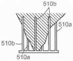
本披露的其他实施例涉及一种用于修复或替换具有瓣膜环和一对瓣叶的天然二尖瓣的装置,该装置包括支撑结构,该支撑结构具有上部区域、下部区域和保持人工瓣膜的内部。该装置也可以包括围绕该支撑结构的至少一部分的锚定构件,其中该锚定构件可定位在瓣叶之间并且具有以菱形图案排列的多个柔性部件(例如,金属线、激光切割的金属部件等)、上部分和下部分。该锚定构件的上部分可以以近端方向外向展开,从而这些柔性部件的近端径向外向地指向,从而接合在瓣膜环上或其附近的心脏组织并抑制该装置以上游方向迁移。该支撑结构的下部区域可以与该锚定构件的下部分连接,并且该支撑结构的下部区域可以机械地与至少该锚定构件的展开的上部分的变形相隔离。Other embodiments of the present disclosure relate to a device for repairing or replacing a native mitral valve having a valve annulus and a pair of leaflets, the device including a support structure having an upper region, a lower region, and a prosthetic valve retaining mechanism internal. The device may also include an anchoring member surrounding at least a portion of the support structure, wherein the anchoring member is positionable between the leaflets and has a plurality of flexible components (eg, wire, laser-cut metal) arranged in a diamond pattern parts, etc.), upper and lower parts. The upper portion of the anchoring member can be deployed proximally outwardly so that the proximal ends of the flexible members are directed radially outwardly to engage cardiac tissue on or near the valve annulus and inhibit migration of the device in the upstream direction. The lower region of the support structure may be connected to the lower portion of the anchoring member, and the lower region of the support structure may be mechanically isolated from deformation of at least the deployed upper portion of the anchoring member.
本披露的其他实施例涉及一种人工心脏瓣膜装置,其具有圆柱状支撑件和由独立于该圆柱状支撑件的结构限定的锚定件。该圆柱状支撑件可以具有纵轴和血液可以经其流过的沿该纵轴的内部。该锚定件可以具有非圆截面,同时外向展开的上游端配置成接合二尖瓣的瓣膜环下方组织。该锚定件也可以围绕圆柱状支撑件并且与该支撑件在与上游端相对的下游端处连接。Other embodiments of the present disclosure relate to a prosthetic heart valve device having a cylindrical support and an anchor defined by a structure independent of the cylindrical support. The cylindrical support may have a longitudinal axis and an interior along the longitudinal axis through which blood may flow. The anchor may have a non-circular cross-section with the outwardly deployed upstream end configured to engage subannular tissue of the mitral valve. The anchor may also surround the cylindrical support and be connected to the support at the downstream end opposite the upstream end.
在又一个实施例中,该装置可以包括配置成放置在两个瓣叶之间的可扩张瓣膜支撑件。该支撑可以具有第一区域、第二区域和其中可以连接瓣膜的内部。该装置也可以包括具有第一部分和第二部分的锚定构件,该第二部分与瓣膜支撑件的第二区域连接。该锚定构件的第一部分可以外向地延伸远离第二部分。该锚定构件可以在第一部分处具有第一周长,该第一周长配置成接合瓣膜环上或其附近的组织。该锚定构件可以机械地与该瓣膜支撑件隔离,从而在第一周长处或其附近径向发出的力将不实质地改变该瓣膜支撑件的形状。In yet another embodiment, the device may include an expandable valve support configured to be placed between two leaflets. The support may have a first region, a second region, and an interior in which the valve may be attached. The device can also include an anchoring member having a first portion and a second portion, the second portion being connected to the second region of the valve support. The first portion of the anchoring member may extend outwardly away from the second portion. The anchoring member may have a first perimeter at the first portion, the first perimeter configured to engage tissue on or near the valve annulus. The anchoring member may be mechanically isolated from the valve support so that radially emanating forces at or near the first perimeter will not substantially alter the shape of the valve support.
另外的实施例涉及治疗患者的心脏瓣膜的装置,该装置包括内框架和与内框架连接的外框架。内框架可以具有配置成支撑人工瓣膜的外表面和内表面。外框架可以具有截面尺度比二尖瓣膜环的相应截面尺度更大的上部分,其中该上部分配置成接合二尖瓣的瓣膜环处或以下的组织。上部分也可以防止该装置在心室收缩期期间以向上或上游方向迁移。另外,外框架的上部分可以机械地与内框架隔离。Additional embodiments relate to a device for treating a patient's heart valve, the device including an inner frame and an outer frame coupled to the inner frame. The inner frame may have outer and inner surfaces configured to support the prosthetic valve. The outer frame may have an upper portion having a larger cross-sectional dimension than a corresponding cross-sectional dimension of the mitral valve annulus, wherein the upper portion is configured to engage tissue at or below the mitral valve annulus. The upper portion may also prevent the device from migrating in an upward or upstream direction during ventricular systole. Additionally, the upper portion of the outer frame may be mechanically isolated from the inner frame.
在又一个实施例中,该装置可以包括圆柱状内骨架和与内骨架连接并可定位在瓣膜环下游的瓣叶之间的外骨架。外骨架可以可变形成非圆截面,同时内骨架在截面上实质地保持圆形。内骨架可以具有人工瓣膜可以与之连接的内部。外骨架可以具有多个柔性部件(例如,金属线、激光切割的金属部件等),其中这些柔性部件的至少一部分可以是配置成接合瓣膜环下方天然组织,从而防止该装置以上游方向迁移。在一个实施例中,多根柔性金属线以菱形构型排列。In yet another embodiment, the device may include a cylindrical endoskeleton and an exoskeleton connected to the endoskeleton and positioned between the valve leaflets downstream of the valve annulus. The exoskeleton can be variably formed into a non-circular cross-section, while the inner framework remains substantially circular in cross-section. The endoskeleton may have an interior to which the prosthetic valve may be attached. The exoskeleton may have flexible components (eg, wires, laser-cut metal components, etc.), wherein at least a portion of these flexible components may be configured to engage native tissue beneath the annulus, thereby preventing migration of the device in the upstream direction. In one embodiment, the plurality of flexible metal wires are arranged in a diamond-shaped configuration.
在又一个实施例中,一种人工二尖瓣装置可以包括瓣膜支撑件,该瓣膜支撑件具有上游端及下游端、其中可以连接瓣膜的内部、和周长。该装置也可以包括锚定构件,该锚定构件具有展开的上游部分和与瓣膜支撑件的周长连接的下游部分。上游部分可以机械地与瓣膜支撑件隔离并且可以配置成接合天然二尖瓣的瓣膜环下方组织。另外地,该装置可以可变动成多个构型,该多个构型包括其中该瓣膜支撑件和该锚定构件径向收缩的第一构型,并且其中该瓣膜支撑件具有第一截面形状。该装置也可以变动成第二构型,其中该瓣膜支撑件和该锚定构件径向扩张并且其中该瓣膜支撑件具有第二截面形状。另外地,该装置可以变动成第三构型,其中该锚定构件与瓣膜环下方组织结合并且因其变形,同时该瓣膜支撑件仍处于第二截面形状。In yet another embodiment, a prosthetic mitral valve device can include a valve support having an upstream end and a downstream end, an interior in which a valve can be connected, and a perimeter. The device may also include an anchoring member having a deployed upstream portion and a downstream portion connected to the perimeter of the valve support. The upstream portion can be mechanically isolated from the valve support and can be configured to engage subannular tissue of the native mitral valve. Additionally, the device may be moveable into a plurality of configurations including a first configuration in which the valve support and the anchoring member are radially contracted, and wherein the valve support has a first cross-sectional shape . The device can also be changed to a second configuration wherein the valve support and the anchoring member are radially expanded and wherein the valve support has a second cross-sectional shape. Additionally, the device can be moved into a third configuration in which the anchoring member engages and deforms the subannular tissue while the valve support remains in the second cross-sectional shape.
在一些实施例中,该装置可以包括心房固位器,该心房固位器从锚定构件或瓣膜支撑件延伸至至少部分地上游于天然二尖瓣膜环的位置。心房延伸构件可以包括适应于接合瓣膜环上游表面(例如,瓣膜环上方表面)和/或心房内壁以便进一步稳定或锚定该装置的心房接合结构。例如,心房固位器可以阻挡该装置的下行移动。In some embodiments, the device may include an atrial retainer extending from the anchoring member or valve support to a location at least partially upstream of the native mitral valve annulus. The atrial extension member may include an atrial engagement structure adapted to engage the upstream surface of the valve annulus (eg, the upper surface of the valve annulus) and/or the inner wall of the atrium to further stabilize or anchor the device. For example, an atrial retainer can block descending movement of the device.
该装置的一些实施例还可以包括抑制该装置倾斜或横向移位的一个或多个稳定构件。这些稳定构件可以包括从瓣膜支撑件和/或锚定构件径向外向延伸的多条臂。这些臂可以配置成在天然瓣叶后延伸和/ 或配置成与心室壁或乳头肌接合。Some embodiments of the device may also include one or more stabilizing members that inhibit tilting or lateral displacement of the device. These stabilizing members may include arms extending radially outward from the valve support and/or anchoring member. The arms can be configured to extend behind the native leaflets and/or to engage the ventricular wall or papillary muscles.
根据本披露的另一个方面,又一个实施例涉及在天然二尖瓣处植入的装置,其中天然二尖瓣具有瓣膜环和瓣叶。该装置可以包括瓣膜支撑件,该瓣膜支撑件具有上游端和下游端、其中可以连接瓣膜的内部、和外表面,并且包括第一锚定构件,该第一锚定构件具有展开的第一上游部分和第一下游部分,该第一下游部分与瓣膜支撑件的外表面连接。在其他实施例中,第一下游部分可以与瓣膜支撑件的内表面连接,或在一些实施例中,与瓣膜支撑件的末端连接。该装置也可以包括至少部分地围绕第一锚定构件的第二锚定构件。第一锚定构件的第一上游部分可以机械地与瓣膜支撑件隔离并且配置成接合天然二尖瓣的瓣膜环上方组织。第二锚定构件可以具有展开的第二上游部分和与瓣膜支撑件的外表面连接的第二下游部分,其中该第二上游部分可以机械地与瓣膜支撑件隔离并且配置成接合天然二尖瓣的瓣膜环下方组织。According to another aspect of the present disclosure, yet another embodiment relates to a device implanted at a native mitral valve, wherein the native mitral valve has a valve annulus and valve leaflets. The device can include a valve support having upstream and downstream ends in which the inner and outer surfaces of the valve can be connected, and a first anchoring member having a deployed first upstream end portion and a first downstream portion connected to the outer surface of the valve support. In other embodiments, the first downstream portion may be attached to the inner surface of the valve support, or in some embodiments, to the distal end of the valve support. The device may also include a second anchor member at least partially surrounding the first anchor member. The first upstream portion of the first anchoring member can be mechanically isolated from the valve support and configured to engage supra-annular tissue of the native mitral valve. The second anchoring member can have a deployed second upstream portion and a second downstream portion connected to the outer surface of the valve support, wherein the second upstream portion can be mechanically isolated from the valve support and configured to engage the native mitral valve tissue beneath the valve annulus.
在又一个实施例中,用于植入的装置可以包括配置成接合瓣膜环上的或下游的天然组织的径向扩张的锚定构件。锚定构件可以在面向后瓣叶的侧面上具有第一纵长度并且在面向前瓣叶的侧面上具有第二长度。在某些实施例中,第一长度可以大于第二长度,从而对左心室流出道(LVOT)的堵塞是有限的。该装置也可以包括与锚定构件的内部或与其末端连接的瓣膜支撑件或可替代地人工瓣膜。In yet another embodiment, a device for implantation may include a radially expanded anchoring member configured to engage native tissue on or downstream of the valve annulus. The anchoring member may have a first longitudinal length on the side facing the posterior leaflet and a second length on the side facing the anterior leaflet. In certain embodiments, the first length may be greater than the second length so that occlusion of the left ventricular outflow tract (LVOT) is limited. The device may also include a valve support or alternatively a prosthetic valve attached to the interior of the anchoring member or to its distal end.
本技术的其他实施例提供一种在具有瓣膜环和瓣叶的天然二尖瓣处植入的装置,其中该装置包括瓣膜支撑件,该瓣膜支撑件具有上游端和下游端、其中可以连接瓣膜的内部、和外表面。该装置也可以包括锚定构件,该锚定构件具有展开的上游部分和与瓣膜支撑件的外表面连接的下游部分,其中该上游部分可以具有上部环和与该上部环连接的下部环。该装置还可以包括围绕该锚定构件的周线分布并连接上部环至下部环的多个柔性瓣膜环结合部件。该下部环配置成以上游方向移向上部环,从而在上部环和下部环之间并在瓣膜环结合部件内部接收瓣膜环。Other embodiments of the present technology provide a device implanted at a native mitral valve having a valve annulus and valve leaflets, wherein the device includes a valve support having an upstream end and a downstream end in which the valve can be attached internal and external surfaces. The device may also include an anchoring member having a deployed upstream portion and a downstream portion connected to the outer surface of the valve support, wherein the upstream portion may have an upper ring and a lower ring connected to the upper ring. The device may also include a plurality of flexible annulus engagement members distributed around the circumference of the anchoring member and connecting the upper annulus to the lower annulus. The lower annulus is configured to move toward the upper annulus in an upstream direction to receive the valve annulus between the upper and lower annulus and within the annulus engagement member.
本披露进一步提供用于使用血管内或其他侵入性最小的抵达形式递送人工瓣膜和其他装置的系统。例如,本技术的实施例提供一种治疗患者的二尖瓣的系统,其中二尖瓣具有瓣膜环。该系统包括如本文所述的治疗二尖瓣的装置和具有管腔的导管,该管腔配置成将该装置保留在导管内部。The present disclosure further provides systems for delivering prosthetic valves and other devices using intravascular or other minimally invasive forms of delivery. For example, embodiments of the present technology provide a system for treating a patient's mitral valve, wherein the mitral valve has a valve annulus. The system includes a device for treating a mitral valve as described herein and a catheter having a lumen configured to retain the device inside the catheter.
在其他方面,提供一种用于替换患者中天然瓣膜的系统。该系统可以包括延长的导管体,该导管体具有远端和近端,以及与连接导管体远端并具有闭合末端和开放末端的壳体。该系统也可以包括在壳体内部的柱塞,该柱塞相对于壳体轴向是可移动,和致动器,该致动器在导管体近端处并与该柱塞如此连接,从而移动该致动器轴向地相对于该柱塞移动该壳体。该系统还可以包括具有坍缩构型和扩张构型的人工瓣膜装置。该人工瓣膜装置可以按坍缩构型可定位在壳体中并且可以从壳体通过移动致动器近端地可释放。In other aspects, a system for replacing a native valve in a patient is provided. The system can include an elongated catheter body having a distal end and a proximal end, and a housing connected to the distal end of the catheter body and having closed and open ends. The system may also include a plunger inside the housing, the plunger being axially movable relative to the housing, and an actuator at the proximal end of the catheter body and connected to the plunger such that Moving the actuator moves the housing axially relative to the plunger. The system can also include a prosthetic valve device having a collapsed configuration and an expanded configuration. The prosthetic valve device may be positionable in the housing in a collapsed configuration and may be proximally releasable from the housing by moving the actuator.
在又一个方面,本发术的实施例提供一种治疗患者的心脏瓣膜的方法。二尖瓣具有瓣膜环和与瓣膜环连接的瓣叶。该方法可以包括在瓣膜环内部或与之毗邻植入如本文所述的装置。在一些实施例中,该装置可以包括与锚定构件连接和至少部分地被其围绕的瓣膜支撑件。该锚定构件可以安置在瓣叶之间并且锚定构件的上游部分可以配置成接合瓣膜环上的或下游的组织以防止该装置以上游方向迁移。另外,瓣膜支撑件可以机械地与锚定构件至少在上游部分处隔离。In yet another aspect, embodiments of the present invention provide a method of treating a heart valve in a patient. The mitral valve has an annulus and leaflets that connect to the annulus. The method can include implanting a device as described herein within or adjacent to the valve annulus. In some embodiments, the device may include a valve support coupled to and at least partially surrounded by the anchoring member. The anchoring member can be positioned between the leaflets and the upstream portion of the anchoring member can be configured to engage tissue on or downstream of the annulus to prevent migration of the device in the upstream direction. Additionally, the valve support may be mechanically isolated from the anchoring member at least at the upstream portion.
在又一个方面,本技术的实施例提供一种用于替换具有瓣膜环和瓣叶的天然瓣膜的方法。该方法可以包括定位如本文所述的装置在瓣叶之间,同时该装置处于坍缩构型。该方法也可以包括允许假体装置扩张,从而该假体装置的锚定构件处于瓣膜环下方位置,其中它接合瓣膜环上的或下游的组织。该锚定构件可以具有比处于瓣膜环下方位置的瓣膜环的相应直径更大的直径。这种方法可以进一步包括允许瓣膜支撑件在锚定构件内部扩张,其中瓣膜支撑件与锚定构件连接。在多种实施例中,瓣膜支撑件可以机械地与锚定构件隔离,从而锚定构件在锚定构件接合组织时的变形不使瓣膜支撑件实质地变形。在一些安排中,瓣膜支撑件的某些区域可以变形,但是适于保持人工瓣膜的支撑区域不实质地变形,从而人工瓣膜的瓣叶闭合将不受损害。In yet another aspect, embodiments of the present technology provide a method for replacing a native valve having a valve annulus and valve leaflets. The method can include positioning a device as described herein between leaflets while the device is in a collapsed configuration. The method may also include allowing the prosthetic device to expand such that the anchoring member of the prosthetic device is in a subannular position where it engages tissue on or downstream of the annulus. The anchoring member may have a larger diameter than the corresponding diameter of the valve annulus in the subannular position. The method may further include allowing the valve support to expand within the anchoring member, wherein the valve support is connected to the anchoring member. In various embodiments, the valve support may be mechanically isolated from the anchoring member such that deformation of the anchoring member as the anchoring member engages tissue does not substantially deform the valve support. In some arrangements, certain regions of the valve support may deform, but the regions of support adapted to hold the prosthetic valve are not substantially deformed so that the leaflet closure of the prosthetic valve will not be compromised.
本文所披露的装置和方法可以配置成用于治疗非圆、非对称形状的瓣膜和双叶瓣或双尖瓣(bicuspid valve),如二尖瓣。本文所披露的许多装置和方法还可以提供假体装置的长期(例如,永久)和可靠锚定,甚至在其中心脏或天然瓣膜可能遭遇逐步膨大或扭曲的条件下也是如此。The devices and methods disclosed herein can be configured for the treatment of non-circular, asymmetrically shaped valves and bicuspid or bicuspid valves, such as the mitral valve. Many of the devices and methods disclosed herein can also provide long-term (eg, permanent) and reliable anchoring of prosthetic devices, even under conditions where the heart or native valve may experience progressive enlargement or distortion.
心脏和二尖瓣生理学Cardiac and Mitral Valve Physiology
图1与2显示正常的心脏H。心脏包括左心房,左心房借助肺静脉PV接收来自肺的氧合血液并且将这种氧合血液经二尖瓣MV泵送至左心室LV中。图2中显示心脏收缩期时正常心脏H的左心室LV。左心室LV收缩并且血液经主动脉瓣AV以箭头方向外向地流动。通过二尖瓣防止血液经二尖瓣MV回流或“反流”,因为二尖瓣配置为当左心室中压力高于左心房LA中压力时防止回流的“单向阀”。Figures 1 and 2 show a normal heart H. The heart includes the left atrium, which receives oxygenated blood from the lungs via the pulmonary vein PV and pumps this oxygenated blood via the mitral valve MV into the left ventricle LV. The left ventricle LV of a normal heart H during systole is shown in FIG. 2 . The left ventricle LV contracts and blood flows outward through the aortic valve AV in the direction of the arrow. Backflow or "regurgitation" of blood through the mitral valve MV is prevented by the mitral valve because the mitral valve is configured as a "one-way valve" that prevents backflow when the pressure in the left ventricle is higher than the pressure in the left atrium LA.
二尖瓣MV包括一对具有游离边缘FE的瓣叶,游离边缘均匀地会合或“闭合”至关闭,如图2中所示。瓣叶LF的对立端借助称作瓣膜环AN的瓣膜环组织区域与周围心脏结构附接。图3是二尖瓣的瓣膜环和瓣叶的示意性截面侧视图。如所示,瓣叶LF的对立端借助致密结缔组织的纤维环(称作瓣膜环AN)与周围心脏结构附接,该纤维环区别于瓣叶组织LF以及心壁的毗邻肌肉组织。瓣叶LF和瓣膜环 AN由不同类型的心脏组织组成,这些心脏组织具有不同的强度、韧度、纤维特性和柔韧度。另外,二尖瓣MV也可以包括使每个瓣叶LF 互连瓣膜环AN的独特组织区域,在本文中称作瓣叶/瓣膜环连接组织 LAC(由重叠交叉阴影线指示)。通常而言,瓣膜环组织AN比瓣叶组织LF更坚韧、更为纤维质和更坚固。The mitral valve MV includes a pair of leaflets with a free edge FE that uniformly converges or "closes" to closure, as shown in FIG. 2 . The opposing ends of the leaflets LF are attached to the surrounding cardiac structures by means of a region of annulus tissue called the annulus AN. Figure 3 is a schematic cross-sectional side view of the valve annulus and leaflets of the mitral valve. As shown, the opposite ends of the leaflets LF are attached to surrounding cardiac structures by an annulus fibrosus of dense connective tissue (referred to as the annulus AN), which is distinct from the leaflet tissue LF and the adjacent musculature of the heart wall. The leaflets LF and the annulus AN are composed of different types of cardiac tissue with different strengths, toughness, fibrous properties and flexibility. Additionally, the mitral valve MV may also include a distinct region of tissue interconnecting each leaflet LF to the annulus AN, referred to herein as the leaflet/annulus connecting tissue LAC (indicated by overlapping cross-hatching). In general, the valve annulus tissue AN is tougher, more fibrous and stronger than the leaflet tissue LF.
参照图2,二尖瓣叶LF的游离缘FE经腱索CT(下文称作“腱索”) 固定至左心室LV的下部分,这些腱索包括在每个瓣叶LF的下半表面上固定的多根分支腱。腱索CT转而附接至乳头肌PM,乳头肌从左心室LV和室中隔IVS的下半壁向上延伸。Referring to Figure 2, the free edges FE of the mitral valve leaflets LF are fixed to the lower portion of the left ventricle LV by CT via the chordae tendineae (hereinafter referred to as "chordae tendineae"), these chordae tendineae included on the lower half surface of each leaflet LF Fixed multiple branch tendons. The chordae tendineae CT in turn attaches to the papillary muscle PM, which extends upward from the left ventricle LV and the lower half of the ventricular septum IVS.
现在参照图4A至图4B,心脏中的许多结构性缺陷可以造成二尖瓣反流。如图4A中所显示,破裂的腱索RCT可以造成瓣叶LF2脱垂,原因是不充足的张力借助该腱索传递至瓣叶。尽管其他瓣叶LF1 维持正常轮廓,但是这两个瓣叶没有正确地会合并且将出现从左心室 LV泄漏至左心房LA,如箭头所显示。Referring now to Figures 4A-4B, many structural defects in the heart can cause mitral regurgitation. As shown in Figure 4A, ruptured chordae tendineae RCTs can cause leaflet LF2 to prolapse due to insufficient tension being transmitted to the valve leaflets via the chordae tendineae. Although the other leaflet LF1 maintains a normal profile, the two leaflets do not converge properly and leakage from the left ventricle LV to the left atrium LA will occur, as indicated by the arrows.
反流还在其中心脏扩张的心肌病患者中出现并且增加的尺寸妨碍瓣叶LF正确地会合,如图4B中所显示。心脏的膨大造成二尖瓣膜环变得膨大,使得游离缘FE不可能在心脏收缩期期间会合。前瓣叶和后瓣叶的游离缘正常情况下沿如图5A中所示的一条闭合线C会合,但是在患有心肌病的患者中可能留下显著的间隙G,如图5B中所示。Reflux also occurs in cardiomyopathy patients where the heart is dilated and the increased size prevents the leaflets LF from properly meeting, as shown in Figure 4B. The enlargement of the heart causes the mitral valve annulus to become enlarged, making it impossible for the free edges FE to meet during systole. The free edges of the anterior and posterior leaflets normally meet along a closed line C as shown in Figure 5A, but may leave a significant gap G in patients with cardiomyopathy, as shown in Figure 5B .
二尖瓣反流也可以在已经患有局部缺血性心脏病的患者中出现,其中乳头肌PM的功能受损,如图4A中所示。随着左心室LV在心脏收缩期期间收缩,乳头肌PM并未充分地收缩以实现正确闭合。瓣叶LF1和LF2之一或两者随后脱垂。出现从左心室LV至左心房LA 的泄漏。Mitral regurgitation can also occur in patients already with ischemic heart disease in which the function of the papillary muscle PM is impaired, as shown in Figure 4A. As the left ventricle LV contracts during systole, the papillary muscle PM does not contract sufficiently to achieve proper closure. One or both leaflets LF1 and LF2 subsequently prolapse. There is a leak from the left ventricle LV to the left atrium LA.
图5A-5C进一步显示二尖瓣的瓣叶L的形状和相对尺寸。参照图5C,可以见到整个瓣膜大体上具有长轴为MVA1和短轴为MVA2的“D”形或肾样形状。在健康人中,长轴MVA1一般具有约33.3mm至约42.5mm的范围内(37.9+/-4.6mm)的长度,并且短轴MVA2具有约 26.9至约38.1mm的范围内(32.5+/-5.6mm)的长度。然而,对于具有降低心脏功能的患者,这些值可以较大,例如MVA1可以在约45mm 至55mm范围内并且MVA2可以在约35mm至约40mm范围内。闭合线C是弯曲或C形的,因而限定了相对大的前瓣叶AL和实质地更小的后瓣叶PL(图5A)。两个瓣叶大体从上侧或心房侧均显示为新月形,前瓣叶AL在瓣膜中部实质地宽于后瓣叶。如图5A中所示,在闭合线C的对立端,瓣叶在分别称作前外侧连合AC和后内侧连合PC 的角处联合在一起。Figures 5A-5C further show the shape and relative dimensions of the leaflets L of the mitral valve. Referring to Figure 5C, it can be seen that the entire valve generally has a "D" or kidney-like shape with MVA1 on the long axis and MVA2 on the short axis. In healthy humans, the long axis MVA1 generally has a length in the range of about 33.3 mm to about 42.5 mm (37.9 +/- 4.6 mm) and the short axis MVA2 has a length in the range of about 26.9 to about 38.1 mm (32.5 +/- 4.6 mm). 5.6mm) in length. However, for patients with reduced cardiac function, these values may be larger, eg MVA1 may be in the range of about 45mm to 55mm and MVA2 may be in the range of about 35mm to about 40mm. Closure line C is curved or C-shaped, thus defining a relatively large anterior leaflet AL and a substantially smaller posterior leaflet PL (FIG. 5A). Both leaflets appear generally crescent-shaped from the superior or atrial side, with the anterior leaflet AL being substantially wider in the middle of the valve than the posterior leaflet. As shown in Figure 5A, at opposite ends of the closure line C, the leaflets are joined together at corners called the anterolateral commissure AC and the posteromedial commissure PC, respectively.
图5C显示二尖瓣的瓣膜环的形状和尺度。瓣膜环是围绕瓣膜周线的环形区域,由纤维组织组成,该纤维组织比瓣叶LF的纤维组织更厚和更坚韧并且区别于心室壁和心房壁的肌肉组织。瓣膜环可以包含马鞍样形状,同时第一峰部分PP1和第二峰部分PP2沿峰间轴IPD 存在并且第一谷部分VP1和第二谷部分VP2沿谷间轴IVD存在。相对于含有两个谷部分VP1、VP2最低点的平面,第一峰部分和第二峰部分PP1和PP2在海拔上更高,一般在人类中约8-19mm更高,因此赋予瓣膜总体马鞍样的形状。在第一峰部分PP1和第二峰部分PP2 之间的距离,称作峰间跨度IPD,实质地短于谷间跨度IVD,第一谷部分VP1和第二谷部分VP2之间的距离。Figure 5C shows the shape and dimensions of the valve annulus of the mitral valve. The valve annulus is the annular region surrounding the circumference of the valve, consisting of fibrous tissue that is thicker and tougher than that of the leaflets LF and distinct from the musculature of the ventricular and atrial walls. The valve annulus may comprise a saddle-like shape, with first and second peak portions PP1 and PP2 present along the inter-peak axis IPD and first and second valley portions VP1 and VP2 present along the inter-valley axis IVD. The first and second peak sections PP1 and PP2 are higher in altitude relative to the plane containing the nadir of the two valley sections VP1, VP2, generally about 8-19 mm higher in humans, thus giving the valve an overall saddle-like appearance shape. The distance between the first peak portion PP1 and the second peak portion PP2, referred to as the inter-peak span IPD, is substantially shorter than the inter-valley span IVD, the distance between the first valley portion VP1 and the second valley portion VP2.
本领域技术人员会认识到患者的尺度和生理学可能在患者之间变动,并且虽然一些患者可以包含不同的生理学,但是如本文所述的教授内容可以适应于由二尖瓣病状、尺度和形状各异的许多患者使用。例如,相对于实施例的工作表明,一些患者可以在峰部分和谷部分未充分限定的情况下具有横贯瓣膜环的长尺度和横贯瓣膜环的短尺度,并且可以相应地配置如本文所述的方法和装置。Those of skill in the art will recognize that patient size and physiology may vary from patient to patient, and while some patients may contain different physiology, the teachings as described herein may be adapted to vary by mitral valve pathology, size, and shape. used by many patients. For example, work with respect to the examples has shown that some patients may have a long dimension across the annulus and a short dimension across the annulus without adequately defined peak and valley portions, and may be configured accordingly as described herein method and apparatus.
至二尖瓣的通路access to the mitral valve
可以经患者的血管系统以透皮方式实现抵达二尖瓣或其他房室瓣。透皮意指经皮肤抵达远离心脏的血管系统位置,一般使用外科下切术或侵入性最小的手术,如借助例如Seldinger技术使用针通路。透皮抵达远处血管系统的能力是熟知的并且在专利和医学文献中描述。取决于血管通路的点,至二尖瓣入路可以是顺行的并且可以依赖于通过穿过房中隔进入左心房。可选地,至二尖瓣入路可以是逆行的,其中经主动脉瓣进入左心室。一旦实现透皮抵达,则可以将介入性工具和支撑导管以血管内方式推进至心脏并且以多种方式毗邻靶心脏瓣膜安置,如本文所述。Access to the mitral valve or other atrioventricular valve can be achieved transdermally through the patient's vasculature. Transdermal means transdermal access to locations of the vasculature remote from the heart, typically using surgical undercuts or minimally invasive procedures such as needle access by means of, for example, the Seldinger technique. The ability to transdermally reach distant vasculature is well known and described in the patent and medical literature. Depending on the point of vascular access, the approach to the mitral valve can be antegrade and can rely on access to the left atrium through the atrial septum. Alternatively, the approach to the mitral valve may be retrograde, with access to the left ventricle through the aortic valve. Once transdermal access is achieved, the interventional tool and support catheter can be advanced intravascularly to the heart and placed adjacent the target heart valve in a variety of ways, as described herein.
使用经中隔入路,借助下腔静脉IVC或上腔静脉SVC、经右心房 RA、跨房中隔IAS并且进入二尖瓣MV上方左心房LA而获得通路。Access is obtained using a transseptal approach via the inferior vena cava IVC or superior vena cava SVC, trans-right atrial RA, trans-septal IAS, and access to the left atrium LA above the mitral valve MV.
如图6A中所示,具有针头2的导管1可以从下腔静脉IVC推进至右心房RA中。一旦导管1达到房中隔IAS的前侧,则可以推进针头2,从而它穿透房中隔,例如在卵圆窝FO或卵圆孔处,进入左心房 LA。此时,可以将导丝交换为针头2并抽出导管1。As shown in Figure 6A, the
如图6B中所示,经房中隔IAS的通路通常可以通过通过放置导引导管4(一般在已经如上文所述那样安置的导丝6上方)来维持。导引导管4提供允许引入装置以替换二尖瓣的后续通路,如本文中更详细描述。As shown in Figure 6B, access to the transseptal IAS can typically be maintained by placing a guide catheter 4 (generally over a
在替代性顺行入路(未显示)中,可以经肋间切口,优选地在不取出肋骨的情况下获得手术通路,并且可以在左心房壁中造出小穿刺孔或切口。随后可以将导引导管通过这个穿刺孔或切口直接置入左心房中,由荷包缝合术密封。In an alternative antegrade approach (not shown), surgical access can be obtained through an intercostal incision, preferably without rib extraction, and a small puncture or incision can be made in the left atrial wall. A guide catheter can then be placed directly into the left atrium through this puncture or incision, sealed with a purse-string suture.
如上文所述,顺行或经中隔至二尖瓣入路可以在许多方面是有利。例如,顺行入路的使用通常将允许更精确和有效地使导引导管和/或人工瓣膜装置居中并稳定。精确定位促进放置人工瓣膜装置的准确度。顺行入路也可以降低在引入和操作导管和介入性工具期间损害瓣膜下装置的风险。另外,顺行入路可以降低如逆行入路中那样与穿过主动脉瓣相关的风险。这可以对带有假体主动脉瓣的患者特别有意义,该假体主动脉瓣根本不能穿过或不能在不存在实质地损伤风险的情况下穿过。As noted above, an antegrade or transseptal approach to the mitral valve can be advantageous in a number of ways. For example, the use of an antegrade approach will generally allow for more precise and efficient centering and stabilization of the guiding catheter and/or prosthetic valve device. Precise positioning facilitates the accuracy of placement of the prosthetic valve device. An antegrade approach may also reduce the risk of damage to subvalvular devices during introduction and manipulation of catheters and interventional tools. Additionally, the antegrade approach may reduce the risks associated with crossing the aortic valve as in the retrograde approach. This may be of particular interest for patients with prosthetic aortic valves that cannot be traversed at all or without substantial risk of injury.
图7和图8中显示逆行至二尖瓣入路的例子。二尖瓣MV可以通过从主动脉弓AA、跨主动脉瓣AV并且进入二尖瓣MV下方左心室 LV的入路抵达。主动脉弓AA可以经常规的股动脉通路途径以及借助肱动脉、腋动脉、桡动脉或颈动脉经更直接的入路抵达。可以使用导丝6实现这类通路。一旦就位,导引导管4可以沿着导丝6前进。可替代地,可以通过在胸部切开、优选地在不取出肋骨的情况下以肋间方式切开并安置导引导管经主动脉本身中的穿刺孔,取得手术入路。导引导管4提供后续通路以允许放置人工瓣膜装置,如本文中更详细的描述。Examples of retrograde to mitral valve approaches are shown in FIGS. 7 and 8 . The mitral valve MV can be reached by an approach from the aortic arch AA, across the aortic valve AV, and into the left ventricle LV below the mitral valve MV. The aortic arch AA can be accessed via conventional femoral access approaches as well as via more direct approaches via the brachial, axillary, radial, or carotid arteries. Such access can be achieved using a
在一些具体情况下,可以因某些优点而选择至二尖瓣的逆行动脉入路。例如,逆行入路的使用可以消除经中隔穿刺的需求。逆行入路是还更常由心脏病学家使用因此具有熟悉的优点。In some specific cases, a retrograde arterial approach to the mitral valve may be selected for certain advantages. For example, the use of a retrograde approach can eliminate the need for a transseptal puncture. The retrograde approach is also more commonly used by cardiologists and therefore has familiar advantages.
另外的至二尖瓣入路是借助经心尖穿刺,如图9中所示。在这条入路中,借助胸部开术或更小的肋间或剑突下切开术或穿刺术获得至心脏通路,其中该胸部开术可以是常规开放式胸廓切开术或胸骨切开术。随后在心尖处或其附近的左心室壁中经穿刺孔放置通路套管,由荷包缝合术密封。本发明的导管和假体装置随后可以通过这根通路套管引入左心室中。An additional approach to the mitral valve is via transapical puncture, as shown in FIG. 9 . In this approach, access to the heart is obtained by means of a thoracotomy or a smaller intercostal or subxiphoid incision or paracentesis, which can be a conventional open thoracotomy or a sternotomy . An access cannula is then placed through the puncture hole in the left ventricular wall at or near the apex and sealed with a purse-string suture. The catheter and prosthetic device of the present invention can then be introduced into the left ventricle through this access cannula.
经心尖入路具有下述特征:提供更短、更直和更直接的至二尖瓣或主动脉瓣路径。另外,因为它不涉及血管内通路,所以经心尖术可以由外科医生执行,这些外科医生可以未获得介入心脏病学方面必要训练以执行其他透皮入路中所要求的插管术。The transapical approach is characterized by providing a shorter, straighter and more direct route to the mitral or aortic valve. Additionally, because it does not involve intravascular access, the transapical procedure can be performed by surgeons who may not have the necessary training in interventional cardiology to perform the intubation required in other transdermal approaches.
假体治疗装置可以被专门设计用于本入路或在多种入路之间可互换。根据本文所述的实施例,本领域技术人员可以为个体患者确定适宜的入路并且设计用于所确定入路的治疗装置。The prosthetic treatment device may be specially designed for this approach or interchangeable between multiple approaches. Based on the embodiments described herein, one skilled in the art can determine an appropriate approach for an individual patient and design a therapeutic device for the identified approach.
人工瓣膜装置的取向和导引可以与许多已知的导管、工具和装置组合。可以通过以下方式实现这种取向:大体导引该装置至所需位置并且随后精细导引该装置组件以实现所需的结果。The orientation and guidance of the prosthetic valve device can be combined with many known catheters, tools and devices. This orientation can be achieved by generally guiding the device to the desired location and then finely guiding the device assembly to achieve the desired result.
可以通过许多方法实现大体导引(Gross steering)。可导引导丝可以用来将导引导管和假体治疗装置引入正确位置。导引导管可以例如使用外科下切术或Seldinger通路引入到患者腹股沟中的股动脉。在放置导丝后,可以将导引导管借助导丝引入到所需的位置。可替代地,可以经以上描述的其他途径引入更短和不同形状的导引导管。Gross steering can be achieved in a number of ways. A guidewire can be used to introduce guide catheters and prosthetic devices into the correct position. A guide catheter can be introduced into the femoral artery in the patient's groin, eg, using a surgical undercut or Seldinger's access. After placement of the guide wire, the guide catheter can be introduced to the desired location with the help of the guide wire. Alternatively, shorter and differently shaped guide catheters may be introduced via the other routes described above.
导引导管可以预成型以提供相对于二尖瓣的所需取向。为了借助经中隔入路抵达,导引导管可以在其尖端处具有弯曲、带角度或其他合适的形状以便使远端从导引导管经其延伸的中隔穿刺位置朝着二尖瓣取向。对于逆行入路,如图7和图8中所示,导引导管4可以具有预成型的J尖端,该J尖端如此构形,从而将它在主动脉弓AA上并穿过主动脉瓣AV放置后,它转向二尖瓣MV。如图7中所示,导引导管4可以配置成向下延伸至左心室LV中和采取J型构型,从而介入性工具或导管的取向与二尖瓣MV的轴更紧密地对齐。在任何一种情况下,预成型的导引导管可以配置成变直以便借助通管针或硬导丝进行血管内递送,其中该通管针或硬导丝穿过导引导管的管腔。导引导管可能还具有用于调节其形状以便更精细导引调节的牵拉丝或其他手段。The guide catheter can be pre-shaped to provide the desired orientation relative to the mitral valve. For access via a transseptal approach, the guide catheter may have a curved, angled, or other suitable shape at its tip to orient the distal end toward the mitral valve from the septal puncture site through which the guide catheter extends. For a retrograde approach, as shown in Figures 7 and 8, the
人工心脏瓣膜装置和方法的所选择实施例Selected Embodiments of Prosthetic Heart Valve Devices and Methods
如本文所述的本技术的实施例可以用来治疗如本文所述的一个或多个心脏瓣膜,并且在具体的实施例中,可以用于治疗二尖瓣。在这个部分中参照图10A-56描述根据本技术的实施例的人工心脏瓣膜装置、系统组件和相关方法的介绍性例子。将可以理解,参照图10A-56 所描述的实施例的具体部件、子结构、优点、用途和/或其他特征可以适当地彼此和/或与根据本技术的另外实施例,参照图57A-71所描述的实施例互换、替换或以其他方式构形。另外,参照图10A-71所描述的实施例的合适部件可以用作单独和/或自持装置。Embodiments of the present technology as described herein may be used to treat one or more heart valves as described herein, and in particular embodiments, may be used to treat the mitral valve. Introductory examples of prosthetic heart valve devices, system components, and related methods in accordance with embodiments of the present technology are described in this section with reference to FIGS. 10A-56 . It will be appreciated that specific components, substructures, advantages, uses, and/or other features of the embodiments described with reference to FIGS. 10A-56 may be suitably associated with each other and/or with additional embodiments in accordance with the present technology, with reference to FIGS. 57A-71 . The described embodiments are interchanged, substituted, or otherwise configured. Additionally, suitable components of the embodiments described with reference to Figures 10A-71 may be used as stand-alone and/or self-contained devices.
本文提供了在患者的心脏中透皮植入人工心脏瓣膜的系统、装置和方法。在一些实施例中,提供了通过以侵入性最小方式植入人工替换心脏瓣膜治疗瓣膜疾病的方法和装置。在一个实施例中,人工替换瓣膜可以是适于植入并替换患者心脏中左心房和左心室之间二尖瓣的人工瓣膜装置。在另一个实施例中,人工瓣膜装置可以适于植入并替换患者心脏中的另一个瓣膜(例如,二尖瓣或三尖瓣)。图10A显示根据本技术的一个实施例的处于扩张构型102的人工心脏瓣膜装置 100的等距视图,并且图10B是心脏截面视图的示意图,该图显示心脏的左心房、左心室和天然二尖瓣。图10B还显示在心脏的天然二尖瓣区域内植入的可扩张人工瓣膜装置100的实施例。Provided herein are systems, devices, and methods for transdermally implanting a prosthetic heart valve in a patient's heart. In some embodiments, methods and devices are provided for treating valvular disease by implanting a prosthetic replacement heart valve in a minimally invasive manner. In one embodiment, the prosthetic replacement valve may be a prosthetic valve device adapted to implant and replace the mitral valve between the left atrium and the left ventricle in a patient's heart. In another embodiment, the prosthetic valve device may be adapted to implant and replace another valve (eg, a mitral or tricuspid valve) in a patient's heart. 10A shows an isometric view of a prosthetic
如图10A中所示,装置100可以包括至少部分地围绕瓣膜内支撑件120并与之连接的柔性锚定构件110。装置100还可以包括连接至瓣膜支撑件120、安装在其内部或以其他方式由其携带的人工瓣膜 130。图10C-10F分别是根据本技术的人工心脏瓣膜装置100的侧视图、透视剖视图、俯视图和仰视图。装置100也可以包括一个或多个密封构件140和组织接合部件170。例如,在一个实施例中,密封构件140可以围绕锚定构件110的内壁141和/或围绕瓣膜支撑件120的外表面127延伸以防止装置100和天然组织之间和/或在锚定构件110 和瓣膜支撑件120之间的瓣周(例如,假体周)泄漏。在另一个具体实施例中并且如图10A中所示,组织接合部件170可以是安置在锚定构件110的上游周长113上的尖钉并且以向上和/或径向外向的方向延伸以接合并在一些实施例中穿透天然组织,以促进该装置在所需的植入位置中停留或维持其位置。组织接合部件170也可以围绕锚定构件110的外壁142被包含并且可以外向地延伸以接合并且在一些实施例中穿透天然瓣叶或其他相邻的组织。另外地,瓣膜支撑件120可以围绕上游端121具有多个连接特征180,如小孔,以促进装置100在递送导管(未显示)内部和从其中加载、停留和展开,如本文进一步描述。As shown in FIG. 10A , the
人工心脏瓣膜装置100可以在递送构型(未显示)、扩张构型102(图 10A)和展开构型104(图10B)之间可变动。在递送构型中,人工心脏瓣膜装置100具有适于经安置在心脏中的小直径导引导管,借助本文所述的经中隔、逆行或经心尖入路递送的低轮廓(lowprofile)。在一些实施例中,人工心脏瓣膜装置100的递送构型将优选地具有用于经中隔入路的不大于约8-10mm的外径、用于逆行入路的不大于约 8-10mm的外径或用于经心尖至二尖瓣MV入路的不大于约8-12mm 的外径。如本文所用,“扩张构型”指该装置在不存在束缚力或扭曲力的情况下被允许自由扩张至无约束尺寸时的构型。如本文所用,“展开构型”指一旦在天然瓣膜部位扩张并经受天然解剖学所发出的束缚力和扭曲力时的装置。The prosthetic
再次参照图3,如本文所用,“瓣膜环下方”指二尖瓣MV的位于天然瓣口平面PO上或下游DN的部分。如本文所用,天然瓣口平面 PO是一个大体上垂直于穿过瓣膜的血流方向并且含有长轴MVA1或短轴MVA2(图5C)之一者或两者的平面。因而,二尖瓣MV的瓣膜环下方表面是位于该平面PO的心室侧上的的组织表面,并且优选地是一个大体上下游地面向左心室LV的组织表面。瓣膜环下方表面可以安置在瓣膜环AN本身或天然瓣叶LF后的心室壁上,或它可以包括天然瓣叶LF的表面(向内表面IF或向外表面OF),该表面位于该平面PO下方。瓣膜环下方表面或瓣膜环下方组织因此可以包括瓣膜环 AN本身、天然瓣叶LF、瓣叶/瓣膜环结缔组织、心室壁或它们的组合。Referring again to Figure 3, as used herein, "subannulus" refers to the portion of the DN of the mitral valve MV that lies above or downstream of the native orifice plane PO. As used herein, the native valve plane PO is a plane that is generally perpendicular to the direction of blood flow through the valve and contains either or both of the long axis MVA1 or the short axis MVA2 (FIG. 5C). Thus, the subannular surface of the mitral valve MV is the tissue surface on the ventricular side of the plane PO, and preferably a tissue surface facing the left ventricle LV generally upstream and downstream. The inferior annulus surface may rest on the annulus AN itself or the ventricular wall behind the native leaflets LF, or it may include the surface of the native leaflets LF (inward surface IF or outward surface OF) that lies in the plane PO below. The subannular surface or subannular tissue may thus include the annulus AN itself, the native leaflets LF, leaflet/annular connective tissue, the ventricular wall, or a combination thereof.
在操作中,可以将人工心脏瓣膜装置100按血管内方式递送至心脏中的所需位置,如二尖瓣MV附近的心内位置,同时在递送导管(未显示)内部处于递送(例如,坍缩)构型。参照图10B,可以将装置100 推进至天然瓣膜环AN内部或其下游的一个位置,在该位置,装置100 可以从递送导管释放膨大成扩张构型102(图10A)。装置100将在所需的位置接合天然组织,该天然组织将使装置100的形状变形或以其他方式改变成展开构型104(图10B)。一旦从导管释放,装置100可以如此定位,从而柔性锚定构件110的至少一部分接合天然瓣膜的瓣膜环下方表面,从而抵抗收缩力并防止装置100的上行迁移(图10B)。在图10B中所示的实施例中,锚定构件110的上游周长113接合天然瓣叶LF的向内表面IF(图3),该向内表面被外向推挤并在天然瓣膜环AN下方折叠。瓣叶LF接合瓣膜环AN的心室侧并且被阻止以上游方向进一步遭推挤,因此维持锚定构件110处于天然瓣膜环的平面下方。组织接合部件170可以穿透瓣叶LF和/或瓣膜环AN的组织以稳定并牢固地固定装置100。然而,在一些实施例中,锚定构件110 的一些部分可以在瓣膜环AN上方延伸,同时锚定构件110的至少一些部分接合瓣膜环下方位置中的组织以防止装置100向左心房LA迁移。如图10B中所示,瓣叶LF可以抵住锚定构件110的外壁142以对合方式存在,该外壁与密封构件140一起形成不透过血液的密封。组织接合部件170可以沿锚定构件110的外壁142抵住瓣膜环AN或瓣叶LF施加压力或在另一个实施例中穿透瓣膜环AN或瓣叶LF以进一步稳定装置100并防止迁移。In operation, the prosthetic
根据本技术的多个方面,尽管处于展开构型104,但锚定构件110 的近端或上端贴合呈不规则形状的二尖瓣膜环AN,从而抵住天然瓣膜环AN有效地密封装置100以固定该装置并防止瓣周泄漏。如本文中进一步所述,锚定构件110机械地将瓣膜支撑件120与心脏中存在的扭曲力隔离,从而锚定构件110可以适应于和/或贴合天然力,同时瓣膜支撑件120维持其结构完整性。因此,锚定构件110可以是充分柔性和回弹的和/或与瓣膜支撑件120以这种方式连接,从而机械地将瓣膜支撑件120与天然解剖学对锚定构件110所发出的力隔离。可替代地或除上述特征之外,瓣膜支撑件120可以更有刚性和/或具有比锚定构件110的径向强度更大的径向强度,从而维持其圆柱状或其他所需形状并确保在瓣膜支撑件结构120内部容纳的人工瓣膜130 正确开启及关闭。在一些实施例中,瓣膜支撑件120具有比锚定构件的径向强度110大至少100%、或在其他实施例中大至少200%和在其他实施例中大至少300%的径向强度。在一个实施例中,瓣膜支撑件120可以具有大约10N至大约12N的径向强度。因此,如果因抵住其周线发出径向压缩的力而从无偏形状变形,则瓣膜支撑件120可以显示出紧箍力,其中对于给定的变形度,该紧箍力比将由锚定构件 110显示的紧箍力大约2倍至约20倍。In accordance with aspects of the present technology, while in the deployed
如图10A-10F中所示,锚定构件110具有下游部分111和相对于装置100的纵轴101在下游部分111对面的上游部分112。锚定构件 110的上游部分112可以是装置100的大体上向外取向部分,如图10D 中所示。在一个实施例中,锚定构件110具有大体上双曲的形状,如双叶双曲面的形状。在另一个例子中,下游部分111可以在截面是实质地圆形的,同时上游部分112可以大体上是非圆的。在一些实施例中,锚定构件110可以包括一系列环周定位的、可弹性变形和柔性的纵肋114,其中在一些实施例中,这些纵肋由可变形和/或柔性连接器116周向地连接。一旦展开,则纵肋114的上游端的至少一部分接合天然瓣膜(例如,二尖瓣)的瓣膜环下方表面。如下文更详细地描述,纵肋114的某些实施例配置成穿透瓣膜环下方组织以锚定并进一步稳定装置100。As shown in FIGS. 10A-10F , the anchoring
另外,图10A-10F还显示纵肋114和/或环周连接器116可以按多种几何图案排列。在图10A-10F中显示的实例中,连接器116以人字构型成型。普通技术人员会认识到菱形图案、窦样构型、封闭小室、开放小室或其他环周可扩张构型也是可能的。在一些实施例中,纵肋 114可以沿其长度划分成多个分立区段(未显示),例如其中连接器116 与纵肋114互联。多个连接器116和肋114可以从可变形材料或从回弹或形状记忆材料(例如,镍钛诺)成型。在其他实施例中,除纵肋114 和/或环周连接器116之外还或作为其替代,锚定构件110可以包含网或织造结构。例如,锚定构件110可以包括管或从以菱形图案排列或其他构型排列的多根柔性金属线或纤丝形成的编织网。在另一个例子中,可以激光切割金属管以提供所需的肋或杆几何形状。在一些实施例中,菱形构型可以提供这样的柱强度,该柱强度足以抑制装置100 相对于瓣膜环在收缩血压力下抵住安装在瓣膜支撑件120中的瓣膜 130移动。在一个具体例子中,锚定构件120可以由预成型的镍钛诺管形成,该镍钛诺管具有例如大约0.010英寸至约0.030英寸的壁厚度。In addition, Figures 10A-10F also show that the
图11A-11E显示可以在图10A-10F中所示的人工心脏瓣膜装置 100实施例中使用的瓣膜支撑件120的几个实施例。图11A-11D是显示处于扩张构型102的瓣膜支撑件120的侧视图和等距视图,并且图 11E是根据本技术的人工心脏瓣膜装置100的另一个实施例的等距视图,该人工心脏瓣膜装置以扩张构型102安置。共同参照图10A-10F 和11A-11E,瓣膜支撑件120的几个实施例可以是大体上圆柱状的,具有围绕纵轴101形成的上游端121和下游端123,存在配置成支撑三尖瓣或其他人工瓣膜130的圆形、卵圆形、椭圆形、肾形、D形或其他合适的截面形状。在一些实施例中,瓣膜支撑件120包括由多根立柱124周向连接的多根杆122。立柱122和杆124可以按多种几何图案排列,该几何图案可以扩张并提供用于维持人工瓣膜130完整性的足够回弹性和柱强度。例如,多根立柱122可以纵向延伸跨过多行杆124以向瓣膜支撑件120提供柱强度。然而,在其他实施例中,瓣膜支撑件120可以包括金属网、聚合物网或织物网或织造的结构。Figures 11A-11E show several embodiments of a
通常,多根立柱122可以沿大体上平行于纵轴101的轴方向延伸并且杆124可以围绕纵轴101环周地延伸并横过纵轴101延伸。立柱 122可以延伸瓣膜支撑件120的整个纵高度H1(图11A),或在另一个实施例中,立柱122可以沿瓣膜支撑件高度H1包括多个独立和分立的立柱区段(未显示)。在一个实施例中,高度H1可以是大约14mm 至约17mm。杆124可以形成围绕纵轴101的一系列环,其中每个环具有可环周扩张的几何形状。在图11A、11D和11E中显示的实例中,杆124以一系列Z字形成型并且彼此180度异相成对布置,从而形成一系列菱形。可替代的可扩张几何形状可以包括正弦图案、人字构型 (图11B)、封闭小室(图11C)、开放小室或其他可扩张构型。多根杆 124可以附接至多根立柱122,从而限定其中杆和立柱交接的多个结节125。多根杆124和多根立柱122可以从可变形材料或回弹或形状记忆材料(例如,镍钛诺)成型。In general, a plurality of
锚定构件110和瓣膜支撑件120可以由相同材料制成或在一些实施例中由不同材料制成。在一些实施例中,锚定构件110和瓣膜支撑件120均包含回弹生物相容性金属,如不锈钢、镍钴或钴铬合金如 MP35N、或镍钛合金如镍钛诺。超弹性形状记忆材料如镍钛诺可以允许该装置坍缩成适于借助导管经血管系统递送的十分低矮的递送构型,并且允许自扩张至展开构型,该展开构型适当地配置大小以替换靶瓣膜。在一些实施例中,锚定构件110和/或瓣膜支撑件120可以从单根金属管用激光切割成所需的几何形状,产生互联杆的管状支架。使用用于这类材料的已知形状构形技术,随后可以将锚定构件110成型为所需的构型,例如展开形状、漏斗样或双曲面形状。Anchoring
如图11B-11E中所示,瓣膜支撑件120具有内表面126和外表面 127,并且瓣膜支撑件120配置成接收或支撑在瓣膜支撑件120的管腔内部的人工瓣膜130以抑制逆向血液流动(例如,从左心室至左心房的血液流动)。因此,瓣膜支撑件120可以提供可固定至人工瓣膜组织的支架,并且提供具有足够轴向刚度以相对于锚定构件110维持人工瓣膜130的纵向位置的支架。瓣膜支撑件120还可以提供一支架,该支架具有维持圆度(或其他所需截面形状)以确保人工瓣膜130的瓣叶132在装置100经历外部径向压力时闭合或以其他方式密封的径向刚度。在一个实施例中,瓣膜支撑件120可以沿纵轴101具有支撑区域145,该支撑区域配置成附接至人工瓣膜或在其他实施例中与瓣叶132的闭合部分对齐(在11b图中显示)。As shown in Figures 11B-11E,
瓣膜130可以包括临时或永久瓣膜,该瓣膜适应于阻挡血液以上游方向流动并允许血液以下游方向流动穿过瓣膜支撑件120。瓣膜 130也可以是配置成在天然二尖瓣处植入装置100后安置在瓣膜支撑件120中的替换瓣膜。瓣膜130可以具有多个瓣叶132,并且可以由各种柔性和不透性材料(包括PTFE、
如图11B-11E中所示,可以将人工瓣膜130缝合、用铆钉固定、粘合、束缚、机械互锁或以其他方式紧固至立柱122或配置成与瓣膜连合C对齐的连合附接结构128。立柱122或连合附接结构128可以包括在其上形成以促进附接缝线或其他紧固装置以便促进附接人工瓣膜130的孔眼129、箍或其他特征。在一个实施例中,在11B图中显示,附接结构128可以整合至瓣膜支撑件120的结构性框架中,从而附接结构128围绕瓣膜支撑件120的周线分布并作为立柱122发挥作用。在另一个实施例中,在图11D中显示,附接结构128可以是在立柱122的部分上(例如,沿立柱122的上端)形成的附接垫。在又一个实施例中,在图11E中显示,附接结构128可以是独立结构,这些独立结构可以沿瓣膜支撑件120的内表面126与立柱122、杆124 或其他组件连接。As shown in FIGS. 11B-11E , the
如图11C中所示,人工瓣膜130也可以与密封构件140或套管附接,该套管与瓣膜支撑件120的内表面126附接,如上文所述。一旦附接,则人工瓣膜130可以适于随装置100一起坍缩或压缩以便装入递送导管中(未显示)。在一个实施例中,人工瓣膜130具有三叶构型,尽管可以使用各种替代性瓣膜构型,如双叶构型。人工瓣膜130的设计,如选择三叶构型与双叶构型,可以用来确定瓣膜支撑件120的合适形状。例如,对于三叶瓣膜,瓣膜支撑件120可以具有圆形截面,同时对于双叶瓣膜,替代性截面形状是可能的,如卵圆形或D形截面。在具体例子中,该瓣膜支撑件可以具有大约25mm至约32mm(如 27mm)的圆形截面直径。As shown in Figure 11C, the
在一些安排中,瓣膜支撑件120可以具有预安装在其中的永久人工瓣膜,或瓣膜支撑件120可以配置成在天然二尖瓣植入装置100 后接收独立导管输送的瓣膜。在其中需要永久或替换瓣膜的安排中,瓣膜支撑件120还可以包括预安装在内部管腔内的临时瓣膜。如果在放置装置100和进一步植入永久人工瓣膜之间需要一段时间,则缝入瓣膜支撑件120中或以其他方式固定在其内部的的临时瓣膜可以确保临时调节血液流动。例如,临时瓣膜可以使用约15分钟至几小时时间或至多几日。永久或替换人工瓣膜可以在临时瓣膜内部植入或可以在已经取出临时瓣膜后植入。预装配的透皮人工瓣膜的例子例如包括来自Medtronic/Corevalve Inc.的CoreValve

在一些安排中,锚定构件110由独立于瓣膜支撑件120的结构限定。例如,锚定构件110可以是第一或外框架或骨架并且瓣膜支撑件 120可以是第二或内框架或骨架。按照这样,锚定构件110可以至少部分地围绕瓣膜支撑件120。在一些实施例中,锚定构件110的下游部分111可以与瓣膜支撑件120连接,同时上游部分112不以不当影响瓣膜支撑件120的形状的方式连接或连接于瓣膜支撑件120。例如,在一些实施例中,锚定构件110的上游部分112可以配置成接合并变形成瓣膜环上或其下的天然组织的形状,同时瓣膜支撑件120的截面形状保持充分地稳定。例如,瓣膜支撑件120(例如,至少在上游端 121处)可以是径向内向地与锚定构件110的上游部分112隔开,从而如果锚定构件110内向地变形,则至少瓣膜支撑件120保的上游端 121保持实质地不变形。如本文所用,“实质地不变形”可以指其中瓣膜支撑件120不接合或变形的情况,或可以指其中瓣膜支撑件120 可以略微变形但是人工瓣膜130保持完好并有效的局面(例如,瓣叶 132充分地闭合防止逆向血液流动)。在这类安排中,人工瓣膜130的瓣叶132可以充分地关闭,甚至当装置100处在收缩压或来自心脏泵送作用的力下时也是如此。In some arrangements, the anchoring
纵肋114和/或环周连接器116可以是比瓣膜支撑件120的立柱 122和/或杆124刚性更小,从而允许锚定构件110中更大的柔韧度和 /或瓣膜支撑件120形状和位置的更大稳定性。在一些实施例中,锚定构件110的柔韧度可以允许锚定构件110吸收扭曲力以及允许装置 100贴合天然瓣膜环的不规则非圆形状(同时任由瓣膜支撑件120实质上不受影响),从而激励组织向内生长并且产生密封以防止装置100 和天然组织之间泄漏。的此外,纵肋114和/或连接器116可以配置成径向外向地压住天然瓣膜、心室和/或主动脉结构,从而使装置100 锚定在所需的位置中,以及维持上游展开的周线150′大于天然瓣膜环的周线,从而瓣膜环下方定位有效地防止装置100上行迁移(在下文图14C中进一步描述)。另外,纵肋114可以具有足够的回弹性和柱强度(例如,轴向刚度)以防止锚定构件110和/或装置100纵向坍缩或翻转和抵抗该装置以上游方向移动。The
通过将锚定构件110在结构上与瓣膜支撑件120分隔,瓣膜130 和瓣膜支撑件120有效地机械地与由天然组织对锚定构件110发出的扭曲力(例如,由天然瓣膜环和/或瓣叶发出的径向压缩力、纵向舒张力和收缩力、箍应力等)隔离。例如,通过天然组织对锚定构件110 的变形可以改变锚定构件110的截面(例如,变成非圆或非对称截面),同时瓣膜支撑件120可以实质地不变形。在一个实施例中,例如,在锚定构件110与瓣膜支撑件120连接的情况下,可以通过径向压缩力使瓣膜支撑件120的至少一部分变形(例如,下游端123)。但是,瓣膜支撑件120和/或瓣膜支撑件区域145的上游端121(图11B)机械地与 110锚定构件和压缩力隔离,从而至少瓣膜支撑件区域145可以实质地不变形。因此瓣膜支撑件120和至少瓣膜支撑件区域145可以维持圆形或其他所需截面,从而瓣膜保持稳定和/或有效。纵肋114的柔韧度可以有助于吸收扭曲力,并且还有助于将瓣膜支撑件120和瓣膜 130与锚定构件110机械地隔离。By structurally separating the anchoring
在指向左心房的装置100上游端,瓣膜支撑件120可以配置成位于锚定构件110的上游部分112的最上端下方、与之齐平或在其之上。在指向左心室并位于其内部的装置100下游端,锚定构件110可以与瓣膜支撑件120连接。可选地,锚定构件110可以与120瓣膜支撑件在沿瓣膜支撑件120长度的任何位置连接。瓣膜支撑件120和锚定构件110可以通过本领域已知的多种方法(例如,缝合、软钎焊,焊接)、卡钉(staple)、铆钉或其他紧固件、机械互锁、摩擦、过盈配合或其任意组合连接。在其他实施例中,瓣膜支撑件120和锚定构件110可以彼此一体成型。在又一个实施例中,套管或其他覆盖结构(未显示)可以同时与锚定构件110和瓣膜支撑件120附接以互联这两个结构。At the upstream end of the
图12A-12C是根据本技术的其他实施例,响应于扭曲力F而挠曲的各种纵肋114的侧视图。独立纵肋114(且由此锚定构件110)的柔韧性程度在锚定构件110的所有肋中可能是一致的,或者,可替代地,一些肋114可能比同一锚定构件110内部的其他肋114更具柔韧性。同样地,各根肋114的柔韧性程度可能贯穿肋114的整个长度是一致的,或者柔韧性程度可以沿着每根肋114的长度变化。12A-12C are side views of various
如图12A-12C所示,纵肋114(单独地展示为114A-114C)可以回应于在植入装置100期间或之后由周围组织施加的扭曲力F沿着它们的各自长度挠曲。在图12A中,肋114A可以分别回应于一个向上或向下力F1朝一个位置75′向下挠曲或朝一个位置75″向上挠曲。类似地,在图12B中,具有多个相异区段85A、85B、85C的一根肋114B可以回应于一个侧向引导力F2向内/向外或侧对侧地挠曲和/或旋转。在肋114B末端的相异区段85A可以回应于侧向引导力F2独立于下方相异区段85B和85C向内/向外或侧对侧地挠曲和/或旋转(例如到达位置85A′)。在其他安排中,区段85A可以与相异区段85B一起挠曲和/或旋转(例如到达位置85AB′)或者与区段85B和85C两者一起挠曲和/或旋转(未示出)。如图12C中所示,在处于松弛状态时具有大体上线性形状的肋114C也可以回应于一个侧向引导力F3向内/向外或侧对侧地挠曲和/或旋转(例如到达位置95′或95″),通过弯曲以形成一个曲线形状,或在未示出的另一个实施例中,通过弯曲以便形成两个实质地线性区段。As shown in FIGS. 12A-12C, longitudinal ribs 114 (shown individually as 114A-114C) can flex along their respective lengths in response to torsional forces F applied by surrounding tissue during or after implantation of
各根肋114还可以具有不同形状并且被置放在围绕锚定构件110 的周线的不同位置处。在一些实施例中,装置100可以包括第一和第二多根肋,其中该第一多根肋具有与第二多根肋不同的特征。不同的特征可以包括锚定构件的给定区域内部的肋大小、肋形状、肋刚度、伸角以及肋数目。在其他实施例中,这些纵肋可以围绕锚定构件的外周长不均匀地或均匀地间隔。The
肋114可以围绕沿锚定构件110的纵轴线101取向的周线定位,从而形成锚定构件110的许多整体截面几何形状,例如圆形、D形、卵圆形、肾形、不规则形等。根据本技术的另一个实施例,图13A 是一个人工心脏瓣膜装置的一个示意性截面图,并且根据本技术的另外的实施例,图13B-13F是示出了不同纵肋构型的人工心脏瓣膜装置的局部侧视图。参看图13A,独立肋114可以包括多个线性区段,如区段85A和85B。在所示出的实例中,肋区段85B按第一角度A1径向向外转变角度(例如远离纵轴线101转变角度)。肋区段85B以上游方向从其附接点延伸到在区段85B下游端处的瓣膜支撑件120,由此给予锚定构件110一个圆锥或展开的形状以及该锚定构件110的上游部分112处的更大直径D2和下游部分112处的更小直径D3。在一个实施例中,上方肋区段85A可以相对于纵轴线101与下方肋区段 85B相比按更陡的第二角度A2转变角度,在锚定构件110的上游部分112处产生更宽的展开的上游部分112A。在一些安排中,该更宽的展开的上游部分112A可以增强锚定构件110与天然组织之间的密封,而下游部分111可以提供用于在对装置100产生收缩力时抵抗装置100上行移动的更刚性的几何形状。可替代地,肋114可以在其全部或一部分长度上呈弓形,如图13B的局部侧视图中所示。The
在另外的其他实施例中,如由图13C-13F所示出,肋114可以具有由多个相异区段85A、85B、85C等界定的更复杂的形状。举例来说,如图13C中所示,肋114包括大体上与纵轴线101平行的线性肋区段85C,该线性肋区段85C在其上游端处连接于线性且径向向外延伸的肋区段85B,其中肋区段85B在其上游端处连接于大约与纵轴线101平行的更垂直的肋区段85A。参看图13D,肋114可以包括大体上与纵轴线101平行且在其上游端处连接于线性且径向向外延伸的肋区段85A的线性肋区段85B,该肋区段85A大体上垂直于纵轴线 101。参看图13E,肋114可以包括大体上与纵轴线101平行且在其上游端处连接于线性且径向向外延伸的肋区段85B的线性肋区段 85C,该肋区段85B大体上垂直于纵轴线101。该肋区段85B可以在其径向最外向端处进一步连接于大体上与纵轴线101平行的垂直肋区段85C。参考图13F,肋114包括大体上与纵轴线101平行且在其上游端处连接于径向向外延伸的区段85C的线性区段85D,该区段 85C大体上垂直于纵轴线101。该肋区段85C可以在其径向最外向端处进一步连接于大体上与纵轴线101平行的线性垂直区段85B,并且其中85B在其径向最外向端处连接于线性且径向内向延伸的区段 85A。In yet other embodiments, as shown by Figures 13C-13F, the
在图13C-13F中示出的实施例中,肋114可以按增强瓣膜支撑件 120的机械隔离的方式与瓣膜支撑件120连接(例如与立柱122连接)。举例来说,肋114可以附接到肋114下游端附近的瓣膜支撑件120,使得附接点上游每根肋114的实质性部分相对于瓣膜支撑件120是可移动并且可变形的,由此允许肋120相对于瓣膜支撑件120径向外向地或周向地来回挠曲。另外,本领域的普通技术人员将认识到在图 13A-13F中示出的实施例中的任一者中,任何或所有肋区段都可以具有曲度,并且显示为转变角度的区段的任何互连可以改为弯曲。因此,这些不同几何形状中的任一者可以被配置成允许锚定构件110贴合在天然身体结构上,抵抗装置100的迁移,并且机械地将瓣膜支撑件120 和/或包含在其中的人工瓣膜130与由天然组织对锚定构件110产生的力隔离开。In the embodiment shown in FIGS. 13C-13F, the
各根肋114的柔韧性特征可以允许抵住不平坦的并且形状独特的天然组织接合并且密封装置100的锚定构件110的柔韧性和顺应性。另外,柔韧性可以有助于在装置100与周围身体结构之间形成密封。根据本技术的实施例,图14A是示出了短轴50和长轴55的天然二尖瓣MV的示意性俯视图,并且图14B-14C是重叠该天然二尖瓣MV 的示意图的分别处于扩张构型102和展开构型104的锚定构件110 的示意性俯视图。The flexibility characteristics of each
参看图14B,锚定构件110的上游部分112(图10A)可以在锚定构件110处于扩张构型102(显示为虚线)时具有外部周线150,该外部周线的直径D1比天然瓣膜环的短轴50(图14A)大,并且通常比瓣膜环的长轴55小。在其他实施例中,锚定构件110的直径D1可以至少与天然连合C之间的距离一样大,并且可以与天然瓣膜环的长轴55 一样大或甚至比其大。在一些实施例中,锚定构件110的外部周线 150的直径D1是瓣膜支撑件120(或人工瓣膜130)直径(未示出)的约 1.2到1.5倍,并且可以大到瓣膜支撑件120(或人工瓣膜130)直径的 2.5倍。虽然常规瓣膜必须以多种大小制造以治疗不同大小的患病瓣膜,但根据本技术的方面,瓣膜支撑件120和人工瓣膜130可以按仅仅单一直径制造来配合多种天然瓣膜大小。举例来说,瓣膜支撑件 120和人工瓣膜130并不需要精确地接合和配合天然身体结构。在一个特定实例中,瓣膜支撑件120的直径(未示出)可以在约25mm到 32mm范围内以用于成年人类患者。同样根据本技术的方面,锚定构件110可以按多种直径提供以配合不同天然瓣膜大小,并且上游端处的直径可以在约28mm到约80mm范围内,或在其他实施例中大于80mm。14B, the
图14C中所示的锚定构件110的俯视图示出了一根或多根纵肋 114和/或肋区段的柔韧性和/或变形如何允许锚定构件110相对于扩张构型102(如由虚线所示)扭曲成展开构型104(如由粗线所示)。如图 14C中所示,锚定构件110在展开或植入于二尖瓣环处或下方时可以贴合高度可变的天然二尖瓣组织形状MV(如以虚线所示),同时肋114 弯曲、扭转并且伸展使得锚定构件110的整体形状具有展开(例如大体上更卵圆或D形或其他不规则形状)构型104代替充分扩张构型 102。同时参看图14B-14C,锚定构件110在展开构型104中覆盖二尖瓣连合C,而这些连合C在更圆形的扩张构型102中将保持未密封或暴露,潜在地允许瓣膜旁渗漏。锚定构件110还可以在处于无偏条件下时以大体上卵圆形或D形或其他形状预先成形。The top view of the anchoring
根据本技术的一个实施例,图15是以展开构型104示出的人工心脏瓣膜装置100的一个实施例的一个等距视图。图15示出了具有多根肋114的装置100,其中第一组肋160可以被配置成向内弯曲或朝装置100的中心纵轴线101挤压,并且第二组肋162可以被配置成向外弯曲或回应于天然瓣膜的瓣膜环下方空间中存在的扭曲力挠曲。因此,锚定构件110的外部周线150可以从处于扩张构型102(如由虚线所示)的更圆形扭曲成处于扩张构型104(如由实线所示)的大体上更卵圆形或D形,由此贴合在天然身体结构的形状上。在一个另外安排中,锚定构件110的上游部分112可以被定尺寸略大于中间展开其的瓣膜环下方空间,使得锚定构件110在其展开构型104中挤压成略微更小的直径。这可以引起密封构件142的略微松弛,使得毗邻肋 114之间的密封构件区段充分地松弛以向内或向外波状起伏或弯曲从而形成松弛区段Bi,如图15中所示。该波状起伏在一些安排中可以是令人希望的,因为松弛的套管区段Bi的曲度可以接合并且贴合二尖瓣叶组织,由此增强在装置100与天然组织之间形成的密封。FIG. 15 is an isometric view of one embodiment of a prosthetic
如图15中所示,瓣膜支撑件120的无偏扩张构型(它在所示出的实施例中在截面上是圆形的)在锚定构件110贴合在天然二尖瓣环 MV的非圆形的形状上的同时保持实质地未受影响。因此,瓣膜支撑件120机械地与这些力隔离开并且维持其结构形状和完整性。瓣膜支撑件120与锚定构件110的机械隔离可以归因于人工心脏瓣膜装置 100的几个方面。举例来说,与瓣膜支撑件120的更低柔韧性相比锚定构件110的相对高柔韧性允许锚定构件110在展开时以及在处于操作中时(例如在心室收缩力下贴合身体结构的形状和运动)显著变形,而瓣膜支撑件120在这些相同条件中保持实质地不变形(例如大体上是圆形)。另外,锚定构件110与瓣膜支撑件120之间的径向间隔(尤其在锚定构件110接合天然瓣膜环和/或瓣膜环下方组织的上游部分/上游端处)允许锚定构件110在不接合瓣膜支撑件110的情况下内向地变形实质的量。另外,锚定构件110可以在与锚定构件110接合天然瓣膜环处的位置(例如锚定构件110的上游部分112)纵向地间隔开一段实质的距离的位置(例如锚定构件110的下游部分111)处与瓣膜支撑件120连接,允许锚定构件110的肋114吸收施加在其上的大部分扭曲力而非将那些力直接传递给瓣膜支撑件120。此外,用于将锚定构件110附接到瓣膜支撑件120的连接机构可以被配置(例如成为柔性或可变动的),以便减少力从锚定构件110到瓣膜支撑件120的传递(在此更详细地论述)。As shown in FIG. 15, the unbiased expanded configuration of the valve support 120 (which is circular in cross-section in the embodiment shown) occurs when the anchoring
在许多实施例中,锚定构件110可以具有充足的柔韧性,使得锚定构件110在处于展开构型104(图14C和15)时贴合在天然二尖瓣环上;然而,锚定构件110可以被配置成对其扩张构型102(例如图10A 和14B)保持偏置,从而在处于展开构型104时,锚定构件110抵住天然瓣膜环、瓣叶和/或就在瓣膜环以下的心室壁径向向外推挤。在一些安排中,由偏置的锚定构件形状产生的径向力可以足以使天然身体结构变形,使得天然瓣膜的短轴50(图14A)略微地增加,和/或瓣膜环的形状以其他方式改变。该径向力可以增强装置100的锚定以抵抗在心室收缩期间在瓣膜130关闭时朝心房的移动以及在瓣膜130开放时朝心室的移动。此外,锚定构件110与瓣叶和/或心室壁或其他结构之间的所得挤压配合有助于通过促进组织向内生长和囊封而在组织与装置100之间形成长期结合。In many embodiments, the anchoring
图16A-17C示出了根据本披露的另外实施例配置的人工心脏瓣膜装置100。图16A-16C包括以扩张构型102示出的人工心脏瓣膜装置 100的俯视图和第一和第二侧视图,该人工心脏瓣膜装置包括大体上与以上参照图10A-15描述的人工心脏瓣膜装置100的特征类似的特征。举例来说,装置100包括瓣膜支撑件120和容纳在该瓣膜支撑件 120的内部管腔的内部的人工瓣膜130。然而,在图16A-16C中所示的实施例中,装置100包括锚定构件210,该锚定构件具有卵圆形或 D形上游周长213以及围绕锚定构件210的周线250的多个高度,使得锚定构件210适于接合并符合二尖瓣的瓣膜环下方区域中的组织。16A-17C illustrate a prosthetic
同时参看图16A-16C,装置100可以包括至少部分地围绕瓣膜支撑件120并且在锚定构件210的下游部分211处与该瓣膜支撑件120 连接的柔性的锚定构件210。装置100还可以包括围绕锚定构件210 的内壁241和/或围绕瓣膜支撑件120的外表面127或内表面126延伸的一个或多个密封构件140,从而防止装置100与天然组织之间和 /或锚定构件210与瓣膜支撑件120之间的瓣膜旁渗漏。在一个实施例中,密封构件140可以卷绕和/或覆盖锚定构件210的上游周长213。举例来说,密封构件140可以缝补、缝合或粘着到壁241、242上并且具有上游周长213上折叠的延伸部分(未示出)。在一个实施例中,密封构件140可以粘着于相对壁(例如从内壁241延伸以覆盖上游周长 213并且附接于外壁242的上部分)。然而,在其他实施例中,密封构件140可以具有保持未附接的更长自由边缘(未示出)。密封构件140 的自由边缘在一些安排中可以适于抑制上部周长213与天然组织之间的血液流动。16A-16C concurrently, the
如图16B-16C中所示,锚定构件210沿装置100的纵轴线201具有下游部分211和相对下游部分111的上游部分212。与装置100的锚定构件110(图10A)类似,锚定构件210的上游部分212可以是装置100的大体上向外取向的部分。在一些实施例中,锚定构件110 可以包括一系列周向定位的、弹性可变形并且柔性的肋214,这些肋可以按方格图案围绕锚定构件210的周线250以形成菱形图案。在一个实施例中,肋214可以是以菱形图案或构型安排的柔性金属线或纤丝。在一些实施例中,菱形构型可以提供足以抑制装置100在收缩期血压下抵住安装于瓣膜支撑件120中的瓣膜130相对瓣膜环的移动的柱强度。在一个具体实例中,锚定构件120可以是由壁厚度例如为约 0.010英寸到约0.030英寸的预成形的镍钛诺管形成。菱形图案或构型可以例如包括围绕锚定构件210的周线250的一行或多行菱形和在一些实施例中约12列与约36列之间的菱形。As shown in FIGS. 16B-16C , the anchoring
在一些实施例中,锚定构件210的上游周长213并不位于单一平面。举例来说,肋214可以具有可变长度和/或按可变角彼此偏移,使得下游周长215与上游周长213之间的距离(例如高度)可以围绕周线250变动。举例来说,上游周长213可以形成具有多个峰251和谷252的凸缘(图16B)以适应于天然二尖瓣的形状(参见图5C)。如在此所用,“峰”和“谷”并不是指由多根肋214形成的菱形图案的菱形峰和菱形谷,而是指具有通过相对于下游周长215的高度变化而形成的波状形状的上游周长213的部分。在一个实施例中,下游周长215和上游周长之间的距离(例如高度)可以在约6mm到约20mm之间变动,并且在另一个实施例中在约9mm与约12mm之间。In some embodiments, the
在一个实施例中,锚定构件210的上游周长213可以具有由两个谷252隔开的两个峰251。在一些实施例中,第一峰可以具有与第二峰的形状或高度不同的形状或高度。在其他实施例中,谷252的形状可以不同于倒置峰251的形状。因此,峰251和谷252可以围绕锚定构件210的周线250不对称地定位以及成形。在不同安排中,谷252 可以被配置成沿天然瓣膜环的交界区域定位,并且峰251可以被配置成沿天然瓣膜环的瓣叶区域定位。在一个实施例中,峰251可以具有被配置成定位在瓣叶的中点区域附近的顶点。In one embodiment, the
参看图17A-17C,锚定构件210的一个特定实例可以在该锚定构件的第一和第二区域253、254处具有约7mm到约8mm在下游周长 215与上游周长213之间的第一高度E1。第一和第二区域253、254 被配置成与天然二尖瓣的第一和第二连合(例如前外侧连合AC和后内侧连合PC,图5A)对齐。锚定构件210还可以在该锚定构件210 的第三区域255处具有约9mm到约11mm在下游周长215与上游周长213之间的第二高度E2,其中该第三区域255被配置成与天然二尖瓣的前瓣叶AL(图5A)对齐。锚定构件210可以在相对第三区域255 的该锚定构件210的第四区域256处进一步具有约12mm到约13mm 在下游周长215与上游周长213之间的第三高度E3,其中该第四区域256被配置成与天然二尖瓣的后瓣叶PL(图5A)对齐。本领域的普通技术人员将认识到,这些高度E1、E2以及E3可以具有其他测量值,并且在一些实施例中,这些高度E1、E2以及E3可以是彼此不同或相同的。17A-17C, a specific example of the anchoring
另外,上游周长213可以形成具有大体上卵圆形或D形或其他不规则形状的凸缘以适应于天然二尖瓣的形状。举例来说,并且参看图 17A,锚定构件210的上游周长213可以具有大周长直径Dm1和与该大周长直径Dm1垂直的小周长直径Dm2。在一个实施例中,大周长直径Dm1在装置100处于扩张构型102(图17A)时大于天然二尖瓣的长轴MVA1(展示于图5C中)。在另一个实施例中,大周长直径Dm1在装置100处于扩张构型102时小于长轴MVA1。在这些实施例中,装置100可以被配置成具有在装置处于展开构型(例如在将组织接合在天然瓣膜环上或下方时,参见图16E)时大于长轴MVA1 的大周长直径Dm1。另外,小周长直径Dm2可以在装置100处于扩张构型102(图17A)或者可替代地处于展开构型(图16E)时大于天然二尖瓣的短轴MVA2(展示于图5C中)。在一个实施例中,大周长直径Dm1和/或小周长直径Dm2可以分别比天然二尖瓣的长轴MVA1 和/或短轴MVA2大约2mm到约22mm,或在另一个实施例中约8mm到约15mm。在一些实施例中,大周长直径可以是约45mm到约60mm,并且小周长直径可以是约40mm到约55mm。Additionally, the
再次参看图16C,锚定构件210的上游部分212可以由间隙257 径向地与瓣膜支撑件120分隔。在一个实施例中,间隙257在装置 100的面向前瓣叶的侧面(例如沿第三区域255)上比在装置100的面向后瓣叶的侧面(例如沿第四区域256)上更大。Referring again to FIG. 16C , the
返回参看16A和16C,瓣膜支撑件120可以沿第一纵轴101取向,并且锚定构件210可以沿第二纵轴201取向。第二纵轴201可以从第一纵轴101偏移。“偏移”可以指其中轴101、201平行但是隔开的使得间隙257可以围绕周线250变动的安排(图16C)。图16D展示另一个实施例,其中“偏移”可以指其中第二轴201可以从第一轴101转变角度(例如第一和第二101、201轴是非共线或非平行的)使得锚定构件210大体上相对于瓣膜支撑件120倾斜的安排。在一个实施例中,第二纵轴201相对于第一纵轴101以在15°与45°之间的倾角ATL安置。Referring back to 16A and 16C, the
在其他实施例中,并且如图18中更详细地展示,上游周长213的第一和第二区域253和254与第三255和第四区域256相比可以延伸更远离纵轴线201。举例来说,锚定构件210可以具有大体上锥形体 (以虚线展示)并且在第一和第二区域253和254中具有上游凸缘延伸物258。在一些实施例中,上游周长213的第三区域255与第四区域 256相比可以延伸更远离纵轴线201。在一些安排中,第三区域255 可以具有允许锚定构件210在实质地不堵塞左心室流出道(LVOT)的情况下接合前瓣叶的向内表面的大小和形状。In other embodiments, and as shown in more detail in FIG. 18 , the first and
同时参看图17A-17C,瓣膜支撑件120可以沿纵轴线101取向,并且锚定构件210的上游部分212可以按锥角AT从纵轴线101向外展开。在其中肋214大体上从下游部分211向外弯曲到上游部分 212(而非线性)的实施例中,锥角AT可以在下游部分与上游部分之间连续变化。在一些实施例中,锥角AT在锚定构件210的上游部分 212的周线250周围可以是相同的;然而,在其他实施例中,锥角 AT在周线250周围可以变动。举例来说,锚定构件210可以具有在可以分别被配置成与前外侧连合AC和后内侧连合PC(参见图5C)对齐的第一和第二区域253和254处的第一锥角AT1(图17B)。锚定构件210可以进一步具有在可以被配置成与前瓣叶对齐的第三区域255 处的第二锥角AT2以及在可以被配置成与后瓣叶对齐的第四区域 256处的第三锥角AT3(图17C)。在一个实施例中,该锥角可以是约 30°到约75°,并且在另一个实施例中在约40°与约60°之间。17A-17C concurrently, the
根据本技术的实施例,图16E是从左心房观察的心脏中的天然二尖瓣的示意性俯视图,并且该示意性俯视图展示了在天然二尖瓣MV 处植入的图16A-16C的人工治疗装置100。一旦展开,并且如图16E 中所示,肋214的上游端的至少一部分(展示于图16B-16C中)即接合天然瓣膜(例如二尖瓣)的瓣膜环下方表面。如以下更详细地描述,肋 114或214的某些实施例被配置成穿透瓣膜环下方组织以固定并且进一步稳定该装置100。16E is a schematic top view of the native mitral valve in the heart viewed from the left atrium and illustrates the prosthetic of FIGS. 16A-16C implanted at the native mitral valve MV, according to embodiments of the present technology.
尽管锚定构件210回应于由天然身体结构产生的扭曲力是可变形的,但瓣膜支撑件120可以具有充足的刚性以维持圆形或其他初始截面形状,由此确保人工瓣叶132在开放和关闭时的正常运作。与锚定构件210的这种机械隔离可以利用具有充足刚性以在锚定构件210 变形的同时抵抗变形的瓣膜支撑件120,并且通过选择用于将瓣膜支撑件120连接于锚定构件210使得通过锚定构件210传递到瓣膜支撑件120或包含在其中的人工瓣膜130的力减少的位置和方式来获得。举例来说,瓣膜支撑件120可以仅在与其中锚定构件210接合瓣膜环的上游端121隔开的瓣膜支撑件120的下游端123处与锚定构件210 连接。在锚定构件210的上游端121上,瓣膜支撑件120可以由间隙 257完全不连接到锚定构件210并且与其径向地间隔开,从而允许在不影响瓣膜支撑件120的形状的情况下锚定构件210的变形(参见其中定位有人工瓣膜130的图16A-16C)。因此,由瓣膜环对锚定构件 210产生的力可以由锚定构件210的柔性肋214吸收以减少这些力传递到瓣膜支撑件120的下游端123。Although the anchoring
在一些实施例中,令人希望的是限制装置100在瓣膜环的下游延伸到左心室中的距离(例如限制左心室流出道(LVOT)的堵塞)。因此,装置100的一些实施例可以包括具有相对低的整体高度(例如高度 E1、E2以及E3,图17B-17C)的锚定构件210,使得锚定构件210并不延伸到LVOT中或堵塞LVOT。举例来说,如图16B的侧视图中所示,相对于瓣膜支撑件120的高度HV,锚定构件110可以具有较低整体高度EL(例如锚定构件210的上游周长213与下游周长215 之间的距离)。在这些实施例中,锚定构件110的上游周长213可以在天然二尖瓣的瓣膜环的正下方、与其毗邻或定位在其内部,而锚定构件210的下游周长215被配置成在植入装置100时最低限度地延伸到天然二尖瓣环下方的左心室中。在一些安排中,瓣膜支撑件120可以与锚定构件210连接,以便也最小化进入左心室的突出,并且在一些实施例中可能通过天然瓣膜环的平面向上延伸到左心房中。In some embodiments, it may be desirable to limit the distance that the
适用于人工心脏瓣膜装置的另外的组件和特征Additional Components and Features Suitable for Prosthetic Heart Valve Devices
适用于人工心脏瓣膜装置(例如上文所述装置100)的另外的组件和特征描述在此。本领域的普通技术人员将认识到,虽然某些组件和特征相对于具体装置(例如装置100)描述,但这些组件和特征还可以适用于如在此进一步描述的其他装置或与之合并。Additional components and features suitable for use in prosthetic heart valve devices, such as the
如以上相对于图10A论述,人工心脏瓣膜装置100的一些实施例可以包括围绕锚定构件110和/或瓣膜支撑件120的部分延伸的密封构件140。举例来说,图10A中示出的实施例具有围绕锚定构件110 的内壁141并且围绕瓣膜支撑件120的外表面127的密封构件140,从而既防止装置100与身体结构之间的瓣膜旁渗漏,又防止通过装置 100的组件的瓣膜旁渗漏。As discussed above with respect to FIG. 10A , some embodiments of the prosthetic
根据本技术的另一个实施例,图19A-19C分别是具有密封构件140 的人工心脏瓣膜装置100的等距视图、侧视图以及俯视图。同时参看图19A-19C,装置100包括密封构件140,如裙部144。裙部144可以安置在外壁142上或安置在内壁141上并且至少部分地在锚定构件 110的上游周长113上。因此,裙部144可以固定和/或连接于锚定构件110的任何表面。裙部144还可以覆盖瓣膜支撑件120的内表面 126(展示于图19A中)和/或外表面127。裙部144和/或其他密封构件 140的变化形式可以被配置成用于(1)在锚定构件110与天然组织之间形成血液流动抑制性密封构件,(2)阻挡血液流动通过锚定构件110的壁141、142和/或通过瓣膜支撑件120的表面126、127,以及(3)阻挡血液流动通过瓣膜支撑件120与锚定构件110之间的间隔。在一些实施例中,密封构件140可以被配置成用于促进毗邻组织向内生长。密封构件140可以有助于锚定构件110与瓣膜支撑件120之间以及装置 100与周围身体结构之间的密封,使得血液流动限于通过人工瓣膜 130从左心房流到左心室。另外,密封构件140可以针对锚定构件110 在处于扩张构型102(图10A、16A以及19A)或展开构型104(图10B和16B)时提供环周支撑。在一些实施例中,密封构件140可以进一步用来将锚定构件110附接于瓣膜支撑件120。举例来说,裙部144 可以与锚定构件110的内壁141连接并且与连接于瓣膜支撑件120 的密封构件140一体成型或以其他方式附接。在其他实施例中,密封构件140可以用于将瓣膜支撑件120连接于容纳在瓣膜支撑件120 内部的人工瓣膜130。密封构件140(如裙部144)可以用缝线、铆钉或其他已知机械紧固件与锚定构件110和/或瓣膜支撑件120连接。在其他实施例中,粘合剂、胶以及其他结合材料可以用于将密封构件连接于装置100的组件。19A-19C are isometric, side, and top views, respectively, of a prosthetic
根据本技术的另外的实施例,图20A是不具有密封构件140的人工心脏瓣膜装置100的等距视图,并且图20B-20E是具有密封构件 140的人工心脏瓣膜装置100的等距视图。举例来说,图20B-20C展示其中密封构件140是套管146的装置100的实施例。套管146可以包括不可渗透的密封材料,该密封材料为圆立柱状的并且被配置成配合在如下文进一步描述的装置100的不同框架或骨架结构内部或上面。在图20B中,套管146是在瓣膜支撑件120的外表面127上,而在图20C中,套管146还安置在锚定构件110的内壁141上以及在瓣膜支撑件120的外表面127上。图20D示出了其中套管146安置在锚定构件110的外壁142上以及在瓣膜支撑件120的外表面127上的装置100的实施例。参看图20E,装置100还可以在锚定构件110的外壁142和内壁141两者上以及在瓣膜支撑件120的外表面127上并有套管146。20A is an isometric view of a prosthetic
本领域的普通技术人员将认识到,密封构件140(如图19A-20E中展示的裙部144和套管146)可以完全地分别覆盖锚定构件110和瓣膜支撑件120的壁141、142或表面126、127,或在其他实施例中至少部分地覆盖壁141、142和/或表面126、127。构思了密封构件140 的任何组合。另外,密封构件140可以包括流体不透性材料的单一连续薄片(例如用于覆盖锚定构件110的内表面141以及瓣膜支撑件120 的外表面127),该单一连续薄片可以在锚定构件110与瓣膜支撑件 120之间形成密封。在不同实施例中,密封构件140(如裙部144或套管146)可以包括织物或其他柔性并且生物相容性的材料(如

在另一个实施例中,在图21A-21F中所示,瓣膜支撑件120可以包括几乎没有或没有金属或其他结构支撑的织物、聚合物或心包膜的管状构件148。参看In another embodiment, shown in Figures 21A-21F, the
图21A-21B,管状构件148可以是能够保持其形状并且具有充足强度以抵抗心收缩期间径向和轴向拉伸力以及心舒张期间轴向挤压力的套管146的更厚并且更刚性的部分。人工瓣膜130的瓣叶132 可以与管状构件148一体成型、缝补于其上或以其他方式与其附接。在一个实施例中,管状构件148可以与围绕锚定构件110延伸的套管 146的外在部分146A一体成型(展示于图21A中),或在另一个实施例中,管状构件148可以是以血密方式缝补、结合、或以其他方式紧固于套管146的独立和/或更厚的构件。管状构件148可以任选地包括加强构件以给予其更大的强度并且帮助其保持适于操作瓣膜130的令人希望的形状。举例来说,金属或聚合物的一系列相对刚性的纵向杆190可以与管状构件148的壁连接或包埋在其内部(图21C),和/或线圈192可以围绕管状构件148的壁延伸或包埋在其内部(图21D)。在另一个实施例中,一系列系索194可以连接在套管146的外在部分 146A与管状构件148之间(图21E)。在一个安排中,系索194可以按下行角度从锚定构件110的上游部分112延伸,以便抑制心房收缩期间管状构件148的破裂或结构损害。在又另一个实施例中,多个垂直隔膜196可以在锚定构件110(和/或与锚定构件110的内壁141连接的密封构件140)与管状构件148之间互连(图21F)。连接在锚定构件 110与瓣膜支撑件120之间的多个垂直隔膜196可以是柔性织物或聚合物,并且在一些实施例中,可以是用于套管146的相同的材料。隔膜196(它可以与锚定构件110一起坍缩成低轮廓递送构型(未示出)) 还可以在装置100处于扩张构型102时约束肋114的向外偏转。21A-21B, the
如在此所述,锚定构件110可以是独立于瓣膜支撑件120的结构或组件。在一个实施例中,锚定构件110可以在例如瓣膜支撑件120 的下游端123处与瓣膜支撑件120连接,而锚定构件110的上游部分可以保持不连接于瓣膜支撑件120和/或其他以其他方式机械地与瓣膜支撑件120隔离开。锚定构件110可以使用不同机构(包括柔性或非刚性连接机构)与瓣膜支撑件120连接。根据本技术的另外的实施例,图22A-22G和22I-22K是将瓣膜支撑件120连接于锚定构件110 的不同机构的放大的侧视图,这些不同机构允许下游部分或锚定构件110与瓣膜支撑件120之间的相对移动或以其他方式提供瓣膜支撑件 120与锚定构件110的机械隔离。As described herein, the anchoring
图22A-22B示出了与瓣膜支撑件120的立柱122连接的锚定构件 110的肋114的下游端326。在第一实施例中,肋114可以通过卷绕毗邻部件并且打结的缝线、金属线或其他适合的纤丝310与立柱122 连接(图22B)。在一些实施例中,肋114和立柱122中的任一者或两者可以具有纤丝310可以固定于其上的一个特征,如通孔312(图 22C)、环或孔眼314(图22D)或者被配置成将纤丝310保持在其中并且抑制沿肋114或立柱122滑动的沟槽316。22A-22B illustrate the
在图22F中展示的另一个实施例中,肋114可以通过穿过肋114 和立柱122中对齐的孔洞319的铆钉、螺杆、销钉或其他紧固件318 与立柱122连接。可替代地,并且如图22G-22H中所示,立柱122 可以在其外壁中具有空腔320,该空腔被配置成接受肋144的下游端326,并且这两个部件114、122可以通过纤丝或紧固件322紧固在一起。在这一安排中,施加在瓣膜支撑件110上的收缩力的实质性部分可以直接转移给肋114,因为肋114的下游端接合空腔320的底面,由此使缝线或紧固件322免于必须抵抗该力。In another embodiment shown in FIG. 22F , the
在图22I-22J中展示的另外的实施例中,肋114的下游端326穿过通过立柱122形成的通路324。下游端326接着通过紧固件328或纤丝(如上文所述的那些)固定于立柱122上。另外,由于肋114保持在通路324内部,故施加在瓣膜支撑件120上的收缩负荷可以直接转移给肋114而非紧固件328。在图22K中展示的又另一个实施例中,立柱122的下游端330以钩状或J状径向外向地形成,形成其中可以接受肋114的下游端326的通道332。两个部件的末端330、326可以通过穿过肋114和立柱122中的孔洞319的紧固件334固定。施加于立柱122上的收缩负荷可以通过通道332直接转移给肋114,使紧固件334免于承受该负荷的实质性部分。In additional embodiments shown in FIGS. 22I-22J , downstream ends 326 of
图23A-23B示出了适于将锚定构件110连接于瓣膜支撑件120的机构的另外的实施例。在图23A-23B中所示的实施例中,锚定构件 110的环周连接器116与瓣膜支撑件120的杆124连接。举例来说,在图23A中,连接器116被形成以便具有形成腰部338的沙漏状部分336以及形成连接器单元341的扩大的连接器头部340。杆124类似地具有一个形成杆单元347的扩大的杆头部346。连接器116的沙漏部分336可以被配置成穿过杆单元347使得杆头部346围绕连接器 116的腰部338延伸。连接器头部340可以充分地大到防止其从杆单元347释放。另外,由于连接器区段116A、116B的分歧角度,故可以防止杆头部346相对于连接器头部340向上滑动。在这些安排中,对瓣膜支撑件120以向上方向施加的收缩负荷可以通过杆124转移给连接器116,这些连接器116又将这些力转移给推动到天然身体结构中以将装置100固定在适当位置的肋114。23A-23B illustrate additional embodiments of mechanisms suitable for connecting the anchoring
在图23B中,连接器116可以被形成以便具有向下延伸的环部分 348,该环部分被嵌套在形成于杆124中的凹面部分350中。环部分348可以按不同的方式(例如通过卷绕每个构件348、350的缝线352) 紧固于凹面部分350。在这一安排中,以上行方向施加于瓣膜支撑件 120的收缩负荷可以通过凹面部分350转移给锚定构件110的环部分 348。In FIG. 23B, the
在其他实施例中,锚定构件110或其所选组件可以与瓣膜支撑件 120一体成型。如图24A中所示,锚定构件110的肋114可以用使每根肋114与对应对齐的立柱122互连的U形桥接构件356与瓣膜支撑件120的立柱122一体成型。肋114可以通过与其一体成型的可扩张连接器116周向地互连。可替代地,在图24A中所示的实施例中,多根独立带或线358围绕锚定构件110的周线150延伸并且各自例如通过延伸穿过在每根独立肋114中形成的孔洞360而可滑动地与肋 114连接。柔性带或线358允许肋114向内坍缩成低轮廓递送构型(未示出),同时在处于扩张构型102时限制肋114的向外偏转。可替代地,金属线或缝线的系索361可以连接在各根肋114与立柱122之间(展示于图24B中),从而在处于扩张构型102时限制肋114的向外偏转。In other embodiments, the anchoring
在另外的实施例中,套管146可以按在装置100处于扩张构型时限制肋114的向外偏转的方式固定于肋114(展示于图24C中)。套管 146可以如图24C中所示例如围绕每根肋114的外侧延伸,从而约束其免于外向地扩张超过一个预定的限制。任选地,套管146可以进一步包括在围绕瓣膜支撑件120延伸的套管146的内在部分146B与围绕锚定构件110延伸的套管146的外在部分146A之间延伸的水平隔膜359。水平隔膜359可以更刚性地约束肋114的向外挠曲。在一些实施例中,隔膜359还可以密封由内在部分146B与外在部分146A之间的隔膜359形成的环形空腔163,从而限制血液流动到这一空腔163 中并且使其中的凝块形成减到最少。可替代地,开口(未示出)可以形成于隔膜359下游的套管146中,这些开口可以允许血液流入封闭的空腔163中以形成凝块区域,由此限制肋114的偏转并且使装置更刚性并且牢固地锚定。隔膜359(它可以是柔性织物、聚合或心包材料) 可以如所示定位在装置100的上游端处或定位在距瓣膜支撑件120 的上游端121间隔更下游的位置处。在图24D中所示的另一个实施例中,每根独立肋114可以通过将套管织物的两层缝合或结合在一起而约束在形成于套管146中的通路364内部。在扩张构型102中,肋 114的移动可以相对于套管146受限制。In further embodiments, the
根据本技术的实施例,图25A是具有锚定构件110和瓣膜支撑件 120的人工心脏瓣膜装置100的部分截面视图,并且图25B是图25A 中所示的指定框的放大视图。如图25A和25B中所示,在瓣膜支撑件120与锚定构件110的下部分111之间可以存在间隙108。如果存在间隙108,那么间隙108可以由套管146保护以防止血液以上行或下行方向在锚定构件110与瓣膜支撑件120之间渗漏。25A is a partial cross-sectional view of a prosthetic
根据本技术的不同实施例,图26A-26D是具有心房固位器410并且植入于天然二尖瓣MV处的人工心脏瓣膜装置100的示意性截面图。图26A-26C展示装置100的数个实施例,其中装置100包括心房固位器410,该心房固位器被配置成接合左心房内部的瓣膜环AN 的瓣膜环上方表面或其他组织,从而辅助天然瓣叶防止装置100下行迁移到左心室中。在这些安排中,瓣膜环AN可以被夹在锚定构件 110的顶部周线150与心房固位器410的底部表面之间。26A-26D are schematic cross-sectional views of a prosthetic
如图26A中所示,装置100的实施例可以包括与内瓣膜支撑件120 连接或与之一体成型的心房固位器410。心房固位器410可以通过瓣膜环AN上行延伸并且进入心房内部的瓣膜环上方间隔,并且用外向延伸的翼缘420接合瓣膜环上方表面或其他心房组织。在图26B中展示的另一个实施例中,心房固位器410可以包括多根指形件412,这些指形件可以与瓣膜支撑件120一体成型或以其他方式与其连接 (例如包括立柱122的向上延伸物或锚定构件110的向上延伸物)。指形件212可以在左心房内部大体上未被包覆或暴露,如图26B中所示;然而,在另一个实施例中,指形件412可以用围绕指形件412的外或内表面延伸的织物、聚合薄片或心包组织的密封构件(未示出)或其他覆盖物覆盖,从而形成圆锥形状以有助于用瓣膜环AN的心房侧上的天然组织密封装置100以及有助于血液递送到人工瓣膜130(图10A)。指形件412还可以包括互连指形件412的环周杆(未示出)以限制指形件的侧向偏转并且增强指形件的刚性。指形件412可以包括弹性形状记忆材料(例如镍钛诺),使得指形件可以伸直并且向内偏转以用于递送并且如所示在扩张构型102中被释放到无偏径向向外突出的位置。举例来说,指形件412可以具有在扩张构型102中外向地并且在一些安排中以下行方向偏向的指形件尖端414。在递送到天然二尖瓣MV 内部的所希望的位置期间,装置100可以按远端或下行方向脱鞘(下文更详细地论述),使得指形件412被首先释放以接合瓣膜环AN的心房侧。这指示了装置100相对于天然瓣膜的位置,从而确保锚定构件110在其被拔出并且扩张时安置在天然瓣膜环AN的心室侧上而不过度延伸到心室中。As shown in FIG. 26A, embodiments of the
心房固位器410可以可替代地是锚定构件110的延伸物。在图26C 中所示的一个实施例中,心房固位器410可以包括多个心房环416,这些心房环尽管被描绘在更垂直的平面中,但可以可替代地位于与天然瓣膜环AN的平面更平行的平面中,并且通过瓣膜环AN上行延伸,接着径向向外延伸以接合瓣膜环上方表面。环416(它可以包括锚定构件110的一根或多根肋114的延伸物)可以包括可以被挤压成低轮廓形状以用于递送接着被释放以扩张成图26C中所示的径向延伸构型的弹性形状记忆金属(例如镍钛诺)或其他材料。与图26C的装置 100类似,图26D也是包括由锚定构件110的延伸物形成的心房固位器410的一个人工心脏瓣膜装置100的截面视图。如图26D中所示,心房固位器410可以包括圆立柱状部分418,该圆立柱状部分通过天然瓣膜环AN从锚定构件110向上延伸,并且在延伸于天然瓣膜环 AN的心房侧上的近端区域处具有翼缘420以接合瓣膜环上方表面。翼缘420可以包括在展开于天然二尖瓣MV处时可以坍缩以用于递送和扩张的弹性形状记忆材料(例如镍钛诺)。圆立柱状部分418和翼缘420可以与锚定构件110一体成型(例如包括肋114的延伸物),或在另一个实施例中可以与锚定构件110和/或瓣膜支撑件120的一个或多个部分连接。
在其他实施例中,人工心脏瓣膜装置100可以包括心房延伸特征,这些特征有助于将装置100保持在天然二尖瓣内部的所希望的位置中,但并不实质地接合心房或瓣膜环上方组织。举例来说,根据本技术的另一个实施例,图27是在上游端424处具有用于接合瓣膜环AN 的垂直部分422的锚定构件110的侧视图。锚定构件110可以包括下部分111和上部展开部分112,该上部展开部分可定位在瓣膜环AN 的瓣叶LF与下游之间的瓣膜环下方位置中。上游部分112可以是可扩张的达到比瓣膜环下方组织和/或向内瓣叶LF的相应尺度更大的尺度。垂直部分422可以配合在瓣膜环孔口内部以便围绕锚定构件110 的整个上游周线150接合瓣膜环AN。垂直部分422可以是可扩张的达到比瓣膜环AN的相应尺度更大的尺度,使得垂直部分422的径向扩张抵住天然组织外向按压,从而帮助将装置保持在天然二尖瓣内部的所希望的位置中。任选地,锚定构件110还可以包括多个组织接合部件170,如尖钉。在一个实施例中,尖钉(这里展示为组织接合部件170)可以围绕锚定构件110的上部分112的周线150分布,并且被取向成使得尖钉可以穿透在瓣膜环下方位置中的组织并且可以被配置成有助于锚定构件110抵抗以上行或下行方向移动。In other embodiments, the prosthetic
具有稳定构件的人工心脏瓣膜装置Prosthetic heart valve device with stabilizing member
图28示出了处于扩张构型102的人工心脏瓣膜装置100的一个实施例,该人工心脏瓣膜装置进一步包括一个或多个稳定构件501以有助于将装置100稳定在天然瓣膜部位处并且在一些实施例中防止装置100的倾斜或侧向迁移或抑制它的上行或下行迁移。在一些实施例中,稳定构件501可以包括从锚定构件110的下方或下游部分111延伸的一条或多条臂510。这些臂510被配置成在天然瓣叶的内部或外部(取决于构型)接合天然组织,例如瓣叶、瓣膜环下方组织或心室壁。Figure 28 shows one embodiment of a prosthetic
根据本技术的实施例,图29是具有延伸臂的人工心脏瓣膜装置的放大侧视示意图。如图29中所示,独立臂510可以包括臂体512、臂延伸物514以及臂尖端516。臂体512具有臂体长度L1并且可以在第一接头508处连接于立柱511。立柱511可以是装置100的瓣膜支撑件立柱122、锚定构件肋114和/或另一个特征(例如杆124或连接器116)。第一臂角AA1是由立柱511和臂体512的轴的相交形成;第一臂角AA1被选择成使得臂512是可定位的,以便尖端516可以在所希望的位置(例如瓣膜环下方组织或在天然瓣叶后面的心室壁)处接合天然组织。根据本技术的另外的实施例,图30A-30C是具有相对于装置的纵轴线101以不同角度与装置连接的臂510的人工心脏瓣膜装置100的放大局部侧视图。在一个实施例中,第一臂角AA1可以是约10°到约45°。在其他实施例中,第一臂角AA1可以是钝角(图 30A)、大体上垂直的或约90°角(图30B)、或锐角(图30C)。29 is an enlarged schematic side view of a prosthetic heart valve device having extension arms, according to an embodiment of the present technology. As shown in FIG. 29 , the
返回参看图29,臂体512可以在臂体512的远端处连接于臂延伸物514。臂延伸物514可以具有臂延伸物长度L2,该臂延伸物长度可以被选择或优化成用于以所希望的距离(如约0.5-2mm)穿透到天然组织中。臂延伸物514可以按第二臂角AA2从臂体212延伸。第二臂角AA2可以由臂延伸物514与臂体512之间的相交形成并且被选择成提供与天然组织接合的所希望的角度,如约100°到约135°。在其他实施例中,臂延伸物514可以与臂体512平行或共线(未示出),或者可以被完全消除。臂延伸物514在臂尖端516处封端。在不具有臂延伸物514的实施例中,臂尖端516可以是臂体512的最远端部分(未示出)。Referring back to FIG. 29 , the
臂510可以具有沿与装置100的纵轴线101平行的轴从第一接头 508延伸到臂的最远端触及点(它可以是臂尖端516)的臂高度HA1(展示于图29中)。臂高度HA1可以被选择或优化成使得在装置100相对于天然二尖瓣处于所希望的纵向位置时(例如在锚定构件110处于与瓣膜环下方组织接合时),臂尖端516接合瓣膜环下方身体结构中的所希望的位置。臂高度HA1将取决于锚定构件110和/或瓣膜支撑件120的总高度以及接头508的位置。图31A-31C是具有不同长度(L1 +L2)的臂510并且因此具有可变高度HA1的人工心脏瓣膜装置的放大局部侧视图。如所示,臂高度HA1可以大于锚定构件110(由肋114 代表)或瓣膜支撑件的总高度HD1(图31A),是介于锚定构件110(由肋114代表)和瓣膜支撑件120(由立柱122代表)的各自高度HD1、 HV1之间的中间值(图31B),或者小于锚定构件110(由肋114代表) 和瓣膜支撑件120两者的总高度HD1(图31C)。The
关于适用于装置100的臂或其他稳定构件的结构和附接的另外细节和实施例可以见于2012年6月21日提交的名称为“人工心脏瓣膜装置和相关系统和方法(PROSTHETICHEART VALVE DEVICES AND ASSOCIATED SYSTEMS AND METHODS)”的国际PCT专利申请号PCT/US2012/043636中,该申请的全部内容通过引用结合在此。Additional details and examples regarding the structure and attachment of arms or other stabilizing members suitable for use with
图32A、32B、32C以及32D是具有一种具有安置于瓣叶LF向内表面上的臂510a的植入的人工心脏瓣膜装置100的心脏的截面视图,并且图32A-1、32B-1、32C-1以及32D-1是分别接合如图32A、32B、 32C以及32D中所示的瓣叶的向内表面的臂510a的放大视图。图 32A-32D-1中示出的人工心脏瓣膜装置100的实施例具有臂510a,这些臂被配置成扩张到径向地在瓣叶LF内部、径向地在瓣叶LF外部或在瓣叶LF的内部和外部的组合的位置。举例来说,图32A和32A-1 展示扩张并且接合瓣叶LF的向内表面的臂510a并且展示部分地穿刺瓣叶LF的臂510a。在图32B和32B-1中示出的另一个实例中,臂510a 可以完全地穿透瓣叶LF。在另一个实例中,装置100可以并有臂 510a,这些臂1)完全穿透瓣叶LF并且2)部分地穿刺瓣膜环下方组织 (图32C和32C-1)。参看图32D和32D-1,装置100可以被配置成并有完全地穿透二尖瓣MV的瓣叶LF和瓣膜环组织两者的臂510a。Figures 32A, 32B, 32C, and 32D are cross-sectional views of a heart with an implanted prosthetic
根据本技术,图33A-33C是示出了用于人工心脏瓣膜装置100的组织接合部件170的不同实施例的示意图。组织接合部件170可以包括以无创方式接合组织(如钝头部件)或者部分地穿刺或完全地穿透心脏组织(如倒钩或刺状)的任何特征。如在此所使用,“组织接合”是指对组织T产生力但并不必定穿刺组织T(如对组织T无创)的部件 170,如图33A中所示。如在此所使用,“部分地穿刺”是指至少部分地穿透组织T但并不突破相对表面S的组织接合特征170,如图33B 中所示。如在此所使用,“完全地穿刺”是指可以既进入又离开组织T的组织接合特征170,如图33C中所示。仅“穿刺”可以是指部分或完全穿刺。组织接合部件170可以采用以下形式:能够穿刺心脏组织的尖钉、倒钩或在本领域中已知的任何结构,或者可替代地被配置成在不穿刺组织的情况下对心脏组织施加压力的任何钝头或无创特征。在此描述关于定位这些部件的另外的细节。33A-33C are schematic diagrams illustrating various embodiments of
图34A、34B以及34C是具有一种具有组织接合部件170安置于瓣叶LF向内表面上的臂510a的植入的人工心脏瓣膜装置100的心脏的截面视图,并且图34A-1、34B-1以及34C-1是分别接合如图34A、 34B以及34C中所示的瓣叶LF的向内表面的臂510a的放大视图。如图34A-34C-1中所示,组织接合部件170可以被并在臂510a上并且以下行方向(图34A和34A-1)、上行方向(图34B和34B-1)或以下行和上行两个方向(图34C和34C-1)从这些臂延伸。在其他实施例中,组织接合部件170可以并在锚定构件110和/或瓣膜支撑件120的组件上并且以上行和下行方向中的任一者或两者从其延伸。Figures 34A, 34B, and 34C are cross-sectional views of a heart with an implanted prosthetic
根据本技术的不同实施例,图35A-35C是展示以展开构型104在二尖瓣MV处植入的人工心脏瓣膜装置100(在截面上示出)的侧视图,其中这些装置具有臂510b以用于接合天然瓣叶LF的向外表面。图 35A展示了包括臂510b的装置100的实施例,这些臂被配置成从装置100的下游端(例如在瓣叶下游天然二尖瓣处植入的装置的心室端) 延伸以到达瓣叶LF的后面,使得瓣叶LF被有效地夹在锚定构件110 的臂510b与外壁142之间。在另一个实施例中,并且如图35B中所示,臂510b可以使瓣叶LF在介于锚定构件110的臂510b与外壁142 之间的间隔中在自身上折叠。在图35C中示出的另一个实施例中,臂510b还可以包括组织接合部件170。图35C-1是臂510b的放大视图,如图35C中所示,该臂具有组织接合部件170以用于接合瓣叶 LF的向外表面。如图35C-1中所示,被配置成接合天然瓣叶LF的面向外部的表面的臂510b可以在臂510b的内表面上包括组织接合部件 170使得其朝向瓣叶组织取向。35A-35C are side views showing prosthetic heart valve devices 100 (shown in cross-section) implanted at the mitral valve MV in a deployed
根据本技术的另一个实施例,图36A是展示了在二尖瓣MV处植入的人工心脏瓣膜装置100的侧视图(在截面上示出)。图36A中展示的装置具有用于接合天然瓣叶LF的向外表面的臂510b以及用于接合天然瓣叶LF的向内表面的臂510a。内部/外部臂510a、510b可以分别在臂510a、510b的径向内表面或径向外表面上进一步包括组织接合部件170以用于接合或穿刺瓣叶组织。内部/外部臂510a、510b 围绕装置100的周线的安排可以按预先设计的图案交替。举例来说,内部臂510a可以如图36B中所示与外部臂510b交替,或者可替代地,臂510a、510b可以随机地或以不规则的间隔径向外向地和/或径向内向地延伸,取决于装置100的置放并且相对于与天然后叶和前瓣叶的对齐。Figure 36A is a side view (shown in cross-section) illustrating a prosthetic
根据本技术,图37A-37D是适用于人工心脏瓣膜装置100的臂510 的另外的实施例的放大侧视图。举例来说,在图37A-37D中,臂510 可以具有与锚定构件110的型相似的整体轮廓。锚定构件110可以包括肋,这些肋具有不同形状、大小和/或外向或内向取向的肋区段85 以用于形成整体锚定构件轮廓。因此,臂510还可以具有模拟锚定构件110型的不同形状、大小和/或外向或内向取向的臂区段。在一些安排中,图37A-37D中展示的实施例被配置成将瓣叶LF和/或瓣膜环AN组织夹在臂510与肋114之间,使得瓣叶组织贴合锚定装置110的形状以使装置的密封和锚定增强。举例来说,图37A示出了其中臂延伸物514和/或臂体512可以部分地模拟肋114和/或肋区段85的形状的一个实施例,并且图37B示出了其中臂延伸物514和/或臂体512 更紧密地遵循肋114的形状的另一个实施例。由图37A-37B涵盖的实施例可以适用于向外表面接合臂510b和/或向内表面接合臂510a。另外,如图37A-37B中所示,臂延伸物514可以径向向外延伸以便大体上与肋114的上游区段85A平行。臂延伸物514可以被配置成部分地沿肋114和/或肋区段85的长度(图37A和37C)或完全地沿肋 114和/或肋区段85的长度延伸。在图37D中,臂510具有第二臂延伸物518,这些第二臂延伸物连接于第一臂延伸物514的上游部分并且外向延伸以便大体上与第二肋区段85B和第三肋区段85A平行。37A-37D are enlarged side views of additional embodiments of
在一些实施例中,人工心脏瓣膜装置100可以围绕装置100的周线并有多条臂510;然而,在其他实施例中,装置可以包括在多个组中的多条臂(例如第一和第二组以便分别接合后叶和前瓣叶)。另外,臂510可以与包括其他臂510的其他组件无关地从锚定构件110和/或瓣膜支撑件120延伸,如图38A中所示。在其他实施例中并且如图38B中所示,装置100可以进一步包括通过互连臂杆520与至少一条第二臂510y互连的至少一条第一臂510x。臂杆520可以被配置成周向地可扩张并且可以连接所有臂510(例如臂510x和510y)或臂510 中的一个或多个组。在一些实施例中,臂杆520可以限制臂510x、 510y远离装置100的向外延伸。In some embodiments, the prosthetic
根据本技术的方面,臂510可以与对称和/或不对称地围绕装置 100的周线150的装置100的组件连接和/或从其延伸。图39A-39D是相对于锚定构件110的肋114(例如,如图38A中所示)的臂位置图案的示意性俯视图。臂510可以穿插有肋114(图39A和39C)、处于与锚定构件110的肋114相同的径向平面中(图39B)、或者既穿插有肋 114又处于其平面内(图39D)。另外,臂510可以被配置成在锚定构件110的扩张外部周线150外部延伸(图39B),在锚定构件110的扩张外部周线150内部延伸(图39A),延伸到锚定构件110的相同的外部周线150(图39C),或这些构型的组合(图39D)。According to aspects of the present technology, the
在上述实施例中,臂510可以被配置成与锚定构件110的展开无关地接合组织。举例来说,适于递送人工心脏瓣膜装置100的递送导管可以装备有可操作以单独地或以其他方式彼此独立地展开臂510 和锚定构件110的独立机构。以这一方式,锚定构件110可以被首先释放到与天然组织的接合中,以便装置100的位置可以由操作员评估和调整直到已达到所希望的最终位置为止。在锚定构件110的展开和定位之后,臂510可以被释放以接合组织。这些展开系统和方法在臂 510装备有组织接合部件170时是适用的,一旦被展开,这些组织接合部件即可以禁止装置100的任何再定位。在一些实施例中,锚定构件 110将配备有当锚定构件110已展开时并不穿透组织或抑制装置重新定位的无创组织接合部件170。因此,装置100的一些实施例即使在锚定构件110扩张的情况下也可以是可再定位的,只要臂510被约束在未展开构型中即可,并且仅当臂510被释放时装置100才变得永久地锚定。In the above-described embodiments, the
可替代地或除如上所述组织接合部件170存在于臂510上以外,组织接合部件170可以存在于装置100的其他组件上。根据本技术的另外的实施例,图40A-40E是在装置100的不同结构上具有组织接合部件170的人工心脏瓣膜装置100的侧视图。举例来说,组织接合部件170可以并在锚定构件110的肋114上。图40A展示了并在上部肋区段85A上的组织接合部件170,并且图40B展示了并在下方肋区段85B上的组织接合部件170。图40C示出了沿整个肋114具有组织接合部件170的装置的实施例。组织接合部件170示意性地展示在图40A-40C中,但本领域的普通技术人员将认识到,这些部件可以是在此描述的不同组织接合部件170(例如无创式、部分穿刺式、完全穿透式等)中的任一者,或在其他实施例中为不同类型的组织接合部件170的组合。另外,组织接合部件170被展示为以上行方向取向(例如以抑制装置100的上行迁移);然而,在其他实施例中,组织接合部件170可以按下行方向(例如以抑制装置100的下行迁移)或按下行和上行取向方向的组合取向。组织接合部件170可以围绕装置100 的周线对称地并入,或在其他实施例中,组织接合部件170可以不对称地并入。举例来说,在一些实施例中,组织接合部件170可以存在于与后瓣叶对齐的装置100的侧面上,但是在与前瓣叶对齐的装置 100的侧面上不存在或具有不同安排,从而使主动脉瓣与左心室分离的壁不会受组织接合部件170的影响。Alternatively or in addition to the
图40D示出了在肋114的上游尖端175上具有组织接合部件 170(如尖钉)的装置100的实施例,其中这些尖钉可以被配置成在装置100展开在二尖瓣的瓣膜环上或其下时完全或部分地穿透瓣膜环下方组织。在一些实施例中,组织接合部件170(例如尖钉)可以包括倒钩176或其他特征以用于将组织接合部件170(例如尖钉)保持在组织中。在其他实施例中,组织接合部件170(例如尖钉)可以是钝头的以便接合而非穿透瓣膜环下方组织。图40E-40G是适用于肋114的上游尖端175上的组织接合部件170(例如尖钉)的放大侧视图。在上游尖端175上具有组织接合部件170的装置100还可以并有用于限制穿透到组织中的距离的特征。举例来说,上游尖端175可以具有形成接近每个组织接合部件170的尖端的一段短距离(例如1-5mm)的柄177,从而限制组织接合部件170可以穿透瓣膜环下方组织的距离(图40E)。可替代地,如图40F中所示,组织接合部件170深度穿透到组织中可以通过距组织接合部件170的尖端一段所希望的距离定位连接器116 来限制。在图40G中所示的另一个实施例中,密封构件140可以附接于肋114,使得密封构件140的上游边缘178可以限制组织接合部件170的穿透深度。为了防止密封构件140向下滑动,被配置成用于接受缝线的附接特征(如孔洞173)可以在肋114中在距其上游尖端 175所希望的距离处形成,密封构件140可以牢牢地固定于该附接特征。40D illustrates an embodiment of the
可替代地,被配置成用于对心脏组织产生摩擦力的组织接合部件 170(如凸起、隆起或其他突出)也可以存在于一个或多个瓣膜支撑件杆124、瓣膜支撑件立柱122和/或其他组件(例如密封构件140)上。这些组织接合部件170可以被安置在这些特征的外在部分上,并且可以被配置成外向延伸以接合天然瓣叶以及将装置100稳定并牢牢锚定在所希望的位置中。可替代地,具有方向性的隆起、鳞片、刚毛或其他特征可以形成在肋114、连接器116或密封构件140的表面上以允许相对于天然组织以一个方向移动,同时限制以相反方向移动。Alternatively, tissue-engaging features 170 (eg, protrusions, bumps, or other protrusions) configured to generate frictional forces against cardiac tissue may also be present on one or more of the
锚定构件110上的组织接合部件170可以是倒钩、尖钉或其他保持特征,它们被配置成具有延迟的展开以便允许装置被再定位或移除一段时间直到这些部件变为全面展开为止。举例来说,组织接合部件 170可以由形状记忆材料(例如镍钛诺)构筑,该形状记忆材料以展开构型预成形并且适于将组织接合部件170保持在天然组织中。组织接合部件170可以变形成允许从组织移除的收缩构型,并且通过生物可侵蚀的材料或粘合剂以这一形状保持。一旦浸入组织,这一材料即可以在一段时间(例如10分钟-2小时)内受侵蚀,允许组织接合部件170 回到其无偏展开形状,该无偏展开形状将有助于将组织接合部件170 保持在组织中。The
这些延迟的可展开的组织接合部件170的数个实例展示于图 40H-40S中。在图40H的实施例中,组织接合部件170包含形状记忆合金轴杆450,该形状记忆合金轴杆被激光切割以便在其远端尖端 452附近具有菱形窗口451,该远端尖端可以足够尖锐以穿透组织。该形状如此设定使得窗口451被偏置成朝着以扩张构型打开,如图 40H中所示。在递送装置之前,窗口451可以是压紧闭合的,并且可以将生物可侵蚀胶455注射到窗口451中以使其保持处于闭合构型,如图40I中所示。在展开装置时,远端尖端452可以穿透天然组织,例如瓣叶或瓣膜环,如图40J中所示。窗口451内部的胶455维持其处于闭合构型持续一段时间以允许操作员必要时再定位或移除装置。如果被留在适当位置,那么胶455受侵蚀,允许窗口451再打开成扩张构型,该扩张构型将使组织接合部件170保持于组织中,如图40K 中所示。Several examples of these delayed deployable
在图40L-40O中所示的实施例中,组织接合部件170包含箭头状尖端453,该箭头状尖端具有两个或更多个偏置成径向外向转变角度并且指向近端方向的翼454,如图40L中所示。生物可侵蚀胶或涂料 455被涂覆在箭头尖端453上以使翼454保持处于径向收缩构型,如图40M中所示。在收缩构型中,装置100被展开成使得组织接合部件170穿刺天然组织,如图40N中所示。生物可侵蚀涂料455接着逐渐受侵蚀,直到其允许翼454回到图40O中所示的侧向扩张构型为止,由此将组织接合部件170保持在组织中。In the embodiment shown in FIGS. 40L-40O, the
另一个实施例展示于图40P-40S中。在这一实施例中,组织接合部件170包括呈无偏状态的螺旋尖端456。生物可侵蚀涂料455可以用于使螺旋尖端456保持处于伸直构型,如图40Q中所示。组织接合部件170可以按收缩构型穿透组织,并且在生物可侵蚀涂料455充分地受侵蚀以允许螺旋尖端456回到其展开构型时,组织接合部件170 可以保持于组织中。Another embodiment is shown in Figures 40P-40S. In this embodiment,
人工心脏瓣膜装置100还可以被配置成具有另外的组织接合部件 170以用于接合瓣膜环。举例来说,根据本技术的另一个实施例,图 41是具有多个瓣膜环接合部件179的人工心脏瓣膜装置100的等距视图。瓣膜环接合部件179可以是允许部件179接合瓣膜环上组织、以及瓣膜环上方组织和瓣膜环下方组织的一部分的C形钩特征或其他形状。如所示,瓣膜环接合部件179可以围绕锚定构件110的上游周长对称地(展示于图41中)或不对称地散布,并且与肋114、连接器 116(未示出)或密封构件140连接。瓣膜环接合部件179还可以在上游周长113下游的其他位置处与锚定构件110连接,或在其他实施例中与延伸穿过至少瓣膜环平面PO(图3)的瓣膜支撑件120的一部分连接。另外,瓣膜环接合部件179可以是钝头的(例如用于按压而非穿透到瓣膜环组织中),或者其可以是尖锐的以用于穿透在瓣膜环上方或瓣膜环下方表面中的任一者或两者上的瓣膜环组织。瓣膜环接合部件179可以适于将装置100定位在所希望的位置(例如,其中锚定构件110在瓣膜环以下)以及抑制装置以上行或下行方向移动。The prosthetic
在图42A-42B中所示的另一个实施例中,人工心脏瓣膜装置100 可以具有从多根管状肋314可展开的组织接合部件372。参看图42A,人工心脏瓣膜装置100可以具有锚定构件110,该锚定构件具有被配置成保持多根可展开的组织接合部件372的多根管状肋314。图42B 是管状肋314和保持在肋314的管腔316内部并且在展开部件372之前展示的可展开的组织接合部件372。组织接合部件372可以包括形状记忆材料(例如镍钛诺),该形状记忆材料被配置成在从肋314的内部管腔316释放组织接合部件372时展开成预成形的形状。组织接合部件372的释放可以通过接合组织接合部件372的近端374来实现。举例来说,近端374可以在展开装置100期间被接合,从而在锚定构件110被定位在瓣膜环AN下方的所希望的位置处之后释放组织接合部件372。管状肋314可以包括被配置成导引组织接合部件372远侧通过肋314的远端开口315的U形偏转器318和枢轴点320。如图 42B中以虚线所示,部件372的近端374的接合将促进组织接合部件 372的远端376从管状肋314的远端开口315穿透毗邻瓣膜环下方组织。一旦被展开并且在离开相对表面S(如瓣膜环上方表面)之后,组织接合部件372即可以过渡成其预成形的形状(如卷曲形状378),该预成形的形状可以抵抗远端376从组织缩回。In another embodiment shown in FIGS. 42A-42B , the prosthetic
根据人工治疗装置100的另一个实施例,组织接合部件170可以并入密封构件140(例如套管146)。图43A-43B是具有被配置成具有组织接合部件170的密封构件140的人工心脏瓣膜装置100的等距视图和放大详细视图。同时参看图43A-43B,组织接合部件170可以包括被编织到密封构件140材料中或以其他方式与其连接的刚性并尖锐到足以穿透组织的金属或聚合线274或纤维。密封构件140可以接着附接于锚定构件110的外壁和/或内壁141、142和/或瓣膜支撑件 120的内表面和/或外表面126、127,使得组织接合部件170从密封构件140径向外向地延伸以接合毗邻瓣叶或其他组织。According to another embodiment of the
图44A-44F是可以并在不同装置结构(统称为“ST”)上的另外的组织接合部件的实施例的放大侧视图,如可以并入装置特征(如锚定构件110或瓣膜支撑件120)的杆、连接器、立柱、臂和/或肋。举例来说,代替组织接合部件170或除其以外,另外的组织接合部件可以包括一个或多个断开突出350(图44A和44B)。在坍缩或伸直构型中,如由图44C的侧视图所示,断开突出350相对于结构ST的表面维持低浮凸以在递送期间维持低轮廓。随着装置100扩张并且结构ST变化成其展开构型(例如曲度,如图44D中所示),该突出从ST分离到更高浮凸。突出350还可以被配置成抓取瓣膜环下方组织,即使更远离结构ST也牵拉断开突出。装置结构ST还可以被成形为沿它的边缘或面中的一者或多者包括尖锐的突出352,如图44E中所示,或者还可以包括尖锐鳞片状突出354,如图44F中所示。44A-44F are enlarged side views of embodiments of additional tissue engaging components that may be incorporated on various device structures (collectively "ST"), such as may incorporate device features such as anchoring
除上文所述的稳定构件501以外,在此描述的人工心脏瓣膜装置 (例如装置100)还可以包括支撑特征(如系索360和密封构件隔膜370) 以用于稳定锚定构件110和/或瓣膜支撑件120和/或用于将压力梯度负荷均匀地展布在装置100的更大区域上(例如在心室收缩期间)。参看图45A,装置100的一个实例可以并有至少松弛地将锚定构件110 的上部分112连接于瓣膜支撑件120的上游端121的多根系索360。在一个实施例中,系索360可以包括围绕锚定构件110的周线150连续布设的单一缝线。在另一个实施例中,装置100可以包括在锚定构件110与瓣膜支撑件120之间打结的长度不引人注意的数根缝线。在一个实施例中,系索可以是包括聚四氟乙烯(PTFE)的缝线。大体上,系索360有助于将力沿锚定构件110均匀地分布且不使瓣膜支撑件 120变形或损害人工瓣膜130的关闭。在一些安排中,系索360可以有助于限制上游部分的径向扩张。因此,即使在并入系索360的情况下,瓣膜支撑件120也保持机械地与至少锚定构件110的上游部分隔离开。In addition to the
图45B展示适用于稳定锚定构件110和/或瓣膜支撑件120和/或用于将压力梯度负荷均匀地展布在装置100的更大区域上(例如在心室收缩期间)的稳定构件501的另一个实例。如图45B中所示,装置 100可以包括在锚定构件110与瓣膜支撑件120之间延伸的多个密封构件隔膜370。在所示出的实施例中,隔膜370可以是被配置成跨越在与锚定构件110的内壁141连接的密封构件140(如裙部144)和与瓣膜支撑件120的内表面或外表面126、127连接的密封构件140(如套管146)之间的密封构件材料的延伸物。因此,隔膜370可以由织物或其他柔性并且生物相容性的材料(如
装置100的部件和构件中的每一者可以由许多适合的生物相容性材料制成,例如不锈钢、镍钛合金(如NitinolTM)、钴铬合金(如 MP35N)、其他合金(如

递送系统delivery system
图46A-46D示出了适用于递送在此披露的人工心脏瓣膜装置的递送系统10的一个实施例。如参考递送系统使用,“远端”是指沿系统 10的纵轴线具有一段更远离递送系统10的柄的距离的位置,并且“近端”是指沿系统10的纵轴线具有一段更接近递送系统10柄的距离的位置。46A-46D illustrate one embodiment of a
图46A示出了递送系统10的一个实施例,该递送系统可以用于递送并且展开在此披露的人工心脏瓣膜装置100的实施例通过血管结构并且到达患者的心脏。递送系统10可以任选地包括具有与递送轴杆16连接的柄12的导引导管GC,它的直径在一个实施例中是34F 或更小并且在另一个实施例中是28F或更小。导引导管GC可以是以适用于到达目标瓣膜的具体入路的构型可操纵的或预成形的。递送导管18通过止血瓣膜HV置放在导引导管GC的近端上,并且包括延伸到其中装置100以坍缩或递送构型106定位的递送鞘20的柔性管状外部轴杆19。柔性内部轴杆28可滑动地定位在外部轴杆19内部并且通过装置100延伸到远端处的鼻锥21。内部轴杆28具有导丝管腔,导丝24可以通过该导丝管腔可滑动地定位。装置100与内部轴杆28 连接并且是通过释放线30从内部轴杆28可释放的,如下文更充分地描述。递送鞘20可以在递送期间保护并且固定装置100处于其坍缩构型106。外部轴杆20与递送导管18的柄14上的缩回机构23连接。可以使用不同缩回机构23,如轴向可滑动的杠杆、可转动的齿条与齿轮联动或其他已知机构。以这一方式,外部轴杆20可以相对于内部轴杆28缩回以从鞘20释放(例如展开)装置100。46A illustrates one embodiment of a
图46B展示截去鞘20的递送导管18的远端以示出装置100与内部轴杆28的连接。多根锁定指形件32与鼻锥21连接并且通过装置 100的瓣膜支撑件120的内部近端地延伸。如图46C中所示,瓣膜支撑件120的所选数目的立柱122具有连接部件61,该连接部件在其近端处包括从每个立柱122切出的接片34。接片34可以如图46B中所示从立柱122内向地偏转并且如图46D中所示被配置成延伸穿过锁定指形件32中的窗口42。释放线30穿过接片34中的孔洞40,这防止接片34从窗口42退出,从而将装置100固定于内部轴杆28。拉线 30可以被紧紧地夹在接片34与锁定指形件32之间,使得摩擦暂时防止拉线30以近端或远端方向滑动。以这一方式,鞘20可以相对于装置100缩回,从而允许装置100扩张,同时内部轴杆28维持装置100 相对于身体结构的纵向位置。拉线30可以例如在内部轴杆28与外部轴杆19之间或在一个或多个指定管腔内部近端地延伸到柄14。柄14 上适合的机构(未示出)可以允许操作员将释放线30以近端方向缩回直到它们从接片34脱离为止。因此,装置100可以从锁定指形件32 释放并且在目标部位处扩张以达成展开。46B shows the distal end of the
图47A-47D是展示用于递送并且展开人工心脏瓣膜装置100的经中隔或顺行入路的心脏H的示意性截面侧视图。如图47A中所示,导丝24可以使用许多技术血管内地推进,例如通过下腔静脉IVC或上腔静脉SVC、通过心房中隔IAS并且进入右心房RA。导引导管 GC可以沿导丝24推进并且进入右心房RA,直到达到心房中隔AS 的前侧为止,如图47B中所示。在这一点上,导丝24可以换成针25,该针用于穿透通过心房中隔IAS(图47C)。导引导管GC可以接着在针25上推进到左心房LA中,如图47D中所示。导引导管GC可以具有预成形的或可操纵的远端以塑造或操纵该导引导管GC,使得其将朝二尖瓣引导递送导管18(图46A)。47A-47D are schematic cross-sectional side views of heart H showing a transseptal or antegrade approach for delivering and deploying prosthetic
作为经中隔入路的替代方案,二尖瓣还可以通过左心房中的切口直接地接近。对心脏的接近可以在不移除肋的情况下通过胸中的肋间切口获得,并且导引导管可以通过用荷包缝术密封的心房切口置放到左心房中。递送导管可以接着通过导引导管推进到二尖瓣。可替代地,递送导管可以在不使用导引导管的情况下通过心房切口直接置放。As an alternative to the transseptal approach, the mitral valve can also be accessed directly through an incision in the left atrium. Access to the heart can be obtained through an intercostal incision in the chest without removal of the ribs, and a guide catheter can be placed into the left atrium through an atrial incision sealed with purse-string sutures. The delivery catheter can then be advanced to the mitral valve through the guide catheter. Alternatively, the delivery catheter can be placed directly through the atrial incision without the use of a guiding catheter.
图48A-48C是示出了一种使用经中隔入路植入人工心脏瓣膜装置 100的方法的心脏的截面视图。同时参看图48A-48C,递送导管18 的远端21可以推进到接近二尖瓣MV。任选地,并且如图48A中所示,可以使用导丝GW,在该导丝GW上导管18可以可滑动地推进。包含呈坍缩构型106的装置100的递送导管18的鞘20通过二尖瓣环 AN在天然瓣叶LF之间推进,如图48A中所示。参看图48B,鞘20 接着相对于远端鼻锥27近端地拉回,允许装置100扩张,使得锚定构件110外向地推挤瓣叶LF以在二尖瓣环AN下方折叠。肋114的尖端接合瓣膜环AN的组织并且可以穿透到瓣叶组织中或通过瓣叶组织以进一步接合瓣膜环AN的组织。在鞘20已被移除并且允许装置 100扩张之后,递送系统可以仍然连接到装置100(例如系统孔眼(未示出)连接到装置孔眼180,展示于图10A中),以便操作员可以进一步控制装置100以扩张构型102的置放。举例来说,装置100可以在目标位置的上游或下游扩张,接着分别下行或上行推挤到所希望的目标位置中,随后从递送系统10释放装置100。一旦装置100被定位在目标部位处,拉线30(图46A-46B)即可以按近端方向缩回,从而使装置100以展开构型104从递送导管18拆卸。递送导管18可以接着如图48C中所示移除。可替代地,装置100可以不连接到递送系统10,使得装置100展开并且从递送系统10完全地释放。48A-48C are cross-sectional views of a heart illustrating a method of implanting a prosthetic
图49A和49B示出了用于使用逆行入路将一个或多个人工心脏瓣膜装置100通过主动脉和左心室递送并展开到二尖瓣的另一个变化形式。在这一实例中,导丝GW可以从股动脉或桡动脉或者通过引导主动脉穿刺通过主动脉AO和主动脉瓣AV并且进入心脏H的左心室LV而血管内地推进(图49A)。导引导管GC(或者可替代地递送导管18)可以沿导丝GW推进,直到远端被定位在左心室内部接近二尖瓣MV为止,如图49A和49B中所示。在许多安排中,导引导管GC 和/或递送导管18将具有操纵机构或预成形的远端尖端,允许其围绕从主动脉瓣AV到二尖瓣MV的180°转弯操纵。递送导管18的远端可以任选地至少部分地通过二尖瓣MV推进到左心房LA中。49A and 49B illustrate another variation for delivering and deploying one or more prosthetic
图50A-50B示出了装置100以坍缩构型106在经心尖入路中递送到二尖瓣MV。参看图50A,递送导管18通过导引导管GC推进,该导引导管GC已通过在心脏顶点处或附近的左心室壁中的穿刺插入心脏的左心室中。导管可以利用荷包缝术密封。可替代地,递送导管 18可以在无导引导管的情况下通过荷包式密封的经心尖切口直接置放。鞘20和在鞘20内部的装置100(例如呈坍缩构型106)通过二尖瓣环AN在天然瓣叶LF之间推进,如图50A中所示。参看图50B,近端地拉该鞘20,使得装置100扩张到扩张和/或展开构型102、104。在移除鞘20之后,递送系统10可以仍然连接到装置100(例如系统孔眼(未示出)连接到装置孔眼180,图10A),以便操作员可以控制装置 100在呈扩张构型102时的置放。拉线30可以按近端方向缩回以从递送系统10释放装置100,允许递送系统10被移除以及装置以展开构型104完全地植入在二尖瓣MV处。在一个实施例中,装置100 可以在所希望的目标位置的上游或下游扩张,接着分别下行或上行牵拉或推挤到目标位置中,随后从递送系统10释放装置100。可替代地,装置100可以不连接到递送系统10,使得装置100展开并且从递送系统10完全地释放。50A-50B illustrate delivery of the
根据本技术的另一个实施例,图51A-51B是递送系统10的局部侧视图,其中人工心脏瓣膜装置100安装于递送导管18的可扩张的球囊300上。同时参看图51A和51B,装置100在呈坍缩构型106 时可以安装于递送导管的可扩张的球囊300上并且递送到在天然二尖瓣处或附近的所希望的位置(图51A)。当装置100从鞘20(图 46A-46B)释放时,装置100可以通过球囊300的充气而扩张到其扩张构型102(图51B)。当在递送系统10情况下使用球囊300时,装置100 可以从递送轴杆16推进从而将装置100最初地定位在目标位置中。球囊300可以充气以充分扩张装置100。装置100相对于二尖瓣的位置可以接着使用装置锁定轮毂调整以将装置定位到所希望的植入部位中(例如正好在天然二尖瓣的瓣膜环下方)。在另一个实施例中,球囊 300可以最初地被部分充气以在左心房中部分地扩张装置100。递送系统10可以接着被调整成将部分扩张的心脏瓣膜装置100推挤或牵拉(取决于入路)到植入部位中,此后装置100可以完全地扩张到其功能性大小。在其他替代性方法中,锚定构件110是自扩张构造,它首先在目标部位处从鞘20(图46A-46B)释放以接合天然身体结构,而瓣膜支撑件120是安装于球囊300上的球囊可扩张的部件,该球囊在锚定构件110已被释放之后接着扩张以完全地展开瓣膜支撑件120。51A-51B are partial side views of
在再另一个实施例中,装置100的瓣膜支撑件120可以被配置成轴向可移动的或从锚定构件110可拆卸的。在这些安排中,两个组件 110、120可以按轴向隔开的构型装载在递送系统10内部,由此减小系统10的整体型。在递送到目标瓣膜部位之后,组件110、120可以被同时组装。图52A-52D展示了在心脏中组装瓣膜支撑件120和锚定构件110的实施例。如图52A中所示,递送导管380通过穿过心房中隔或心房壁置放的导引导管GC推进到左心房中。递送导管380具有包括远端鼻锥382和近端胶囊384的拆分的鞘382、384。递送导管 380通过天然瓣膜MV推进,直到鼻锥382被定位在天然瓣膜环AN 的远侧为止(图52A)。鼻锥382接着向远侧进一步推进,同时维持递送导管380其余部分的位置,由此从鼻锥382释放锚定构件110(图 52B)。锚定构件110向外自扩张,接合天然瓣叶LF并且使其在天然瓣膜环AN下方向外折叠,如图52B中所示。肋114的上游尖端(图 52B)接合瓣膜环下方组织以将装置100锚定在适当位置。密封构件 140围绕锚定构件110的周长113固定并且具有延伸到近端胶囊384中的连接部分386,在该近端胶囊中该密封构件固定于仍然约束在近端胶囊384内部的瓣膜支撑件120。递送导管380接着推进以便将近端胶囊384定位在锚定构件110内部,如图52C中所示。通过推进导管380直到密封构件140变得受教为止,可以获得适当的定位。近端胶囊384接着相对于鼻锥382缩回以从近端胶囊384释放瓣膜支撑件120。瓣膜支撑件120可以自扩张到与锚定构件110的下游端接合从而同时连接这两个组件。递送导管380可以接着从患者中取出。In yet another embodiment, the
图53A-53H展示了可以用于在图52A-52D中所示的过程中将瓣膜支撑件120连接到锚定构件110的不同机构。举例来说,如图53A中所示,瓣膜支撑件120可以在其下游端附近包括环周隆起或阻留部 388,该环周隆起或阻留部接合于锚定构件110中的沟槽390中以抑制两个组件的拆卸。可替代地,瓣膜支撑件120可以具有在每个立柱 122的下游端处形成的钩392,该钩被配置成围绕锚定构件110的下游端(例如围绕肋114或连接器116的下游尖端)延伸,如图53B-53C 中所示。举例来说,钩392可以被配置成在瓣膜支撑件120推进时在其接合肋114的内表面时内向地挠曲,并且被配置成在延伸超过肋 114的下游端时弹性地弹回到其外向构型,如图53C中所示。任选地,深度限制特征(如短突部394)可以从瓣膜支撑件120外向延伸,它被配置成接合锚定构件110上的互补特征(如凸起或隆起396)以防止瓣膜支撑件120的插入超过预定深度。Figures 53A-53H illustrate different mechanisms that may be used to connect the
在图53D-53F中所示的另一个实施例中,瓣膜支撑件120可以在其被配置成可滑动地与锚定构件110连接的外表面上具有连接部件 398。在第一构型中,连接部件398包括环400,展示于图53E中,锚定构件110上的垂直导引构件402通过该环可以滑动。锚定构件110可以在围绕其周线间隔的位置处具有多个从其下游端向上延伸的这种导引构件402。凸起404可以在环400可以在其上滑动的每个导引构件402的下游端附近形成以抑制瓣膜支撑件120以上行方向滑动返回(图53D)。在图53F中展示的替代构型中,导引构件402具有垂直狭槽406,瓣膜支撑件120上径向延伸的销钉408可以延伸到该垂直狭槽中。销钉408可以滑动到狭槽406的下游端,在该下游端中,该销钉可以被推挤通过腰部411,这防止销钉408以上行方向滑动返回。In another embodiment shown in Figures 53D-53F, the
在图53G-53H中展示的另一个实施例中,瓣膜支撑件120上的连接部件398被配置成可滑动地接收肋114,这些肋自身执行与导引构件402类似的功能(相对于图53D-53F描述)。如图53G中所示,肋 114连接于瓣膜支撑件120有助于在瓣膜支撑件120相对于锚定构件 110轴向地向上滑动时抑制肋114处于径向紧凑构型。在图53GG-53H 中所示的安排中,装置100的递送可能不要求对在递送期间约束肋 114的独立鞘的需求。如图53H中所示,瓣膜支撑件120可以相对于锚定构件110以下行方向滑动直到肋114呈现其径向外向构型为止。如同导引构件402一样,每根肋114可以具有在其下游端附近形成的凸起412,连接部件398可以通过该凸起推挤,但该凸起接着抑制瓣膜支撑件120以上行方向滑动(图53H)。In another embodiment shown in Figures 53G-53H, the connecting
根据本技术的另外的实施例,图54A-55C示出了递送系统40的递送导管400。图54A是用于人工心脏瓣膜装置100的递送系统40 的截面侧视图,并且图54B是图54A中所示的递送系统40的远端部分的部分截面侧视图。如图54A和54B中所示,递送导管400包括了具有外壁403的鞘402以及界定环形盲腔408的闭合的远端鼻部 406。内壁405接近导管的近端(未示出)延伸,由此形成管状导管轴杆407,该管状导管轴杆界定其中可以可滑动地定位导丝GW的经此轴向延伸的内部管腔。活塞412可滑动地安置在空腔408中并且围绕其周线具有O形环413从而与空腔408的壁一起形成液封。管状活塞轴杆414从活塞412近端地延伸并且可滑动地安装在导管轴杆407 上。活塞轴杆414相对于导管轴杆407尺寸过大以便界定与空腔408 连通的流体管腔416。装置26以其径向坍缩递送构型保持在空腔408 内部,并且活塞轴杆414和导管轴杆407通过瓣膜支撑件120的内部延伸(展示于图55A-55C中)。优选地,装置100通过例如从活塞轴杆 414径向向外延伸的销钉(未示出)与活塞412可释放地连接。54A-55C illustrate
鞘402可以具有会限制其行进的特征。举例来说,金属线(未示出) 可以将保护性鞘栓系到导管400近端上的柄上。金属线可以附接于柄上可调整的挡板上,允许活塞行进的长度得以调整。当将流体注射到空腔408中时,活塞412将行进直到达到这一挡板为止。以这样的方式,可以控制展开进展。The
为了使展开之后鞘402通过装置100的瓣膜的缩回变得容易,锥形特征可以推进到邻接鞘402的近端(参见图56)。可替代地,活塞 412可以具有直接贴附到面向近端方向的活塞412的后面的锥形或软性缓冲器材料。以这一方式,活塞的近端侧将自身提供无创前沿表面以使鞘402通过瓣膜支撑件120的缩回变得容易。To facilitate retraction of the
打算控制装置100的展开并且使其流畅的特征可以被并入。举例来说,在展开自扩张支架期间的常见问题是展开的装置在最后的部件离开展开装置时正向或反向“爆出”或跳起的倾向。防止鞘402由扩张该装置100的骨架而正向猛推的特征可能是重要的,以避免对心室或其他组织的意外损害。这些特征可以在展开系统内部并有被设计成保持鞘402相对于展开的装置100的位置的挡板或系索。举例来说,鞘 402的近端边缘可以被略微向内锻造以防止活塞离开鞘以及精确地定位上文所述的锥形或缓冲器特征,从而使通过展开的瓣膜抽出系统变得容易。可替代地或另外地,弹簧机构(未示出)可以构建到递送系统40中以便当装置100的最后的特征离开鞘402时,鞘稍微主动地缩回到新近展开的装置100的下游端中。Features intended to control and smooth the deployment of the
递送导管400的操作示出于图55A-55C中。递送导管400使用在此别处描述的入路中的一者定位在目标瓣膜部位。递送导管400尤其非常适合于通过天然瓣膜从上行方向置放。使导管400推进直到鞘 402被定位在天然瓣膜环下游为止(图55A)。可以接着将流体通过流体管腔416注射到活塞412远端的空腔408中(图55B)。这远侧地推动鞘402,从空腔408释放装置100(图55C)。递送导管400和装置 100可以在展开装置100的同时相对于天然瓣膜保持处于固定纵向位置,由此提高展开的精确度。另外,装置100可以按缓慢和控制方式展开,避免装置100突然的和不受控制的跳起。另外,这种液压致动允许鞘402在渐进的步骤中移动从而仅部分地展开该装置100,允许操作员评估其相对于天然瓣膜的位置并且在完全展开之前按所需再定位。The operation of
在一个实施例中,活塞412可以液压地致动,然而,在另一个实施例中,活塞412可以通过手动缩回活塞轴杆414或推进鞘402来操作。递送导管400可以在其近端上装备有柄,该柄具有与活塞轴杆414 和/或导管轴杆407连接的缩回机构。这种机构可以使用联动或滑轮来提供机械优点,从而减小缩回活塞或推进鞘所需的力。In one embodiment, the
根据本技术的方面的递送导管可以被进一步配置成是可逆的,从而允许装置100在完全或部分展开之后缩回到导管400中。这种导管的一个实施例示出在图56中,其中图54A-55C的递送导管400适于在由其完全或部分地展开之后将装置100缩回到鞘402中。活塞412 具有与其连接的至少第一滑轮420,而远端鼻部406具有与其连接的至少第二滑轮422。多个另外的滑轮423还可以提供在围绕活塞412 的周线的位置处以用于另外的机械辅助。缆线424(它可以包括一定长度的金属线或缝线)延伸穿过流体管腔416和空腔408,围绕第一和第二滑轮420、422和任何另外的滑轮423通过,并且固定于活塞412。装置100可以优选地在其下游端428附近通过多个销钉426与活塞轴杆414可释放地连接,这些销钉从活塞轴杆414径向地延伸到与装置 100接合。Delivery catheters in accordance with aspects of the present technology may be further configured to be reversible, allowing
为了展开装置100,图56的递送导管400如以上结合图55A-55C 所述类似地操作;然而,在另一个实施例中并且在下游端428已从鞘 402完全地释放之前,操作员可以检查装置100的位置。在展开时,装置100的上游端430将朝其扩张构型扩张。操作员可以使用超声波、荧光透视法、MRI或其他方式观察展开的装置100在天然组织中的位置和形状。在定位之后,鞘402可以相对于活塞412进一步推进以从鞘402完全地展开该装置100,于是下游端428完全地扩张并且销钉426从装置100脱离。在操作员为了再定位或其他原因而希望将装置100恢复回到鞘402中的情形中,牵拉缆线424以便相对于鞘402 以远端方向移动活塞412。销钉426与活塞412一起将装置100牵拉回到鞘402中,并且装置100在它被牵拉于鞘402中时坍缩。递送导管400可以接着再定位并且重新展开装置。To deploy the
在一个实施例中,人工心脏瓣膜装置100可以确切地说被设计成用于特定入路或递送方法以到达二尖瓣,或者在另一个实施例中,装置100可以被设计成在入路或递送方法中是可互换的。In one embodiment, the prosthetic
人工心脏瓣膜装置、递送系统以及方法的另外的实施例Additional Embodiments of Prosthetic Heart Valve Devices, Delivery Systems, and Methods
图57A-57E是以扩张构型602展示并且根据本技术的另外的实施例配置的人工心脏瓣膜装置600的等距视图。人工心脏瓣膜装置600 包括大体上与上文参照图10A-56所述的人工心脏瓣膜装置100的特征类似的特征。举例来说,人工心脏瓣膜装置600包括被配置成支撑人工瓣膜130的瓣膜支撑件120以及以机械地将瓣膜支撑件120与在植入于天然二尖瓣处时对锚定构件610施加的力隔离的方式与瓣膜支撑件120连接的锚定构件610。然而,在图57A-57E中展示的实施例中,锚定构件610的上游区域612与瓣膜支撑件120连接,使得锚定构件610的下游区域611被配置成接合瓣膜环上或下游的天然组织,以便防止装置600以上行方向迁移。57A-57E are isometric views of a prosthetic
图57A和57B示出了装置600的实施例,其中锚定构件610包括与瓣膜支撑件120的上游端121连接并且以下游到远端方向延伸的多根纵肋614。如图57A中所示,肋614可以在锚定构件610的下游区域611处径向外向地突出远离纵轴线101,使得下游区域611向外展开以用于接合二尖瓣环以下的瓣膜环下方组织。图57B示出了具有在下游区域处具有面向上的口缘617的锚定构件610的装置600的实施例。在这一实施例中,肋614可以被成形为使得下游区域大体上从纵轴线101外向展开,但肋614的尖端615再取向从而在口缘617处以上行方向指出。口缘617可以辅助锚定构件610接合瓣膜环下方组织并且可以被配置成包括如上文相对于装置100描述的组织接合部件(未示出)。锚定构件610还可以在针对在天然瓣膜内部定位瓣膜支撑件120和人工瓣膜130令人希望的位置处与瓣膜支撑件120连接。举例来说,图57C示出了装置600的一个实施例,其中锚定构件610 可以在上游端121下游的位置处与瓣膜支撑件120连接。57A and 57B illustrate an embodiment of the
同时参看图57A-57C,锚定构件610可以具有比下游区域611处的第二截面尺度DC2更小的上游区域612处的第一截面尺度DC1。另外,瓣膜支撑件120与锚定构件610的下游区域611径向地隔开,使得在展开装置600时,下游区域611可以在不使瓣膜支撑件120 的上游部分变形的情况下内向地变形。另外,锚定构件610可以具有大体上卵圆形或D形或其他不规则形状,如上文相对于图16A-17C 描述的那些,而瓣膜支撑件120的形状可以是大体上圆立柱状。在这些实施例中,第二截面尺度DC2可以大于天然二尖瓣的瓣膜环的相应截面尺度(例如MVA1或MVA2)(图5C)。57A-57C concurrently, the anchoring
图57D示出了处于扩张构型602的装置600的又另一个实施例。如所示,瓣膜支撑件120可以在瓣膜支撑件120的下游端123处包括翼缘620。翼缘620可以在下游端123处从纵轴线101径向外向地延伸以径向地接合瓣膜环下方组织。锚定构件610可以包括多根肋614,这些肋与瓣膜支撑件120的上游端121附接并且以下行方向径向外向地延伸从而连接于翼缘620的外部凸缘622。锚定构件610可以被配置成接合瓣膜环下方组织,如瓣叶的向内表面。在这一实施例中,肋 614可以是柔性的,使得锚定构件610在上游区域612处的连接与下部区域611处与翼缘620的连接之间的变形不会实质地使其中连接人工瓣膜的瓣膜支撑件120变形。FIG. 57D shows yet another embodiment of the
根据本技术的实施例,图57E是在天然二尖瓣MV处植入的图57A 的人工心脏瓣膜装置600的示意性截面图。如所示,锚定构件610 的展开的下游区域611可以接合瓣膜环下方组织,例如瓣叶LF的向内表面、瓣膜环下方表面等。肋614可以在肋尖端615上并有组织接合部件170以用于穿透和/或部分地穿透组织。另外,锚定构件610 可以径向外向地扩张以抵住组织密封(未示出),从而防止装置600以上行或下行方向迁移和/或防止组织与装置600之间的瓣膜旁渗漏。因此,装置600可以并有如上文相对于装置100描述的一个或多个密封构件140。另外,装置600还可以包括如上文相对于装置100描述的心房延伸构件或心房固位器410(以虚线展示)。心房固位器(如果存在)可以被配置成接合瓣膜环AN以上的组织(如瓣膜环上方表面)或左心房LA中的某些其他组织,从而抑制装置的下行迁移(例如在心房收缩期间)。FIG. 57E is a schematic cross-sectional view of the prosthetic
根据本技术的另一个实施例,图58A-58D是展示一种使用经心尖入路将人工心脏瓣膜装置600递送到心脏中的天然二尖瓣MV的方法的心脏的截面视图。参看图58A,递送导管18通过导引导管GC(未示出)推进,该导引导管GC通过在心脏顶点处或附近的左心室壁中的穿刺进入心脏的左心室LV并且通过荷包缝术密封。可替代地,递送导管18可以在无导引导管的情况下通过荷包式密封的经心尖切口直接置放。包含坍缩的装置600、606(展示于图58B中)的鞘20通过天然瓣叶LF之间的二尖瓣环AN推进,如图58A中所示。同时参看图 58B-58D,鞘20被近端地牵拉以允许装置600扩张到扩张和/或展开构型602、604(图58C和58D)。58A-58D are cross-sectional views of a heart illustrating a method of delivering a prosthetic
尽管鞘20可以被缩回并且允许装置600扩张,但递送系统可以仍然连接到装置600(例如系统孔眼(未示出)连接到装置孔眼(未示出)),使得操作员可以控制装置600在处于扩张构型602时的置放(图58C 和58D)。举例来说,随着鞘20从装置600脱离,锚定构件610的上游区域612可以仍然坍缩在鞘内部,防止锚定构件610完全展开(图 58C)。在这一阶段的递送期间,装置600在二尖瓣区域内部的位置可以加以调整或改变。在装置600定位在目标部位处之后,鞘20可以从装置600完全移除,并且装置600的锚定构件610可以在下游区域611处外向地扩张以接合瓣膜环下方组织(如瓣叶LF)以及将装置600 保持在所希望的目标位置。拉线(未示出)可以按近端方向缩回以从递送系统释放装置600,允许递送系统被移除以及装置以展开构型104 完全地植入在二尖瓣MV处。可替代地,装置600可以在所希望的目标位置的上游或下游扩张,接着分别下行或上行牵拉或推挤到目标位置中,随后从递送系统释放装置600。Although the
图59A-59C是展示处于扩张构型702的人工心脏瓣膜装置700的等距视图,并且图59D是根据本技术的另外的实施例配置的在天然二尖瓣处植入的人工心脏瓣膜装置700的示意性截面图。人工心脏瓣膜装置700包括大体上与上文参照图10A-58D所述的人工心脏瓣膜装置100和600的特征类似的特征。举例来说,人工心脏瓣膜装置 700包括被配置成支撑人工瓣膜130的瓣膜支撑件120以及以机械地将瓣膜支撑件120与在植入于天然二尖瓣处时对第一锚定构件610施加的力隔离的方式与瓣膜支撑件120连接的第一锚定构件610。具体地说,第一锚定构件610的上游区域612与瓣膜支撑件120连接,并且第一锚定构件610的下游区域611被配置成外向展开以接合瓣膜环上或下游的天然组织,以便防止装置600以上行方向迁移。然而,在图59A-59D中展示的实施例中,装置700还包括第二锚定构件710,该第二锚定构件具有与瓣膜支撑件120连接的下游区域711以及以上行方向径向外向延伸的上游区域712。因此,装置700包括第一和第二锚定构件610和710两者以用于接合在二尖瓣的瓣膜环上或其下的组织。Figures 59A-59C are isometric views showing the prosthetic
同时参看图59A-59D,第一锚定构件610可以具有比下游区域611 处的第二截面尺度DC2更小的上游区域612处的第一截面尺度 DC1。第二锚定构件710可以具有比下游区域711处的第四截面尺度DC4更大的上游区域712处的第三截面尺度DC3。在一些实施例中,第三截面尺度DC3小于第二截面尺度DC2,使得第二锚定构件710可以部分地被第一锚定构件610包围(图59A)。在这种实施例中,上游区域712可以抵住第一锚定构件610的内壁(未示出)施加径向向外压力并且进一步支撑第一锚定构件610固定到在瓣膜环上或其下的组织上。在图59B中展示的另一个实施例中,第三截面尺度 DC3可以与第二截面尺度DC2大致相同,使得第一和第二锚定构件 610、710在展开的接合点740处会合。在一个实施例中,第一和第二锚定构件610和710可以在展开的接合点740处连接;然而,在其他实施例中,第一和第二锚定构件610和710并不连接。图59C展示装置700的另一个实施例,其中第一锚定构件610的下游区域615由间隙750与第二锚定构件710的上游区域713隔开。在一个实施例中,图59C中展示的装置700可以在天然心脏瓣膜处植入,使得第一锚定构件610可以接合瓣膜环上方组织或瓣膜环上游的其他心脏组织,并且第二锚定构件710可以接合瓣膜环下方组织或瓣膜环下游的其他心脏组织,使得瓣膜环被保持或捕获在间隙750内部。59A-59D concurrently, the
在图59D中示出的另一个实施例中,第三截面尺度DC3大于第二截面尺度DC2,使得第二锚定构件710可以部分地围绕第一锚定构件610。在这种实施例中,第一锚定构件610的下游区域611可以抵住第二锚定构件710的内壁741施加径向向外压力并且进一步支撑第二锚定构件710固定到在瓣膜环AN上或其下的组织上。In another embodiment shown in FIG. 59D , the third cross-sectional dimension DC3 is greater than the second cross-sectional dimension DC2 such that the
另外,瓣膜支撑件120可以径向地与第一锚定构件610的下游区域611以及第二锚定构件710的上游区域712隔开,使得在展开该装置700时,下游区域611和/或上游区域712可以在不使瓣膜支撑件 120实质地变形的情况下或在不使支撑人工瓣膜130的瓣膜支撑件120的支撑区域734变形的情况下内向地变形。另外,第一和第二锚定构件610、710可以具有大体上卵圆形或D形或其他不规则形状,如上文相对于图16A-17C描述的那些,而瓣膜支撑件120的形状可以是大体上圆立柱状。此外,另外的特征可以并在装置700上,如上文相对于装置100描述的密封膜140和组织接合部件170。Additionally, the
根据本技术的另一个实施例,图60A-60B是用于将图59C的人工心脏瓣膜装置700递送到心脏中的天然二尖瓣的递送导管18的远端的截面侧视图。如图60A-60B中所示,人工心脏瓣膜装置700被坍缩成递送构型706并且保持在导管18远端处的两部分递送鞘70内部(图60A)。在将导管18远端递送到天然二尖瓣处或附近的所希望的位置时,装置700可以通过以远端方向缩回上部分72和/或以近端方向缩回下部分74(用箭头展示于图60A中)而从两部分鞘70释放,由此使鞘分离并且使坍缩的装置700从鞘70内部暴露。在一个实施例中,装置700在鞘70缩回之后可以自扩张成其扩张构型702(图60B)。如图60B中所示,当鞘70以近端和远端两个方向缩回时,第一和第二锚定构件610、710可以外向地自扩张以接合天然组织。当使用球囊 300来扩张该支撑瓣膜120时,球囊300可以被充气以完全地扩张该装置700。60A-60B are cross-sectional side views of the distal end of the
图61示出了根据本技术的另一个实施例配置的一个人工心脏瓣膜装置800。图61是包括大体上与上文参照图10A-60B所述的人工心脏瓣膜装置100、600、700的特征类似的特征的装置800的一个侧视图。举例来说,装置800包括支撑瓣膜120,该支撑瓣膜具有上游和下游端121、123以及可以连接瓣膜(未示出)的内部。该装置还包括第一和第二锚定构件810和850。第一锚定构件810具有展开的上游部分812和与瓣膜支撑件120的外部或外表面127连接的第一下游部分811。第一展开的上游部分812可以机械地与瓣膜支撑件120隔离开。另外,第一展开的上游部分812可以被配置成接合天然二尖瓣的瓣膜环上方组织。第二锚定构件850可以被配置成至少部分地围绕第一锚定构件810并且具有一个第二展开的上游部分852以用于接合天然二尖瓣的瓣膜环下方组织。第二锚定构件850还可以具有按机械地将瓣膜支撑件120与至少第二上游部分852隔离的方式与瓣膜支撑件120的外表面127连接的第二下游部分851。Figure 61 shows a prosthetic
如图61中所示,第一锚定构件810可以具有多根第一纵肋814,并且第二锚定构件850可以具有多根第二纵肋854。在一个实施例中,独立第一肋814中的每一者长于独立第二肋854中的每一者,使得第一锚定构件810具有比第二锚定构件850的高度HAM2更大的高度HAM1。因此,高度HAM2可以被选择成使第二锚定构件850取向为接合瓣膜环下方组织,而高度HAM1可以被选择成使第一锚定构件810取向为从左心室通过二尖瓣延伸以接合左心房中的瓣膜环上方组织。As shown in FIG. 61 , the
图61示出了装置800的一个实施例,该装置可以包括肋814、854 可以在其上互连的下部环808。下部环808可以允许肋814、854在上游部分812、852处径向外向地扩张远离瓣膜支撑件120。装置800 还可以包括与多根第一纵肋814连接的第一上部环构件816。第一上部环构件816可以被成形和或图案化成具有向下取向的凸缘818以用于接合瓣膜环上方组织。该装置可以进一步包括与多根第二纵肋854 连接的第二上部环构件856。第二上部环构件856可以被成形和或图案化成具有向上取向的凸缘858以用于接合瓣膜环下方组织。Figure 61 shows one embodiment of a
根据本技术的另一个实施例,图62A-62C是展示了在二尖瓣MV 处递送图61的人工心脏瓣膜装置800的递送系统10的远端的部分截面侧视图。装置800可以在递送系统的鞘20内部保持处于坍缩构型 806(图62A)。当递送系统的远端接合目标位置时,鞘20可以从装置800近端地缩回,由此释放装置800的特征从而扩张成扩张构型 102(图62B-62C)。如图62B中所示,第二锚定构件850可以首先由缩回鞘20而释放,并且第二上部环构件856的向上取向的凸缘858可以被定位成接合瓣膜环下方组织。鞘20可以防止第一锚定构件810 从递送系统10脱离和/或在鞘20外部移动,直到第二锚定构件850 的凸缘858移动到位置以接合瓣膜环下方组织为止。参看图62C,柱塞11可以接合第一锚定构件810(如图62B中由向下箭头所示)和/或鞘20可以从第一锚定构件810脱离/缩回(图62C中由向上箭头所示),由此允许第二锚定构件850径向外向地移动到扩张构型802。第一上部环构件816的向下取向的凸缘818可以被定位成接合瓣膜环上方组织(图62C)。一旦被展开,环816、856即可以夹入二尖瓣的瓣膜环AN 并且抑制装置800以上行和下行两个方向移动。62A-62C are partial cross-sectional side views illustrating the distal end of the
根据本技术的另一个实施例,图63是人工心脏瓣膜装置900的等距侧视图。装置900包括大体上与上文参照图10A-62C所述的人工心脏瓣膜装置100、600、700以及800的特征类似的特征。举例来说,装置900包括支撑瓣膜120,该支撑瓣膜具有上游和下游端121、123 以及可以连接瓣膜(未示出)的内部。装置900包括锚定构件910,该锚定构件具有展开的上游部分912和与瓣膜支撑件120连接的下游部分911。然而,装置900还包括上部和下部环950、952以及围绕锚定构件910的周线980分布并且被配置成将上部环950连接于下部环952的多个柔性瓣膜环接合部件970。柔性瓣膜环接合部件970可以具有一定的形状(如C形或U形),该形状被取向成具有从装置900向外的开放部分,使得天然瓣膜环AN可以接合于瓣膜环接合部件970 的凹口971中。瓣膜环接合部件970还可以包括用于分别接合并且潜在地穿刺瓣膜环上方和瓣膜环下方组织的点972、973。瓣膜环接合部件970可以是适当柔性的,从而以使点972、973紧靠在一起的方式弯曲以用于在展开该装置900时,将装置900固定于瓣膜环AN。FIG. 63 is an isometric side view of a prosthetic
图64A-64B示出了一种在天然二尖瓣处展开该装置900的方法。同时参看图63和64A-64B,瓣膜环接合部件970可以是大体上松弛的或者在开放状态903中具有宽阔凹口971。因此,在部件970处于开放状态903时,上部环950可以搁在下部环952上方第一距离DR1处。装置900还可以包括与上部环950(例如通孔975)可滑动地接合并且固定于下部环952的多根拉线974。当以向上或上行方向牵拉这些线974时,下部环952以向上/上行方向朝上部环950移动。随着下部环952接近上部环950,瓣膜环接合部件970可以弯曲使得点972、 973更紧靠在一起和/或接合或穿刺瓣膜环组织(图64B)。因此,当装置900处于展开状态904时,上部环950可以由拉线974保持在下部环952上方的一个第二距离DR2处,其中第二距离DR2小于第一距离DR1。64A-64B illustrate a method of deploying the
图64C-64D展示了拉线974的替代安排,其中线974被固定于上部环950并且与下部环952(例如通孔976)可滑动地接合。拉线974还可以与上部环950(例如,如通孔975)可滑动地接合,使得拉线可以按向上方向牵拉,从而使环950、952在展开状态904中更紧靠在一起。64C-64D illustrate an alternate arrangement of
根据本技术的另一个实施例,图65A是人工心脏瓣膜装置1000 的一个等距侧视图。装置1000包括大体上与上文参照图10A-64D所述的人工心脏瓣膜装置100、600、700、800以及900的特征类似的特征。举例来说,装置1000包括支撑瓣膜120,该支撑瓣膜具有上游和下游端121、123以及可以连接瓣膜130的内部134。然而,装置1000包括与瓣膜支撑件120连接并且至少部分地围绕该瓣膜支撑件的可充气锚定构件1010。可充气锚定构件1010可以被配置成在展开时充气/扩张并且接合所希望的目标位置处的天然组织。如图65A 中所示,可充气锚定构件1010可以具有一个或多个可填充腔1014 以用于在装置1000的植入之后接收如溶液(例如盐水或其他液体)或气体(例如氦气、CO2或其他气体)的填充物质。在其他实施例中,可填充腔1014可以用硬化材料(例如环氧化物、水泥或其他树脂)填充。Figure 65A is an isometric side view of a prosthetic
在一个实施例中,可填充腔1014和/或锚定构件1010可以由聚四氟乙烯(PTFE)、氨基甲酸酯、或其他可膨胀聚合物或生物相容性材料形成。可填充腔1014可以具有预定形状,使得可填充腔1014在充气时形成固定部件1015以用于接合天然身体结构。举例来说,固定部件1015可以包括瓣膜环上方翼缘1016以用于接合左心房LA内部的瓣膜环AN表面。部件1015还可以包括用于接合瓣膜环下方组织的瓣膜环下方法兰1018和/或用于接合瓣叶LF的臂1020(例如在瓣叶后面)。因此,腔1014可以被并入或成形为使得锚定构件1010接合瓣膜环上方组织、瓣膜环下方组织、瓣叶或二尖瓣MV处或附近的其他组织,同时机械地将瓣膜支撑件120与心脏中产生的扭曲舒张和收缩力以及尤其在天然二尖瓣处或附近对装置1000施加的径向力隔离。举例来说,在展开之后,可充气锚定构件1010可以吸收脉动负荷和抵住装置1000产生的其他力,使得锚定构件1010的变形并不使瓣膜支撑件120实质地变形。In one embodiment, the
根据本技术的另一个实施例,图65B是适用于递送图65A的人工心脏瓣膜装置1000的递送系统10的远端的部分截面侧视图。如图 65B中所示,递送系统10可以包括被配置成使装置1000保持处于坍缩构型1006的递送导管18。在坍缩构型1006中,可充气锚定构件1010被放气。递送系统10还可以包括在装置1000处于适当位置并且准备用于展开时适于递送填充物质的填充管90。同时参看图65A-65B,并且在一个实施例中,可充气锚定构件1010可以用填充物质部分地填充,使得装置1000在植入部位处的位置可以被调整成使固定部件1015与天然组织特征对齐,随后使锚定构件1010完全扩张和/或充气以将装置1000保持在目标位置处的适当位置。Figure 65B is a partial cross-sectional side view of the distal end of the
根据本技术的另外的实施例,图66A-66D是具有可填充腔1114 的人工心脏瓣膜装置1100的截面视图。与相对于图65A-65B论述的装置1000类似,装置1100包括如具有瓣膜130连接在其中的内部134 的瓣膜支撑件120的特征,并且包括以在植入于天然二尖瓣处时机械地将瓣膜支撑件120与对锚定构件1110施加的力隔离的方式与瓣膜支撑件120连接的可扩张锚定构件1110。锚定构件1110可以与瓣膜支撑件120连接,使得锚定构件1110的上游区域1112被配置成接合瓣膜环上或下游的天然组织以便防止装置1100以上行方向迁移。在图 66A-66D中展示的实施例中,装置1100还可以包括一个或多个可填充腔1114,这些可填充腔被配置成以向外方向扩张和/或充气以支撑锚定构件1100的向外扩张(图66A、66C-66D)或接合天然组织(图66B)。在一个实施例中,可填充腔1114和/或锚定构件1010可以由聚四氟乙烯(PTFE)、氨基甲酸酯、或其他可膨胀聚合物或生物相容性材料形成。可填充腔1114可以具有预定形状,使得可填充腔1114在充气时形成固定部件以用于接合天然身体结构(如图66B中所示)或接合锚定构件1110(如图66A、66C以及66D中所示)。66A-66D are cross-sectional views of a prosthetic
参看图66A,可填充腔1114可以是用瓣膜支撑件120与锚定构件 1110之间的间隔形成的腔1114。在装置1100的扩张之后,可填充腔 1114可以用如溶液(例如盐水或其他液体)或气体(例如氦气、CO2或其他气体)的填充物质填充。在其他实施例中,可填充腔1114可以用硬化材料(例如环氧化物、水泥或其他树脂)装填。在其他实施例中,可填充腔1114可以是装置1100的独立组件,如与锚定构件1110的外表面1142(图66B)或锚定构件1110的内表面1141或支撑瓣膜120 的外表面127连接的环形腔1150。在图66C-66D中,举例来说,环形腔1150可以提供对锚定构件1110的另外支撑,使得向内变形由存在环形腔1150而抵消。另外,如图66D中所示,可填充腔114可以是使锚定构件1110抵住天然组织以向外方向变形的环形腔1150。66A, the
根据本技术的另一个方面,图67A-67B示出了人工心脏瓣膜装置 1200的其他实施例。同时参看图67A-67B,装置1200可以包括被配置成接合瓣膜环上或下游的天然组织的径向可扩张锚定构件1210以及与锚定构件1210的内在部分1234连接的支撑瓣膜120和/或人工瓣膜130。锚定构件1210可以在锚定构件1210的面向后瓣叶的侧面 1222上具有第一纵长度LL1并且在锚定构件1210的面向前瓣叶的侧面1224上具有第二纵长度LL2。如图67A中所示,第一长度LL1 大于第二长度LL2,使得左心室流出道(LVOT)的阻塞受限。因此,在一个实施例中,面向后瓣叶的侧面1222可以通过接合二尖瓣的后瓣叶侧上更厚的心室壁和组织而针对锚定构件1210提供适合的固定和支撑。同时,锚定构件1210的更短的面向前瓣叶的侧面1224可以具有充足的密封和顺应性以接合前瓣叶和/或与天然瓣膜的前瓣叶对齐的瓣膜环下方组织。67A-67B illustrate other embodiments of a prosthetic
任选地,装置1200还可以包括与锚定构件1210连接的一个或多个稳定部件(如臂1250)以用于接合瓣叶和/或瓣膜环下方表面。在图 67A中,臂1250可以在锚定构件1210的面向后瓣叶的侧面1222上与锚定构件1210的下游端1223连接并且被配置成在后瓣叶后面延伸。在一个实施例中,臂1250可以被配置成夹入在臂1250与锚定构件1210之间的后瓣叶。Optionally, the
在图67B中,装置1200可以包括与锚定构件1210连接的第一和第二臂(单独地鉴别为1250a和1250b)以用于接合瓣叶和/或瓣膜环下方表面。举例来说,第一臂1250a可以在具有延伸物1251a的锚定构件1210的面向前瓣叶的侧面1224处与下游端1223连接并且可以被配置成在前瓣叶后面进一步延伸。第二臂1250b可以与具有延伸物 1251b的锚定构件1210的面向后瓣叶的侧面1222的下游端1223连接并且被配置成在后瓣叶后面进一步延伸。在所示出的实施例中,延伸物1251a和1251b可以相对于彼此变化并且基于目标组织的身体结构选择。在未示出的其他实施例中,臂1250和或锚定构件1210可以包括如上文相对于装置100所述的组织接合部件以用于将装置1200 进一步定位并且稳定在所希望的目标位置处。本领域的普通技术人员将认识到,瓣膜支撑件120还可以是不平坦的或具有长度不同的侧面,使得瓣膜支撑件不会实质地阻塞左心室流出道(LVOT)。In Figure 67B, the
图68A-68B是以扩张构型1302展示并且根据本技术的另一个实施例配置的人工心脏瓣膜装置1300的侧视图。人工心脏瓣膜装置 1300包括大体上与上文参照图10A-56所述的人工心脏瓣膜装置100 的特征类似的特征。举例来说,人工心脏瓣膜装置1300包括被配置成支撑人工瓣膜130的瓣膜支撑件120以及以机械地将瓣膜支撑件 120与在植入于天然二尖瓣处时对锚定构件110施加的力隔离的方式与瓣膜支撑件120连接的锚定构件110。然而,在图68A-68B中展示的实施例中,装置1300还包括被配置成在天然二尖瓣内部或附近调整或维持装置1300的所希望的位置(例如远离LVOT)的定位部件1350。定位部件1350可以在部件连接点1352处与锚定构件110的下游部分 111(如图68A-68B中所示)、锚定构件110的上游部分112或瓣膜支撑件120连接,并且从部件连接点1352向外延伸以接合所希望的位置处的心室组织。在一个实施例中,定位部件1350可以按大致横向于纵轴线101的方向从装置1300向外延伸。在未示出的其他实施例中,定位部件1350可以相对于纵轴线101以钝角或锐角从装置1300 外向延伸以用于接合所希望的位置处的心室组织。68A-68B are side views of a prosthetic
在图68A中展示的实施例中,定位部件1350可以包括定位臂1354 和与定位臂1354的远端臂端1358连接的组织接合部分1356。定位臂1354和组织接合部分1356一起可以延伸远离装置1300上的部件连接点1352(例如远离锚定构件110)的一段所希望的定位距离DP1,使得定位部件1350的远端1360可以接合心室组织,如心室壁。在一些实施例中,定位距离DP1可以被选择成大于植入的装置1300与心室组织之间的距离,使得定位部件1350在接合心室组织之后延伸在植入装置1300与心室组织之间的距离。以这一方式,装置1300可以定位、对齐以及维持在二尖瓣内部或附近的替代性位置中。In the embodiment shown in FIG. 68A , the
组织接合部分1356可以被配置成以无创方式接触心室组织或其他组织(例如瓣膜环组织、瓣叶组织等)使得组织接合部分1356并不穿透或穿刺组织。在一个实施例中,组织接合部分1356可以是弹性的和/或由在接合组织时可以部分地变形的形状记忆材料(例如镍钛诺)形成。举例来说,组织接合部分1356可以被配置成吸收在例如心缩期期间由心室组织(例如心室壁)产生的力且不平移移动或改变装置1300相对于天然二尖瓣的所希望的位置。在其他实施例中,定位部件1350的远端1360可以具有会穿透心室组织的其他形状或构型。装置1300可以包括围绕装置1300安置的一个或多个定位部件1350 以用于定位和/或维持装置1300相对于天然身体结构的所希望的位置。举例来说,可能令人希望的是增加装置1300与左心室流出道 (LVOT)之间的距离,并且定位部件1350可以被配置成接合心室组织以推挤或促使装置1300远离LVOT一段所选择的距离。The
在图68B中展示的实施例中,定位部件1350可以包括在连接点 1352处与装置1300连接的成环的组织接合部分1358。成环的组织接合部分1358可以延伸远离装置1300上的部件连接点1352(例如远离锚定构件110)所希望的定位距离DP1,使得成环的组织接合部分1358的远端1360可以接合心室组织,如心室壁。成环的组织接合部分1358可以被配置成吸收由心室组织(例如在左心室内部)产生并且传递的径向收缩力或其他力,使得这些力并不被传递,或者可以改变装置1300相对于天然心脏瓣膜的位置。因此,装置1300可以定位、对齐以及维持在二尖瓣内部或附近的替代性位置中。In the embodiment shown in FIG. 68B, the
在未示出的另一个实施例中,独立于人工心脏瓣膜装置100的定位结构可以植入或以其他方式定位在左心室中(例如在LVOT处或附近),并且它可以被配置成接合装置100的部分,如锚定构件110。因此,这种定位结构可以被提供成防止装置100堵塞或部分地堵塞LVOT。在未示出的一个实施例中,定位结构可以是支架样圆立柱体或笼子,它扩张成与心室壁接合并且保持LVOT无阻以允许血液从左心室自由流动通过主动脉瓣。在一个实例中,定位结构可以由导管递送,该导管通过主动脉和主动脉瓣插入左心室或者通过心尖或左心房经用于递送以及植入装置100的相同的递送导管插入。In another embodiment not shown, a positioning structure independent of the prosthetic
图69A-69E是以扩张构型1402展示并且根据本技术的另一个实施例配置的人工心脏瓣膜装置1400的截面视图和侧视图。人工心脏瓣膜装置1400包括大体上与上文参照图10A-57E所述的人工心脏瓣膜装置100、600的特征类似的特征。举例来说,人工心脏瓣膜装置 1400包括被配置成支撑人工瓣膜130的瓣膜支撑件120以及以机械地将瓣膜支撑件120与在植入于天然二尖瓣处时对锚定构件110施加的力隔离的方式与瓣膜支撑件120连接的锚定构件110或610。然而,在图69A-69E中展示的实施例中,装置1400还包括可扩张组织接合环1450,该可扩张组织接合环与锚定构件110的组织接合部分连接并且被配置成提供用于接合在心瓣膜的瓣膜环处或附近的天然组织的另一个接触表面。69A-69E are cross-sectional and side views of a prosthetic
在图69A-69B中展示的一个实施例中,可扩张组织接合环1450 可以与锚定构件110的上游周长113连接并且具有相对于装置1400 面对向外方向的组织接合表面1452。在一些实施例中,组织接合表面1452可以具有用于接合和/或穿刺组织的组织接合部件170。在图 69C中展示的另一个实施例中,可扩张组织接合环1450可以与锚定构件1410的下游周长115连接并且具有相对于装置1400面对向外方向的组织接合表面1452。在图69D中展示的另一个实施例中,可扩张组织接合环1450可以包括多个纤维性部件1454(例如纤维部件),这些纤维性部件可以被配置成促进组织向内生长、血栓和/或被配置成在锚定构件110与组织之间提供密封。在不同安排中,可扩张组织接合环1450可以在不同展开和递送构型之间扩张和收缩。In one embodiment shown in FIGS. 69A-69B , an expandable tissue-engaging
图69E展示具有可扩张组织接合环1450的人工心脏瓣膜装置 1400的另一个实施例。在这一实施例中,装置1400可以具有与第一锚定构件110和第二锚定构件连接的瓣膜支撑件120。在一个实施例中,第一锚定构件110可以在下游端123处与瓣膜支撑件120连接并且向外以及按上行方向延伸。第二锚定构件1410可以在上游端121 处与瓣膜支撑件120连接并且向外以及按下行方向延伸。可扩张组织接合环1450可以与第一和第二锚定构件110、1410的远端部分连接并且具有相对于装置1500面对向外方向的组织接合表面1452以用于接合在瓣膜环AN或瓣叶LF处或附近的组织。在具体实例中,可扩张组织接合环1450可以具有与第一锚定构件110的上游端1461连接的第一末端1460。可扩张组织接合环1450还可以具有与第二锚定构件 1410的下游端1471连接的一个第二末端1470。组织接合表面1452 还可以包括组织接合部件170以用于接合和/或穿刺目标位置处的组织。69E shows another embodiment of a prosthetic
同时参看图69A-69E,抵住组织并且由锚定构件110和/或1410 支撑的可扩张组织接合环1450的向外径向力可以防止装置1400以上行方向迁移。另外,可扩张组织接合环1450以及不与瓣膜支撑件120 连接的至少部分的锚定构件110和/或1410可以有效地将瓣膜支撑件 120和瓣膜130与从心脏瓣膜组织施加于装置1400上的损害性径向地挤压力机械地隔离。69A-69E concurrently, the outward radial force of the expandable tissue-engaging
图70是根据本技术的实施例配置的另一个人工心脏瓣膜装置 1500的一个截面侧视图。装置1500还可以包括如上所述的特征,包括瓣膜支撑件120和保持在瓣膜支撑件120内部的人工瓣膜130。装置1500还可以包括多个锚定构件(单独地鉴别为110a-c)。锚定构件110a-c可以在对应下游周长115a-c处连接于瓣膜支撑件120并且由空隙1515隔开,使得对应上游周长113a-c可以在天然瓣膜处的可变目标位置处接合心脏组织。任选地,装置1500还可以包括可扩张组织接合环1450(图69A-D)(如具有组织接合特征170的那些)以用于进一步接合天然瓣膜处的组织。在一个实施例中,可扩张组织接合环1450 可以与一个以上锚定构件的上游周长(例如锚定构件110b和110c的上游周长113b和113c)连接。然而,在其他安排中,装置1500将不具有可扩张组织接合环1450。70 is a cross-sectional side view of another prosthetic
图71是根据本技术的实施例配置的又另一个人工心脏瓣膜装置 1600的截面侧视图。装置1600还可以包括如上所述的特征,包括瓣膜支撑件120和保持在瓣膜支撑件120内部的人工瓣膜130。装置 1500还可以包括锚定构件110。然而,装置1600还可以包括可扩张定位器1610以用于进一步接合天然瓣膜环处或附近的组织。在一个实施例中,定位器1610可以是瓣膜支撑件120的上游端121的延伸物,然而,在另一个实施例中,定位器1610可以包括与瓣膜支撑件的上游端121连接的独立可扩张特征。在一些安排中,定位器1610 可以机械地与瓣膜支撑件120隔离开,使得在天然瓣膜处产生的力由定位器1610吸收或以其他方式转移。以这样的方式,定位器1610 可以通过施加于定位器1610上的径向力变形,同时瓣膜支撑件保持实质地不变形。71 is a cross-sectional side view of yet another prosthetic
在一个实施例中,如所示,锚定构件110可以被配置成接合定位器1610;然而,在其他实施例中,锚定构件110可以不同地定位使得锚定构件110接触与定位器1610不同的组织。举例来说,锚定构件110可以在定位器的半径(未示出)外部延伸以接触瓣膜环下方组织。关于适用于在此披露的人工心脏瓣膜装置的定位器1610的结构、递送以及附接的另外细节和实施例可以见于2012年10月19日提交的名称为“用于心脏瓣膜替换的装置、系统以及方法(DEVICES, SYSTEMS AND METHODS FOR HEART VALVE REPLACEMENT)”的国际PCT专利申请号________(代理人案号82829-8005WO00),该申请的全部内容通过引用结合在此。In one embodiment, as shown, the anchoring
另外实施例Additional Embodiments
上文所述并且示出于图10A-71中的人工心脏瓣膜装置组件的特征可以被修改以形成根据本技术配置的另外实施例。举例来说,图 65A-65B中示出的不具有展开的锚定构件的人工心脏瓣膜装置1100 可以包括与瓣膜支撑件或其他特征连接并且被配置成径向外向延伸以接合瓣膜环下方组织的锚定构件。类似地,上文所述并且示出于图 57A-71中的人工心脏瓣膜装置可以包括如密封构件的多个特征以及如臂和组织接合部件的多个稳定特征。The features of the prosthetic heart valve device assemblies described above and shown in FIGS. 10A-71 may be modified to form additional embodiments configured in accordance with the present technology. For example, the prosthetic
上文所述的人工心脏瓣膜装置组件的特征还可以互换以形成本技术的另外实施例。举例来说,图67A中示出的人工心脏瓣膜装置1200 的锚定构件1210可以并入图57A-57C中所示的人工心脏瓣膜装置 600。Features of the prosthetic heart valve device assemblies described above may also be interchanged to form further embodiments of the present technology. For example, the anchoring
以下实例说明了本技术的数个实施例。The following examples illustrate several embodiments of the present technology.
实例example
1.一种用于修复或替换心脏的天然瓣膜的装置,该天然瓣膜具有瓣膜环和连接到该瓣膜环上的瓣叶,该装置包括:1. A device for repairing or replacing a native valve of the heart, the native valve having a valve annulus and leaflets connected to the valve annulus, the device comprising:
具有上游部分或第一部分和下游部分或第二部分的锚定构件,该上游部分或第一部分配置成与该瓣膜环上或其下的组织接合以按非圆形状变形以便贴合该组织;和an anchoring member having an upstream or first portion and a downstream or second portion configured to engage tissue above or below the valve annulus to deform in a non-circular shape to conform to the tissue; and
与该锚定构件的下游部分连接并配置成支撑人工瓣膜的瓣膜支撑件,其中该述瓣膜支撑件具有截面形状;a valve support connected to the downstream portion of the anchoring member and configured to support a prosthetic valve, wherein the valve support has a cross-sectional shape;
其中该锚定构件的上游部分机械地与该瓣膜支撑件隔离,从而该瓣膜支撑件的截面形状保持充分稳定,以至于该人工瓣膜在该锚定构件以非圆形状变形时保持有效。Wherein the upstream portion of the anchoring member is mechanically isolated from the valve support such that the cross-sectional shape of the valve support remains sufficiently stable that the prosthetic valve remains effective when the anchoring member deforms in a non-circular shape.
2.实例1的装置,其中该瓣膜支撑件具有径向内向地与锚定构件的上游部分隔开的上游区域,从而如果该锚定构件内向地变形,则该上游区域保持实质地不变形。2. The device of example 1, wherein the valve support has an upstream region spaced radially inwardly from the upstream portion of the anchoring member, such that if the anchoring member deforms inwardly, the upstream region remains substantially undeformed.
3.实例1的装置,其中该上游部分配置成接合选自该瓣膜环的向内表面和该瓣膜环下瓣叶的向内表面中的瓣膜组织。3. The device of example 1, wherein the upstream portion is configured to engage valve tissue selected from an inward facing surface of the annulus and an inward facing surface of the subannular leaflets.
4.实例3的装置,其中该锚定构件配置成抵住该瓣膜组织施加外向力,从而当血液在瓣膜开放时以下游方向流经该瓣膜支撑件时和当血液在瓣膜闭合时以上游方向抵住瓣膜推挤时,抵抗该装置的移动。4. The device of example 3, wherein the anchoring member is configured to apply an outward force against the valve tissue such that blood flows through the valve support in a downstream direction when the valve is open and in an upstream direction when the valve is closed Resists movement of the device when pushed against the valve.
5.实例1的装置,其中该锚定构件是自扩张的。5. The device of example 1, wherein the anchoring member is self-expanding.
6.实例5的装置,其中该锚定构件包含镍钛诺。6. The device of example 5, wherein the anchoring member comprises Nitinol.
7.实例5的装置,其中该瓣膜支撑件是自扩张的。7. The device of example 5, wherein the valve support is self-expanding.
8.实例1的装置,其中该锚定构件和该瓣膜支撑件均包含金属。8. The device of example 1, wherein both the anchoring member and the valve support comprise metal.
9.实例1的装置,其中该锚定构件由具有大约0.010英寸至约0.130 英寸壁厚度的镍钛诺管形成。9. The device of example 1, wherein the anchoring member is formed from a nitinol tube having a wall thickness of about 0.010 inches to about 0.130 inches.
10.实例1的装置,其中该锚定构件包括多根纵肋,这些纵肋具有抵抗该装置以上游方向移动的轴向刚度。10. The device of example 1, wherein the anchoring member includes a plurality of longitudinal ribs having axial stiffness against movement of the device in an upstream direction.
11.实例1的装置,其中该锚定构件包括多个互联的杆。11. The device of example 1, wherein the anchoring member comprises a plurality of interconnected rods.
12.实例11的装置,其中该多个互联的杆以菱形构型排列。12. The device of example 11, wherein the plurality of interconnected rods are arranged in a diamond configuration.
13.实例1的装置,其中该锚定构件包含多根金属线。13. The device of example 1, wherein the anchoring member comprises a plurality of wires.
14.实例13的装置,其中该多根金属线被织造和/或焊接在一起。14. The device of example 13, wherein the plurality of metal wires are woven and/or welded together.
15.实例1的装置,其中该锚定构件包括多根以菱形构型的围绕该锚定构件的周线排列的柔性纤丝,并且其中该菱形构型包括围绕该周线的一行或多行菱形和大致12列与大约36列之间的菱形。15. The device of example 1, wherein the anchoring member comprises a plurality of flexible filaments arranged in a diamond-shaped configuration about a circumference of the anchoring member, and wherein the diamond-shaped configuration includes one or more rows about the circumference A rhombus and a rhombus between approximately 12 and approximately 36 columns.
16.实例1的装置,其中该瓣膜支撑件包括上游端和下游端,并且其中上游端以上游方向延伸超出该锚定构件的上游部分一段距离。16. The device of example 1, wherein the valve support includes an upstream end and a downstream end, and wherein the upstream end extends in the upstream direction a distance beyond the upstream portion of the anchoring member.
17.实例1的装置,其中该瓣膜支撑件包括上游端和下游端,并且其中该锚定构件的上游部分以上游方向延伸超出该瓣膜支撑件的上游端一段距离。17. The device of example 1, wherein the valve support includes an upstream end and a downstream end, and wherein the upstream portion of the anchoring member extends a distance beyond the upstream end of the valve support in the upstream direction.
18.实例1的装置,其中该锚定构件在上游部分的近端处包括凸缘,该凸缘具有不变形的构型,该不变形的构型具有大体上卵圆的形状或 D形。18. The device of example 1, wherein the anchoring member comprises a flange at the proximal end of the upstream portion, the flange having a non-deformable configuration having a generally oval shape or D-shape.
19.实例14的装置,其中该凸缘包括多个峰和多个谷。19. The device of example 14, wherein the flange comprises a plurality of peaks and a plurality of valleys.
20.实例1的装置,其中:20. The device of example 1, wherein:
该锚定构件在上游部分的近端处包括凸缘,该凸缘具有大体上卵圆的形状或D形;并且the anchoring member includes a flange at the proximal end of the upstream portion, the flange having a generally oval shape or D-shape; and
该锚定构件包括下游端,并且其中该下游端和该凸缘之间的距离围绕该锚定构件的周线变动。The anchor member includes a downstream end, and wherein the distance between the downstream end and the flange varies around a circumference of the anchor member.
21.实例20的装置,其中该距离从约6mm至约20mm变动。21. The device of example 20, wherein the distance varies from about 6 mm to about 20 mm.
22.实例20的装置,其中该距离从约9mm至约12mm变动。22. The device of example 20, wherein the distance varies from about 9 mm to about 12 mm.
23.实例20的装置,其中该距离包括多个距离,该多个距离包括:23. The device of example 20, wherein the distance comprises a plurality of distances comprising:
该下游端和该凸缘之间的第一距离,在该锚定构件的第一和第二区域处大致7mm至约8mm,第一和第二区域配置成分别与天然二尖瓣的第一和第二连合对齐;The first distance between the downstream end and the flange is approximately 7 mm to approximately 8 mm at first and second regions of the anchoring member, the first and second regions being configured to be respectively aligned with the first and second regions of the native mitral valve. aligned with the second commissure;
该下游端和该凸缘之间的第二距离,在该锚定构件的第三区域处大约9mm至约11mm,该第三区域配置成与天然二尖瓣的前瓣叶对齐;并且a second distance between the downstream end and the flange of about 9 mm to about 11 mm at a third region of the anchoring member configured to align with an anterior leaflet of the native mitral valve; and
该下游端和该凸缘之间的第三距离,在与该第三区域相对的该锚定构件的第四区域处大约12mm至约13mm,该第四区域配置成与天然二尖瓣的后瓣叶对齐。A third distance between the downstream end and the flange is about 12 mm to about 13 mm at a fourth region of the anchoring member opposite the third region, the fourth region being configured to be posterior to the native mitral valve The leaflets are aligned.
24.实例1的装置,其中:24. The device of example 1, wherein:
该锚定构件在该上游部分的近端处包括凸缘,该凸缘具有大体上卵圆的形状或D形;The anchoring member includes a flange at the proximal end of the upstream portion, the flange having a generally oval shape or D-shape;
在该瓣膜环上或其下的组织具有非圆形的形状,该非圆形的形状具有小直径和大体上垂直于该小直径的大直径;tissue on or below the valve annulus has a non-circular shape having a small diameter and a large diameter substantially perpendicular to the small diameter;
该锚定构件的上游部分具有外周长,该外周长具有大周长直径和大体上垂直于该大周长直径的小周长直径;The upstream portion of the anchoring member has an outer perimeter having a large perimeter diameter and a small perimeter diameter substantially perpendicular to the large perimeter diameter;
该大周长直径大于该大直径;并且the major perimeter diameter is greater than the major diameter; and
该小周长直径大于该小直径。The small perimeter diameter is larger than the small diameter.
25.实例24的装置,其中该大周长直径比该大直径长大约2mm至大约22mm。25. The device of example 24, wherein the large perimeter diameter is from about 2 mm to about 22 mm longer than the large diameter.
26.实例24的装置,其中该大周长直径比该大直径长大约8mm至大约15mm。26. The device of example 24, wherein the large perimeter diameter is from about 8 mm to about 15 mm longer than the large diameter.
27.实例24的装置,其中该大周长直径是大约45mm至约60mm。27. The device of example 24, wherein the major perimeter diameter is about 45 mm to about 60 mm.
28.实例24的装置,其中该小周长直径是大约40mm至约55mm。28. The device of example 24, wherein the minor perimeter diameter is about 40 mm to about 55 mm.
29.实例1的装置,其中该瓣膜支撑件是大体上圆形的圆柱体。29. The device of example 1, wherein the valve support is a generally circular cylinder.
30.实例29的装置,其中该瓣膜支撑件具有大约25mm至约30mm 直径。30. The device of example 29, wherein the valve support has a diameter of about 25 mm to about 30 mm.
31.实例1的装置,其中该瓣膜支撑件是具有大约27mm直径的圆柱状瓣膜支撑件。31. The device of example 1, wherein the valve support is a cylindrical valve support having a diameter of about 27 mm.
32.实例1的装置,其中该瓣膜支撑件是具有大约14mm至约17mm 纵高度的圆柱状瓣膜支撑件。32. The device of example 1, wherein the valve support is a cylindrical valve support having a longitudinal height of about 14 mm to about 17 mm.
33.实例1的装置,其中:33. The device of example 1, wherein:
该锚定构件的上游部分具有近端周长,该近端周长具有分别与该瓣膜环的天然峰部分和天然谷部分相对应的峰部分和谷部分;和The upstream portion of the anchoring member has a proximal perimeter having a peak portion and a valley portion corresponding to a native peak portion and a native valley portion, respectively, of the valve annulus; and
相应的峰部分被配置成与该天然谷部分对齐并且相应的谷部分被配置成与该天然峰部分对齐。The corresponding peak portion is configured to align with the natural valley portion and the corresponding valley portion is configured to align with the natural peak portion.
34.实例1的装置,其中该瓣膜支撑件围绕纵轴延伸,并且其中该锚定构件的上游部分按某个锥角从该纵轴向外展开。34. The device of example 1, wherein the valve support extends about a longitudinal axis, and wherein the upstream portion of the anchoring member flares outward from the longitudinal axis at a taper angle.
35.实例34的装置,其中该锥角在该下游部分和该上游部分之间连续变化。35. The device of example 34, wherein the taper angle varies continuously between the downstream portion and the upstream portion.
36.实例34的装置,其中该锥角锥角围绕该上游部分的周线变动。36. The device of example 34, wherein the cone angle varies about the circumference of the upstream portion.
37.实例34的装置,其中该锥角在大约30°至约75°之间。37. The device of example 34, wherein the taper angle is between about 30° and about 75°.
38.实例34的装置,其中该锥角在大约40°至约60°之间。38. The device of example 34, wherein the taper angle is between about 40° and about 60°.
39.实例1的装置,其中该瓣膜支撑件沿第一纵轴取向并且该锚定构件沿第二纵轴取向,并且其中该第一和该第二纵轴是非共线的。39. The device of example 1, wherein the valve support is oriented along a first longitudinal axis and the anchoring member is oriented along a second longitudinal axis, and wherein the first and second longitudinal axes are non-collinear.
40.实例39的装置,其中该第二纵轴与该第一纵轴偏移。40. The device of example 39, wherein the second longitudinal axis is offset from the first longitudinal axis.
41.实例39的装置,其中该第二纵轴不平行于该第一纵轴。41. The device of example 39, wherein the second longitudinal axis is not parallel to the first longitudinal axis.
42.实例41的装置,其中该第二纵轴相对于该第一纵轴以15°和 45°之间的角度安置。42. The device of example 41, wherein the second longitudinal axis is positioned at an angle between 15° and 45° relative to the first longitudinal axis.
43.实例1的装置,其中该锚定构件的上游部分包括展开部分和垂直部分,该垂直部分配置成径向地扩张并接合该瓣膜环。43. The device of example 1, wherein the upstream portion of the anchoring member comprises a deployed portion and a vertical portion configured to radially expand and engage the valve annulus.
44.实例43的装置,其中该展开部分包括配置成接合瓣膜环下方组织的组织接合部件。44. The device of example 43, wherein the deployed portion comprises a tissue engaging member configured to engage tissue below the annulus.
45.实例1的装置,其中该上游部分由间隙径向地与该瓣膜支撑件分隔。45. The device of example 1, wherein the upstream portion is radially separated from the valve support by a gap.
46.实例45的装置,其中:46. The device of example 45, wherein:
该锚定构件在该上游部分的近端处包括凸缘,该凸缘具有卵圆形状;The anchoring member includes a flange at the proximal end of the upstream portion, the flange having an oval shape;
该瓣膜支撑件是至少部分地被该锚定构件包围的圆柱状瓣膜支撑件;和the valve support is a cylindrical valve support at least partially surrounded by the anchoring member; and
该间隙围绕该圆柱状瓣膜支撑件的周线变动。The gap varies around the circumference of the cylindrical valve support.
47.实例46的装置,其中该间隙在该装置的面向前瓣叶的侧面上比在该装置的面向后瓣叶的侧面上更大。47. The device of example 46, wherein the gap is greater on the side of the device facing the anterior leaflet than on the side of the device facing the posterior leaflet.
48.实例1的装置,其中该装置如此配置,从而避免堵塞心脏的左心室流出道(LVOT)。48. The device of example 1, wherein the device is so configured as to avoid occlusion of the left ventricular outflow tract (LVOT) of the heart.
49.实例1的装置,进一步包括覆盖该锚定构件表面的裙部,该裙部配置成抑制该锚定构件和该瓣膜支撑件之间的血液流动。49. The device of example 1, further comprising a skirt covering the surface of the anchoring member, the skirt being configured to inhibit blood flow between the anchoring member and the valve support.
50.实例49的装置,其中该裙部进一步配置成抑制该锚定构件和该组织之间的血流流动。50. The device of example 49, wherein the skirt is further configured to inhibit blood flow between the anchoring member and the tissue.
51.实例的装置49,其中该裙部裙部包括以下至少一种:

52.实例1的装置,其中该瓣膜支撑件以多个铆钉和多根缝线中的一者或多者与该锚定构件连接。52. The device of example 1, wherein the valve support is connected to the anchoring member with one or more of a plurality of rivets and a plurality of sutures.
53.实例1的装置,其中该瓣膜支撑件具有大致42mm Hg至约47mm Hg的径向强度。53. The device of example 1, wherein the valve support has a radial strength of from about 42 mm Hg to about 47 mm Hg.
54.实例1的装置,其中该瓣膜支撑件具有比该锚定构件的径向强度大至少100%的径向强度。54. The device of example 1, wherein the valve support has a radial strength that is at least 100% greater than the radial strength of the anchoring member.
55.实例1的装置,进一步包括与该瓣膜支撑件连接以抑制逆行血液流动的瓣膜。55. The device of example 1, further comprising a valve coupled to the valve support to inhibit retrograde blood flow.
56.实例55的装置,其中该瓣膜是三叶瓣膜。56. The device of example 55, wherein the valve is a tri-leaflet valve.
57.实例55的装置,其中该瓣膜包含牛心包膜。57. The device of example 55, wherein the valve comprises bovine pericardium.
58.实例55的装置,其中该瓣膜具有多个连合附接结构,该瓣膜与该瓣膜支撑件在连合附接结构处连接。58. The device of example 55, wherein the valve has a plurality of commissural attachment structures, the valve and the valve support being connected at the commissural attachment structures.
59.实例58的装置,其中该连合附接结构永久固定至该瓣膜支撑件。59. The device of example 58, wherein the commissural attachment structure is permanently secured to the valve support.
60.实例58的装置,其中该连合附接结构与该瓣膜支撑件的内壁成一体。60. The device of example 58, wherein the commissural attachment structure is integral with the inner wall of the valve support.
61.实例58的装置,其中该瓣膜支撑件具有第一高度并且该连合附接结构具有小于该第一高度的第二高度。61. The device of example 58, wherein the valve support has a first height and the commissural attachment structure has a second height that is less than the first height.
62.实例1的装置,其中该瓣膜支撑件进一步配置成在天然瓣膜位置植入该装置后接收替换瓣膜。62. The device of example 1, wherein the valve support is further configured to receive a replacement valve after implantation of the device at the native valve site.
63.实例62的装置,进一步包括与该瓣膜支撑件连接的临时瓣膜。63. The device of example 62, further comprising a temporary valve attached to the valve support.
64.实例63的装置,其中该临时瓣膜适应于在该瓣膜支撑件中接收该替换瓣膜时抵住该瓣膜支撑件的内壁移位。64. The device of example 63, wherein the temporary valve is adapted to be displaced against an inner wall of the valve support when the replacement valve is received in the valve support.
65.实例63的装置,其中该临时瓣膜包括可拆卸瓣膜,并且其中在已经移除该临时瓣膜后,该替换瓣膜固定在该瓣膜支撑件内部。65. The device of example 63, wherein the temporary valve comprises a removable valve, and wherein the replacement valve is secured within the valve support after the temporary valve has been removed.
66.一种用于在天然二尖瓣处植入的人工心脏瓣膜装置,该天然二尖瓣具有瓣膜环和瓣叶,该人工心脏瓣膜装置包括:66. A prosthetic heart valve device for implantation at a native mitral valve having a valve annulus and valve leaflets, the prosthetic heart valve device comprising:
可定位在这些瓣叶之间的位置内的锚定构件,其中该锚定构件的上游部分或第一部分可扩张至比该瓣膜环相应尺度更大的尺度,从而该锚定构件的上行移动因该上游部分与该瓣膜环上或其附近的组织的接合而被阻挡;并且该锚定构件具有下游部分或第二部分;以及An anchoring member positionable in position between the leaflets, wherein the upstream or first portion of the anchoring member is expandable to a dimension greater than the corresponding dimension of the valve annulus such that upward movement of the anchoring member is caused by The upstream portion is blocked from engagement with tissue on or near the valve annulus; and the anchoring member has a downstream portion or a second portion; and
与该锚定构件的下游部分连接的瓣膜支撑件,其中该瓣膜支撑件径向内向地与至少该锚定构件的上游部分隔开,并且其中该瓣膜支撑件配置成支撑人工瓣膜。A valve support connected to the downstream portion of the anchoring member, wherein the valve support is spaced radially inwardly from at least the upstream portion of the anchoring member, and wherein the valve support is configured to support a prosthetic valve.
67.实例66的装置,其中该瓣膜支撑件机械地与至少该锚定构件的上游部分隔离。67. The device of example 66, wherein the valve support is mechanically isolated from at least the upstream portion of the anchoring member.
68.实例66的装置,其中该锚定构件的上游部分具有第一柔韧度并且该瓣膜支撑件具有小于该第一柔韧度的第二柔韧度,从而如果该锚定构件的上游部分扭曲,则该瓣膜支撑件保持实质地不扭曲。68. The device of example 66, wherein the upstream portion of the anchoring member has a first degree of flexibility and the valve support has a second degree of flexibility that is less than the first degree of flexibility, such that if the upstream portion of the anchoring member twists, then The valve support remains substantially undistorted.
69.实例66的装置,其中该瓣膜支撑件的上游区域径向内向地与该锚定构件的上游部分隔开,从而如果该锚定构件内向地变形,则该瓣膜支撑件不接合。69. The device of example 66, wherein the upstream region of the valve support is spaced radially inwardly from the upstream portion of the anchoring member such that if the anchoring member deforms inwardly, the valve support does not engage.
70.实例66的装置,其中:70. The device of example 66, wherein:
该锚定构件由独立于该瓣膜支撑件的结构限定;the anchoring member is defined by a structure independent of the valve support;
该瓣膜支撑件与该锚定构件在该锚定构件的下游部分处连接;并且;the valve support is connected to the anchoring member at a downstream portion of the anchoring member; and;
该下游部分纵向地与该上游部分间隔分开。The downstream portion is longitudinally spaced apart from the upstream portion.
71.实例66的装置,进一步包括配置成柔性连接该瓣膜支撑件至该锚定构件的下游部分的多个柔性连接机构。71. The device of example 66, further comprising flexible connection mechanisms configured to flexibly connect the valve support to the downstream portion of the anchoring member.
72.实例71的装置,其中该柔性连接机构可以包括以下至少一种:缝线、金属丝或柔性纤丝。72. The device of example 71, wherein the flexible attachment mechanism can comprise at least one of: a suture, a wire, or a flexible filament.
73.实例71的装置,其中该柔性连接机构可以包括以下至少一种:铆钉、螺杆或销钉。73. The device of example 71, wherein the flexible connection mechanism can comprise at least one of: a rivet, a screw, or a pin.
74.实例66的装置,其中该装置可变动成多个构型,这些构型包括:74. The device of example 66, wherein the device is changeable into a plurality of configurations comprising:
其中该瓣膜支撑件和该锚定构件径向收缩的第一构型;a first configuration in which the valve support and the anchoring member are radially contracted;
其中该瓣膜支撑件和该锚定构件径向扩张的第二构型;并且a second configuration in which the valve support and the anchoring member are radially expanded; and
其中该锚定构件与该瓣膜环上或其附近的组织接合并且至少部分地因其变形的第三构型。A third configuration wherein the anchoring member engages and is at least partially deformed by tissue on or near the annulus.
75.实例74的装置,其中该瓣膜支撑件具有处于该第二构型的扩张形状,并且其中该瓣膜支撑件实质地保持处于该第三构型的扩张形状。75. The device of example 74, wherein the valve support has an expanded shape in the second configuration, and wherein the valve support substantially retains the expanded shape in the third configuration.
76.实例74的装置,其中该锚定构件在无偏条件下采取该第二构型。76. The device of example 74, wherein the anchoring member assumes the second configuration under an unbiased condition.
77.实例74的装置,其中该锚定构件是从该第二构型可变形至该第三构型。77. The device of example 74, wherein the anchoring member is deformable from the second configuration to the third configuration.
78.实例74的装置,其中处于该第一构型的该装置具有配置成用于经安置在天然二尖瓣处或其附近的导引导管递送的低轮廓。78. The device of example 74, wherein the device in the first configuration has a low profile configured for delivery via a guide catheter positioned at or near the native mitral valve.
79.实例76的装置,其中该锚定构件的上游部分具有处于该第二构型的第一直径,并且其中该第一直径跨越至少天然二尖瓣的天然连合之间的距离。79. The device of example 76, wherein the upstream portion of the anchoring member has a first diameter in the second configuration, and wherein the first diameter spans at least the distance between the native commissures of the native mitral valve.
80.实例的装置76,其中该锚定构件的上游部分具有第一直径并且该瓣膜支撑件具有处于该第二构型的第二直径,并且其中该第一直径大致1.2至1.5倍于该第二直径。80. The device 76 of example, wherein the upstream portion of the anchoring member has a first diameter and the valve support has a second diameter in the second configuration, and wherein the first diameter is approximately 1.2 to 1.5 times the first diameter Two diameters.
81.实例66的装置,其中该锚定构件的上游部分具有大致28mm 至约80mm的第一扩张直径。81. The device of example 66, wherein the upstream portion of the anchoring member has a first expanded diameter of about 28 mm to about 80 mm.
82.实例66的装置,其中该瓣膜支撑件具有大约25mm至约32mm 的扩张直径。82. The device of example 66, wherein the valve support has an expanded diameter of about 25 mm to about 32 mm.
83.实例66的装置,其中该下游部分纵向地与该上游部分间隔分开,并且其中该上游部分具有第一截面尺度并且该下游部分具有小于该第一截面尺度的第二截面尺度。83. The device of example 66, wherein the downstream portion is longitudinally spaced apart from the upstream portion, and wherein the upstream portion has a first cross-sectional dimension and the downstream portion has a second cross-sectional dimension less than the first cross-sectional dimension.
84.实例66的装置,其中该上游部分配置成接合该瓣膜环下游的瓣叶的向内表面。84. The device of example 66, wherein the upstream portion is configured to engage an inward facing surface of the leaflets downstream of the annulus.
85.实例66的装置,其中该锚定构件在该装置的任何部件不在天然二尖瓣叶后延伸的情况下抵抗该装置的上行迁移。85. The device of example 66, wherein the anchoring member resists upward migration of the device without any component of the device extending posteriorly of the native mitral valve leaflets.
86.实例66的装置,其中该装置不接合瓣膜环上方组织或瓣膜环上游组织。86. The device of example 66, wherein the device does not engage supra-annular tissue or upstream annulus tissue.
87.实例66的装置,进一步包括围绕锚定构件的上游部分延伸并配置成抵住该瓣膜环上的或下游的组织密封以抑制该锚定构件和该组织之间血液流动的密封构件。87. The device of example 66, further comprising a sealing member extending around an upstream portion of the anchoring member and configured to seal against tissue on or downstream of the annulus to inhibit blood flow between the anchoring member and the tissue.
89.实例87的装置,其中该密封构件促进组织向内生长至该密封构件中。89. The device of example 87, wherein the sealing member promotes tissue ingrowth into the sealing member.
89.实例87的装置,其中该密封构件包括以下一者或多者:聚合物、热塑性聚合物、聚酯、合成纤维、纤维、聚对苯二甲酸乙二醇酯 (PET)、PTFE、Gore-

90.实例87的装置,其中该密封构件包括在该密封构件的外表面上的多个组织接合部件。90. The device of example 87, wherein the sealing member comprises a plurality of tissue engaging features on an outer surface of the sealing member.
91.实例87的装置,其中该锚定构件具有在上游端上的多个点,并且其中这些点配置成穿透该瓣膜环上的或下游的组织,从而防止该装置的上行移动。91. The device of example 87, wherein the anchoring member has points on the upstream end, and wherein the points are configured to penetrate tissue on or downstream of the annulus, thereby preventing upward movement of the device.
92.实例91的装置,其中该锚定构件包括用于使得该多个点从缩回位置转移至接合位置的递送机构,并且其中该接合位置包括用这些点穿透该瓣膜环组织。92. The device of example 91, wherein the anchoring member comprises a delivery mechanism for transferring the plurality of points from a retracted position to an engaged position, and wherein the engaged position comprises penetrating the annulus tissue with the points.
93.实例66的装置,进一步包括在该锚定构件的上游端上的多个锚定夹,其中这些锚定夹配置成接合该瓣膜环。93. The device of example 66, further comprising anchoring clips on the upstream end of the anchoring member, wherein the anchoring clips are configured to engage the valve annulus.
94.实例66的装置,其中该锚定构件包括-94. The device of example 66, wherein the anchoring member comprises-
多根纵肋;和a plurality of longitudinal ribs; and
互连该多根肋的多个环周连接器;a plurality of circumferential connectors interconnecting the plurality of ribs;
其中该锚定构件以近端方向如此展开,从而这些肋的近端径向向外取向以便接合该瓣膜环上的或下游的组织,从而防止该装置以上游方向迁移。Where the anchoring member is deployed in the proximal direction such that the proximal ends of the ribs are oriented radially outwardly to engage tissue on or downstream of the annulus, preventing migration of the device in the upstream direction.
95.实例94的装置,其中该锚定构件具有中央纵轴,并且其中每根独立肋具有相对于该纵轴具有不同伸角的多个区段。95. The device of example 94, wherein the anchoring member has a central longitudinal axis, and wherein each individual rib has a plurality of segments having different angles of extension relative to the longitudinal axis.
96.实例94的装置,其中该多根纵肋包括第一和第二多根肋,并且其中该第一多根肋具有与该第二多根肋不同的特征,该特征性选自下组:该锚定构件的给定区域内部的肋的大小、形状、刚度、伸角和数目。96. The device of example 94, wherein the plurality of longitudinal ribs comprises first and second plurality of ribs, and wherein the first plurality of ribs have different characteristics from the second plurality of ribs, the characteristics being selected from the group consisting of : The size, shape, stiffness, extension angle and number of ribs inside a given area of this anchor member.
97.实例94的装置,其中这些纵肋围绕该锚定构件的外周长不均匀地间隔。97. The device of example 94, wherein the longitudinal ribs are unevenly spaced around the outer perimeter of the anchor member.
98.实例94的装置,其中该瓣膜支撑件包括由多个杆周向连接的多个立柱,并且其中每个独立纵肋与该瓣膜支撑件上的相应立柱一体成型。98. The device of example 94, wherein the valve support comprises a plurality of posts circumferentially connected by a plurality of rods, and wherein each individual longitudinal rib is integrally formed with a corresponding post on the valve support.
99.实例98的装置,其中该多根纵肋的每一根包括与相应立柱一体成型的弯曲肘部分,该肘部分配置成径向外向地推动各根肋从内向构型变成外向构型。99. The device of example 98, wherein each of the plurality of longitudinal ribs includes a curved elbow portion integrally formed with the corresponding upright, the elbow portion configured to urge each rib radially outwardly from an inward-facing configuration to an outward-facing configuration .
100.实例98的装置,进一步包括将每根独立肋与相应立柱连接的系索,其中该系索配置成在该肋处于扩张构型时限制该肋向外偏转。100. The device of example 98, further comprising a lanyard connecting each individual rib to a corresponding post, wherein the lanyard is configured to limit outward deflection of the rib when the rib is in the expanded configuration.
101.实例98的装置,其中一个或多个独立环周连接器包括成环的连接器头部,并且其中一个或多个独立杆包括成环的杆头部,并且其中这些成环的连接器头部是与这些成环的杆头部连接以形成柔性连接机构。101. The device of example 98, wherein the one or more independent circumferential connectors comprise a looped connector head, and wherein the one or more independent rods comprise a looped rod head, and wherein the looped connectors The heads are connected to these looped rod heads to form a flexible connection mechanism.
102.实例101的装置,其中该成环的连接器头部穿过该成环的杆头部以形成该柔性连接机构。102. The device of example 101, wherein the looped connector head passes through the looped stem head to form the flexible connection mechanism.
103.实例101的装置,其中一根或多根柔性纤丝将该成环的连接器头部连接至该成环的杆头部以形成该柔性连接机构。103. The device of example 101, wherein one or more flexible filaments connect the looped connector head to the looped stem head to form the flexible connection mechanism.
104.实例94的装置,其中该多个环周连接器包括围绕该锚定构件的周线延伸的多条带,并且其中这些带可滑动地与每根独立肋连接。104. The device of example 94, wherein the circumferential connectors comprise straps extending around the circumference of the anchoring member, and wherein the straps are slidably connected to each individual rib.
105.实例66的装置,其中该锚定构件包括以十字形交叉图案排列以形成菱形构型的多根纵肋,并且其中该锚定构件以近端方向展开,从而这些肋的近端径向外向地取向以便接合该瓣膜环上或其附近的组织,从而防止该装置以上游方向迁移。105. The device of example 66, wherein the anchoring member comprises a plurality of longitudinal ribs arranged in a crisscross pattern to form a diamond-shaped configuration, and wherein the anchoring member is deployed in a proximal direction such that proximal ends of the ribs are radially Oriented outwardly to engage tissue on or near the valve annulus to prevent migration of the device in the upstream direction.
106.实例66的装置,其中该瓣膜支撑件大体上是圆柱状并且至少锚定构件的上游部分大体上是非圆的。106. The device of example 66, wherein the valve support is substantially cylindrical and at least the upstream portion of the anchoring member is substantially non-circular.
107.实例106的装置,其中该锚定构件的上游部分为D形。107. The device of example 106, wherein the upstream portion of the anchoring member is D-shaped.
108.实例66的装置,其中该上游部分具有带凸缘的近端,并且其中该凸缘不位于单一平面内。108. The device of example 66, wherein the upstream portion has a flanged proximal end, and wherein the flange does not lie in a single plane.
109.实例108的装置,其中该凸缘具有峰以上游方向延伸和谷以下游方向延伸的波动形状。109. The device of example 108, wherein the flange has an undulating shape with peaks extending in an upstream direction and valleys extending in a downstream direction.
110.实例109的装置,其中至少一个峰具有与至少一个其他峰不同的形状或尺度。110. The device of example 109, wherein at least one peak has a different shape or scale than at least one other peak.
111.实例109的装置,其中如果纵向倒转,则至少一个峰具有与至少一个谷不同的形状或尺度。111. The device of example 109, wherein the at least one peak has a different shape or dimension than the at least one valley if the machine direction is inverted.
112.实例109的装置,其中该凸缘具有由两个谷分隔的两个峰。112. The device of example 109, wherein the flange has two peaks separated by two valleys.
113.实例109的装置,其中将这些谷配置用于沿着该瓣膜环的连合区定位。113. The device of example 109, wherein the valleys are configured for positioning along the commissure region of the valve annulus.
114.实例109的装置,其中该峰具有配置成定位在瓣叶中点区域附近的顶点。114. The device of example 109, wherein the peak has an apex configured to be positioned near a leaflet midpoint region.
115.实例66的装置,其中:115. The device of example 66, wherein:
该瓣膜环包括天然峰部分和天然谷部分;the valve annulus includes a natural peak portion and a natural valley portion;
该锚定构件的上游部分具有近端周长,该近端周长具有相应的峰部分和相应的谷部分;并且The upstream portion of the anchoring member has a proximal perimeter having a corresponding peak portion and a corresponding valley portion; and
这些相应的峰部分被配置成与该天然谷部分对齐并且这些相应的谷部分被配置成与该天然峰部分对齐。The corresponding peak portions are configured to align with the natural valley portions and the corresponding valley portions are configured to align with the natural peak portions.
116.实例66的装置,其中:116. The device of example 66, wherein:
该锚定构件的上游部分具有比天然二尖瓣的瓣膜环的相应截面尺度更大的截面尺度;并且The upstream portion of the anchoring member has a larger cross-sectional dimension than the corresponding cross-sectional dimension of the annulus of the native mitral valve; and
该瓣膜支撑件具有比该瓣膜环的相截面尺度更小的支撑截面尺度。The valve support has a smaller support cross-sectional dimension than the phase cross-sectional dimension of the valve annulus.
117.实例66的装置,其中至少该上游部分机械地与该瓣膜支撑件隔离。117. The device of example 66, wherein at least the upstream portion is mechanically isolated from the valve support.
118.实例66的装置,其中该下游部分是实质地管状的,并且其中该锚定构件的上游部分可变形成非圆截面,同时该瓣膜支撑件在截面上保持实质地圆形。118. The device of example 66, wherein the downstream portion is substantially tubular, and wherein the upstream portion of the anchoring member variably forms a non-circular cross-section, while the valve support remains substantially circular in cross-section.
119.实例66的装置,其中:119. The device of example 66, wherein:
该瓣膜支撑件包括围绕该瓣膜支撑件的周线互联的多根第一杆;The valve support includes a plurality of first rods interconnected about a circumference of the valve support;
该锚定构件包括围绕该锚定构件的周线互联的多根第二杆;和the anchoring member includes a plurality of second rods interconnected about a circumference of the anchoring member; and
这些第一杆比这些第二杆更有刚性。These first rods are more rigid than these second rods.
120.实例94的装置,其中该纵肋配置成吸收在具有天然二尖瓣的心脏中生成的扭曲性舒张力和收缩力。120. The device of example 94, wherein the longitudinal ribs are configured to absorb torsional diastolic and contractile forces generated in a heart with a native mitral valve.
121.实例94的装置,其中这些肋和连接器以人字构型成型。121. The device of example 94, wherein the ribs and connectors are formed in a herringbone configuration.
122.实例119的装置,其中该多根第二杆以人字构型互联。122. The device of example 119, wherein the plurality of second rods are interconnected in a herringbone configuration.
123.实例94的装置,其中该多根第二杆以菱形构型互联。123. The device of example 94, wherein the plurality of second rods are interconnected in a diamond configuration.
124.实例119的装置,其中这些立柱和杆以人字构型成型。124. The device of example 119, wherein the posts and rods are formed in a herringbone configuration.
125.实例94的装置,其中这些肋和连接器由形状记忆材料制成。125. The device of example 94, wherein the ribs and connectors are made of a shape memory material.
126.实例的装置125,其中该形状记忆材料包括镍钛诺。126. The
127.实例94的装置,进一步包括在这些肋或这些环周连接器中至少一者上的多个组织接合部件,其中这些组织接合部件配置成接合该瓣膜环或这些瓣叶的组织。127. The device of example 94, further comprising tissue engaging members on at least one of the ribs or the circumferential connectors, wherein the tissue engaging members are configured to engage tissue of the valve annulus or the valve leaflets.
128.实例119的装置,进一步包括在至少这些第二杆上的多个组织接合部件,其中这些组织接合部件配置成接合该瓣膜环或瓣叶的组织。128. The device of example 119, further comprising tissue engaging members on at least the second rods, wherein the tissue engaging members are configured to engage tissue of the valve annulus or leaflets.
129.实例127的装置,其中该组织接合部件是倒钩、勾或尖钉之一。129. The device of example 127, wherein the tissue engaging member is one of a barb, hook or spike.
130.实例127的装置,其中一个或多个组织接合部件以上游方向取向,该一个或多个组织接合部件配置成限制该装置在心室收缩期期间以上游方向移动。130. The device of example 127, wherein one or more tissue engaging members are oriented in an upstream direction, the one or more tissue engaging members configured to limit movement of the device in an upstream direction during ventricular systole.
131.实例127的装置,其中一个或多个组织接合部件以下游方向取向,该一个或多个组织接合部件配置成限制该装置以下游方向移动。131. The device of example 127, wherein one or more tissue engaging members are oriented in a downstream direction, the one or more tissue engaging members configured to limit movement of the device in a downstream direction.
132.实例127的装置,其中这些组织接合部件具有:132. The device of example 127, wherein the tissue engaging members have:
穿刺构型,其中这些组织接合部件具有用于穿透该组织的低轮廓;和a piercing configuration, wherein the tissue engaging members have a low profile for penetrating the tissue; and
保持构型,其中这些组织接合部件具有用于维持组织接合部件在该组织内部的扩张轮廓(expanded profile)。A retention configuration wherein the tissue engaging members have an expanded profile for maintaining the tissue engaging members within the tissue.
133.实例132的装置,其中用一种或多种生物可降解胶水或生物可降解涂料保持这些组织接合部件处于该穿刺构型。133. The device of example 132, wherein the tissue engaging components are maintained in the piercing configuration with one or more biodegradable glues or biodegradable coatings.
134.实例132的装置,其中当处于该保持构型时,这些组织接合部件扩张成菱形、箭头形或螺旋形之一。134. The device of example 132, wherein the tissue engaging members expand into one of a diamond shape, an arrow shape, or a spiral shape when in the retention configuration.
135.实例66的装置,其中该锚定构件与套管连接,并且其中该套管配置成在该锚定构件处于扩张构型时限制该锚定构件的径向扩张。135. The device of example 66, wherein the anchoring member is connected to a cannula, and wherein the cannula is configured to limit radial expansion of the anchoring member when the anchoring member is in the expanded configuration.
136.实例135的装置,其中该套管包括配置成覆盖该锚定构件的外在部分和配置成至少部分围绕该瓣膜支撑件的内在部分。136. The device of example 135, wherein the sleeve comprises an outer portion configured to cover the anchoring member and an inner portion configured to at least partially surround the valve support.
137.实例136的装置,其中该套管包括在该套管的外在部分和内在部分之间延伸的多个水平隔膜。137. The device of example 136, wherein the cannula comprises a plurality of horizontal membranes extending between an outer portion and an inner portion of the cannula.
138.实例84的装置,其中每根独立肋具有与其他肋的柔韧度无关的柔韧度。138. The device of example 84, wherein each individual rib has a degree of flexibility independent of the flexibility of the other ribs.
139.实例94的装置,其中每根独立肋具有沿该肋长度可变的柔韧度。139. The device of example 94, wherein each individual rib has a variable flexibility along the length of the rib.
140.实例66的装置,其中该锚定构件的上游部分贴合天然二尖瓣瓣膜环的形状,同时处于展开构型。140. The device of example 66, wherein the upstream portion of the anchoring member conforms to the shape of the native mitral valve annulus while in the deployed configuration.
141.一种用于治疗具有瓣膜环和瓣叶的天然瓣膜的装置,该装置包括:141. A device for treating a native valve having an annulus and leaflets, the device comprising:
具有上游部分的锚定件,该上游部分配置成接合该瓣膜环下游的瓣叶的面向上游表面;和an anchor having an upstream portion configured to engage an upstream-facing surface of a leaflet downstream of the annulus; and
至少部分地处在该锚定件内部的瓣膜支撑件,其中该瓣膜支撑件配置成支撑人工瓣膜;a valve support at least partially inside the anchor, wherein the valve support is configured to support a prosthetic valve;
其中该锚定件可变形成非圆截面,同时该瓣膜支撑件在截面上保持实质地。Wherein the anchor can be deformed to form a non-circular cross-section, while the valve support remains substantially substantially in cross-section.
142.实例141的装置,进一步包括至少部分地围绕该瓣膜支撑件的套管,其中该套管提供流体屏障。142. The device of example 141, further comprising a cannula at least partially surrounding the valve support, wherein the cannula provides a fluid barrier.
143.实例141的装置,进一步包括密封构件,该密封构件围绕该锚定件的上游部分延伸并配置成抵住至少这些瓣叶的面向上游表面密封以抑制该锚定件和这些瓣叶之间的血液流动。143. The device of example 141, further comprising a sealing member extending around the upstream portion of the anchor and configured to seal against at least the upstream-facing surfaces of the leaflets to inhibit the gap between the anchor and the leaflets blood flow.
144.实例143的装置,其中该密封构件进一步围绕该瓣膜支撑件延伸,并且其中该密封构件配置成抑制在该瓣膜支撑件和该锚定件之间的空间内的血液流动。144. The device of example 143, wherein the sealing member further extends around the valve support, and wherein the sealing member is configured to inhibit blood flow in the space between the valve support and the anchor.
145.实例141的装置,其中该锚定件具有纵向地与该上游部分分隔的下游部分,并且其中该下游部分与该瓣膜支撑件的下游端连接。145. The device of example 141, wherein the anchor has a downstream portion longitudinally separated from the upstream portion, and wherein the downstream portion is connected to the downstream end of the valve support.
146.实例145的装置,其中该上游部分不直接与该瓣膜支撑件连接。146. The device of example 145, wherein the upstream portion is not directly connected to the valve support.
147.实例141的装置,其中该瓣膜支撑件具有沿纵轴取向的上游端和下游端,并且其中该锚定件与该瓣膜支撑件在该上游端和下游端之间的中间位置连接。147. The device of example 141, wherein the valve support has upstream and downstream ends oriented along a longitudinal axis, and wherein the anchor is connected to the valve support at a location intermediate the upstream and downstream ends.
148.实例141的装置,进一步包括将该锚定件的上游部分与该瓣膜支撑件连接的多个系索,这些系索配置成限制该上游部分的径向扩张。148. The device of example 141, further comprising a plurality of tethers connecting the upstream portion of the anchor to the valve support, the tethers configured to limit radial expansion of the upstream portion.
150.一种在具有瓣膜环和瓣叶的天然瓣膜处植入的装置,该装置包括:150. A device implanted at a native valve having a valve annulus and valve leaflets, the device comprising:
具有上游端和下游端的双曲线锚定构件,该上游端配置成接合该瓣膜环下游瓣叶的向内表面,其中该上游端具有与该下游端不同的横截面积;a hyperbolic anchor member having an upstream end and a downstream end, the upstream end being configured to engage an inward facing surface of the valve annulus downstream leaflets, wherein the upstream end has a different cross-sectional area than the downstream end;
安置在该锚定构件中并配置成支撑人工瓣膜的瓣膜支撑件,其中该瓣膜支撑件在实质地与该上游端下游间隔的位置处与该锚定构件连接并且在该上游端处不与该锚定构件连接。A valve support disposed in the anchoring member and configured to support a prosthetic valve, wherein the valve support is connected to the anchoring member at a location substantially spaced downstream from the upstream end and not connected to the upstream end Anchor member connection.
151.实例150的装置,其中该锚定构件由以菱形图案成型并配置成径向外向自扩张的柔性和形状记忆材料形成。151. The device of example 150, wherein the anchoring member is formed from a flexible and shape memory material shaped in a diamond pattern and configured to self-expand radially outward.
152.实例150的装置,其中该展开的锚定构件具有双叶双曲面形状。152. The device of example 150, wherein the deployed anchor member has a bilobal hyperboloid shape.
153.实例150的装置,进一步包括心房固位器,所该心房固位器配置成接合瓣膜环上方组织组织,从而该装置的下行移动因该心房固位器与瓣膜环上方组织的接合而被阻挡。153. The device of example 150, further comprising an atrial retainer configured to engage supra-annular tissue, whereby descending movement of the device is inhibited by engagement of the atrial retainer with supra-annular tissue. block.
154.实例153的装置,其中该心房固位器包括该瓣膜支撑件的向外延伸物。154. The device of example 153, wherein the atrial retainer comprises an outward extension of the valve support.
155.实例153的装置,其中该心房固位器包括配置成穿过天然瓣膜以接合瓣膜环上方组织的锚定构件延伸物。155. The device of example 153, wherein the atrial retainer comprises an anchoring member extension configured to pass through the native valve to engage supra-annular tissue.
156.实例150的装置,进一步包括安置在该锚定构件和该瓣膜支撑件上的密封构件,该密封构件配置成阻挡该瓣膜支撑件和该锚定构件之间的血液流动。156. The device of example 150, further comprising a sealing member disposed over the anchoring member and the valve support, the sealing member configured to block blood flow between the valve support and the anchoring member.
157.实例156的装置,其中该密封构件围绕该瓣膜支撑件的外表面和该锚定构件的内表面。157. The device of example 156, wherein the sealing member surrounds the outer surface of the valve support and the inner surface of the anchoring member.
158.实例156的装置,其中该密封构件包括套管,该套管配置成覆盖该锚定构件的上游端的至少一部分并配置成抵住至少这些瓣叶的向内表面密封以抑制该锚定构件和这些瓣叶之间的血液流动。158. The device of example 156, wherein the sealing member comprises a sleeve configured to cover at least a portion of the upstream end of the anchoring member and configured to seal against at least the inward surfaces of the leaflets to restrain the anchoring member and blood flow between these valve leaflets.
159.实例156的装置,其中该密封构件包括柔性和生物相容性材料。159. The device of example 156, wherein the sealing member comprises a flexible and biocompatible material.
160.实例的装置159,其中该材料包括
160.实例150的装置,其中该上游端配置有多个无创结节,从而该上游端抵抗对瓣膜环下游的瓣叶的向内表面的穿透。160. The device of example 150, wherein the upstream end is configured with a plurality of atraumatic nodules such that the upstream end resists penetration of the inward surface of the leaflets downstream of the valve annulus.
170.实例150的装置,其中该上游端配置有多个无创结节,并且其中这些无创结节围绕该上游端不均匀地环周间隔。170. The device of example 150, wherein the upstream end is configured with a plurality of atraumatic nodules, and wherein the atraumatic nodules are unevenly circumferentially spaced around the upstream end.
171.实例170的装置,其中该锚定构件包括朝后侧面和朝前侧面,并且其中该朝后侧面上的第一无创结节构型与该朝前侧面上的第二无创结节构型不同。171. The device of example 170, wherein the anchoring member comprises a posteriorly facing side and an anteriorly facing side, and wherein a first atraumatic nodule configuration on the posteriorly facing side and a second atraumatic nodule configuration on the anteriorly facing side different.
172.一种用于修复或替换患者天然心脏瓣膜的人工心脏瓣膜装置,该心脏瓣膜具有瓣膜环和瓣叶,该人工心脏瓣膜装置包括:172. A prosthetic heart valve device for repairing or replacing a patient's native heart valve, the heart valve having a valve annulus and valve leaflets, the prosthetic heart valve device comprising:
具有上游部分或第一部分和下游部分或第二部分的锚定构件,该上游部分或第一部分具有第一截面尺度,该下游部分或第二部分具有小于该第一截面尺度的第二截面尺度,其中该上游部分配置成接合心脏组织以使该锚定构件相对于该瓣膜环保持在固定的纵向位置;和an anchoring member having an upstream or first portion having a first cross-sectional dimension and a downstream or second portion having a second cross-sectional dimension smaller than the first cross-sectional dimension, wherein the upstream portion is configured to engage cardiac tissue to maintain the anchoring member in a fixed longitudinal position relative to the annulus; and
与该锚定构件的下游部分连接并配置成支撑人工瓣膜的瓣膜支撑件,其中该瓣膜支撑件径向地与该锚定构件的上游部分分隔,从而该上游部分可以在不使该瓣膜支撑件实质地变形的情况下内向地变形。A valve support connected to the downstream portion of the anchoring member and configured to support a prosthetic valve, wherein the valve support is radially spaced from the upstream portion of the anchoring member so that the upstream portion can be used without the valve support Inwardly deformed if substantially deformed.
173.实例172的装置,其中该锚定构件从用于递送该装置穿过患者血管系统的坍缩构型可变动成用于接合心脏组织的扩张构型。173. The device of example 172, wherein the anchoring member is moveable from a collapsed configuration for delivering the device through a patient's vasculature to an expanded configuration for engaging cardiac tissue.
174.实例172的装置,其中该瓣膜支撑件包括大小配置成接收球囊的内部,并且其中该球囊使该瓣膜支撑件从递送构型扩张成扩张构型。174. The device of example 172, wherein the valve support includes an interior sized to receive a balloon, and wherein the balloon expands the valve support from a delivery configuration to an expanded configuration.
175.实例172的装置,其中该锚定构件或该瓣膜支撑件至少之一包括一种或多种以下材料:回弹材料、形状记忆材料、超弹性材料或镍钛合金,并且其中该瓣膜支撑件或该锚定构件至少之一配置成从约束释放时从递送构型自扩张至扩张构型。175. The device of example 172, wherein at least one of the anchoring member or the valve support comprises one or more of the following materials: resilient material, shape memory material, superelastic material, or Nitinol, and wherein the valve support At least one of the member or the anchoring member is configured to self-expand from the delivery configuration to the expanded configuration when released from restraint.
176.实例172的装置,进一步包括与该锚定构件连接的一个或多个定位部件,这些定位部件配置成接合心室组织以定位该装置远离左心室流出道(LVOT)。176. The device of example 172, further comprising one or more positioning features coupled to the anchoring member, the positioning features configured to engage ventricular tissue to position the device away from the left ventricular outflow tract (LVOT).
177.实例176的装置,其中该定位部件包括:177. The device of example 176, wherein the positioning member comprises:
被配置成从该锚定构件延伸至心室组织的定位臂;和a positioning arm configured to extend from the anchoring member to ventricular tissue; and
在该定位臂远端处的组织接合部分,其中该组织接合部分被配置成无创接合心室组织。A tissue engaging portion at the distal end of the positioning arm, wherein the tissue engaging portion is configured to non-invasively engage ventricular tissue.
178.一种在具有瓣膜环和多个瓣叶的天然瓣膜处植入的装置,该装置包括:178. A device implanted at a native valve having a valve annulus and a plurality of leaflets, the device comprising:
可定位在这些瓣叶之间并在上游端上具有多个组织接合部件的锚定构件,这些组织接合部件配置成接合瓣膜环上或其附近的心脏组织从而防止该装置以上游方向迁移;和an anchoring member positionable between the leaflets and having on an upstream end a plurality of tissue engaging components configured to engage cardiac tissue on or near the valve annulus to prevent migration of the device in an upstream direction; and
安置在该锚定构件内部并且与该锚定构件的下游部分连接的瓣膜支撑件,其中该瓣膜支撑件径向地与至少该锚定构件的上游部分分隔。A valve support positioned within the anchoring member and connected to the downstream portion of the anchoring member, wherein the valve support is radially spaced from at least the upstream portion of the anchoring member.
179.一种用于修复或替换具有瓣膜环和一对瓣叶的天然二尖瓣的装置,该装置包括:179. A device for repairing or replacing a native mitral valve having a valve annulus and a pair of leaflets, the device comprising:
支撑结构,具有上部区域、下部区域和保持人工瓣膜的内部;并且a support structure having an upper region, a lower region, and an interior that retains the prosthetic valve; and
围绕该支撑结构的至少一部分的锚定构件,其中该锚定构件可定位在这些瓣叶之间并且具有多个互联杆、上部分和下部分;an anchoring member surrounding at least a portion of the support structure, wherein the anchoring member is positionable between the leaflets and has a plurality of interconnecting rods, an upper portion and a lower portion;
其中该锚定构件的上部分以近端方向外向展开并且包括多个组织接合部件,该多个组织接合部件径向外向地延伸,从而接合瓣膜环上或其附近的心脏组织并抑制该装置以上游方向迁移;并且wherein the upper portion of the anchoring member deploys outwardly in a proximal direction and includes a plurality of tissue engaging members extending radially outwardly to engage cardiac tissue on or near the annulus and restrain the device above swimming direction migration; and
其中该支撑结构的下部区域与该锚定构件的下部分连接,并且其中该支撑结构的下部区域机械地与至少该锚定构件的展开的上部分的变形相隔离。wherein the lower region of the support structure is connected to the lower portion of the anchoring member, and wherein the lower region of the support structure is mechanically isolated from deformation of at least the deployed upper portion of the anchoring member.
180.实例179的装置,其中该锚定构件具有中央纵轴,并且其中这些互联的杆包括外向延伸远离该纵轴的弓形区域。180. The device of example 179, wherein the anchoring member has a central longitudinal axis, and wherein the interconnected rods include arcuate regions extending outwardly away from the longitudinal axis.
181.实例179的装置,其中该装置进一步包括配置成柔性地连接该支撑结构至该锚定构件的多个柔性连接机构。181. The device of example 179, wherein the device further comprises flexible connection mechanisms configured to flexibly connect the support structure to the anchoring member.
182.实例181的装置,其中该柔性连接机构可以包括以下至少一种:缝线、金属丝、柔性纤丝、铆钉、螺钉或销钉。182. The device of example 181, wherein the flexible connection mechanism can comprise at least one of: a suture, a wire, a flexible filament, a rivet, a screw, or a pin.
182.实例179的装置,其中该多个互联的杆包括回弹材料。182. The device of example 179, wherein the plurality of interconnected rods comprise a resilient material.
183.实例179的装置,其中该锚定构件包括一种材料,该材料从约束的条件释放时充分回弹以从内向构型自扩张至外向构型。183. The device of example 179, wherein the anchoring member comprises a material that is sufficiently resilient to self-expand from the introverted configuration to the extroverted configuration when released from the constrained condition.
184.实例179的装置,进一步包括在该多个互联杆上方延伸的覆盖物,该覆盖物包括促进组织内生长的材料。184. The device of example 179, further comprising a covering extending over the plurality of interconnected rods, the covering comprising a material that promotes tissue ingrowth.
185.实例179的装置,其中该覆盖物包括在该锚定构件的至少一部分上方延伸的裙部。185. The device of example 179, wherein the cover comprises a skirt extending over at least a portion of the anchoring member.
186.一种人工心脏瓣膜装置,包括:186. A prosthetic heart valve device comprising:
圆柱状支撑件,该圆柱状支撑件具有纵轴和血液可以经其流过的沿该纵轴的内部;和a cylindrical support having a longitudinal axis and an interior along the longitudinal axis through which blood can flow; and
由独立于该圆柱状支撑件的结构限定的锚定件,该锚定件具有非圆截面,其中该锚定件具有外向展开的上游端,该上游端配置成接合二尖瓣的瓣膜环下方组织,并且其中该锚定件围绕该圆柱状支撑件并且在与该上游端相对的下游端处与该圆柱状支撑件连接。An anchor defined by a structure independent of the cylindrical support, the anchor having a non-circular cross-section, wherein the anchor has a flared upstream end configured to engage under the annulus of the mitral valve tissue, and wherein the anchor surrounds the cylindrical support and is connected to the cylindrical support at a downstream end opposite the upstream end.
187.实例186的装置,进一步包括在该支撑件的内部连接并且配置成阻挡血液以上游方向流经该支撑件并允许血液以下游方向量流经该支撑件的瓣膜。187. The device of example 186, further comprising a valve connected inside the support and configured to block blood flow through the support in an upstream direction and allow blood to flow through the support in a downstream direction.
188.实例186的装置,进一步包括从该锚定件的下游端向外延伸的稳定构件,该稳定构件配置成接合二尖瓣的瓣膜环下游的天然组织。188. The device of example 186, further comprising a stabilization member extending outwardly from the downstream end of the anchor, the stabilization member configured to engage native tissue downstream of the annulus of the mitral valve.
189.实例的装置188,其中该稳定构件包括从该下游端延伸的多条臂,该臂配置成接合瓣膜环下方组织、天然瓣叶或心室壁中的一者或多者。189. The device 188 of example, wherein the stabilization member comprises a plurality of arms extending from the downstream end, the arms being configured to engage one or more of subannular tissue, native valve leaflets, or a ventricular wall.
190.实例189的装置,其中这些臂在天然瓣叶后延伸。190. The device of example 189, wherein the arms extend behind the native leaflets.
191.实例189的装置,其中每条独立臂包括臂体和在该臂体远端处的尖端,该尖端配置成接合天然组织。191. The device of example 189, wherein each independent arm comprises an arm body and a tip at a distal end of the arm body, the tip configured to engage native tissue.
192.实例191的装置,其中该尖端在不穿透天然组织的情况下对该天然组织产生力。192. The device of example 191, wherein the tip exerts force on the native tissue without penetrating the native tissue.
193.实例191的装置,其中该尖端包括用于穿透天然组织的至少一部分的组织接合部件。193. The device of example 191, wherein the tip comprises a tissue engaging member for penetrating at least a portion of native tissue.
194.实例193的装置,其中该组织接合部件包括尖钉和倒钩中至少一种。194. The device of example 193, wherein the tissue engaging member comprises at least one of spikes and barbs.
195.实例191的装置,其中每条独立臂包括以第一角度延伸远离该纵轴的臂体,并且其中每条臂还包括以大于该第一角度的第二角度延伸远离该纵轴的臂延伸物。195. The device of example 191, wherein each independent arm comprises an arm body extending away from the longitudinal axis at a first angle, and wherein each arm further comprises an arm extending away from the longitudinal axis at a second angle greater than the first angle extension.
196.实例186的装置,其中该锚定件具有第二纵轴,并且其中该第二纵轴与该圆柱状支撑件的纵轴偏移。196. The device of example 186, wherein the anchor has a second longitudinal axis, and wherein the second longitudinal axis is offset from the longitudinal axis of the cylindrical support.
197.一种用于修复或替换具有瓣膜环和多个瓣叶的天然瓣膜装置,该装置包括:197. A native valve device for repairing or replacing a valve annulus and a plurality of valve leaflets, the device comprising:
被配置为定位在这些瓣叶之间的可扩张圆柱状支撑件,该支撑件具有上游区域或第一区域、下游区域或第二区域和其中可以连接瓣膜的内部;和an expandable cylindrical support configured to be positioned between the leaflets, the support having an upstream or first region, a downstream or second region and an interior in which the valves may be connected; and
具有第一部分和第二部分的锚定结构,其中该锚定结构的第二部分与该圆柱状支撑件的下游区域连接,并且其中该锚定结构的第一部分外向地延伸远离该第二部分,该锚定结构具有配置成接合瓣膜环上或其附近的组织的上游或第一周长;an anchoring structure having a first portion and a second portion, wherein the second portion of the anchoring structure is connected to the downstream region of the cylindrical support, and wherein the first portion of the anchoring structure extends outwardly away from the second portion, the anchoring structure has an upstream or first perimeter configured to engage tissue on or near the valve annulus;
其中该锚定结构机械地与该圆柱状支撑件隔离,从而在上游周长处或其附近径向发出的力将不实质地改变该圆柱状支撑件的形状。Where the anchoring structure is mechanically isolated from the cylindrical support so that radially emitting forces at or near the upstream perimeter will not substantially change the shape of the cylindrical support.
198.实例197的装置,其中该装置可植入在天然二尖瓣处。198. The device of example 197, wherein the device is implantable at the native mitral valve.
199.实例198的装置,其中该锚定结构配置成通过接合瓣膜环上或其附近的组织,抑制该装置以上游方向移动。199. The device of example 198, wherein the anchoring structure is configured to inhibit movement of the device in the upstream direction by engaging tissue on or near the valve annulus.
200.实例197的装置,其中该可扩张圆柱状支撑件和该锚定结构是在用于放置该装置于递送导管的管腔中的递送构型和用于放置在天然瓣膜内部的扩张构型之间可变动的。200. The device of example 197, wherein the expandable cylindrical support and the anchoring structure are in a delivery configuration for placing the device in a lumen of a delivery catheter and an expanded configuration for placement inside a native valve variable between.
201.实例197的装置,其中该上游周长包括组织接合部件,该组织接合部件配置成至少部分地穿透该瓣膜环上或其附近的组织。201. The device of example 197, wherein the upstream perimeter comprises a tissue engaging member configured to at least partially penetrate tissue on or near the valve annulus.
202.实例197的装置,进一步包括第二锚定结构,该第二锚定结构与该圆柱状支撑件的上游区域连接并且外向地延伸,从而接合该锚定结构或该瓣膜环上或其附近的组织中至少一者。202. The device of example 197, further comprising a second anchoring structure connected to the upstream region of the cylindrical support and extending outwardly to engage the anchoring structure or on or near the valve annulus at least one of the organizations.
203.实例197的装置,进一步包括与该上游周长连接的第二锚定结构,该第二锚定结构以下游方向外向地延伸。203. The device of example 197, further comprising a second anchoring structure connected to the upstream perimeter, the second anchoring structure extending outwardly in a downstream direction.
204.实例202或203的任一者的装置,其中该第二锚定结构机械地与该圆柱状支撑件隔离。204. The device of any one of examples 202 or 203, wherein the second anchoring structure is mechanically isolated from the cylindrical support.
205.一种治疗患者的心脏二尖瓣的装置,该装置包括:205. A device for treating the mitral valve of a patient's heart, the device comprising:
具有外表面和内表面的内框架,该内表面配置成支撑人工瓣膜;和an inner frame having an outer surface and an inner surface, the inner surface configured to support the prosthetic valve; and
与该内框架连接的外框架,该外框架具有截面尺度比二尖瓣瓣膜环的相应截面尺度更大的上部分,其中该上部分配置成在二尖瓣的瓣膜环处或以下接合组织并防止该装置在心室收缩期期间以向上方向迁移,并且其中至少该上部分机械地与该内框架隔离。An outer frame connected to the inner frame, the outer frame having an upper portion having a larger cross-sectional dimension than the corresponding cross-sectional dimension of the mitral valve annulus, wherein the upper portion is configured to engage tissue at or below the mitral valve annulus and The device is prevented from migrating in an upward direction during ventricular systole, and wherein at least the upper portion is mechanically isolated from the inner frame.
206.实例205的装置,其中:206. The device of example 205, wherein:
该内框架包括纵轴;和the inner frame includes a longitudinal axis; and
该内框架包括递送构型和扩张构型,其中该外表面在扩张构型下比在递送构型下进一步远离该纵轴。The inner frame includes a delivery configuration and an expanded configuration, wherein the outer surface is further away from the longitudinal axis in the expanded configuration than in the delivery configuration.
207.实例205的装置,其中:207. The device of example 205, wherein:
内框架包括纵轴;The inner frame includes a longitudinal axis;
该外表面以第一距离与该纵轴相隔;和the outer surface is spaced from the longitudinal axis by a first distance; and
该外框架的上部分以大于该第一距离的第二距离与该纵轴相隔离。The upper portion of the outer frame is isolated from the longitudinal axis by a second distance greater than the first distance.
207.实例205的装置,其中该外框架在该上部分和下部分之间为圆锥状或锥形的。207. The device of example 205, wherein the outer frame is conical or tapered between the upper and lower portions.
208.实例205的装置,其中该内框架在面向后瓣叶的侧面上具有第一纵长度并且在面向前瓣叶的侧面上具有第二长度,并且其中该第一长度大于该第二长度。208. The device of example 205, wherein the inner frame has a first longitudinal length on the side facing the posterior leaflet and a second length on the side facing the anterior leaflet, and wherein the first length is greater than the second length.
209.实例208的装置,其中该面向后瓣叶的侧面进一步包括臂,该臂配置成在该臂和该外框架之间接收后瓣叶。209. The device of example 208, wherein the posterior leaflet facing side further comprises an arm configured to receive the posterior leaflet between the arm and the outer frame.
210.一种用于治疗具有瓣膜环和一对瓣叶的天然二尖瓣的人工心脏瓣膜装置,该装置包括:210. A prosthetic heart valve device for treating a native mitral valve having a valve annulus and a pair of leaflets, the device comprising:
具有人工瓣膜可以与之连接的内部的圆柱状内骨架;A cylindrical endoskeleton with an interior to which the prosthetic valve can be attached;
与该内骨架连接并可定位在该瓣膜环下游瓣叶之间的外骨架,该外骨架具有多个互联的杆,其中这些杆的至少一部分配置成接合瓣膜环下方天然组织,从而防止该装置以上游方向迁移;并且An exoskeleton connected to the endoskeleton and positionable between the leaflets downstream of the annulus, the exoskeleton having a plurality of interconnected rods, wherein at least a portion of the rods are configured to engage native tissue beneath the annulus, thereby preventing the device migrate in the upstream direction; and
其中该外骨架可变形成非圆截面,同时该内骨架在截面上保持实质地圆形。Wherein the outer skeleton can be deformed to form a non-circular cross-section, while the inner skeleton remains substantially circular in cross-section.
211.实例210的装置,其中每个互联的杆远离内骨架倾斜。211. The device of example 210, wherein each interconnected rod is inclined away from the endoskeleton.
212.实例210的装置,其中该外骨架具有下游部分和上游部分,其中该下游部分与该内骨架连接,并且其中这些杆在上游部分处外向地延伸以接合瓣膜环下方天然组织。212. The device of example 210, wherein the exoskeleton has a downstream portion and an upstream portion, wherein the downstream portion is connected to the endoskeleton, and wherein the rods extend outwardly at the upstream portion to engage native tissue beneath the annulus.
213.实例210的装置,其中该外骨架具有下游部分和上游部分,其中该上游部分与该内骨架连接,并且其中这些杆在该下游部分处外向地延伸以接合瓣膜环下方天然组织。213. The device of example 210, wherein the exoskeleton has a downstream portion and an upstream portion, wherein the upstream portion is connected to the endoskeleton, and wherein the rods extend outwardly at the downstream portion to engage native tissue beneath the annulus.
214.实例210的装置,其中每个互联的杆提供一种柱强度,该柱强度足以抑制该装置在收缩血压的力下抵住安装在该内骨架中的瓣膜相对于该瓣膜环移动。214. The device of example 210, wherein each interconnected rod provides a post strength sufficient to inhibit movement of the device relative to the valve annulus against a valve mounted in the endoskeleton under the force of systolic blood pressure.
215.实例210的装置,其中这些杆中至少一些包括配置成接合左心房中瓣膜环上方组织的上游延伸物。215. The device of example 210, wherein at least some of the rods comprise upstream extensions configured to engage supra-annular tissue in the left atrium.
216.实例210的装置,其中该内骨架包括心房延伸构件以接合瓣膜环上方组织,从而该装置的下行移动被这些心房延伸构件阻挡。216. The device of example 210, wherein the endoskeleton comprises atrial extension members to engage supra-annular tissue such that descending movement of the device is blocked by the atrial extension members.
217.实例210的装置,其中这些互联的杆包括由多个环周连接器互联的肋。217. The device of example 210, wherein the interconnected rods comprise ribs interconnected by a plurality of circumferential connectors.
218.实例210的装置,其中这些互联的杆以菱形构型排列。218. The device of example 210, wherein the interconnected rods are arranged in a diamond configuration.
219.一种人工二尖瓣装置,包括219. A prosthetic mitral valve device comprising
瓣膜支撑件,具有上游端及下游端、其中可以连接瓣膜的内部、以及周长;和a valve support having an upstream end and a downstream end, an interior in which the valve can be attached, and a perimeter; and
锚定构件,其具有展开的上游部分和与该瓣膜支撑件的周长连接的下游部分,其中该上游部分机械地与该瓣膜支撑件隔离并且配置成接合天然二尖瓣的瓣膜环下方组织;an anchoring member having a deployed upstream portion and a downstream portion connected to the perimeter of the valve support, wherein the upstream portion is mechanically isolated from the valve support and configured to engage subannular tissue of the native mitral valve;
其中该装置可变动成多个构型,这些构型包括:wherein the device can be changed into a number of configurations including:
其中该瓣膜支撑件和该锚定构件径向收缩的第一构型,并且其中该瓣膜支撑件具有第一截面形状;a first configuration wherein the valve support and the anchoring member are radially contracted, and wherein the valve support has a first cross-sectional shape;
其中该瓣膜支撑件和该锚定构件径向扩张的第二构型;其中该瓣膜支撑件具有第二截面形状;和wherein the valve support and the anchoring member are radially expanded in a second configuration; wherein the valve support has a second cross-sectional shape; and
其中该锚定构件与瓣膜环下方组织结合并且因其变形,同时该瓣膜支撑件仍处于该第二截面形状的第三构型。Where the anchoring member is engaged with and deformed by subannular tissue while the valve support remains in the third configuration of the second cross-sectional shape.
220.实例219的装置,其中该锚定构件的上游部分在该第三构型下是卵圆形或D形。220. The device of example 219, wherein the upstream portion of the anchoring member is oval or D-shaped in the third configuration.
221.实例219的装置,其中该锚定构件的上游部分在该第二构型下是卵圆形或D形。221. The device of example 219, wherein the upstream portion of the anchoring member is oval or D-shaped in the second configuration.
222.实例219的装置,其中该锚定构件的上游部分在该第三构型下在天然二尖瓣连合的上方提供密封。222. The device of example 219, wherein the upstream portion of the anchoring member provides a seal over the native mitral commissure in the third configuration.
223.实例219的装置,其中该锚定构件的上游部分实质地贴合瓣膜环下方组织的形状。223. The device of example 219, wherein the upstream portion of the anchoring member substantially conforms to the shape of the tissue below the annulus.
224.实例219的装置,其中该锚定构件的上游部分在该第二构型下是实质地圆形的。224. The device of example 219, wherein the upstream portion of the anchoring member is substantially circular in the second configuration.
225.实例219的装置,其中该瓣膜支撑件在该第三构型下具有实质地圆形的截面。225. The device of example 219, wherein the valve support has a substantially circular cross-section in the third configuration.
226.实例219的装置,其中该锚定构件的上游部分在该第二构型下具有第一尺度,该第一尺度大于瓣膜环下方组织的相应尺度,从而该上游部分被压缩至第二尺度,该第二尺度小于该第一尺度并且实质地与该装置处于该第三构型时的相应尺度相同。226. The device of example 219, wherein the upstream portion of the anchoring member has a first dimension in the second configuration that is greater than a corresponding dimension of tissue below the annulus such that the upstream portion is compressed to the second dimension , the second dimension is smaller than the first dimension and is substantially the same as the corresponding dimension when the device is in the third configuration.
227.实例的装置226,其中该上游部分保持偏向扩张至该第一尺度,从而该锚定构件提供抵住瓣膜环下方组织的径向外向力。227. The device 226 of example, wherein the upstream portion remains biased to expand to the first dimension, whereby the anchoring member provides a radially outward force against tissue below the annulus.
228.一种用于治疗患者的天然二尖瓣的装置,该天然二尖瓣具有瓣膜环和一对瓣叶,该装置包括:228. A device for treating a patient's native mitral valve, the native mitral valve having a valve annulus and a pair of valve leaflets, the device comprising:
可定位在这些瓣叶之间并具有下游端的锚定构件,该下游端配置成接合该瓣膜环上的或下游的天然组织,从而防止该装置以上游方向迁移;和An anchoring member positionable between the leaflets and having a downstream end configured to engage native tissue on or downstream of the valve annulus, thereby preventing migration of the device in an upstream direction; and
配置成支撑人工瓣膜的瓣膜支撑件,其中该瓣膜支撑件与该锚定构件连接,并且其中该瓣膜支撑件机械地与该锚定构件隔离。A valve support configured to support a prosthetic valve, wherein the valve support is connected to the anchoring member, and wherein the valve support is mechanically isolated from the anchoring member.
229.实例228的装置,其中:229. The device of example 228, wherein:
该锚定构件围绕该支撑结构的至少一部分;the anchoring member surrounds at least a portion of the support structure;
该锚定构件具有以菱形图案排列的多根柔性金属线,其中该锚定构件以远端方向展开,从而这些金属线的远端径向外向地指向,从而接合该瓣膜环上或其附近的天然组织并抑制该装置以上游方向迁移;并且The anchoring member has a plurality of flexible wires arranged in a diamond-shaped pattern, wherein the anchoring member is deployed in a distal direction such that the distal ends of the wires are directed radially outwardly to engage wires on or near the annulus. native tissue and inhibits the device from migrating in the upstream direction; and
该瓣膜支撑件机械地与该锚定构件的至少展开部分隔离。The valve support is mechanically isolated from at least the deployed portion of the anchoring member.
230.实例228的装置,其中该锚定构件具有上游端和下游端,该上游端具有第一截面尺度,该下游端具有大于该第一截面尺度的第二截面尺度,并且其中该下游端配置成接合该瓣膜环下游的瓣叶的向内表面。230. The device of example 228, wherein the anchoring member has an upstream end and a downstream end, the upstream end has a first cross-sectional dimension, the downstream end has a second cross-sectional dimension greater than the first cross-sectional dimension, and wherein the downstream end is configured to engage the inward facing surfaces of the leaflets downstream of the annulus.
231.实例228的装置,其中该瓣膜支撑件径向地与该锚定构件的下游端分隔,从而该下游端可以在不使该瓣膜支撑件变形的情况下内向变形。231. The device of example 228, wherein the valve support is radially spaced from the downstream end of the anchoring member such that the downstream end can deform inwardly without deforming the valve support.
232.实例228的装置,其中:232. The device of example 228, wherein:
该锚定构件的下游端是非圆柱状的;The downstream end of the anchor member is non-cylindrical;
该瓣膜支撑件是圆柱状的并且至少部分地被该锚定构件围绕;并且The valve support is cylindrical and at least partially surrounded by the anchoring member; and
该锚定构件与该瓣膜支撑件在与该下游端相对的上游端处连接。The anchoring member is connected to the valve support at an upstream end opposite the downstream end.
233.实例228的装置,其中该锚定构件具有下游部分,该下游部分具有的截面尺度大于天然二尖瓣的瓣膜环的相应截面尺度。233. The device of example 228, wherein the anchoring member has a downstream portion having a cross-sectional dimension greater than the corresponding cross-sectional dimension of the annulus of the native mitral valve.
234.实例228的装置,进一步包括围绕该锚定构件的下游端延伸并配置成抵住天然组织密封以抑制该锚定构件和该天然组织之间血液流动的密封构件。234. The device of example 228, further comprising a sealing member extending around the downstream end of the anchoring member and configured to seal against native tissue to inhibit blood flow between the anchoring member and the native tissue.
235.实例228的装置,其中该瓣膜支撑件具有近端和远端,并且其中该锚定构件与该瓣膜支撑件在介于该近端和远端之间的位置连接。235. The device of example 228, wherein the valve support has a proximal end and a distal end, and wherein the anchoring member is connected to the valve support at a location between the proximal and distal ends.
236.实例228的装置,其中该瓣膜支撑件包括下游部分,并且其中该下游部分包括向外延伸的翼缘,该翼缘配置成径向地接合瓣膜环下方组织。236. The device of example 228, wherein the valve support includes a downstream portion, and wherein the downstream portion includes an outwardly extending flange configured to radially engage subannular tissue.
237.实例228的装置,其中该下游端以上游方向展开。237. The device of example 228, wherein the downstream end is deployed in an upstream direction.
238.实例228的装置,进一步包括第二锚定构件,该第二锚定构件具有配置成接合该瓣膜环上的或下游的组织的第二上游端并且具有与该瓣膜支撑件连接的第二下游端。238. The device of example 228, further comprising a second anchoring member having a second upstream end configured to engage tissue on or downstream of the valve annulus and having a second upstream end connected to the valve support downstream end.
239.实例228的装置,进一步包括在该锚定构件上的组织接合部件。239. The device of example 228, further comprising a tissue engaging component on the anchoring member.
240.一种用于在天然二尖瓣处植入的装置,该天然二尖瓣具有瓣膜环和瓣叶,该装置包括:240. A device for implantation at a native mitral valve having a valve annulus and valve leaflets, the device comprising:
瓣膜支撑件,其具有上游端及下游端、其中可以连接瓣膜的内部、和外表面;a valve support having an upstream end and a downstream end in which the interior and exterior surfaces of the valve can be connected;
第一锚定构件,其具有第一展开上游部分以及与该瓣膜支撑件的外表面连接的第一下游部分,该第一上游部分机械地与该瓣膜支撑件隔离并配置成接合天然二尖瓣的瓣膜环上方组织;和a first anchoring member having a first deployed upstream portion and a first downstream portion connected to the outer surface of the valve support, the first upstream portion being mechanically isolated from the valve support and configured to engage the native mitral valve the supra-annular tissue; and
至少部分地围绕该第一锚定构件的第二锚定构件,该第二锚定构件具有展开的第二上游部分和与该瓣膜支撑件的外表面连接的第二下游部分,其中该第二上游部分机械地与该瓣膜支撑件隔离并且配置成接合该天然二尖瓣的瓣膜环下方组织。a second anchoring member at least partially surrounding the first anchoring member, the second anchoring member having a deployed second upstream portion and a second downstream portion connected to the outer surface of the valve support, wherein the second The upstream portion is mechanically isolated from the valve support and configured to engage subannular tissue of the native mitral valve.
241.实例240的装置,其中:241. The device of example 240, wherein:
该第一锚定构件具有以菱形构型排列的多根第一柔性纤丝,其中这些第一纤丝的至少一部分配置成接合天然瓣膜环上方组织,从而防止该装置以下游方向迁移;并且the first anchoring member has a plurality of first flexible filaments arranged in a diamond-shaped configuration, wherein at least a portion of the first filaments are configured to engage the native supra-annular tissue, thereby preventing migration of the device in a downstream direction; and
该第二锚定构件具有以菱形构型排列的多根第二柔性纤丝,其中这些第二纤丝的至少一部分配置成接合天然瓣膜环下方组织,从而防止该装置以上游方向迁移。The second anchoring member has a plurality of second flexible filaments arranged in a diamond-shaped configuration, wherein at least a portion of the second filaments are configured to engage tissue beneath the native annulus, thereby preventing migration of the device in an upstream direction.
242.实例241的装置,其中该第一锚定构件具有第一高度并且该第二锚定构件具有第二多种高度,并且其中该第一高度与该第二高度不同。242. The device of example 241, wherein the first anchoring member has a first height and the second anchoring member has a second plurality of heights, and wherein the first height is different from the second height.
243.实例240的装置,其中该第一上游部分包括用于接合瓣膜环上方组织的第一环构件,并且其中该第二上游部分包括用于接合瓣膜环下方组织的第二环构件。243. The device of example 240, wherein the first upstream portion comprises a first ring member for engaging supra-annular tissue, and wherein the second upstream portion comprises a second ring member for engaging sub-annular tissue.
244.一种用于在天然二尖瓣处植入的装置,该天然二尖瓣具有瓣膜环和瓣叶,该装置包括:244. A device for implantation at a native mitral valve having a valve annulus and valve leaflets, the device comprising:
瓣膜支撑件,其具有上游端及下游端、其中可以连接瓣膜的内部、和外表面;和a valve support having an upstream end and a downstream end in which the interior, and exterior surfaces of the valve can be connected; and
与该外表面连接的可扩张固定部件,其中该固定部件配置成接合该瓣膜环上方、其上和以下的组织;an expandable fixation member coupled to the outer surface, wherein the fixation member is configured to engage tissue above, above, and below the annulus;
其中该固定部件包括在该上游端和下游端之间与该瓣膜支撑件的外表面连接并机械地与之隔离的一个或多个可膨胀室。Wherein the fixation member includes one or more expandable chambers connected to and mechanically isolated from the outer surface of the valve support between the upstream and downstream ends.
245.实例244的装置,其中该可膨胀室用盐水填充。245. The device of example 244, wherein the inflatable chamber is filled with saline.
246.实例244的装置,其中该可膨胀室用气体填充。246. The device of example 244, wherein the inflatable chamber is filled with gas.
247.实例244的装置,其中该可膨胀室由聚四氟乙烯(PTFE)或聚氨酯制成。247. The device of example 244, wherein the expandable chamber is made of polytetrafluoroethylene (PTFE) or polyurethane.
248.实例244的装置,其中该可膨胀室形成用于接合瓣膜环和瓣叶的U形结构。248. The device of example 244, wherein the expandable chamber forms a U-shaped structure for engaging the valve annulus and valve leaflets.
249.一种用于在天然二尖瓣处植入的装置,该天然二尖瓣具有瓣膜环和瓣叶,该装置包括:249. A device for implantation at a native mitral valve having a valve annulus and valve leaflets, the device comprising:
配置成接合该瓣膜环上的或下游的天然组织的径向可扩张的瓣膜支撑件,其中该瓣膜支撑件在面向后瓣叶的侧面上具有第一纵长度并在面向前瓣叶的侧面上具有第二长度;和A radially expandable valve support configured to engage native tissue on or downstream of the valve annulus, wherein the valve support has a first longitudinal length on the side facing the posterior leaflet and on the side facing the anterior leaflet has a second length; and
与该瓣膜支撑件的内部连接的瓣膜;a valve connected to the interior of the valve support;
其中该第一长度大于该第二长度,从而对左心室流出道(LVOT)的堵塞是有限的。Wherein the first length is greater than the second length so that occlusion of the left ventricular outflow tract (LVOT) is limited.
250.实例249的装置,其中面向后瓣叶的侧面进一步包括臂,该臂配置成在该臂和该瓣膜支撑件之间接收后瓣叶。250. The device of example 249, wherein the side facing the posterior leaflet further comprises an arm configured to receive the posterior leaflet between the arm and the valve support.
251.一种用于在天然二尖瓣处植入的装置,该天然二尖瓣具有瓣膜环和瓣叶,该装置包括:251. A device for implantation at a native mitral valve having a valve annulus and valve leaflets, the device comprising:
瓣膜支撑件,其具有上游端及下游端、其中可以连接瓣膜的内部、和外表面;和a valve support having an upstream end and a downstream end in which the interior, and exterior surfaces of the valve can be connected; and
锚定构件,其具有展开的上游部分和与该瓣膜支撑件的外表面连接的下游部分,其中该上游部分具有上部环和与该上部环连接的下部环;和an anchoring member having a deployed upstream portion and a downstream portion connected to the outer surface of the valve support, wherein the upstream portion has an upper ring and a lower ring connected to the upper ring; and
连接该上部环至该下部环并配置成将该下部环和上部环牵引在一起的多个柔性连接部件;a plurality of flexible connecting members connecting the upper ring to the lower ring and configured to draw the lower and upper rings together;
其中该下部环配置成以上游方向移向该上部环,从而在该上部环和下部环之间接收该瓣膜环。Wherein the lower annulus is configured to move toward the upper annulus in an upstream direction to receive the valve annulus between the upper and lower annulus.
252.实例251的装置,其中该锚定构件机械地与该瓣膜支撑件隔离。252. The device of example 251, wherein the anchoring member is mechanically isolated from the valve support.
253.实例251的装置,其中该下部环在金属线与该下部环附接的情况下以上游方向移动。253. The device of example 251, wherein the lower ring moves in an upstream direction with the wire attached to the lower ring.
254.一种用于替换具有瓣膜环和与该瓣膜环连接的瓣叶的天然心脏瓣膜的方法,该方法包括:254. A method for replacing a native heart valve having a valve annulus and leaflets connected to the valve annulus, the method comprising:
在处于坍缩构型的这些瓣叶之间定位假体装置;positioning the prosthetic device between the leaflets in the collapsed configuration;
允许该假体装置扩张,从而该假体装置的锚定构件处于瓣膜环下方位置,其中它接合该瓣膜环上的或下游的组织,该锚定构件具有比处于瓣膜环下方位置的瓣膜环的相应直径更大的直径;并且The prosthetic device is allowed to expand such that an anchoring member of the prosthetic device is in a subannular position, wherein it engages tissue on or downstream of the annulus, the anchoring member having a greater size than the annulus in the subannular position the correspondingly larger diameter; and
允许瓣膜支撑件在该锚定构件内部扩张,其中该瓣膜支撑件与该锚定构件连接,该瓣膜支撑件具有配置成支撑人工瓣膜的支撑区域;allowing a valve support to expand within the anchoring member, wherein the valve support is connected to the anchoring member, the valve support having a support region configured to support the prosthetic valve;
其中该瓣膜支撑件的支撑区域机械地与该锚定构件隔离,从而当接合组织时,该锚定构件的变形不使该支撑区域实质地变形。Wherein the support region of the valve support is mechanically isolated from the anchoring member such that deformation of the anchoring member does not substantially deform the support region when engaging tissue.
255.实例254的方法,其中该假体装置包括实例1-140、150-178、 219-227和251-253中任一个实例的装置。255. The method of example 254, wherein the prosthetic device comprises the device of any one of examples 1-140, 150-178, 219-227, and 251-253.
256.实例254的方法,进一步包括在在这些瓣叶之间定位该假体装置之前,通过导管递送该假体装置。256. The method of example 254, further comprising delivering the prosthetic device through a catheter prior to positioning the prosthetic device between the leaflets.
257.实例256的方法,进一步包括缩回该导管上的鞘以暴露处于扩张构型的该假体装置,并且以上游方向移动该假体装置,从而该锚定构件的上游部分接合组织。257. The method of example 256, further comprising retracting the sheath on the catheter to expose the prosthetic device in the expanded configuration, and moving the prosthetic device in an upstream direction such that the upstream portion of the anchoring member engages tissue.
258.实例256的方法,进一步包括通过从右心房经中隔入路、借助左心室切开或穿刺经心尖入路或穿过该主动脉经主动脉入路中的一者或多者,对配置成保持该假体装置处于递送构型的该导管进行导航。258. The method of example 256, further comprising by one or more of a transseptal approach from the right atrium, a transapical approach via left ventricular incision or puncture, or a transaortic approach across the aorta, The catheter configured to maintain the prosthetic device in the delivery configuration navigates.
259.一种治疗患者的二尖瓣的方法,该二尖瓣具有瓣膜环和瓣叶,该方法包括:259. A method of treating a mitral valve in a patient, the mitral valve having a valve annulus and valve leaflets, the method comprising:
在该瓣膜环内部或与之毗邻植入装置,该装置包括瓣膜支撑件和连接于并且至少部分地围绕该瓣膜支撑件的锚定构件,其中该锚定构件安置在这些瓣叶之间,并且其中该锚定构件的上游部分接合该瓣膜环上的或下游的组织以防止该装置以上游方向迁移;和implanting a device within or adjacent to the valve annulus, the device comprising a valve support and an anchoring member connected to and at least partially surrounding the valve support, wherein the anchoring member is disposed between the valve leaflets, and wherein the upstream portion of the anchoring member engages tissue on or downstream of the annulus to prevent migration of the device in the upstream direction; and
其中该瓣膜支撑件具有用于支撑人工瓣膜的支撑区域,并且该支撑区域至少在该上游部分处机械地与该锚定构件隔离,从而该上游部分的变形不使该支撑区域实质地变形。wherein the valve support has a support region for supporting the prosthetic valve, and the support region is mechanically isolated from the anchoring member at least at the upstream portion such that deformation of the upstream portion does not substantially deform the support region.
260.实例259的方法,其中该植入步骤包括:260. The method of example 259, wherein the implanting step comprises:
当该装置处于递送构型时,在这些瓣叶之间和该瓣膜环下游定位该装置;positioning the device between the leaflets and downstream of the valve annulus when the device is in the delivery configuration;
使该装置从递送构型扩张至扩张构型,该锚定构件在这些瓣叶之间延伸;并且expanding the device from a delivery configuration to an expanded configuration, the anchoring member extending between the leaflets; and
以上游方向移动该装置以便使该瓣膜环上的或下游的组织与该上游部分接合。The device is moved in an upstream direction to engage tissue on or downstream of the annulus with the upstream portion.
261.实例259的方法,其中该锚定构件的上游部分在处于展开构型时具有卵圆形状并且在该瓣膜环处或以下的组织具有相应的卵圆形状,并且其中该方法进一步包括:261. The method of example 259, wherein the upstream portion of the anchoring member has an oval shape when in the deployed configuration and tissue at or below the valve annulus has a corresponding oval shape, and wherein the method further comprises:
用超声心动图术或荧光透视法观察该锚定构件和二尖瓣;和The anchoring member and mitral valve are visualized by echocardiography or fluoroscopy; and
基于超声心动图术或荧光透视法对齐该锚定构件的上游部分以便与该瓣膜环上的或下游的组织接合。The upstream portion of the anchoring member is aligned for engagement with tissue on or downstream of the annulus based on echocardiography or fluoroscopy.
262.实例259的方法,其中该人工瓣膜与该瓣膜支撑件连接,并且其中该人工瓣膜配置成允许血液从左心房流至左心室并抑制从左心室至左心房的血液流动。262. The method of example 259, wherein the prosthetic valve is connected to the valve support, and wherein the prosthetic valve is configured to allow blood flow from the left atrium to the left ventricle and inhibit blood flow from the left ventricle to the left atrium.
263.实例262的方法,其中当左心室收缩时,该锚定构件通过接合瓣膜环下组织抑制该装置向左心房移动并且该瓣膜抑制从左心室至左心房的血液流动。263. The method of example 262, wherein the anchoring member inhibits movement of the device toward the left atrium by engaging the subannular tissue and the valve inhibits blood flow from the left ventricle to the left atrium when the left ventricle contracts.
264.实例259的方法,进一步包括在二尖瓣处植入之前通过导管递送该装置。264. The method of example 259, further comprising delivering the device through a catheter prior to implantation at the mitral valve.
265.实例259的方法,进一步包括缩回该导管上的鞘以暴露处于扩张构型的该装置,并且以上游方向移动该装置,从而该锚定构件的上游部分接合瓣膜环下方组织。265. The method of example 259, further comprising retracting the sheath on the catheter to expose the device in the expanded configuration, and moving the device in an upstream direction such that the upstream portion of the anchoring member engages subannular tissue.
266.实例259的方法,进一步包括通过从右心房经中隔入路、借助左心室切开或穿刺经心尖入路或穿过该主动脉经主动脉入路中的一者或多者,使配置成保持该装置处于递送构型的该导管进行导航。266. The method of example 259, further comprising by one or more of a transseptal approach from the right atrium, a transapical approach via left ventricular incision or puncture, or a transaortic approach across the aorta, The catheter configured to hold the device in the delivery configuration navigates.
267.实例259的方法,其中在植入该装置后开动与该瓣膜支撑件连接的临时瓣膜。267. The method of example 259, wherein the temporary valve attached to the valve support is actuated after implantation of the device.
268.实例267的方法,进一步包括在已经植入该装置后,在该瓣膜支撑件的内部定位替换瓣膜并且扩张该替换瓣膜成与该瓣膜支撑件接合。268. The method of example 267, further comprising positioning a replacement valve inside the valve support and expanding the replacement valve into engagement with the valve support after the device has been implanted.
269.实例259的方法,进一步包括在该装置已经于二尖瓣处植入后连接该人工瓣膜至该瓣膜支撑件。269. The method of example 259, further comprising attaching the prosthetic valve to the valve support after the device has been implanted at the mitral valve.
270.实例259的方法,其中该装置进一步包括在植入该装置之前安装至该瓣膜支撑件的支撑区域的人工瓣膜。270. The method of example 259, wherein the device further comprises a prosthetic valve mounted to the support region of the valve support prior to implanting the device.
271.实例270的方法,其中人工瓣膜包括组织瓣膜。271. The method of example 270, wherein the prosthetic valve comprises a tissue valve.
272.实例270的方法,其中该人工瓣膜包括多个瓣叶,这些瓣叶闭合以阻挡血液经该瓣膜支撑件以上游方向流动。272. The method of example 270, wherein the prosthetic valve comprises a plurality of leaflets that close to block blood flow in an upstream direction through the valve support.
273.实例272的方法,其中该支撑区域机械地与该锚定构件隔离,从而在该上游部分以非圆形状变形时,这些瓣叶保持充分闭合以阻挡血液流动。273. The method of example 272, wherein the support region is mechanically isolated from the anchoring member such that the leaflets remain closed sufficiently to block blood flow when the upstream portion deforms in a non-circular shape.
274.实例259的方法,其中该锚定构件具有围绕该上游部分的多个组织接合部件,并且其中该方法进一步包括使组织与这些组织接合部件接合。274. The method of example 259, wherein the anchoring member has a plurality of tissue engaging components surrounding the upstream portion, and wherein the method further comprises engaging tissue with the tissue engaging components.
275.实例274的方法,其中接合该组织包括用这些组织接合部件穿透该组织。275. The method of example 274, wherein engaging the tissue comprises penetrating the tissue with the tissue engaging members.
276.实例259的方法,进一步包括封闭该锚定构件和该组织之间的血液流动路径。276. The method of example 259, further comprising closing the blood flow path between the anchoring member and the tissue.
277.实例276的方法,其中封闭血液流动路径包括在该锚定构件和该组织之间定位柔性密封构件。277. The method of example 276, wherein closing the blood flow path comprises positioning a flexible sealing member between the anchoring member and the tissue.
278.实例277的方法,其中该柔性密封构件包括围绕该锚定构件的周线延伸的裙部。278. The method of example 277, wherein the flexible sealing member includes a skirt extending around a circumference of the anchoring member.
279.实例278的方法,其中该裙部配置成阻挡该锚定构件和该支撑构件之间的血液流动。279. The method of example 278, wherein the skirt is configured to block blood flow between the anchoring member and the support member.
280.实例259的方法,进一步包括抑制该装置相对于二尖瓣的瓣膜环下行移动。280. The method of example 259, further comprising inhibiting descending movement of the device relative to the annulus of the mitral valve.
281.实例280的方法,其中抑制该装置相对于二尖瓣的瓣膜环下行移动包括将瓣膜环上方组织与连接至该装置的心房部件接合。281. The method of example 280, wherein inhibiting descending movement of the device relative to the annulus of the mitral valve comprises engaging supraannular tissue with an atrial component connected to the device.
282.实例280的方法,其中抑制该装置相对于二尖瓣的瓣膜环下行移动包括用连接至该锚定构件的多个组织接合部件穿透该瓣膜环上或其附近的组织。282. The method of example 280, wherein inhibiting descending movement of the device relative to the annulus of the mitral valve comprises penetrating tissue on or near the annulus with a plurality of tissue engaging components connected to the anchoring member.
283.实例282的方法,进一步包括用这些组织接合部件穿透组织,其中这些组织接合部件包括配置成在穿透后抵抗从组织拉出的滞留部件。283. The method of example 282, further comprising penetrating tissue with the tissue engaging members, wherein the tissue engaging members comprise retention members configured to resist being pulled from the tissue after penetration.
284.实例283的方法,其中用这些组织接合部件穿透组织包括:284. The method of example 283, wherein penetrating tissue with the tissue engaging members comprises:
将这些滞留部件以紧凑构型插入组织中;和inserting these retention members into tissue in a compact configuration; and
允许这些滞留部件在穿透组织后扩张成扩张构型。These retention members are allowed to expand into an expanded configuration after penetrating the tissue.
285.实例260的方法,其中使该装置从递送构型扩张包括允许该瓣膜支撑件从坍缩构型弹性地自我扩张至展开构型。285. The method of example 260, wherein expanding the device from a delivery configuration comprises allowing the valve support to elastically self-expand from a collapsed configuration to a deployed configuration.
286.实例260的方法,其中使该装置从递送构型扩张包括允许该锚定构件从递送构型弹性地自扩张至扩张构型。286. The method of example 260, wherein expanding the device from the delivery configuration comprises allowing the anchoring member to elastically self-expand from the delivery configuration to the expanded configuration.
287.实例259的方法,进一步包括在该锚定构件接合该瓣膜环上的或下游的组织后径向地扩张该瓣膜支撑件。287. The method of example 259, further comprising radially expanding the valve support after the anchoring member engages tissue on or downstream of the valve annulus.
288.例259的方法,其中该装置是实例1-140、150-178、219-227 和251-253中任一个实例的装置。288. The method of example 259, wherein the device is the device of any one of examples 1-140, 150-178, 219-227, and 251-253.
289.实例259的方法,其中在该瓣膜环内部或与之毗邻植入该装置包括使该装置经多个构型变动,该多个构型包括:289. The method of example 259, wherein implanting the device within or adjacent to the valve annulus comprises changing the device through a plurality of configurations comprising:
其中该瓣膜支撑件和该锚定构件径向收缩的第一构型,并且其中该瓣膜支撑件具有第一截面形状;a first configuration wherein the valve support and the anchoring member are radially contracted, and wherein the valve support has a first cross-sectional shape;
其中该瓣膜支撑件和该锚定构件径向扩张并且该瓣膜支撑件具有大于该第一截面形状的第二截面形状的第二构型;和wherein the valve support and the anchoring member are radially expanded and the valve support has a second configuration of a second cross-sectional shape that is larger than the first cross-sectional shape; and
其中该锚定构件与该瓣膜环上的或下游的组织接合并且至少部分地因其变形,同时该瓣膜支撑件仍处于该第二截面形状的第三构型。wherein the anchoring member engages and is at least partially deformed by tissue on or downstream of the valve annulus, while the valve support is still in the third configuration of the second cross-sectional shape.
290.实例259的方法,进一步包括使连接至该锚定构件的一个或多个稳定构件与天然组织接合。290. The method of example 259, further comprising engaging one or more stabilizing members connected to the anchoring member with native tissue.
291.一种用于替换患者中天然瓣膜的系统,该系统包括:291. A system for replacing a native valve in a patient, the system comprising:
具有远端和近端的延长的导管体;an elongated catheter body having distal and proximal ends;
与该导管体的远端连接并且具有闭合末端和开放末端的壳体;a housing connected to the distal end of the catheter body and having a closed end and an open end;
在壳体内部相对壳体可轴向移动的柱塞;A plunger that is axially movable relative to the housing inside the housing;
致动器,其在该导管体的近端并与该柱塞连接,从而移动该致动器轴向地相对于该柱塞移动该壳体;和an actuator at the proximal end of the catheter body and connected with the plunger to move the actuator axially relative to the plunger to move the housing; and
具有坍缩构型和扩张构型的人工瓣膜装置,其中该人工瓣膜装置按坍缩构型可定位在该壳体中并且是通过移动该致动器从该壳体可近端释放。A prosthetic valve device having a collapsed configuration and an expanded configuration, wherein the prosthetic valve device is positionable in the housing in the collapsed configuration and is proximally releasable from the housing by moving the actuator.
292实例291的系统,其中该人工瓣膜装置包括实例1-253中任一个实例的装置。292 The system of example 291, wherein the prosthetic valve device comprises the device of any one of examples 1-253.
293.一种治疗患者的二尖瓣的系统,该二尖瓣具有瓣膜环,该系统包括:293. A system for treating a patient's mitral valve, the mitral valve having a valve annulus, the system comprising:
包括实例1-253中任一个实例的装置的装置;和A device comprising the device of any one of Examples 1-253; and
具有被配置成在其中保留该装置的管腔的导管。A catheter having a lumen configured to retain the device therein.
294.实例293的系统,进一步包括配置成在天然二尖瓣位置处放置该装置后连接至该装置的替换瓣膜。294. The system of example 293, further comprising a replacement valve configured to connect to the device after placement of the device at the site of the native mitral valve.
295.实例294的系统,进一步包括与该替换瓣膜连接的递送导管。295. The system of example 294, further comprising a delivery catheter connected to the replacement valve.
296.实例293的系统,其中该导管包括配置成径向扩张该装置的部分的可扩张构件。296. The system of example 293, wherein the catheter comprises an expandable member configured to radially expand the portion of the device.
297.实例293的系统,其中该导管包括可缩回鞘并且该装置含于该鞘内部,并且其中该装置配置成当缩回该鞘时弹性地扩张。297. The system of example 293, wherein the catheter comprises a retractable sheath and the device is contained within the sheath, and wherein the device is configured to elastically expand when the sheath is retracted.
298.实例293的系统,其中该导管包括适应于可滑动地接收导丝的导丝管腔,该导丝管腔具有可以经其可滑动地插入该导丝的近端口和远端口。298. The system of example 293, wherein the catheter comprises a guidewire lumen adapted to slidably receive a guidewire, the guidewire lumen having proximal and distal ports through which the guidewire can be slidably inserted.
结论in conclusion
本技术的实施例的以上详细描述并不打算是穷举的或将本技术限制于上文披露的确切形式。尽管本技术的特定实施例和实例为了说明性目的描述于上文中,但如相关领域普通技术人员将认识到,不同等效修改在本技术范围内是可能的。举例来说,虽然步骤以给定顺序呈现,但替代性实施例可以按不同顺序执行步骤。在此描述的不同实施例还可以被组合以提供另外的实施例。The above detailed description of embodiments of the technology is not intended to be exhaustive or to limit the technology to the precise form disclosed above. While specific embodiments of, and examples for, the technology are described above for illustrative purposes, various equivalent modifications are possible within the scope of the technology, as those skilled in the relevant art will recognize. For example, although the steps are presented in a given order, alternative embodiments may perform the steps in a different order. The different embodiments described herein can also be combined to provide additional embodiments.
从前述,应了解本技术的特定实施例已为了说明的目的描述在此,但熟知结构和功能尚未详细地展示或描述以避免不必要地模糊本技术的实施例的说明。当上下文允许时,单数或复数术语还可以分别包括复数或单数术语。From the foregoing, it should be appreciated that specific embodiments of the technology have been described herein for illustrative purposes, but well-known structures and functions have not been shown or described in detail to avoid unnecessarily obscuring the description of embodiments of the technology. When the context permits, singular or plural terms may also include plural or singular terms, respectively.
此外,除非措词“或”明确地限于意指参考两个或更多个项的清单从其他项排除的仅单一项,否则在这种清单中使用“或”应解释为包括 (a)该清单中的任意单一项,(b)该清单中的所有项,或(c)该清单中的项的任何组合。另外,术语“包括”一直用于意指包括至少一个或多个所述特征,使得任何更多数目的相同特征和/或另外类型的其他特征并不被排除在外。还应了解,特定实施例已为了说明的目的描述在此,但可以在不偏离本技术的情况下作出不同修改。另外,虽然与本技术的某些实施例相关的优点已在那些实施例的上下文中加以描述,但其他实施例也可以展示出这些优点,并且并非所有实施例需要必然展示出这些优点以处于本技术范围内。因此,本披露和相关技术可以涵盖在此并未明确展示或描述的其他实施例。Furthermore, unless the word "or" is expressly limited to mean only a single item excluded from the other items by reference to a list of two or more items, the use of "or" in such a list should be construed to include (a) the Any single item in the list, (b) all items in the list, or (c) any combination of items in the list. Additionally, the term "comprising" is always used to mean including at least one or more of the stated features, such that any greater number of the same features and/or additional types of other features are not excluded. It should also be understood that specific embodiments have been described herein for illustrative purposes, but various modifications may be made without departing from the present technology. Additionally, although advantages associated with certain embodiments of the present technology have been described in the context of those embodiments, other embodiments may exhibit these advantages, and not all embodiments need to necessarily exhibit these advantages in order to be in the present context. within the technical scope. Accordingly, the present disclosure and related art may encompass other embodiments not expressly shown or described herein.
Claims (15)
Translated fromChineseApplications Claiming Priority (6)
| Application Number | Priority Date | Filing Date | Title |
|---|---|---|---|
| US201161549044P | 2011-10-19 | 2011-10-19 | |
| US61/549,044 | 2011-10-19 | ||
| US201261605699P | 2012-03-01 | 2012-03-01 | |
| US61/605,699 | 2012-03-01 | ||
| CN201280051787.3ACN103974674B (en) | 2011-10-19 | 2012-10-19 | Prosthetic heart valve device, prosthetic mitral valve, and related systems and methods |
| PCT/US2012/061219WO2013059747A1 (en) | 2011-10-19 | 2012-10-19 | Prosthetic heart valve devices, prosthetic mitral valves and associated systems and methods |
Related Parent Applications (1)
| Application Number | Title | Priority Date | Filing Date |
|---|---|---|---|
| CN201280051787.3ADivisionCN103974674B (en) | 2011-10-19 | 2012-10-19 | Prosthetic heart valve device, prosthetic mitral valve, and related systems and methods |
Publications (2)
| Publication Number | Publication Date |
|---|---|
| CN114903657Atrue CN114903657A (en) | 2022-08-16 |
| CN114903657B CN114903657B (en) | 2025-04-29 |
Family
ID=47178317
Family Applications (4)
| Application Number | Title | Priority Date | Filing Date |
|---|---|---|---|
| CN201280051787.3AActiveCN103974674B (en) | 2011-10-19 | 2012-10-19 | Prosthetic heart valve device, prosthetic mitral valve, and related systems and methods |
| CN201910994619.1AActiveCN111000663B (en) | 2011-10-19 | 2012-10-19 | Prosthetic heart valve devices, prosthetic mitral valves, and related systems and methods |
| CN202210596539.2AActiveCN114903657B (en) | 2011-10-19 | 2012-10-19 | Artificial heart valve device, artificial mitral valve, and related systems and methods |
| CN201610916761.0AActiveCN107028685B (en) | 2011-10-19 | 2012-10-19 | Artificial heart valve film device, artificial mitral valve and related systems and methods |
Family Applications Before (2)
| Application Number | Title | Priority Date | Filing Date |
|---|---|---|---|
| CN201280051787.3AActiveCN103974674B (en) | 2011-10-19 | 2012-10-19 | Prosthetic heart valve device, prosthetic mitral valve, and related systems and methods |
| CN201910994619.1AActiveCN111000663B (en) | 2011-10-19 | 2012-10-19 | Prosthetic heart valve devices, prosthetic mitral valves, and related systems and methods |
Family Applications After (1)
| Application Number | Title | Priority Date | Filing Date |
|---|---|---|---|
| CN201610916761.0AActiveCN107028685B (en) | 2011-10-19 | 2012-10-19 | Artificial heart valve film device, artificial mitral valve and related systems and methods |
Country Status (8)
| Country | Link |
|---|---|
| US (4) | US10016271B2 (en) |
| EP (3) | EP3984500B1 (en) |
| JP (6) | JP6133309B2 (en) |
| CN (4) | CN103974674B (en) |
| AU (4) | AU2012325813A1 (en) |
| CA (2) | CA3090422C (en) |
| EA (1) | EA201400481A1 (en) |
| WO (1) | WO2013059747A1 (en) |
Families Citing this family (360)
| Publication number | Priority date | Publication date | Assignee | Title |
|---|---|---|---|---|
| AU2004324043A1 (en) | 2004-10-02 | 2006-04-20 | Christoph Hans Huber | Methods and devices for repair or replacement of heart valves or adjacent tissue without the need for full cardiopulmonary support |
| CA2881760C (en) | 2005-11-10 | 2017-06-13 | Arshad Quadri | Balloon-expandable, self-expanding, vascular prosthesis connecting stent |
| DE102007043830A1 (en) | 2007-09-13 | 2009-04-02 | Lozonschi, Lucian, Madison | Heart valve stent |
| US20090276040A1 (en) | 2008-05-01 | 2009-11-05 | Edwards Lifesciences Corporation | Device and method for replacing mitral valve |
| CN102292053A (en) | 2008-09-29 | 2011-12-21 | 卡迪尔克阀门技术公司 | Heart valve |
| CA2961053C (en) | 2009-04-15 | 2019-04-30 | Edwards Lifesciences Cardiaq Llc | Vascular implant and delivery system |
| NZ596179A (en) | 2009-04-29 | 2014-05-30 | Cleveland Clinic Foundation | Apparatus and method for replacing a diseased cardiac valve |
| US8652203B2 (en) | 2010-09-23 | 2014-02-18 | Cardiaq Valve Technologies, Inc. | Replacement heart valves, delivery devices and methods |
| US9730790B2 (en) | 2009-09-29 | 2017-08-15 | Edwards Lifesciences Cardiaq Llc | Replacement valve and method |
| US8449599B2 (en) | 2009-12-04 | 2013-05-28 | Edwards Lifesciences Corporation | Prosthetic valve for replacing mitral valve |
| US8870950B2 (en) | 2009-12-08 | 2014-10-28 | Mitral Tech Ltd. | Rotation-based anchoring of an implant |
| EP3300695B1 (en) | 2009-12-08 | 2023-05-24 | Avalon Medical Ltd. | Device and system for transcatheter mitral valve replacement |
| US20110224785A1 (en) | 2010-03-10 | 2011-09-15 | Hacohen Gil | Prosthetic mitral valve with tissue anchors |
| US8579964B2 (en) | 2010-05-05 | 2013-11-12 | Neovasc Inc. | Transcatheter mitral valve prosthesis |
| WO2011163275A2 (en) | 2010-06-21 | 2011-12-29 | Cardiaq Valve Technologies, Inc. | Replacement heart valve |
| US9763657B2 (en) | 2010-07-21 | 2017-09-19 | Mitraltech Ltd. | Techniques for percutaneous mitral valve replacement and sealing |
| US11653910B2 (en) | 2010-07-21 | 2023-05-23 | Cardiovalve Ltd. | Helical anchor implantation |
| CA2822381C (en) | 2010-12-23 | 2019-04-02 | Foundry Newco Xii, Inc. | System for mitral valve repair and replacement |
| US8845717B2 (en) | 2011-01-28 | 2014-09-30 | Middle Park Medical, Inc. | Coaptation enhancement implant, system, and method |
| US8888843B2 (en) | 2011-01-28 | 2014-11-18 | Middle Peak Medical, Inc. | Device, system, and method for transcatheter treatment of valve regurgitation |
| EP2688516B1 (en) | 2011-03-21 | 2022-08-17 | Cephea Valve Technologies, Inc. | Disk-based valve apparatus |
| US9308087B2 (en) | 2011-04-28 | 2016-04-12 | Neovasc Tiara Inc. | Sequentially deployed transcatheter mitral valve prosthesis |
| US9554897B2 (en) | 2011-04-28 | 2017-01-31 | Neovasc Tiara Inc. | Methods and apparatus for engaging a valve prosthesis with tissue |
| EP2720641B1 (en)* | 2011-06-15 | 2019-02-20 | St. Jude Medical, LLC | Prosthetic heart valve with multi-layer stent |
| JP5872692B2 (en) | 2011-06-21 | 2016-03-01 | トゥエルヴ, インコーポレイテッド | Artificial therapy device |
| WO2013021374A2 (en) | 2011-08-05 | 2013-02-14 | Mitraltech Ltd. | Techniques for percutaneous mitral valve replacement and sealing |
| US8852272B2 (en) | 2011-08-05 | 2014-10-07 | Mitraltech Ltd. | Techniques for percutaneous mitral valve replacement and sealing |
| US20140324164A1 (en) | 2011-08-05 | 2014-10-30 | Mitraltech Ltd. | Techniques for percutaneous mitral valve replacement and sealing |
| EP2739214B1 (en) | 2011-08-05 | 2018-10-10 | Cardiovalve Ltd | Percutaneous mitral valve replacement and sealing |
| EP4289398A3 (en) | 2011-08-11 | 2024-03-13 | Tendyne Holdings, Inc. | Improvements for prosthetic valves and related inventions |
| US9655722B2 (en) | 2011-10-19 | 2017-05-23 | Twelve, Inc. | Prosthetic heart valve devices, prosthetic mitral valves and associated systems and methods |
| US9763780B2 (en) | 2011-10-19 | 2017-09-19 | Twelve, Inc. | Devices, systems and methods for heart valve replacement |
| JP6133309B2 (en)* | 2011-10-19 | 2017-05-24 | トゥエルヴ, インコーポレイテッド | Prosthetic heart valve device |
| EA201400478A1 (en) | 2011-10-19 | 2014-10-30 | Твелв, Инк. | DEVICES, SYSTEMS AND METHODS OF PROTESIZING THE HEART VALVE |
| US9039757B2 (en) | 2011-10-19 | 2015-05-26 | Twelve, Inc. | Prosthetic heart valve devices, prosthetic mitral valves and associated systems and methods |
| US11202704B2 (en) | 2011-10-19 | 2021-12-21 | Twelve, Inc. | Prosthetic heart valve devices, prosthetic mitral valves and associated systems and methods |
| CN103945793B (en) | 2011-12-06 | 2016-05-04 | 俄奥梯科创新有限公司 | For device and the using method thereof of repairing in aorta lumen |
| US9827092B2 (en) | 2011-12-16 | 2017-11-28 | Tendyne Holdings, Inc. | Tethers for prosthetic mitral valve |
| US9579198B2 (en) | 2012-03-01 | 2017-02-28 | Twelve, Inc. | Hydraulic delivery systems for prosthetic heart valve devices and associated methods |
| US9066800B2 (en) | 2012-03-28 | 2015-06-30 | Medtronic, Inc. | Dual valve prosthesis for transcatheter valve implantation |
| US8926694B2 (en) | 2012-03-28 | 2015-01-06 | Medtronic Vascular Galway Limited | Dual valve prosthesis for transcatheter valve implantation |
| US9295547B2 (en) | 2012-03-28 | 2016-03-29 | Medtronic Vascular Galway | Prosthesis for transcatheter valve implantation |
| US9345573B2 (en) | 2012-05-30 | 2016-05-24 | Neovasc Tiara Inc. | Methods and apparatus for loading a prosthesis onto a delivery system |
| US9883941B2 (en) | 2012-06-19 | 2018-02-06 | Boston Scientific Scimed, Inc. | Replacement heart valve |
| US9283072B2 (en) | 2012-07-25 | 2016-03-15 | W. L. Gore & Associates, Inc. | Everting transcatheter valve and methods |
| US10376360B2 (en) | 2012-07-27 | 2019-08-13 | W. L. Gore & Associates, Inc. | Multi-frame prosthetic valve apparatus and methods |
| WO2014022124A1 (en) | 2012-07-28 | 2014-02-06 | Tendyne Holdings, Inc. | Improved multi-component designs for heart valve retrieval device, sealing structures and stent assembly |
| WO2014021905A1 (en) | 2012-07-30 | 2014-02-06 | Tendyne Holdings, Inc. | Improved delivery systems and methods for transcatheter prosthetic valves |
| US9232995B2 (en)* | 2013-01-08 | 2016-01-12 | Medtronic, Inc. | Valve prosthesis and method for delivery |
| US10206775B2 (en) | 2012-08-13 | 2019-02-19 | Medtronic, Inc. | Heart valve prosthesis |
| US9510946B2 (en) | 2012-09-06 | 2016-12-06 | Edwards Lifesciences Corporation | Heart valve sealing devices |
| US8628571B1 (en) | 2012-11-13 | 2014-01-14 | Mitraltech Ltd. | Percutaneously-deliverable mechanical valve |
| US9144492B2 (en) | 2012-12-19 | 2015-09-29 | W. L. Gore & Associates, Inc. | Truncated leaflet for prosthetic heart valves, preformed valve |
| US10039638B2 (en) | 2012-12-19 | 2018-08-07 | W. L. Gore & Associates, Inc. | Geometric prosthetic heart valves |
| US9101469B2 (en) | 2012-12-19 | 2015-08-11 | W. L. Gore & Associates, Inc. | Prosthetic heart valve with leaflet shelving |
| US9968443B2 (en) | 2012-12-19 | 2018-05-15 | W. L. Gore & Associates, Inc. | Vertical coaptation zone in a planar portion of prosthetic heart valve leaflet |
| US10321986B2 (en) | 2012-12-19 | 2019-06-18 | W. L. Gore & Associates, Inc. | Multi-frame prosthetic heart valve |
| US10966820B2 (en) | 2012-12-19 | 2021-04-06 | W. L. Gore & Associates, Inc. | Geometric control of bending character in prosthetic heart valve leaflets |
| US9737398B2 (en) | 2012-12-19 | 2017-08-22 | W. L. Gore & Associates, Inc. | Prosthetic valves, frames and leaflets and methods thereof |
| US9132007B2 (en) | 2013-01-10 | 2015-09-15 | Medtronic CV Luxembourg S.a.r.l. | Anti-paravalvular leakage components for a transcatheter valve prosthesis |
| US20150351906A1 (en) | 2013-01-24 | 2015-12-10 | Mitraltech Ltd. | Ventricularly-anchored prosthetic valves |
| US9675451B2 (en) | 2013-02-01 | 2017-06-13 | Medtronic CV Luxembourg S.a.r.l. | Anti-paravalvular leakage component for a transcatheter valve prosthesis |
| US10413401B2 (en) | 2013-02-01 | 2019-09-17 | Medtronic CV Luxembourg S.a.r.l. | Anti-paravalvular leakage component for a transcatheter valve prosthesis |
| US9439763B2 (en) | 2013-02-04 | 2016-09-13 | Edwards Lifesciences Corporation | Prosthetic valve for replacing mitral valve |
| WO2014138194A1 (en)* | 2013-03-07 | 2014-09-12 | Medtronic Vascular Galway | Prosthesis for transcatheter valve implantation |
| CN107184292B (en)* | 2013-03-13 | 2020-07-10 | 爱德华兹生命科学卡迪尔克有限责任公司 | Articulating commissure valve stents and methods |
| US9730791B2 (en) | 2013-03-14 | 2017-08-15 | Edwards Lifesciences Cardiaq Llc | Prosthesis for atraumatically grasping intralumenal tissue and methods of delivery |
| US11259923B2 (en) | 2013-03-14 | 2022-03-01 | Jc Medical, Inc. | Methods and devices for delivery of a prosthetic valve |
| US11406497B2 (en) | 2013-03-14 | 2022-08-09 | Jc Medical, Inc. | Heart valve prosthesis |
| US20140277427A1 (en) | 2013-03-14 | 2014-09-18 | Cardiaq Valve Technologies, Inc. | Prosthesis for atraumatically grasping intralumenal tissue and methods of delivery |
| US9681951B2 (en) | 2013-03-14 | 2017-06-20 | Edwards Lifesciences Cardiaq Llc | Prosthesis with outer skirt and anchors |
| AU2014233505B2 (en)* | 2013-03-15 | 2019-09-12 | Twelve, Inc. | Prosthetic heart valve devices, prosthetic mitral valves and associated systems and methods |
| US9486306B2 (en) | 2013-04-02 | 2016-11-08 | Tendyne Holdings, Inc. | Inflatable annular sealing device for prosthetic mitral valve |
| US11224510B2 (en) | 2013-04-02 | 2022-01-18 | Tendyne Holdings, Inc. | Prosthetic heart valve and systems and methods for delivering the same |
| US10463489B2 (en) | 2013-04-02 | 2019-11-05 | Tendyne Holdings, Inc. | Prosthetic heart valve and systems and methods for delivering the same |
| US10478293B2 (en) | 2013-04-04 | 2019-11-19 | Tendyne Holdings, Inc. | Retrieval and repositioning system for prosthetic heart valve |
| US9572665B2 (en) | 2013-04-04 | 2017-02-21 | Neovasc Tiara Inc. | Methods and apparatus for delivering a prosthetic valve to a beating heart |
| AU2014268631B2 (en) | 2013-05-20 | 2019-08-01 | Twelve, Inc. | Implantable heart valve devices, mitral valve repair devices and associated systems and methods |
| US9610159B2 (en) | 2013-05-30 | 2017-04-04 | Tendyne Holdings, Inc. | Structural members for prosthetic mitral valves |
| US20140358224A1 (en)* | 2013-05-30 | 2014-12-04 | Tendyne Holdlings, Inc. | Six cell inner stent device for prosthetic mitral valves |
| US20140371844A1 (en)* | 2013-06-18 | 2014-12-18 | St. Jude Medical, Cardiology Division, Inc. | Transcatheter mitral valve and delivery system |
| CN105658178B (en) | 2013-06-25 | 2018-05-08 | 坦迪尼控股股份有限公司 | Thrombus management and structural compliance features for prosthetic heart valves |
| US8870948B1 (en) | 2013-07-17 | 2014-10-28 | Cephea Valve Technologies, Inc. | System and method for cardiac valve repair and replacement |
| AU2014296087B2 (en) | 2013-08-01 | 2019-08-01 | Tendyne Holdings, Inc. | Epicardial anchor devices and methods |
| US9839511B2 (en) | 2013-10-05 | 2017-12-12 | Sino Medical Sciences Technology Inc. | Device and method for mitral valve regurgitation treatment |
| CA2922123C (en)* | 2013-10-05 | 2021-11-02 | Sino Medical Sciences Technology, Inc. | Device and use for mitral valve regurgitation treatment |
| US9393111B2 (en)* | 2014-01-15 | 2016-07-19 | Sino Medical Sciences Technology Inc. | Device and method for mitral valve regurgitation treatment |
| WO2015058039A1 (en) | 2013-10-17 | 2015-04-23 | Robert Vidlund | Apparatus and methods for alignment and deployment of intracardiac devices |
| US9662202B2 (en) | 2013-10-24 | 2017-05-30 | Medtronic, Inc. | Heart valve prosthesis |
| EP3060169B1 (en)* | 2013-10-25 | 2020-01-15 | Kephalios S.A.S. | Adjustable annuloplasty ring and system |
| US10166098B2 (en)* | 2013-10-25 | 2019-01-01 | Middle Peak Medical, Inc. | Systems and methods for transcatheter treatment of valve regurgitation |
| EP3062744B1 (en) | 2013-10-28 | 2020-01-22 | Tendyne Holdings, Inc. | Prosthetic heart valve and systems for delivering the same |
| US9526611B2 (en) | 2013-10-29 | 2016-12-27 | Tendyne Holdings, Inc. | Apparatus and methods for delivery of transcatheter prosthetic valves |
| EP2896387A1 (en) | 2014-01-20 | 2015-07-22 | Mitricares | Heart valve anchoring device |
| WO2015120122A2 (en) | 2014-02-05 | 2015-08-13 | Robert Vidlund | Apparatus and methods for transfemoral delivery of prosthetic mitral valve |
| US9986993B2 (en) | 2014-02-11 | 2018-06-05 | Tendyne Holdings, Inc. | Adjustable tether and epicardial pad system for prosthetic heart valve |
| WO2015126711A1 (en)* | 2014-02-18 | 2015-08-27 | St. Jude Medical, Cardiology Division, Inc. | Bowed runners and corresponding valve assemblies for paravalvular leak protection |
| EP3107497B1 (en) | 2014-02-21 | 2020-07-22 | Edwards Lifesciences CardiAQ LLC | Delivery device for controlled deployment of a replacement valve |
| US10064719B2 (en)* | 2014-03-11 | 2018-09-04 | Highlife Sas | Transcatheter valve prosthesis |
| JP6865037B2 (en) | 2014-03-10 | 2021-04-28 | テンダイン ホールディングス,インコーポレイテッド | Devices and methods for positioning the artificial mitral valve and monitoring the tether load of the artificial mitral valve |
| US10390943B2 (en) | 2014-03-17 | 2019-08-27 | Evalve, Inc. | Double orifice device for transcatheter mitral valve replacement |
| US10293090B2 (en)* | 2014-04-25 | 2019-05-21 | Yale University | Percutaneous device and method for promoting movement of a bodily fluid |
| EP3142608B1 (en)* | 2014-05-16 | 2024-05-15 | TruLeaf Medical Ltd. | Replacement heart valve |
| EP4470506A3 (en)* | 2014-05-19 | 2025-01-08 | Edwards Lifesciences CardiAQ LLC | Replacement mitral valve with annular flap |
| US9532870B2 (en) | 2014-06-06 | 2017-01-03 | Edwards Lifesciences Corporation | Prosthetic valve for replacing a mitral valve |
| EP3157469B2 (en) | 2014-06-18 | 2024-10-02 | Polares Medical Inc. | Mitral valve implants for the treatment of valvular regurgitation |
| US9180005B1 (en)* | 2014-07-17 | 2015-11-10 | Millipede, Inc. | Adjustable endolumenal mitral valve ring |
| EP3174502B1 (en) | 2014-07-30 | 2022-04-06 | Cardiovalve Ltd | Apparatus for implantation of an articulatable prosthetic valve |
| ES2725883T3 (en)* | 2014-08-01 | 2019-09-30 | Alvimedica Tibbi Ueruenler Sanayi Ve Dis Ticaret A S | Aortic valve prostheses, particularly suitable for transcatheter implantation |
| BR112017003339A2 (en) | 2014-08-18 | 2017-11-28 | Gore & Ass | integral seamed structure for protective valves |
| US9827094B2 (en) | 2014-09-15 | 2017-11-28 | W. L. Gore & Associates, Inc. | Prosthetic heart valve with retention elements |
| GB2536538B (en) | 2014-09-17 | 2018-07-18 | Cardiomech As | Anchor for implantation in body tissue |
| KR20170066470A (en) | 2014-09-28 | 2017-06-14 | 카디오키네틱스 인크. | Apparatuses for treating cardiac dysfunction |
| US10383729B2 (en) | 2014-09-29 | 2019-08-20 | The Provost, Fellows Foundation Scholars, and The Other Members of the Board, of the College of The Holy and Undivided Trinity of Queen Elizabeth Near Dublin (TCD) | Heart valve treatment device and method |
| US10213307B2 (en) | 2014-11-05 | 2019-02-26 | Medtronic Vascular, Inc. | Transcatheter valve prosthesis having an external skirt for sealing and preventing paravalvular leakage |
| US10531951B2 (en) | 2014-11-26 | 2020-01-14 | Edwards Lifesciences Corporation | Transcatheter prosthetic heart valve and delivery system |
| WO2016090308A1 (en) | 2014-12-04 | 2016-06-09 | Edwards Lifesciences Corporation | Percutaneous clip for repairing a heart valve |
| WO2016093877A1 (en) | 2014-12-09 | 2016-06-16 | Cephea Valve Technologies, Inc. | Replacement cardiac valves and methods of use and manufacture |
| CA2971281C (en)* | 2014-12-19 | 2023-02-21 | Venus Medtech (Hangzhou), Inc. | Minimally invasive mitral valve replacement with brim |
| AU2016205371B2 (en) | 2015-01-07 | 2019-10-10 | Tendyne Holdings, Inc. | Prosthetic mitral valves and apparatus and methods for delivery of same |
| US9579195B2 (en)* | 2015-01-13 | 2017-02-28 | Horizon Scientific Corp. | Mitral bileaflet valve |
| CA2975361A1 (en)* | 2015-02-02 | 2016-08-11 | Symetis Sa | Stent seals and method of production |
| US9974651B2 (en) | 2015-02-05 | 2018-05-22 | Mitral Tech Ltd. | Prosthetic valve with axially-sliding frames |
| AU2016215197B2 (en) | 2015-02-05 | 2020-01-02 | Tendyne Holdings Inc. | Expandable epicardial pads and devices and methods for their delivery |
| CN110141399B (en) | 2015-02-05 | 2021-07-27 | 卡迪尔维尔福股份有限公司 | Prosthetic valve with axial sliding frame |
| US9848983B2 (en)* | 2015-02-13 | 2017-12-26 | Millipede, Inc. | Valve replacement using rotational anchors |
| US10314699B2 (en)* | 2015-03-13 | 2019-06-11 | St. Jude Medical, Cardiology Division, Inc. | Recapturable valve-graft combination and related methods |
| WO2016153918A1 (en) | 2015-03-20 | 2016-09-29 | Cardiokinetix, Inc. | Systems and methods for delivering an implantable device |
| EP3270826B1 (en) | 2015-03-20 | 2020-01-01 | St. Jude Medical, Cardiology Division, Inc. | Mitral valve loading tool |
| CA2983002C (en) | 2015-04-16 | 2023-07-04 | Tendyne Holdings, Inc. | Apparatus and methods for delivery, repositioning, and retrieval of transcatheter prosthetic valves |
| US10064718B2 (en) | 2015-04-16 | 2018-09-04 | Edwards Lifesciences Corporation | Low-profile prosthetic heart valve for replacing a mitral valve |
| US10441416B2 (en)* | 2015-04-21 | 2019-10-15 | Edwards Lifesciences Corporation | Percutaneous mitral valve replacement device |
| US10376363B2 (en) | 2015-04-30 | 2019-08-13 | Edwards Lifesciences Cardiaq Llc | Replacement mitral valve, delivery system for replacement mitral valve and methods of use |
| EP3294219B1 (en) | 2015-05-14 | 2020-05-13 | Edwards Lifesciences Corporation | Heart valve sealing devices and delivery devices therefor |
| AU2016262564B2 (en) | 2015-05-14 | 2020-11-05 | Cephea Valve Technologies, Inc. | Replacement mitral valves |
| EP3294220B1 (en) | 2015-05-14 | 2023-12-06 | Cephea Valve Technologies, Inc. | Cardiac valve delivery devices and systems |
| WO2018136959A1 (en) | 2017-01-23 | 2018-07-26 | Cephea Valve Technologies, Inc. | Replacement mitral valves |
| EP3302364B2 (en)* | 2015-06-04 | 2023-05-10 | Epygon | Atrio-ventricular valve stent with native leaflet grasping and holding mechanism |
| CA2990872C (en) | 2015-06-22 | 2022-03-22 | Edwards Lifescience Cardiaq Llc | Actively controllable heart valve implant and methods of controlling same |
| US10092400B2 (en) | 2015-06-23 | 2018-10-09 | Edwards Lifesciences Cardiaq Llc | Systems and methods for anchoring and sealing a prosthetic heart valve |
| EP3334382B1 (en) | 2015-08-14 | 2020-12-16 | Caisson Interventional, LLC | Systems and methods for heart valve therapy |
| US10238490B2 (en) | 2015-08-21 | 2019-03-26 | Twelve, Inc. | Implant heart valve devices, mitral valve repair devices and associated systems and methods |
| US10117744B2 (en) | 2015-08-26 | 2018-11-06 | Edwards Lifesciences Cardiaq Llc | Replacement heart valves and methods of delivery |
| US10575951B2 (en) | 2015-08-26 | 2020-03-03 | Edwards Lifesciences Cardiaq Llc | Delivery device and methods of use for transapical delivery of replacement mitral valve |
| US10350066B2 (en) | 2015-08-28 | 2019-07-16 | Edwards Lifesciences Cardiaq Llc | Steerable delivery system for replacement mitral valve and methods of use |
| US10327894B2 (en) | 2015-09-18 | 2019-06-25 | Tendyne Holdings, Inc. | Methods for delivery of prosthetic mitral valves |
| US10456243B2 (en) | 2015-10-09 | 2019-10-29 | Medtronic Vascular, Inc. | Heart valves prostheses and methods for percutaneous heart valve replacement |
| CN109091272B (en) | 2015-11-06 | 2021-10-22 | 麦克尔有限公司 | mitral valve prosthesis |
| ITUB20155767A1 (en)* | 2015-11-20 | 2017-05-20 | Antonio Colombo | ASSEMBLY OF CARDIAC VALVE PROSTHESIS, A CUSTOMIZED SET TOGETHER AND AN ANCHORING METHOD OF THE ASSEMBLY |
| FR3043907A1 (en)* | 2015-11-23 | 2017-05-26 | Alain Dibie | ASSEMBLY FOR REPLACING THE TRICUSPID ATRIO-VENTRICULAR VALVE |
| AU2016362474B2 (en) | 2015-12-03 | 2021-04-22 | Tendyne Holdings, Inc. | Frame features for prosthetic mitral valves |
| CA3007660A1 (en) | 2015-12-15 | 2017-06-22 | Neovasc Tiara Inc. | Transseptal delivery system |
| CN105581858B (en)* | 2015-12-15 | 2018-04-10 | 先健科技(深圳)有限公司 | Prosthetic heart valve holder and heart valve prosthesis |
| WO2017117109A1 (en)* | 2015-12-28 | 2017-07-06 | Tendyne Holdings, Inc. | Atrial pocket closures for prosthetic heart valves |
| US11833034B2 (en) | 2016-01-13 | 2023-12-05 | Shifamed Holdings, Llc | Prosthetic cardiac valve devices, systems, and methods |
| US10433952B2 (en) | 2016-01-29 | 2019-10-08 | Neovasc Tiara Inc. | Prosthetic valve for avoiding obstruction of outflow |
| US10531866B2 (en) | 2016-02-16 | 2020-01-14 | Cardiovalve Ltd. | Techniques for providing a replacement valve and transseptal communication |
| EP3423005A4 (en) | 2016-03-01 | 2019-11-13 | Paul A. Spence | System, devices and methods for anchoring and/or sealing a heart valve prosthesis |
| CN108834399B (en) | 2016-03-14 | 2024-06-11 | 美敦力瓦斯科尔勒公司 | Stented prosthetic heart valve with wrap and delivery device |
| RU2632516C2 (en)* | 2016-03-30 | 2017-10-05 | Закрытое Акционерное Общество Научно-Производственное Предприятие "Мединж" | Cuff with seamless fixation for heart valves prostheses and device for its installation |
| USD815744S1 (en) | 2016-04-28 | 2018-04-17 | Edwards Lifesciences Cardiaq Llc | Valve frame for a delivery system |
| WO2017189276A1 (en) | 2016-04-29 | 2017-11-02 | Medtronic Vascular Inc. | Prosthetic heart valve devices with tethered anchors and associated systems and methods |
| US10470877B2 (en) | 2016-05-03 | 2019-11-12 | Tendyne Holdings, Inc. | Apparatus and methods for anterior valve leaflet management |
| EP3454788B1 (en) | 2016-05-13 | 2020-02-05 | St. Jude Medical, Cardiology Division, Inc. | Mitral valve delivery device |
| US11039921B2 (en) | 2016-06-13 | 2021-06-22 | Tendyne Holdings, Inc. | Sequential delivery of two-part prosthetic mitral valve |
| WO2017218877A1 (en) | 2016-06-17 | 2017-12-21 | Cephea Valve Technologies, Inc. | Cardiac valve delivery devices and systems |
| JP6968113B2 (en)* | 2016-06-30 | 2021-11-17 | テンダイン ホールディングス,インコーポレイテッド | Transapical delivery device for artificial heart valves |
| WO2018013515A1 (en) | 2016-07-12 | 2018-01-18 | Tendyne Holdings, Inc. | Apparatus and methods for trans-septal retrieval of prosthetic heart valves |
| US10350062B2 (en)* | 2016-07-21 | 2019-07-16 | Edwards Lifesciences Corporation | Replacement heart valve prosthesis |
| US20190231525A1 (en) | 2016-08-01 | 2019-08-01 | Mitraltech Ltd. | Minimally-invasive delivery systems |
| USD800908S1 (en) | 2016-08-10 | 2017-10-24 | Mitraltech Ltd. | Prosthetic valve element |
| CA3031187A1 (en)* | 2016-08-10 | 2018-02-15 | Cardiovalve Ltd. | Prosthetic valve with concentric frames |
| US10646340B2 (en) | 2016-08-19 | 2020-05-12 | Edwards Lifesciences Corporation | Steerable delivery system for replacement mitral valve |
| WO2018039631A1 (en) | 2016-08-26 | 2018-03-01 | Edwards Lifesciences Corporation | Multi-portion replacement heat valve prosthesis |
| US10548722B2 (en) | 2016-08-26 | 2020-02-04 | St. Jude Medical, Cardiology Division, Inc. | Prosthetic heart valve with paravalvular leak mitigation features |
| US11241307B2 (en) | 2016-10-13 | 2022-02-08 | Boston Scientific Scimed, Inc. | Replacement heart valve with diaphragm |
| EP3531977B1 (en)* | 2016-10-28 | 2024-06-26 | St. Jude Medical, Cardiology Division, Inc. | Prosthetic mitral valve |
| US10758348B2 (en) | 2016-11-02 | 2020-09-01 | Edwards Lifesciences Corporation | Supra and sub-annular mitral valve delivery system |
| US10456247B2 (en) | 2016-11-04 | 2019-10-29 | Highlife Sas | Transcatheter valve prosthesis |
| US9999502B2 (en)* | 2016-11-04 | 2018-06-19 | Highlife Sas | Transcather valve prosthesis |
| US11376121B2 (en)* | 2016-11-04 | 2022-07-05 | Highlife Sas | Transcatheter valve prosthesis |
| US10188514B2 (en) | 2016-11-04 | 2019-01-29 | Highlife Sas | Transcatheter valve prosthesis |
| US10492907B2 (en)* | 2016-11-07 | 2019-12-03 | Medtronic Vascular, Inc. | Valve delivery system |
| US10368988B2 (en)* | 2016-11-09 | 2019-08-06 | Medtronic Vascular, Inc. | Valve delivery system having an integral displacement component for managing chordae tendineae in situ and methods of use thereof |
| US10363138B2 (en) | 2016-11-09 | 2019-07-30 | Evalve, Inc. | Devices for adjusting the curvature of cardiac valve structures |
| FR3058631B1 (en)* | 2016-11-14 | 2019-01-25 | Laboratoires Invalv | IMPLANT FOR TREATING A BIOLOGICAL VALVE |
| US10426616B2 (en)* | 2016-11-17 | 2019-10-01 | Evalve, Inc. | Cardiac implant delivery system |
| CA3042588A1 (en) | 2016-11-21 | 2018-05-24 | Neovasc Tiara Inc. | Methods and systems for rapid retraction of a transcatheter heart valve delivery system |
| AU2017369122B2 (en)* | 2016-12-02 | 2023-01-12 | Sino Medical Sciences Technology Inc. | Low profile heart valve and delivery system |
| WO2018119192A1 (en) | 2016-12-21 | 2018-06-28 | TriFlo Cardiovascular Inc. | Heart valve support device and methods for making and using the same |
| US11253357B2 (en)* | 2017-01-11 | 2022-02-22 | Mitrassist Medical Ltd. | Multi-level cardiac implant |
| US10653523B2 (en) | 2017-01-19 | 2020-05-19 | 4C Medical Technologies, Inc. | Systems, methods and devices for delivery systems, methods and devices for implanting prosthetic heart valves |
| US10433993B2 (en) | 2017-01-20 | 2019-10-08 | Medtronic Vascular, Inc. | Valve prosthesis having a radially-expandable sleeve integrated thereon for delivery and prevention of paravalvular leakage |
| AU2018203053B2 (en) | 2017-01-23 | 2020-03-05 | Cephea Valve Technologies, Inc. | Replacement mitral valves |
| US10561495B2 (en) | 2017-01-24 | 2020-02-18 | 4C Medical Technologies, Inc. | Systems, methods and devices for two-step delivery and implantation of prosthetic heart valve |
| WO2018148907A1 (en) | 2017-02-16 | 2018-08-23 | 深圳迈瑞生物医疗电子股份有限公司 | Ultrasound medical detection devices and imaging method, imaging system and display terminal |
| US10561497B2 (en) | 2017-03-07 | 2020-02-18 | Medtronic Vascular, Inc. | Delivery system having a short capsule segment and a cinch mechanism and methods of use thereof |
| US12029647B2 (en) | 2017-03-07 | 2024-07-09 | 4C Medical Technologies, Inc. | Systems, methods and devices for prosthetic heart valve with single valve leaflet |
| JP7159230B2 (en) | 2017-03-13 | 2022-10-24 | ポラレス・メディカル・インコーポレイテッド | Devices, systems and methods for transcatheter treatment of valvular regurgitation |
| US10478303B2 (en) | 2017-03-13 | 2019-11-19 | Polares Medical Inc. | Device, system, and method for transcatheter treatment of valvular regurgitation |
| US11224511B2 (en) | 2017-04-18 | 2022-01-18 | Edwards Lifesciences Corporation | Heart valve sealing devices and delivery devices therefor |
| US10702378B2 (en) | 2017-04-18 | 2020-07-07 | Twelve, Inc. | Prosthetic heart valve device and associated systems and methods |
| US10433961B2 (en) | 2017-04-18 | 2019-10-08 | Twelve, Inc. | Delivery systems with tethers for prosthetic heart valve devices and associated methods |
| US10575950B2 (en) | 2017-04-18 | 2020-03-03 | Twelve, Inc. | Hydraulic systems for delivering prosthetic heart valve devices and associated methods |
| EP4613214A2 (en) | 2017-04-18 | 2025-09-10 | Edwards Lifesciences Corporation | Heart valve sealing devices and delivery devices therefor |
| US10959846B2 (en) | 2017-05-10 | 2021-03-30 | Edwards Lifesciences Corporation | Mitral valve spacer device |
| US10792151B2 (en) | 2017-05-11 | 2020-10-06 | Twelve, Inc. | Delivery systems for delivering prosthetic heart valve devices and associated methods |
| USD875250S1 (en) | 2017-05-15 | 2020-02-11 | St. Jude Medical, Cardiology Division, Inc. | Stent having tapered aortic struts |
| USD889653S1 (en) | 2017-05-15 | 2020-07-07 | St. Jude Medical, Cardiology Division, Inc. | Stent having tapered struts |
| USD875935S1 (en) | 2017-05-15 | 2020-02-18 | St. Jude Medical, Cardiology Division, Inc. | Stent having tapered struts |
| CN114631913A (en)* | 2017-05-22 | 2022-06-17 | 爱德华兹生命科学公司 | Valve anchor and installation method |
| US10646338B2 (en) | 2017-06-02 | 2020-05-12 | Twelve, Inc. | Delivery systems with telescoping capsules for deploying prosthetic heart valve devices and associated methods |
| US10709591B2 (en) | 2017-06-06 | 2020-07-14 | Twelve, Inc. | Crimping device and method for loading stents and prosthetic heart valves |
| US12036113B2 (en) | 2017-06-14 | 2024-07-16 | 4C Medical Technologies, Inc. | Delivery of heart chamber prosthetic valve implant |
| EP4397285A3 (en) | 2017-06-30 | 2024-09-25 | Edwards Lifesciences Corporation | Lock and release mechanisms for trans-catheter implantable devices |
| CN116196149A (en)* | 2017-06-30 | 2023-06-02 | 爱德华兹生命科学公司 | Transcatheter valve docking station |
| EP4112009A1 (en) | 2017-07-06 | 2023-01-04 | Edwards Lifesciences Corporation | Steerable rail delivery system |
| US10786352B2 (en) | 2017-07-06 | 2020-09-29 | Twelve, Inc. | Prosthetic heart valve devices and associated systems and methods |
| US10729541B2 (en) | 2017-07-06 | 2020-08-04 | Twelve, Inc. | Prosthetic heart valve devices and associated systems and methods |
| CN111050702B (en) | 2017-07-13 | 2022-07-05 | 坦迪尼控股股份有限公司 | Prosthetic heart valve and devices and methods for delivering the prosthetic heart valve |
| US10888421B2 (en) | 2017-09-19 | 2021-01-12 | Cardiovalve Ltd. | Prosthetic heart valve with pouch |
| US12064347B2 (en) | 2017-08-03 | 2024-08-20 | Cardiovalve Ltd. | Prosthetic heart valve |
| US11793633B2 (en) | 2017-08-03 | 2023-10-24 | Cardiovalve Ltd. | Prosthetic heart valve |
| US11246704B2 (en) | 2017-08-03 | 2022-02-15 | Cardiovalve Ltd. | Prosthetic heart valve |
| US10575948B2 (en) | 2017-08-03 | 2020-03-03 | Cardiovalve Ltd. | Prosthetic heart valve |
| US11666444B2 (en)* | 2017-08-03 | 2023-06-06 | The Regents Of The University Of California | Atrial cage for placement, securing and anchoring of atrioventricular valves |
| US10537426B2 (en) | 2017-08-03 | 2020-01-21 | Cardiovalve Ltd. | Prosthetic heart valve |
| CA3073834A1 (en) | 2017-08-25 | 2019-02-28 | Neovasc Tiara Inc. | Sequentially deployed transcatheter mitral valve prosthesis |
| AU2018323900A1 (en) | 2017-08-28 | 2020-02-27 | Tendyne Holdings, Inc. | Prosthetic heart valves with tether coupling features |
| US10973629B2 (en)* | 2017-09-06 | 2021-04-13 | Edwards Lifesciences Corporation | Sealing member for prosthetic heart valve |
| US11051940B2 (en) | 2017-09-07 | 2021-07-06 | Edwards Lifesciences Corporation | Prosthetic spacer device for heart valve |
| WO2019055577A1 (en) | 2017-09-12 | 2019-03-21 | W. L. Gore & Associates, Inc. | Leaflet frame attachment for prosthetic valves |
| US20190083242A1 (en) | 2017-09-19 | 2019-03-21 | Cardiovalve Ltd. | Systems and methods for implanting a prosthetic valve within a native heart valve |
| US10856982B2 (en) | 2017-09-19 | 2020-12-08 | St. Jude Medical, Cardiology Division, Inc. | Transapical mitral valve delivery system |
| US12402885B2 (en) | 2017-09-23 | 2025-09-02 | Universität Zürich | Medical occlusion device |
| EP3459469A1 (en) | 2017-09-23 | 2019-03-27 | Universität Zürich | Medical occluder device |
| CN111163728B (en) | 2017-09-27 | 2022-04-29 | W.L.戈尔及同仁股份有限公司 | Prosthetic valve with mechanically coupled leaflets |
| CN111132636B (en)* | 2017-09-27 | 2022-04-08 | W.L.戈尔及同仁股份有限公司 | Prosthetic valve with expandable frame and related systems and methods |
| US11090153B2 (en) | 2017-10-13 | 2021-08-17 | W. L. Gore & Associates, Inc. | Telescoping prosthetic valve and delivery system |
| US9895226B1 (en) | 2017-10-19 | 2018-02-20 | Mitral Tech Ltd. | Techniques for use with prosthetic valve leaflets |
| US11154397B2 (en) | 2017-10-31 | 2021-10-26 | W. L. Gore & Associates, Inc. | Jacket for surgical heart valve |
| CN111295158A (en) | 2017-10-31 | 2020-06-16 | W.L.戈尔及同仁股份有限公司 | Medical valve and valve leaflet for promoting tissue ingrowth |
| EP3703618A1 (en) | 2017-10-31 | 2020-09-09 | W. L. Gore & Associates, Inc. | Prosthetic heart valve |
| JP7072062B2 (en) | 2017-10-31 | 2022-05-19 | ダブリュ.エル.ゴア アンド アソシエイツ,インコーポレイティド | Transcatheter placement system and related methods |
| WO2020223669A1 (en)* | 2019-05-02 | 2020-11-05 | University Of Maryland, Baltimore | Valve translocation device and method for the treatment of functional valve regurgitation |
| US20200306043A1 (en)* | 2017-11-03 | 2020-10-01 | University Of Maryland, Baltimore | Valve translocation device and method for the treatment of functional valve regurgitation |
| US10722349B2 (en)* | 2017-12-07 | 2020-07-28 | Medtronic Vascular, Inc. | Adjustable prosthetic heart valve |
| GB201720803D0 (en)* | 2017-12-13 | 2018-01-24 | Mitraltech Ltd | Prosthetic Valve and delivery tool therefor |
| CN109966033B (en)* | 2017-12-28 | 2022-05-20 | 先健科技(深圳)有限公司 | Lumen Stent |
| AU2019205321A1 (en)* | 2018-01-07 | 2020-07-23 | Jc Medical, Inc. | Prosthetic heart valve delivery system |
| US10973639B2 (en) | 2018-01-09 | 2021-04-13 | Edwards Lifesciences Corporation | Native valve repair devices and procedures |
| US10507109B2 (en) | 2018-01-09 | 2019-12-17 | Edwards Lifesciences Corporation | Native valve repair devices and procedures |
| GB201800399D0 (en) | 2018-01-10 | 2018-02-21 | Mitraltech Ltd | Temperature-control during crimping of an implant |
| EP3743017A4 (en)* | 2018-01-25 | 2021-12-01 | Cephea Valve Technologies, Inc. | Cardiac valve delivery devices and systems |
| CN117481869A (en) | 2018-01-25 | 2024-02-02 | 爱德华兹生命科学公司 | Delivery system for assisting in recapture and repositioning of replacement valves after deployment |
| CN110101486B (en)* | 2018-02-01 | 2024-02-27 | 上海微创心通医疗科技有限公司 | Heart valve prosthesis and conveyor thereof |
| JP7300455B2 (en) | 2018-02-09 | 2023-06-29 | ザ プロボースト,フェローズ,ファンデーション スカラーズ,アンド ジ アザー メンバーズ オブ ボード,オブ ザ カレッジ オブ ザ ホーリー アンド アンディバイデッド トリニティ オブ クイーン エリザベス ニア ダブリン | heart valve therapy device |
| US10874513B2 (en)* | 2018-02-12 | 2020-12-29 | 4C Medical Technologies, Inc. | Expandable frames and paravalvular leak mitigation systems for implantable prosthetic heart valve devices |
| US11051934B2 (en) | 2018-02-28 | 2021-07-06 | Edwards Lifesciences Corporation | Prosthetic mitral valve with improved anchors and seal |
| WO2019195860A2 (en) | 2018-04-04 | 2019-10-10 | Vdyne, Llc | Devices and methods for anchoring transcatheter heart valve |
| US11389297B2 (en) | 2018-04-12 | 2022-07-19 | Edwards Lifesciences Corporation | Mitral valve spacer device |
| US11207181B2 (en) | 2018-04-18 | 2021-12-28 | Edwards Lifesciences Corporation | Heart valve sealing devices and delivery devices therefor |
| CN108578016B (en) | 2018-04-26 | 2020-09-08 | 赛诺医疗科学技术股份有限公司 | Trans-apex implantable mitral valve device |
| US20190365538A1 (en)* | 2018-06-04 | 2019-12-05 | 4C Medical Technologies, Inc. | Devices, systems and methods for preventing prolapse of native cardiac valve leaflets |
| US11083571B2 (en)* | 2018-06-27 | 2021-08-10 | Edwards Lifesciences Corporation | Frame for prosthetic heart valve |
| AU2019325548B2 (en) | 2018-08-21 | 2025-06-26 | Shifamed Holdings, Llc | Prosthetic cardiac valve devices, systems, and methods |
| US11857441B2 (en) | 2018-09-04 | 2024-01-02 | 4C Medical Technologies, Inc. | Stent loading device |
| WO2020055811A1 (en)* | 2018-09-12 | 2020-03-19 | Polares Medical Inc. | Device, system, and method for transcatheter treatment of valvular regurgitation |
| US10779946B2 (en) | 2018-09-17 | 2020-09-22 | Cardiovalve Ltd. | Leaflet-testing apparatus |
| US12310850B2 (en) | 2018-09-20 | 2025-05-27 | Vdyne, Inc. | Transcatheter deliverable prosthetic heart valves and methods of delivery |
| US10321995B1 (en) | 2018-09-20 | 2019-06-18 | Vdyne, Llc | Orthogonally delivered transcatheter heart valve replacement |
| US12186187B2 (en) | 2018-09-20 | 2025-01-07 | Vdyne, Inc. | Transcatheter deliverable prosthetic heart valves and methods of delivery |
| US11071627B2 (en) | 2018-10-18 | 2021-07-27 | Vdyne, Inc. | Orthogonally delivered transcatheter heart valve frame for valve in valve prosthesis |
| US11278437B2 (en) | 2018-12-08 | 2022-03-22 | Vdyne, Inc. | Compression capable annular frames for side delivery of transcatheter heart valve replacement |
| US11344413B2 (en) | 2018-09-20 | 2022-05-31 | Vdyne, Inc. | Transcatheter deliverable prosthetic heart valves and methods of delivery |
| CN113693784B (en)* | 2018-09-21 | 2024-01-16 | 上海纽脉医疗科技股份有限公司 | heart valve stent |
| US11931525B2 (en) | 2018-10-04 | 2024-03-19 | Edwards Lifesciences Corporation | Stabilizer for a delivery system |
| CN113260337A (en) | 2018-10-05 | 2021-08-13 | 施菲姆德控股有限责任公司 | Prosthetic heart valve devices, systems, and methods |
| WO2020073056A1 (en)* | 2018-10-06 | 2020-04-09 | Gifford Iii Hanson S | Modular valve replacement systems and associated devices and methods of use |
| CN113056302B (en) | 2018-10-19 | 2023-03-28 | 施菲姆德控股有限责任公司 | Adjustable medical device |
| US11109969B2 (en) | 2018-10-22 | 2021-09-07 | Vdyne, Inc. | Guidewire delivery of transcatheter heart valve |
| CN109199640B (en)* | 2018-10-24 | 2020-06-12 | 宁波健世生物科技有限公司 | Artificial valve prosthesis |
| USD926322S1 (en) | 2018-11-07 | 2021-07-27 | W. L. Gore & Associates, Inc. | Heart valve cover |
| CN113271890B (en) | 2018-11-08 | 2024-08-30 | 内奥瓦斯克迪亚拉公司 | Ventricular deployment of transcatheter mitral valve prosthesis |
| US20220015906A1 (en) | 2018-11-29 | 2022-01-20 | Cardiomech As | Device for Heart Repair |
| US11253359B2 (en) | 2018-12-20 | 2022-02-22 | Vdyne, Inc. | Proximal tab for side-delivered transcatheter heart valves and methods of delivery |
| WO2020146842A1 (en) | 2019-01-10 | 2020-07-16 | Vdyne, Llc | Anchor hook for side-delivery transcatheter heart valve prosthesis |
| US11185409B2 (en) | 2019-01-26 | 2021-11-30 | Vdyne, Inc. | Collapsible inner flow control component for side-delivered transcatheter heart valve prosthesis |
| US11273032B2 (en) | 2019-01-26 | 2022-03-15 | Vdyne, Inc. | Collapsible inner flow control component for side-deliverable transcatheter heart valve prosthesis |
| JP7322155B2 (en)* | 2019-01-28 | 2023-08-07 | トライケアス | 2nd generation 3 part stent |
| CN119857008A (en)* | 2019-01-28 | 2025-04-22 | 爱德华兹生命科学公司 | Prosthetic valve |
| JP7530906B2 (en) | 2019-02-06 | 2024-08-08 | インキュベート メディカル テクノロジーズ、 エルエルシー | Intracardiac left atrium and dual assist system |
| GB201901887D0 (en) | 2019-02-11 | 2019-04-03 | Cardiovalve Ltd | Device for conditioning ex vivo pericardial tissue |
| US11278402B2 (en) | 2019-02-21 | 2022-03-22 | Medtronic, Inc. | Prosthesis for transcatheter delivery having an infolding longitudinal segment for a smaller radially compressed profile |
| US11497601B2 (en) | 2019-03-01 | 2022-11-15 | W. L. Gore & Associates, Inc. | Telescoping prosthetic valve with retention element |
| WO2020181154A2 (en) | 2019-03-05 | 2020-09-10 | Vdyne, Inc. | Tricuspid regurgitation control devices for orthogonal transcatheter heart valve prosthesis |
| CA3132873A1 (en) | 2019-03-08 | 2020-09-17 | Neovasc Tiara Inc. | Retrievable prosthesis delivery system |
| US11173027B2 (en) | 2019-03-14 | 2021-11-16 | Vdyne, Inc. | Side-deliverable transcatheter prosthetic valves and methods for delivering and anchoring the same |
| US11076956B2 (en) | 2019-03-14 | 2021-08-03 | Vdyne, Inc. | Proximal, distal, and anterior anchoring tabs for side-delivered transcatheter mitral valve prosthesis |
| JP7568635B2 (en)* | 2019-03-14 | 2024-10-16 | ブイダイン,インコーポレイテッド | Laterally deliverable transcatheter prosthetic valves and methods for delivering and anchoring them - Patents.com |
| EP3941391B1 (en) | 2019-03-19 | 2024-12-04 | Shifamed Holdings, LLC | Prosthetic cardiac valve devices, systems |
| CN109938879A (en)* | 2019-03-19 | 2019-06-28 | 上海欣吉特生物科技有限公司 | A kind of surgical valve and its implanted device |
| US20220000613A1 (en)* | 2019-03-21 | 2022-01-06 | The Trustees Of Columbia University In The City Of New York | Transcatheter dilatable biostable polymeric stented valved tube prosthesis |
| CA3135753C (en) | 2019-04-01 | 2023-10-24 | Neovasc Tiara Inc. | Controllably deployable prosthetic valve |
| US11491006B2 (en) | 2019-04-10 | 2022-11-08 | Neovasc Tiara Inc. | Prosthetic valve with natural blood flow |
| US11452628B2 (en) | 2019-04-15 | 2022-09-27 | 4C Medical Technologies, Inc. | Loading systems for collapsible prosthetic heart valve devices and methods thereof |
| ES2982566T3 (en) | 2019-04-23 | 2024-10-16 | Edwards Lifesciences Corp | Motorized implant delivery system |
| EP3962417A4 (en) | 2019-05-02 | 2023-01-18 | University of Maryland, Baltimore | VALVE TRANSLOCATION DEVICE AND METHODS FOR TREATMENT OF FUNCTIONAL VALVE REGURGITATION |
| CA3138875A1 (en) | 2019-05-04 | 2020-11-12 | Vdyne, Inc. | Cinch device and method for deployment of a side-delivered prosthetic heart valve in a native annulus |
| WO2020227686A1 (en)* | 2019-05-09 | 2020-11-12 | Caisson Interventional Llc | Anchor configurations for prosthetic heart valves |
| US11779742B2 (en) | 2019-05-20 | 2023-10-10 | Neovasc Tiara Inc. | Introducer with hemostasis mechanism |
| US10842628B1 (en) | 2019-05-22 | 2020-11-24 | TriFlo Cardiovascular Inc. | Heart valve support device |
| JP7520897B2 (en) | 2019-06-20 | 2024-07-23 | ニオバスク ティアラ インコーポレイテッド | Thin prosthetic mitral valve |
| CA3148739A1 (en) | 2019-08-05 | 2021-02-11 | Croivalve Ltd. | Apparatus and methods for treating a defective cardiac valve |
| EP4480458A3 (en) | 2019-08-20 | 2025-04-09 | Vdyne, Inc. | Delivery devices for side-deliverable transcatheter prosthetic valves |
| CN120531525A (en) | 2019-08-26 | 2025-08-26 | 维迪内股份有限公司 | Laterally deliverable transcatheter prosthetic valve and method for its delivery and anchoring |
| US11583397B2 (en) | 2019-09-24 | 2023-02-21 | Medtronic, Inc. | Prosthesis with anti-paravalvular leakage component including a one-way valve |
| JP7531236B2 (en) | 2019-09-26 | 2024-08-09 | ウニベルシタット チューリッヒ | Left atrial appendage closure device |
| EP3831343B1 (en) | 2019-12-05 | 2024-01-31 | Tendyne Holdings, Inc. | Braided anchor for mitral valve |
| US11648114B2 (en) | 2019-12-20 | 2023-05-16 | Tendyne Holdings, Inc. | Distally loaded sheath and loading funnel |
| US11234813B2 (en) | 2020-01-17 | 2022-02-01 | Vdyne, Inc. | Ventricular stability elements for side-deliverable prosthetic heart valves and methods of delivery |
| US12133797B2 (en) | 2020-01-31 | 2024-11-05 | 4C Medical Technologies, Inc. | Prosthetic heart valve delivery system: paddle attachment feature |
| US11931253B2 (en)* | 2020-01-31 | 2024-03-19 | 4C Medical Technologies, Inc. | Prosthetic heart valve delivery system: ball-slide attachment |
| US12053375B2 (en) | 2020-03-05 | 2024-08-06 | 4C Medical Technologies, Inc. | Prosthetic mitral valve with improved atrial and/or annular apposition and paravalvular leakage mitigation |
| US11992403B2 (en) | 2020-03-06 | 2024-05-28 | 4C Medical Technologies, Inc. | Devices, systems and methods for improving recapture of prosthetic heart valve device with stent frame having valve support with inwardly stent cells |
| US11951002B2 (en) | 2020-03-30 | 2024-04-09 | Tendyne Holdings, Inc. | Apparatus and methods for valve and tether fixation |
| US11318013B2 (en) | 2020-04-21 | 2022-05-03 | Medtronic, Inc. | Compact prosthetic heart valve device |
| JP7300728B2 (en)* | 2020-04-21 | 2023-06-30 | 株式会社ユニバーサルエンターテインメント | game machine |
| CN111643223B (en)* | 2020-05-13 | 2023-04-14 | 中国人民解放军海军军医大学第一附属医院 | Grafts to repair or replace the heart's own valves |
| IT202000012562A1 (en) | 2020-05-27 | 2021-11-27 | Milano Politecnico | DEVICE AND ASSEMBLY FOR REPAIRING A HEART VALVE |
| US11707355B2 (en) | 2020-05-28 | 2023-07-25 | Medtronic, Inc. | Modular heart valve prosthesis |
| US11938022B2 (en) | 2020-06-26 | 2024-03-26 | Highlife Sas | Transcatheter valve prosthesis and method for implanting the same |
| CN111772879B (en)* | 2020-07-15 | 2024-11-26 | 上海臻亿医疗科技有限公司 | An artificial heart valve |
| WO2022012010A1 (en)* | 2020-07-15 | 2022-01-20 | 上海臻亿医疗科技有限公司 | Heart valve prosthesis |
| CN111772880A (en)* | 2020-07-21 | 2020-10-16 | 江苏臻亿医疗科技有限公司 | A kind of valve support and artificial heart valve comprising the valve support |
| EP3970667A4 (en)* | 2020-07-21 | 2022-10-12 | Jiangsu Trulive Medtech Co., Ltd | VALVE STENT AND PROSTHETIC HEART VALVE CONTAINING IT |
| EP4199860A1 (en) | 2020-08-19 | 2023-06-28 | Tendyne Holdings, Inc. | Fully-transseptal apical pad with pulley for tensioning |
| CN116456937A (en) | 2020-08-31 | 2023-07-18 | 施菲姆德控股有限责任公司 | Prosthetic Valve Delivery System |
| US12279949B2 (en) | 2020-09-24 | 2025-04-22 | Cephea Valve Technologies, Inc. | Controlled expression of expandable heart valve |
| US11197755B1 (en)* | 2020-10-28 | 2021-12-14 | Occam Labs LLC | Systems, devices and methods for folded unibody heart valve stents |
| US12357459B2 (en) | 2020-12-03 | 2025-07-15 | Cardiovalve Ltd. | Transluminal delivery system |
| US12329635B2 (en) | 2020-12-04 | 2025-06-17 | Shifamed Holdings, Llc | Flared prosthetic cardiac valve delivery devices and systems |
| EP4247297A1 (en) | 2020-12-18 | 2023-09-27 | Edwards Lifesciences Corporation | Storage jar assembly for aprosthetic heart valve |
| CN114831775B (en)* | 2020-12-21 | 2025-07-11 | 杭州德晋医疗科技有限公司 | Artificial heart valve and stent thereof, and artificial heart valve replacement system |
| EP4265225A1 (en)* | 2020-12-21 | 2023-10-25 | Hangzhou Valgen Medtech Co., Ltd. | Heart valve prosthesis and stent thereof, and heart valve prosthesis replacement system |
| CN117062585A (en)* | 2021-02-10 | 2023-11-14 | 爱德华兹生命科学公司 | Prosthetic valve systems, assemblies, and methods |
| CN112773423B (en)* | 2021-02-10 | 2025-09-12 | 依奈德医疗技术(上海)有限公司 | Atrial septostomy device |
| US20220273434A1 (en)* | 2021-02-26 | 2022-09-01 | The Regents Of The University Of California | Device for transcatheter grabbing and securing a native mitral valve leaflet to a prosthesis |
| US12201521B2 (en) | 2021-03-22 | 2025-01-21 | Shifamed Holdings, Llc | Anchor position verification for prosthetic cardiac valve devices |
| CN113116606B (en)* | 2021-05-27 | 2025-01-17 | 上海市同济医院 | An electric stent delivery system based on remote control |
| US20230025890A1 (en)* | 2021-07-20 | 2023-01-26 | Tendyne Holdings, Inc. | Transcatheter Valve To Treat Small Native Mitral Anatomy |
| WO2023062551A1 (en)* | 2021-10-12 | 2023-04-20 | Laguna Tech Usa, Inc. | Prosthesis heart valve device, delivery system, interventional system and relate method |
| JP2024541394A (en)* | 2021-11-17 | 2024-11-08 | 北京佰仁医療科技股▲ふん▼有限公司 | Transcatheter bicuspid valve system with separate and precise anchoring |
| CN115068172B (en)* | 2022-07-12 | 2024-03-12 | 上海以心医疗器械有限公司 | Artificial heart valve support and heart valve prosthesis |
| US20240091000A1 (en)* | 2022-09-21 | 2024-03-21 | St. Jude Medical, Cardiology Division, Inc. | Prosthetic Tricuspid Heart Valve |
| WO2024157129A1 (en)* | 2023-01-27 | 2024-08-02 | Medtronic, Inc. | Valve prosthesis with reduced packing density |
| CN119523688A (en)* | 2023-08-31 | 2025-02-28 | 宁波健世科技股份有限公司 | Positioning device of valve repair system |
| US12171662B1 (en) | 2023-10-26 | 2024-12-24 | Approxima Srl | Heart chamber reshaping and valve repair system |
| WO2025158372A1 (en)* | 2024-01-26 | 2025-07-31 | Medtronic, Inc. | Transcatheter heart valve prosthesis with deflecting segments for lvoto prevention |
| CN118542758A (en)* | 2024-05-29 | 2024-08-27 | 上海以心医疗器械有限公司 | Artificial heart valve frame, double-layer artificial heart valve frame and artificial heart valve prosthesis |
Citations (11)
| Publication number | Priority date | Publication date | Assignee | Title |
|---|---|---|---|---|
| US20020138138A1 (en)* | 2001-03-23 | 2002-09-26 | Jibin Yang | Rolled minimally-invasive heart valves and methods of use |
| US20060058872A1 (en)* | 2003-12-23 | 2006-03-16 | Amr Salahieh | Methods and apparatus for endovascular heart valve replacement comprising tissue grasping elements |
| US20080103586A1 (en)* | 2006-10-16 | 2008-05-01 | Mikolaj Styrc | Implant for placing in a blood circulation conduit |
| CN101180010A (en)* | 2005-05-24 | 2008-05-14 | 爱德华兹生命科学公司 | rapid deployment prosthetic heart valve |
| US20090259306A1 (en)* | 2007-10-15 | 2009-10-15 | Edwards Lifesciences Corporation | Transcatheter heart valve with micro-anchors |
| US20100082094A1 (en)* | 2008-09-29 | 2010-04-01 | Arshad Quadri | Heart valve |
| US20100161045A1 (en)* | 2008-12-23 | 2010-06-24 | Sorin Biomedica Cardio S.R.L. | Expandable prosthetic valve having anchoring appendages |
| US20100249908A1 (en)* | 2009-03-31 | 2010-09-30 | Edwards Lifesciences Corporation | Prosthetic heart valve system with positioning markers |
| US20110153008A1 (en)* | 2007-08-09 | 2011-06-23 | Coralie Marchand | Artificial valve |
| CN102119013A (en)* | 2008-07-17 | 2011-07-06 | Nvt股份公司 | Cardiac valve prosthesis system |
| CN103974674A (en)* | 2011-10-19 | 2014-08-06 | 托尔福公司 | Prosthetic heart valve device, prosthetic mitral valve, and related systems and methods |
Family Cites Families (827)
| Publication number | Priority date | Publication date | Assignee | Title |
|---|---|---|---|---|
| US3526219A (en) | 1967-07-21 | 1970-09-01 | Ultrasonic Systems | Method and apparatus for ultrasonically removing tissue from a biological organism |
| NL145136C (en) | 1967-07-25 | 1900-01-01 | ||
| US3565062A (en) | 1968-06-13 | 1971-02-23 | Ultrasonic Systems | Ultrasonic method and apparatus for removing cholesterol and other deposits from blood vessels and the like |
| US3667474A (en) | 1970-01-05 | 1972-06-06 | Konstantin Vasilievich Lapkin | Dilator for performing mitral and tricuspidal commissurotomy per atrium cordis |
| DE2219790C3 (en) | 1972-04-22 | 1974-11-07 | R Pohlman | Device for generating brittle fractures in hard stones |
| US3861391A (en) | 1972-07-02 | 1975-01-21 | Blackstone Corp | Apparatus for disintegration of urinary calculi |
| DE2242863A1 (en) | 1972-08-31 | 1974-03-14 | Karl Storz | SURGICAL ELEMENT FOR CRUSHING STONES IN THE HUMAN BODY BY ULTRASOUND |
| JPS5219518B2 (en) | 1972-12-11 | 1977-05-28 | ||
| US4188952A (en) | 1973-12-28 | 1980-02-19 | Loschilov Vladimir I | Surgical instrument for ultrasonic separation of biological tissue |
| US4042979A (en) | 1976-07-12 | 1977-08-23 | Angell William W | Valvuloplasty ring and prosthetic method |
| US4388735A (en) | 1980-11-03 | 1983-06-21 | Shiley Inc. | Low profile prosthetic xenograft heart valve |
| IT1144379B (en) | 1981-07-14 | 1986-10-29 | Sorin Biomedica Spa | CARDIAC VALVE PROSTHESIS |
| US4431006A (en) | 1982-01-07 | 1984-02-14 | Technicare Corporation | Passive ultrasound needle probe locator |
| EP0084395B1 (en) | 1982-01-20 | 1986-08-13 | Martin Morris Black | Artificial heart valves |
| US4445509A (en) | 1982-02-04 | 1984-05-01 | Auth David C | Method and apparatus for removal of enclosed abnormal deposits |
| US4484579A (en) | 1982-07-19 | 1984-11-27 | University Of Pittsburgh | Commissurotomy catheter apparatus and method |
| DE3230858C2 (en) | 1982-08-19 | 1985-01-24 | Ahmadi, Ali, Dr. med., 7809 Denzlingen | Ring prosthesis |
| DE139753T1 (en) | 1983-04-04 | 1986-11-27 | Sumitomo Bakelite Co. Ltd., Tokio/Tokyo | ULTRASONIC OSCILLATOR. |
| IT1159433B (en) | 1983-07-25 | 1987-02-25 | Sorin Biomedica Spa | PROCEDURE AND EQUIPMENT FOR THE MANUFACTURE OF VALVE FLAPS FOR CARDIAC VALVE PROSTHESIS AND CARDIAC VALVE PROSTHESIS PROVIDED WITH SUCH FLAPS |
| US5387247A (en) | 1983-10-25 | 1995-02-07 | Sorin Biomedia S.P.A. | Prosthetic device having a biocompatible carbon film thereon and a method of and apparatus for forming such device |
| US4629459A (en) | 1983-12-28 | 1986-12-16 | Shiley Inc. | Alternate stent covering for tissue valves |
| IT1208326B (en) | 1984-03-16 | 1989-06-12 | Sorin Biomedica Spa | CARDIAC VALVE PROSTHESIS PROVIDED WITH VALVES OF ORGANIC FABRIC |
| CA1237482A (en) | 1984-03-09 | 1988-05-31 | Frank B. Stiles | Catheter for effecting removal of obstructions from a biological duct |
| US4646736A (en) | 1984-09-10 | 1987-03-03 | E. R. Squibb & Sons, Inc. | Transluminal thrombectomy apparatus |
| US4960411A (en) | 1984-09-18 | 1990-10-02 | Medtronic Versaflex, Inc. | Low profile sterrable soft-tip catheter |
| US4589419A (en) | 1984-11-01 | 1986-05-20 | University Of Iowa Research Foundation | Catheter for treating arterial occlusion |
| DE3583431D1 (en) | 1984-12-20 | 1991-08-14 | Matsushita Electric Industrial Co Ltd | MICROWAVE OVEN. |
| US4750902A (en) | 1985-08-28 | 1988-06-14 | Sonomed Technology, Inc. | Endoscopic ultrasonic aspirators |
| US5084151A (en) | 1985-11-26 | 1992-01-28 | Sorin Biomedica S.P.A. | Method and apparatus for forming prosthetic device having a biocompatible carbon film thereon |
| ATE77848T1 (en) | 1985-11-26 | 1992-07-15 | Sorin Biomedica Spa | MANUFACTURE OF A PROSTHETIC DEVICE. |
| CH668192A5 (en) | 1985-11-29 | 1988-12-15 | Schneider Medintag Ag | CATHETER FOR TREATING NARROW BODIES, FOR EXAMPLE IN A BLOOD VESSEL. |
| CA1293663C (en) | 1986-01-06 | 1991-12-31 | David Christopher Auth | Transluminal microdissection device |
| US4653577A (en) | 1986-01-23 | 1987-03-31 | Shiley, Inc. | Unitary heat exchanger and debubbler for a liquid |
| US4679556A (en) | 1986-04-16 | 1987-07-14 | Shiley Inc. | Releasable holder and method of use |
| JPS6356183A (en) | 1986-08-22 | 1988-03-10 | Nippon Oochisu Elevator Kk | Invertor for driving elevator |
| US4777951A (en) | 1986-09-19 | 1988-10-18 | Mansfield Scientific, Inc. | Procedure and catheter instrument for treating patients for aortic stenosis |
| US4747821A (en) | 1986-10-22 | 1988-05-31 | Intravascular Surgical Instruments, Inc. | Catheter with high speed moving working head |
| US5314407A (en) | 1986-11-14 | 1994-05-24 | Heart Technology, Inc. | Clinically practical rotational angioplasty system |
| US4808153A (en) | 1986-11-17 | 1989-02-28 | Ultramed Corporation | Device for removing plaque from arteries |
| US5058570A (en) | 1986-11-27 | 1991-10-22 | Sumitomo Bakelite Company Limited | Ultrasonic surgical apparatus |
| IT1196836B (en) | 1986-12-12 | 1988-11-25 | Sorin Biomedica Spa | Polymeric or metal alloy prosthesis with biocompatible carbon coating |
| US4878495A (en) | 1987-05-15 | 1989-11-07 | Joseph Grayzel | Valvuloplasty device with satellite expansion means |
| US4841977A (en) | 1987-05-26 | 1989-06-27 | Inter Therapy, Inc. | Ultra-thin acoustic transducer and balloon catheter using same in imaging array subassembly |
| US4796629A (en) | 1987-06-03 | 1989-01-10 | Joseph Grayzel | Stiffened dilation balloon catheter device |
| US4898575A (en) | 1987-08-31 | 1990-02-06 | Medinnovations, Inc. | Guide wire following tunneling catheter system and method for transluminal arterial atherectomy |
| US4819751A (en) | 1987-10-16 | 1989-04-11 | Baxter Travenol Laboratories, Inc. | Valvuloplasty catheter and method |
| US4870953A (en) | 1987-11-13 | 1989-10-03 | Donmicheal T Anthony | Intravascular ultrasonic catheter/probe and method for treating intravascular blockage |
| IT1218947B (en) | 1988-01-12 | 1990-04-24 | Sorin Biomedica Spa | CARDIAC VALVE PROSTHESIS |
| US4892540A (en) | 1988-04-21 | 1990-01-09 | Sorin Biomedica S.P.A. | Two-leaflet prosthetic heart valve |
| US4909252A (en) | 1988-05-26 | 1990-03-20 | The Regents Of The Univ. Of California | Perfusion balloon catheter |
| US4920954A (en) | 1988-08-05 | 1990-05-01 | Sonic Needle Corporation | Ultrasonic device for applying cavitation forces |
| US4919133A (en) | 1988-08-18 | 1990-04-24 | Chiang Tien Hon | Catheter apparatus employing shape memory alloy structures |
| US5904679A (en) | 1989-01-18 | 1999-05-18 | Applied Medical Resources Corporation | Catheter with electrosurgical cutter |
| US4936281A (en) | 1989-04-13 | 1990-06-26 | Everest Medical Corporation | Ultrasonically enhanced RF ablation catheter |
| US4986830A (en) | 1989-09-22 | 1991-01-22 | Schneider (U.S.A.) Inc. | Valvuloplasty catheter with balloon which remains stable during inflation |
| US5076276A (en) | 1989-11-01 | 1991-12-31 | Olympus Optical Co., Ltd. | Ultrasound type treatment apparatus |
| US5069664A (en) | 1990-01-25 | 1991-12-03 | Inter Therapy, Inc. | Intravascular ultrasonic angioplasty probe |
| IT1240110B (en) | 1990-02-21 | 1993-11-27 | Sorin Biomedica Spa | CARDIAC VALVE PROSTHESIS |
| US5344426A (en) | 1990-04-25 | 1994-09-06 | Advanced Cardiovascular Systems, Inc. | Method and system for stent delivery |
| DK124690D0 (en) | 1990-05-18 | 1990-05-18 | Henning Rud Andersen | FAT PROTECTION FOR IMPLEMENTATION IN THE BODY FOR REPLACEMENT OF NATURAL FLEET AND CATS FOR USE IN IMPLEMENTING A SUCH FAT PROTECTION |
| US5411552A (en) | 1990-05-18 | 1995-05-02 | Andersen; Henning R. | Valve prothesis for implantation in the body and a catheter for implanting such valve prothesis |
| US5106302A (en) | 1990-09-26 | 1992-04-21 | Ormco Corporation | Method of fracturing interfaces with an ultrasonic tool |
| US5269291A (en) | 1990-12-10 | 1993-12-14 | Coraje, Inc. | Miniature ultrasonic transducer for plaque ablation |
| US5248296A (en) | 1990-12-24 | 1993-09-28 | Sonic Needle Corporation | Ultrasonic device having wire sheath |
| US5957882A (en) | 1991-01-11 | 1999-09-28 | Advanced Cardiovascular Systems, Inc. | Ultrasound devices for ablating and removing obstructive matter from anatomical passageways and blood vessels |
| US5916192A (en) | 1991-01-11 | 1999-06-29 | Advanced Cardiovascular Systems, Inc. | Ultrasonic angioplasty-atherectomy catheter and method of use |
| US5267954A (en) | 1991-01-11 | 1993-12-07 | Baxter International Inc. | Ultra-sound catheter for removing obstructions from tubular anatomical structures such as blood vessels |
| US5304115A (en) | 1991-01-11 | 1994-04-19 | Baxter International Inc. | Ultrasonic angioplasty device incorporating improved transmission member and ablation probe |
| GB9101456D0 (en) | 1991-01-23 | 1991-03-06 | Exxon Chemical Patents Inc | Process for producing substantially binder-free zeolite |
| CA2063529A1 (en) | 1991-03-22 | 1992-09-23 | Katsuro Tachibana | Booster for therapy of diseases with ultrasound and pharmaceutical liquid composition containing the same |
| US5295958A (en) | 1991-04-04 | 1994-03-22 | Shturman Cardiology Systems, Inc. | Method and apparatus for in vivo heart valve decalcification |
| IT1245750B (en) | 1991-05-24 | 1994-10-14 | Sorin Biomedica Emodialisi S R | CARDIAC VALVE PROSTHESIS, PARTICULARLY FOR REPLACING THE AORTIC VALVE |
| US5489297A (en) | 1992-01-27 | 1996-02-06 | Duran; Carlos M. G. | Bioprosthetic heart valve with absorbable stent |
| US5332402A (en) | 1992-05-12 | 1994-07-26 | Teitelbaum George P | Percutaneously-inserted cardiac valve |
| US5411025A (en) | 1992-06-30 | 1995-05-02 | Cordis Webster, Inc. | Cardiovascular catheter with laterally stable basket-shaped electrode array |
| US5382261A (en) | 1992-09-01 | 1995-01-17 | Expandable Grafts Partnership | Method and apparatus for occluding vessels |
| US5318014A (en) | 1992-09-14 | 1994-06-07 | Coraje, Inc. | Ultrasonic ablation/dissolution transducer |
| US5356418A (en) | 1992-10-28 | 1994-10-18 | Shturman Cardiology Systems, Inc. | Apparatus and method for rotational atherectomy |
| US5397293A (en) | 1992-11-25 | 1995-03-14 | Misonix, Inc. | Ultrasonic device with sheath and transverse motion damping |
| US5352199A (en) | 1993-05-28 | 1994-10-04 | Numed, Inc. | Balloon catheter |
| US5989280A (en) | 1993-10-22 | 1999-11-23 | Scimed Lifesystems, Inc | Stent delivery apparatus and method |
| AU1301095A (en) | 1993-12-13 | 1995-07-03 | Brigham And Women's Hospital | Aortic valve supporting device |
| US5449373A (en) | 1994-03-17 | 1995-09-12 | Medinol Ltd. | Articulated stent |
| US5609151A (en) | 1994-09-08 | 1997-03-11 | Medtronic, Inc. | Method for R-F ablation |
| WO1996010366A1 (en) | 1994-10-03 | 1996-04-11 | Heart Technology, Inc. | Transluminal thrombectomy apparatus |
| IT1268777B1 (en) | 1994-10-05 | 1997-03-06 | Fogazzi Di Venturelli Andrea & | HYDRAULIC STENT INTRODUCER |
| US6689086B1 (en) | 1994-10-27 | 2004-02-10 | Advanced Cardiovascular Systems, Inc. | Method of using a catheter for delivery of ultrasonic energy and medicament |
| US5827229A (en) | 1995-05-24 | 1998-10-27 | Boston Scientific Corporation Northwest Technology Center, Inc. | Percutaneous aspiration thrombectomy catheter system |
| US5681336A (en) | 1995-09-07 | 1997-10-28 | Boston Scientific Corporation | Therapeutic device for treating vien graft lesions |
| US5725494A (en) | 1995-11-30 | 1998-03-10 | Pharmasonics, Inc. | Apparatus and methods for ultrasonically enhanced intraluminal therapy |
| DE19605042A1 (en) | 1996-02-12 | 1998-01-15 | Figulla Hans Reiner Prof Dr Me | Vessel implant for bridging vascular weaknesses |
| US8865788B2 (en) | 1996-02-13 | 2014-10-21 | The General Hospital Corporation | Radiation and melt treated ultra high molecular weight polyethylene prosthetic devices |
| CA2246332C (en) | 1996-02-15 | 2009-04-14 | Biosense, Inc. | Catheter based surgery |
| US5972004A (en) | 1996-02-23 | 1999-10-26 | Cardiovascular Technologies, Llc. | Wire fasteners for use in minimally invasive surgery and apparatus and methods for handling those fasteners |
| IT1285308B1 (en) | 1996-03-12 | 1998-06-03 | Sorin Biomedica Cardio Spa | PROCEDURE FOR THE PREPARATION OF BIOLOGICAL MATERIAL FOR PLANT |
| US5853422A (en) | 1996-03-22 | 1998-12-29 | Scimed Life Systems, Inc. | Apparatus and method for closing a septal defect |
| US5855601A (en) | 1996-06-21 | 1999-01-05 | The Trustees Of Columbia University In The City Of New York | Artificial heart valve and method and device for implanting the same |
| US5897566A (en) | 1996-07-15 | 1999-04-27 | Shturman Cardiology Systems, Inc. | Rotational atherectomy device |
| US5662671A (en) | 1996-07-17 | 1997-09-02 | Embol-X, Inc. | Atherectomy device having trapping and excising means for removal of plaque from the aorta and other arteries |
| US6080170A (en) | 1996-07-26 | 2000-06-27 | Kensey Nash Corporation | System and method of use for revascularizing stenotic bypass grafts and other occluded blood vessels |
| US5782931A (en) | 1996-07-30 | 1998-07-21 | Baxter International Inc. | Methods for mitigating calcification and improving durability in glutaraldehyde-fixed bioprostheses and articles manufactured by such methods |
| CA2213948C (en) | 1996-09-19 | 2006-06-06 | United States Surgical Corporation | Ultrasonic dissector |
| US5868781A (en) | 1996-10-22 | 1999-02-09 | Scimed Life Systems, Inc. | Locking stent |
| US6217595B1 (en) | 1996-11-18 | 2001-04-17 | Shturman Cardiology Systems, Inc. | Rotational atherectomy device |
| US5910129A (en) | 1996-12-19 | 1999-06-08 | Ep Technologies, Inc. | Catheter distal assembly with pull wires |
| US6015431A (en)* | 1996-12-23 | 2000-01-18 | Prograft Medical, Inc. | Endolumenal stent-graft with leak-resistant seal |
| US6352561B1 (en)* | 1996-12-23 | 2002-03-05 | W. L. Gore & Associates | Implant deployment apparatus |
| EP0850607A1 (en) | 1996-12-31 | 1998-07-01 | Cordis Corporation | Valve prosthesis for implantation in body channels |
| US6183411B1 (en) | 1998-09-21 | 2001-02-06 | Myocor, Inc. | External stress reduction device and method |
| US5873811A (en) | 1997-01-10 | 1999-02-23 | Sci-Med Life Systems | Composition containing a radioactive component for treatment of vessel wall |
| US6129734A (en) | 1997-01-21 | 2000-10-10 | Shturman Cardiology Systems, Inc. | Rotational atherectomy device with radially expandable prime mover coupling |
| US5827321A (en) | 1997-02-07 | 1998-10-27 | Cornerstone Devices, Inc. | Non-Foreshortening intraluminal prosthesis |
| ID22684A (en) | 1997-02-10 | 1999-12-09 | Takeda Chemical Industries Ltd | AGROKIMIA WATER SUSPENSION |
| US5817101A (en) | 1997-03-13 | 1998-10-06 | Schneider (Usa) Inc | Fluid actuated stent delivery system |
| US5989208A (en) | 1997-05-16 | 1999-11-23 | Nita; Henry | Therapeutic ultrasound system |
| EP2133030A1 (en) | 1997-06-27 | 2009-12-16 | The Trustees of Columbia University of the City of New York | Method and apparatus for circulatory valve repair |
| EP0996393B1 (en) | 1997-07-22 | 2005-05-18 | Edwards Lifesciences Corporation | Expandable annuloplasty ring |
| US6494890B1 (en) | 1997-08-14 | 2002-12-17 | Shturman Cardiology Systems, Inc. | Eccentric rotational atherectomy device |
| US6132444A (en) | 1997-08-14 | 2000-10-17 | Shturman Cardiology Systems, Inc. | Eccentric drive shaft for atherectomy device and method for manufacture |
| FR2768324B1 (en) | 1997-09-12 | 1999-12-10 | Jacques Seguin | SURGICAL INSTRUMENT FOR PERCUTANEOUSLY FIXING TWO AREAS OF SOFT TISSUE, NORMALLY MUTUALLY REMOTE, TO ONE ANOTHER |
| EP1049425B1 (en) | 1997-12-29 | 2009-11-25 | Cleveland Clinic Foundation The | System for minimally invasive insertion of a bioprosthetic heart valve |
| US6530952B2 (en) | 1997-12-29 | 2003-03-11 | The Cleveland Clinic Foundation | Bioprosthetic cardiovascular valve system |
| US6254635B1 (en) | 1998-02-02 | 2001-07-03 | St. Jude Medical, Inc. | Calcification-resistant medical articles |
| WO1999039648A1 (en) | 1998-02-10 | 1999-08-12 | Dubrul William R | Entrapping apparatus and method for use |
| US6423032B2 (en) | 1998-03-13 | 2002-07-23 | Arteria Medical Science, Inc. | Apparatus and methods for reducing embolization during treatment of carotid artery disease |
| US6047700A (en) | 1998-03-30 | 2000-04-11 | Arthrocare Corporation | Systems and methods for electrosurgical removal of calcified deposits |
| CA2331386A1 (en) | 1998-06-26 | 2000-01-06 | Incyte Pharmaceuticals, Inc. | Human signal peptide-containing proteins |
| US6085754A (en) | 1998-07-13 | 2000-07-11 | Acorn Cardiovascular, Inc. | Cardiac disease treatment method |
| US6113608A (en) | 1998-11-20 | 2000-09-05 | Scimed Life Systems, Inc. | Stent delivery device |
| US6425916B1 (en) | 1999-02-10 | 2002-07-30 | Michi E. Garrison | Methods and devices for implanting cardiac valves |
| US6855123B2 (en) | 2002-08-02 | 2005-02-15 | Flow Cardia, Inc. | Therapeutic ultrasound system |
| US20040044350A1 (en) | 1999-04-09 | 2004-03-04 | Evalve, Inc. | Steerable access sheath and methods of use |
| US6752813B2 (en) | 1999-04-09 | 2004-06-22 | Evalve, Inc. | Methods and devices for capturing and fixing leaflets in valve repair |
| AU770243B2 (en) | 1999-04-09 | 2004-02-19 | Evalve, Inc. | Methods and apparatus for cardiac valve repair |
| US7226467B2 (en) | 1999-04-09 | 2007-06-05 | Evalve, Inc. | Fixation device delivery catheter, systems and methods of use |
| GB2349824B (en) | 1999-05-04 | 2003-03-12 | Medtronic Inc | Apparatus for inhibiting or minimizing calcification of aortic valves |
| US6648854B1 (en) | 1999-05-14 | 2003-11-18 | Scimed Life Systems, Inc. | Single lumen balloon-tipped micro catheter with reinforced shaft |
| US7628803B2 (en) | 2001-02-05 | 2009-12-08 | Cook Incorporated | Implantable vascular device |
| US6626899B2 (en) | 1999-06-25 | 2003-09-30 | Nidus Medical, Llc | Apparatus and methods for treating tissue |
| US6997951B2 (en) | 1999-06-30 | 2006-02-14 | Edwards Lifesciences Ag | Method and device for treatment of mitral insufficiency |
| US6312465B1 (en) | 1999-07-23 | 2001-11-06 | Sulzer Carbomedics Inc. | Heart valve prosthesis with a resiliently deformable retaining member |
| US6168579B1 (en) | 1999-08-04 | 2001-01-02 | Scimed Life Systems, Inc. | Filter flush system and methods of use |
| US9694121B2 (en) | 1999-08-09 | 2017-07-04 | Cardiokinetix, Inc. | Systems and methods for improving cardiac function |
| US6231561B1 (en) | 1999-09-20 | 2001-05-15 | Appriva Medical, Inc. | Method and apparatus for closing a body lumen |
| IT1307268B1 (en) | 1999-09-30 | 2001-10-30 | Sorin Biomedica Cardio Spa | DEVICE FOR HEART VALVE REPAIR OR REPLACEMENT. |
| US6440164B1 (en) | 1999-10-21 | 2002-08-27 | Scimed Life Systems, Inc. | Implantable prosthetic valve |
| US6626930B1 (en) | 1999-10-21 | 2003-09-30 | Edwards Lifesciences Corporation | Minimally invasive mitral valve repair method and apparatus |
| US7018406B2 (en) | 1999-11-17 | 2006-03-28 | Corevalve Sa | Prosthetic valve for transluminal delivery |
| US6458153B1 (en) | 1999-12-31 | 2002-10-01 | Abps Venture One, Ltd. | Endoluminal cardiac and venous valve prostheses and methods of manufacture and delivery thereof |
| US6494891B1 (en) | 1999-12-30 | 2002-12-17 | Advanced Cardiovascular Systems, Inc. | Ultrasonic angioplasty transmission member |
| US6402781B1 (en) | 2000-01-31 | 2002-06-11 | Mitralife | Percutaneous mitral annuloplasty and cardiac reinforcement |
| US7296577B2 (en) | 2000-01-31 | 2007-11-20 | Edwards Lifescience Ag | Transluminal mitral annuloplasty with active anchoring |
| US6540782B1 (en) | 2000-02-02 | 2003-04-01 | Robert V. Snyders | Artificial heart valve |
| WO2001067985A1 (en) | 2000-03-10 | 2001-09-20 | Paracor Surgical, Inc. | Expandable cardiac harness for treating congestive heart failure |
| US8475484B2 (en) | 2000-04-05 | 2013-07-02 | Medrad, Inc. | Liquid seal assembly for a rotating torque tube |
| AU5317301A (en) | 2000-04-05 | 2001-10-23 | Stx Medical Inc | Intralumenal material removal systems and methods |
| US10092313B2 (en) | 2000-04-05 | 2018-10-09 | Boston Scientific Limited | Medical sealed tubular structures |
| US6565588B1 (en) | 2000-04-05 | 2003-05-20 | Pathway Medical Technologies, Inc. | Intralumenal material removal using an expandable cutting device |
| US7344546B2 (en) | 2000-04-05 | 2008-03-18 | Pathway Medical Technologies | Intralumenal material removal using a cutting device for differential cutting |
| US20040243162A1 (en) | 2000-04-05 | 2004-12-02 | Pathway Medical Technologies, Inc. | Interventional catheter assemblies and control systems |
| US6454799B1 (en) | 2000-04-06 | 2002-09-24 | Edwards Lifesciences Corporation | Minimally-invasive heart valves and methods of use |
| US6616689B1 (en) | 2000-05-03 | 2003-09-09 | Advanced Cardiovascular Systems, Inc. | Intravascular stent |
| EP1512383B1 (en) | 2000-06-26 | 2013-02-20 | Rex Medical, L.P. | A vascular system for valve leaflet apposition |
| US6419696B1 (en) | 2000-07-06 | 2002-07-16 | Paul A. Spence | Annuloplasty devices and related heart valve repair methods |
| US7077861B2 (en) | 2000-07-06 | 2006-07-18 | Medtentia Ab | Annuloplasty instrument |
| JP2004520865A (en) | 2000-07-25 | 2004-07-15 | リタ メディカル システムズ インコーポレイテッド | Apparatus for tumor detection and treatment using localized impedance measurements |
| US20090287179A1 (en) | 2003-10-01 | 2009-11-19 | Ample Medical, Inc. | Devices, systems, and methods for reshaping a heart valve annulus, including the use of magnetic tools |
| US6893459B1 (en) | 2000-09-20 | 2005-05-17 | Ample Medical, Inc. | Heart valve annulus device and method of using same |
| US20080091264A1 (en) | 2002-11-26 | 2008-04-17 | Ample Medical, Inc. | Devices, systems, and methods for reshaping a heart valve annulus, including the use of magnetic tools |
| US8956407B2 (en) | 2000-09-20 | 2015-02-17 | Mvrx, Inc. | Methods for reshaping a heart valve annulus using a tensioning implant |
| US8784482B2 (en) | 2000-09-20 | 2014-07-22 | Mvrx, Inc. | Method of reshaping a heart valve annulus using an intravascular device |
| US6461382B1 (en) | 2000-09-22 | 2002-10-08 | Edwards Lifesciences Corporation | Flexible heart valve having moveable commissures |
| US6669722B2 (en) | 2000-09-22 | 2003-12-30 | Cordis Corporation | Stent with optimal strength and radiopacity characteristics |
| WO2002026168A2 (en) | 2000-09-29 | 2002-04-04 | Tricardia, Llc | Venous valvuloplasty device |
| AU2002211581A1 (en) | 2000-10-06 | 2002-04-15 | University Of Washington | Methods of inhibition of stenosis and/or sclerosis of the aortic valve |
| US7608704B2 (en) | 2000-11-08 | 2009-10-27 | Incyte Corporation | Secreted proteins |
| ATE547986T1 (en) | 2000-11-16 | 2012-03-15 | Donald J Hill | AUTOMATIC SUTURE THREAD HOLDING DEVICE AND OPERATING METHOD |
| US6974476B2 (en) | 2003-05-05 | 2005-12-13 | Rex Medical, L.P. | Percutaneous aortic valve |
| US6579308B1 (en) | 2000-11-28 | 2003-06-17 | Scimed Life Systems, Inc. | Stent devices with detachable distal or proximal wires |
| US6623452B2 (en) | 2000-12-19 | 2003-09-23 | Scimed Life Systems, Inc. | Drug delivery catheter having a highly compliant balloon with infusion holes |
| US6591998B2 (en) | 2000-12-21 | 2003-07-15 | Sulzer Carbomedics Inc. | Leakproof container for implantable prosthetic device |
| US6893456B2 (en) | 2000-12-22 | 2005-05-17 | Advanced Cardiovascular Systems, Inc. | Catheter and method for making the same |
| US7186264B2 (en) | 2001-03-29 | 2007-03-06 | Viacor, Inc. | Method and apparatus for improving mitral valve function |
| US8202315B2 (en) | 2001-04-24 | 2012-06-19 | Mitralign, Inc. | Catheter-based annuloplasty using ventricularly positioned catheter |
| US20020188170A1 (en) | 2001-04-27 | 2002-12-12 | Santamore William P. | Prevention of myocardial infarction induced ventricular expansion and remodeling |
| US7935145B2 (en) | 2001-05-17 | 2011-05-03 | Edwards Lifesciences Corporation | Annuloplasty ring for ischemic mitral valve insuffuciency |
| US6599314B2 (en) | 2001-06-08 | 2003-07-29 | Cordis Corporation | Apparatus and method for stenting a vessel using balloon-actuated stent with interlocking elements |
| DE60106216T2 (en) | 2001-06-11 | 2005-11-17 | Sorin Biomedica Cardio S.P.A., Saluggia | Annuloplasty prosthesis and manufacturing method therefor |
| US8623077B2 (en) | 2001-06-29 | 2014-01-07 | Medtronic, Inc. | Apparatus for replacing a cardiac valve |
| FR2826863B1 (en) | 2001-07-04 | 2003-09-26 | Jacques Seguin | ASSEMBLY FOR PLACING A PROSTHETIC VALVE IN A BODY CONDUIT |
| US7425545B2 (en) | 2001-07-25 | 2008-09-16 | Isis Pharmaceuticals, Inc. | Modulation of C-reactive protein expression |
| JP4083683B2 (en) | 2001-09-07 | 2008-04-30 | マーディル, インコーポレイテッド | Method and apparatus for external heart fixation |
| MXPA04002476A (en) | 2001-09-14 | 2004-05-31 | Anthony A Boiarski | Microfabricated nanopore device for sustained release of therapeutic agent. |
| US20040057955A1 (en) | 2001-10-05 | 2004-03-25 | O'brien Kevin D. | Methods of inhibition of stenosis and/or sclerosis of the aortic valve |
| US6893460B2 (en) | 2001-10-11 | 2005-05-17 | Percutaneous Valve Technologies Inc. | Implantable prosthetic valve |
| US6852118B2 (en) | 2001-10-19 | 2005-02-08 | Shturman Cardiology Systems, Inc. | Self-indexing coupling for rotational angioplasty device |
| US7052487B2 (en) | 2001-10-26 | 2006-05-30 | Cohn William E | Method and apparatus for reducing mitral regurgitation |
| GB0125925D0 (en) | 2001-10-29 | 2001-12-19 | Univ Glasgow | Mitral valve prosthesis |
| WO2003043685A2 (en) | 2001-11-19 | 2003-05-30 | Cardiovascular Systems, Inc | High torque, low profile intravascular guidewire system |
| US20080249504A1 (en) | 2007-04-06 | 2008-10-09 | Lattouf Omar M | Instrument port |
| US6811801B2 (en) | 2001-12-12 | 2004-11-02 | Abbott Laboratories | Methods and compositions for brightening the color of thermally processed nutritionals |
| US20030120340A1 (en) | 2001-12-26 | 2003-06-26 | Jan Liska | Mitral and tricuspid valve repair |
| WO2003105670A2 (en) | 2002-01-10 | 2003-12-24 | Guided Delivery Systems, Inc. | Devices and methods for heart valve repair |
| US7018404B2 (en) | 2002-01-24 | 2006-03-28 | St. Jude Medical, Inc. | Conduit for aorta or pulmonary artery replacement |
| US7125420B2 (en) | 2002-02-05 | 2006-10-24 | Viacor, Inc. | Method and apparatus for improving mitral valve function |
| DE60234675D1 (en) | 2002-03-27 | 2010-01-21 | Sorin Biomedica Emodialisi S R | Anuloplasty prosthesis with a pierced component |
| US7753922B2 (en) | 2003-09-04 | 2010-07-13 | Guided Delivery Systems, Inc. | Devices and methods for cardiac annulus stabilization and treatment |
| US8641727B2 (en) | 2002-06-13 | 2014-02-04 | Guided Delivery Systems, Inc. | Devices and methods for heart valve repair |
| US7588582B2 (en) | 2002-06-13 | 2009-09-15 | Guided Delivery Systems Inc. | Methods for remodeling cardiac tissue |
| US8348963B2 (en) | 2002-07-03 | 2013-01-08 | Hlt, Inc. | Leaflet reinforcement for regurgitant valves |
| US6686820B1 (en) | 2002-07-11 | 2004-02-03 | Intel Corporation | Microelectromechanical (MEMS) switching apparatus |
| AU2003256633A1 (en) | 2002-07-22 | 2004-02-09 | Timur Paul Sarac | Percutaneous endovascular apparatus for repair of aneurysms and arterial blockages |
| AU2003265354A1 (en) | 2002-08-01 | 2004-02-23 | The General Hospital Corporation | Cardiac devices and methods for minimally invasive repair of ischemic mitral regurgitation |
| US8172856B2 (en) | 2002-08-02 | 2012-05-08 | Cedars-Sinai Medical Center | Methods and apparatus for atrioventricular valve repair |
| US6702748B1 (en) | 2002-09-20 | 2004-03-09 | Flowcardia, Inc. | Connector for securing ultrasound catheter to transducer |
| EP1402826B1 (en) | 2002-08-20 | 2013-06-12 | Nipro Corporation | Thrombus capture catheter |
| US7335218B2 (en) | 2002-08-28 | 2008-02-26 | Heart Leaflet Technologies, Inc. | Delivery device for leaflet valve |
| EP1531762B1 (en) | 2002-08-29 | 2010-04-14 | St. Jude Medical, Cardiology Division, Inc. | Implantable devices for controlling the internal circumference of an anatomic orifice or lumen |
| CO5500017A1 (en) | 2002-09-23 | 2005-03-31 | 3F Therapeutics Inc | MITRAL PROTESTIC VALVE |
| CN100553590C (en) | 2002-10-01 | 2009-10-28 | 安普尔医药公司 | The device of finishing semilunar valve annulus |
| US8512252B2 (en) | 2002-10-07 | 2013-08-20 | Integrated Sensing Systems Inc. | Delivery method and system for monitoring cardiovascular pressures |
| US20050119735A1 (en) | 2002-10-21 | 2005-06-02 | Spence Paul A. | Tissue fastening systems and methods utilizing magnetic guidance |
| FR2846327B1 (en) | 2002-10-25 | 2006-03-24 | Merck Sante Sas | N-BENZODIOXOLYL, N-BENZODIOXANYL AND N-BENZODIOXEPINYL ARYLCARBOXAMIDE DERIVATIVES USEFUL IN THE TREATMENT OF DYSLIPIDEMIA AND PHARMACEUTICAL COMPOSITIONS CONTAINING SAME |
| US20040082910A1 (en) | 2002-10-29 | 2004-04-29 | Constantz Brent R. | Devices and methods for treating aortic valve stenosis |
| US7404824B1 (en) | 2002-11-15 | 2008-07-29 | Advanced Cardiovascular Systems, Inc. | Valve aptation assist device |
| US6746463B1 (en) | 2003-01-27 | 2004-06-08 | Scimed Life Systems, Inc | Device for percutaneous cutting and dilating a stenosis of the aortic valve |
| US7381210B2 (en) | 2003-03-14 | 2008-06-03 | Edwards Lifesciences Corporation | Mitral valve repair system and method for use |
| SE0300854D0 (en) | 2003-03-26 | 2003-03-26 | Oeyvind Reitan | Device for the treatment of a heart valve insufficiency |
| US8083707B2 (en) | 2003-04-17 | 2011-12-27 | Tosaya Carol A | Non-contact damage-free ultrasonic cleaning of implanted or natural structures having moving parts and located in a living body |
| US7175656B2 (en) | 2003-04-18 | 2007-02-13 | Alexander Khairkhahan | Percutaneous transcatheter heart valve replacement |
| US7279002B2 (en) | 2003-04-25 | 2007-10-09 | Boston Scientific Scimed, Inc. | Cutting stent and balloon |
| US20040260394A1 (en) | 2003-06-20 | 2004-12-23 | Medtronic Vascular, Inc. | Cardiac valve annulus compressor system |
| BRPI0412362A (en) | 2003-07-08 | 2006-09-05 | Ventor Technologies Ltd | prosthetic implant devices particularly for transarterial transport in the treatment of aortic stenoses and implantation methods for such devices |
| US7201772B2 (en) | 2003-07-08 | 2007-04-10 | Ventor Technologies, Ltd. | Fluid flow prosthetic device |
| US7744620B2 (en) | 2003-07-18 | 2010-06-29 | Intervalve, Inc. | Valvuloplasty catheter |
| EP1646332B1 (en) | 2003-07-18 | 2015-06-17 | Edwards Lifesciences AG | Remotely activated mitral annuloplasty system |
| US7621948B2 (en) | 2003-07-21 | 2009-11-24 | The Trustees Of The University Of Pennsylvania | Percutaneous heart valve |
| AU2004259206B2 (en) | 2003-07-22 | 2009-12-17 | Corazon Technologies, Inc. | Devices and methods for treating aortic valve stenosis |
| DE202004021953U1 (en) | 2003-09-12 | 2013-06-19 | Vessix Vascular, Inc. | Selectable eccentric remodeling and / or ablation of atherosclerotic material |
| US10219899B2 (en) | 2004-04-23 | 2019-03-05 | Medtronic 3F Therapeutics, Inc. | Cardiac valve replacement systems |
| US20050075719A1 (en) | 2003-10-06 | 2005-04-07 | Bjarne Bergheim | Minimally invasive valve replacement system |
| US7261732B2 (en) | 2003-12-22 | 2007-08-28 | Henri Justino | Stent mounted valve |
| US8864822B2 (en) | 2003-12-23 | 2014-10-21 | Mitralign, Inc. | Devices and methods for introducing elements into tissue |
| EP2529699B1 (en) | 2003-12-23 | 2014-01-29 | Sadra Medical, Inc. | Repositionable heart valve |
| US20050137691A1 (en) | 2003-12-23 | 2005-06-23 | Sadra Medical | Two piece heart valve and anchor |
| US8182528B2 (en) | 2003-12-23 | 2012-05-22 | Sadra Medical, Inc. | Locking heart valve anchor |
| US7381219B2 (en) | 2003-12-23 | 2008-06-03 | Sadra Medical, Inc. | Low profile heart valve and delivery system |
| US7166127B2 (en) | 2003-12-23 | 2007-01-23 | Mitralign, Inc. | Tissue fastening systems and methods utilizing magnetic guidance |
| US7748389B2 (en) | 2003-12-23 | 2010-07-06 | Sadra Medical, Inc. | Leaflet engagement elements and methods for use thereof |
| US7780725B2 (en) | 2004-06-16 | 2010-08-24 | Sadra Medical, Inc. | Everting heart valve |
| US8343213B2 (en) | 2003-12-23 | 2013-01-01 | Sadra Medical, Inc. | Leaflet engagement elements and methods for use thereof |
| US7445631B2 (en) | 2003-12-23 | 2008-11-04 | Sadra Medical, Inc. | Methods and apparatus for endovascularly replacing a patient's heart valve |
| US7871435B2 (en) | 2004-01-23 | 2011-01-18 | Edwards Lifesciences Corporation | Anatomically approximate prosthetic mitral heart valve |
| EP1737349A1 (en) | 2004-03-03 | 2007-01-03 | NMT Medical, Inc. | Delivery/recovery system for septal occluder |
| ITTO20040135A1 (en) | 2004-03-03 | 2004-06-03 | Sorin Biomedica Cardio Spa | CARDIAC VALVE PROSTHESIS |
| JP2007535342A (en) | 2004-03-11 | 2007-12-06 | パーキュテイニアス カルディオバスキュラー ソリューションズ ピー・ティー・ワイ リミテッド | Percutaneous prosthetic heart valve |
| JP4503331B2 (en) | 2004-03-30 | 2010-07-14 | 西松建設株式会社 | Granular filling device and filling method |
| US20050228477A1 (en) | 2004-04-09 | 2005-10-13 | Xtent, Inc. | Topographic coatings and coating methods for medical devices |
| EP1748732A1 (en) | 2004-05-07 | 2007-02-07 | NMT Medical, Inc. | Catching mechanisms for tubular septal occluder |
| EP1761243B1 (en) | 2004-06-29 | 2009-07-15 | Fertin Pharma A/S | Tobacco alkaloid releasing chewing gum |
| US7704277B2 (en) | 2004-09-14 | 2010-04-27 | Edwards Lifesciences Ag | Device and method for treatment of heart valve regurgitation |
| US6951571B1 (en) | 2004-09-30 | 2005-10-04 | Rohit Srivastava | Valve implanting device |
| US20090043381A1 (en) | 2004-10-05 | 2009-02-12 | Macoviak John A | Atrioventricular valve annulus repair systems and methods including retro-chordal anchors |
| JP5219518B2 (en) | 2004-12-09 | 2013-06-26 | ザ ファウンドリー, エルエルシー | Aortic valve repair |
| EP1838247A4 (en) | 2005-01-21 | 2009-06-10 | Innovia Llc | Stent-valve and deployment catheter for use therewith |
| US20100298929A1 (en) | 2005-02-07 | 2010-11-25 | Thornton Troy L | Methods, systems and devices for cardiac valve repair |
| CA2597066C (en) | 2005-02-07 | 2014-04-15 | Evalve, Inc. | Methods, systems and devices for cardiac valve repair |
| WO2011034628A1 (en) | 2005-02-07 | 2011-03-24 | Evalve, Inc. | Methods, systems and devices for cardiac valve repair |
| ITTO20050074A1 (en) | 2005-02-10 | 2006-08-11 | Sorin Biomedica Cardio Srl | CARDIAC VALVE PROSTHESIS |
| US20060195183A1 (en) | 2005-02-18 | 2006-08-31 | The Cleveland Clinic Foundation | Apparatus and methods for replacing a cardiac valve |
| DE102006039823A1 (en) | 2005-02-25 | 2008-03-20 | Strecker, Ernst Peter, Prof. Dr. med. | Catheter-stent-device for treatment of e.g. body hollow organ, has catheter surrounding stent, where catheter and stent are movable by difference of pressure developed by pressuring medium consisting of liquid or gas for implanting stent |
| US8608797B2 (en) | 2005-03-17 | 2013-12-17 | Valtech Cardio Ltd. | Mitral valve treatment techniques |
| EP2327429B1 (en) | 2005-03-23 | 2014-09-17 | Abbott Laboratories | Delivery of highly lipophilic agents via medical devices |
| US8062359B2 (en) | 2005-04-06 | 2011-11-22 | Edwards Lifesciences Corporation | Highly flexible heart valve connecting band |
| SE531468C2 (en) | 2005-04-21 | 2009-04-14 | Edwards Lifesciences Ag | An apparatus for controlling blood flow |
| ES2376885T3 (en) | 2005-05-06 | 2012-03-20 | Sorin Biomedica Cardio S.R.L. | Annuloplasty prosthesis |
| US20070016069A1 (en) | 2005-05-06 | 2007-01-18 | Sorin Grunwald | Ultrasound sensor |
| US7914569B2 (en) | 2005-05-13 | 2011-03-29 | Medtronics Corevalve Llc | Heart valve prosthesis and methods of manufacture and use |
| US8951285B2 (en) | 2005-07-05 | 2015-02-10 | Mitralign, Inc. | Tissue anchor, anchoring system and methods of using the same |
| US20070016288A1 (en) | 2005-07-13 | 2007-01-18 | Gurskis Donnell W | Two-piece percutaneous prosthetic heart valves and methods for making and using them |
| US7776084B2 (en) | 2005-07-13 | 2010-08-17 | Edwards Lifesciences Corporation | Prosthetic mitral heart valve having a contoured sewing ring |
| US8029522B2 (en) | 2005-08-05 | 2011-10-04 | Ethicon Endo-Surgery, Inc. | Method and apparatus for sealing a gastric opening |
| US20070061010A1 (en) | 2005-09-09 | 2007-03-15 | Hauser David L | Device and method for reshaping mitral valve annulus |
| US7530253B2 (en) | 2005-09-09 | 2009-05-12 | Edwards Lifesciences Corporation | Prosthetic valve crimping device |
| US20070073391A1 (en) | 2005-09-28 | 2007-03-29 | Henry Bourang | System and method for delivering a mitral valve repair device |
| US8167932B2 (en) | 2005-10-18 | 2012-05-01 | Edwards Lifesciences Corporation | Heart valve delivery system with valve catheter |
| US7785366B2 (en) | 2005-10-26 | 2010-08-31 | Maurer Christopher W | Mitral spacer |
| US8449606B2 (en) | 2005-10-26 | 2013-05-28 | Cardiosolutions, Inc. | Balloon mitral spacer |
| DE102005052628B4 (en) | 2005-11-04 | 2014-06-05 | Jenavalve Technology Inc. | Self-expanding, flexible wire mesh with integrated valvular prosthesis for the transvascular heart valve replacement and a system with such a device and a delivery catheter |
| CN100584292C (en)* | 2005-11-09 | 2010-01-27 | 温宁 | Artificial heart stent valve |
| CA2881760C (en) | 2005-11-10 | 2017-06-13 | Arshad Quadri | Balloon-expandable, self-expanding, vascular prosthesis connecting stent |
| US7632308B2 (en) | 2005-11-23 | 2009-12-15 | Didier Loulmet | Methods, devices, and kits for treating mitral valve prolapse |
| US20070173926A1 (en) | 2005-12-09 | 2007-07-26 | Bobo Donald E Jr | Anchoring system for medical implant |
| JP5361392B2 (en) | 2005-12-15 | 2013-12-04 | ジョージア テック リサーチ コーポレイション | System and method enabling heart valve replacement |
| JP5371440B2 (en) | 2005-12-15 | 2013-12-18 | ジョージア テック リサーチ コーポレイション | Papillary muscle position control device, system and method |
| KR20080103510A (en) | 2005-12-22 | 2008-11-27 | 시메티스 에스에이 | Stent-valve for valve replacement and associated methods and systems for surgery |
| US20070213813A1 (en) | 2005-12-22 | 2007-09-13 | Symetis Sa | Stent-valves for valve replacement and associated methods and systems for surgery |
| EP2316381B2 (en)* | 2005-12-22 | 2018-05-23 | Symetis SA | Cardiac valve prosthesis |
| EP1803420B1 (en) | 2005-12-28 | 2009-07-01 | Sorin Biomedica Cardio S.R.L. | Annuloplasty prosthesis with an auxetic structure |
| EP1991168B1 (en) | 2006-02-16 | 2016-01-27 | Transcatheter Technologies GmbH | Minimally invasive heart valve replacement |
| US7749266B2 (en) | 2006-02-27 | 2010-07-06 | Aortx, Inc. | Methods and devices for delivery of prosthetic heart valves and other prosthetics |
| US7806926B2 (en) | 2006-04-14 | 2010-10-05 | Edwards Lifesciences Corporation | Holders for prosthetic aortic heart valves |
| US8551161B2 (en) | 2006-04-25 | 2013-10-08 | Medtronic Vascular, Inc. | Cardiac valve annulus restraining device |
| DE102006020035A1 (en) | 2006-04-26 | 2007-10-31 | B. Braun Melsungen Ag | Preparation and use of poly (hydroxyethyl starch) chitin and poly (carboxymethyl starch) chitin compounds |
| EP1849440A1 (en)* | 2006-04-28 | 2007-10-31 | Younes Boudjemline | Vascular stents with varying diameter |
| US20140276782A1 (en) | 2013-03-15 | 2014-09-18 | Larry D. Paskar | Catheter system |
| US8932348B2 (en) | 2006-05-18 | 2015-01-13 | Edwards Lifesciences Corporation | Device and method for improving heart valve function |
| AU2007266448B2 (en) | 2006-06-01 | 2013-07-18 | Edwards Lifesciences Corporation | Prosthetic insert for improving heart valve function |
| WO2007149933A2 (en) | 2006-06-21 | 2007-12-27 | Aortx, Inc. | Prosthetic valve implantation systems |
| US8449605B2 (en) | 2006-06-28 | 2013-05-28 | Kardium Inc. | Method for anchoring a mitral valve |
| US8920411B2 (en) | 2006-06-28 | 2014-12-30 | Kardium Inc. | Apparatus and method for intra-cardiac mapping and ablation |
| WO2008013915A2 (en) | 2006-07-28 | 2008-01-31 | Arshad Quadri | Percutaneous valve prosthesis and system and method for implanting same |
| WO2008022077A2 (en) | 2006-08-14 | 2008-02-21 | Buch Wally S | Methods and apparatus for mitral valve repair |
| CN101636128B (en)* | 2006-09-07 | 2012-08-15 | 西美蒂斯股份公司 | Stent-valve for valve replacement and related methods and systems for surgery |
| US8876894B2 (en) | 2006-09-19 | 2014-11-04 | Medtronic Ventor Technologies Ltd. | Leaflet-sensitive valve fixation member |
| FR2906454B1 (en) | 2006-09-28 | 2009-04-10 | Perouse Soc Par Actions Simpli | IMPLANT INTENDED TO BE PLACED IN A BLOOD CIRCULATION CONDUIT. |
| US7534261B2 (en) | 2006-10-02 | 2009-05-19 | Edwards Lifesciences Corporation | Sutureless heart valve attachment |
| US8068920B2 (en) | 2006-10-03 | 2011-11-29 | Vincent A Gaudiani | Transcoronary sinus pacing system, LV summit pacing, early mitral closure pacing, and methods therefor |
| US8029556B2 (en) | 2006-10-04 | 2011-10-04 | Edwards Lifesciences Corporation | Method and apparatus for reshaping a ventricle |
| DE102006052564B3 (en) | 2006-11-06 | 2007-12-13 | Georg Lutter | Mitral valve stent for surgical implantation and fixation of heart valve prosthesis to heart, has stent clips arranged distally, where one of stent clips forms section that is externally rolled in unfolded condition of stent |
| SE530568C2 (en)* | 2006-11-13 | 2008-07-08 | Medtentia Ab | Device and method for improving the function of a heart valve |
| US8211171B2 (en) | 2006-11-14 | 2012-07-03 | The United States Of America, As Represented By The Secretary Of The Department Of Health And Human Services | Transcatheter coronary sinus mitral valve annuloplasty procedure and coronary artery and myocardial protection device |
| JP5593545B2 (en) | 2006-12-06 | 2014-09-24 | メドトロニック シーブイ ルクセンブルク エス.アー.エール.エル. | System and method for transapical delivery of a self-expanding valve secured to an annulus |
| US20080147181A1 (en) | 2006-12-19 | 2008-06-19 | Sorin Biomedica Cardio S.R.L. | Device for in situ axial and radial positioning of cardiac valve prostheses |
| EP1967164A3 (en) | 2006-12-19 | 2009-01-28 | Sorin Biomedica Cardio S.R.L. | Instrument for in situ deployment of cardiac valve prostheses |
| US8070799B2 (en) | 2006-12-19 | 2011-12-06 | Sorin Biomedica Cardio S.R.L. | Instrument and method for in situ deployment of cardiac valve prostheses |
| FR2910269B1 (en) | 2006-12-22 | 2009-02-27 | Corevalve Inc | TREATMENT EQUIPMENT FOR A CARDIAC VALVE, IN PARTICULAR A MITRAL VALVE |
| CA2674485A1 (en) | 2007-01-03 | 2008-07-17 | Mitralsolutions, Inc. | Implantable devices for controlling the size and shape of an anatomical structure or lumen |
| US9192471B2 (en) | 2007-01-08 | 2015-11-24 | Millipede, Inc. | Device for translumenal reshaping of a mitral valve annulus |
| EP2444031B1 (en) | 2007-01-19 | 2015-07-15 | Medtronic, Inc. | Stent delivery device |
| US8721718B2 (en) | 2007-01-23 | 2014-05-13 | Cvdevices, Llc | Systems and methods for valve annulus remodeling |
| AU2008216670B2 (en) | 2007-02-15 | 2013-10-17 | Medtronic, Inc. | Multi-layered stents and methods of implanting |
| EP2129332B1 (en) | 2007-02-16 | 2019-01-23 | Medtronic, Inc. | Replacement prosthetic heart valves |
| US8070802B2 (en)* | 2007-02-23 | 2011-12-06 | The Trustees Of The University Of Pennsylvania | Mitral valve system |
| US7753949B2 (en) | 2007-02-23 | 2010-07-13 | The Trustees Of The University Of Pennsylvania | Valve prosthesis systems and methods |
| US20080228266A1 (en) | 2007-03-13 | 2008-09-18 | Mitralign, Inc. | Plication assistance devices and methods |
| WO2008121888A1 (en) | 2007-03-30 | 2008-10-09 | Onset Medical Corporation | Expandable trans-septal sheath |
| CA2682564C (en)* | 2007-04-13 | 2013-10-08 | Jenavalve Technology Inc. | Medical device for treating a heart valve insufficiency or stenosis |
| US7896915B2 (en) | 2007-04-13 | 2011-03-01 | Jenavalve Technology, Inc. | Medical device for treating a heart valve insufficiency |
| US20080255678A1 (en)* | 2007-04-13 | 2008-10-16 | Cully Edward H | Medical apparatus and method of making the same |
| FR2915087B1 (en) | 2007-04-20 | 2021-11-26 | Corevalve Inc | IMPLANT FOR TREATMENT OF A HEART VALVE, IN PARTICULAR OF A MITRAL VALVE, EQUIPMENT INCLUDING THIS IMPLANT AND MATERIAL FOR PLACING THIS IMPLANT. |
| US20080262603A1 (en) | 2007-04-23 | 2008-10-23 | Sorin Biomedica Cardio | Prosthetic heart valve holder |
| FR2915678B1 (en) | 2007-05-02 | 2010-04-16 | Lapeyre Ind Llc | MECHANICAL PROTHETIC CARDIAC VALVE |
| US9333076B1 (en) | 2007-05-24 | 2016-05-10 | St. Jude Medical, Inc. | Prosthetic heart valve holder apparatus |
| EP2157916A2 (en) | 2007-06-04 | 2010-03-03 | Mor Research Applications Ltd. | Cardiac valve leaflet augmentation |
| EP2167742A1 (en) | 2007-06-05 | 2010-03-31 | Vivi Aakjaer Jensen | Container unit for storage and disinfection |
| JP5660890B2 (en) | 2007-06-26 | 2015-01-28 | バソノバ・インコーポレイテッドVasonova, Inc. | Vascular access and guidance system |
| US8006535B2 (en) | 2007-07-12 | 2011-08-30 | Sorin Biomedica Cardio S.R.L. | Expandable prosthetic valve crimping device |
| EP2229921B1 (en) | 2007-07-12 | 2014-11-12 | Sorin Group Italia S.r.l. | Expandable prosthetic valve crimping device |
| EP2026280B1 (en) | 2007-07-23 | 2013-10-23 | Esaote S.p.A. | Method and corresponding apparatus for quantitative measurements on sequences of images, particularly ultrasonic images |
| US9566178B2 (en) | 2010-06-24 | 2017-02-14 | Edwards Lifesciences Cardiaq Llc | Actively controllable stent, stent graft, heart valve and method of controlling same |
| US8808367B2 (en) | 2007-09-07 | 2014-08-19 | Sorin Group Italia S.R.L. | Prosthetic valve delivery system including retrograde/antegrade approach |
| US8114154B2 (en) | 2007-09-07 | 2012-02-14 | Sorin Biomedica Cardio S.R.L. | Fluid-filled delivery system for in situ deployment of cardiac valve prostheses |
| US20090105794A1 (en) | 2007-09-07 | 2009-04-23 | Ziarno W Andrew | Microprocessor controlled delivery system for cardiac valve prosthesis |
| ATE501688T1 (en) | 2007-09-07 | 2011-04-15 | Sorin Biomedica Cardio Srl | FLUID-FILLED RELEASE SYSTEM FOR IN-SITU USE OF HEART VALVE PROSTHESIS |
| EP2033581A1 (en) | 2007-09-07 | 2009-03-11 | Sorin Biomedica Cardio S.R.L. | Prosthetic valve delivery system including retrograde/antegrade approch |
| DE102007043830A1 (en) | 2007-09-13 | 2009-04-02 | Lozonschi, Lucian, Madison | Heart valve stent |
| EP3443938B1 (en) | 2007-09-26 | 2024-01-24 | St. Jude Medical, LLC | Collapsible prosthetic heart valves |
| WO2009045331A1 (en) | 2007-09-28 | 2009-04-09 | St. Jude Medical, Inc. | Two-stage collapsible/expandable prosthetic heart valves and anchoring systems |
| US9532868B2 (en) | 2007-09-28 | 2017-01-03 | St. Jude Medical, Inc. | Collapsible-expandable prosthetic heart valves with structures for clamping native tissue |
| WO2009045334A1 (en) | 2007-09-28 | 2009-04-09 | St. Jude Medical, Inc. | Collapsible/expandable prosthetic heart valves with native calcified leaflet retention features |
| US8491455B2 (en) | 2007-10-03 | 2013-07-23 | Bioventrix, Inc. | Treating dysfunctional cardiac tissue |
| US9848981B2 (en) | 2007-10-12 | 2017-12-26 | Mayo Foundation For Medical Education And Research | Expandable valve prosthesis with sealing mechanism |
| US8197464B2 (en) | 2007-10-19 | 2012-06-12 | Cordis Corporation | Deflecting guide catheter for use in a minimally invasive medical procedure for the treatment of mitral valve regurgitation |
| EP2679198B1 (en) | 2007-10-25 | 2021-03-24 | Symetis SA | Valved-stents and systems for delivery thereof |
| US8597347B2 (en) | 2007-11-15 | 2013-12-03 | Cardiosolutions, Inc. | Heart regurgitation method and apparatus |
| US8257434B2 (en) | 2007-12-18 | 2012-09-04 | Cormatrix Cardiovascular, Inc. | Prosthetic tissue valve |
| US8679176B2 (en) | 2007-12-18 | 2014-03-25 | Cormatrix Cardiovascular, Inc | Prosthetic tissue valve |
| US9131928B2 (en) | 2007-12-20 | 2015-09-15 | Mor Research Applications Ltd. | Elongated body for deployment in a heart |
| US20090171456A1 (en) | 2007-12-28 | 2009-07-02 | Kveen Graig L | Percutaneous heart valve, system, and method |
| WO2009091509A1 (en) | 2008-01-16 | 2009-07-23 | St. Jude Medical, Inc. | Delivery and retrieval systems for collapsible/expandable prosthetic heart valves |
| US8628566B2 (en) | 2008-01-24 | 2014-01-14 | Medtronic, Inc. | Stents for prosthetic heart valves |
| CA2714062A1 (en) | 2008-01-24 | 2009-07-30 | Medtronic, Inc. | Stents for prosthetic heart valves |
| US8398704B2 (en) | 2008-02-26 | 2013-03-19 | Jenavalve Technology, Inc. | Stent for the positioning and anchoring of a valvular prosthesis in an implantation site in the heart of a patient |
| US8317858B2 (en) | 2008-02-26 | 2012-11-27 | Jenavalve Technology, Inc. | Stent for the positioning and anchoring of a valvular prosthesis in an implantation site in the heart of a patient |
| AU2009218521B2 (en) | 2008-02-26 | 2012-09-27 | Jenavalve Technology Inc. | Stent for the positioning and anchoring of a valvular prosthesis in an implantation site in the heart of a patient |
| US8968393B2 (en) | 2008-02-28 | 2015-03-03 | Medtronic, Inc. | System and method for percutaneous mitral valve repair |
| US9241792B2 (en) | 2008-02-29 | 2016-01-26 | Edwards Lifesciences Corporation | Two-step heart valve implantation |
| US8313525B2 (en) | 2008-03-18 | 2012-11-20 | Medtronic Ventor Technologies, Ltd. | Valve suturing and implantation procedures |
| US8430927B2 (en) | 2008-04-08 | 2013-04-30 | Medtronic, Inc. | Multiple orifice implantable heart valve and methods of implantation |
| US20100121435A1 (en) | 2008-04-16 | 2010-05-13 | Cardiovascular Technologies, Llc | Percutaneous transvalvular intrannular band for mitral valve repair |
| FR2930137B1 (en) | 2008-04-18 | 2010-04-23 | Corevalve Inc | TREATMENT EQUIPMENT FOR A CARDIAC VALVE, IN PARTICULAR A MITRAL VALVE. |
| US8323336B2 (en) | 2008-04-23 | 2012-12-04 | Medtronic, Inc. | Prosthetic heart valve devices and methods of valve replacement |
| US20090276040A1 (en) | 2008-05-01 | 2009-11-05 | Edwards Lifesciences Corporation | Device and method for replacing mitral valve |
| US8096985B2 (en) | 2008-05-07 | 2012-01-17 | Guided Delivery Systems Inc. | Deflectable guide |
| US20090287304A1 (en) | 2008-05-13 | 2009-11-19 | Kardium Inc. | Medical Device for Constricting Tissue or a Bodily Orifice, for example a mitral valve |
| EP2119417B2 (en) | 2008-05-16 | 2020-04-29 | Sorin Group Italia S.r.l. | Atraumatic prosthetic heart valve prosthesis |
| WO2009155088A1 (en) | 2008-05-30 | 2009-12-23 | University Of Cincinnati | Use of zinc chelators to inhibit biofilm formation |
| US8323337B2 (en) | 2008-06-05 | 2012-12-04 | Medtronic, Inc. | Connection systems for two piece prosthetic heart valve assemblies and methods for making and using them |
| US8591460B2 (en) | 2008-06-13 | 2013-11-26 | Cardiosolutions, Inc. | Steerable catheter and dilator and system and method for implanting a heart implant |
| US8323335B2 (en) | 2008-06-20 | 2012-12-04 | Edwards Lifesciences Corporation | Retaining mechanisms for prosthetic valves and methods for using |
| US8647254B2 (en) | 2008-07-01 | 2014-02-11 | Maquet Cardiovascular Llc | Epicardial clip |
| EP2815724B2 (en) | 2008-07-15 | 2024-03-13 | St. Jude Medical, Inc. | Collapsible and re-expandable prosthetic heart valve cuff designs and complementary technological applications |
| ES2792354T3 (en) | 2008-07-15 | 2020-11-11 | St Jude Medical Llc | Foldable and re-expandable prosthetic heart valves, with axial anchoring, for various disease states |
| US7951193B2 (en) | 2008-07-23 | 2011-05-31 | Boston Scientific Scimed, Inc. | Drug-eluting stent |
| US20100030061A1 (en) | 2008-07-31 | 2010-02-04 | Canfield Monte R | Navigation system for cardiac therapies using gating |
| US20100030330A1 (en) | 2008-08-01 | 2010-02-04 | Edwards Lifesciences Corporation | Device and method for mitral valve repair |
| US8180481B2 (en) | 2008-08-06 | 2012-05-15 | Consolidated Edison Company Of New York, Inc. | Autoloop system and method of operation |
| US8778016B2 (en) | 2008-08-14 | 2014-07-15 | Edwards Lifesciences Corporation | Method and apparatus for repairing or replacing chordae tendinae |
| US8652202B2 (en) | 2008-08-22 | 2014-02-18 | Edwards Lifesciences Corporation | Prosthetic heart valve and delivery apparatus |
| WO2010031060A1 (en) | 2008-09-15 | 2010-03-18 | Medtronic Ventor Technologies Ltd. | Prosthetic heart valve having identifiers for aiding in radiographic positioning |
| US20100076376A1 (en) | 2008-09-19 | 2010-03-25 | Sorin Biomedica Cardio S. r. l. | Surgical tool for vascular exposure and access |
| EP2165651B1 (en) | 2008-09-19 | 2011-08-17 | Sorin Biomedica Cardio S.R.L. | Surgical tool for vascular exposure and access |
| US9314335B2 (en) | 2008-09-19 | 2016-04-19 | Edwards Lifesciences Corporation | Prosthetic heart valve configured to receive a percutaneous prosthetic heart valve implantation |
| US8137398B2 (en) | 2008-10-13 | 2012-03-20 | Medtronic Ventor Technologies Ltd | Prosthetic valve having tapered tip when compressed for delivery |
| EP3613383B1 (en)* | 2008-11-21 | 2023-08-30 | Percutaneous Cardiovascular Solutions Pty Limited | Heart valve prosthesis |
| WO2010071849A2 (en) | 2008-12-19 | 2010-06-24 | Action Medical, Inc. | Devices, methods, and systems including cardiac pacing |
| US8308798B2 (en) | 2008-12-19 | 2012-11-13 | Edwards Lifesciences Corporation | Quick-connect prosthetic heart valve and methods |
| WO2010080886A1 (en) | 2009-01-09 | 2010-07-15 | Recor Medical, Inc. | Methods and apparatus for treatment of mitral valve in insufficiency |
| US9402720B2 (en) | 2009-01-12 | 2016-08-02 | Valve Medical Ltd. | Modular percutaneous valve structure and delivery method |
| US20100217382A1 (en)* | 2009-02-25 | 2010-08-26 | Edwards Lifesciences | Mitral valve replacement with atrial anchoring |
| AU2010218384B2 (en) | 2009-02-27 | 2014-11-20 | St. Jude Medical, Inc. | Stent features for collapsible prosthetic heart valves |
| US8715207B2 (en) | 2009-03-19 | 2014-05-06 | Sorin Group Italia S.R.L. | Universal valve annulus sizing device |
| WO2010111621A1 (en) | 2009-03-26 | 2010-09-30 | Sorin Group Usa, Inc. | Annuloplasty sizers for minimally invasive procedures |
| US8366767B2 (en) | 2009-03-30 | 2013-02-05 | Causper Medical Inc. | Methods and devices for transapical delivery of a sutureless valve prosthesis |
| EP3081195B1 (en) | 2009-04-10 | 2018-10-03 | Lon Sutherland Annest | An implantable scaffolding containing an orifice for use with a prosthetic or bio-prosthetic valve |
| US9011522B2 (en) | 2009-04-10 | 2015-04-21 | Lon Sutherland ANNEST | Device and method for temporary or permanent suspension of an implantable scaffolding containing an orifice for placement of a prosthetic or bio-prosthetic valve |
| CA2961053C (en) | 2009-04-15 | 2019-04-30 | Edwards Lifesciences Cardiaq Llc | Vascular implant and delivery system |
| EP2246011B1 (en) | 2009-04-27 | 2014-09-03 | Sorin Group Italia S.r.l. | Prosthetic vascular conduit |
| NZ596179A (en)* | 2009-04-29 | 2014-05-30 | Cleveland Clinic Foundation | Apparatus and method for replacing a diseased cardiac valve |
| US8353953B2 (en) | 2009-05-13 | 2013-01-15 | Sorin Biomedica Cardio, S.R.L. | Device for the in situ delivery of heart valves |
| ES2549429T3 (en) | 2009-05-13 | 2015-10-28 | Sorin Group Italia S.R.L. | On-site delivery device for heart valves |
| EP2250970B1 (en) | 2009-05-13 | 2012-12-26 | Sorin Biomedica Cardio S.r.l. | Device for surgical interventions |
| US8403982B2 (en) | 2009-05-13 | 2013-03-26 | Sorin Group Italia S.R.L. | Device for the in situ delivery of heart valves |
| EP2263747B1 (en) | 2009-06-15 | 2015-08-26 | Sorin CRM SAS | Implantable cardiac prosthesis comprising means for analysing patient's tolerance of stimulation mode aiming at spontaneous atrio-ventricular conduction |
| CA2767035C (en) | 2009-07-02 | 2015-07-21 | The Cleveland Clinic Foundation | Apparatus and method for replacing a diseased cardiac valve |
| US8845722B2 (en) | 2009-08-03 | 2014-09-30 | Shlomo Gabbay | Heart valve prosthesis and method of implantation thereof |
| WO2011018972A1 (en) | 2009-08-12 | 2011-02-17 | 国立大学法人名古屋工業大学 | Bubble removal method and device |
| EP2470119B1 (en) | 2009-08-27 | 2017-05-10 | Medtronic Inc. | Transcatheter valve delivery systems |
| WO2011025981A1 (en) | 2009-08-28 | 2011-03-03 | 3F Therapeutics, Inc. | Transapical delivery device and method of use |
| US8652203B2 (en) | 2010-09-23 | 2014-02-18 | Cardiaq Valve Technologies, Inc. | Replacement heart valves, delivery devices and methods |
| WO2011041571A2 (en) | 2009-10-01 | 2011-04-07 | Kardium Inc. | Medical device, kit and method for constricting tissue or a bodily orifice, for example, a mitral valve |
| WO2011047168A1 (en) | 2009-10-14 | 2011-04-21 | Cardiovascular Technologies, Llc | Percutaneous transvalvular intraannular band for mitral valve repair |
| BR112012010321B8 (en) | 2009-11-02 | 2021-06-22 | Symetis Sa | replacement valve for use on a human body |
| CN102665612B (en) | 2009-11-05 | 2015-04-08 | 宾夕法尼亚大学理事会 | Valve prosthesis |
| US8821538B2 (en) | 2009-11-20 | 2014-09-02 | Peter Karl Johansson | Implantable tissue structure modifiers and methods for using the same |
| ATE548986T1 (en) | 2009-11-30 | 2012-03-15 | Sorin Crm Sas | CUTLERY FOR DRILLING THE CARDIAC SEPTUM AND IMPLANTING A TRANSSEPTAL PROBE, ESPECIALLY A PROBE FOR DETECTING/STIMULATING A DEPRESSION TO THE LEFT OF THE HEART |
| US20130190861A1 (en) | 2012-01-23 | 2013-07-25 | Tendyne Holdings, Inc. | Prosthetic Valve for Replacing Mitral Valve |
| US8449599B2 (en) | 2009-12-04 | 2013-05-28 | Edwards Lifesciences Corporation | Prosthetic valve for replacing mitral valve |
| EP3300695B1 (en) | 2009-12-08 | 2023-05-24 | Avalon Medical Ltd. | Device and system for transcatheter mitral valve replacement |
| US8870950B2 (en) | 2009-12-08 | 2014-10-28 | Mitral Tech Ltd. | Rotation-based anchoring of an implant |
| US9504562B2 (en) | 2010-01-12 | 2016-11-29 | Valve Medical Ltd. | Self-assembling modular percutaneous valve and methods of folding, assembly and delivery |
| US8812431B2 (en) | 2010-02-03 | 2014-08-19 | Siemens Aktiengesellschaft | Method and system for medical decision support using organ models and learning based discriminative distance functions |
| US20110208293A1 (en) | 2010-02-23 | 2011-08-25 | Medtronic, Inc. | Catheter-Based Heart Valve Therapy System with Sizing Balloon |
| US10433956B2 (en) | 2010-02-24 | 2019-10-08 | Medtronic Ventor Technologies Ltd. | Mitral prosthesis and methods for implantation |
| US9522062B2 (en) | 2010-02-24 | 2016-12-20 | Medtronic Ventor Technologies, Ltd. | Mitral prosthesis and methods for implantation |
| US8579788B2 (en) | 2010-03-08 | 2013-11-12 | Wilmo Orejola | Auto-regulated R-wave synchronized intraventricular balloon pump heart assist device |
| US20110224785A1 (en)* | 2010-03-10 | 2011-09-15 | Hacohen Gil | Prosthetic mitral valve with tissue anchors |
| SE535690C2 (en) | 2010-03-25 | 2012-11-13 | Jan Otto Solem | An implantable device and cardiac support kit, comprising means for generating longitudinal movement of the mitral valve |
| SE535140C2 (en) | 2010-03-25 | 2012-04-24 | Jan Otto Solem | An implantable device, kit and system for improving cardiac function, including means for generating longitudinal movement of the mitral valve |
| US8652204B2 (en) | 2010-04-01 | 2014-02-18 | Medtronic, Inc. | Transcatheter valve with torsion spring fixation and related systems and methods |
| US8998980B2 (en) | 2010-04-09 | 2015-04-07 | Medtronic, Inc. | Transcatheter prosthetic heart valve delivery system with recapturing feature and method |
| AU2011241103A1 (en) | 2010-04-13 | 2012-11-08 | Sentreheart, Inc. | Methods and devices for treating atrial fibrillation |
| US9629719B2 (en) | 2010-04-23 | 2017-04-25 | Medtronic, Inc. | Delivery systems and methods of implantation for prosthetic heart valves |
| EP2563278B1 (en) | 2010-04-27 | 2018-07-11 | Medtronic, Inc. | Transcatheter prosthetic heart valve delivery device with biased release features |
| US8579964B2 (en) | 2010-05-05 | 2013-11-12 | Neovasc Inc. | Transcatheter mitral valve prosthesis |
| IT1400327B1 (en) | 2010-05-21 | 2013-05-24 | Sorin Biomedica Cardio Srl | SUPPORT DEVICE FOR VALVULAR PROSTHESIS AND CORRESPONDING CORRESPONDENT. |
| IT1400544B1 (en) | 2010-06-09 | 2013-06-11 | Sorin Biomedica Cardio Srl | PROCESS OF DETOXIFICATION OF BIOLOGICAL FABRIC. |
| EP2579789A2 (en) | 2010-06-10 | 2013-04-17 | Jeffrey W. Chambers | Systems for preventing formation of blood clots in the left atrium |
| US20130190860A1 (en) | 2010-06-15 | 2013-07-25 | Mayo Foundation For Medical Education And Research | Percutaneously deliverable valves |
| US8496671B1 (en) | 2010-06-16 | 2013-07-30 | Cardica, Inc. | Mitral valve treatment |
| WO2011163275A2 (en) | 2010-06-21 | 2011-12-29 | Cardiaq Valve Technologies, Inc. | Replacement heart valve |
| EP2588465B1 (en) | 2010-06-30 | 2017-01-25 | Ironwood Pharmaceuticals, Inc. | Sgc stimulators |
| US8657872B2 (en) | 2010-07-19 | 2014-02-25 | Jacques Seguin | Cardiac valve repair system and methods of use |
| IT1401060B1 (en) | 2010-07-20 | 2013-07-12 | Global Engineering Const S R L | WATER WASTE SYSTEM OF THE SEA WAVES IN TUBS TO EXPLOIT THE ENERGY OF THE WILD MOTORCYCLE TO PRODUCE ELECTRICITY BY MEANS OF HYDRAULIC TURBINES AND CURRENT GENERATORS. |
| US9132009B2 (en) | 2010-07-21 | 2015-09-15 | Mitraltech Ltd. | Guide wires with commissural anchors to advance a prosthetic valve |
| WO2012012660A2 (en) | 2010-07-21 | 2012-01-26 | Accola Kevin D | Prosthetic heart valves and devices, systems, and methods for deploying prosthetic heart valves |
| US9763657B2 (en) | 2010-07-21 | 2017-09-19 | Mitraltech Ltd. | Techniques for percutaneous mitral valve replacement and sealing |
| US8992604B2 (en) | 2010-07-21 | 2015-03-31 | Mitraltech Ltd. | Techniques for percutaneous mitral valve replacement and sealing |
| WO2012019052A2 (en) | 2010-08-04 | 2012-02-09 | Micardia Corporation | Percutaneous transcatheter repair of heart valves |
| JP2013539381A (en) | 2010-08-17 | 2013-10-24 | セント・ジュード・メディカル,インコーポレイテッド | Foldable heart valve delivery system |
| US20120053680A1 (en) | 2010-08-24 | 2012-03-01 | Bolling Steven F | Reconfiguring Heart Features |
| US9039759B2 (en) | 2010-08-24 | 2015-05-26 | St. Jude Medical, Cardiology Division, Inc. | Repositioning of prosthetic heart valve and deployment |
| US10105224B2 (en) | 2010-09-01 | 2018-10-23 | Mvalve Technologies Ltd. | Cardiac valve support structure |
| WO2012030598A2 (en) | 2010-09-01 | 2012-03-08 | Medtronic Vascular Galway Limited | Prosthetic valve support structure |
| WO2012031141A2 (en) | 2010-09-01 | 2012-03-08 | Maurice Buchbinder | Cardiac valve support structure |
| FR2964855B1 (en) | 2010-09-17 | 2013-10-18 | Ct Hospitalier Regional Universitaire D Amiens | IMPLANT INTENDED TO BE PLACED IN AURICULO-VENTRICULAR BLOOD PASSAGE |
| US9579193B2 (en) | 2010-09-23 | 2017-02-28 | Transmural Systems Llc | Methods and systems for delivering prostheses using rail techniques |
| US20120078360A1 (en) | 2010-09-23 | 2012-03-29 | Nasser Rafiee | Prosthetic devices, systems and methods for replacing heart valves |
| US10321998B2 (en) | 2010-09-23 | 2019-06-18 | Transmural Systems Llc | Methods and systems for delivering prostheses using rail techniques |
| EP2618779B1 (en) | 2010-09-24 | 2016-08-03 | Symetis SA | Stent valve and delivery apparatus |
| US8845720B2 (en) | 2010-09-27 | 2014-09-30 | Edwards Lifesciences Corporation | Prosthetic heart valve frame with flexible commissures |
| US8712133B2 (en) | 2010-09-29 | 2014-04-29 | Siemens Aktiengesellschaft | Cardiac chamber volume computation from contours and base plane in cardiac MR Cine images |
| CN103153230B (en) | 2010-09-29 | 2015-12-16 | TauPNU医疗有限公司 | Coronary sinus and tricuspid valve tissue protection device, node transfer device and devices for mitral valve cerclage including them |
| US8792699B2 (en) | 2010-09-29 | 2014-07-29 | Siemens Aktiengesellschaft | Motion tracking for clinical parameter derivation and adaptive flow acquisition in magnetic resonance imaging |
| US8532352B2 (en) | 2010-10-06 | 2013-09-10 | Siemens Aktiengesellschaft | Method and system for intraoperative guidance using physiological image fusion |
| EP2629699B1 (en) | 2010-10-21 | 2017-01-04 | Medtronic, Inc. | Mitral bioprosthesis with low ventricular profile |
| GB201017921D0 (en) | 2010-10-22 | 2010-12-01 | Ucl Business Plc | Prothesis delivery system |
| US20130211256A1 (en) | 2010-10-26 | 2013-08-15 | Oslo Universitetssykehus Hf | Method for myocardial segment work analysis |
| CN107266433A (en) | 2010-11-09 | 2017-10-20 | 铁木医药有限公司 | sGC stimulators |
| CA2822381C (en) | 2010-12-23 | 2019-04-02 | Foundry Newco Xii, Inc. | System for mitral valve repair and replacement |
| WO2014116722A1 (en) | 2013-01-22 | 2014-07-31 | Frederick Guy | Tooth and bone restoration via plasma deposition |
| EP2474287A1 (en) | 2011-01-11 | 2012-07-11 | Symetis Sa | Delivery catheter for stent-valve, and sub-assembly therefor |
| WO2012095116A1 (en) | 2011-01-11 | 2012-07-19 | Hans Reiner Figulla | Valve prosthesis for replacing an atrioventricular valve of the heart |
| EP2478868A1 (en) | 2011-01-25 | 2012-07-25 | The Provost, Fellows, Foundation Scholars, and the other Members of Board, of the College of the Holy and Undivided Trinity of Queen Elizabeth | Implant device |
| US8888843B2 (en) | 2011-01-28 | 2014-11-18 | Middle Peak Medical, Inc. | Device, system, and method for transcatheter treatment of valve regurgitation |
| US8845717B2 (en) | 2011-01-28 | 2014-09-30 | Middle Park Medical, Inc. | Coaptation enhancement implant, system, and method |
| EP2670358A4 (en) | 2011-02-04 | 2017-12-13 | Lon Sutherland Annest | A device and method for temporaty or permanent suspension of an implantable scaffolding containing an orifice for placement of a prosthetic or bio-prosthetic valve |
| ES2641902T3 (en) | 2011-02-14 | 2017-11-14 | Sorin Group Italia S.R.L. | Sutureless anchoring device for cardiac valve prostheses |
| EP2486894B1 (en) | 2011-02-14 | 2021-06-09 | Sorin Group Italia S.r.l. | Sutureless anchoring device for cardiac valve prostheses |
| US8454656B2 (en) | 2011-03-01 | 2013-06-04 | Medtronic Ventor Technologies Ltd. | Self-suturing anchors |
| US9445898B2 (en) | 2011-03-01 | 2016-09-20 | Medtronic Ventor Technologies Ltd. | Mitral valve repair |
| CN103561686B (en) | 2011-03-03 | 2016-03-30 | 英派尔科技开发有限公司 | Temporary perfusion channel for percutaneous delivery of expandable balloon stents |
| EP2688516B1 (en) | 2011-03-21 | 2022-08-17 | Cephea Valve Technologies, Inc. | Disk-based valve apparatus |
| US9072511B2 (en) | 2011-03-25 | 2015-07-07 | Kardium Inc. | Medical kit for constricting tissue or a bodily orifice, for example, a mitral valve |
| EP3644194B1 (en) | 2011-04-15 | 2022-12-07 | Heartstitch, Inc. | Suturing devices for suturing an anatomic valve |
| US9308087B2 (en) | 2011-04-28 | 2016-04-12 | Neovasc Tiara Inc. | Sequentially deployed transcatheter mitral valve prosthesis |
| US9554897B2 (en) | 2011-04-28 | 2017-01-31 | Neovasc Tiara Inc. | Methods and apparatus for engaging a valve prosthesis with tissue |
| EP2522307B1 (en) | 2011-05-08 | 2020-09-30 | ITSO Medical AB | Device for delivery of medical devices to a cardiac valve |
| CN102883662B (en) | 2011-05-11 | 2015-04-08 | 株式会社东芝 | Medical image processing device and its method |
| US20120303048A1 (en) | 2011-05-24 | 2012-11-29 | Sorin Biomedica Cardio S.R.I. | Transapical valve replacement |
| JP2014533119A (en) | 2011-05-27 | 2014-12-11 | コーマトリックス カーディオバスキュラー, インコーポレイテッドCorMatrix Cardiovascular, Inc. | Valve conduit for extracellular matrix material and method for making the same |
| US9101471B2 (en) | 2011-06-13 | 2015-08-11 | Edwards Lifesciences Corporation | Systems and delivery handles for delivering prosthetic heart valves disposed on valve holders |
| US9011523B2 (en) | 2011-06-20 | 2015-04-21 | Jacques Seguin | Prosthetic leaflet assembly for repairing a defective cardiac valve and methods of using the same |
| JP5872692B2 (en) | 2011-06-21 | 2016-03-01 | トゥエルヴ, インコーポレイテッド | Artificial therapy device |
| US20140303719A1 (en) | 2011-06-24 | 2014-10-09 | Inceptus Medical, Llc | Percutaneously implantable artificial heart valve system and associated methods and devices |
| WO2013003228A1 (en) | 2011-06-27 | 2013-01-03 | University Of Maryland, Baltimore | Transapical mitral valve repair device |
| US10010412B2 (en) | 2011-07-27 | 2018-07-03 | Edwards Lifesciences Corporation | Conical crimper |
| US20140172076A1 (en) | 2011-08-03 | 2014-06-19 | Aeeg Ab | Delivery Device For Medical Implant And Medical Procedure |
| WO2013021374A2 (en) | 2011-08-05 | 2013-02-14 | Mitraltech Ltd. | Techniques for percutaneous mitral valve replacement and sealing |
| EP2739214B1 (en) | 2011-08-05 | 2018-10-10 | Cardiovalve Ltd | Percutaneous mitral valve replacement and sealing |
| US8852272B2 (en) | 2011-08-05 | 2014-10-07 | Mitraltech Ltd. | Techniques for percutaneous mitral valve replacement and sealing |
| US20140324164A1 (en) | 2011-08-05 | 2014-10-30 | Mitraltech Ltd. | Techniques for percutaneous mitral valve replacement and sealing |
| EP4289398A3 (en) | 2011-08-11 | 2024-03-13 | Tendyne Holdings, Inc. | Improvements for prosthetic valves and related inventions |
| US9387075B2 (en) | 2011-09-12 | 2016-07-12 | Highlife Sas | Transcatheter valve prosthesis |
| CN103917194B (en) | 2011-09-12 | 2017-02-15 | 高品质生活简化股份公司 | Transcatheter valve prosthesis |
| DE102014102721A1 (en) | 2014-02-28 | 2015-09-03 | Highlife Sas | Transcatheter valve prosthesis |
| WO2013037805A1 (en) | 2011-09-12 | 2013-03-21 | Highlife Sas | Treatment catheter system |
| DE102014102725A1 (en) | 2014-02-28 | 2015-09-17 | Highlife Sas | Transcatheter valve prosthesis |
| DE102014102653A1 (en) | 2014-02-28 | 2015-09-03 | Highlife Sas | Transcatheter valve prosthesis |
| US9358108B2 (en) | 2011-09-12 | 2016-06-07 | Highlife Sas | Transcatheter valve prosthesis |
| US9549817B2 (en) | 2011-09-22 | 2017-01-24 | Transmural Systems Llc | Devices, systems and methods for repairing lumenal systems |
| WO2015020971A1 (en) | 2013-08-04 | 2015-02-12 | Mehr Medical Llc | Devices, systems and methods for repairing lumenal systems |
| US8900295B2 (en) | 2011-09-26 | 2014-12-02 | Edwards Lifesciences Corporation | Prosthetic valve with ventricular tethers |
| US9763780B2 (en) | 2011-10-19 | 2017-09-19 | Twelve, Inc. | Devices, systems and methods for heart valve replacement |
| EA201400478A1 (en) | 2011-10-19 | 2014-10-30 | Твелв, Инк. | DEVICES, SYSTEMS AND METHODS OF PROTESIZING THE HEART VALVE |
| US9039757B2 (en) | 2011-10-19 | 2015-05-26 | Twelve, Inc. | Prosthetic heart valve devices, prosthetic mitral valves and associated systems and methods |
| US9655722B2 (en) | 2011-10-19 | 2017-05-23 | Twelve, Inc. | Prosthetic heart valve devices, prosthetic mitral valves and associated systems and methods |
| US11202704B2 (en) | 2011-10-19 | 2021-12-21 | Twelve, Inc. | Prosthetic heart valve devices, prosthetic mitral valves and associated systems and methods |
| EP2586492B1 (en) | 2011-10-24 | 2014-06-18 | St. Jude Medical AB | Pacing sequence optimization |
| CN104023646A (en) | 2011-11-23 | 2014-09-03 | 奥特鲁泰克控股有限公司 | Medical occlusion device |
| US20140350669A1 (en) | 2011-12-01 | 2014-11-27 | The Trustees if The University of Pennsylvania | Percutaneous valve replacement devices |
| EP2881083B1 (en) | 2011-12-12 | 2017-03-22 | David Alon | Heart valve repair device |
| US9827092B2 (en) | 2011-12-16 | 2017-11-28 | Tendyne Holdings, Inc. | Tethers for prosthetic mitral valve |
| ES2752453T3 (en) | 2011-12-21 | 2020-04-06 | Univ Pennsylvania | Platforms for mitral valve replacement |
| CN104066731B (en) | 2011-12-27 | 2016-06-15 | 铁木医药有限公司 | 2-Benzyl, 3-(pyrimidin-2-yl)-substituted pyrazoles useful as SGC stimulators |
| EP2842517A1 (en) | 2011-12-29 | 2015-03-04 | Sorin Group Italia S.r.l. | A kit for implanting prosthetic vascular conduits |
| WO2013103612A1 (en) | 2012-01-04 | 2013-07-11 | Tendyne Holdings, Inc. | Improved multi-component cuff designs for transcatheter mitral valve replacement, subvalvular sealing apparatus for transcatheter mitral valves and wire framed leaflet assembly |
| FR2986149B1 (en) | 2012-01-26 | 2014-12-26 | Ct Hospitalier Universitaire De Clermont Fd | DEVICE FOR REPLACING AT LEAST ONE CORDAGE OF THE MITRAL VALVE AND KIT COMPRISING AT LEAST TWO DEVICES |
| US20130197354A1 (en) | 2012-01-30 | 2013-08-01 | Siemens Aktiengesellschaft | Minimally invasive treatment of mitral regurgitation |
| CA3095260C (en) | 2012-01-31 | 2023-09-19 | Mitral Valve Technologies Sarl | Mitral valve docking devices, systems and methods |
| EP3281608B1 (en) | 2012-02-10 | 2020-09-16 | CVDevices, LLC | Medical product comprising a frame and visceral pleura |
| CA2900930A1 (en) | 2012-02-13 | 2013-08-22 | Mitraspan, Inc. | Method and apparatus for repairing a mitral valve |
| US20130304197A1 (en) | 2012-02-28 | 2013-11-14 | Mvalve Technologies Ltd. | Cardiac valve modification device |
| WO2013128436A1 (en) | 2012-02-28 | 2013-09-06 | Mvalve Technologies Ltd. | Single-ring cardiac valve support |
| US20150094802A1 (en) | 2012-02-28 | 2015-04-02 | Mvalve Technologies Ltd. | Single-ring cardiac valve support |
| EP2819617A4 (en) | 2012-02-28 | 2015-11-25 | Mvalve Technologies Ltd | Cardiac valve support structure |
| US9180008B2 (en) | 2012-02-29 | 2015-11-10 | Valcare, Inc. | Methods, devices, and systems for percutaneously anchoring annuloplasty rings |
| WO2013130641A1 (en) | 2012-02-29 | 2013-09-06 | Valcare, Inc. | Percutaneous annuloplasty system with anterior-posterior adjustment |
| US9579198B2 (en) | 2012-03-01 | 2017-02-28 | Twelve, Inc. | Hydraulic delivery systems for prosthetic heart valve devices and associated methods |
| CA2863672C (en) | 2012-03-06 | 2017-02-14 | Georg Bortlein | Treatment catheter member with encircling function |
| GB2500432A (en) | 2012-03-22 | 2013-09-25 | Stephen Brecker | Replacement heart valve with resiliently deformable securing means |
| ES2535295T3 (en) | 2012-03-23 | 2015-05-08 | Sorin Group Italia S.R.L. | Folding valve prosthesis |
| US9023098B2 (en) | 2012-03-28 | 2015-05-05 | Medtronic, Inc. | Dual valve prosthesis for transcatheter valve implantation |
| US9066800B2 (en) | 2012-03-28 | 2015-06-30 | Medtronic, Inc. | Dual valve prosthesis for transcatheter valve implantation |
| US9295547B2 (en) | 2012-03-28 | 2016-03-29 | Medtronic Vascular Galway | Prosthesis for transcatheter valve implantation |
| US8926694B2 (en) | 2012-03-28 | 2015-01-06 | Medtronic Vascular Galway Limited | Dual valve prosthesis for transcatheter valve implantation |
| EP2644158A1 (en) | 2012-03-28 | 2013-10-02 | Sorin Group Italia S.r.l. | A kit for the manipulation of implantable medical devices |
| WO2013152161A1 (en) | 2012-04-04 | 2013-10-10 | The Trustees Of The University Of Pennsylvania | Treatment of mitral regurgitation |
| ES2552382T3 (en) | 2012-04-04 | 2015-11-27 | Sorin Group Italia S.R.L. | Support device for prosthetic heart valves |
| WO2013150512A1 (en) | 2012-04-05 | 2013-10-10 | Mvalve Technologies Ltd. | Cardiac valve support structure |
| US9259261B2 (en) | 2012-04-12 | 2016-02-16 | Vanderbilt University | Ablation catheter having temperature-controlled anchor and related methods |
| US9011515B2 (en) | 2012-04-19 | 2015-04-21 | Caisson Interventional, LLC | Heart valve assembly systems and methods |
| US9427315B2 (en) | 2012-04-19 | 2016-08-30 | Caisson Interventional, LLC | Valve replacement systems and methods |
| US20130289699A1 (en) | 2012-04-30 | 2013-10-31 | St. Jude Medical, Cardiology Division, Inc. | Aortic valve holder with stent protection and/or ability to decrease valve profile |
| US10004600B2 (en) | 2012-05-02 | 2018-06-26 | Renzo Cecere | Device for soft tissue support and method for anchoring |
| US9486610B2 (en) | 2012-05-03 | 2016-11-08 | The Board Of Trustees Of The University Of Illinois | Implanter device for nerve stimulation and method of using the same |
| US20130304180A1 (en) | 2012-05-09 | 2013-11-14 | Michael L. Green | Catheter having dual balloon hydraulic actuator |
| US9271855B2 (en) | 2012-05-09 | 2016-03-01 | Abbott Cardiovascular Systems Inc. | Catheter having hydraulic actuator with tandem chambers |
| US9474605B2 (en) | 2012-05-16 | 2016-10-25 | Edwards Lifesciences Corporation | Devices and methods for reducing cardiac valve regurgitation |
| CA2871156C (en) | 2012-05-16 | 2020-06-30 | Edwards Lifesciences Corporation | Devices and methods for reducing cardiac valve regurgitation |
| US10789772B2 (en) | 2012-05-16 | 2020-09-29 | Feops Nv | Pre-operative simulation of trans-catheter valve implantation |
| CA2872611C (en) | 2012-05-16 | 2020-09-15 | Edwards Lifesciences Corporation | Systems and methods for placing a coapting member between valvular leaflets |
| US20130310436A1 (en) | 2012-05-18 | 2013-11-21 | The Regents Of The University Of Colorado, A Body Corporate | Methods for predicting response to beta-blocker therapy in non-ischemic heart failure patients |
| JP6219377B2 (en) | 2012-05-20 | 2017-10-25 | テル ハショマー メディカル リサーチ インフラストラクチャー アンド サーヴィシーズ リミテッド | Artificial mitral valve |
| RU2508918C2 (en) | 2012-05-24 | 2014-03-10 | Закрытое Акционерное Общество Научно-Производственное Предприятие "Мединж" | Flexible atrioventricular valve prosthesis |
| US9345573B2 (en) | 2012-05-30 | 2016-05-24 | Neovasc Tiara Inc. | Methods and apparatus for loading a prosthesis onto a delivery system |
| US9526610B2 (en) | 2012-06-12 | 2016-12-27 | Medtronic, Inc. | Method and device for percutaneous valve annuloplasty |
| US9883941B2 (en) | 2012-06-19 | 2018-02-06 | Boston Scientific Scimed, Inc. | Replacement heart valve |
| WO2013192107A1 (en) | 2012-06-22 | 2013-12-27 | Middle Peak Medical, Inc. | Device, system, and method for transcatheter treatment of valve regurgitation |
| JP5892657B2 (en) | 2012-07-17 | 2016-03-23 | 富士通株式会社 | Display processing program, display processing method, and display processing apparatus |
| US20140046436A1 (en) | 2012-07-27 | 2014-02-13 | The Regents Of The University Of California | Implantable prosthetic valves and methods |
| WO2014022124A1 (en) | 2012-07-28 | 2014-02-06 | Tendyne Holdings, Inc. | Improved multi-component designs for heart valve retrieval device, sealing structures and stent assembly |
| WO2014021905A1 (en) | 2012-07-30 | 2014-02-06 | Tendyne Holdings, Inc. | Improved delivery systems and methods for transcatheter prosthetic valves |
| US9693862B2 (en) | 2012-07-31 | 2017-07-04 | Edwards Lifesciences Corporation | Holders for prosthetic heart valves |
| ES2735536T3 (en) | 2012-08-10 | 2019-12-19 | Sorin Group Italia Srl | A valve prosthesis and a kit |
| US9468525B2 (en) | 2012-08-13 | 2016-10-18 | Medtronic, Inc. | Heart valve prosthesis |
| CN102805676B (en) | 2012-08-14 | 2015-06-17 | 杭州启明医疗器械有限公司 | Compression device for artificial valve replacement device |
| US9445899B2 (en) | 2012-08-22 | 2016-09-20 | Joseph M. Arcidi | Method and apparatus for mitral valve annuloplasty |
| US20140066895A1 (en) | 2012-08-29 | 2014-03-06 | Robert Kipperman | Anatomic device delivery and positioning system and method of use |
| US9510946B2 (en) | 2012-09-06 | 2016-12-06 | Edwards Lifesciences Corporation | Heart valve sealing devices |
| US9610156B2 (en) | 2012-09-14 | 2017-04-04 | Millipede, Inc. | Mitral valve inversion prostheses |
| WO2014047111A1 (en) | 2012-09-18 | 2014-03-27 | Ironwood Pharmaceuticals, Inc. | Sgc stimulators |
| EP2897953B8 (en) | 2012-09-19 | 2019-06-26 | Cyclerion Therapeutics, Inc. | Sgc stimulators |
| WO2014055981A1 (en) | 2012-10-05 | 2014-04-10 | Board Of Regents, The University Of Texas System | System and method for scoring the left ventricular endocardium to increase left ventricular compliance |
| AU2013328871B2 (en) | 2012-10-12 | 2018-08-16 | Diaxamed, Llc | Cardiac treatment system and method |
| US20140257473A1 (en) | 2012-10-22 | 2014-09-11 | Nalini Marie Rajamannan | Methods for inhibiting stenosis, obstruction, or calcification of a stented heart valve or bioprosthesis |
| US20140114407A1 (en) | 2012-10-22 | 2014-04-24 | ConcieValve LLC | Methods for inhibiting stenosis, obstruction, or calcification of a stented heart valve |
| WO2014064694A2 (en) | 2012-10-23 | 2014-05-01 | Valtech Cardio, Ltd. | Controlled steering functionality for implant-delivery tool |
| US9023099B2 (en) | 2012-10-31 | 2015-05-05 | Medtronic Vascular Galway Limited | Prosthetic mitral valve and delivery method |
| EP2928538B1 (en) | 2012-12-07 | 2018-11-21 | Valcare, Inc. | Devices for percutaneously anchoring annuloplasty rings |
| US20140163652A1 (en) | 2012-12-10 | 2014-06-12 | Thomas Witzel | Method for treating and repairing mitral valve annulus |
| CH707319A1 (en) | 2012-12-11 | 2014-06-13 | Carag Ag | Stent applicator. |
| GB2524201B (en) | 2012-12-13 | 2017-07-26 | Mars Inc | Process for making confections |
| US10499941B2 (en) | 2012-12-14 | 2019-12-10 | Mayo Foundation For Medical Education And Research | Mitral valve repair devices |
| CN103908729B (en) | 2012-12-28 | 2016-12-28 | 米特拉利根公司 | Energy aid in tissue sting device and using method thereof |
| EP2943123B1 (en) | 2013-01-08 | 2023-12-13 | Biocardia, Inc. | Target site selection, entry and update with automatic remote image annotation |
| DK2809846T3 (en) | 2013-01-14 | 2016-01-11 | Greenrail S R L | Kompositjernbanesvelle |
| US20140200662A1 (en) | 2013-01-16 | 2014-07-17 | Mvalve Technologies Ltd. | Anchoring elements for intracardiac devices |
| US10448953B2 (en) | 2013-01-23 | 2019-10-22 | Rox Medical, Inc. | Methods, systems and devices for treating cardiac arrhythmias |
| US20150351906A1 (en) | 2013-01-24 | 2015-12-10 | Mitraltech Ltd. | Ventricularly-anchored prosthetic valves |
| EP2948100B1 (en) | 2013-01-25 | 2021-05-05 | Medtentia International Ltd Oy | A system for cardiac valve repair |
| CA2898984C (en) | 2013-01-25 | 2021-03-16 | Medtentia International Ltd Oy | A medical device and method for facilitating selection of an annuloplasty implant |
| JP6600558B2 (en) | 2013-01-25 | 2019-10-30 | メドテンシア インターナショナル エルティーディー オーワイ | Device, medical system and method for collection of chordae and / or leaflets |
| CA2898989C (en) | 2013-01-25 | 2021-03-23 | Medtentia International Ltd Oy | A removable implantable non-indwelling valve |
| US9387073B2 (en) | 2013-01-29 | 2016-07-12 | St. Jude Medical, Cardiology Division, Inc. | Delivery device distal sheath connector |
| US20140222040A1 (en) | 2013-02-01 | 2014-08-07 | Jin S. Park | Method and Device for Connecting a Conduit to a Hollow Organ |
| CN105263442B (en) | 2013-02-04 | 2019-02-15 | 托尔福公司 | Hydraulic delivery system and related methods for prosthetic heart valve devices |
| WO2014128705A1 (en) | 2013-02-20 | 2014-08-28 | Mvalve Technologies Ltd. | Delivery systems for cardiac valve support devices |
| US9326850B2 (en) | 2013-02-25 | 2016-05-03 | St. Jude Medical, Cardiology Division, Inc. | Sutureless prosthetic device |
| US20140243954A1 (en) | 2013-02-27 | 2014-08-28 | Donald Shannon | Transcatheter mitral valve prosthesis |
| US10034667B2 (en) | 2013-02-28 | 2018-07-31 | St. Jude Medical, Cardiology Division, Inc. | Apparatus and method for heart valve repair |
| US20160008636A1 (en) | 2013-02-28 | 2016-01-14 | Guided Interventions, Inc. | Ultrasound imaging sheath and associated method for guided percutaneous trans-catheter therapy |
| US9844435B2 (en) | 2013-03-01 | 2017-12-19 | St. Jude Medical, Cardiology Division, Inc. | Transapical mitral valve replacement |
| WO2014138482A1 (en) | 2013-03-07 | 2014-09-12 | Cedars-Sinai Medical Center | Method and apparatus for percutaneous delivery and deployment of a cardiovascular prosthesis |
| WO2014138194A1 (en) | 2013-03-07 | 2014-09-12 | Medtronic Vascular Galway | Prosthesis for transcatheter valve implantation |
| US10080657B2 (en) | 2013-03-07 | 2018-09-25 | Cedars-Sinai Medical Center | Catheter based apical approach heart prostheses delivery system |
| US10583002B2 (en) | 2013-03-11 | 2020-03-10 | Neovasc Tiara Inc. | Prosthetic valve with anti-pivoting mechanism |
| US9119713B2 (en) | 2013-03-11 | 2015-09-01 | St. Jude Medical, Cardiology Division, Inc. | Transcatheter valve replacement |
| US20140277408A1 (en) | 2013-03-12 | 2014-09-18 | Boston Scientific Scimed, Inc. | Prosthetic Heart Valve System |
| US9333043B2 (en) | 2013-03-12 | 2016-05-10 | Fetal Care Consultants, LLC | Fetal intervention using magnetically-guided navigation |
| US9999425B2 (en) | 2013-03-13 | 2018-06-19 | St. Jude Medical, Cardiology Division, Inc. | Mitral valve leaflet clip |
| US9539094B2 (en) | 2013-03-13 | 2017-01-10 | St. Jude Medical, Cardiology Division, Inc. | Simulated environment for transcatheter heart valve repair |
| US9687346B2 (en) | 2013-03-14 | 2017-06-27 | Edwards Lifesciences Corporation | Multi-stranded heat set annuloplasty rings |
| US20160034665A1 (en) | 2013-03-14 | 2016-02-04 | Cardioart Technologies Ltd. | System and method for personalized hemodynamics modeling and monitoring |
| EP2777616B1 (en) | 2013-03-14 | 2020-08-19 | Edwards Lifesciences CardiAQ LLC | Prosthesis for atraumatically grasping intralumenal tissue |
| US9730791B2 (en) | 2013-03-14 | 2017-08-15 | Edwards Lifesciences Cardiaq Llc | Prosthesis for atraumatically grasping intralumenal tissue and methods of delivery |
| US9681951B2 (en) | 2013-03-14 | 2017-06-20 | Edwards Lifesciences Cardiaq Llc | Prosthesis with outer skirt and anchors |
| BR112015023349A2 (en) | 2013-03-15 | 2017-07-18 | Ironwood Pharmaceuticals Inc | compound, pharmaceutical composition, and method of treating a disease, health condition or disorder |
| CN105473105B (en) | 2013-03-15 | 2019-03-22 | 心脏结构导航公司 | Catheter-guided valve replacement device and method |
| US9232998B2 (en) | 2013-03-15 | 2016-01-12 | Cardiosolutions Inc. | Trans-apical implant systems, implants and methods |
| AU2014233505B2 (en) | 2013-03-15 | 2019-09-12 | Twelve, Inc. | Prosthetic heart valve devices, prosthetic mitral valves and associated systems and methods |
| EP2777617B1 (en) | 2013-03-15 | 2022-09-14 | Edwards Lifesciences CardiAQ LLC | Prosthesis with outer skirt |
| US9289297B2 (en) | 2013-03-15 | 2016-03-22 | Cardiosolutions, Inc. | Mitral valve spacer and system and method for implanting the same |
| CN105283214B (en) | 2013-03-15 | 2018-10-16 | 北京泰德制药股份有限公司 | Translate conduit, system and its application method |
| FR2998167B1 (en) | 2013-03-20 | 2015-01-09 | Marco Vola | DEVICE FOR PERFORMING AN ANNULOPLASTY BY THE TRANSAPICAL PATH OF THE MITRAL VALVE |
| US9089414B2 (en) | 2013-03-22 | 2015-07-28 | Edwards Lifesciences Corporation | Device and method for increasing flow through the left atrial appendage |
| WO2014162306A2 (en) | 2013-04-02 | 2014-10-09 | Tendyne Holdings, Inc. | Improved devices and methods for transcatheter prosthetic heart valves |
| US20140296969A1 (en) | 2013-04-02 | 2014-10-02 | Tendyne Holdlings, Inc. | Anterior Leaflet Clip Device for Prosthetic Mitral Valve |
| US20140296971A1 (en) | 2013-04-02 | 2014-10-02 | Tendyne Holdings | Alignment Device for Asymmetric Transcatheter Valve |
| US10463489B2 (en) | 2013-04-02 | 2019-11-05 | Tendyne Holdings, Inc. | Prosthetic heart valve and systems and methods for delivering the same |
| US20140296970A1 (en) | 2013-04-02 | 2014-10-02 | Tendyne Holdings, Inc. | Positioning Tool for Transcatheter Valve Delivery |
| US9486306B2 (en) | 2013-04-02 | 2016-11-08 | Tendyne Holdings, Inc. | Inflatable annular sealing device for prosthetic mitral valve |
| PT2786817T (en) | 2013-04-05 | 2019-06-27 | Lillbacka Powerco Oy | Crimping machine system |
| FR3004336A1 (en) | 2013-04-12 | 2014-10-17 | St George Medical Inc | MITRAL HEART VALVE PROSTHESIS AND RELIEF CATHETER |
| DE102013208038B4 (en) | 2013-05-02 | 2016-09-08 | Michael Siegenthaler | Catheter-based cardiac assist system |
| US9980653B2 (en) | 2013-05-03 | 2018-05-29 | Biosense Webster (Israel), Ltd. | Valve view map |
| US10149759B2 (en) | 2013-05-09 | 2018-12-11 | Mitrassist Medical Ltd. | Heart valve assistive prosthesis |
| EP2999436B1 (en) | 2013-05-20 | 2018-08-29 | Edwards Lifesciences Corporation | Prosthetic heart valve delivery apparatus |
| AU2014268631B2 (en) | 2013-05-20 | 2019-08-01 | Twelve, Inc. | Implantable heart valve devices, mitral valve repair devices and associated systems and methods |
| WO2014189509A1 (en) | 2013-05-22 | 2014-11-27 | Nadav Yellin | Transcatheter prosthetic valve for mitral or tricuspid valve replacement |
| US10813751B2 (en) | 2013-05-22 | 2020-10-27 | Valcare, Inc. | Transcatheter prosthetic valve for mitral or tricuspid valve replacement |
| US20160120642A1 (en) | 2013-05-24 | 2016-05-05 | Valcare, Inc. | Heart and peripheral vascular valve replacement in conjunction with a support ring |
| US20160095867A1 (en) | 2013-05-28 | 2016-04-07 | Dana-Farber Cancer Institute, Inc. | Bet inhibition therapy for heart disease |
| EP3003220A1 (en) | 2013-05-29 | 2016-04-13 | Mvalve Technologies Ltd. | Cardiac valve support device fitted with valve leaflets |
| US20140358224A1 (en) | 2013-05-30 | 2014-12-04 | Tendyne Holdlings, Inc. | Six cell inner stent device for prosthetic mitral valves |
| US9610159B2 (en) | 2013-05-30 | 2017-04-04 | Tendyne Holdings, Inc. | Structural members for prosthetic mitral valves |
| WO2014200764A1 (en) | 2013-06-12 | 2014-12-18 | The United States Of America, As Represented By The Secretary, Department Of Health & Human Services | Encircling implant delivery systems and methods |
| US9968445B2 (en) | 2013-06-14 | 2018-05-15 | The Regents Of The University Of California | Transcatheter mitral valve |
| WO2014197924A1 (en) | 2013-06-14 | 2014-12-18 | Perfusion Solutions Pty Ltd | Cardiac function evaluation system |
| WO2014201384A1 (en) | 2013-06-14 | 2014-12-18 | The Regents Of The University Of California | Transcatheter mitral valve |
| WO2014201452A1 (en) | 2013-06-14 | 2014-12-18 | Cardiosolutions, Inc. | Mitral valve spacer and system and method for implanting the same |
| US20140371844A1 (en) | 2013-06-18 | 2014-12-18 | St. Jude Medical, Cardiology Division, Inc. | Transcatheter mitral valve and delivery system |
| WO2014205234A1 (en) | 2013-06-21 | 2014-12-24 | MyoKardia, Inc. | Cycloalkyl-substituted pyrimidinedione compounds |
| SMT202000071T1 (en) | 2013-06-21 | 2020-03-13 | Myokardia Inc | Pyrimidinedione compounds against cardiac conditions |
| US20140379076A1 (en) | 2013-06-25 | 2014-12-25 | Tendyne Holdings, Inc. | Halo Wire Fluid Seal Device for Prosthetic Mitral Valves |
| CN105658178B (en) | 2013-06-25 | 2018-05-08 | 坦迪尼控股股份有限公司 | Thrombus management and structural compliance features for prosthetic heart valves |
| US10368852B2 (en) | 2013-06-26 | 2019-08-06 | Strait Access Technologies Holdings (Pty) Ltd | Orientation device for use in mitral valve repair |
| US20150005874A1 (en) | 2013-06-27 | 2015-01-01 | Tendyne Holdings, Inc. | Atrial Thrombogenic Sealing Pockets for Prosthetic Mitral Valves |
| WO2014210299A1 (en) | 2013-06-27 | 2014-12-31 | Bridges Charles R | Device, system, and method for implanting a prosthetic heart valve |
| WO2015003183A1 (en) | 2013-07-05 | 2015-01-08 | Emory University | Methods for intracardiac surgery and intracardiac delivery of therapies and devices |
| WO2015006575A1 (en) | 2013-07-10 | 2015-01-15 | Medtronic Inc. | Helical coil mitral valve annuloplasty systems and methods |
| US8870948B1 (en) | 2013-07-17 | 2014-10-28 | Cephea Valve Technologies, Inc. | System and method for cardiac valve repair and replacement |
| WO2015013238A2 (en) | 2013-07-22 | 2015-01-29 | Mayo Foundation For Medical Education And Research | Device and methods for self-centering a guide catheter |
| US9895219B2 (en) | 2013-07-31 | 2018-02-20 | Medtronic Vascular Galway | Mitral valve prosthesis for transcatheter valve implantation |
| AU2014296087B2 (en) | 2013-08-01 | 2019-08-01 | Tendyne Holdings, Inc. | Epicardial anchor devices and methods |
| EP2835112B1 (en) | 2013-08-08 | 2021-01-27 | Sorin Group Italia S.r.l. | Heart valve prosthesis |
| ES2660196T3 (en) | 2013-08-14 | 2018-03-21 | Sorin Group Italia S.R.L. | String replacement device |
| LT3545906T (en) | 2013-08-14 | 2021-03-10 | Mitral Valve Technologies Sarl | Replacement heart valve apparatus |
| EP2839815A1 (en) | 2013-08-20 | 2015-02-25 | Biotronik AG | Catheter system with movable sleeve |
| WO2015028986A1 (en) | 2013-08-29 | 2015-03-05 | June-Hong Kim | Rvot wire capturing (rwc) system in mitral valve cerclage annuloplasty |
| CN105611903B (en) | 2013-08-30 | 2017-11-21 | 雪松-西奈医学中心 | For taking out the apparatus and method of mechanical heart valve leaflets through conduit |
| US10070857B2 (en) | 2013-08-31 | 2018-09-11 | Mitralign, Inc. | Devices and methods for locating and implanting tissue anchors at mitral valve commissure |
| EP3052052B1 (en) | 2013-09-30 | 2018-01-17 | The Cleveland Clinic Foundation | Apparatus for treating a regurgitant heart valve |
| EP3052053B1 (en) | 2013-10-05 | 2020-08-12 | Sino Medical Sciences Technology, Inc. | Device for mitral valve regurgitation method |
| US9839511B2 (en) | 2013-10-05 | 2017-12-12 | Sino Medical Sciences Technology Inc. | Device and method for mitral valve regurgitation treatment |
| US9393111B2 (en) | 2014-01-15 | 2016-07-19 | Sino Medical Sciences Technology Inc. | Device and method for mitral valve regurgitation treatment |
| US20150100116A1 (en) | 2013-10-07 | 2015-04-09 | Medizinische Universitat Wien | Implant and method for improving coaptation of an atrioventricular valve |
| WO2015052663A1 (en) | 2013-10-08 | 2015-04-16 | Medical Research, Infrastructure And Health Services Fund Of The Tel Aviv Medical Center | Cardiac prostheses and their deployment |
| WO2015051430A1 (en) | 2013-10-10 | 2015-04-16 | Neves Filho Antonio Francisco | Arrangement applied to supporting element for heart-valve replacement or plasty |
| WO2015057735A1 (en) | 2013-10-15 | 2015-04-23 | Cedars-Sinai Medical Center | Anatomically-orientated and self-positioning transcatheter mitral valve |
| US10543078B2 (en) | 2013-10-16 | 2020-01-28 | Cedars-Sinai Medical Center | Modular dis-assembly of transcatheter valve replacement devices and uses thereof |
| WO2015058039A1 (en) | 2013-10-17 | 2015-04-23 | Robert Vidlund | Apparatus and methods for alignment and deployment of intracardiac devices |
| JP6220969B2 (en) | 2013-10-22 | 2017-10-25 | コンシーヴァルブ エルエルシー | Method for inhibiting stenosis, occlusion, or calcification of a stented heart valve or bioprosthetic valve |
| US9050188B2 (en) | 2013-10-23 | 2015-06-09 | Caisson Interventional, LLC | Methods and systems for heart valve therapy |
| US9662202B2 (en) | 2013-10-24 | 2017-05-30 | Medtronic, Inc. | Heart valve prosthesis |
| US10166098B2 (en) | 2013-10-25 | 2019-01-01 | Middle Peak Medical, Inc. | Systems and methods for transcatheter treatment of valve regurgitation |
| US9526611B2 (en) | 2013-10-29 | 2016-12-27 | Tendyne Holdings, Inc. | Apparatus and methods for delivery of transcatheter prosthetic valves |
| EP4176844B1 (en) | 2013-11-06 | 2025-08-20 | St. Jude Medical, Cardiology Division, Inc. | Reduced profile prosthetic heart valve |
| CR20160240A (en) | 2013-11-11 | 2016-08-04 | Edwards Lifesciences Cardiaq Llc | SYSTEMS AND METHODS FOR THE MANUFACTURE OF THE FRAME OF A CANNULA |
| EP3263049A1 (en) | 2013-11-12 | 2018-01-03 | St. Jude Medical, Cardiology Division, Inc. | Transfemoral mitral valve repair delivery device |
| US9848880B2 (en) | 2013-11-20 | 2017-12-26 | James E. Coleman | Adjustable heart valve implant |
| US20150173898A1 (en) | 2013-12-03 | 2015-06-25 | William Joseph Drasler | Transcatheter Mitral Valve Replacement Apparatus |
| WO2015092554A2 (en) | 2013-12-03 | 2015-06-25 | Mark Lynn Jenson | Transcatheter mitral valve replacement apparatus |
| WO2015081775A1 (en) | 2013-12-05 | 2015-06-11 | 中国科学院过程工程研究所 | Method for comprehensively using high-chromium-content vanadium-titanium magnetite concentrate |
| CN111991117B (en) | 2013-12-11 | 2023-10-24 | 雪松-西奈医学中心 | Device for transcatheter mitral valve replacement in a double-orifice mitral valve |
| US9901444B2 (en) | 2013-12-17 | 2018-02-27 | Edwards Lifesciences Corporation | Inverted valve structure |
| ES2755938T3 (en) | 2014-02-04 | 2020-04-24 | Innovheart S R L | Prosthetic device for a heart valve |
| WO2015120122A2 (en) | 2014-02-05 | 2015-08-13 | Robert Vidlund | Apparatus and methods for transfemoral delivery of prosthetic mitral valve |
| US20150223302A1 (en) | 2014-02-05 | 2015-08-06 | Dror Manor | Lighting color control method and system |
| US9986993B2 (en) | 2014-02-11 | 2018-06-05 | Tendyne Holdings, Inc. | Adjustable tether and epicardial pad system for prosthetic heart valve |
| EP2907479A1 (en) | 2014-02-18 | 2015-08-19 | Medtentia International Ltd Oy | A system and a method for delivery of an annuloplasty implant |
| SG11201606836TA (en) | 2014-02-20 | 2016-09-29 | Mitral Valve Technologies Sarl | Coiled anchor for supporting prosthetic heart valve, prosthetic heart valve, and deployment device |
| EP3782585B1 (en) | 2014-02-21 | 2023-06-28 | Mitral Valve Technologies Sàrl | Prosthetic mitral valve and anchoring device |
| EP3107497B1 (en) | 2014-02-21 | 2020-07-22 | Edwards Lifesciences CardiAQ LLC | Delivery device for controlled deployment of a replacement valve |
| CN106255476B (en) | 2014-02-28 | 2018-01-23 | 高品质生活简化股份公司 | transcatheter valve prosthesis |
| US10064719B2 (en) | 2014-03-11 | 2018-09-04 | Highlife Sas | Transcatheter valve prosthesis |
| US9763779B2 (en) | 2014-03-11 | 2017-09-19 | Highlife Sas | Transcatheter valve prosthesis |
| EP3110367B1 (en) | 2014-02-28 | 2020-04-29 | Highlife SAS | Transcatheter valve prosthesis |
| US20150250590A1 (en) | 2014-03-10 | 2015-09-10 | St. Jude Medical, Cardiology Division, Inc. | Transapical mitral chordae replacement |
| US9687343B2 (en) | 2014-03-11 | 2017-06-27 | Highlife Sas | Transcatheter valve prosthesis |
| US20150257381A1 (en) | 2014-03-13 | 2015-09-17 | Shenkar College Of Engineering And Design | Antimicrobial polymeric film and composition |
| BR102014006114B1 (en) | 2014-03-14 | 2022-05-10 | Antônio Francisco Neves Filho | Mechanical or biological heart valve stent for minimally invasive valve replacement procedure and stent delivery device |
| US10390943B2 (en) | 2014-03-17 | 2019-08-27 | Evalve, Inc. | Double orifice device for transcatheter mitral valve replacement |
| US10085834B2 (en) | 2014-03-18 | 2018-10-02 | St. Jude Medical, Cardiology Divsion, Inc. | Mitral valve replacement toggle cell securement |
| JP6206424B2 (en) | 2014-03-25 | 2017-10-04 | トヨタ自動車株式会社 | 4-wheel drive vehicle transfer |
| EP3122289A1 (en) | 2014-03-26 | 2017-02-01 | St. Jude Medical, Cardiology Division, Inc. | Transcatheter mitral valve stent frames |
| US20170189175A1 (en) | 2014-05-07 | 2017-07-06 | Baylor College Of Medicine | Artificial, flexible valves and methods of fabricating and serially expanding the same |
| EP3139866A4 (en) | 2014-05-09 | 2017-12-13 | Foldax, Inc. | Replacement heart valves and their methods of use and manufacture |
| US9410572B2 (en) | 2014-05-12 | 2016-08-09 | Lufkin Industries, Llc | Five-axial groove cylindrical journal bearing with pressure dams for bi-directional rotation |
| USRE49792E1 (en) | 2014-05-14 | 2024-01-09 | Corcym S.R.L. | Implant device and implantation kit |
| EP4470506A3 (en) | 2014-05-19 | 2025-01-08 | Edwards Lifesciences CardiAQ LLC | Replacement mitral valve with annular flap |
| US9757232B2 (en) | 2014-05-22 | 2017-09-12 | Edwards Lifesciences Corporation | Crimping apparatus for crimping prosthetic valve with protruding anchors |
| WO2015184452A1 (en) | 2014-05-30 | 2015-12-03 | Rechord Medical Solutions Llc | Mitral and ventricular geometry restoration systems and methods |
| US20150351611A1 (en) | 2014-06-10 | 2015-12-10 | Edward A. HLOZEK | Direct view optical cardiac catheter |
| US10111749B2 (en) | 2014-06-11 | 2018-10-30 | Medtronic Vascular, Inc. | Prosthetic valve with flow director |
| US9662203B2 (en) | 2014-06-11 | 2017-05-30 | Medtronic Vascular, Inc. | Prosthetic valve with vortice-inducing baffle |
| US9974647B2 (en) | 2014-06-12 | 2018-05-22 | Caisson Interventional, LLC | Two stage anchor and mitral valve assembly |
| EP3157469B2 (en) | 2014-06-18 | 2024-10-02 | Polares Medical Inc. | Mitral valve implants for the treatment of valvular regurgitation |
| US9345824B2 (en) | 2014-07-07 | 2016-05-24 | Assistocor Gmbh & Co Kg | Ventricular assist device |
| FR3023703B1 (en) | 2014-07-17 | 2021-01-29 | Cormove | BLOOD CIRCULATION DUCT TREATMENT DEVICE |
| US9180005B1 (en) | 2014-07-17 | 2015-11-10 | Millipede, Inc. | Adjustable endolumenal mitral valve ring |
| WO2016020918A1 (en) | 2014-08-03 | 2016-02-11 | Mvalve Technologies Ltd. | Sealing elements for intracardiac devices |
| EP2982336A1 (en) | 2014-08-04 | 2016-02-10 | Alvimedica Tibb Ürünler San. Ve Dis Tic. A.S. | Mitral valve prosthesis, particularly suitable for transcatheter implantation |
| US20160038283A1 (en) | 2014-08-06 | 2016-02-11 | The University Of Iowa Research Foundation | Systems and methods utilizing expandable transcatheter valve |
| US10881461B2 (en) | 2014-08-07 | 2021-01-05 | Henry Ford Health System | Method of analyzing hollow anatomical structures for percutaneous implantation |
| EP3182933A1 (en) | 2014-08-21 | 2017-06-28 | Mvalve Technologies Ltd. | Cardiac valve support devices having improved compatibility with transcatheter prosthetic valves |
| US10016272B2 (en) | 2014-09-12 | 2018-07-10 | Mitral Valve Technologies Sarl | Mitral repair and replacement devices and methods |
| EP3054893B1 (en) | 2014-09-24 | 2017-04-12 | Sorin Group Italia S.r.l. | A holder for heart valve prostheses, corresponding storage arrangement, delivery instrument and kit |
| FR3027212A1 (en) | 2014-10-16 | 2016-04-22 | Seguin Jacques | INTERVALVULAR IMPLANT FOR MITRAL VALVE |
| US9750607B2 (en) | 2014-10-23 | 2017-09-05 | Caisson Interventional, LLC | Systems and methods for heart valve therapy |
| US9750605B2 (en) | 2014-10-23 | 2017-09-05 | Caisson Interventional, LLC | Systems and methods for heart valve therapy |
| US20160120643A1 (en) | 2014-11-05 | 2016-05-05 | Tara Kupumbati | Transcatheter cardiac valve prosthetic |
| US10758265B2 (en) | 2014-11-14 | 2020-09-01 | Cedars-Sinai Medical Center | Cardiovascular access and device delivery system |
| US10531951B2 (en) | 2014-11-26 | 2020-01-14 | Edwards Lifesciences Corporation | Transcatheter prosthetic heart valve and delivery system |
| WO2016093877A1 (en) | 2014-12-09 | 2016-06-16 | Cephea Valve Technologies, Inc. | Replacement cardiac valves and methods of use and manufacture |
| EP3037064B1 (en) | 2014-12-23 | 2018-03-14 | Venus MedTech (HangZhou), Inc. | Minimally invasive mitral valve replacement with brim |
| CA2971281C (en) | 2014-12-19 | 2023-02-21 | Venus Medtech (Hangzhou), Inc. | Minimally invasive mitral valve replacement with brim |
| WO2016108181A1 (en) | 2014-12-30 | 2016-07-07 | Tel Hashomer Medical Research, Infrastructure And Services Ltd. | Cardiac prostheses |
| US9861477B2 (en) | 2015-01-26 | 2018-01-09 | Boston Scientific Scimed Inc. | Prosthetic heart valve square leaflet-leaflet stitch |
| US10231834B2 (en) | 2015-02-09 | 2019-03-19 | Edwards Lifesciences Corporation | Low profile transseptal catheter and implant system for minimally invasive valve procedure |
| US9848983B2 (en) | 2015-02-13 | 2017-12-26 | Millipede, Inc. | Valve replacement using rotational anchors |
| WO2016133950A1 (en) | 2015-02-17 | 2016-08-25 | Medtronic Vascular Inc. | Methods for anchoring a heart valve prosthesis in a transcatheter valve implantation procedure |
| JP6763885B2 (en) | 2015-02-20 | 2020-09-30 | 4シー メディカル テクノロジーズ,インコーポレイテッド | Devices, systems and methods for cardiac treatment |
| EP3270827B1 (en) | 2015-03-19 | 2023-12-20 | Caisson Interventional, LLC | Systems for heart valve therapy |
| EP3270825B1 (en) | 2015-03-20 | 2020-04-22 | JenaValve Technology, Inc. | Heart valve prosthesis delivery system |
| US10070954B2 (en) | 2015-03-24 | 2018-09-11 | St. Jude Medical, Cardiology Division, Inc. | Mitral heart valve replacement |
| AU2016262564B2 (en) | 2015-05-14 | 2020-11-05 | Cephea Valve Technologies, Inc. | Replacement mitral valves |
| EP3307207A1 (en) | 2015-06-12 | 2018-04-18 | St. Jude Medical, Cardiology Division, Inc. | Heart valve repair and replacement |
| CA2990872C (en) | 2015-06-22 | 2022-03-22 | Edwards Lifescience Cardiaq Llc | Actively controllable heart valve implant and methods of controlling same |
| US9974650B2 (en) | 2015-07-14 | 2018-05-22 | Edwards Lifesciences Corporation | Prosthetic heart valve |
| ITUB20152409A1 (en) | 2015-07-22 | 2017-01-22 | Sorin Group Italia Srl | VALVE SLEEVE FOR VALVULAR PROSTHESIS AND CORRESPONDING DEVICE |
| EP3334382B1 (en) | 2015-08-14 | 2020-12-16 | Caisson Interventional, LLC | Systems and methods for heart valve therapy |
| US10327894B2 (en) | 2015-09-18 | 2019-06-25 | Tendyne Holdings, Inc. | Methods for delivery of prosthetic mitral valves |
| US10238495B2 (en) | 2015-10-09 | 2019-03-26 | Evalve, Inc. | Delivery catheter handle and methods of use |
| US11259920B2 (en) | 2015-11-03 | 2022-03-01 | Edwards Lifesciences Corporation | Adapter for prosthesis delivery device and methods of use |
| US10376364B2 (en) | 2015-11-10 | 2019-08-13 | Edwards Lifesciences Corporation | Implant delivery capsule |
| US10555814B2 (en) | 2015-11-17 | 2020-02-11 | Edwards Lifesciences Corporation | Ultrasound probe for cardiac treatment |
| AU2016362474B2 (en) | 2015-12-03 | 2021-04-22 | Tendyne Holdings, Inc. | Frame features for prosthetic mitral valves |
| CA3007660A1 (en) | 2015-12-15 | 2017-06-22 | Neovasc Tiara Inc. | Transseptal delivery system |
| CN105581858B (en) | 2015-12-15 | 2018-04-10 | 先健科技(深圳)有限公司 | Prosthetic heart valve holder and heart valve prosthesis |
| PL3184081T3 (en) | 2015-12-22 | 2021-10-04 | Medira Ag | Prosthetic mitral valve coaptation enhancement device |
| WO2017117388A1 (en) | 2015-12-30 | 2017-07-06 | Caisson Interventional, LLC | Systems and methods for heart valve therapy |
| US10433952B2 (en) | 2016-01-29 | 2019-10-08 | Neovasc Tiara Inc. | Prosthetic valve for avoiding obstruction of outflow |
| US10265059B2 (en) | 2016-02-04 | 2019-04-23 | Edwards Lifesciences Corporation | Trans-septal closure and port device |
| EP3410984B1 (en) | 2016-02-04 | 2023-03-29 | Boston Scientific Scimed, Inc. | Mitral valve inversion prostheses |
| US10667904B2 (en) | 2016-03-08 | 2020-06-02 | Edwards Lifesciences Corporation | Valve implant with integrated sensor and transmitter |
| EP3432834B1 (en) | 2016-03-25 | 2021-01-13 | Project Moray, Inc. | Fluid-actuated sheath displacement and articulation behavior improving systems for catheters |
| US11612749B2 (en) | 2016-04-01 | 2023-03-28 | Livanova Usa, Inc. | Vagus nerve stimulation patient selection |
| DE102016106575A1 (en) | 2016-04-11 | 2017-10-12 | Biotronik Ag | Heart valve prosthesis |
| US10470877B2 (en) | 2016-05-03 | 2019-11-12 | Tendyne Holdings, Inc. | Apparatus and methods for anterior valve leaflet management |
| WO2017192960A1 (en) | 2016-05-06 | 2017-11-09 | North Carolina State University | Transapical delivery mirtal valve procedure devices |
| US10172710B2 (en) | 2016-05-10 | 2019-01-08 | William Joseph Drasler | Two component mitral valve |
| WO2017196909A1 (en) | 2016-05-12 | 2017-11-16 | St. Jude Medical, Cardiology Division, Inc. | Mitral heart valve replacement |
| US10667907B2 (en) | 2016-05-13 | 2020-06-02 | St. Jude Medical, Cardiology Division, Inc. | Systems and methods for device implantation |
| EP3454788B1 (en) | 2016-05-13 | 2020-02-05 | St. Jude Medical, Cardiology Division, Inc. | Mitral valve delivery device |
| WO2017196977A1 (en) | 2016-05-13 | 2017-11-16 | Cardiosolutions, Inc. | Heart valve implant and methods for delivering and implanting same |
| WO2017216607A1 (en) | 2016-06-15 | 2017-12-21 | Sorin Group Italia S.R.L | Two-part mitral valve and implant method |
| US20170360558A1 (en) | 2016-06-16 | 2017-12-21 | Jianlu Ma | Method and design for a mitral regurgitation treatment device |
| US10350062B2 (en) | 2016-07-21 | 2019-07-16 | Edwards Lifesciences Corporation | Replacement heart valve prosthesis |
| US10688308B2 (en) | 2016-12-12 | 2020-06-23 | Sorin Crm Sas | System and method for extra cardiac defibrillation |
| WO2018145055A1 (en) | 2017-02-06 | 2018-08-09 | Caisson Interventional Llc | Systems and methods for heart valve therapy |
| WO2018167536A1 (en) | 2017-03-15 | 2018-09-20 | Sorin Group Italia S.R.L. | Implantable material and method for preserving |
| WO2018217338A1 (en) | 2017-05-26 | 2018-11-29 | Caisson Interventional, LLC | Systems and methods for heart valve therapy |
| WO2019069145A1 (en) | 2017-10-07 | 2019-04-11 | Sorin Group Italia S.R.L. | Bendable cardiac surgery instruments |
| EP3784174B8 (en) | 2018-04-24 | 2024-12-11 | Caisson Interventional, LLC | Systems for heart valve therapy |
| US11318013B2 (en)* | 2020-04-21 | 2022-05-03 | Medtronic, Inc. | Compact prosthetic heart valve device |
- 2012
- 2012-10-19JPJP2014537343Apatent/JP6133309B2/enactiveActive
- 2012-10-19EPEP21212528.0Apatent/EP3984500B1/enactiveActive
- 2012-10-19CNCN201280051787.3Apatent/CN103974674B/enactiveActive
- 2012-10-19CNCN201910994619.1Apatent/CN111000663B/enactiveActive
- 2012-10-19CNCN202210596539.2Apatent/CN114903657B/enactiveActive
- 2012-10-19AUAU2012325813Apatent/AU2012325813A1/ennot_activeAbandoned
- 2012-10-19EAEA201400481Apatent/EA201400481A1/enunknown
- 2012-10-19EPEP12784810.9Apatent/EP2750631B1/enactiveActive
- 2012-10-19WOPCT/US2012/061219patent/WO2013059747A1/enactiveApplication Filing
- 2012-10-19USUS14/352,969patent/US10016271B2/enactiveActive
- 2012-10-19CACA3090422Apatent/CA3090422C/enactiveActive
- 2012-10-19EPEP24186571.6Apatent/EP4438009A3/enactivePending
- 2012-10-19CACA2849030Apatent/CA2849030C/enactiveActive
- 2012-10-19CNCN201610916761.0Apatent/CN107028685B/enactiveActive
- 2015
- 2015-08-07USUS14/820,830patent/US9901443B2/enactiveActive
- 2016
- 2016-01-22AUAU2016200392Apatent/AU2016200392B2/ennot_activeExpired - Fee Related
- 2017
- 2017-04-19JPJP2017083033Apatent/JP6348201B2/enactiveActive
- 2018
- 2018-02-26AUAU2018201362Apatent/AU2018201362B2/enactiveActive
- 2018-02-26AUAU2018201360Apatent/AU2018201360B2/enactiveActive
- 2018-05-07USUS15/973,417patent/US10945835B2/enactiveActive
- 2018-05-10JPJP2018091250Apatent/JP2018130567A/ennot_activeWithdrawn
- 2020
- 2020-02-03JPJP2020016227Apatent/JP7097922B2/enactiveActive
- 2021
- 2021-03-15USUS17/202,217patent/US20210196455A1/enactivePending
- 2022
- 2022-06-28JPJP2022103291Apatent/JP7387819B2/enactiveActive
- 2023
- 2023-11-15JPJP2023194145Apatent/JP7661449B2/enactiveActive
Patent Citations (11)
| Publication number | Priority date | Publication date | Assignee | Title |
|---|---|---|---|---|
| US20020138138A1 (en)* | 2001-03-23 | 2002-09-26 | Jibin Yang | Rolled minimally-invasive heart valves and methods of use |
| US20060058872A1 (en)* | 2003-12-23 | 2006-03-16 | Amr Salahieh | Methods and apparatus for endovascular heart valve replacement comprising tissue grasping elements |
| CN101180010A (en)* | 2005-05-24 | 2008-05-14 | 爱德华兹生命科学公司 | rapid deployment prosthetic heart valve |
| US20080103586A1 (en)* | 2006-10-16 | 2008-05-01 | Mikolaj Styrc | Implant for placing in a blood circulation conduit |
| US20110153008A1 (en)* | 2007-08-09 | 2011-06-23 | Coralie Marchand | Artificial valve |
| US20090259306A1 (en)* | 2007-10-15 | 2009-10-15 | Edwards Lifesciences Corporation | Transcatheter heart valve with micro-anchors |
| CN102119013A (en)* | 2008-07-17 | 2011-07-06 | Nvt股份公司 | Cardiac valve prosthesis system |
| US20100082094A1 (en)* | 2008-09-29 | 2010-04-01 | Arshad Quadri | Heart valve |
| US20100161045A1 (en)* | 2008-12-23 | 2010-06-24 | Sorin Biomedica Cardio S.R.L. | Expandable prosthetic valve having anchoring appendages |
| US20100249908A1 (en)* | 2009-03-31 | 2010-09-30 | Edwards Lifesciences Corporation | Prosthetic heart valve system with positioning markers |
| CN103974674A (en)* | 2011-10-19 | 2014-08-06 | 托尔福公司 | Prosthetic heart valve device, prosthetic mitral valve, and related systems and methods |
Also Published As
Similar Documents
| Publication | Publication Date | Title |
|---|---|---|
| JP7661449B2 (en) | Artificial Heart Valve Devices | |
| AU2019280051B2 (en) | Prosthetic heart valve devices, prosthetic mitral valves and associated systems and methods |
Legal Events
| Date | Code | Title | Description |
|---|---|---|---|
| PB01 | Publication | ||
| PB01 | Publication | ||
| SE01 | Entry into force of request for substantive examination | ||
| SE01 | Entry into force of request for substantive examination | ||
| GR01 | Patent grant | ||
| GR01 | Patent grant |