Movatterモバイル変換


[0]ホーム

URL:


CN114903653A - Aortic valve stent and system for delivering aortic valve stent - Google Patents

Aortic valve stent and system for delivering aortic valve stent
Download PDF

Info

Publication number
CN114903653A
CN114903653ACN202210396165.XACN202210396165ACN114903653ACN 114903653 ACN114903653 ACN 114903653ACN 202210396165 ACN202210396165 ACN 202210396165ACN 114903653 ACN114903653 ACN 114903653A
Authority
CN
China
Prior art keywords
aortic valve
stent
positioning portion
hook
shaped body
Prior art date
Legal status (The legal status is an assumption and is not a legal conclusion. Google has not performed a legal analysis and makes no representation as to the accuracy of the status listed.)
Granted
Application number
CN202210396165.XA
Other languages
Chinese (zh)
Other versions
CN114903653B (en
Inventor
潘湘斌
谭雄进
Current Assignee (The listed assignees may be inaccurate. Google has not performed a legal analysis and makes no representation or warranty as to the accuracy of the list.)
Individual
Original Assignee
Individual
Priority date (The priority date is an assumption and is not a legal conclusion. Google has not performed a legal analysis and makes no representation as to the accuracy of the date listed.)
Filing date
Publication date
Application filed by IndividualfiledCriticalIndividual
Priority to CN202210396165.XApriorityCriticalpatent/CN114903653B/en
Publication of CN114903653ApublicationCriticalpatent/CN114903653A/en
Application grantedgrantedCritical
Publication of CN114903653BpublicationCriticalpatent/CN114903653B/en
Activelegal-statusCriticalCurrent
Anticipated expirationlegal-statusCritical

Links

Images

Classifications

Landscapes

Abstract

Translated fromChinese

本申请的实施例提供一种主动脉瓣支架和用于输送主动脉瓣支架的系统,主动脉瓣支架包括:支架本体,所述本体具有收缩状态和展开状态,支架本体能够在收缩状态下被输送,并在主动脉瓣后被切换为展开状态;设置于支架本体内侧的瓣膜;以及设置于支架本体外侧的第一定位部和第二定位部,当支架本体处于展开状态时,第一定位部和第二定位部能够分别位于主动脉瓣的瓣叶的两侧,以将支架本体固定于主动脉瓣处。根据本申请实施例的主动脉瓣支架和用于输送主动脉瓣支架的系统能够将主动脉瓣支架更好地固定于主动脉瓣处,避免主动脉瓣支架的移位。

Figure 202210396165

Embodiments of the present application provide an aortic valve stent and a system for delivering the aortic valve stent. The aortic valve stent includes: a stent body having a contracted state and an expanded state, and the stent body can be used in the contracted state. delivery, and is switched to the expanded state after the aortic valve; the valve arranged on the inside of the stent body; and the first positioning portion and the second positioning portion arranged on the outside of the stent body, when the stent body is in the expanded state, the first positioning portion The first part and the second positioning part can be respectively located on both sides of the valve leaflet of the aortic valve, so as to fix the stent body at the aortic valve. The aortic valve stent and the system for delivering the aortic valve stent according to the embodiments of the present application can better fix the aortic valve stent at the aortic valve and avoid displacement of the aortic valve stent.

Figure 202210396165

Description

Translated fromChinese
主动脉瓣支架和用于输送主动脉瓣支架的系统Aortic valve stent and system for delivering aortic valve stent

技术领域technical field

本申请涉及医疗器械技术领域,具体涉及一种主动脉瓣支架和用于输送主动脉瓣支架的系统。The present application relates to the technical field of medical devices, in particular to an aortic valve stent and a system for delivering the aortic valve stent.

背景技术Background technique

主动脉瓣支架可以被植入到主动脉瓣处,以治疗主动脉瓣狭窄、关闭不全或反流等疾病,现有技术中的主动脉瓣支架在释放过程中,会在血液冲击及输送系统张力变化的共同作用下发生移位。例如现有瓣膜产品即使在释放前精确定位,但是在释放过程中,瓣膜极易往左心室方向滑动,导致支架放置失败或过深导致瓣周漏,房室传导阻滞等严重并发症。The aortic valve stent can be implanted into the aortic valve to treat diseases such as aortic valve stenosis, insufficiency or regurgitation. The displacement occurs under the combined action of the tension change. For example, even if the existing valve products are accurately positioned before release, during the release process, the valve is easy to slide toward the left ventricle, resulting in stent placement failure or too deep, leading to serious complications such as paravalvular leakage and atrioventricular block.

发明内容SUMMARY OF THE INVENTION

鉴于上述问题,提出了本申请以便提供一种克服上述问题或者至少部分地解决上述问题的主动脉瓣支架和用于输送主动脉瓣支架的系统,该系统不仅可以经皮治疗主动脉瓣狭窄,还可以治疗主动脉瓣反流。In view of the above problems, the present application is made in order to provide an aortic valve stent and a system for delivering an aortic valve stent that overcomes the above problems or at least partially solves the above problems, which system can not only percutaneously treat aortic valve stenosis, Aortic regurgitation can also be treated.

根据本申请实施例的第一个方面,提供一种主动脉瓣支架,包括:支架本体,所述支架本体具有收缩状态和展开状态,所述支架本体能够在收缩状态下被输送,并在到达主动脉瓣后被切换为展开状态;设置于所述支架本体内侧的瓣膜;以及设置于所述支架本体外侧的第一定位部和第二定位部,当所述支架本体处于展开状态时,所述第一定位部和所述第二定位部能够分别位于主动脉瓣的两侧,以将所述支架本体固定于主动脉瓣处。According to a first aspect of the embodiments of the present application, there is provided an aortic valve stent, comprising: a stent body, the stent body has a contracted state and an expanded state, the stent body can be delivered in the contracted state, and when reaching the The aortic valve is then switched to the deployed state; the valve arranged on the inside of the stent body; and the first positioning portion and the second positioning portion arranged on the outside of the stent body, when the stent body is in the expanded state, all the The first positioning portion and the second positioning portion can be located on both sides of the aortic valve, respectively, so as to fix the stent body at the aortic valve.

根据本申请实施例的第二个方面,提供一种用于输送主动脉瓣支架的系统,包括:如本申请实施例的第一个方面所述的主动脉瓣支架,以及输送装置,所述主动脉瓣支架能够在所述支架本体处于收缩状态时被装载于所述输送装置,所述输送装置能够将所述主动脉瓣支架输送至主动脉瓣处,并将所述主动脉瓣支架释放以使所述支架本体切换至展开状态。According to a second aspect of the embodiments of the present application, there is provided a system for delivering an aortic valve stent, comprising: the aortic valve stent according to the first aspect of the embodiments of the present application, and a delivery device, the The aortic valve stent can be loaded on the delivery device when the stent body is in a collapsed state, and the delivery device can deliver the aortic valve stent to the aortic valve and release the aortic valve stent so as to switch the bracket body to the unfolded state.

根据本申请实施例的主动脉瓣支架和用于输送主动脉瓣支架的系统能够将主动脉瓣支架更好地固定于主动脉瓣处,避免主动脉瓣支架的移位。The aortic valve stent and the system for delivering the aortic valve stent according to the embodiments of the present application can better fix the aortic valve stent at the aortic valve and avoid displacement of the aortic valve stent.

附图说明Description of drawings

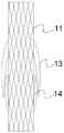
图1a和图1b为根据本申请实施例的主动脉瓣支架的示意图;1a and 1b are schematic diagrams of an aortic valve stent according to an embodiment of the present application;

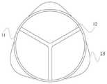
图2为根据本申请实施例的主动脉瓣支架的瓣膜示意图;2 is a schematic diagram of a valve of an aortic valve stent according to an embodiment of the present application;

图3为根据本申请实施例的主动脉瓣支架被固定于主动脉瓣处的示意图;3 is a schematic diagram of the aortic valve stent being fixed at the aortic valve according to an embodiment of the present application;

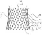
图4a和图4b为根据本申请另一实施例的主动脉瓣支架及其使用状态的示意图;4a and 4b are schematic diagrams of an aortic valve stent and a use state thereof according to another embodiment of the present application;

图5为根据本申请又一实施例的主动脉瓣支架的使用状态示意图;5 is a schematic diagram of a use state of an aortic valve stent according to another embodiment of the present application;

图6为根据本申请再一实施例的主动脉瓣支架的示意图;6 is a schematic diagram of an aortic valve stent according to yet another embodiment of the present application;

图7为根据本申请再一实施例的主动脉瓣支架的示意图;7 is a schematic diagram of an aortic valve stent according to yet another embodiment of the present application;

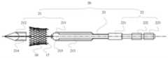
图8a-图8e为根据本申请实施例的用于输送主动脉瓣的系统将所装载的主动脉瓣支架释放的示意图;8a-8e are schematic diagrams of releasing a loaded aortic valve stent by a system for delivering an aortic valve according to an embodiment of the present application;

图9a-图9b为根据本申请实施例的用于输送主动脉瓣的系统在主动脉瓣处将主动脉瓣支架释放的示意图;9a-9b are schematic diagrams of releasing an aortic valve stent at the aortic valve by a system for delivering an aortic valve according to an embodiment of the present application;

图10a和图10b为根据本申请另一实施例的用于输送主动脉瓣的系统的示意图。10a and 10b are schematic diagrams of a system for delivering an aortic valve according to another embodiment of the present application.

具体实施方式Detailed ways

为使本申请的目的、技术方案和优点更加清楚,下面将结合本申请实施例的附图,对本申请的技术方案进行清楚、完整地描述。显然,所描述的实施例是本申请的一个实施例,而不是全部的实施例。基于所描述的本申请的实施例,本领域普通技术人员在无需创造性劳动的前提下所获得的所有其他实施例,都属于本申请保护的范围。In order to make the purpose, technical solutions and advantages of the present application clearer, the technical solutions of the present application will be described clearly and completely below with reference to the accompanying drawings of the embodiments of the present application. Obviously, the described embodiment is one embodiment of the present application, but not all embodiments. Based on the described embodiments of the present application, all other embodiments obtained by those of ordinary skill in the art without creative work fall within the protection scope of the present application.

需要说明的是,除非另外定义,本申请使用的技术术语或者科学术语应当为本申请所属领域内具有一般技能的人士所理解的通常意义。若全文中涉及“第一”、“第二”等描述,则该“第一”、“第二”等描述仅用于区别类似的对象,而不能理解为指示或暗示其相对重要性、先后次序或者隐含指明所指示的技术特征的数量,应该理解为“第一”、“第二”等描述的数据在适当情况下可以互换。若全文中出现“和/或”,其含义为包括三个并列方案,以“A和/或B”为例,包括A方案,或B方案,或A和B同时满足的方案。It should be noted that, unless otherwise defined, the technical terms or scientific terms used in the present application shall have the usual meanings understood by those with ordinary skills in the field to which the present application belongs. If descriptions such as "first" and "second" are involved in the whole text, the descriptions such as "first" and "second" are only used to distinguish similar objects, and should not be construed as indicating or implying their relative importance, sequence, etc. The order or the quantity of the indicated technical features is implicitly indicated, and it should be understood that the data described by "first", "second", etc. can be interchanged under appropriate circumstances. If "and/or" appears in the whole text, it means that it includes three parallel schemes. Taking "A and/or B" as an example, it includes scheme A, scheme B, or scheme that A and B satisfy at the same time.

根据本申请实施例的第一个方面,提供一种主动脉瓣支架10,参照图1a-图3,主动脉瓣支架10包括支架本体11,支架本体11具有收缩状态和展开状态,支架本体11能够在收缩状态下被输送,并在到达主动脉瓣后被切换为展开状态;设置于支架本体11内侧的瓣膜12;以及设置于支架本体11外侧的第一定位部13和第二定位部14,当支架本体11处于展开状态时,第一定位部13和第二定位部14能够分别位于主动脉瓣的瓣叶的两侧,以将支架本体11固定于主动脉瓣处。According to a first aspect of the embodiments of the present application, anaortic valve stent 10 is provided. Referring to FIGS. 1 a to 3 , theaortic valve stent 10 includes astent body 11 , thestent body 11 has a contracted state and an expanded state, and thestent body 11 Thevalve 12 can be delivered in a contracted state and switched to a deployed state after reaching the aortic valve; thevalve 12 provided inside thestent body 11 ; and thefirst positioning portion 13 and thesecond positioning portion 14 provided on the outside of thestent body 11 , when thestent body 11 is in the deployed state, thefirst positioning portion 13 and thesecond positioning portion 14 can be respectively located on both sides of the valve leaflet of the aortic valve, so as to fix thestent body 11 at the aortic valve.

图1a示出的是支架本体11在展开状态下的结构,图1b示出的是支架本体11在收缩状态下的结构。支架本体11可以为网格组成的筒状结构,网格可以为图中示出的菱形状或者其他不规则的形状,例如四条弧形边围成的类菱形状结构等,菱形状结构的好处在于易于支架本体11的收缩和展开。在收缩状态下,支架本体11的菱形网格结构可以被压缩,从而减小支架本体11的直径,使主动脉瓣支架10能够被装载到输送装置中,输送装置可以是本领域中常用的经导管输送装置。输送装置将主动脉瓣支架10输送到主动脉瓣后,支架本体11可以切换成展开状态,从而被固定在主动脉瓣处。FIG. 1a shows the structure of thestent body 11 in the unfolded state, and FIG. 1b shows the structure of thestent body 11 in the contracted state. Thestent body 11 can be a cylindrical structure composed of a grid, and the grid can be a rhombus shape as shown in the figure or other irregular shapes, such as a rhombus-like structure surrounded by four arc-shaped sides, etc. The advantages of the rhombus-shaped structure The purpose is to facilitate the retraction and deployment of thestent body 11 . In the collapsed state, the rhombic mesh structure of thestent body 11 can be compressed, thereby reducing the diameter of thestent body 11, so that theaortic valve stent 10 can be loaded into a delivery device, which can be a conventional transfusion device commonly used in the art. Catheter delivery device. After theaortic valve stent 10 is delivered to the aortic valve by the delivery device, thestent body 11 can be switched to a deployed state so as to be fixed at the aortic valve.

在一些实施例中,支架本体11可以为镍钛合金材料制成,镍钛合金在较低的温度下具有一定的柔性,可以使用冰水等为支架本体11进行降温,使其更容易被压缩成收缩状态并装载到输送装置中。当主动脉瓣支架10被输送到主动脉瓣处以后,输送装置可以将主动脉瓣支架10释放,由于人体内的温度相对较高,支架本体11在这样的温度下柔性降低,从而能够较为快速的自行膨胀,方便主动脉瓣支架10的固定。在一些其他的实施例中,本领域技术人员也可以采用其他类型的记忆合金或者其他任何合适的材料来制作支架本体,对此不作具体的限定。In some embodiments, thestent body 11 can be made of a nickel-titanium alloy material, which has a certain flexibility at lower temperatures, and ice water can be used to cool thestent body 11 to make it easier to compress retracted and loaded into the conveyor. After theaortic valve stent 10 is delivered to the aortic valve, the delivery device can release theaortic valve stent 10. Since the temperature in the human body is relatively high, the flexibility of thestent body 11 decreases at such a temperature, so that thestent body 11 can be more quickly Self-expanding to facilitate the fixation of theaortic valve stent 10 . In some other embodiments, those skilled in the art can also use other types of memory alloys or any other suitable materials to make the stent body, which is not specifically limited.

支架本体11的直径可以根据患者的主动脉的内径来确定,使得支架本体11的顶端能够抵持于主动脉壁上,与第一定位部13和第二定位部14来共同地对支架本体11进行固定。The diameter of thestent body 11 can be determined according to the inner diameter of the aorta of the patient, so that the top end of thestent body 11 can abut against the aortic wall, and together with thefirst positioning portion 13 and thesecond positioning portion 14, thestent body 11 is aligned. to be fixed.

图2示出了主动脉瓣支架10的内部结构,支架本体11的内侧设置有瓣膜12,瓣膜12通常包括3个瓣叶,瓣膜12可以用于实现主动脉瓣的功能,具体地,当左心室收缩时,瓣叶在血流的冲击下将会上升,瓣叶之间出现间隙,使得左心室中的血液能够被泵入主动脉中,左心室舒张时,瓣叶会下降,瓣叶之间沿着接合缘对合,防止主动脉中的血液反流进入左心室。Fig. 2 shows the internal structure of theaortic valve stent 10. The inner side of thestent body 11 is provided with avalve 12. Thevalve 12 usually includes three valve leaflets. Thevalve 12 can be used to realize the function of the aortic valve. When the ventricle contracts, the valve leaflets will rise under the impact of blood flow, and there will be gaps between the valve leaflets, so that the blood in the left ventricle can be pumped into the aorta. They meet along the commissure border, preventing the backflow of blood in the aorta into the left ventricle.

瓣膜12可以被缝制在支架本体11上,在一些实施例中,瓣膜12靠近支架本体11的一端可以形成有裙边,裙边可以增加瓣膜12与支架本体11的接触面积,从而能够更好地将瓣膜12与支架本体11进行固定,防止瓣膜12意外脱落。Thevalve 12 can be sewn on thestent body 11. In some embodiments, a skirt can be formed at one end of thevalve 12 close to thestent body 11, and the skirt can increase the contact area between thevalve 12 and thestent body 11, so that thevalve 12 can be better Thevalve 12 and thestent body 11 are fixed to prevent thevalve 12 from falling off accidentally.

在一些实施例中,瓣膜12可以由猪心包、牛心包、马心包等制成,在一些其他的实施例中,瓣膜12还可以由其他合适的仿生材料制成,例如高分子材料聚四氟乙烯或者涤纶布等,对此不作具体的限定。In some embodiments, thevalve 12 can be made of porcine pericardium, bovine pericardium, horse pericardium, etc. In some other embodiments, thevalve 12 can also be made of other suitable biomimetic materials, such as polymer material polytetrafluoroethylene Vinyl or polyester cloth, etc., are not specifically limited.

参照图1a和图3,支架本体11的外侧设置有第一定位部13和第二定位部14,第一定位部13和第二定位部14可以以缝合的方式被固定在支架本体11上,或者被焊接在支架本体11上,本领域技术人员也可以使用其他合适的方式将第一定位部13和第二定位部14固定在支架本体11上,对此不作具体的限定。1a and 3, the outer side of thebracket body 11 is provided with afirst positioning portion 13 and asecond positioning portion 14, and thefirst positioning portion 13 and thesecond positioning portion 14 can be fixed on thebracket body 11 by sewing, Or welded on thebracket body 11 , those skilled in the art can also use other suitable methods to fix thefirst positioning portion 13 and thesecond positioning portion 14 on thebracket body 11 , which is not specifically limited.

如图3示出的,当主动脉瓣支架10被设置在主动脉瓣处时,第一定位部13和第二定位部14将会分别位于主动脉瓣的瓣叶的两侧,具体地,在每个主动脉瓣的瓣叶后面,主动脉壁会向外膨出,在主动脉瓣的瓣叶与主动脉壁之间形成主动脉窦,第一定位部13将会位于主动脉窦中,此时,第一定位部13的主体将会抵持在主动脉瓣的瓣叶上,底部将会抵持在主动脉窦的底部,这有利于在释放主动脉瓣支架10的过程中进行定位。第二定位部14将会位于主动脉瓣的瓣叶背离主动脉壁的一侧并抵持在主动脉瓣的瓣叶上,从而,与第一定位部13形成配合,将主动脉瓣支架10固定。As shown in FIG. 3 , when theaortic valve stent 10 is disposed at the aortic valve, thefirst positioning portion 13 and thesecond positioning portion 14 will be located on both sides of the valve leaflet of the aortic valve, specifically, at the Behind the valve leaflet of each aortic valve, the aortic wall will bulge outward, and an aortic sinus will be formed between the valve leaflet of the aortic valve and the aortic wall, and thefirst positioning portion 13 will be located in the aortic sinus, At this time, the main body of thefirst positioning portion 13 will bear against the leaflet of the aortic valve, and the bottom will bear against the bottom of the aortic sinus, which is beneficial for positioning during the release of theaortic valve stent 10 . Thesecond positioning portion 14 will be located on the side of the aortic valve leaflet away from the aortic wall and abut against the valve leaflet of the aortic valve, so as to form cooperation with thefirst positioning portion 13 to attach theaortic valve stent 10 to the aortic valve. fixed.

第一定位部13和第二定位部14的数量与主动脉瓣的瓣叶数量相适应,即,通常设置有3个第一定位部13和3个第二定位部14,在一些实施例中,针对只有2个主动脉瓣瓣叶的患者,也可以仅设置2个第一定位部13和2个第二定位部14。在一些实施例中,第一定位部13和第二定位部14的数量也可以与主动脉瓣的瓣叶的数量不相同,这样的实施例将会在下文的相关部分处进行详细的描述。The number of thefirst positioning portion 13 and thesecond positioning portion 14 is adapted to the number of leaflets of the aortic valve, that is, there are usually threefirst positioning portions 13 and threesecond positioning portions 14, in some embodiments , for a patient with only two aortic valve leaflets, only two first positioningportions 13 and twosecond positioning portions 14 may be provided. In some embodiments, the number of thefirst positioning portion 13 and thesecond positioning portion 14 may also be different from the number of leaflets of the aortic valve, and such embodiments will be described in detail in the relevant sections below.

在本实施例中,主动脉瓣会被夹持在第一定位部13和第二定位部14之间,从而,既能够避免左心室收缩时主动脉瓣支架10在左心室中血液的冲击下向上移位,也能够避免左心室舒张时主动脉瓣支架10在主动脉中血液的冲击下向下移位,获得更好的固定效果。In this embodiment, the aortic valve is clamped between thefirst positioning portion 13 and thesecond positioning portion 14, so that theaortic valve stent 10 can be prevented from being impacted by the blood in the left ventricle when the left ventricle contracts. The upward displacement can also avoid the downward displacement of theaortic valve stent 10 under the impact of the blood in the aorta when the left ventricle is diastolic, so as to obtain a better fixation effect.

在一些实施例中,仍然参照图1a和图1b,第一定位部13和第二定位部14可以设置成圆弧状,从而,既能够使得第一定位部13和第二定位部14拥有较大的接触面积,获得更好的固定效果,又能够尽可能的减小主动脉瓣支架10的体积。In some embodiments, still referring to FIG. 1a and FIG. 1b, thefirst positioning portion 13 and thesecond positioning portion 14 may be arranged in a circular arc shape, so that thefirst positioning portion 13 and thesecond positioning portion 14 can have relatively The larger contact area can obtain better fixation effect, and can reduce the volume of theaortic valve stent 10 as much as possible.

在一些实施例中,参照图1b,在支架本体11处于收缩状态时,第一定位部13可以至少部分地位于第二定位部14的外侧,具体地,第一定位部13的末端和第二定位部14的末端将会发生一定的重叠,并且,第一定位部13的末端在第二定位部14的末端外侧。从而,在将主动脉瓣支架10释放的过程中,第一定位部13可以先于第二定位部14张开,进而可以先将第一定位部13底部定位在主动脉瓣的窦底,再使第二定位部14张开完成对主动脉瓣的夹持,方便进行操作。并且,这样的重叠使得第一定位部13和第二定位部14在对主动脉瓣的瓣叶进行夹持时能够相互配合,起到更好的固定效果。In some embodiments, referring to FIG. 1b, when thestent body 11 is in a retracted state, thefirst positioning portion 13 may be at least partially located outside thesecond positioning portion 14, specifically, the end of thefirst positioning portion 13 and thesecond positioning portion 13 The ends of thepositioning portion 14 will overlap to a certain extent, and the end of thefirst positioning portion 13 is outside the end of thesecond positioning portion 14 . Therefore, in the process of releasing theaortic valve stent 10, thefirst positioning portion 13 can be opened before thesecond positioning portion 14, and then the bottom of thefirst positioning portion 13 can be positioned at the sinus bottom of the aortic valve, and then Thesecond positioning portion 14 is opened to complete the clamping of the aortic valve, which is convenient for operation. Moreover, such overlapping enables thefirst positioning portion 13 and thesecond positioning portion 14 to cooperate with each other when clamping the valve leaflet of the aortic valve, thereby achieving a better fixing effect.

在一些实施例中,参照图4a和图4b,第一定位部13远离支架本体11的一端朝向支架本体11弯折形成第一钩状体131,第二定位部14远离所述支架本体11的一端背离支架本体11弯折形成第二钩状体141,第一钩状体131和第二钩状体141能够相互配合以将主动脉瓣的瓣叶夹持于第一定位部13和第二定位部14之间。In some embodiments, referring to FIGS. 4 a and 4 b , one end of thefirst positioning portion 13 away from thebracket body 11 is bent toward thebracket body 11 to form a first hook-shapedbody 131 , and thesecond positioning portion 14 is away from thebracket body 11 . One end is bent away from thestent body 11 to form a second hook-shapedbody 141. The first hook-shapedbody 131 and the second hook-shapedbody 141 can cooperate with each other to clamp the leaflet of the aortic valve to thefirst positioning part 13 and the second hook-shapedbody 141. between thepositioning parts 14 .

具体地,参照图4b,在这样的实施例中,第一钩状体131的弯折部分将会抵持在主动脉瓣的窦底,并且第一钩状体131的末端将会抵持在主动脉瓣的瓣叶上。第二钩状体141的弯折部分会推动主动脉瓣的瓣叶末端形成一定的卷曲并进入第一钩状体131和第二钩状体141之间的位置,并且,第二钩状体141的末端将会抵持在主动脉瓣的瓣叶上。由此,对主动脉瓣的瓣叶形成了更加稳固的夹持。Specifically, referring to FIG. 4b, in such an embodiment, the bent portion of the first hook-shapedbody 131 will abut against the sinus floor of the aortic valve, and the distal end of the first hook-shapedbody 131 will abut against the sinus floor of the aortic valve. on the leaflets of the aortic valve. The bent portion of the second hook-shapedbody 141 will push the leaflet end of the aortic valve to form a certain curl and enter the position between the first hook-shapedbody 131 and the second hook-shapedbody 141, and the second hook-shaped body The tip of 141 will rest against the leaflets of the aortic valve. Thereby, a more stable clamping of the leaflets of the aortic valve is formed.

在这样的实施例中,本领域技术人员可以合理地设置第一钩状体131和第二钩状体141的弯折部分的角度,以及第一定位部13和第二定位部14在支架本体11打开状态下与支架本体11之间形成的夹角,从而获得期望的夹持效果。在一些实施例中,优选地,第一定位部13在支架本体11展开状态下与支架本体11之间形成的夹角为30-70度。In such an embodiment, those skilled in the art can reasonably set the angles of the bent portions of the first hook-shapedbody 131 and the second hook-shapedbody 141, and thefirst positioning portion 13 and thesecond positioning portion 14 in the bracket body. 11 and thebracket body 11 in the open state, so as to obtain the desired clamping effect. In some embodiments, preferably, the included angle formed between thefirst positioning portion 13 and thestent body 11 in the unfolded state of thestent body 11 is 30-70 degrees.

在一些实施例中,当支架本体11处于收缩状态时,第一定位部13和第二定位部14可以为平直状态,例如,可以在输送系统的鞘壁所压迫而变为平直状态,此时,第一钩状体131和第二钩状体141由于被压平而消失,当支架本体11被释放后,第一定位部13和第二定位部14被弹出,并且,由于失去了压迫,第一定位部13和第二定位部14的末端弯折而重新形成第一钩状体131和第二钩状体141。本领域技术人员可以使用例如记忆合金等材料来实现上述效果,对此不作具体的限制。这样的实施例可以减小支架本体11在收缩状态时主动脉瓣支架10整体的直径,方便进行装载和释放。In some embodiments, when thestent body 11 is in a retracted state, thefirst positioning portion 13 and thesecond positioning portion 14 may be in a straight state, for example, may be pressed into a straight state by the sheath wall of the delivery system, At this time, the first hook-shapedbody 131 and the second hook-shapedbody 141 disappear due to being flattened, and when thebracket body 11 is released, thefirst positioning portion 13 and thesecond positioning portion 14 are ejected, and due to the lost Under pressure, the ends of thefirst positioning portion 13 and thesecond positioning portion 14 are bent to form the first hook-shapedbody 131 and the second hook-shapedbody 141 again. Those skilled in the art can use materials such as memory alloys to achieve the above effects, which are not specifically limited. Such an embodiment can reduce the overall diameter of theaortic valve stent 10 when thestent body 11 is in a contracted state, so as to facilitate loading and release.

设置第一钩状体131和第二钩状体141的一个好处在于,第一钩状体131和第二钩状体141相互配合能够对主动脉瓣的瓣叶形成更加稳固的夹持,进一步防止了主动脉瓣支架10的移位。尤其是对于一些主动脉瓣反流的患者而言,其主动脉瓣的瓣叶上没有钙化灶,相对较为柔软,使用相关技术中所提供的其他的方式可能难以保证主动脉瓣支架的位置的稳定。并且,在进行释放的过程中,可能需要使第一定位部13沿着主动脉壁进行滑动,相较于直线条型设计的第一定位部13而言,设置第一钩状体131还能够使得第一定位部13较为尖锐的部分不会直接接触到主动脉壁,避免造成损伤。One advantage of arranging the first hook-shapedbody 131 and the second hook-shapedbody 141 is that the mutual cooperation of the first hook-shapedbody 131 and the second hook-shapedbody 141 can form a more stable clamping for the valve leaflet of the aortic valve, furthermore Displacement of theaortic valve stent 10 is prevented. Especially for some patients with aortic valve regurgitation, the aortic valve leaflets are relatively soft without calcification, and it may be difficult to ensure the position of the aortic valve stent by using other methods provided in the related art. Stablize. In addition, in the process of releasing, it may be necessary to make thefirst positioning portion 13 slide along the aortic wall. Compared with thefirst positioning portion 13 with a linear design, the provision of the first hook-shapedbody 131 can also Therefore, the relatively sharp part of thefirst positioning portion 13 will not directly contact the aortic wall, so as to avoid damage.

如上文中所描述的,第一定位部13和第二定位部14的数量可以与主动脉瓣瓣叶的数量相适应。由于第一钩状体131和第二钩状体141对瓣叶形成的夹持十分稳固,在夹持形成后难以再次调整第一钩状体131和第二钩状体141夹持的位置。而在实际应用的过程中,通常希望主动脉瓣支架10能够与主动脉保证较好的同轴性(主动脉瓣支架10的轴线与主动脉管腔的轴线大致重合),如果主动脉瓣支架10斜行放置,将可能会导致瓣周漏等严重的并发症。如果在每一个第一定位部13和第二定位部14上均设置第一钩状体131和第二钩状体141,则可能需要操作者在实际释放主动脉瓣支架10的过程中,在第一定位部13被释放之前或者被释放并张开后消耗较多的时间来调整好角度后再进行第二定位部14的释放,以使得最终完成释放后的主动脉瓣支架10与主动脉之间能够保证较好的同轴性。As described above, the number of thefirst positioning portion 13 and thesecond positioning portion 14 may be adapted to the number of the aortic valve leaflets. Since the first hook-shapedbody 131 and the second hook-shapedbody 141 hold the valve leaflet very firmly, it is difficult to adjust the clamping position of the first hook-shapedbody 131 and the second hook-shapedbody 141 again after the clamping is formed. In practical application, it is generally desirable that theaortic valve stent 10 can ensure good coaxiality with the aorta (the axis of theaortic valve stent 10 is approximately coincident with the axis of the aortic lumen). 10 Oblique placement may lead to serious complications such as paravalvular leakage. If the first hook-shapedbody 131 and the second hook-shapedbody 141 are provided on each of thefirst positioning part 13 and thesecond positioning part 14 , the operator may be required to Before thefirst positioning portion 13 is released or after being released and opened, it takes a long time to adjust the angle before releasing thesecond positioning portion 14, so that the releasedaortic valve stent 10 and the aorta are finally completed. Good coaxiality can be ensured between them.

基于此,在一些实施例中,可以仅在部分第一定位部13和第二定位部14上设置第一钩状体131和第二钩状体141,例如仅在对应的一个第一定位部13和一个第二定位部14上设置第一钩状体131和第二钩状体141,而另一部分第一定位部13和第二定位部14可以设置成例如上文中所描述的圆弧状。Based on this, in some embodiments, the first hook-shapedbody 131 and the second hook-shapedbody 141 may be provided only on part of thefirst positioning part 13 and thesecond positioning part 14 , for example, only on one corresponding first positioningpart 13 and onesecond positioning part 14 are provided with a first hook-shapedbody 131 and a second hook-shapedbody 141, while the other part of thefirst positioning part 13 and thesecond positioning part 14 can be arranged in the arc shape as described above. .

或者,可以不必在每个瓣叶处都设置第一定位部13和第二定位部14,例如,仅在一个瓣叶处设置第一定位部13和第二定位部14,并在该第一定位部13和第二定位部14上设置第一钩状体131和第二钩状体141,在这样的实施例中,在第一钩状体131和第二钩状体141对一个瓣叶已经形成了十分稳固的夹持后,如果主动脉瓣支架10与主动脉之间的同轴性并不良好,则会产生一定的扭矩,使得主动脉瓣支架10没有设置第一定位部13和第二定位部14的一侧,或者仅设置第一定位部13和第二定位部14而没有设置第一钩状体131和第二钩状体141的一侧能够在该扭矩的作用下进行一定的移动,实现自动的摆正,由此,操作人员在释放主动脉瓣支架10的过程中可以迅速完成主动脉瓣支架的定位,无需消耗较长的时间来进行角度的调整。Alternatively, it is not necessary to provide thefirst positioning portion 13 and thesecond positioning portion 14 at each leaflet. For example, thefirst positioning portion 13 and thesecond positioning portion 14 are provided at only one leaflet, and thefirst positioning portion 13 and thesecond positioning portion 14 are provided at the first valve leaflet. The positioningportion 13 and thesecond positioning portion 14 are provided with a first hook-shapedbody 131 and a second hook-shapedbody 141. In such an embodiment, the first hook-shapedbody 131 and the second hook-shapedbody 141 correspond to one leaflet. After a very stable clamping has been formed, if the coaxiality between theaortic valve stent 10 and the aorta is not good, a certain torque will be generated, so that theaortic valve stent 10 is not provided with thefirst positioning portion 13 and the aorta. The side of thesecond positioning portion 14 , or the side where only thefirst positioning portion 13 and thesecond positioning portion 14 are provided without the first hook-shapedbody 131 and the second hook-shapedbody 141 can perform under the action of the torque. A certain movement realizes automatic alignment, thus, the operator can quickly complete the positioning of the aortic valve stent during the process of releasing theaortic valve stent 10, and does not need to spend a long time to adjust the angle.

进一步地,本实施例中,设置第一钩状体131和第二钩状体141还存在另一个好处。图5中左侧部分示出了一种相关技术中的主动脉瓣支架设置在主动脉瓣处的示意图,可以理解地,主动脉窦的上方形成有冠脉开口,相关技术中的主动脉瓣支架被设置在主动脉瓣的瓣叶的内侧,从而主动脉瓣的瓣叶在主动脉瓣支架的挤压作用下将会贴在主动脉的壁上,而如果患者的冠脉开口较低,和/或主动脉瓣的瓣叶较长,则可能会导致冠脉开口被瓣叶阻挡。Further, in this embodiment, there is another advantage of disposing the first hook-shapedbody 131 and the second hook-shapedbody 141 . The left part of FIG. 5 shows a schematic diagram of an aortic valve stent disposed at the aortic valve in the related art. It can be understood that a coronary opening is formed above the aortic sinus, and the aortic valve in the related art The stent is placed inside the leaflets of the aortic valve, so that the leaflets of the aortic valve will stick to the wall of the aorta under the compression of the aortic valve stent, and if the patient's coronary opening is low, and/or the aortic valve has long leaflets, which may cause the coronary opening to be blocked by the leaflets.

而在本实施例中,参照图5中右侧部分,主动脉瓣的瓣叶将会被限制在第一钩状体131和第二钩状体141之间形成的间隙中,而不是紧贴主动脉壁,从而,避免了主动脉瓣的瓣叶对冠脉开口形成遮挡。在一些实施例中,为了进一步地避免对冠脉开口形成遮挡,可以使第一定位部13在支架本体11处于打开状态时,与支架本体11之间形成一个较大的夹角,例如,形成一个30-70度的夹角。In this embodiment, referring to the right part in FIG. 5 , the leaflets of the aortic valve will be confined in the gap formed between the first hook-shapedbody 131 and the second hook-shapedbody 141 , instead of being in close contact The aortic wall, thus, avoids occlusion of the coronary opening by the leaflets of the aortic valve. In some embodiments, in order to further avoid blocking the coronary artery opening, when thestent body 11 is in the open state, thefirst positioning portion 13 may form a relatively large angle with thestent body 11 , for example, forming An included angle of 30-70 degrees.

在一些实施例中,仍可参照图4a和图4b,第一钩状体131的末端形成有第一刺状体132,和/或第二钩状体141的末端形成有第二刺状体142,第一刺状体132和第二刺状体142能够至少部分地刺入主动脉瓣的瓣叶中,从而能够进一步地提高夹持的稳定性。In some embodiments, still referring to FIG. 4a and FIG. 4b, the end of the first hook-shapedbody 131 is formed with a first spine-shapedbody 132, and/or the end of the second hook-shapedbody 141 is formed with a second spine-shapedbody 142, the first thorn-shapedbody 132 and the second thorn-shapedbody 142 can at least partially penetrate into the valve leaflets of the aortic valve, so as to further improve the stability of clamping.

在一些实施例中,第一刺状体132和/或第二刺状体142上可以形成有倒刺,以使得第一刺状体132和第二刺状体142刺入主动脉瓣的瓣叶后难以滑出,进一步提高夹持的稳定性。In some embodiments, barbs may be formed on thefirst spines 132 and/or thesecond spines 142 such that thefirst spines 132 and thesecond spines 142 penetrate the valve of the aortic valve It is difficult to slide out the back of the leaf, which further improves the stability of clamping.

在一些实施例中,第一钩状体131和第二钩状体141上可以设置有相互吸引的磁性件,或者,第一刺状体132和第二刺状体142上可以设置有相互吸引的磁性件,该磁性件能够使得第一钩状体131和第二钩状体141在释放过程中在相互吸引的作用下朝向彼此移动,更加容易地形成对主动脉瓣瓣叶的夹持,并且,在形成夹持后能够较为稳定的保持该夹持状态。In some embodiments, the first hook-shapedbody 131 and the second hook-shapedbody 141 may be provided with magnetic members that attract each other, or the first and second spine-shapedbodies 132 and 142 may be provided with mutually attractive magnetic elements. The magnetic member can make the first hook-shapedbody 131 and the second hook-shapedbody 141 move towards each other under the action of mutual attraction during the release process, so as to form the clamping of the aortic valve leaflet more easily, Moreover, after the clamping is formed, the clamping state can be maintained relatively stably.

在一些实施例中,参照图6,主动脉瓣支架10还包括牵引丝15,牵引丝15能够穿过第二钩状体141并连接于第一钩状体131,从而,该牵引丝15能够牵引第一钩状体131朝向第二钩状体141运动。In some embodiments, referring to FIG. 6 , theaortic valve stent 10 further includes atraction wire 15 , which can pass through thesecond hook body 141 and be connected to thefirst hook body 131 , so that thetraction wire 15 can The first hook-shapedbody 131 is pulled to move toward the second hook-shapedbody 141 .

具体地,尽管第一钩状体131和第二钩状体141之间的本身是相互配合设置的,但是在实际释放的过程中,由于每个患者的瓣叶大小、厚度等均不相同,所形成的夹持效果可能不够稳定,例如,夹持的不够紧密。为此,本实施例中,设置了牵引丝15,牵引丝15的一端可以穿过第二钩状体141(此处的穿过是指牵引丝15可以穿过第二钩状体141的某一个部位,并可以与第二钩状体141之间进行相对滑动)和第一钩状体131,从而,在完成了第一钩状体131和第二钩状体141的释放后,可以通过操作牵引丝15(例如通过输送装置来进行操作)的两端来使得第一钩状体131朝向第二钩状体141进行运动,以实现更加紧密的夹持。可以理解地,在第一钩状体131朝向第二钩状体141运动实现了足够紧密的夹持后,可以停止对牵引丝15的操作,即使失去了牵引丝15的作用力也并不会导致第一钩状体131和第二钩状体141之间再次发生位移而影响夹持效果。进一步地,在牵引结束后,可以通过操作牵引丝15的一端来将牵引丝15拉出患者体内。Specifically, although the first hook-shapedbody 131 and the second hook-shapedbody 141 are arranged in cooperation with each other, in the actual release process, since the size and thickness of the valve leaflets of each patient are different, The resulting clamping effect may not be stable enough, eg, not tightly clamped. To this end, in this embodiment, a pullingwire 15 is provided, and one end of the pullingwire 15 can pass through the second hook-shaped body 141 (the passing through here means that the pullingwire 15 can pass through a certain part of the second hook-shaped body 141 ). one part, and can slide relative to the second hook-shaped body 141) and the first hook-shapedbody 131, so that after the release of the first hook-shapedbody 131 and the second hook-shapedbody 141 is completed, the Both ends of the pull wire 15 (eg, by a delivery device) are manipulated to move thefirst hook 131 toward thesecond hook 141 to achieve a tighter grip. It can be understood that after the first hook-shapedbody 131 moves toward the second hook-shapedbody 141 to achieve a sufficiently tight clamping, the operation of thetraction wire 15 can be stopped, and even if the force of thetraction wire 15 is lost, it will not cause Displacement occurs again between the first hook-shapedbody 131 and the second hook-shapedbody 141 to affect the clamping effect. Further, after the pulling ends, the pullingwire 15 can be pulled out of the patient's body by operating one end of the pullingwire 15 .

在一些实施例中,牵引丝15可以被配置成能够在牵引第一钩状体131朝向第二钩状体141进行运动的过程中,至少部分地切割被夹持于第一钩状体131和第二钩状体141之间的主动脉瓣的瓣叶。可以理解地,在第一钩状体131和第二钩状体141被释放后,牵引丝15将会处于主动脉瓣的瓣叶的末端的位置,可以将牵引丝15设置成具有足够的强度,使得牵引丝15在对第一钩状体131进行牵引的过程中,可以从主动脉瓣的瓣叶末端起对主动脉瓣的瓣叶进行切割,以进一步地保证主动脉瓣的瓣叶不会对冠脉开口形成遮挡。In some embodiments, the pullingwire 15 may be configured to at least partially cut the clamped first hook-shapedbody 131 and the second hook-shapedbody 141 during the movement of the pulling the first hook-shapedbody 131 toward the second hook-shapedbody 141 The leaflets of the aortic valve between the second hooks 141 . It can be understood that after the first hook-shapedbody 131 and the second hook-shapedbody 141 are released, the pullingwire 15 will be at the position of the distal end of the leaflet of the aortic valve, and the pullingwire 15 can be set to have sufficient strength , so that in the process of pulling the first hook-shapedbody 131, the pullingwire 15 can cut the leaflets of the aortic valve from the end of the leaflets of the aortic valve, so as to further ensure that the leaflets of the aortic valve are not It will block the coronary opening.

在一些实施例中,第一定位部13和第二定位部14与主动脉瓣的瓣叶接触的位置可以设置有磨砂层,该磨砂层可以增加第一定位部13和第二定位部14与主动脉瓣的瓣叶之间的摩擦力,进一步地防止主动脉瓣支架10的移位。本领域技术人员可以根据实际情况来确定磨砂层设置的位置,对此不作限制。In some embodiments, the position where thefirst positioning part 13 and thesecond positioning part 14 are in contact with the leaflets of the aortic valve may be provided with a frosted layer, and the frosted layer may increase the relationship between thefirst positioning part 13 and thesecond positioning part 14 The frictional force between the leaflets of the aortic valve further prevents displacement of theaortic valve stent 10 . Those skilled in the art can determine the location of the frosted layer according to the actual situation, which is not limited.

需要注意的是,在一些实施例中,参照图5,在释放主动脉瓣支架10的过程中,可能需要使得第一定位部13顺着主动脉壁进行上下滑动以进行位置的调整,因此,第一定位部13上与主动脉壁发生接触的位置,即开始卷曲的位置,不能被设置磨砂层(即使该位置在后续可能与主动脉瓣的瓣叶接触),以方便操作人员进行操作。It should be noted that, in some embodiments, referring to FIG. 5 , in the process of releasing theaortic valve stent 10, it may be necessary to make thefirst positioning part 13 slide up and down along the aortic wall to adjust the position. Therefore, The position of thefirst positioning portion 13 in contact with the aortic wall, that is, the position where the crimping begins, cannot be provided with a frosted layer (even if the position may be in contact with the aortic valve leaflet in the future), so as to facilitate the operator to operate.

在一些实施例中,仍可参照图5,支架本体11可以包括收缩段111和设置在收缩段两端的扩张段112,其中,扩张段112的内径在背离收缩段111的方向上逐渐增大。即,支架本体11可以是本领域的相关技术中所使用的拥有较长的本体的主动脉瓣支架,其中,收缩段111为本体中间的内径较小的部分,而扩张段112是连接在收缩段111上方和下方的内径逐渐增大的部分,收缩段111和扩展段112可以是一体成型的,本领域技术人员可以参照本领域的相关技术来具体设置扩张段112和收缩段111的长度、内径以及连接方式,对此不作具体的限制。In some embodiments, still referring to FIG. 5 , thestent body 11 may include acontraction section 111 and anexpansion section 112 disposed at both ends of the contraction section, wherein the inner diameter of theexpansion section 112 gradually increases in a direction away from thecontraction section 111 . That is, thestent body 11 may be an aortic valve stent with a longer body used in the related art in the art, wherein the constrictedsection 111 is a part with a smaller inner diameter in the middle of the body, and the dilatedsection 112 is connected to the constricted section The inner diameter of the portion above and below thesegment 111 that gradually increases, thecontraction segment 111 and theexpansion segment 112 can be integrally formed, and those skilled in the art can refer to the relevant technology in the field to specifically set the lengths of theexpansion segment 112 and thecontraction segment 111, There are no specific restrictions on the inner diameter and connection method.

在本实施例中,瓣膜12和第一定位部13可以设置在收缩段111,从而,参照图4b,收缩段111位于瓣膜12和第一定位部13上方的一段将不会存在任何的遮挡,血液可以经由该位置顺利地流入冠脉开口。In this embodiment, thevalve 12 and thefirst positioning part 13 can be arranged on the constrictedsection 111, so, referring to FIG. Blood can flow smoothly into the coronary opening via this location.

在一些实施例中,参照图7,主动脉瓣支架10还可以包括设置于支架本体11中部的收缩环16,收缩环16会在支架本体11处于展开状态时对支架本体11的中部进行收缩,使得支架本体11中部的直径小于两端的直径。本实施例中,由于支架本体11的中部被收缩环16收缩,会进一步地带动被第一定位部13和第二定位部14所夹持的主动脉瓣远离主动脉壁,避免对冠脉开口产生遮挡。相较于收缩段而言,收缩环16能够起到更好的收缩效果,尤其是对于支架本体11较长的实施例而言。In some embodiments, referring to FIG. 7 , theaortic valve stent 10 may further include ashrink ring 16 disposed in the middle of thestent body 11 , and theshrink ring 16 will shrink the middle of thestent body 11 when thestent body 11 is in the expanded state, The diameter of the middle portion of thestent body 11 is made smaller than the diameters of both ends. In this embodiment, since the middle portion of thestent body 11 is contracted by thecontraction ring 16, the aortic valve clamped by thefirst positioning portion 13 and thesecond positioning portion 14 is further driven away from the aortic wall, thereby avoiding opening of the coronary artery. Occlusion occurs. Compared with the shrinking section, the shrinkingring 16 can have a better shrinking effect, especially for the embodiment with thelonger stent body 11 .

在一些实施例中,收缩环16可以使用柔性材料制成,从而避免收缩环16影响到支架本体11的收缩,在一些其他的实施例中,收缩环16可以采用由柔性材料连接的多段刚性弧形的结构,既能够避免收缩环16影响到支架本体11的收缩,又能够在支架本体11展开时提供更好的收缩效果,本领域技术人员也可以采用其他的方式来合理的设置收缩环16,对此不作具体的限定。在一些实施例中,收缩环16的数量并不限于一个,还可以设置多个,以获得更好的收缩效果和/或使得支架本体11在展开形态下的形状更加符合预期。In some embodiments, theshrink ring 16 can be made of a flexible material, so as to prevent theshrink ring 16 from affecting the shrinkage of thestent body 11 , in some other embodiments, theshrink ring 16 can be made of multiple rigid arcs connected by flexible materials The shape of the structure can not only prevent the shrinkingring 16 from affecting the shrinkage of thestent body 11, but also provide a better shrinking effect when thestent body 11 is unfolded. Those skilled in the art can also use other methods to reasonably set the shrinkingring 16. , which is not specifically limited. In some embodiments, the number of shrinking rings 16 is not limited to one, and more than one can be provided to obtain a better shrinking effect and/or make the shape of thestent body 11 in the expanded state more compliant with expectations.

在一些实施例中,收缩环16设置在第一定位部13远离第二定位部14的一侧,即,设置在第一定位部13与支架本体11的连接处的上方,从而,收缩环16能够更好地对第一定位部13的角度进行限制,避免对冠脉开口产生遮挡。In some embodiments, the shrinkingring 16 is provided on the side of thefirst positioning part 13 away from thesecond positioning part 14 , that is, above the connection between thefirst positioning part 13 and thebracket body 11 , so that the shrinkingring 16 The angle of thefirst positioning portion 13 can be better restricted to avoid blocking the opening of the coronary artery.

在一些实施例中,仍可参照图1a,主动脉瓣支架10还包括设置于支架本体11一端的连接环17,连接环17用于将支架本体11装载于输送装置。具体地,连接环17可以设置在支架本体11的顶端,在释放的过程中,连接环17将会是主动脉瓣支架10最后离开输送装置的部分,在主动脉瓣支架10已经被部分释放但是连接环17还没有与输送装置断开连接的情况下,仍可以将主动脉瓣支架10压缩到输送装置内,从而能够重新调整主动脉瓣支架10放置的位置。In some embodiments, still referring to FIG. 1a, theaortic valve stent 10 further includes a connectingring 17 disposed at one end of thestent body 11, and the connectingring 17 is used to load thestent body 11 on the delivery device. Specifically, the connectingring 17 can be provided at the top of thestent body 11. During the release process, the connectingring 17 will be the last part of theaortic valve stent 10 to leave the delivery device. After theaortic valve stent 10 has been partially released but When the connectingring 17 has not been disconnected from the delivery device, theaortic valve stent 10 can still be compressed into the delivery device, so that the placement position of theaortic valve stent 10 can be readjusted.

连接环17中间的镂空部分可以为圆形、矩形、六角形等,连接环可以通过短杆焊接在支架本体11上,或者缝制在支架本体11上,对此不作具体的限定。在一些实施例中,连接环17可以以相同的间隔在支架本体11的一端设置多个,例如以中心对称的形式设置3个,从而避免回收的过程中产生偏移导致回收失败。The hollow part in the middle of the connectingring 17 can be circular, rectangular, hexagonal, etc. The connecting ring can be welded on thebracket body 11 by a short rod, or sewn on thebracket body 11 , which is not specifically limited. In some embodiments, a plurality of connectingrings 17 may be provided at one end of thestent body 11 at the same interval, for example, three are provided in a centrally symmetric form, so as to avoid the recovery failure due to offset caused by the recovery process.

在一些实施例中,在支架本体11的底端也可以设置有连接环17,从而,在支架本体11的下半部分以及第二定位部14完全释放之前也能够使其重新收缩到输送装置中。In some embodiments, the bottom end of thestent body 11 may also be provided with a connectingring 17, so that the lower half of thestent body 11 and thesecond positioning portion 14 can be re-contracted into the delivery device before thestent body 11 is completely released .

在一些实施例中,支架本体11的两端可以向外扩张呈喇叭状。其中,支架本体11顶端扩张形成的喇叭状结构能够使得支架本体11的顶部更加稳固地抵持在主动脉的壁上,进一步地提高固定效果。支架本体11底端扩张形成的喇叭状结构同样也能进一步地提高固定效果,避免支架本体11的向上移位。In some embodiments, both ends of thestent body 11 can be expanded outward in a trumpet shape. The trumpet-shaped structure formed by the expansion of the top of thestent body 11 can make the top of thestent body 11 more stably abut against the wall of the aorta, thereby further improving the fixing effect. The trumpet-shaped structure formed by the expansion of the bottom end of thestent body 11 can also further improve the fixing effect and avoid the upward displacement of thestent body 11 .

根据本申请的实施例还提供一种用于输送主动脉瓣支架的系统,参照图8a-8d,用于输送主动脉瓣支架的系统包括如上文中任一实施例中所描述的主动脉瓣支架10,以及输送装置20,主动脉瓣支架10能够在支架本体11处于收缩状态时被装载于输送装置20,输送装置20能够将主动脉瓣支架10输送至主动脉瓣处,并将主动脉瓣支架10释放以使支架本体11切换至展开状态,从而,将主动脉瓣支架10固定在主动脉瓣处。Embodiments according to the present application also provide a system for delivering an aortic valve stent. Referring to FIGS. 8a-8d, the system for delivering an aortic valve stent includes an aortic valve stent as described in any of the above embodiments. 10, and adelivery device 20, theaortic valve stent 10 can be loaded on thedelivery device 20 when thestent body 11 is in a contracted state, thedelivery device 20 can deliver theaortic valve stent 10 to the aortic valve, and the aortic valve. Thestent 10 is released to switch thestent body 11 to the deployed state, thereby fixing theaortic valve stent 10 at the aortic valve.

如上文中所描述的,输送装置20可以是本领域中常用的经导管输送装置,具体地,当主动脉瓣支架10装载于输送装置20后,输送装置20可以经由主动脉到达主动脉瓣处,而后将主动脉瓣支架10释放,使其固定于主动脉瓣处。需要说明的是,图8a-图8d,以及图9a-图8b中的主动脉瓣支架10仅用作示意,并不构成对本申请中主动脉瓣支架10的具体结构的限定。As described above, thedelivery device 20 can be a transcatheter delivery device commonly used in the art. Specifically, after theaortic valve stent 10 is loaded on thedelivery device 20, thedelivery device 20 can reach the aortic valve through the aorta, and then Theaortic valve stent 10 is released and fixed at the aortic valve. It should be noted that theaortic valve stent 10 in FIGS. 8 a to 8 d and FIGS. 9 a to 8 b is only for illustration, and does not constitute a limitation on the specific structure of theaortic valve stent 10 in the present application.

在一些实施例中,输送装置20可以包括装载部21和操作部22,装载部21用于装载主动脉瓣支架10,操作部22用于操作装载部21的移动以完成主动脉瓣支架10的装置或者将主动脉瓣支架10释放。In some embodiments, thedelivery device 20 may include aloading portion 21 for loading theaortic valve stent 10 and an operatingportion 22 for operating theloading portion 21 to move theaortic valve stent 10 . The device either releases theaortic valve stent 10.

装载部21和操作部22可以通过延伸部23连接,延伸部23可以为柔性管路,在实际使用过程中,延伸部23在患者体内延伸,以将装载部21输送到主动脉瓣附近。在一些实施例中,操作部22还可以被用于操作以改变柔性管的弧度,从而使得装载部21能够更加容易地经由外周动脉到达升主动脉并穿过主动脉弓到达主动脉瓣处。Theloading part 21 and the operatingpart 22 can be connected by anextension part 23, which can be a flexible pipeline. During actual use, theextension part 23 extends in the patient's body to deliver theloading part 21 to the vicinity of the aortic valve. In some embodiments, themanipulation portion 22 may also be used to manipulate the curvature of the flexible tube so that theloading portion 21 can more easily reach the ascending aorta via the peripheral artery and through the aortic arch to the aortic valve.

在一些实施例中,装载部21可以包括第一壳体211和第二壳体212,第一壳体211和第二壳体212,第一壳体211和第二壳体212能够在分别在操作部22的操作下移动。如上文中所描述的,在释放主动脉瓣支架10的过程中,较为方便的方式是先释放第一定位部13和第二定位部14,完成支架本体11的定位和固定后再释放其他的部分,为此,本实施例中装载部21包括两个可以独立地进行移动的壳体,从而,通过单独操作第一壳体211和第二壳体212的移动能够控制期望的部位被优先释放。具体地,在释放主动脉瓣支架10的过程中,第一壳体211可以在操作部22的操作下向着操作部22的方向滑动,第二壳体212可以在操作部22的操作下向着背离操作部22的方向滑动。In some embodiments, theloading part 21 may include afirst case 211 and asecond case 212, thefirst case 211 and thesecond case 212, thefirst case 211 and thesecond case 212 can be in It moves under the operation of theoperation part 22 . As described above, in the process of releasing theaortic valve stent 10, it is more convenient to first release thefirst positioning portion 13 and thesecond positioning portion 14, and then release the other parts after the positioning and fixing of thestent body 11 is completed. Therefore, in this embodiment, theloading part 21 includes two housings that can move independently, so that the desired parts can be controlled to be released preferentially by individually operating the movement of thefirst housing 211 and thesecond housing 212 . Specifically, in the process of releasing theaortic valve stent 10 , thefirst housing 211 can slide toward the direction of the operatingportion 22 under the operation of the operatingportion 22 , and thesecond housing 212 can move away from the operatingportion 22 under the operation of the operatingportion 22 . The direction of theoperation part 22 slides.

在这样的实施例中,相对应地,操作部22可以包括用于操作第一壳体211的第一操作件221,以及用于操作第二壳体212的第二操作件222,第一操作件221和第二操作件222可以是旋钮、推杆等结构,并能够通过传动结构与其所操作的壳体进行连接以对壳体进行操作,本领域技术人员可以参照相关技术的输送装置中所使用的操作件以及传动结构来进行设置,对此不作具体的限制。In such an embodiment, correspondingly, the operatingportion 22 may include afirst operating member 221 for operating thefirst housing 211 , and asecond operating member 222 for operating thesecond housing 212 . Themember 221 and thesecond operating member 222 can be structures such as knobs, push rods, etc., and can be connected to the casing operated by the transmission structure to operate the casing. Those skilled in the art can refer to the related art in the conveying device. It is set according to the operating member and transmission structure used, and there is no specific limitation on this.

在一些其他的实施例中,第一壳体211和第二壳体212也可以在操作部22的操作下共同地运动,例如,可以使用一个旋钮结构来同时控制第一壳体211和第二壳体212,使其相向地运动以完成装载,或者相背离地运动以完成释放,这将会简化释放操作的步骤,但是可能需要十分精确地来进行主动脉瓣支架10的装载,才能够使其以期望的方式被释放。In some other embodiments, thefirst housing 211 and thesecond housing 212 can also move together under the operation of the operatingpart 22, for example, a knob structure can be used to control thefirst housing 211 and thesecond housing 211 simultaneously Thehousing 212 is moved toward each other to complete loading, or away from each other to complete release, which will simplify the steps of the release operation, but may require very precise loading of theaortic valve stent 10 to enable It is released in the desired way.

在一些其他的实施例中,装载部21还可以包括更多个壳体,例如还可以包括第三壳体和第四壳体(图中未示出),第三壳体和第四壳体可以与第一定位部13和第二定位部14的位置相对应,从而,可以先移动第三壳体和第四壳体将第一定位部13和第二定位部14释放,完成定位和固定后再进行其他位置的释放。In some other embodiments, theloading part 21 may further include more casings, for example, may further include a third casing and a fourth casing (not shown in the figure), the third casing and the fourth casing The positions of thefirst positioning portion 13 and thesecond positioning portion 14 may correspond to the positions of thefirst positioning portion 13 and thesecond positioning portion 14, so that thefirst positioning portion 13 and thesecond positioning portion 14 may be released by first moving the third housing and the fourth housing to complete the positioning and fixing. Then do another release.

在一些实施例中,参照图8a,第一壳体211形成有第一容置腔213,第二壳体212形成有第二容置腔214,当主动脉瓣支架10被装载于装载部21时,第一定位部13位于第一容置腔213中,第二定位部14位于第二容置腔214中。In some embodiments, referring to FIG. 8 a , thefirst housing 211 is formed with a firstaccommodating cavity 213 , and thesecond housing 212 is formed with a secondaccommodating cavity 214 , when theaortic valve stent 10 is loaded on theloading part 21 , thefirst positioning portion 13 is located in the firstaccommodating cavity 213 , and thesecond positioning portion 14 is located in the secondaccommodating cavity 214 .

在这样的实施例中,可以首先操作第一壳体211向着操作部22的方向移动,参照图8b,第一壳体211的移动使得第一定位部13将会离开第一容置腔213从而被释放,在第一定位部13已经完全离开第一容置腔213时,可以停止移动第一壳体211,并借助已经被释放的第一定位部13进行定位。如上文中所描述的,第一定位部13被释放后将会与支架本体11呈一夹角,即,第一定位部13处于外张的状态,从而方便进行定位。In such an embodiment, thefirst housing 211 may be first operated to move toward the direction of the operatingportion 22. Referring to FIG. 8b, the movement of thefirst housing 211 causes thefirst positioning portion 13 to leave the firstaccommodating cavity 213 so that the After being released, when thefirst positioning portion 13 has completely left the firstaccommodating cavity 213 , thefirst housing 211 can be stopped from moving, and thefirst positioning portion 13 that has been released can be used for positioning. As described above, after thefirst positioning portion 13 is released, it will form an included angle with thebracket body 11 , that is, thefirst positioning portion 13 is in an outwardly stretched state, thereby facilitating positioning.

在第一壳体211移动的过程中,第二定位部14仍然会处于第二壳体212的第二容置腔214中,此时,参照图9a,第二定位部14不会对第一定位部13产生遮挡,使得第一定位部13能够更加顺利地进入到主动脉窦中并被定位到窦底部。具体地,可以通过推送和旋转装载部21来使得第一定位部13滑动到主动脉瓣窦底部。During the movement of thefirst housing 211, thesecond positioning portion 14 will still be located in the secondaccommodating cavity 214 of thesecond housing 212. At this time, referring to FIG. 9a, thesecond positioning portion 14 will not The positioningportion 13 is blocked, so that thefirst positioning portion 13 can enter into the aortic sinus more smoothly and be positioned at the bottom of the sinus. Specifically, thefirst positioning portion 13 can be slid to the bottom of the aortic valve sinus by pushing and rotating theloading portion 21 .

在完成了定位后,参照图8c,可以移动第二壳体212,使得第二定位部14被释放,而后,参照图9b,第二定位部14和第一定位部13完成对主动脉瓣的夹持。在确定了第一定位部13和第二定位部14已经较为固定在较为合适的地方后,可以继续沿着背离操作部22的方向移动第二壳体212以使得支架本体11的下半部分被完全释放。而后,参照图8d,继续移动第一壳体211使得支架本体11的其他部分被释放。After the positioning is completed, referring to FIG. 8c, thesecond housing 212 can be moved so that thesecond positioning portion 14 is released, and then, referring to FIG. 9b, thesecond positioning portion 14 and thefirst positioning portion 13 complete the positioning of the aortic valve. Clamp. After it is determined that thefirst positioning part 13 and thesecond positioning part 14 have been fixed in a suitable place, thesecond housing 212 can be moved in the direction away from theoperation part 22 so that the lower half of thebracket body 11 is fully released. Then, referring to FIG. 8d , thefirst housing 211 is continued to be moved so that other parts of thebracket body 11 are released.

在一些实施例中,如上文中所描述的,在支架本体11处于收缩状态时,第一定位部13会位于第二定位部14的外侧,即,第一定位部13和第二定位部14将会具有一定的重叠部分,此时,参照图8e,可以相对应地增加第二壳体212的长度,使其能够进入第一壳体211中,并在主动脉瓣支架10被装载于装载部21时部分地处于第一定位部13和第二定位部14支架。如图8e所示出的第一定位部13和第二定位部14的重叠区域处的结构由外到内依次为第一壳体211、第一定位部13、第二壳体212、第二定位部14,从而,能够在第一壳体211移动并释放第一定位部13的过程中继续保持第二定位部14不被释放。In some embodiments, as described above, when thestent body 11 is in the retracted state, thefirst positioning portion 13 is located outside thesecond positioning portion 14 , that is, thefirst positioning portion 13 and thesecond positioning portion 14 will There will be a certain overlapping part. At this time, referring to FIG. 8e, the length of thesecond shell 212 can be correspondingly increased, so that it can enter thefirst shell 211, and theaortic valve stent 10 is loaded on the loading part At 21:00, it is partially in the brackets of thefirst positioning part 13 and thesecond positioning part 14 . As shown in FIG. 8e , the structures at the overlapping area of thefirst positioning portion 13 and thesecond positioning portion 14 are, from outside to inside, thefirst housing 211 , thefirst positioning portion 13 , thesecond housing 212 , thesecond housing 211 , the second Therefore, the positioningportion 14 can continue to keep thesecond positioning portion 14 from being released during the process that thefirst housing 211 moves and releases thefirst positioning portion 13 .

在一些实施例中,如上文中所描述的,主动脉瓣支架10可以设置有连接环17,此时,参照图8c-图8d,装载部21还可以包括连接件215,连接件215能够在操作部22的操作下移动,以与连接环17连接或者断开连接。In some embodiments, as described above, theaortic valve stent 10 may be provided with the connectingring 17. At this time, referring to FIGS. 8c-8d, theloading portion 21 may further include a connectingmember 215, which can be operated Thepart 22 is moved under the operation of the connectingring 17 to be connected or disconnected.

具体地,操作部22可以包括用于操作该连接件215的第三操作件223,在第三操作件223的操作下,连接件215可以发生移动从而与连接环17进行连接或者断开连接,例如,连接件215可以呈杆状,并可以沿着装载部的径向移动,从而可以向着装载部21的中心方向移动以穿入连接环17进行连接,或者向着背离装载部21的中心的方向移动以与连接环17断开连接。在一些其他的实施例汇总,连接件215顶部可以在第三操作件223的操作下切换为钩形态和线形态,其在钩形态下可以勾住连接环17以进行连接,并在线形态下与连接环17断开连接。本领域技术人员还可以以其他合适的方式来设置连接件215,对此不进行具体的限定。Specifically, the operatingportion 22 may include athird operating member 223 for operating the connectingmember 215. Under the operation of thethird operating member 223, the connectingmember 215 may move to connect or disconnect the connectingring 17, For example, the connectingpiece 215 can be rod-shaped and can be moved in the radial direction of the loading portion, so that it can be moved toward the center of theloading portion 21 to be connected through the connectingring 17, or in a direction away from the center of theloading portion 21. Move to disconnect from connectingring 17 . In some other embodiments, the top of the connectingmember 215 can be switched to a hook form and a wire form under the operation of thethird operating member 223, and it can hook the connectingring 17 for connection in the hook form, and connect with the wire form in the wire form. The connectingring 17 is disconnected. Those skilled in the art may also set the connectingmember 215 in other suitable manners, which are not specifically limited.

在本实施例中,参照图8a-图8c,在连接件215没有与连接环17断开连接之前,主动脉瓣支架10的一端就会受到限制并处于收缩状态,从而可以反向移动第一壳体211以对主动脉瓣支架10进行回收。参照图8d,在连接件215与连接环17断开连接后,主动脉瓣支架10将会被彻底释放。In this embodiment, referring to FIGS. 8a-8c, before the connectingmember 215 is disconnected from the connectingring 17, one end of theaortic valve stent 10 is restricted and is in a contracted state, so that the first Theshell 211 is used to recover theaortic valve stent 10 . Referring to FIG. 8d, after theconnector 215 is disconnected from the connectingring 17, theaortic valve stent 10 will be completely released.

在一些实施例中,第一壳体211的第一容置腔213可以足够的大,使得第一壳体211的反向移动能够将包括第二定位部14在内的整个主动脉瓣支架10都回收到第一容置腔213中。在一些其他的实施例中,可以在支架本体11的另一端也设置连接环,同样的,在装载部21的另一端也设置连接件,以对已经释放的第二定位部14以及支架本体11的下半部分进行回收。In some embodiments, the firstaccommodating cavity 213 of thefirst housing 211 may be large enough so that the reverse movement of thefirst housing 211 can displace the entireaortic valve stent 10 including thesecond positioning portion 14 are recovered into the firstaccommodating cavity 213 . In some other embodiments, a connecting ring may also be provided at the other end of thebracket body 11 , and similarly, a connecting piece may also be provided at the other end of theloading portion 21 to connect the releasedsecond positioning portion 14 and thebracket body 11 The lower part is recycled.

如上文中所描述的,可能需要在释放主动脉瓣支架10之前调整主动脉瓣支架10与主动脉之间的同轴性,尽管可以通过直接移动操作部22来进行调整,但是由于操作部22在体外,而装载部21在体内,直接通过移动操作部22来调整装载部21的角度较为困难。为此,在一些实施例中,输送装置20可以进一步地包括转动部24,参照图10a和图10b,转动部24设置在延伸部23中,操作部22可以操作转动部24进行转动,以改变装载部21的轴线的朝向,例如,通过操作转动部24进行转动,可以将装载部21的轴线的朝向由图10a中示出的方向调整为图10b示出的方向,从而,能够更加方便地调整主动脉瓣支架10和主动脉之间的同轴性。As described above, it may be necessary to adjust the coaxiality between theaortic valve stent 10 and the aorta before releasing theaortic valve stent 10, although the adjustment can be made by directly moving the operatingportion 22, since the operatingportion 22 is in the It is difficult to adjust the angle of theloading portion 21 by directly moving the operatingportion 22 outside the body, while theloading portion 21 is inside the body. To this end, in some embodiments, the conveyingdevice 20 may further include arotating part 24. Referring to FIG. 10a and FIG. 10b, therotating part 24 is provided in theextension part 23, and the operatingpart 22 can operate therotating part 24 to rotate to change the The orientation of the axis of theloading part 21, for example, by operating therotating part 24 to rotate, the orientation of the axis of theloading part 21 can be adjusted from the direction shown in FIG. 10a to the direction shown in FIG. 10b, so that it is more convenient to Adjust the coaxiality between theaortic valve stent 10 and the aorta.

在一些实施例中,如上文中所描述的,主动脉瓣支架10可以包括牵引丝15,牵引丝15可以穿过第一定位部13和第二定位部14,此时,操作部22还可以被配置成能够操作该牵引丝15,例如,牵引丝15的两端可以均连接在操作部22上,操作部22可以通过传动结构带动牵引丝15进行移动以完成牵引,在牵引结束后,可以将牵引丝15的一端释放,操作牵引丝15的另一端,以将牵引丝15从患者体内拉出。操作部22对牵引丝15进行操作的具体方式可以参照对装载部21或者连接件215的操作方式,或者本领域中任何合适的操作方式,对此不作限制。In some embodiments, as described above, theaortic valve stent 10 may include a pullingwire 15, and the pullingwire 15 may pass through thefirst positioning portion 13 and thesecond positioning portion 14. At this time, the operatingportion 22 may also be It is configured to be able to operate thetraction wire 15. For example, both ends of thetraction wire 15 can be connected to the operatingportion 22, and the operatingportion 22 can drive thetraction wire 15 to move through the transmission structure to complete the traction. One end of thepull wire 15 is released and the other end of thepull wire 15 is manipulated to pull thepull wire 15 out of the patient. The specific manner of operating the pullingwire 15 by the operatingportion 22 may refer to the operating manner of theloading portion 21 or the connectingpiece 215 , or any suitable operating manner in the art, which is not limited thereto.

在一些实施例中,牵引丝15的两端可以从操作部22中穿出,操作人员可以通过直接牵拉牵引丝的两端来进行牵引,在牵引结束后,操作人员可以拉动牵引丝15的一端,以将牵引丝15从患者体内拉出。In some embodiments, the two ends of the pullingwire 15 can be threaded out from the operatingportion 22, and the operator can pull the two ends of the pulling wire directly to perform the pulling. After the pulling, the operator can pull the two ends of the pullingwire 15 one end to pull thepull wire 15 out of the patient.

上面结合实施例对本发明作了详细说明,但是本发明并不限于此,在本领域普通技术人员所具备的知识范围内,还可以在不脱离本发明宗旨的前提下作出各种变化。本发明中未作详细描述的内容均可以采用现有技术。The present invention has been described in detail above in conjunction with the embodiments, but the present invention is not limited thereto, and various changes can also be made within the scope of knowledge possessed by those of ordinary skill in the art without departing from the spirit of the present invention. The content that is not described in detail in the present invention can use the prior art.

在本说明书中,对上述术语的示意性表述不必须针对的是相同的实施例或示例。而且,描述的具体特征、结构、材料或者特点可以在任一个或多个实施例或示例中以合适的方式结合。此外,在不相互矛盾的情况下,本领域的技术人员可以将本说明书中描述的不同实施例或示例以及不同实施例或示例的特征进行结合和组合。In this specification, schematic representations of the above terms are not necessarily directed to the same embodiment or example. Furthermore, the particular features, structures, materials or characteristics described may be combined in any suitable manner in any one or more embodiments or examples. Furthermore, those skilled in the art may combine and combine the different embodiments or examples described in this specification, as well as the features of the different embodiments or examples, without conflicting each other.

Claims (22)

Translated fromChinese
1.一种主动脉瓣支架(10),包括:1. An aortic valve stent (10), comprising:支架本体(11),所述支架本体(11)具有收缩状态和展开状态,所述支架本体(11)能够在收缩状态下被输送,并在到达主动脉瓣后被切换为展开状态;a stent body (11), the stent body (11) having a contracted state and an expanded state, the stent body (11) can be delivered in the contracted state and switched to the expanded state after reaching the aortic valve;设置于所述支架本体(11)内侧的瓣膜(12);以及a valve (12) disposed inside the stent body (11); and设置于所述支架本体(11)外侧的第一定位部(13)和第二定位部(14),当所述支架本体(11)处于展开状态时,所述第一定位部(13)和所述第二定位部(14)能够分别位于主动脉瓣的瓣叶的两侧,以将所述支架本体(11)固定于主动脉瓣处。A first positioning portion (13) and a second positioning portion (14) provided on the outside of the bracket body (11), when the bracket body (11) is in the unfolded state, the first positioning portion (13) and the second positioning portion (14) The second positioning parts (14) can be respectively located on both sides of the valve leaflet of the aortic valve, so as to fix the stent body (11) at the aortic valve.2.根据权利要求1所述的主动脉瓣支架(10),其中,所述第一定位部(13)和所述第二定位部(14)呈圆弧状。2. The aortic valve stent (10) according to claim 1, wherein the first positioning portion (13) and the second positioning portion (14) are arc-shaped.3.根据权利要求1所述的主动脉瓣支架(10),其中,所述支架本体(11)处于收缩状态时,所述第一定位部(13)至少部分地位于所述第二定位部(14)的外侧。3. The aortic valve stent (10) according to claim 1, wherein when the stent body (11) is in a contracted state, the first positioning portion (13) is at least partially located at the second positioning portion (14) outside.4.根据权利要求1所述的主动脉瓣支架(10),其中,所述第一定位部(13)远离所述支架本体(11)的一端朝向所述支架本体(11)弯折形成第一钩状体(131),所述第二定位部(14)远离所述支架本体(11)的一端背离所述支架本体(11)弯折形成第二钩状体(141),所述第一钩状体(131)和所述第二钩状体(141)能够相互配合以将主动脉瓣的瓣叶夹持于所述第一定位部(13)和所述第二定位部(14)之间。4. The aortic valve stent (10) according to claim 1, wherein one end of the first positioning portion (13) away from the stent body (11) is bent toward the stent body (11) to form a first A hook-shaped body (131), the end of the second positioning portion (14) away from the bracket body (11) is bent away from the bracket body (11) to form a second hook-shaped body (141), and the first hook-shaped body (141) is formed. A hook-shaped body (131) and the second hook-shaped body (141) can cooperate with each other to clamp the leaflet of the aortic valve to the first positioning part (13) and the second positioning part (14) )between.5.根据权利要求4所述的主动脉瓣支架(10),其中,当所述支架本体(11)处于收缩状态时,所述第一定位部(13)和所述第二定位部(14)处于平直状态。5. The aortic valve stent (10) according to claim 4, wherein when the stent body (11) is in a contracted state, the first positioning portion (13) and the second positioning portion (14) ) in a straight state.6.根据权利要求4所述的主动脉瓣支架(10),其中,所述第一钩状体(131)的末端形成有第一刺状体(132);和/或6. The aortic valve stent (10) according to claim 4, wherein the distal end of the first hook-shaped body (131) is formed with a first spine-shaped body (132); and/or所述第二钩状体(141)的末端形成有第二刺状体(142),所述第一刺状体(132)和所述第二刺状体(142)能够至少部分地刺入主动脉瓣的瓣叶中。A second thorn-shaped body (142) is formed at the end of the second hook-shaped body (141), and the first thorn-shaped body (132) and the second thorn-shaped body (142) can at least partially penetrate in the leaflets of the aortic valve.7.根据权利要求4所述的主动脉瓣支架(10),还包括:牵引丝(15),所述牵引丝(15)能够穿过所述第二钩状体(141)和所述第一钩状体(131),使所述牵引丝(15)能够牵引所述第一钩状体(131)朝向所述第二钩状体(141)运动。7. The aortic valve stent (10) according to claim 4, further comprising: a traction wire (15) capable of passing through the second hook body (141) and the first hook body (141) A hook-shaped body (131), so that the pulling wire (15) can pull the first hook-shaped body (131) to move toward the second hook-shaped body (141).8.根据权利要求7所述的主动脉瓣支架(10),其中,所述牵引丝(15)被配置成能够在牵引所述第一钩状体(131)朝向所述第二钩状体(141)运动的过程中,至少部分地切割被夹持于所述第一钩状体(131)和所述第二钩状体(141)之间的主动脉瓣的瓣叶。8. The aortic valve stent (10) according to claim 7, wherein the pulling wire (15) is configured to be capable of pulling the first hook-shaped body (131 ) towards the second hook-shaped body (141) During the movement, the leaflets of the aortic valve that are clamped between the first hook-shaped body (131) and the second hook-shaped body (141) are at least partially cut.9.根据权利要求1所述的主动脉瓣支架(10),其中,所述第一定位部(13)和所述第二定位部(14)与主动脉瓣的瓣叶接触的位置设置有磨砂层。9. The aortic valve stent (10) according to claim 1, wherein the positions where the first positioning part (13) and the second positioning part (14) are in contact with the leaflets of the aortic valve are provided with frosted layer.10.根据权利要求1所述的主动脉瓣支架(10),其中,所述支架本体(11)包括:收缩段(111)和设置在所述收缩段(111)两端的扩张段(112),其中,所述扩张段(112)的内径在背离所述收缩段(111)的方向上逐渐增大;10. The aortic valve stent (10) according to claim 1, wherein the stent body (11) comprises: a contraction section (111) and an expansion section (112) disposed at both ends of the contraction section (111) , wherein the inner diameter of the expansion section (112) gradually increases in the direction away from the contraction section (111);所述第一定位部(13)设置于所述收缩段(111)上。The first positioning portion (13) is arranged on the contraction section (111).11.根据权利要求1所述的主动脉瓣支架(10),还包括:11. The aortic valve stent (10) according to claim 1, further comprising:设置于所述支架本体(11)中部的收缩环(16),所述收缩环(16)使所述支架本体(11)处于展开状态时,中部的直径小于两端的直径。A shrinking ring (16) arranged in the middle of the stent body (11), when the shrinking ring (16) makes the stent body (11) in the unfolded state, the diameter of the middle part is smaller than the diameter of both ends.12.根据权利要求11所述的主动脉瓣支架,其中,所述收缩环(16)的材料为柔性材料。12. The aortic valve stent according to claim 11, wherein the material of the constriction ring (16) is a flexible material.13.根据权利要求11所述的主动脉瓣支架(10),其中,所述收缩环(16)设置在所述第一定位部(13)远离所述第二定位部(14)的一侧。13. The aortic valve stent (10) according to claim 11, wherein the constriction ring (16) is arranged on a side of the first positioning portion (13) away from the second positioning portion (14) .14.根据权利要求1所述的主动脉瓣支架(10),还包括:14. The aortic valve stent (10) of claim 1, further comprising:设置于所述支架本体(11)一端的连接环(17),所述连接环(17)用于将所述支架本体(11)装载于输送装置。A connecting ring (17) is provided at one end of the stent body (11), and the connecting ring (17) is used for loading the stent body (11) on the delivery device.15.一种用于输送主动脉瓣支架的系统,包括:15. A system for delivering an aortic valve stent, comprising:如权利要求1-13中任一项所述的主动脉瓣支架(10),以及The aortic valve stent (10) of any of claims 1-13, and输送装置(20),所述主动脉瓣支架(10)能够在所述支架本体(11)处于收缩状态时被装载于所述输送装置(20),所述输送装置(20)能够将所述主动脉瓣支架(10)输送至主动脉瓣处,并将所述主动脉瓣支架(10)释放以使所述支架本体(11)切换至展开状态。A delivery device (20), wherein the aortic valve stent (10) can be loaded on the delivery device (20) when the stent body (11) is in a contracted state, and the delivery device (20) can transfer the The aortic valve stent (10) is delivered to the aortic valve, and the aortic valve stent (10) is released to switch the stent body (11) to a deployed state.16.根据权利要求15所述的系统,其中,所述输送装置(20)包括:16. The system of claim 15, wherein the delivery device (20) comprises:装载部(21),用于装载所述主动脉瓣支架(10);a loading part (21) for loading the aortic valve stent (10);操作部(22),用于操作所述装载部(21)的移动以装载或释放所述主动脉瓣支架(10);以及an operating part (22) for operating the movement of the loading part (21) to load or release the aortic valve stent (10); and延伸部(23),所述延伸部(23)连接在所述装载部(21)和所述操作部(22)之间。an extension part (23), the extension part (23) is connected between the loading part (21) and the operation part (22).17.根据权利要求16所述的系统,其中,所述装载部(21)包括第一壳体(211)和第二壳体(212),所述第一壳体(211)和所述第二壳体(212)能够分别在所述操作部(22)的操作下移动。17. The system according to claim 16, wherein the loading part (21) comprises a first housing (211) and a second housing (212), the first housing (211) and the second housing (211) The two casings (212) can be moved respectively under the operation of the operation part (22).18.根据权利要求17所述的系统,其中,所述第一壳体(211)形成有第一容置腔(213),所述第二壳体(212)形成有第二容置腔(214),当所述主动脉瓣支架(10)被装载于所述装载部(21)时,所述第一定位部(13)位于所述第一容置腔(213)中,所述第二定位部(14)位于所述第二容置腔(214)中。18. The system according to claim 17, wherein the first housing (211) is formed with a first accommodating cavity (213), and the second housing (212) is formed with a second accommodating cavity (212). 214), when the aortic valve stent (10) is loaded on the loading part (21), the first positioning part (13) is located in the first accommodating cavity (213), and the first positioning part (13) is located in the first accommodating cavity (213). Two positioning portions (14) are located in the second accommodating cavity (214).19.根据权利要求18所述的系统,其中,当所述主动脉瓣支架(10)被装载于所述装载部(21)时,所述第二壳体(212)部分地处于所述第一定位部(13)和所述第二定位部(14)之间。19. The system of claim 18, wherein when the aortic valve stent (10) is loaded on the loading portion (21), the second housing (212) is partially in the first between a positioning portion (13) and the second positioning portion (14).20.根据权利要求16所述的系统,其中,所述装载部(21)还包括:20. The system of claim 16, wherein the loading section (21) further comprises:连接件(215),所述连接件(215)能够在所述操作部(22)的操作下移动,以与所述主动脉瓣支架(10)的连接环(17)连接或断开连接。A connecting piece (215), the connecting piece (215) can move under the operation of the operating part (22) to connect or disconnect with the connecting ring (17) of the aortic valve stent (10).21.根据权利要求16所述的系统,其中,所述输送装置(20)还包括设置在所述延伸部(23)中的转动部(24),所述操作部(22)还用于操作所述转动部(24)进行转动,以在所述装载部(21)被输送至主动脉瓣后改变所述装载部(21)的轴线的朝向。21. The system according to claim 16, wherein the conveying device (20) further comprises a rotating part (24) provided in the extension part (23), the operating part (22) also being used for operating The rotating portion (24) is rotated to change the orientation of the axis of the loading portion (21) after the loading portion (21) is delivered to the aortic valve.22.根据权利要求16所述的系统,其中,所述操作部(22)还用于操作所述主动脉瓣支架(10)的牵引丝(15)。22. The system according to claim 16, wherein the operating part (22) is further used for operating the pulling wire (15) of the aortic valve stent (10).
CN202210396165.XA2022-04-152022-04-15 Aortic valve stent and system for delivering aortic valve stentActiveCN114903653B (en)

Priority Applications (1)

Application NumberPriority DateFiling DateTitle
CN202210396165.XACN114903653B (en)2022-04-152022-04-15 Aortic valve stent and system for delivering aortic valve stent

Applications Claiming Priority (1)

Application NumberPriority DateFiling DateTitle
CN202210396165.XACN114903653B (en)2022-04-152022-04-15 Aortic valve stent and system for delivering aortic valve stent

Publications (2)

Publication NumberPublication Date
CN114903653Atrue CN114903653A (en)2022-08-16
CN114903653B CN114903653B (en)2025-07-01

Family

ID=82765505

Family Applications (1)

Application NumberTitlePriority DateFiling Date
CN202210396165.XAActiveCN114903653B (en)2022-04-152022-04-15 Aortic valve stent and system for delivering aortic valve stent

Country Status (1)

CountryLink
CN (1)CN114903653B (en)

Citations (10)

* Cited by examiner, † Cited by third party
Publication numberPriority datePublication dateAssigneeTitle
US20110264196A1 (en)*2010-04-232011-10-27Medtronic, Inc.Stents for Prosthetic Heart Valves
US20130144381A1 (en)*2009-09-292013-06-06Cardiaq Valve Technologies, Inc.Replacement heart valves, delivery devices and methods
CN103476362A (en)*2011-01-112013-12-25汉斯·赖纳·菲古拉 Valve prostheses used to replace heart arterioventricular valves
US20150351904A1 (en)*2014-06-062015-12-10Edwards Lifesciences CorporationProsthetic valve for replacing a mitral valve
CN105473105A (en)*2013-03-152016-04-06心脏结构导航公司 Catheter guided valve replacement device and method
CN105496608A (en)*2016-01-112016-04-20北京迈迪顶峰医疗科技有限公司Aortic valve device conveyed by catheter
CN111329621A (en)*2019-07-262020-06-26闫朝武 Transcatheter aortic prosthetic valve, delivery system and delivery method
CN113208776A (en)*2021-04-252021-08-06浙江大学Prosthetic heart valve and delivery device
CN215458984U (en)*2021-04-302022-01-11沛嘉医疗科技(苏州)有限公司Valve stent and prosthetic valve assembly
CN114041904A (en)*2021-11-242022-02-15中国人民解放军海军军医大学第一附属医院 A tricuspid valve prosthesis suitable for transcatheter

Patent Citations (10)

* Cited by examiner, † Cited by third party
Publication numberPriority datePublication dateAssigneeTitle
US20130144381A1 (en)*2009-09-292013-06-06Cardiaq Valve Technologies, Inc.Replacement heart valves, delivery devices and methods
US20110264196A1 (en)*2010-04-232011-10-27Medtronic, Inc.Stents for Prosthetic Heart Valves
CN103476362A (en)*2011-01-112013-12-25汉斯·赖纳·菲古拉 Valve prostheses used to replace heart arterioventricular valves
CN105473105A (en)*2013-03-152016-04-06心脏结构导航公司 Catheter guided valve replacement device and method
US20150351904A1 (en)*2014-06-062015-12-10Edwards Lifesciences CorporationProsthetic valve for replacing a mitral valve
CN105496608A (en)*2016-01-112016-04-20北京迈迪顶峰医疗科技有限公司Aortic valve device conveyed by catheter
CN111329621A (en)*2019-07-262020-06-26闫朝武 Transcatheter aortic prosthetic valve, delivery system and delivery method
CN113208776A (en)*2021-04-252021-08-06浙江大学Prosthetic heart valve and delivery device
CN215458984U (en)*2021-04-302022-01-11沛嘉医疗科技(苏州)有限公司Valve stent and prosthetic valve assembly
CN114041904A (en)*2021-11-242022-02-15中国人民解放军海军军医大学第一附属医院 A tricuspid valve prosthesis suitable for transcatheter

Also Published As

Publication numberPublication date
CN114903653B (en)2025-07-01

Similar Documents

PublicationPublication DateTitle
CN104540473B (en) Reversible tissue valve and method
US11065116B2 (en)Apparatus and methods for trans-septal retrieval of prosthetic heart valves
CN108024856B (en) Tip control for transvascular delivery of artificial mitral valves
US10786351B2 (en)Prosthetic mitral valves and apparatus and methods for delivery of same
EP4014894A1 (en)Adjustable valve clamping device and valve clamping system
CN108495602B (en)System for repositioning a fully deployed valve assembly
CN113855328A (en) A transcatheter heart valve replacement system
WO2018000948A1 (en)Delivery device
CN116849869A (en)self-expanding heart valve stent
JP2019115717A (en)Modular percutaneous valve device
WO2016004799A1 (en)Cardiac valve implantation instrument with anchoring device
CN216417421U (en) valve repair device
WO2023216812A1 (en)Prosthetic valve and transcatheter prosthetic valve replacement system
WO2020134539A1 (en)Conveyor and conveyor system
CN114886614A (en)Prosthetic valve and transcatheter prosthetic valve delivery system
WO2023246902A1 (en)Prosthetic valve
CN113679510A (en) A heart valve prosthesis and its stent and replacement system
CN114762635A (en)Valve clamping device and valve clamping system with full fitting
CN114903653A (en) Aortic valve stent and system for delivering aortic valve stent
CN114795587A (en)Prosthetic heart valve system
CN117562708B (en) Stent for valve device, valve device and delivery system
WO2023197328A1 (en)Aortic valve stent and system for conveying aortic valve stent
CN113662708A (en)Support and heart valve prosthesis
CN212395130U (en)Heart valve prosthesis and stent and replacement system thereof
WO2023213106A1 (en)Anchoring device of artificial heart valve and artificial heart valve system

Legal Events

DateCodeTitleDescription
PB01Publication
PB01Publication
SE01Entry into force of request for substantive examination
GR01Patent grant
GR01Patent grant

[8]ページ先頭

©2009-2025 Movatter.jp