CN114903218A - aerosol generating device - Google Patents
aerosol generating deviceDownload PDFInfo
- Publication number
- CN114903218A CN114903218ACN202210536656.XACN202210536656ACN114903218ACN 114903218 ACN114903218 ACN 114903218ACN 202210536656 ACN202210536656 ACN 202210536656ACN 114903218 ACN114903218 ACN 114903218A
- Authority
- CN
- China
- Prior art keywords
- aerosol generating
- section
- aerosol
- generating device
- cavity
- Prior art date
- Legal status (The legal status is an assumption and is not a legal conclusion. Google has not performed a legal analysis and makes no representation as to the accuracy of the status listed.)
- Pending
Links
Images


Classifications
- A—HUMAN NECESSITIES
- A24—TOBACCO; CIGARS; CIGARETTES; SIMULATED SMOKING DEVICES; SMOKERS' REQUISITES
- A24F—SMOKERS' REQUISITES; MATCH BOXES; SIMULATED SMOKING DEVICES
- A24F40/00—Electrically operated smoking devices; Component parts thereof; Manufacture thereof; Maintenance or testing thereof; Charging means specially adapted therefor
- A24F40/40—Constructional details, e.g. connection of cartridges and battery parts
- A24F40/46—Shape or structure of electric heating means
- A—HUMAN NECESSITIES
- A24—TOBACCO; CIGARS; CIGARETTES; SIMULATED SMOKING DEVICES; SMOKERS' REQUISITES
- A24F—SMOKERS' REQUISITES; MATCH BOXES; SIMULATED SMOKING DEVICES
- A24F40/00—Electrically operated smoking devices; Component parts thereof; Manufacture thereof; Maintenance or testing thereof; Charging means specially adapted therefor
- A24F40/20—Devices using solid inhalable precursors
- A—HUMAN NECESSITIES
- A24—TOBACCO; CIGARS; CIGARETTES; SIMULATED SMOKING DEVICES; SMOKERS' REQUISITES
- A24F—SMOKERS' REQUISITES; MATCH BOXES; SIMULATED SMOKING DEVICES
- A24F40/00—Electrically operated smoking devices; Component parts thereof; Manufacture thereof; Maintenance or testing thereof; Charging means specially adapted therefor
- A24F40/40—Constructional details, e.g. connection of cartridges and battery parts
- A—HUMAN NECESSITIES
- A24—TOBACCO; CIGARS; CIGARETTES; SIMULATED SMOKING DEVICES; SMOKERS' REQUISITES
- A24F—SMOKERS' REQUISITES; MATCH BOXES; SIMULATED SMOKING DEVICES
- A24F40/00—Electrically operated smoking devices; Component parts thereof; Manufacture thereof; Maintenance or testing thereof; Charging means specially adapted therefor
- A24F40/50—Control or monitoring
- A24F40/57—Temperature control
Landscapes
- Containers And Packaging Bodies Having A Special Means To Remove Contents (AREA)
- Electrostatic Spraying Apparatus (AREA)
- Nozzles (AREA)
- Resistance Heating (AREA)
Abstract
Translated fromChinese
Description
Translated fromChinese技术领域technical field
本申请涉及雾化技术领域,具体是涉及一种气溶胶产生装置。The present application relates to the technical field of atomization, and in particular, to an aerosol generating device.
背景技术Background technique
气道是空气在气溶胶产生装置和气溶胶生成基体中流动的通道,目前常见的气道设计仅考虑气道位置及气道吸阻,对气道的其他作用未加考虑。使得气道对气溶胶产生装置中产生的气溶胶量及气溶胶温热感等口感方面同样有多种影响,降低了气溶胶的产生效率,且影响用户体验。The airway is the channel through which air flows in the aerosol generating device and the aerosol-generating matrix. At present, the common airway design only considers the airway position and airway suction resistance, and does not consider other functions of the airway. The airway also has various effects on the taste of the aerosol generated in the aerosol generating device, such as the aerosol warm feeling, which reduces the aerosol generation efficiency and affects the user experience.
发明内容SUMMARY OF THE INVENTION
有鉴于此,本申请提供一种气溶胶产生装置,以解决现有技术中气溶胶的产生效率低,且影响用户体验的问题。In view of this, the present application provides an aerosol generating device to solve the problems of low aerosol generation efficiency and affecting user experience in the prior art.
为了解决上述技术问题,本申请提供的技术方案为:提供一种气溶胶产生装置,包括:接收器和发热组件,接收器设有收容腔,所述收容腔用于收容气溶胶生成基体,所述收容腔的内壁设有第一气道;发热组件所述发热组件的一端插设于所述收容腔内,用以插设于所述气溶胶生成基体内并加热所述气溶胶生成基体;其中,所述第一气道包括相互连通的保温段和降温段,所述保温段相对所述降温段临近所述收容腔底部设置,在所述收容腔的轴向方向上,所述保温段的横截面积大于所述降温段的横截面积,所述第一气道用于所述接收器外部的气体经所述降温段和所述保温段导入至所述发热组件。In order to solve the above-mentioned technical problems, the technical solution provided by the present application is to provide an aerosol generating device, comprising: a receiver and a heating component, the receiver is provided with a receiving cavity, and the receiving cavity is used for accommodating the aerosol generating matrix, and the The inner wall of the accommodating cavity is provided with a first air passage; one end of the heating element of the heating element is inserted into the accommodating cavity to be inserted into the aerosol-generating matrix and heat the aerosol-generating matrix; Wherein, the first air passage includes a heat preservation section and a cooling section that communicate with each other, and the heat preservation section is disposed adjacent to the bottom of the receiving cavity relative to the cooling section. In the axial direction of the receiving cavity, the heat preservation section The cross-sectional area is larger than the cross-sectional area of the cooling section, and the first air passage is used for the gas outside the receiver to be introduced into the heating component through the cooling section and the heat-retaining section.
其中,所述发热组件朝向所述收容腔的端面设有第二气道,所述第一气道与所述第二气道连通,以供所述接收器外部的气体经所述第一气道与所述第二气道进入至所述气溶胶生成基体。Wherein, the end face of the heating element facing the receiving cavity is provided with a second air passage, and the first air passage is communicated with the second air passage, so that the gas outside the receiver can pass through the first air passage. The channel and the second air channel enter into the aerosol-generating substrate.
其中,所述发热组件包括底座和设置于所述底座上的发热件,所述底座设置于所述收容腔的一端,且所述底座朝向所述收容腔的端面设有所述第二气道,所述发热件用以插设于所述气溶胶生成基体内。Wherein, the heating assembly includes a base and a heating element arranged on the base, the base is arranged at one end of the receiving cavity, and the end face of the base facing the receiving cavity is provided with the second air passage , the heating element is used to be inserted into the aerosol generating matrix.
其中,所述第二气道包括至少一条进气槽,所述进气槽从所述底座的边缘向所述发热件延伸。Wherein, the second air passage includes at least one air inlet groove, and the air inlet groove extends from the edge of the base to the heating element.
其中,所述第二气道进一步包括汇聚槽,所述汇聚槽环绕所述发热件设置,所述进气槽连通所述汇聚槽,且所述汇聚槽可被所述气溶胶生成基体覆盖。Wherein, the second air passage further includes a converging groove, the converging groove is arranged around the heating element, the air inlet groove is connected to the converging groove, and the converging groove can be covered by the aerosol generating substrate.
其中,所述进气槽的数量为多条,多条所述进气槽呈放射状设置于所述汇聚槽的周侧。Wherein, the number of the air inlet grooves is multiple, and the plurality of the air inlet grooves are radially arranged on the peripheral side of the converging groove.
其中,所述进气槽的侧壁等宽,或者从所述底座的边缘至所述汇聚槽逐渐收窄。Wherein, the side walls of the air inlet grooves are of equal width, or gradually narrowed from the edge of the base to the convergence groove.
其中,所述接收器包括:容纳组件;端盖组件,设有所述降温段,且所述端盖组件可拆卸连接于所述容纳组件的一端,并与所述容纳组件相配合形成所述收容腔,并在所述收容腔内界定出所述保温段。Wherein, the receiver includes: an accommodating component; an end cover component, which is provided with the cooling section, and the end cover component is detachably connected to one end of the accommodating component, and cooperates with the accommodating component to form the An accommodating cavity is provided, and the heat preservation section is defined in the accommodating cavity.
其中,所述端盖组件包括端盖和提取器,所述提取器可拆卸连接于端盖内,所述提取器设有所述降温段,且所述提取器和所述端盖的内壁之间形成有插接腔,所述容纳组件背离所述底座的一端插设于所述插接腔,所述提取器插设于所述收容腔并界定出所述保温段。Wherein, the end cap assembly includes an end cap and an extractor, the extractor is detachably connected to the end cap, the extractor is provided with the cooling section, and the extractor and the inner wall of the end cap are connected A plug-in cavity is formed between them, the end of the accommodating component facing away from the base is inserted into the plug-in cavity, and the extractor is inserted into the accommodating cavity and defines the heat preservation section.
其中,所述容纳组件包括磁性容纳管,所述磁性容纳管的一端插设于所述插接腔;所述端盖组件还包括磁性件,所述磁性件设置于所述端盖和所述提取器之间,所述磁性件用以与所述磁性容纳管相磁吸。Wherein, the accommodating assembly includes a magnetic accommodating tube, and one end of the magnetic accommodating tube is inserted into the plug-in cavity; the end cap assembly further includes a magnetic part, and the magnetic part is disposed on the end cap and the extraction Between the devices, the magnetic piece is used for magnetic attraction with the magnetic accommodating tube.
其中,所述容纳组件还包括定位管,所述定位管套设于所述磁性容纳管内,且所述定位管设有所述收容腔,所述定位管的内壁与所述提取器的外壁定位配合。Wherein, the accommodating assembly further includes a positioning tube, the positioning tube is sleeved in the magnetic accommodating tube, and the positioning tube is provided with the accommodating cavity, and the inner wall of the positioning tube is positioned with the outer wall of the extractor Cooperate.
其中,所述提取器的内壁设有至少一条凸筋,所述凸筋用以定位所述气溶胶生成基体。Wherein, the inner wall of the extractor is provided with at least one protruding rib, and the protruding rib is used for positioning the aerosol generating substrate.
其中,所述凸筋的数量为多条且相互间隔设置,多条所述凸筋沿所述收容腔的周向分布,所述第一气道包括相邻的两条所述凸筋之间的进气间隙。Wherein, the number of the protruding ribs is multiple and spaced apart from each other, the plurality of protruding ribs are distributed along the circumferential direction of the receiving cavity, and the first air passage includes a space between two adjacent protruding ribs. intake clearance.
其中,所述凸筋设有导向面,所述导向面设置于所述提取器远离所述底座的一端,用以引导所述气溶胶生成基体至多条所述凸筋所限定的定位空间内。Wherein, the rib is provided with a guide surface, and the guide surface is disposed at one end of the extractor away from the base, and is used to guide the aerosol-generating substrate to the positioning space defined by the plurality of ribs.
其中,所述降温段为圆柱腔,所述降温段的径向尺寸大于所述气溶胶生成基体的径向尺寸。Wherein, the cooling section is a cylindrical cavity, and the radial dimension of the cooling section is larger than the radial dimension of the aerosol generating substrate.
其中,所述端盖盖设于所述提取器上,且所述端盖对应于所述提取器的端口设有接受口,所述接受口用于周向定位所述气溶胶生成基体,且所述接受口与所述气溶胶生成基体之间形成有进气缝隙;或所述端盖设有连通所述降温段的进气孔。Wherein, the end cap is provided on the extractor, and the end cap is provided with a receiving port corresponding to the port of the extractor, and the receiving port is used for circumferentially positioning the aerosol generating substrate, and An air inlet gap is formed between the receiving port and the aerosol generating substrate; or the end cover is provided with an air inlet hole that communicates with the cooling section.
其中,所述气溶胶生成基体包括用于插设于所述收容腔内的叶片段和提取段,所述保温段用于覆盖至少部分的所述叶片段,所述降温段用于覆盖至少部分的所述提取段,所述发热组件的一端用于插入所述叶片段。Wherein, the aerosol-generating substrate includes a leaf segment and an extraction segment for being inserted into the receiving cavity, the heat preservation segment is used to cover at least part of the leaf segment, and the cooling segment is used to cover at least part of the leaf segment. of the extraction section, one end of the heat-generating component is used for inserting the leaf segment.
其中,所述保温段覆盖所述叶片段的长度部分与所述叶片段的长度之比大于等于0.25。Wherein, the ratio of the length of the insulation section covering the blade segment to the length of the blade segment is greater than or equal to 0.25.
其中,所述发热组件包括底座和设置于所述底座上的发热件,所述底座设置于所述保温段的一端并用于支撑所述叶片段,所述发热件用于插入所述叶片段;其中,所述保温段的长度与所述叶片段的长度之比大于等于0.25。Wherein, the heating assembly includes a base and a heating element arranged on the base, the base is arranged at one end of the insulation section and is used for supporting the blade segment, and the heating element is used for inserting the blade segment; Wherein, the ratio of the length of the heat preservation section to the length of the blade segment is greater than or equal to 0.25.
其中,所述保温段的长度与所述叶片段的长度之比大于等于1.0,所述保温段用于全覆盖所述叶片段。Wherein, the ratio of the length of the heat preservation section to the length of the leaf segment is greater than or equal to 1.0, and the heat preservation segment is used to fully cover the leaf segment.
本申请的有益效果:本申请公开了一种气溶胶产生装置,通过在接收器的收容腔的内壁设置第一气道,且第一气道包括有横截面积不同的降温段和保温段,降温段和保温段沿气溶胶生成基体插入收容腔的方向分布,在使用该气溶胶产生装置时,气流依次流经降温段和保温段至发热组件,使得发热组件雾化气溶胶生成基体产生气溶胶,以供用户吸食。其中气流在流经降温段时,由于降温段的横截面积相对较小,因而气流的流速相对较快,具有较高的对流换热系数,能够对位于降温段的气溶胶生成基体进行降温冷却,使得气溶胶的入口温度降低,提高用户的抽吸体验;气流经降温段预热后进入保温段,而保温段的横截面积相对较大,气流流速将减缓,在保温段的对流换热系数也较低,因而对位于保温段的气溶胶生成基体具有良好的保温效果,可有效地减缓该段内气溶胶生成基体的热量耗散,使得气溶胶生成基体具有较高的雾化环境温度,有效地提高了发热组件对气溶胶生成基体的雾化效率。Beneficial effects of the present application: The present application discloses an aerosol generating device. By arranging a first air channel on the inner wall of a receiving cavity of a receiver, and the first air channel includes a cooling section and a heat preservation section with different cross-sectional areas, The cooling section and the heat preservation section are distributed along the direction in which the aerosol generating matrix is inserted into the receiving cavity. When the aerosol generating device is used, the airflow flows through the cooling section and the heat preservation section in turn to the heating component, so that the heating component atomizes the aerosol generating matrix to generate gas. Sol for the user to ingest. Among them, when the airflow flows through the cooling section, because the cross-sectional area of the cooling section is relatively small, the flow velocity of the airflow is relatively fast and has a high convective heat transfer coefficient, which can cool and cool the aerosol-forming substrate located in the cooling section. , which reduces the inlet temperature of the aerosol and improves the user's suction experience; the airflow enters the insulation section after preheating in the cooling section, and the cross-sectional area of the insulation section is relatively large, the airflow velocity will slow down, and the convective heat transfer in the insulation section The coefficient is also low, so it has a good thermal insulation effect on the aerosol-generating matrix located in the thermal insulation section, which can effectively slow down the heat dissipation of the aerosol-generating matrix in this section, so that the aerosol-generating matrix has a higher atomization ambient temperature , effectively improving the atomization efficiency of the heating element to the aerosol-generating matrix.
附图说明Description of drawings
为了更清楚地说明本申请实施例中的技术方案,下面将对实施例描述中所需要使用的附图作简单地介绍,显而易见地,下面描述中的附图仅仅是本申请的一些实施例,对于本领域普通技术人员来讲,在不付出创造性劳动的前提下,还可以根据这些附图获得其它的附图。In order to illustrate the technical solutions in the embodiments of the present application more clearly, the following briefly introduces the drawings that are used in the description of the embodiments. Obviously, the drawings in the following description are only some embodiments of the present application. For those of ordinary skill in the art, other drawings can also be obtained from these drawings without any creative effort.
图1是本申请提供的气溶胶产生装置的一实施例的整体结构示意图;1 is a schematic diagram of the overall structure of an embodiment of an aerosol generating device provided by the present application;
图2是本申请提供的气溶胶产生装置的一实施例的爆炸结构示意图;2 is a schematic diagram of an explosion structure of an embodiment of the aerosol generating device provided by the present application;
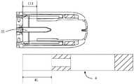
图3是本申请提供的气溶胶产生装置的一实施例的剖视图;3 is a cross-sectional view of an embodiment of the aerosol generating device provided by the present application;
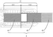
图4是本申请提供的第一气道和气溶胶生成基体的连接结构示意图;4 is a schematic diagram of the connection structure of the first airway provided by the present application and the aerosol-generating substrate;
图5是本申请提供的保温段和叶片段第一实施例的连接结构示意图;5 is a schematic diagram of the connection structure of the insulation section and the first embodiment of the blade segment provided by the present application;
图6是本申请提供的保温段和叶片段第二实施例的连接结构示意图;6 is a schematic diagram of the connection structure of the second embodiment of the insulation section and the blade segment provided by the present application;
图7是本申请提供的保温段和叶片段第三实施例的连接结构示意图;7 is a schematic diagram of the connection structure of the third embodiment of the insulation section and the blade segment provided by the present application;
图8是本申请提供的发热组件的爆炸结构示意图;8 is a schematic diagram of an exploded structure of a heating assembly provided by the present application;
图9是本申请提供的发热组件的一立体结构示意图;FIG. 9 is a schematic three-dimensional structure diagram of the heating element provided by the present application;
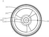
图10是图9提供的发热组件的俯视图;Figure 10 is a top view of the heat generating assembly provided in Figure 9;
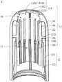
图11是本申请提供的接收器的剖视图;11 is a cross-sectional view of a receiver provided by the present application;
图12是本申请提供的提取器的一立体结构示意图;12 is a schematic three-dimensional structure diagram of the extractor provided by the present application;
图13是图12提供的提取器的俯视图。FIG. 13 is a top view of the extractor provided in FIG. 12 .
具体实施方式Detailed ways
下面将结合本申请实施例中的附图,对本申请实施例中的技术方案进行清楚、完整地描述,显然,所描述的实施例仅是本申请的一部分实施例,而不是全部的实施例。基于本申请中的实施例,本领域普通技术人员在没有做出创造性劳动前提下所获得的所有其他实施例,都属于本申请保护的范围。The technical solutions in the embodiments of the present application will be clearly and completely described below with reference to the drawings in the embodiments of the present application. Obviously, the described embodiments are only a part of the embodiments of the present application, but not all of the embodiments. Based on the embodiments in the present application, all other embodiments obtained by those of ordinary skill in the art without creative efforts shall fall within the protection scope of the present application.
本申请中的术语“第一”、“第二”、仅用于描述目的,而不能理解为指示或暗示相对重要性或者隐含指明所指示的技术特征的数量。由此,限定有“第一”、“第二”、的特征可以明示或者隐含地包括至少一个该特征。本申请实施例中所有方向性指示(诸如上、下、左、右、前、后……)仅用于解释在某一特定姿态(如附图所示)下各部件之间的相对位置关系、运动情况等,如果该特定姿态发生改变时,则该方向性指示也相应地随之改变。此外,术语“包括”和“具有”以及它们任何变形,意图在于覆盖不排他的包含。例如包含了一系列步骤或单元的过程、方法、系统、产品或设备没有限定于已列出的步骤或单元,而是可选地还包括没有列出的步骤或单元,或可选地还包括对于这些过程、方法、产品或设备固有的其它步骤或单元。The terms "first" and "second" in this application are only used for descriptive purposes, and should not be construed as indicating or implying relative importance or implying the number of indicated technical features. Thus, features delimited with "first", "second", may expressly or implicitly include at least one of such features. All directional indications (such as up, down, left, right, front, rear...) in the embodiments of the present application are only used to explain the relative positional relationship between components under a certain posture (as shown in the accompanying drawings). , motion situation, etc., if the specific posture changes, the directional indication also changes accordingly. Furthermore, the terms "comprising" and "having" and any variations thereof are intended to cover non-exclusive inclusion. For example, a process, method, system, product or device comprising a series of steps or units is not limited to the listed steps or units, but optionally also includes unlisted steps or units, or optionally also includes For other steps or units inherent to these processes, methods, products or devices.
在本文中提及“实施例”意味着,结合实施例描述的特定特征、结构或特性可以包含在本申请的至少一个实施例中。在说明书中的各个位置出现该短语并不一定均是指相同的实施例,也不是与其它实施例互斥的独立的或备选的实施例。本领域技术人员显式地和隐式地理解的是,本文所描述的实施例可以与其它实施例相结合。Reference herein to an "embodiment" means that a particular feature, structure, or characteristic described in connection with the embodiment can be included in at least one embodiment of the present application. The appearances of the phrase in various places in the specification are not necessarily all referring to the same embodiment, nor a separate or alternative embodiment that is mutually exclusive of other embodiments. It is explicitly and implicitly understood by those skilled in the art that the embodiments described herein may be combined with other embodiments.
请参阅图1至图3,图1是本申请提供的气溶胶产生装置的一实施例的整体结构示意图,图2是本申请提供的气溶胶产生装置的一实施例的爆炸结构示意图,图3是本申请提供的气溶胶产生装置的一实施例的剖视图。Please refer to FIGS. 1 to 3 , FIG. 1 is a schematic diagram of the overall structure of an embodiment of the aerosol generating device provided by the present application, FIG. 2 is a schematic diagram of an explosion structure of an embodiment of the aerosol generating device provided by the present application, and FIG. 3 It is a cross-sectional view of an embodiment of the aerosol generating device provided in the present application.
本申请提供的气溶胶产生装置100包括接收器1、发热组件2、外壳3、电源组件5和开关6,接收器1设有收容腔10,发热组件2的一端插设于收容腔10内,用以插设于气溶胶生成基体4内并加热气溶胶生成基体4。收容腔10用于收容气溶胶生成基体4,收容腔10的形状和大小不限,可以根据需要设计。电源组件5与发热组件2连接,用于向发热组件2供电。在电源组件5的驱动下,发热组件2加热收容腔10内的气溶胶生成基体4以雾化形成可供用户吸食的气溶胶。气溶胶生成基体4可以是植物草叶类等固态基体。气溶胶产生装置100具体可用于不同的领域,比如医疗、美容、休闲吸食等。电源组件5包括电池51、支架52、驱动件(图未示)以及控制器(图未示)等。电池51用于为发热组件2供电,以使得发热组件2能够加热气溶胶生成基体4以形成气溶胶。开关6用于启动或关闭气溶胶产生装置100。The
请参阅图4至图7,图4是本申请提供的第一气道和气溶胶生成基体的连接结构示意图,图5是本申请提供的保温段和叶片段第一实施例的连接结构示意图,图6是本申请提供的保温段和叶片段第二实施例的连接结构示意图,图7是本申请提供的保温段和叶片段第三实施例的连接结构示意图。Please refer to FIG. 4 to FIG. 7 , FIG. 4 is a schematic diagram of the connection structure of the first air passage and the aerosol-generating substrate provided by the present application, and FIG. 5 is a schematic diagram of the connection structure of the first embodiment of the insulation section and the blade segment provided by the present application. 6 is a schematic diagram of the connection structure of the insulation section and the blade segment provided in the second embodiment of the present application, and FIG. 7 is a schematic diagram of the connection structure of the insulation section and the blade segment provided in the third embodiment of the present application.
在一实施例中,收容腔10的内壁设有第一气道11。第一气道11包括相互连通的保温段111和降温段112,保温段111相对降温段112临近收容腔10底部设置,在收容腔10的轴向方向上,也就是气溶胶生成基体4插入收容腔10的方向上,保温段111的横截面积大于降温段112的横截面积,第一气道11用于供接收器1外部的气体经降温段112和保温段111流入至发热组件2。In one embodiment, the inner wall of the receiving
如图3和图4所示,发热组件2包括底座21和设置于底座21上的发热件22,底座21可以封盖于保温段111的一端,还用于支撑叶片段41,发热件22插设于收容腔10内。发热组件2的一端用于插入叶片段41,具体为发热件22插入叶片段41以实现对叶片段41加热,发热件22可以插入叶片段41的一部分,也可以插入叶片段41的全部长度,提高加热效果,本申请对此不做限定。As shown in FIG. 3 and FIG. 4 , the
具体的,气溶胶生成基体4在使用时插入收容腔10内,气溶胶生成基体4可以包括插设于收容腔10内的叶片段41和提取段42,保温段111可以覆盖至少部分的叶片段41,降温段112用于覆盖至少部分的提取段42。气溶胶生成基体4底部靠近底座21,保温段111设置于靠近底座21的一侧,因此保温段111可以对气溶胶生成基体4靠近底座21的一侧进行保温,即对气溶胶生成基体4的叶片段41进行保温。也就是说,保温段111的内腔与叶片段41是至少部分重合的,保温段111可以完全覆盖叶片段41,也可以只覆盖一部分叶片段41。Specifically, the aerosol-generating
如图5所示,当保温段111完全覆盖叶片段41时,即保温段111的长度与叶片段41的长度之比大于等于1.0,保温段111的横截面积大于降温段112的横截面积,此时保温段111内的空气对流换热系数相对较小,可以提高对叶片段41的保温效果,防止来自发热件22的热量散发过快,提高对气溶胶生成基体4的加热效率和雾化效果,提升用户的抽吸体验。同时,可以降低气溶胶产生装置100的热量损耗。As shown in FIG. 5 , when the
如图6和图7所示,当保温段111只覆盖一部分叶片段41时,例如,保温段111覆盖叶片段41的长度部分与叶片段41的长度之比大于等于0.25,具体可以覆盖如图7所示的三分之一或者覆盖如图6所示的二分之一等,本申请对此不做限定。但是为了保证保温段111对叶片段41的保温效果,保温段111覆盖叶片段41的长度部分与叶片段41的长度之比至少应该大于等于0.25。此时,保温段111对叶片段41的保温效果相对于保温段111完全覆盖叶片段41有所降低,但是降温段112对气溶胶生成基体4的提取段42的降温效果会更明显,对于用户来说,气溶胶的入嘴温度更低。As shown in FIGS. 6 and 7 , when the
在一实施例中,保温段111的长度与叶片段41的长度之比大于等于0.25。需要注意的是,此处为保温段111的长度与叶片段41的长度之间的比值,而不是保温段111覆盖叶片段41的长度与叶片段41的长度之间的比值。如上,由于保温段111可以不完全覆盖叶片段41,因此保温段111的长度与保温段111覆盖叶片段41的长度并不能简单等同,只有当保温段111的长度与叶片段41的长度相等时,保温段111的长度与保温段111覆盖叶片段41的长度才是相等的。In one embodiment, the ratio of the length of the
具体的,如图4至图7所示,由于保温段111需要至少部分覆盖叶片段41,那么保温段111就需要满足一定的长度,以保证对叶片段41的保温效果。叶片段41设置于保温段111内,保温段111需要对叶片段41进行保温时,保温段111的长度至少应该是叶片段41的长度的四分之一,也可以为三分之一、二分之一或者大于等于叶片段41的长度等,本申请对此不做限定。可以理解,保温段111的长度越长,对叶片段41的保温效果越好。在本实施例中,当底座21封盖于保温段111的一端时,气溶胶生成基体4插入收容腔10,气溶胶生成基体4与保温段111靠近的一端与底座21抵接,使得底座21能够对叶片段41形成支撑,即叶片段41远离提取段42的一端与底座21的端面相抵接。优选地,保温段111的长度最长可以为略长于叶片段41的长度,例如,保温段111的长度与叶片段41的长度之比为1.25。如果保温段111的长度过长时,会使得保温段111对气溶胶生成基体4的提取段42进行保温,从而降低降温段112对提取段42的降温效果。Specifically, as shown in FIGS. 4 to 7 , since the
降温段112用于覆盖至少部分气溶胶生成基体4的提取段42,如上所述,降温段112设置于收容腔10远离发热组件2的一侧,且发热件22并不插入至提取段42,不会导致提取段42的温度过高的问题。降温段112的横截面积小于保温段111的横截面积,此时空气在此处的流动速度较快,具有较高的对流换热系数,从而对提取段42起到冷却作用,进而降低气溶胶的入嘴温度。The
如图4所示,在其他实施例中,气溶胶生成基体4还可以包括吸嘴段43,吸嘴段43为提取段42远离叶片段41的一端,可以理解,吸嘴段43是供用户吸食的部分,因此,吸嘴段43可以设置于壳体3的外部,这样更便于用户吸食。同时,由于流至吸嘴段43的气溶胶经过了提取段42的降温,使得进入用户口中的气溶胶温度大大降低,提高了气溶胶的入嘴口感,并进一步提升用户体验。As shown in FIG. 4 , in other embodiments, the aerosol-generating
在一实施例中,降温段112为圆柱腔,降温段112的径向尺寸大于气溶胶生成基体4的径向尺寸,使得气溶胶生成基体4能够穿过降温段112到达保温段111。在其他实施例中,降温段112也可以为棱柱腔、矩形腔等,本申请对此不做限制。In one embodiment, the
请参阅图8至图10,图8是本申请提供的发热组件的爆炸结构示意图,图9是本申请提供的发热组件的一立体结构示意图,图10是图9提供的发热组件的俯视图。Please refer to FIGS. 8 to 10 , FIG. 8 is a schematic diagram of an exploded structure of the heating element provided by the present application, FIG. 9 is a schematic three-dimensional structure of the heating element provided by the present application, and FIG. 10 is a top view of the heating element provided by FIG. 9 .
在一实施例中,底座21朝向收容腔10的端面还设有第二气道23,第二气道23与第一气道11连通,且第二气道23朝向发热件22。第二气道23包括至少一条进气槽231以及汇聚槽232,进气槽231从底座21的边缘向发热件22延伸。汇聚槽232环绕发热件22设置,进气槽231连通汇聚槽232,且汇聚槽232能够被气溶胶生成基体4覆盖。In one embodiment, the end face of the base 21 facing the receiving
具体的,第二气道23与第一气道11连通,使得外部气体能够从第一气道11进入底座21,再从第二气道23进入气溶胶生成基体4内,以将加热形成的气溶胶运送至吸嘴段以供用户抽吸。Specifically, the
如图3和图10所示,汇聚槽232优选为设置在底座21的中心位置,环绕发热件22设置,进气槽231从底座21的边缘向发热件22汇集,且与汇聚槽232连通。使得气体能够在汇聚槽232和发热件22的周围流动。同时,由于气溶胶生成基体4插入收容腔10之后,发热件22从气溶胶生成基体4的底端插入至叶片段41,气溶胶生成基体4的横截面大于汇聚槽232的尺寸,使得气溶胶生成基体4能够覆盖汇聚槽232,从而使得气体也能够进入气溶胶生成基体4内。As shown in FIG. 3 and FIG. 10 , the converging
优选地,进气槽231的数量为多条,多条进气槽231呈放射状设置于汇聚槽232的周侧。具体的,多条进气槽231以等距离放射状的排列方式均布于汇聚槽232的周围,使得第二气道23能够均匀进气。进气槽231侧壁可以是等宽、不规则或者等距离逐渐向汇聚槽232的方向收窄,如,进气槽231侧壁截面为平行的,或者为波浪形的,或者为发射状等,进气槽231侧壁的形状具体不做限定。在本实施例中,进气槽231从底座21的边缘至汇聚槽232逐渐收窄,形成一个喇叭形状的进气槽231,使得气流从四周向中心能够更好地汇聚。Preferably, the number of the
如图8和图9,发热件22包括发热柱221、尖头部222和引线部223,不同于相关技术中发热件22的扁平的结构,本申请的发热件22的主体为柱状,在柱状远离底座21的一端为发热件22的尖头部222。通过将发热件22设计为发热柱221和尖头部222,使得发热件22能够更容易进入气溶胶生成基体4,或者从气溶胶生成基体4取出,不容易发生叶片粘连的情况。同时,柱状的发热件22使得气溶胶生成基体4能够以旋转的方式脱离发热件22,更便于气溶胶生成基体4的提取。引线部223设置于发热柱221远离尖头部222的一端,可以与电源组件5连接,使得电源组件5为发热件22供电以加热气溶胶生成基体4。As shown in FIGS. 8 and 9 , the
如图8和图9所示,在底座21远离发热件22的一侧设置有发热保护壳214,该发热保护壳214为具有空腔的柱状体,发热件22远离提取器132的一端伸入发热保护壳214的柱状体内,使得发热保护壳214部分包围发热件22,并能够对发热件22进行保护。发热保护壳214与底座21可以通过卡接、螺钉连接或者螺纹连接等方式进行连接,具体连接方式本申请不做限定。As shown in FIG. 8 and FIG. 9 , a
在一实施例中,底座21的外侧壁具有第一台阶211和第二台阶212,第一台阶211形成于底座21的外侧壁上靠近进气槽231的一侧,且第一台阶211与多个进气槽231连通,用于汇集来自接收器1的气流。第二台阶212形成于底座21的外侧壁远离进气槽231的一侧。第一台阶211与第二台阶212之间还设有密封件213。In one embodiment, the outer side wall of the
具体的,第一台阶211和第二台阶212均为环形,第一台阶211的上端面与多个进气槽231连通,使得从接收器1进入的气流在第一台阶211的上端面处进行汇集,然后再进入进气槽231和气溶胶生成基体4,从而使得从外部进入第一气道11的气流能够均匀地流入第二气道23。第一台阶211与第二台阶212之间设置密封件213,使得气流不会进入电源组件5中对电源组件5造成损坏。Specifically, the
请参阅图11至图13,图11是本申请提供的接收器的剖视图,图12是本申请提供的提取器的一立体结构示意图,图13是图12提供的提取器的俯视图。Please refer to FIGS. 11 to 13 , FIG. 11 is a cross-sectional view of the receiver provided by the present application, FIG. 12 is a three-dimensional schematic view of the extractor provided by the present application, and FIG. 13 is a top view of the extractor provided by FIG. 12 .
在一实施例中,接收器1包括可拆卸连接的容纳组件12和端盖组件13,容纳组件12和端盖组件13内共同形成收容腔10。端盖组件13设有降温段112,且端盖组件13可拆卸连接于容纳组件12的一端,并与容纳组件12相配合界定出保温段111。In one embodiment, the
具体的,端盖组件13包括端盖131、提取器132和磁性件134,端盖131盖设于提取器132上,且端盖131对应于提取器132的端口设有接受口133,接受口133用于周向定位气溶胶生成基体4,接受口133与提取器132远离底座21的端口对应设置。气溶胶生成基体4从接受口133插入,并容置于收容腔10内。接受口133与气溶胶生成基体4之间形成有进气缝隙1330,用于外部气体进入第一气道11,或者端盖131还设有连通降温段112的进气孔1331,该进气缝隙1330与进气孔1331可以设置其中一个或者两个都设置。进气孔1331可以为开设在端盖131上面或者侧面的一个通孔,也可以是端盖131与气溶胶生成基体4之间预留的进气口,以使得气体可以从该通孔或者进气口中进入第一气道11。磁性件134设置于端盖131和提取器132之间,磁性件134用以与容纳组件12磁吸连接。Specifically, the
具体的,接受口133上设有凸起1332和与凸起1332连接的弧形面1333,凸起1332与气溶胶生成基体4相抵接,可以固定气溶胶生成基体4;弧形面1333与气溶胶生成基体4之间具有一定的间隙,使得外部气体可以进入收容腔10。弧形面1333与气溶胶生成基体4之间的间隙可以作为进气缝隙1330以供外部气体进入。Specifically, the receiving
提取器132可拆卸连接于端盖131内,提取器132设有降温段112,且提取器132和端盖131的内壁之间形成有插接腔136,容纳组件12背离底座21的一端插入插接腔136。The
具体的,提取器132与气溶胶生成基体4之间具有一定的空隙,可以形成该降温段112。提取器132外表面具有一个周向设置的凸环1321,当提取器132设置于端盖131内时,该凸环1321与端盖131之间形成一个空腔,即为插接腔136。容纳组件12远离底座21的一端插入该插接腔136中,以对容纳组件12进行固定。Specifically, there is a certain gap between the
在一实施例中,容纳组件12可以包括磁性容纳管122和定位管121,磁性容纳管122的一端插设于插接腔136内,与提取器132的凸环1321抵接。定位管121套设于磁性容纳管122内,定位管121内具有收容腔10,定位管121的内壁与提取器132的外壁定位配合,提取器132插入收容腔10内并界定出保温段111。In one embodiment, the
具体的,定位管121的内壁与提取器132靠近底座21的外侧壁相抵接,且在提取器132靠近底座21的端部、定位管121的内壁以及底座21的端面之间定位出一个空腔,该空腔为第一气道11的保温段111。当气溶胶生成基体4插入接收器1内的收容腔10时,其底部与底座21的端面接触,气溶胶生成基体4的叶片段41可以至少部分位于保温段111中,使得保温段111能够对叶片段41进行保温。Specifically, the inner wall of the
在其他实施例中,容纳组件12也可以为一体式的单管结构,即磁性容纳管122和定位管121为一个整体嵌设于插接腔136内,与提取器132的凸环1321抵接,同样也可以实现容纳组件12的功能,本申请对此不做限制。In other embodiments, the
磁性件134具体设置于端盖131和提取器132的凸环1321之间,在本实施例中,提取器132、磁性容纳管122和端盖131可以为金属件,磁性容纳管122和磁性件134分别设置于凸环1321的两侧,且端盖131套设于磁性容纳管122和磁性件134的外部,通过磁性件134的磁吸作用,使得磁性容纳管122、提取器132和端盖131可以形成一个一体组合结构,以便于气溶胶产生装置100整体结构的安装。同时,构成该一体组合结构的磁性容纳管122、提取器132和端盖131彼此之间相互磁吸,具有一定的重量,使得气溶胶生成基体4更容易从提取器132中取出。可以理解,提取器132、磁性容纳管122和端盖131也可以为其他材质,即使不形成一体组合结构,也可以实现本申请的功能。磁性件134可以为磁铁或者设有磁性涂层的其他材料构成的结构,具体根据需要进行选择,本申请对此不做限制。The
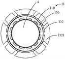
如图12和图13,提取器132的内壁设有至少一条凸筋130,凸筋130用以定位气溶胶生成基体4,并用于引导接收器1外部的气体至发热组件2。12 and 13 , the inner wall of the
具体的,凸筋130设置于提取器132的内壁表面,使得气溶胶生成基体4和提取器132之间形成进气间隙110,以便于外部气体可以从该进气间隙110中流过,到达发热组件2。同时凸筋130可以对气溶胶生成基体4进行固定,使得气溶胶生成基体4和提取器132保持在同轴的位置,不容易发生偏移。凸筋130的数量可以一条或者多条,设置多条凸筋130时,凸筋130相互之间需要间隔设置,且多条凸筋130沿收容腔10的周向分布,以使得收容腔10中有足够的空间供气溶胶生成基体4插入。相邻的两条凸筋130之间的进气间隙110也作为第一气道11的一部分,用于将外部气体导入至发热组件2。在本实施例中,凸筋130分布于提取器132内靠近底座21的一部分内壁,在其他实施例中,凸筋130也可以设置于与接受口133的凸起1332相接触的位置,本申请并不对此进行限制。凸筋130与提取器132可以为一体结构或者在提取器132内单独设置的结构,具体不做限定。凸筋130的具体数量和形状不限,只要能够满足凸筋130彼此之间具有进气间隙110,且能够使得气溶胶生成基体4穿过即可,本申请对此不做限制。Specifically, the
进一步的,凸筋130设有导向面1301,该导向面1301朝向提取器132远离底座21的端口设置,可以用于引导气溶胶生成基体4方便地插入多条凸筋130所限定的定位空间内。导向面1301可以为斜面或者弧面,也可以为其他面,只要能够实现对气溶胶生成基体4的导向作用即可,本申请对此不做限制。Further, the
如图2和图3所示,外壳3设置于电源组件5外部,外壳3上还开设有开孔31,开孔31可以用于安装气溶胶产生装置100的开关6。支架52设置于外壳3内,用于安装并支撑电池51和线路板54等部件。电池51与发热件22连接,用于给发热件22供电,使得发热件22能够对气溶胶生成基体4加热以形成气溶胶供用户抽吸。As shown in FIG. 2 and FIG. 3 , the
如图3和图8所示,端盖组件13与外壳3之间可以通过螺纹、卡接等方式进行连接,密封件213的设置可以防止气流进入电源组件5内,对电源组件5内的部件造成损坏或者腐蚀等。端盖组件13与外壳3之间也可以设置其他密封件或者连接件,以保证端盖组件13与外壳3的紧密连接。As shown in FIG. 3 and FIG. 8 , the
本申请公开的气溶胶产生装置包括:接收器和发热组件,接收器设有收容腔,收容腔用于收容气溶胶生成基体,收容腔的内壁设有第一气道;发热组件的一端插设于收容腔内,用以插设于气溶胶生成基体内并加热气溶胶生成基体;其中,第一气道包括相互连通的保温段和降温段,保温段相对降温段临近收容腔底部设置,在收容腔的轴向方向上,保温段的横截面积大于降温段的横截面积,第一气道用于供接收器外部的气体经降温段和保温段导入至发热组件。通过设置气道的保温段和降温段,既提高了气溶胶雾化效率,又解决了气溶胶入口温度高、影响用户体验的问题。The aerosol generating device disclosed in the present application includes: a receiver and a heating component, the receiver is provided with a receiving cavity, the receiving cavity is used for accommodating the aerosol generating substrate, and the inner wall of the receiving cavity is provided with a first air channel; one end of the heating component is inserted into in the accommodating cavity, to be inserted into the aerosol generating matrix and heating the aerosol generating matrix; wherein, the first air passage includes a heat preservation section and a cooling section that are connected to each other, and the heat preservation section is arranged near the bottom of the accommodating cavity relative to the cooling section. In the axial direction of the accommodating cavity, the cross-sectional area of the heat preservation section is larger than that of the cooling section, and the first air passage is used for introducing the gas outside the receiver to the heating element through the cooling section and the heat preservation section. By setting the heat preservation section and the cooling section of the airway, the aerosol atomization efficiency is improved, and the problem of high aerosol inlet temperature and affecting user experience is solved.
以上所述仅为本申请的实施方式,并非因此限制本申请的专利范围,凡是利用本申请说明书及附图内容所作的等效结构或等效流程变换,或直接或间接运用在其他相关的技术领域,均同理包括在本申请的专利保护范围内。The above description is only an embodiment of the present application, and is not intended to limit the scope of the patent of the present application. Any equivalent structure or equivalent process transformation made by using the contents of the description and drawings of the present application, or directly or indirectly applied to other related technologies Fields are similarly included within the scope of patent protection of this application.
Claims (20)
Translated fromChinesePriority Applications (2)
| Application Number | Priority Date | Filing Date | Title |
|---|---|---|---|
| CN202210536656.XACN114903218A (en) | 2022-05-16 | 2022-05-16 | aerosol generating device |
| PCT/CN2023/080557WO2023221612A1 (en) | 2022-05-16 | 2023-03-09 | Aerosol generating device |
Applications Claiming Priority (1)
| Application Number | Priority Date | Filing Date | Title |
|---|---|---|---|
| CN202210536656.XACN114903218A (en) | 2022-05-16 | 2022-05-16 | aerosol generating device |
Publications (1)
| Publication Number | Publication Date |
|---|---|
| CN114903218Atrue CN114903218A (en) | 2022-08-16 |
Family
ID=82768847
Family Applications (1)
| Application Number | Title | Priority Date | Filing Date |
|---|---|---|---|
| CN202210536656.XAPendingCN114903218A (en) | 2022-05-16 | 2022-05-16 | aerosol generating device |
Country Status (2)
| Country | Link |
|---|---|
| CN (1) | CN114903218A (en) |
| WO (1) | WO2023221612A1 (en) |
Cited By (2)
| Publication number | Priority date | Publication date | Assignee | Title |
|---|---|---|---|---|
| WO2023221611A1 (en)* | 2022-05-16 | 2023-11-23 | 深圳麦时科技有限公司 | Aerosol generating device |
| WO2023221612A1 (en)* | 2022-05-16 | 2023-11-23 | 深圳麦时科技有限公司 | Aerosol generating device |
Citations (8)
| Publication number | Priority date | Publication date | Assignee | Title |
|---|---|---|---|---|
| JP3065356U (en)* | 1999-06-30 | 2000-02-02 | 明 矢野 | Smoking equipment |
| US20140338686A1 (en)* | 2012-01-03 | 2014-11-20 | Philip Morris Products S.A. | Aerosol generating device and system with improved airflow |
| CN110037349A (en)* | 2019-04-02 | 2019-07-23 | 湖南聚能陶瓷材料有限公司 | A kind of micropore ceramics heater and preparation method thereof for electronic cigarette |
| CN113841941A (en)* | 2021-10-25 | 2021-12-28 | 深圳市吉迩科技有限公司 | Aerosol generation system and its products |
| CN113925230A (en)* | 2021-10-12 | 2022-01-14 | 深圳市吉迩科技有限公司 | A kind of aerosol generation product and aerosol generation system |
| CN114052296A (en)* | 2021-11-23 | 2022-02-18 | 深圳麦时科技有限公司 | Aerosol matrix structure and aerosol generating device |
| CN114081207A (en)* | 2021-10-20 | 2022-02-25 | 梅尔斯特(广东)生物科技有限公司 | A suction resistance regulator and an electronic cigarette cartridge comprising the suction resistance regulator |
| CN218790562U (en)* | 2022-05-16 | 2023-04-07 | 深圳麦时科技有限公司 | Aerosol generating device |
Family Cites Families (5)
| Publication number | Priority date | Publication date | Assignee | Title |
|---|---|---|---|---|
| US20220225668A1 (en)* | 2019-04-29 | 2022-07-21 | Philip Morris Products S.A. | Aerosol-generating device with heating zone insulation |
| CN212212687U (en)* | 2020-01-20 | 2020-12-25 | 青岛颐中科技有限公司 | Heating non-burning smoking set |
| CN216135188U (en)* | 2021-07-30 | 2022-03-29 | 深圳麦克韦尔科技有限公司 | Heater and heating atomizing device |
| CN215455431U (en)* | 2021-08-12 | 2022-01-11 | 湖南中烟工业有限责任公司 | A heating assembly for cigarette smoking set and cigarette smoking set |
| CN114903218A (en)* | 2022-05-16 | 2022-08-16 | 深圳麦时科技有限公司 | aerosol generating device |
- 2022
- 2022-05-16CNCN202210536656.XApatent/CN114903218A/enactivePending
- 2023
- 2023-03-09WOPCT/CN2023/080557patent/WO2023221612A1/ennot_activeCeased
Patent Citations (8)
| Publication number | Priority date | Publication date | Assignee | Title |
|---|---|---|---|---|
| JP3065356U (en)* | 1999-06-30 | 2000-02-02 | 明 矢野 | Smoking equipment |
| US20140338686A1 (en)* | 2012-01-03 | 2014-11-20 | Philip Morris Products S.A. | Aerosol generating device and system with improved airflow |
| CN110037349A (en)* | 2019-04-02 | 2019-07-23 | 湖南聚能陶瓷材料有限公司 | A kind of micropore ceramics heater and preparation method thereof for electronic cigarette |
| CN113925230A (en)* | 2021-10-12 | 2022-01-14 | 深圳市吉迩科技有限公司 | A kind of aerosol generation product and aerosol generation system |
| CN114081207A (en)* | 2021-10-20 | 2022-02-25 | 梅尔斯特(广东)生物科技有限公司 | A suction resistance regulator and an electronic cigarette cartridge comprising the suction resistance regulator |
| CN113841941A (en)* | 2021-10-25 | 2021-12-28 | 深圳市吉迩科技有限公司 | Aerosol generation system and its products |
| CN114052296A (en)* | 2021-11-23 | 2022-02-18 | 深圳麦时科技有限公司 | Aerosol matrix structure and aerosol generating device |
| CN218790562U (en)* | 2022-05-16 | 2023-04-07 | 深圳麦时科技有限公司 | Aerosol generating device |
Cited By (2)
| Publication number | Priority date | Publication date | Assignee | Title |
|---|---|---|---|---|
| WO2023221611A1 (en)* | 2022-05-16 | 2023-11-23 | 深圳麦时科技有限公司 | Aerosol generating device |
| WO2023221612A1 (en)* | 2022-05-16 | 2023-11-23 | 深圳麦时科技有限公司 | Aerosol generating device |
Also Published As
| Publication number | Publication date |
|---|---|
| WO2023221612A1 (en) | 2023-11-23 |
Similar Documents
| Publication | Publication Date | Title |
|---|---|---|
| CN108185536B (en) | Electronic cigarette and atomizer thereof | |
| CN217771497U (en) | Aerosol generating device | |
| CN114903218A (en) | aerosol generating device | |
| WO2018041065A1 (en) | Heat-cured electronic cigarette and bowl structure thereof | |
| CN216875000U (en) | Electronic atomization device | |
| CN213639660U (en) | Electronic cigarette and atomizer thereof | |
| WO2023221613A1 (en) | Aerosol generating device | |
| CN112089106A (en) | Nebulizing units and nebulizing assemblies for detoured airways | |
| WO2019157651A1 (en) | Electronic cigarette and heating assembly and heating member thereof | |
| WO2022161052A1 (en) | Aerosol generating device | |
| CN216147240U (en) | Aerosol generating device | |
| WO2022111318A1 (en) | Heater, and heating atomization apparatus | |
| CN108323823A (en) | A kind of aerosol generating system and aerosol generating device for improving air-flow | |
| CN217791479U (en) | Aerosol generating device | |
| TW202122000A (en) | Aerosol generating device with non-linear airflow channels | |
| CN220343664U (en) | Aerosol generating rod heating assembly and aerosol generating device | |
| WO2024174663A1 (en) | Heating assembly and aerosol generating device | |
| WO2024046133A1 (en) | Electromagnetic coil, atomization structure, atomizer, and electronic atomization device | |
| CN218790562U (en) | Aerosol generating device | |
| CN112617285B (en) | Atomizer and electronic atomization device | |
| CN113854640A (en) | Heating smoking set for cigarette | |
| CN110859330B (en) | Preventing cigarette cartridges and e-cigarettes from overheating the mouthpiece | |
| CN111449302B (en) | Heat-insulating non-contact type electronic cigarette heating device and use method thereof | |
| CN217161101U (en) | Atomization assembly and electronic atomizer | |
| CN211482979U (en) | Cigarette cartridge and electronic cigarette capable of preventing temperature of cigarette holder from being too high |
Legal Events
| Date | Code | Title | Description |
|---|---|---|---|
| PB01 | Publication | ||
| PB01 | Publication | ||
| SE01 | Entry into force of request for substantive examination | ||
| SE01 | Entry into force of request for substantive examination |