CN114902383A - Substrate processing apparatus, method for manufacturing semiconductor device, and program - Google Patents
Substrate processing apparatus, method for manufacturing semiconductor device, and programDownload PDFInfo
- Publication number
- CN114902383A CN114902383ACN202080091468.XACN202080091468ACN114902383ACN 114902383 ACN114902383 ACN 114902383ACN 202080091468 ACN202080091468 ACN 202080091468ACN 114902383 ACN114902383 ACN 114902383A
- Authority
- CN
- China
- Prior art keywords
- gas
- substrate
- processing
- inert gas
- nozzle
- Prior art date
- Legal status (The legal status is an assumption and is not a legal conclusion. Google has not performed a legal analysis and makes no representation as to the accuracy of the status listed.)
- Pending
Links
Images


Classifications
- C—CHEMISTRY; METALLURGY
- C23—COATING METALLIC MATERIAL; COATING MATERIAL WITH METALLIC MATERIAL; CHEMICAL SURFACE TREATMENT; DIFFUSION TREATMENT OF METALLIC MATERIAL; COATING BY VACUUM EVAPORATION, BY SPUTTERING, BY ION IMPLANTATION OR BY CHEMICAL VAPOUR DEPOSITION, IN GENERAL; INHIBITING CORROSION OF METALLIC MATERIAL OR INCRUSTATION IN GENERAL
- C23C—COATING METALLIC MATERIAL; COATING MATERIAL WITH METALLIC MATERIAL; SURFACE TREATMENT OF METALLIC MATERIAL BY DIFFUSION INTO THE SURFACE, BY CHEMICAL CONVERSION OR SUBSTITUTION; COATING BY VACUUM EVAPORATION, BY SPUTTERING, BY ION IMPLANTATION OR BY CHEMICAL VAPOUR DEPOSITION, IN GENERAL
- C23C16/00—Chemical coating by decomposition of gaseous compounds, without leaving reaction products of surface material in the coating, i.e. chemical vapour deposition [CVD] processes
- C23C16/44—Chemical coating by decomposition of gaseous compounds, without leaving reaction products of surface material in the coating, i.e. chemical vapour deposition [CVD] processes characterised by the method of coating
- C23C16/455—Chemical coating by decomposition of gaseous compounds, without leaving reaction products of surface material in the coating, i.e. chemical vapour deposition [CVD] processes characterised by the method of coating characterised by the method used for introducing gases into reaction chamber or for modifying gas flows in reaction chamber
- C23C16/45519—Inert gas curtains
- C—CHEMISTRY; METALLURGY
- C23—COATING METALLIC MATERIAL; COATING MATERIAL WITH METALLIC MATERIAL; CHEMICAL SURFACE TREATMENT; DIFFUSION TREATMENT OF METALLIC MATERIAL; COATING BY VACUUM EVAPORATION, BY SPUTTERING, BY ION IMPLANTATION OR BY CHEMICAL VAPOUR DEPOSITION, IN GENERAL; INHIBITING CORROSION OF METALLIC MATERIAL OR INCRUSTATION IN GENERAL
- C23C—COATING METALLIC MATERIAL; COATING MATERIAL WITH METALLIC MATERIAL; SURFACE TREATMENT OF METALLIC MATERIAL BY DIFFUSION INTO THE SURFACE, BY CHEMICAL CONVERSION OR SUBSTITUTION; COATING BY VACUUM EVAPORATION, BY SPUTTERING, BY ION IMPLANTATION OR BY CHEMICAL VAPOUR DEPOSITION, IN GENERAL
- C23C16/00—Chemical coating by decomposition of gaseous compounds, without leaving reaction products of surface material in the coating, i.e. chemical vapour deposition [CVD] processes
- C23C16/22—Chemical coating by decomposition of gaseous compounds, without leaving reaction products of surface material in the coating, i.e. chemical vapour deposition [CVD] processes characterised by the deposition of inorganic material, other than metallic material
- C23C16/30—Deposition of compounds, mixtures or solid solutions, e.g. borides, carbides, nitrides
- C23C16/34—Nitrides
- C23C16/345—Silicon nitride
- C—CHEMISTRY; METALLURGY
- C23—COATING METALLIC MATERIAL; COATING MATERIAL WITH METALLIC MATERIAL; CHEMICAL SURFACE TREATMENT; DIFFUSION TREATMENT OF METALLIC MATERIAL; COATING BY VACUUM EVAPORATION, BY SPUTTERING, BY ION IMPLANTATION OR BY CHEMICAL VAPOUR DEPOSITION, IN GENERAL; INHIBITING CORROSION OF METALLIC MATERIAL OR INCRUSTATION IN GENERAL
- C23C—COATING METALLIC MATERIAL; COATING MATERIAL WITH METALLIC MATERIAL; SURFACE TREATMENT OF METALLIC MATERIAL BY DIFFUSION INTO THE SURFACE, BY CHEMICAL CONVERSION OR SUBSTITUTION; COATING BY VACUUM EVAPORATION, BY SPUTTERING, BY ION IMPLANTATION OR BY CHEMICAL VAPOUR DEPOSITION, IN GENERAL
- C23C16/00—Chemical coating by decomposition of gaseous compounds, without leaving reaction products of surface material in the coating, i.e. chemical vapour deposition [CVD] processes
- C23C16/44—Chemical coating by decomposition of gaseous compounds, without leaving reaction products of surface material in the coating, i.e. chemical vapour deposition [CVD] processes characterised by the method of coating
- C23C16/4401—Means for minimising impurities, e.g. dust, moisture or residual gas, in the reaction chamber
- C23C16/4408—Means for minimising impurities, e.g. dust, moisture or residual gas, in the reaction chamber by purging residual gases from the reaction chamber or gas lines
- C—CHEMISTRY; METALLURGY
- C23—COATING METALLIC MATERIAL; COATING MATERIAL WITH METALLIC MATERIAL; CHEMICAL SURFACE TREATMENT; DIFFUSION TREATMENT OF METALLIC MATERIAL; COATING BY VACUUM EVAPORATION, BY SPUTTERING, BY ION IMPLANTATION OR BY CHEMICAL VAPOUR DEPOSITION, IN GENERAL; INHIBITING CORROSION OF METALLIC MATERIAL OR INCRUSTATION IN GENERAL
- C23C—COATING METALLIC MATERIAL; COATING MATERIAL WITH METALLIC MATERIAL; SURFACE TREATMENT OF METALLIC MATERIAL BY DIFFUSION INTO THE SURFACE, BY CHEMICAL CONVERSION OR SUBSTITUTION; COATING BY VACUUM EVAPORATION, BY SPUTTERING, BY ION IMPLANTATION OR BY CHEMICAL VAPOUR DEPOSITION, IN GENERAL
- C23C16/00—Chemical coating by decomposition of gaseous compounds, without leaving reaction products of surface material in the coating, i.e. chemical vapour deposition [CVD] processes
- C23C16/44—Chemical coating by decomposition of gaseous compounds, without leaving reaction products of surface material in the coating, i.e. chemical vapour deposition [CVD] processes characterised by the method of coating
- C23C16/4412—Details relating to the exhausts, e.g. pumps, filters, scrubbers, particle traps
- C—CHEMISTRY; METALLURGY
- C23—COATING METALLIC MATERIAL; COATING MATERIAL WITH METALLIC MATERIAL; CHEMICAL SURFACE TREATMENT; DIFFUSION TREATMENT OF METALLIC MATERIAL; COATING BY VACUUM EVAPORATION, BY SPUTTERING, BY ION IMPLANTATION OR BY CHEMICAL VAPOUR DEPOSITION, IN GENERAL; INHIBITING CORROSION OF METALLIC MATERIAL OR INCRUSTATION IN GENERAL
- C23C—COATING METALLIC MATERIAL; COATING MATERIAL WITH METALLIC MATERIAL; SURFACE TREATMENT OF METALLIC MATERIAL BY DIFFUSION INTO THE SURFACE, BY CHEMICAL CONVERSION OR SUBSTITUTION; COATING BY VACUUM EVAPORATION, BY SPUTTERING, BY ION IMPLANTATION OR BY CHEMICAL VAPOUR DEPOSITION, IN GENERAL
- C23C16/00—Chemical coating by decomposition of gaseous compounds, without leaving reaction products of surface material in the coating, i.e. chemical vapour deposition [CVD] processes
- C23C16/44—Chemical coating by decomposition of gaseous compounds, without leaving reaction products of surface material in the coating, i.e. chemical vapour deposition [CVD] processes characterised by the method of coating
- C23C16/455—Chemical coating by decomposition of gaseous compounds, without leaving reaction products of surface material in the coating, i.e. chemical vapour deposition [CVD] processes characterised by the method of coating characterised by the method used for introducing gases into reaction chamber or for modifying gas flows in reaction chamber
- C23C16/45502—Flow conditions in reaction chamber
- C23C16/45506—Turbulent flow
- C—CHEMISTRY; METALLURGY
- C23—COATING METALLIC MATERIAL; COATING MATERIAL WITH METALLIC MATERIAL; CHEMICAL SURFACE TREATMENT; DIFFUSION TREATMENT OF METALLIC MATERIAL; COATING BY VACUUM EVAPORATION, BY SPUTTERING, BY ION IMPLANTATION OR BY CHEMICAL VAPOUR DEPOSITION, IN GENERAL; INHIBITING CORROSION OF METALLIC MATERIAL OR INCRUSTATION IN GENERAL
- C23C—COATING METALLIC MATERIAL; COATING MATERIAL WITH METALLIC MATERIAL; SURFACE TREATMENT OF METALLIC MATERIAL BY DIFFUSION INTO THE SURFACE, BY CHEMICAL CONVERSION OR SUBSTITUTION; COATING BY VACUUM EVAPORATION, BY SPUTTERING, BY ION IMPLANTATION OR BY CHEMICAL VAPOUR DEPOSITION, IN GENERAL
- C23C16/00—Chemical coating by decomposition of gaseous compounds, without leaving reaction products of surface material in the coating, i.e. chemical vapour deposition [CVD] processes
- C23C16/44—Chemical coating by decomposition of gaseous compounds, without leaving reaction products of surface material in the coating, i.e. chemical vapour deposition [CVD] processes characterised by the method of coating
- C23C16/455—Chemical coating by decomposition of gaseous compounds, without leaving reaction products of surface material in the coating, i.e. chemical vapour deposition [CVD] processes characterised by the method of coating characterised by the method used for introducing gases into reaction chamber or for modifying gas flows in reaction chamber
- C23C16/45517—Confinement of gases to vicinity of substrate
- C—CHEMISTRY; METALLURGY
- C23—COATING METALLIC MATERIAL; COATING MATERIAL WITH METALLIC MATERIAL; CHEMICAL SURFACE TREATMENT; DIFFUSION TREATMENT OF METALLIC MATERIAL; COATING BY VACUUM EVAPORATION, BY SPUTTERING, BY ION IMPLANTATION OR BY CHEMICAL VAPOUR DEPOSITION, IN GENERAL; INHIBITING CORROSION OF METALLIC MATERIAL OR INCRUSTATION IN GENERAL
- C23C—COATING METALLIC MATERIAL; COATING MATERIAL WITH METALLIC MATERIAL; SURFACE TREATMENT OF METALLIC MATERIAL BY DIFFUSION INTO THE SURFACE, BY CHEMICAL CONVERSION OR SUBSTITUTION; COATING BY VACUUM EVAPORATION, BY SPUTTERING, BY ION IMPLANTATION OR BY CHEMICAL VAPOUR DEPOSITION, IN GENERAL
- C23C16/00—Chemical coating by decomposition of gaseous compounds, without leaving reaction products of surface material in the coating, i.e. chemical vapour deposition [CVD] processes
- C23C16/44—Chemical coating by decomposition of gaseous compounds, without leaving reaction products of surface material in the coating, i.e. chemical vapour deposition [CVD] processes characterised by the method of coating
- C23C16/455—Chemical coating by decomposition of gaseous compounds, without leaving reaction products of surface material in the coating, i.e. chemical vapour deposition [CVD] processes characterised by the method of coating characterised by the method used for introducing gases into reaction chamber or for modifying gas flows in reaction chamber
- C23C16/45523—Pulsed gas flow or change of composition over time
- C—CHEMISTRY; METALLURGY
- C23—COATING METALLIC MATERIAL; COATING MATERIAL WITH METALLIC MATERIAL; CHEMICAL SURFACE TREATMENT; DIFFUSION TREATMENT OF METALLIC MATERIAL; COATING BY VACUUM EVAPORATION, BY SPUTTERING, BY ION IMPLANTATION OR BY CHEMICAL VAPOUR DEPOSITION, IN GENERAL; INHIBITING CORROSION OF METALLIC MATERIAL OR INCRUSTATION IN GENERAL
- C23C—COATING METALLIC MATERIAL; COATING MATERIAL WITH METALLIC MATERIAL; SURFACE TREATMENT OF METALLIC MATERIAL BY DIFFUSION INTO THE SURFACE, BY CHEMICAL CONVERSION OR SUBSTITUTION; COATING BY VACUUM EVAPORATION, BY SPUTTERING, BY ION IMPLANTATION OR BY CHEMICAL VAPOUR DEPOSITION, IN GENERAL
- C23C16/00—Chemical coating by decomposition of gaseous compounds, without leaving reaction products of surface material in the coating, i.e. chemical vapour deposition [CVD] processes
- C23C16/44—Chemical coating by decomposition of gaseous compounds, without leaving reaction products of surface material in the coating, i.e. chemical vapour deposition [CVD] processes characterised by the method of coating
- C23C16/455—Chemical coating by decomposition of gaseous compounds, without leaving reaction products of surface material in the coating, i.e. chemical vapour deposition [CVD] processes characterised by the method of coating characterised by the method used for introducing gases into reaction chamber or for modifying gas flows in reaction chamber
- C23C16/45563—Gas nozzles
- C23C16/45574—Nozzles for more than one gas
- C—CHEMISTRY; METALLURGY
- C23—COATING METALLIC MATERIAL; COATING MATERIAL WITH METALLIC MATERIAL; CHEMICAL SURFACE TREATMENT; DIFFUSION TREATMENT OF METALLIC MATERIAL; COATING BY VACUUM EVAPORATION, BY SPUTTERING, BY ION IMPLANTATION OR BY CHEMICAL VAPOUR DEPOSITION, IN GENERAL; INHIBITING CORROSION OF METALLIC MATERIAL OR INCRUSTATION IN GENERAL
- C23C—COATING METALLIC MATERIAL; COATING MATERIAL WITH METALLIC MATERIAL; SURFACE TREATMENT OF METALLIC MATERIAL BY DIFFUSION INTO THE SURFACE, BY CHEMICAL CONVERSION OR SUBSTITUTION; COATING BY VACUUM EVAPORATION, BY SPUTTERING, BY ION IMPLANTATION OR BY CHEMICAL VAPOUR DEPOSITION, IN GENERAL
- C23C16/00—Chemical coating by decomposition of gaseous compounds, without leaving reaction products of surface material in the coating, i.e. chemical vapour deposition [CVD] processes
- C23C16/44—Chemical coating by decomposition of gaseous compounds, without leaving reaction products of surface material in the coating, i.e. chemical vapour deposition [CVD] processes characterised by the method of coating
- C23C16/455—Chemical coating by decomposition of gaseous compounds, without leaving reaction products of surface material in the coating, i.e. chemical vapour deposition [CVD] processes characterised by the method of coating characterised by the method used for introducing gases into reaction chamber or for modifying gas flows in reaction chamber
- C23C16/45563—Gas nozzles
- C23C16/45578—Elongated nozzles, tubes with holes
- C—CHEMISTRY; METALLURGY
- C23—COATING METALLIC MATERIAL; COATING MATERIAL WITH METALLIC MATERIAL; CHEMICAL SURFACE TREATMENT; DIFFUSION TREATMENT OF METALLIC MATERIAL; COATING BY VACUUM EVAPORATION, BY SPUTTERING, BY ION IMPLANTATION OR BY CHEMICAL VAPOUR DEPOSITION, IN GENERAL; INHIBITING CORROSION OF METALLIC MATERIAL OR INCRUSTATION IN GENERAL
- C23C—COATING METALLIC MATERIAL; COATING MATERIAL WITH METALLIC MATERIAL; SURFACE TREATMENT OF METALLIC MATERIAL BY DIFFUSION INTO THE SURFACE, BY CHEMICAL CONVERSION OR SUBSTITUTION; COATING BY VACUUM EVAPORATION, BY SPUTTERING, BY ION IMPLANTATION OR BY CHEMICAL VAPOUR DEPOSITION, IN GENERAL
- C23C16/00—Chemical coating by decomposition of gaseous compounds, without leaving reaction products of surface material in the coating, i.e. chemical vapour deposition [CVD] processes
- C23C16/44—Chemical coating by decomposition of gaseous compounds, without leaving reaction products of surface material in the coating, i.e. chemical vapour deposition [CVD] processes characterised by the method of coating
- C23C16/458—Chemical coating by decomposition of gaseous compounds, without leaving reaction products of surface material in the coating, i.e. chemical vapour deposition [CVD] processes characterised by the method of coating characterised by the method used for supporting substrates in the reaction chamber
- C23C16/4582—Rigid and flat substrates, e.g. plates or discs
- C23C16/4583—Rigid and flat substrates, e.g. plates or discs the substrate being supported substantially horizontally
- C—CHEMISTRY; METALLURGY
- C23—COATING METALLIC MATERIAL; COATING MATERIAL WITH METALLIC MATERIAL; CHEMICAL SURFACE TREATMENT; DIFFUSION TREATMENT OF METALLIC MATERIAL; COATING BY VACUUM EVAPORATION, BY SPUTTERING, BY ION IMPLANTATION OR BY CHEMICAL VAPOUR DEPOSITION, IN GENERAL; INHIBITING CORROSION OF METALLIC MATERIAL OR INCRUSTATION IN GENERAL
- C23C—COATING METALLIC MATERIAL; COATING MATERIAL WITH METALLIC MATERIAL; SURFACE TREATMENT OF METALLIC MATERIAL BY DIFFUSION INTO THE SURFACE, BY CHEMICAL CONVERSION OR SUBSTITUTION; COATING BY VACUUM EVAPORATION, BY SPUTTERING, BY ION IMPLANTATION OR BY CHEMICAL VAPOUR DEPOSITION, IN GENERAL
- C23C16/00—Chemical coating by decomposition of gaseous compounds, without leaving reaction products of surface material in the coating, i.e. chemical vapour deposition [CVD] processes
- C23C16/44—Chemical coating by decomposition of gaseous compounds, without leaving reaction products of surface material in the coating, i.e. chemical vapour deposition [CVD] processes characterised by the method of coating
- C23C16/52—Controlling or regulating the coating process
- H—ELECTRICITY
- H01—ELECTRIC ELEMENTS
- H01L—SEMICONDUCTOR DEVICES NOT COVERED BY CLASS H10
- H01L21/00—Processes or apparatus adapted for the manufacture or treatment of semiconductor or solid state devices or of parts thereof
- H01L21/02—Manufacture or treatment of semiconductor devices or of parts thereof
- H01L21/02104—Forming layers
- H01L21/02107—Forming insulating materials on a substrate
- H01L21/02109—Forming insulating materials on a substrate characterised by the type of layer, e.g. type of material, porous/non-porous, pre-cursors, mixtures or laminates
- H01L21/02112—Forming insulating materials on a substrate characterised by the type of layer, e.g. type of material, porous/non-porous, pre-cursors, mixtures or laminates characterised by the material of the layer
- H01L21/02123—Forming insulating materials on a substrate characterised by the type of layer, e.g. type of material, porous/non-porous, pre-cursors, mixtures or laminates characterised by the material of the layer the material containing silicon
- H01L21/0217—Forming insulating materials on a substrate characterised by the type of layer, e.g. type of material, porous/non-porous, pre-cursors, mixtures or laminates characterised by the material of the layer the material containing silicon the material being a silicon nitride not containing oxygen, e.g. SixNy or SixByNz
- H—ELECTRICITY
- H01—ELECTRIC ELEMENTS
- H01L—SEMICONDUCTOR DEVICES NOT COVERED BY CLASS H10
- H01L21/00—Processes or apparatus adapted for the manufacture or treatment of semiconductor or solid state devices or of parts thereof
- H01L21/02—Manufacture or treatment of semiconductor devices or of parts thereof
- H01L21/02104—Forming layers
- H01L21/02107—Forming insulating materials on a substrate
- H01L21/02109—Forming insulating materials on a substrate characterised by the type of layer, e.g. type of material, porous/non-porous, pre-cursors, mixtures or laminates
- H01L21/02205—Forming insulating materials on a substrate characterised by the type of layer, e.g. type of material, porous/non-porous, pre-cursors, mixtures or laminates the layer being characterised by the precursor material for deposition
- H01L21/02208—Forming insulating materials on a substrate characterised by the type of layer, e.g. type of material, porous/non-porous, pre-cursors, mixtures or laminates the layer being characterised by the precursor material for deposition the precursor containing a compound comprising Si
- H01L21/02211—Forming insulating materials on a substrate characterised by the type of layer, e.g. type of material, porous/non-porous, pre-cursors, mixtures or laminates the layer being characterised by the precursor material for deposition the precursor containing a compound comprising Si the compound being a silane, e.g. disilane, methylsilane or chlorosilane
- H—ELECTRICITY
- H01—ELECTRIC ELEMENTS
- H01L—SEMICONDUCTOR DEVICES NOT COVERED BY CLASS H10
- H01L21/00—Processes or apparatus adapted for the manufacture or treatment of semiconductor or solid state devices or of parts thereof
- H01L21/02—Manufacture or treatment of semiconductor devices or of parts thereof
- H01L21/02104—Forming layers
- H01L21/02107—Forming insulating materials on a substrate
- H01L21/02225—Forming insulating materials on a substrate characterised by the process for the formation of the insulating layer
- H01L21/0226—Forming insulating materials on a substrate characterised by the process for the formation of the insulating layer formation by a deposition process
- H01L21/02263—Forming insulating materials on a substrate characterised by the process for the formation of the insulating layer formation by a deposition process deposition from the gas or vapour phase
- H01L21/02271—Forming insulating materials on a substrate characterised by the process for the formation of the insulating layer formation by a deposition process deposition from the gas or vapour phase deposition by decomposition or reaction of gaseous or vapour phase compounds, i.e. chemical vapour deposition
- H01L21/0228—Forming insulating materials on a substrate characterised by the process for the formation of the insulating layer formation by a deposition process deposition from the gas or vapour phase deposition by decomposition or reaction of gaseous or vapour phase compounds, i.e. chemical vapour deposition deposition by cyclic CVD, e.g. ALD, ALE, pulsed CVD
- H—ELECTRICITY
- H01—ELECTRIC ELEMENTS
- H01L—SEMICONDUCTOR DEVICES NOT COVERED BY CLASS H10
- H01L21/00—Processes or apparatus adapted for the manufacture or treatment of semiconductor or solid state devices or of parts thereof
- H01L21/02—Manufacture or treatment of semiconductor devices or of parts thereof
- H01L21/04—Manufacture or treatment of semiconductor devices or of parts thereof the devices having potential barriers, e.g. a PN junction, depletion layer or carrier concentration layer
- H01L21/18—Manufacture or treatment of semiconductor devices or of parts thereof the devices having potential barriers, e.g. a PN junction, depletion layer or carrier concentration layer the devices having semiconductor bodies comprising elements of Group IV of the Periodic Table or AIIIBV compounds with or without impurities, e.g. doping materials
- H01L21/30—Treatment of semiconductor bodies using processes or apparatus not provided for in groups H01L21/20 - H01L21/26
- H01L21/31—Treatment of semiconductor bodies using processes or apparatus not provided for in groups H01L21/20 - H01L21/26 to form insulating layers thereon, e.g. for masking or by using photolithographic techniques; After treatment of these layers; Selection of materials for these layers
- H—ELECTRICITY
- H01—ELECTRIC ELEMENTS
- H01L—SEMICONDUCTOR DEVICES NOT COVERED BY CLASS H10
- H01L21/00—Processes or apparatus adapted for the manufacture or treatment of semiconductor or solid state devices or of parts thereof
- H01L21/67—Apparatus specially adapted for handling semiconductor or electric solid state devices during manufacture or treatment thereof; Apparatus specially adapted for handling wafers during manufacture or treatment of semiconductor or electric solid state devices or components ; Apparatus not specifically provided for elsewhere
- H01L21/67005—Apparatus not specifically provided for elsewhere
- H01L21/67011—Apparatus for manufacture or treatment
- H01L21/67017—Apparatus for fluid treatment
- H—ELECTRICITY
- H01—ELECTRIC ELEMENTS
- H01L—SEMICONDUCTOR DEVICES NOT COVERED BY CLASS H10
- H01L21/00—Processes or apparatus adapted for the manufacture or treatment of semiconductor or solid state devices or of parts thereof
- H01L21/67—Apparatus specially adapted for handling semiconductor or electric solid state devices during manufacture or treatment thereof; Apparatus specially adapted for handling wafers during manufacture or treatment of semiconductor or electric solid state devices or components ; Apparatus not specifically provided for elsewhere
- H01L21/67005—Apparatus not specifically provided for elsewhere
- H01L21/67011—Apparatus for manufacture or treatment
- H01L21/67098—Apparatus for thermal treatment
- H01L21/67103—Apparatus for thermal treatment mainly by conduction
- C—CHEMISTRY; METALLURGY
- C23—COATING METALLIC MATERIAL; COATING MATERIAL WITH METALLIC MATERIAL; CHEMICAL SURFACE TREATMENT; DIFFUSION TREATMENT OF METALLIC MATERIAL; COATING BY VACUUM EVAPORATION, BY SPUTTERING, BY ION IMPLANTATION OR BY CHEMICAL VAPOUR DEPOSITION, IN GENERAL; INHIBITING CORROSION OF METALLIC MATERIAL OR INCRUSTATION IN GENERAL
- C23C—COATING METALLIC MATERIAL; COATING MATERIAL WITH METALLIC MATERIAL; SURFACE TREATMENT OF METALLIC MATERIAL BY DIFFUSION INTO THE SURFACE, BY CHEMICAL CONVERSION OR SUBSTITUTION; COATING BY VACUUM EVAPORATION, BY SPUTTERING, BY ION IMPLANTATION OR BY CHEMICAL VAPOUR DEPOSITION, IN GENERAL
- C23C16/00—Chemical coating by decomposition of gaseous compounds, without leaving reaction products of surface material in the coating, i.e. chemical vapour deposition [CVD] processes
- C23C16/44—Chemical coating by decomposition of gaseous compounds, without leaving reaction products of surface material in the coating, i.e. chemical vapour deposition [CVD] processes characterised by the method of coating
- C23C16/455—Chemical coating by decomposition of gaseous compounds, without leaving reaction products of surface material in the coating, i.e. chemical vapour deposition [CVD] processes characterised by the method of coating characterised by the method used for introducing gases into reaction chamber or for modifying gas flows in reaction chamber
- C23C16/45523—Pulsed gas flow or change of composition over time
- C23C16/45525—Atomic layer deposition [ALD]
- C23C16/45544—Atomic layer deposition [ALD] characterized by the apparatus
- C23C16/45548—Atomic layer deposition [ALD] characterized by the apparatus having arrangements for gas injection at different locations of the reactor for each ALD half-reaction
Landscapes
- Chemical & Material Sciences (AREA)
- Engineering & Computer Science (AREA)
- Chemical Kinetics & Catalysis (AREA)
- Organic Chemistry (AREA)
- Metallurgy (AREA)
- Mechanical Engineering (AREA)
- Materials Engineering (AREA)
- General Chemical & Material Sciences (AREA)
- Physics & Mathematics (AREA)
- Computer Hardware Design (AREA)
- Power Engineering (AREA)
- Microelectronics & Electronic Packaging (AREA)
- Manufacturing & Machinery (AREA)
- General Physics & Mathematics (AREA)
- Condensed Matter Physics & Semiconductors (AREA)
- Fluid Mechanics (AREA)
- Inorganic Chemistry (AREA)
- Formation Of Insulating Films (AREA)
- Chemical Vapour Deposition (AREA)
- Encapsulation Of And Coatings For Semiconductor Or Solid State Devices (AREA)
- Design And Manufacture Of Integrated Circuits (AREA)
Abstract
Translated fromChinese
Description
Translated fromChinese技术领域technical field
本公开涉及基板处理装置、半导体装置的制造方法以及程序。The present disclosure relates to a substrate processing apparatus, a method of manufacturing a semiconductor device, and a program.
背景技术Background technique
作为半导体装置(器件)的制造工序的一个工序,进行对处理室内的基板(晶圆)供给处理气体,在基板上形成膜的处理。伴随着半导体器件的高精细化、高深层化,在处理室内的晶圆为图案晶圆的情况下,由于在晶圆的中心附近处理气体的供给量不足,因此有时形成在晶圆上的膜的面内膜厚均匀性恶化。对此,有时将处理气体供给至晶圆中心,提高晶圆上的面内膜厚均匀性(例如参照专利文献1、2)。As one of the steps of manufacturing a semiconductor device (device), a process of supplying a process gas to a substrate (wafer) in a process chamber to form a film on the substrate is performed. With the development of high-definition and high-depth semiconductor devices, when the wafer in the processing chamber is a patterned wafer, the supply amount of the processing gas is insufficient near the center of the wafer, so the film may be formed on the wafer. Deterioration of in-face film thickness uniformity. In contrast, in some cases, a process gas is supplied to the center of the wafer to improve the in-plane thickness uniformity on the wafer (for example, refer to
现有技术文献prior art literature
专利文献Patent Literature
专利文献1:国际公开第2018/154823号小册子Patent Document 1: International Publication No. 2018/154823 Pamphlet
专利文献2:国际公开第2016/157401号小册子Patent Document 2: International Publication No. 2016/157401 Pamphlet
发明内容SUMMARY OF THE INVENTION
发明要解决的课题The problem to be solved by the invention
本公开的目的在于,提供一种提高形成在基板上的膜的面内膜厚均匀性的结构。An object of the present disclosure is to provide a structure for improving the in-plane film thickness uniformity of a film formed on a substrate.
用于解决课题的手段means of solving problems
根据本公开的一个方式,提供如下技术,具备:According to one embodiment of the present disclosure, the following technologies are provided, which have:
处理气体喷嘴,其向处理基板的处理室供给处理气体;a processing gas nozzle that supplies a processing gas to a processing chamber for processing the substrate;
惰性气体喷嘴,其被配置为与所述处理气体喷嘴在所述基板的周向上隔开预定距离,并向所述处理室供给惰性气体;以及an inert gas nozzle configured to be spaced apart from the process gas nozzle by a predetermined distance in the circumferential direction of the substrate, and to supply an inert gas to the process chamber; and
反应管,其在内部构成所述处理室,并具有以收容所述处理气体喷嘴的方式向外侧突出的第一突出部和以收容所述惰性气体喷嘴的方式向外侧突出的第二突出部,a reaction tube which constitutes the processing chamber inside, and has a first protruding portion protruding outward to accommodate the processing gas nozzle, and a second protruding portion protruding outward to accommodate the inert gas nozzle,
以使所述处理气体的流动方向朝向所述基板侧的方式,朝向所述处理气体喷嘴供给从所述惰性气体喷嘴供给的所述惰性气体。The inert gas supplied from the inert gas nozzle is supplied toward the processing gas nozzle so that the flow direction of the processing gas is directed toward the substrate side.
发明效果Invention effect
根据本公开,能够提供一种提高形成在基板上的膜的面内膜厚均匀性的结构。According to the present disclosure, it is possible to provide a structure that improves the in-plane film thickness uniformity of a film formed on a substrate.
附图说明Description of drawings
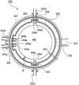
图1是在本公开的一实施方式中优选使用的基板处理装置的概略结构图,是以纵剖视图表示处理炉部分的图。FIG. 1 is a schematic configuration diagram of a substrate processing apparatus preferably used in an embodiment of the present disclosure, and is a longitudinal cross-sectional view showing a processing furnace portion.
图2是以图1的A-A线剖视图表示在本公开的一实施方式中优选使用的基板处理装置的处理炉的一部分的图。2 is a cross-sectional view taken along the line A-A in FIG. 1 , showing a part of a processing furnace of the substrate processing apparatus preferably used in the embodiment of the present disclosure.
图3是在本公开的一实施方式中优选使用的基板处理装置的控制器的概略结构图,是以框图表示控制器的控制系统的图。3 is a schematic configuration diagram of a controller of a substrate processing apparatus preferably used in an embodiment of the present disclosure, and is a block diagram showing a control system of the controller.
图4是表示在本公开的一实施方式中优选使用的基板处理装置的成膜顺序的图。FIG. 4 is a diagram showing a film-forming procedure of a substrate processing apparatus preferably used in an embodiment of the present disclosure.
图5中的(A)是表示在本公开的一实施方式中优选使用的基板处理装置的处理炉内的原料自由基的浓度分布的图,图5中的(B)是用于说明图5中的(A)中的对流喷嘴附近的气体的流动的图。FIG. 5(A) is a diagram showing the concentration distribution of raw material radicals in a processing furnace of a substrate processing apparatus preferably used in an embodiment of the present disclosure, and FIG. 5(B) is for explaining FIG. 5 Diagram of the flow of gas near the convection nozzle in (A).
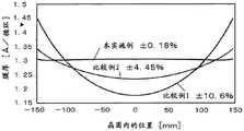
图6是表示分别使用本公开的一实施方式(本实施例)的基板处理装置、比较例1的基板处理装置、以及比较例2的基板处理装置而在基板上形成的膜的面内膜厚分布的解析结果的图。6 shows in-plane film thicknesses of films formed on substrates using the substrate processing apparatus according to one embodiment of the present disclosure (this example), the substrate processing apparatus according to Comparative Example 1, and the substrate processing apparatus according to Comparative Example 2, respectively. A graph of the analytical results of the distribution.
图7中的(A)是表示使用比较例2的基板处理装置在基板上形成膜的情况下的对流喷嘴中的惰性气体的流量与面内膜厚分布的关系的图。图7中的(B)是表示使用本公开的一实施方式的基板处理装置在基板上形成膜的情况下的对流喷嘴中的惰性气体的流量与面内膜厚分布的关系的图。FIG. 7(A) is a diagram showing the relationship between the flow rate of the inert gas in the convection nozzle and the in-plane film thickness distribution when a film is formed on a substrate using the substrate processing apparatus of Comparative Example 2. 7(B) is a diagram showing the relationship between the flow rate of the inert gas in the convection nozzle and the in-plane film thickness distribution when a film is formed on a substrate using the substrate processing apparatus according to the embodiment of the present disclosure.
具体实施方式Detailed ways
以下,使用图1~图4对本公开的一个实施方式进行说明。但是,在以下的说明中,有时对相同的结构要素标注相同的附图标记并省略重复的说明。Hereinafter, one embodiment of the present disclosure will be described with reference to FIGS. 1 to 4 . However, in the following description, the same components are denoted by the same reference numerals, and overlapping descriptions may be omitted.
(1)基板处理装置的结构(1) Structure of a substrate processing apparatus
如图1所示,处理炉202具有作为加热单元(加热机构)的加热器207。加热器207为圆筒形状,通过被保持板支承的方式而被垂直地安装。加热器207还作为使气体热活化(激发)的活化机构(激发部)而发挥功能。As shown in FIG. 1 , the
在加热器207的内侧,与加热器207呈同心圆状地配置有反应管203。反应管203由例如石英(SiO2)或碳化硅(SiC)等耐热性材料构成,形成为上端封闭且下端开口的圆筒形状。在反应管203的下方,与反应管203呈同心圆状地配置有歧管209。歧管209例如由镍合金等金属构成,形成为上端和下端开口的短的圆筒形。歧管209的上端部与反应管203的下端部卡合,对反应管203进行支承。在歧管209与反应管203之间设置有作为密封部件的O形环220a。反应管203与加热器207同样地被垂直地安装。主要由反应管203和歧管209构成处理容器(反应容器)。在处理容器的内部形成有处理室201。处理室201构成为能够收容作为基板的晶圆200。Inside the
在处理室201中,以贯通歧管209的侧壁的方式分别设置有作为第一气体喷嘴的供给成膜气体(处理气体)的喷嘴249a、作为第二气体喷嘴的供给成膜气体(处理气体)的喷嘴249b、作为第三气体喷嘴的供给惰性气体的喷嘴249c、作为第四气体喷嘴的供给惰性气体的喷嘴249d。在喷嘴249a~249d上分别连接有气体供给管232a~232d。In the
喷嘴249a和喷嘴249b被用作向处理室201供给成膜气体(处理气体)的处理气体喷嘴。另外,喷嘴249c和喷嘴249b被用作向处理室201供给惰性气体的惰性气体喷嘴。喷嘴249c和喷嘴249d分别被用作从与成膜气体不同的系统仅供给惰性气体的对流喷嘴。对流喷嘴在处理室201配置有2根。对流喷嘴分别被配置为与处理气体喷嘴在晶圆200的周向上隔开预定距离。The
在气体供给管232a~232d上,从气流的上游侧起依次分别设置有作为流量控制器(流量控制部)的质量流量控制器(MFC)241a~241d以及作为开闭阀的阀243a~243d。在气体供给管232a、232b的阀243a、243b的下游侧分别连接有供给惰性气体的气体供给管232e、232f。在气体供给管232e、232f上,从气流的上游侧起依次分别设置有MFC241e、241f及阀243e、243f。Mass flow controllers (MFCs) 241a to 241d serving as flow controllers (flow rate controllers) and
在反应管203中形成有:第一突出部302,其以收容喷嘴249a和喷嘴249b的方式向外侧突出;第二突出部303,其以收容喷嘴249c的方式向外侧突出;以及第三突出部304,其以收容喷嘴249d的方式向外侧突出。第一突出部302也可以被分割成多个,以便分别收容喷嘴249a和喷嘴249b。Formed in the
第一突出部302形成在与排气口233相对的位置。第二突出部303和第三突出部304分别形成在与第一突出部302在反应管203的周向上隔开预定距离的位置。在此,预定距离是指在反应管203的周向上从第一突出部302起15°以上且120°以下的范围内的圆弧的距离。换言之,将反应管203的第一突出部302的中心与晶圆200中心连接的直线与将第二突出部303、第三突出部304各自的中心与晶圆200中心连接的直线所成的角θ分别为15°以上且120°以下的范围内的圆弧的距离。第二突出部303和第三突出部304相对于将第一突出部302的中心与排气口233的中心连接的直线线对称地配置。The
在图2所示的例子中,第二突出部303、第三突出部304分别形成在反应管203的周向上从第一突出部302起隔开90°的位置。即,第二突出部303形成在与第三突出部304对置的位置。In the example shown in FIG. 2 , the second protruding
第一突出部302构成为在内部构成处理室201的一部分,并收容喷嘴249a、249b。第二突出部303构成为在内部构成处理室201的一部分,并收容喷嘴249c。第三突出部304构成为在内部构成处理室201的一部分,并收容喷嘴249d。The
如图2所示,在第一突出部302内从反应管203的下方向着上方沿着晶圆200的排列方向分别设置喷嘴249a和喷嘴249b。喷嘴249a和喷嘴249b在第一突出部302内相邻配置。喷嘴249a、249b以隔着被搬入处理室201内的晶圆200的中心并与后述的排气口233对置的方式配置。As shown in FIG. 2 ,
如图2所示,在第二突出部303和第三突出部304内,从反应管203的下方朝向上方沿着晶圆200的排列方向分别设置喷嘴249c和喷嘴249d。即,喷嘴249c和喷嘴249d被设置在与喷嘴249a、249b在被搬入的晶圆200的周向上分别保持预定距离的位置。在此,预定距离是指反应管203的内壁面与晶圆200的周缘部之间的距离即间隙G的一倍以上的圆弧的距离,且是在被搬入的晶圆200的周向上从喷嘴249a、249b起15°以上且120°以下的范围内的圆弧的距离。换言之,是将处理气体喷嘴的中心与晶圆200中心连接的直线、与将喷嘴249c、喷嘴249d各自的中心与晶圆200中心连接的直线所成的角θ分别为15°以上且120°以下的范围内的圆弧的距离。即,喷嘴249c、249d在被搬入的晶圆200的周向上与喷嘴249a、249b相距间隙G的一倍以上的圆弧的距离,且被配置在被搬入的晶圆200的周向上从将处理气体喷嘴的中心与晶圆中心连接的直线起15°以上120°以下的位置。另外,喷嘴249c和喷嘴249d被配置为相对于将处理气体喷嘴的中心和排气口233的中心连接的直线呈线对称。即,喷嘴249d被设置于将连接处理气体喷嘴的中心与排气口233的中心的线作为直线而划分的区域中的、设置有喷嘴249c的区域的相反侧的区域。在此,处理气体喷嘴的中心是指喷嘴249a的中心、喷嘴249b的中心、或者喷嘴249a的中心与喷嘴249b的中心的中间点。As shown in FIG. 2 , in the second protruding
在此,从喷嘴249a~249d供给的气体分别发生向着气体供给孔250a~250d所朝向的方向喷出气体的吹出和在其周围流动的吸入,由此,涡流进行循环。若将喷嘴249c、249d配置在从将处理气体喷嘴的中心与晶圆中心连接的直线起在晶圆200的周向上小于15°的位置,则喷嘴249a、249b与喷嘴249c、249d分别接近,从喷嘴249a、249b供给的处理气体的涡流与从喷嘴249c、249d供给的惰性气体的涡流合流。即,处理气体被从喷嘴249c、249d供给的惰性气体稀释。Here, the gas supplied from the
另外,若将喷嘴249c、249d配置在从将处理气体喷嘴的中心与晶圆中心连接的直线起在被搬入的晶圆200的周向上大于120°的位置,则从喷嘴249a、249b供给的处理气体与从喷嘴249c、249d供给的惰性气体能够干扰的范围变小,因此不会对晶圆200上造成影响,由惰性气体的涡流产生的影响程度减弱。因此,喷嘴249c、249d优选被配置在与喷嘴249a、249b保持间隙G的一倍以上的圆弧的距离的位置,且是在从将处理气体喷嘴的中心与晶圆中心连接的直线起在被搬入的晶圆200的周向上15°以上且120°以下的位置。In addition, if the
在喷嘴249a~249d的侧面分别设置有供给气体的气体供给孔250a~250d。气体供给孔250a、250b能够分别朝向晶圆200的中心方向供给气体。气体供给孔250a、250b以从反应管203的下部到上部朝向各个晶圆200的中心开口的方式被设置为多个。
气体供给孔250c、250d能够分别向喷嘴249a、249b供给惰性气体。即,气体供给孔250c、250d以从反应管203的下部遍及上部分别朝向喷嘴249a、249b开口的方式被设置为多个。The
具体而言,气体供给孔250c、250d分别形成为从晶圆中心起例如45°朝向喷嘴249a、249b侧进行开口,并形成为能够朝向掠过第一突出部302的壁的方向供给惰性气体。即,气体供给孔250c、250d形成为从反应管203的下部到上部分别从晶圆中心起例如45°朝向喷嘴249a、249b侧进行开口,以朝向第一突出部302的壁的内侧进行开口的方式被设置为多个,以便能够朝向掠过第一突出部302的壁的方向供给惰性气体。通过从该气体供给孔250c、250d供给惰性气体,在第二突出部303、第三突出部304附近分别形成惰性气体的涡流,该惰性气体的涡流阻止从间隙G区域的上游侧流动的处理气体的流动。即,阻止在间隙G区域的上游侧流动的处理气体向间隙G区域的下游侧流入。另外,在间隙G区域的上游侧流动的处理气体通过惰性气体的涡流而不与惰性气体混合,朝向晶圆200中心方向流入。Specifically, the
在此,若使气体供给孔250c、250d的朝向比掠过壁的方向更靠向喷嘴249a、249b侧,则从喷嘴249c、249d供给的惰性气体将在第一突出部302内碰撞,使惰性气体的涡流的直径变小,从而使上述效果减弱。另外,若使气体供给孔250c、250d的朝向比掠过壁的方向更靠向与喷嘴249a、249b相反的一侧(排气侧),则惰性气体被卷入第一突出部302侧的涡流而与处理气体混合,因此上述的效果将减弱。Here, if the
从气体供给管232a经由MFC241a、阀243a、喷嘴249a向处理室201供给例如包含作为预定元素(主元素)的Si及卤素元素的卤代硅烷类气体来作为原料气体(处理气体)。As a raw material gas (processing gas), a halosilane-based gas containing Si as a predetermined element (main element) and a halogen element, for example, is supplied from the
从气体供给管232b经由MFC241b、阀243b、喷嘴249b向处理室201供给例如作为氮化气体的氮化氢类气体来作为处理气体且与所述原料的化学结构(分子结构)不同的反应体(反应物)。氮化氢类气体被用作N源。作为氮化氢类气体,例如可以使用氨(NH3)气。From the
从气体供给管232c~232f分别经由MFC241c~241f、阀243c~243f、气体供给管232c、232d、232a、232b、喷嘴249c、249d、249a、249b向处理室201供给例如氮(N2)气体来作为惰性气体。N2气体作为吹扫气体、载气而起作用,进而作为对形成于晶圆200上的膜的面内膜厚分布进行控制的膜厚分布控制气体来起作用。For example, nitrogen (N2 ) gas is supplied to the
主要由气体供给管232a、232b、MFC241a、241b、阀243a、243b构成处理气体供给系统。另外,主要由气体供给管232c~232f、MFC241c~241f、阀243c~243f构成惰性气体供给系统。The process gas supply system is mainly composed of
在反应管203设置有作为对处理室201的气氛进行排气的排气部的排气口233。如图2所示的水平剖视图那样,排气口233被设置在隔着晶圆200并与喷嘴249a、249b(气体供给孔250a、250b)对置(面对)的位置。在排气口233连接有排气管231。排气管231具备作为检测处理室201的压力的压力检测器的压力传感器245,另外,经由作为压力调整器的APC(Auto Pressure Controller,自动压力控制器)阀244与真空泵(真空排气装置)246连接。APC阀244被构成为通过在使真空泵246工作的状态下对阀开闭,能够进行处理室201的真空排气以及真空排气停止,而且在使真空泵246工作的状态下,基于由压力传感器245检测出的压力信息来调节开度,由此能够调整处理室201的压力。主要由排气管231、APC阀244、压力传感器245构成排气系统。真空泵246也可以包含在排气系统中。The
在歧管209的下方设置有能够气密地封闭歧管209的下端开口的作为炉口盖体的密封盖219。密封盖219例如为金属制,并形成为圆盘状。在密封盖219的上表面设置有与歧管209的下端抵接的作为密封部件的O形环220b。在密封盖219的下方设置有使后述的晶舟217旋转的旋转机构267。旋转机构267的旋转轴255贯通密封盖219而与晶舟217连接。旋转机构267通过使晶舟217旋转而使晶圆200旋转。Below the manifold 209, a sealing
密封盖219构成为通过作为设置于反应管203的外部的升降机构的晶舟升降机115在垂直方向上升降。晶舟升降机115构成为通过使密封盖219升降而将晶圆200搬入及搬出(搬送)到处理室201内外的搬送装置(搬送机构)。另外,在歧管209的下方或侧方设置有在使密封盖219下降而将晶舟217完全从处理室201内搬出的期间,气密地闭塞歧管209的下端开口的作为炉口盖体的闸门221。闸门221与密封盖219同样地形成为圆盘状,在其上表面设置有与歧管209的下端抵接的O形环220c。闸门221的开闭动作(升降动作、转动动作等)由闸门开闭机构222控制。The sealing
作为基板支承件的晶舟217被构成为将多片、例如25~200片晶圆200以水平姿势且彼此中心对齐的状态下沿垂直方向排列而多层地支承,即隔开间隔地排列。晶舟217例如由石英、SiC等耐热性材料构成。在晶舟217的下部,多层地支承有例如由石英、SiC等耐热性材料构成的隔热板218。The
在反应管203内设置有作为温度检测器的温度传感器263。通过基于由温度传感器263检测出的温度信息来调整向加热器207的通电情况,处理室201的温度成为所希望的温度分布。温度传感器263沿着反应管203的内壁设置。A
如图3所示,作为控制部(控制单元)的控制器121构成为具备CPU(CentralProcessing Unit,中央处理器)121a、RAM(Random Access Memory,随机存取存储器)121b、存储装置121c、I/O端口121d的计算机。RAM121b、存储装置121c、I/O端口121d构成为能够经由内部总线121e与CPU121a进行数据交换。控制器121与例如构成为触摸面板等的输入输出装置122连接。As shown in FIG. 3 , the
存储装置121c例如由闪存、HDD(Hard Disk Drive,硬盘驱动器)等构成。在存储装置121c内,以能够读出的方式存储有对基板处理装置的动作进行控制的控制程序、记载有后述的基板处理的步骤或条件等的工艺制程等。工艺制程是以能够使控制器121执行后述的基板处理中的各步骤并得到预定的结果的方式组合而成的,作为程序发挥功能。以下,将工艺制程、控制程序等总称为程序。另外,也将工艺制程简称为制程。在本说明书中使用程序这样的用语的情况下,有时仅包含制程单体、仅包含控制程序单体、或者包含这两者。RAM121b构成为暂时保持由CPU121a读取的程序、数据等的存储器区域(工作区域)。The
I/O端口121d与上述MFC241a~241f、阀243a~243f、压力传感器245、APC阀244、真空泵246、温度传感器263、加热器207、旋转机构267、晶舟升降机115、闸门开闭机构222等连接。The I/
CPU121a构成为从存储装置121c读取控制程序并执行,并且根据来自输入输出装置122的操作命令的输入等,从存储装置121c读取制程。CPU121a构成为按照读出的制程的内容,控制利用MFC241a~241f进行的各种气体的流量调整动作、阀243a~243f的开闭动作、APC阀244的开闭动作及基于压力传感器245的APC阀244的压力调整动作、真空泵246的启动及停止、基于温度传感器263的加热器207的温度调整动作、利用旋转机构267进行的晶舟217的旋转及旋转速度调节动作、利用晶舟升降机115进行的晶舟217的升降动作、利用闸门开闭机构222进行的闸门221的开闭动作等。The
控制器121能够通过将存储于外部存储装置(例如硬盘等磁盘、CD等光盘、MO等光磁盘、USB存储器等半导体存储器)123的上述程序安装于计算机而构成。存储装置121c、外部存储装置123构成为计算机可读取的记录介质。以下,也将它们总称为记录介质。在本说明书中使用了记录介质这样的用语的情况下,有时仅包含存储装置121c单体、仅包含外部存储装置123单体、或者包含这两者。此外,向计算机的程序的提供也可以不使用外部存储装置123,而使用因特网、专用线路等通信手段来进行。The
(2)成膜处理(2) Film formation treatment
使用图4对使用上述的基板处理装置,作为半导体装置的制造工序的一个工序,在作为基板的晶圆200上形成氮化硅膜(SiN膜)的顺序例进行说明。在以下的说明中,构成基板处理装置的各部的动作由控制器121控制。An example of a procedure for forming a silicon nitride film (SiN film) on a
图4所示的成膜顺序通过对不同时进行步骤A和步骤B的循环执行n次(n为预定数),从而在晶圆200上形成包含Si和N的膜、即SiN膜。The film formation sequence shown in FIG. 4 forms a film containing Si and N, that is, a SiN film, on the
步骤A通过从喷嘴249a对晶圆200供给HCDS气体来形成作为第一层的含Si层;Step A forming a Si-containing layer as the first layer by supplying HCDS gas to the
步骤B通过从喷嘴249b对晶圆200供给NH3气体来形成作为第二层的氮化硅层(SiN层)。Step B is to form a silicon nitride layer (SiN layer) as a second layer by supplying NH3 gas to the
在本说明书中,为了方便,有时也如下那样表示图4所示的成膜顺序。In this specification, for the sake of convenience, the film forming sequence shown in FIG. 4 may be shown as follows.

在本说明书中使用“晶圆”这一用语的情况下,有时指晶圆本身,有时指晶圆与其表面上形成的预定的层或膜的层叠体。在本说明书中使用“晶圆的表面”这一用语的情况下,有时指晶圆本身的表面,有时指形成于晶圆上的预定的层等的表面。在本说明书中,“基板”包含“晶圆”的含义。When the term "wafer" is used in this specification, the wafer itself may be referred to, or the wafer and a laminate of a predetermined layer or film formed on the surface thereof may be referred to. When the term "the surface of a wafer" is used in this specification, the surface of the wafer itself may be referred to, and the surface of a predetermined layer or the like formed on the wafer may be referred to. In this specification, "substrate" includes the meaning of "wafer".
(晶圆供给和晶舟装载)(Wafer supply and boat loading)
当将多片晶圆200装填(晶圆供给)到晶舟217时,闸门221通过闸门开闭机构222移动,歧管209的下端开口开放(闸门打开)。之后,如图1所示,支承多片晶圆200的晶舟217被晶舟升降机115抬起而向处理室201搬入(晶舟装载)。在搬入完成后,密封盖219成为经由O型环220b将歧管209的下端密封的状态。When a plurality of
(压力调整及温度调整)(Pressure adjustment and temperature adjustment)
通过真空泵246对处理室201进行真空排气(减压排气),以使处理室201、即存在晶圆200的空间成为所希望的压力(真空度)。此时,处理室201的压力由压力传感器245测定,基于该测定出的压力信息对APC阀244进行反馈控制。另外,通过加热器207进行加热,以使处理室201的晶圆200成为所希望的成膜温度。此时,基于温度传感器263检测出的温度信息对向加热器207的通电情况进行反馈控制,以使处理室201成为期望的温度分布。另外,开始利用旋转机构267进行的晶圆200的旋转。处理室201的排气、晶圆200的加热及旋转均至少在对晶圆200的处理结束之前的期间持续进行。The
(成膜步骤)(film formation step)
然后,依次执行接下来的步骤A、B。Then, the next steps A and B are performed in sequence.
[步骤A][Step A]
在该步骤中,对处理室201的晶圆200供给HCDS气体。In this step, the HCDS gas is supplied to the
具体而言,打开阀243a,使HCDS气体向气体供给管232a内流动。HCDS气体通过MFC241a进行流量调整,经由喷嘴249a向处理室201内供给,从排气口233排出。即,对晶圆200供给HCDS气体。此时,也可以打开阀243e,使N2气体向气体供给管232e内流动。N2气体通过MFC241e进行流量调整,与HCDS气体一起经由喷嘴249a向处理室201供给,能够从排气口233排出。此外,在步骤A中,在经由喷嘴249a向处理室201供给HCDS气体的状态下,经由喷嘴249c、249d分别向处理室201供给N2气体。以使在第二突出部303、第三突出部304附近分别形成惰性气体的涡流的方式,将从喷嘴249c、249d供给的N2气体朝向喷嘴249a供给。其详细情况将在后面叙述。Specifically, the
在步骤A中,从喷嘴249a供给的HCDS气体的流量例如为1sccm以上且2000sccm以下,优选为10sccm以上且1000sccm以下的范围内。另外,从喷嘴249c、249d供给的N2气体的流量例如分别为500sccm,设为包含从喷嘴249a供给的N2气体的HCDS气体的总流量的约1/4以上且2/3以下的预定的流量。In step A, the flow rate of the HCDS gas supplied from the
相对于从喷嘴249a供给的HCDS气体的总流量,在从喷嘴249c、249d供给的N2气体的流量少于HCDS气体的总流量的1/4的情况下,从喷嘴249c、249d供给的N2气体被HCDS气体推开。即,在间隙G区域流动的原料气体不被稀释而向下游侧流动,到达晶圆200中心的原料气体的总量减少。即,形成在晶圆200上的膜的膜厚分布成为凹状,面内膜厚均匀性恶化。With respect to the total flow rate of the HCDS gas supplied from the
另外,相对于从喷嘴249a供给的HCDS气体的总流量,在从喷嘴249c、249d供给的N2气体的流量多于HCDS气体的总流量的2/3的情况下,通过从喷嘴249c、249d供给的N2气体,在间隙G区域流动的原料气体的稀释效果变大,到达晶圆中心的原料气体的总量过度增加。即,形成在晶圆200上的膜的膜厚分布成为凸状,面内膜厚均匀性恶化。In addition, when the flow rate of the
因此,使从喷嘴249c、249d供给的N2气体的流量成为包含从喷嘴249a供给的N2气体的HCDS气体的总流量的约1/4~2/3的预定的流量。此外,这些流量条件根据晶圆200的表面积、晶圆间距、间隙G的宽度、喷嘴249c、249d的位置、喷嘴249c、249d的气体供给孔250c、250d的朝向、气体种类、成膜温度、处理压力等而不同。Therefore, the flow rate of the N2 gas supplied from the
HCDS气体的供给时间例如为1秒以上且120秒以下,优选1秒以上且60秒以下的范围内的预定时间。处理室201的压力为例如1Pa以上且2666Pa以下,优选67Pa以上且1333Pa以下的范围内的预定的压力。晶圆200的温度(成膜温度)例如为250℃以上且800℃以下,优选400℃以上且750℃以下,更优选550℃以上且700℃以下的范围内的预定温度。The supply time of the HCDS gas is, for example, 1 second or more and 120 seconds or less, preferably a predetermined time in the range of 1 second or more and 60 seconds or less. The pressure of the
通过在上述条件下对晶圆200供给HCDS气体和N2气体,在晶圆200的最表面上形成含有例如从小于1原子层至多原子层(从小于1分子层至多分子层)左右的厚度的Cl的含Si层作为第一层。包含Cl的含Si层可以是包含Cl的Si层,也可以是HCDS的吸附层,还可以包含它们双方。By supplying the HCDS gas and the N2 gas to the
在HCDS气体自分解(热分解)的条件下,通过在晶圆200上堆积Si而形成包含Cl的Si层。在HCDS气体不发生自分解(热分解)的条件下,通过HCDS吸附于晶圆200上而形成HCDS的吸附层。与形成HCDS的吸附层相比,以成膜速率的观点考虑,优选形成含有Cl的Si层。以下,为了方便,也将含Cl的含Si层简称为含Si层。The Si layer containing Cl is formed by depositing Si on the
在步骤A中,在从喷嘴249a供给HCDS气体的状态下打开阀243c~243f,向气体供给管232c、232d、232b内流动N2气体,从喷嘴249c、249d、249b向处理室201内供给N2气体。维持从喷嘴249b供给少量的N2气体的方式不是必须的,但在抑制HCDS气体向喷嘴249b内侵入的观点下是优选的。出于该目的,来自喷嘴249b的N2气体的供给优选与步骤A同时或者在此之前开始。In step A, the
在步骤A中,从喷嘴249a、249b供给的N2气体的各流量(第一流量)分别为比从喷嘴249c、249d供给的N2的流量小的流量。进而,对于从喷嘴249c、249d供给的N2气体的各流量,使它们的合计流量成为如下这样的流量,即比从喷嘴249a供给的HCDS气体和N2气体的总流量小的流量。In step A, each flow rate (first flow rate) of the N2 gas supplied from the
在形成具有所希望的厚度及面内厚度分布的第一层后关闭阀243a,停止HCDS气体的供给。此时,APC阀244保持打开的状态,利用真空泵246对处理室201内进行真空排气,将残留在处理室201内的未反应或有助于第一层的形成后的HCDS气体从处理室201内排除。从喷嘴249a~249d供给的N2气体作为吹扫气体而起作用,由此,对处理室201内进行吹扫(吹扫步骤)。After the first layer having the desired thickness and in-plane thickness distribution is formed, the
[步骤B][Step B]
在步骤A结束后,对处理室201内的晶圆200、即形成于晶圆200上的第一层供给NH3气体。After step A is completed, NH3 gas is supplied to the
在该步骤中,以与步骤A中的阀243a、243c~243f的开闭控制相同的顺序进行阀243b、243c~243f的开闭控制。NH3气体通过MFC241b进行流量调整,经由喷嘴249b向处理室201内供给,从排气口233排出。此时,对晶圆200供给NH3气体。In this step, the opening and closing control of the
在步骤B中,从喷嘴249b供给的NH3气体的供给流量为例如1000~10000sccm的范围内的预定的流量。此时,从喷嘴249c、249d供给的N2气体的流量为包含从喷嘴249b供给的N2气体的NH3气体的总流量的约1/4以上且2/3以下的预定的流量。通过这样设定,能够得到与在上述的步骤A中说明的效果同样的效果。In step B, the supply flow rate of the NH3 gas supplied from the
NH3气体的供给时间设为例如1秒以上且120秒以下、优选为1秒以上且60秒以下的范围内的预定时间。处理室201的压力为例如1Pa以上且4000Pa以下、优选1Pa以上且3000Pa以下的范围内的预定压力。通过设为比步骤A高的压力,即使不使用等离子体而是使用了热活化的NH3气体,也能够以预定的速度与第一层进行化学反应,形成第二层。其他处理条件设为与步骤A同样的处理条件。另外,在步骤B中,与步骤A相比,来自喷嘴249c、249d的N2气体供给的重要性低,也有时不需要。The supply time of the NH3 gas is, for example, a predetermined time in the range of 1 second or more and 120 seconds or less, preferably 1 second or more and 60 seconds or less. The pressure of the
在上述条件下对晶圆200供给NH3气体和N2气体时,形成于晶圆200上的第一层的至少一部分被氮化(改性)。由此,在晶圆200上形成包含Si和N的第二层、即SiN层。在形成第二层时,第一层中所含的Cl等杂质在利用NH3气体进行的第一层的改性反应的过程中,构成至少包含Cl的气体状物质,并从处理室201排出。即,第一层中的Cl等杂质从第一层中被抽出或脱离,由此从第一层分离。由此,第二层成为Cl等杂质比第一层少的层。When the NH3 gas and the N2 gas are supplied to the
在形成了第二层之后,关闭阀243b,停止NH3气体的供给。然后,通过与步骤A的吹扫步骤同样的处理步骤、处理条件,从处理室201内排除残留于处理室201内的未反应或有助于第二层的形成后的NH3气体、反应副产物。After the formation of the second layer, the
[预定次数实施][Predetermined number of implementations]
通过将不同时地进行、即不同步地进行步骤A、B的循环执行1次以上(n次),能够在晶圆200上形成预定组成及预定膜厚的SiN膜。上述循环优选重复多次。即,在执行1次上述的循环时形成的第二层的厚度比期望的膜厚薄,优选反复执行多次上述的循环,直至通过层叠第二层而形成的SiN膜的膜厚达到期望的膜厚。A SiN film having a predetermined composition and predetermined film thickness can be formed on the
(后吹扫~大气压恢复)(Post-purge ~ Atmospheric pressure recovery)
在晶圆200上形成了期望组成、期望膜厚的膜后,从喷嘴249a~249d分别向处理室201供给作为吹扫气体的N2气体,并从排气口233排气。由此,对处理室201进行吹扫,将残留于处理室201内的气体、反应副产物从处理室201除去(后吹扫)。之后,处理室201的气氛被置换为惰性气体(惰性气体置换),处理室201的压力恢复为常压(大气压恢复)。After a film of a desired composition and desired film thickness is formed on the
(晶舟卸载及晶圆卸载)(boat unloading and wafer unloading)
通过晶舟升降机115使密封盖219下降,歧管209的下端开口。然后,处理完毕的晶圆200在被晶舟217支承的状态下从歧管209的下端向反应管203的外部搬出(晶舟卸载)。在晶舟卸载之后,使闸门221被移动,歧管209的下端开口经由O形环220c被闸门221密封(闸门关闭)。处理完毕的晶圆200在被搬出至反应管203的外部之后,从晶舟217被取出(晶圆卸载)。The sealing
(3)模拟(3) Simulation
使用上述图1所示的基板处理装置的处理炉202,进行图4所示的成膜顺序中的处理,在裸晶圆的70倍的表面积的图案晶圆上形成SiN膜。图5中的(A)是表示图4所示的成膜顺序中的步骤A时的处理炉202内的原料自由基的浓度分布的图,图5中的(B)是表示图5中的(A)中的第二突出部303附近的气体的流动的图。Using the
如图5中的(A)所示,喷嘴249c、249d的气体供给孔250c、250d分别朝向将处理气体喷嘴侧的N2气体朝向掠过第一突出部302的壁部的方向,而不是朝向晶圆中心方向。此外,喷嘴249d是与喷嘴249c相同的结构,起到同样的效果,因此以下使用喷嘴249c来进行说明。As shown in (A) of FIG. 5 , the
在本模拟中,从喷嘴249a供给的原料气体即HCDS气体的流量为200sccm,从喷嘴249a供给的N2气体的流量为12000sccm。此时,同时从喷嘴249c、249d分别供给的N2气体的流量为6250sccm。此时的处理室201内的压力设为140Pa,成膜温度设为700℃,其他处理条件设为与上述的步骤A同样的条件。In this simulation, the flow rate of the HCDS gas, which is the raw material gas supplied from the
在此,在大表面积的晶圆上形成膜的情况下,从喷嘴249a供给的原料气体的大半在晶圆200的周缘部与反应管203的内壁之间的间隙G区域流动,而不是在狭窄的晶圆200间(晶圆间距间)流动。由此,原料气体在晶圆周缘部扩散,在晶圆上流动的原料气体的总量减少,到达晶圆中心部的原料气体枯竭。另外,通过在间隙G区域流动的原料气体使晶圆的周缘部膜厚度增加,结果是在晶圆上形成凹状的膜。Here, when a film is formed on a wafer with a large surface area, most of the source gas supplied from the
如本实施方式那样,当从喷嘴249c供给的N2气体朝向喷嘴249a向着掠过第一突出部302的壁的方向供给时,如图5中的(B)所示,在与第二突出部303附近的晶圆200的周缘部的一部分重叠的位置形成惰性气体(N2气体)的涡流。通过该惰性气体的涡流,在间隙G区域流动的原料气体在第二突出部303附近被阻挡,能够使原料气体不会流向比喷嘴249c更靠下游侧的间隙G区域。这样,在晶圆200的周缘部的一部分,原料气体的浓度降低而被稀释。其结果是抑制了晶圆200的周缘部的膜厚度增加。As in the present embodiment, when the N2 gas supplied from the
另外,通过该惰性气体的涡流,在第二突出部303附近被阻挡的原料气体不与N2气体混合,而被朝向晶圆200中心方向引导。该惰性气体的涡流与原料气体不混合而排斥,原料气体的流动方向变化为惰性气体的涡流的流动方向。即,向晶圆200中心部供给原料气体而使晶圆200中心部膜厚度增加。In addition, by the eddy current of the inert gas, the raw material gas blocked in the vicinity of the second protruding
另外,从喷嘴249c供给的N2气体通过该惰性气体的涡流分别朝向排气口233而在下游侧的间隙G区域流动并被排出。即,第二突出部303的下游侧的间隙G区域被N2气体稀释,抑制晶圆200的周缘部的膜厚度增加。In addition, the N2 gas supplied from the
即,通过利用喷嘴249c、249d的惰性气体的供给来形成惰性气体的涡流,由此能够调整晶圆200上的原料气体的稀释效果范围。That is, by supplying the inert gas from the
另外,惰性气体的涡流的大小能够通过调整喷嘴249c、249d的位置、喷嘴249c、249d的气体供给孔250c、250d的朝向、反应管203的壁面形状、或者相对于原料气体的总流量的从喷嘴249c、249d供给的惰性气体的流量来进行控制。因此,能够通过从晶圆的周缘部到任意距离的稀释来控制膜厚。In addition, the size of the vortex of the inert gas can be adjusted by adjusting the positions of the
因此,能够控制面内膜厚分布,即使在处理表面积大的图案晶圆中也能够提高膜厚面内均匀性。Therefore, the in-plane film thickness distribution can be controlled, and the in-plane uniformity of the film thickness can be improved even in a patterned wafer with a large processing surface area.
以下,对实施例进行说明。Hereinafter, Examples will be described.
实施例1Example 1
图6中的本实施例对使用图1及图2所示的基板处理装置,通过图4所示的成膜顺序形成有SiN膜的晶圆的面内膜厚均匀性进行了评价。图6中的比较例1对使用在处理室中没有对流喷嘴的基板处理装置形成有SiN膜的晶圆的面内膜厚均匀性进行了评价。图6中的比较例2对使用在处理室中具有2根对流喷嘴的基板处理装置来形成有SiN膜的晶圆的面内膜厚均匀性进行了评价。在比较例2中,2根对流喷嘴分别被配置在晶圆200的周向上从处理气体喷嘴离开90°的位置,各对流喷嘴的气体供给孔朝向晶圆200的中心。In this example shown in FIG. 6 , the in-plane film thickness uniformity of the wafer on which the SiN film was formed by the film formation sequence shown in FIG. 4 was evaluated using the substrate processing apparatus shown in FIGS. 1 and 2 . Comparative Example 1 in FIG. 6 evaluated the in-plane film thickness uniformity of a wafer formed with a SiN film using a substrate processing apparatus without a convection nozzle in the processing chamber. Comparative Example 2 in FIG. 6 evaluated the in-plane film thickness uniformity of a wafer on which a SiN film was formed using a substrate processing apparatus having two convection nozzles in a processing chamber. In Comparative Example 2, the two convection nozzles were respectively arranged at positions 90° away from the processing gas nozzles in the circumferential direction of the
由本实施例形成的晶圆的面内膜厚均匀性为±0.18%,由比较例1形成的晶圆的面内膜厚均匀性为±10.6%,由比较例2形成的晶圆的面内膜厚均匀性为±4.45%。The in-plane film thickness uniformity of the wafer formed by this example is ±0.18%, the in-plane film thickness uniformity of the wafer formed by Comparative Example 1 is ±10.6%, and the in-plane film thickness uniformity of the wafer formed by Comparative Example 2 The film thickness uniformity was ±4.45%.
在没有对流喷嘴的比较例1中,与使用了对流喷嘴的比较例2、本实施例相比,确认了晶圆的周缘部(两端部)的膜厚比晶圆的中心部的膜厚形成得厚,面内膜厚均匀性差。另外,在本实施例的使用了对流喷嘴的情况下,与比较例2的使用了对流喷嘴的情况相比,确认了晶圆200的周缘部(两端部)处的膜厚度增加被抑制,面内膜厚均匀性得到改善。In Comparative Example 1 without a convection nozzle, compared with Comparative Example 2 and this Example using a convection nozzle, it was confirmed that the film thickness of the peripheral portion (both ends) of the wafer was larger than the film thickness of the central portion of the wafer. Formed thick, the in-plane film thickness uniformity is poor. In addition, in the case of using the convection nozzle of the present example, compared with the case of using the convection nozzle of Comparative Example 2, it was confirmed that the increase in the film thickness at the peripheral edge portion (both ends) of the
在比较例2中,由侧边对流装置供给的N2气体与原料气体混合,晶圆周缘部的原料气体的稀释效果减弱。另外,原料气体被稀释,从而到达晶圆中心部的原料气体的总量减少。进而,原料气体向下游侧的间隙G区域流出,通过该流出的原料气体的扩散,晶圆周缘部膜厚度增加。其结果是面内膜厚分布成为凹状。In Comparative Example 2, the N2 gas supplied from the side convection device was mixed with the raw material gas, and the dilution effect of the raw material gas in the peripheral portion of the wafer was weakened. In addition, the raw material gas is diluted, and the total amount of the raw material gas reaching the center of the wafer is reduced. Furthermore, the raw material gas flows out to the gap G region on the downstream side, and the film thickness of the wafer peripheral portion increases due to the diffusion of the flowing raw material gas. As a result, the in-plane film thickness distribution becomes concave.
与此相对,在本实施例中,通过由侧边对流装置供给的N2气体形成的惰性气体的涡流不与原料气体混合而变更在间隙G区域流动的原料气体的流动。由此,在间隙G区域流动的原料气体的浓度降低,晶圆周缘部的膜厚度增加被抑制。另外,通过该惰性气体的涡流,在间隙G区域流动的原料气体被朝向晶圆中心方向引导,到达晶圆中心部的原料气体的流量增加。进而,通过惰性气体的涡流,下游侧的间隙G区域被稀释,晶圆200的周缘部的膜厚度增加被抑制。In contrast, in the present embodiment, the flow of the raw material gas flowing in the gap G region is changed without mixing with the raw material gas by the vortex of the inert gas formed by the N2 gas supplied from the side convection device. As a result, the concentration of the source gas flowing in the gap G region is reduced, and the increase in the film thickness of the wafer peripheral portion is suppressed. In addition, by the eddy current of the inert gas, the source gas flowing in the gap G region is guided toward the center of the wafer, and the flow rate of the source gas reaching the center of the wafer increases. Furthermore, the gap G region on the downstream side is diluted by the eddy current of the inert gas, and the increase in the film thickness of the peripheral portion of the
因此,确认了通过使对流喷嘴的气体供给孔的朝向向着比晶圆中心侧更靠处理气体喷嘴侧,从而改善了面内膜厚均匀性。Therefore, it was confirmed that the in-plane film thickness uniformity was improved by orienting the gas supply hole of the convection nozzle toward the processing gas nozzle side rather than the wafer center side.
实施例2Example 2
接着,对膜厚的对流喷嘴中的惰性气体的流量依赖性进行比较。图7中的(A)是表示上述比较例2的基于对流喷嘴的惰性气体的流量与面内膜厚分布的关系的图。图7中的(B)是表示上述本实施例的基于对流喷嘴的惰性气体的流量与面内膜厚分布的关系的图。Next, the flow rate dependence of the inert gas in the convection nozzle of the film thickness was compared. (A) of FIG. 7 is a graph showing the relationship between the flow rate of the inert gas by the convection nozzle and the in-plane film thickness distribution in the comparative example 2 described above. (B) of FIG. 7 is a diagram showing the relationship between the flow rate of the inert gas by the convection nozzle and the in-plane film thickness distribution in the present embodiment.
如图7中的(A)所示,在比较例2中,若从对流喷嘴供给的N2气体的流量少,则晶圆周缘部的膜厚度增加。这被认为是因为从对流喷嘴供给的N2气体无法使在间隙G中流动的原料气体充分地稀释,从而无法使原料气体到达晶圆中心部。另外,若增多从对流喷嘴供给的N2气体的流量,则能够使晶圆周缘部的膜厚减膜,但确认到在周缘部附近发生局部的膜厚度增加。可以认为这是由于晶圆周缘部被从对流喷嘴供给的N2气体稀释,但由于与流过间隙G的原料气体的浓度差,在周缘部附近发生浓度扩散。这样,比较例2对于周缘部附近的局部的膜厚度增加并不有效。在此,晶圆周缘部与晶圆中心的距离为80mm以上且120mm以下,晶圆周缘部附近与晶圆中心的距离为120mm以上且150mm以下。若进一步增多N2气体的流量,则确认到在晶圆中心部膜厚度增加。可以认为这是由于若从对流喷嘴供给的N2气体的流量多,则N2气体被朝向晶圆中心部供给,因此晶圆的周缘部处的原料气体被稀释,但由于从对流喷嘴供给的N2气体,间隙G的原料气体向晶圆中心部大量流动。As shown in FIG. 7(A) , in Comparative Example 2, when the flow rate of the N2 gas supplied from the convection nozzle was small, the film thickness of the wafer peripheral portion increased. This is considered to be because the N2 gas supplied from the convection nozzle cannot sufficiently dilute the raw material gas flowing in the gap G, so that the raw material gas cannot reach the center of the wafer. In addition, if the flow rate of the N2 gas supplied from the convection nozzle was increased, the film thickness of the wafer peripheral portion could be reduced, but it was confirmed that a local increase in the film thickness occurred in the vicinity of the peripheral portion. This is considered to be because the wafer peripheral portion is diluted by the N2 gas supplied from the convection nozzle, but concentration diffusion occurs in the vicinity of the peripheral portion due to the concentration difference with the raw material gas flowing through the gap G. In this way, Comparative Example 2 is not effective in increasing the local film thickness in the vicinity of the peripheral edge portion. Here, the distance between the wafer peripheral portion and the wafer center is 80 mm or more and 120 mm or less, and the distance between the wafer peripheral portion and the wafer center is 120 mm or more and 150 mm or less. When the flow rate of the N2 gas was further increased, it was confirmed that the film thickness increased at the center of the wafer. This is considered to be because when the flow rate of the N2 gas supplied from the convection nozzle is large, the N2 gas is supplied toward the central portion of the wafer, so that the raw material gas at the peripheral portion of the wafer is diluted. The N2 gas and the raw material gas in the gap G flow in a large amount to the center of the wafer.
如图7中的(B)所示,在本实施例中,确认了若增多从对流喷嘴供给的N2气体的流量,则抑制晶圆周缘部附近的局部的膜厚度增加,并且在晶圆中心部进行膜厚度增加。由此,不引起晶圆边缘的局部膜厚度增加,能够控制面内的凹凸,晶圆的面内膜厚分布不会成为W型的分布。即,确认了通过调整从对流喷嘴供给的惰性气体的流量,能够控制面内膜厚分布,提高面内膜厚均匀性。As shown in FIG. 7(B) , in this example, it was confirmed that if the flow rate of the N2 gas supplied from the convection nozzle was increased, the local film thickness increase in the vicinity of the wafer peripheral portion was suppressed, and the wafer The central portion is subjected to film thickness increase. As a result, the in-plane unevenness can be controlled without causing a local increase in the film thickness at the wafer edge, and the in-plane film thickness distribution of the wafer does not become a W-shaped distribution. That is, it was confirmed that by adjusting the flow rate of the inert gas supplied from the convection nozzle, the in-plane film thickness distribution can be controlled and the in-plane film thickness uniformity can be improved.
(4)本实施方式的效果(4) Effects of the present embodiment
根据本实施方式,能够得到以下所示的1个或多个效果。According to the present embodiment, one or more of the following effects can be obtained.
(a)在从处理气体喷嘴对晶圆供给处理气体时,从在晶圆的周向上与处理气体喷嘴偏离预定距离设置的对流喷嘴向着处理气体喷嘴供给惰性气体,从而形成惰性气体的涡流,由此能够提高形成于晶圆上的膜的面内膜厚均匀性。(a) When the process gas is supplied to the wafer from the process gas nozzle, the inert gas is supplied to the process gas nozzle from the convection nozzle provided at a predetermined distance from the process gas nozzle in the circumferential direction of the wafer, so that a vortex of the inert gas is formed by This can improve the in-plane thickness uniformity of the film formed on the wafer.
(b)通过该惰性气体的涡流,在晶圆的周缘部与反应管的内壁之间的间隙G区域流动的处理气体不与惰性气体混合而排斥,变化为惰性气体的涡流的流动方向,朝向晶圆的中心方向流动。因此,能够增加向晶圆的中心部供给的原料气体,使晶圆中心部膜厚度增加。(b) Due to the eddy current of the inert gas, the process gas flowing in the region of the gap G between the peripheral edge of the wafer and the inner wall of the reaction tube is repelled without mixing with the inert gas, and changes to the flow direction of the eddy current of the inert gas toward the Flow in the center direction of the wafer. Therefore, the raw material gas supplied to the central portion of the wafer can be increased, and the film thickness of the central portion of the wafer can be increased.
(c)另外,通过在第二突出部303、第三突出部304附近形成惰性气体的涡流,能够抑制处理气体向晶圆的周缘部与反应管的内壁之间的间隙G区域的流入,减少流向第二突出部303、第三突出部304的下游侧的间隙G区域的处理气体,抑制晶圆的周缘部的膜厚度增加。(c) In addition, by forming a vortex of the inert gas in the vicinity of the second protruding
(d)另外,通过以与晶圆的周缘部的一部分重叠的方式形成惰性气体的涡流,在晶圆的周缘部的一部分中原料气体的浓度降低并稀释。由此,能够抑制晶圆的周缘部的膜厚度增加。(d) In addition, by forming a vortex of the inert gas so as to overlap with a part of the peripheral part of the wafer, the concentration of the raw material gas is reduced and diluted in a part of the peripheral part of the wafer. Thereby, the film thickness of the peripheral part of a wafer can be suppressed from increasing.
(e)另外,通过第二突出部303、第三突出部304附近的惰性气体的涡流,由对流喷嘴供给的惰性气体朝向排气口流过下游侧的间隙G区域并被排出,从而第二突出部302、第三突出部304的下游侧的间隙G区域被稀释,抑制了晶圆200的周缘部的膜厚度增加。由此,向设置于处理室201的下游侧的间隙G区域的温度传感器263供给惰性气体,另一方面,由于显著减少处理气体,因此能够抑制由处理气体造成的附着物。因此,由于保护了由温度传感器263的附着物引起的污染,因此能够改善温度传感器263的维护周期。(e) In addition, the inert gas supplied from the convection nozzle flows through the gap G region on the downstream side toward the exhaust port by the swirl of the inert gas near the second protruding
(f)通过控制由对流喷嘴供给的惰性气体的流量,形成惰性气体的涡流,能够调整晶圆200上的处理气体的稀释效果范围。(f) By controlling the flow rate of the inert gas supplied from the convection nozzle, a vortex of the inert gas is formed, and the dilution effect range of the processing gas on the
(g)另外,通过将2根对流喷嘴配置为相对于将处理气体喷嘴的中心与排气口的中心连接的直线呈线对称,能够提高形成于晶圆上的膜的面内膜厚均匀性。(g) In addition, by arranging the two convection nozzles in line symmetry with respect to a line connecting the center of the processing gas nozzle and the center of the exhaust port, the in-plane thickness uniformity of the film formed on the wafer can be improved .
(h)通过调整对流喷嘴的设置位置、形成于对流喷嘴的气体供给孔的朝向、相对于处理气体的总流量的由对流气体喷嘴供给的惰性气体的流量等,能够控制形成于晶圆上的面内膜厚分布,能够提高面内膜厚均匀性。(h) By adjusting the installation position of the convection nozzle, the orientation of the gas supply holes formed in the convection nozzle, the flow rate of the inert gas supplied from the convection gas nozzle relative to the total flow rate of the process gas, etc., it is possible to control the amount of gas formed on the wafer. The in-plane film thickness distribution can improve the in-plane film thickness uniformity.
以上,具体说明了本公开的一个实施方式。但是,本公开并不限定于上述的实施方式,在不脱离其主旨的范围内能够进行各种变更。Hereinabove, one embodiment of the present disclosure has been specifically described. However, the present disclosure is not limited to the above-described embodiments, and various modifications can be made without departing from the gist of the present disclosure.
在上述的实施方式中,使用了作为对流喷嘴而使用喷嘴249c和喷嘴249d这2根的例子进行了说明,但本公开并不限定于此,对流喷嘴可以是任意1根,也可以是2根以上。需要说明的是,在对流喷嘴为1根的情况下,由于没有对流喷嘴的一侧的晶圆的周端部的膜厚度增加,因此优选为2根以上。In the above-mentioned embodiment, the example in which the two
另外,在上述的实施方式中,作为基板处理工序,使用在晶圆200上形成SiN膜的例子进行了说明,但本公开并不限定于此。例如,除了SiN膜之外,在形成包含含有Si的硅化合物的膜、包含钨(W)、钛(Ti)、铪(Hf)等的金属化合物等的膜的情况下,也能够适当地应用。In addition, in the above-mentioned embodiment, the example in which the SiN film is formed on the
另外,上述的实施方式能够适宜地应用于例如包含CVD(Chemical VaporDeposition,化学气相沉积)、PVD(Physical Vapor Deposition,物理气相沉积)、形成氧化膜、氮化膜的处理、以及形成包含金属的膜的处理的成膜处理中。In addition, the above-described embodiments can be suitably applied to, for example, processes including CVD (Chemical Vapor Deposition), PVD (Physical Vapor Deposition), oxide film formation, nitride film formation, and metal-containing film formation. in the film-forming process of the process.
另外,基板处理所使用的制程优选根据处理内容而单独地准备,并经由电通信线路、外部存储装置123而预先存储于存储装置121c内。而且,优选在开始处理时,CPU121a从存储于存储装置121c内的多个制程中,根据基板处理的内容适当地选择合适的制程。由此,能够在1台基板处理装置中高再现性地形成各种膜种、组成比、膜质、膜厚的膜。另外,能够降低操作人员的负担,从而可以避免操作失误并且迅速地开始处理。In addition, it is preferable that the process used for the substrate processing is prepared separately according to the processing content, and is stored in the
另外,上述的制程不限于新制作的情况,例如也可以通过变更已经安装于基板处理装置的已有的制程来准备。在变更制程的情况下,也可以将变更后的制程经由电通信线路、记录有该制程的记录介质而安装于基板处理装置。另外,也可以对现有的基板处理装置所具备的输入输出装置122进行操作,对已经安装于基板处理装置的已有的制程进行直接变更。In addition, the above-mentioned process is not limited to the case of new production, and may be prepared by, for example, changing an existing process already installed in a substrate processing apparatus. In the case of changing the process, the changed process may be installed in the substrate processing apparatus via an electrical communication line or a recording medium on which the process is recorded. In addition, the input/
另外,并不限于上述的基板处理装置那样的对半导体晶圆进行处理的半导体制造装置等,也能够应用于对玻璃基板进行处理的LCD(Liquid Crystal Display,液晶显示器)制造装置。In addition, it is not limited to the semiconductor manufacturing apparatus etc. which process a semiconductor wafer like the above-mentioned substrate processing apparatus, It can also apply to LCD (Liquid Crystal Display, liquid crystal display) manufacturing apparatus which processes a glass substrate.
附图标记说明Description of reference numerals
200晶圆(基板)、200 wafers (substrate),
201处理室、201 Processing Room,
233排气口、233 exhaust port,
249a喷嘴(处理气体喷嘴)、249a nozzle (processing gas nozzle),
249b喷嘴(处理气体喷嘴)、249b nozzle (processing gas nozzle),
249c喷嘴(惰性气体喷嘴)、249c nozzle (inert gas nozzle),
249d喷嘴(惰性气体喷嘴)、249d nozzle (inert gas nozzle),
302第一突出部、302 first protrusion,
303第二突出部、303 second protrusion,
304第三突出部。304 Third protrusion.
Claims (13)
Translated fromChineseApplications Claiming Priority (1)
| Application Number | Priority Date | Filing Date | Title |
|---|---|---|---|
| PCT/JP2020/012340WO2021186677A1 (en) | 2020-03-19 | 2020-03-19 | Substrate processing apparatus, method for producing semiconductor device, and program |
Publications (1)
| Publication Number | Publication Date |
|---|---|
| CN114902383Atrue CN114902383A (en) | 2022-08-12 |
Family
ID=77771973
Family Applications (1)
| Application Number | Title | Priority Date | Filing Date |
|---|---|---|---|
| CN202080091468.XAPendingCN114902383A (en) | 2020-03-19 | 2020-03-19 | Substrate processing apparatus, method for manufacturing semiconductor device, and program |
Country Status (6)
| Country | Link |
|---|---|
| US (1) | US20220341041A1 (en) |
| JP (2) | JP7256926B2 (en) |
| KR (1) | KR20220110802A (en) |
| CN (1) | CN114902383A (en) |
| TW (3) | TW202517830A (en) |
| WO (1) | WO2021186677A1 (en) |
Families Citing this family (5)
| Publication number | Priority date | Publication date | Assignee | Title |
|---|---|---|---|---|
| WO2018154823A1 (en)* | 2017-02-23 | 2018-08-30 | 株式会社Kokusai Electric | Substrate processing device, method of manufacturing semiconductor device, and program |
| JPWO2023175826A1 (en)* | 2022-03-17 | 2023-09-21 | ||
| JP2025131950A (en)* | 2022-08-09 | 2025-09-10 | 株式会社Kokusai Electric | Substrate processing apparatus, substrate support tool, substrate processing method and program |
| JP2024047020A (en)* | 2022-09-26 | 2024-04-05 | 株式会社Kokusai Electric | Substrate processing apparatus, gas nozzle, semiconductor device manufacturing method, and program |
| JPWO2024090226A1 (en)* | 2022-10-25 | 2024-05-02 |
Citations (5)
| Publication number | Priority date | Publication date | Assignee | Title |
|---|---|---|---|---|
| JP2007158270A (en)* | 2005-12-08 | 2007-06-21 | Ses Co Ltd | Single wafer processing device |
| KR20110069756A (en)* | 2011-05-30 | 2011-06-23 | 엘아이지에이디피 주식회사 | Chemical vapor deposition method using chemical vapor deposition apparatus, guide member for chemical vapor deposition apparatus and chemical vapor deposition apparatus |
| CN106024564A (en)* | 2015-03-26 | 2016-10-12 | 株式会社日立国际电气 | Substrate processing apparatus and method of manufacturing semiconductor device |
| CN107818911A (en)* | 2016-09-14 | 2018-03-20 | 株式会社日立国际电气 | Manufacture method, lining processor and the recording medium of semiconductor devices |
| CN110121763A (en)* | 2017-02-23 | 2019-08-13 | 株式会社国际电气 | Substrate processing apparatus, method of manufacturing semiconductor device, and program |
Family Cites Families (9)
| Publication number | Priority date | Publication date | Assignee | Title |
|---|---|---|---|---|
| JP2973971B2 (en)* | 1997-06-05 | 1999-11-08 | 日本電気株式会社 | Heat treatment apparatus and thin film forming method |
| US8628616B2 (en)* | 2007-12-11 | 2014-01-14 | Sumitomo Electric Industries, Ltd. | Vapor-phase process apparatus, vapor-phase process method, and substrate |
| JP5253933B2 (en)* | 2008-09-04 | 2013-07-31 | 東京エレクトロン株式会社 | Film forming apparatus, substrate processing apparatus, film forming method, and storage medium |
| JP5658463B2 (en)* | 2009-02-27 | 2015-01-28 | 株式会社日立国際電気 | Substrate processing apparatus and semiconductor device manufacturing method |
| JP6460874B2 (en)* | 2015-03-26 | 2019-01-30 | 株式会社Kokusai Electric | Semiconductor device manufacturing method, substrate processing apparatus, and program |
| WO2016157401A1 (en) | 2015-03-31 | 2016-10-06 | 株式会社日立国際電気 | Method for manufacturing semiconductor device, substrate treatment device, and recording medium |
| SG11202009154TA (en)* | 2018-04-24 | 2020-10-29 | Kokusai Electric Corp | Method of manufacturing semiconductor device, substrate processing apparatus, and program |
| WO2021020008A1 (en)* | 2019-07-26 | 2021-02-04 | 株式会社Kokusai Electric | Substrate treatment device, method of producing semiconductor device, program, and gas supply system |
| JP2024137516A (en)* | 2023-03-24 | 2024-10-07 | 株式会社Kokusai Electric | Substrate processing apparatus, semiconductor device manufacturing method, and program |
- 2020
- 2020-03-19CNCN202080091468.XApatent/CN114902383A/enactivePending
- 2020-03-19WOPCT/JP2020/012340patent/WO2021186677A1/ennot_activeCeased
- 2020-03-19JPJP2022507966Apatent/JP7256926B2/enactiveActive
- 2020-03-19KRKR1020227022819Apatent/KR20220110802A/enactivePending
- 2021
- 2021-02-08TWTW114102473Apatent/TW202517830A/enunknown
- 2021-02-08TWTW110104678Apatent/TWI808380B/enactive
- 2021-02-08TWTW112123045Apatent/TWI873686B/enactive
- 2022
- 2022-07-08USUS17/860,573patent/US20220341041A1/enactivePending
- 2023
- 2023-03-31JPJP2023059086Apatent/JP7413584B2/enactiveActive
Patent Citations (5)
| Publication number | Priority date | Publication date | Assignee | Title |
|---|---|---|---|---|
| JP2007158270A (en)* | 2005-12-08 | 2007-06-21 | Ses Co Ltd | Single wafer processing device |
| KR20110069756A (en)* | 2011-05-30 | 2011-06-23 | 엘아이지에이디피 주식회사 | Chemical vapor deposition method using chemical vapor deposition apparatus, guide member for chemical vapor deposition apparatus and chemical vapor deposition apparatus |
| CN106024564A (en)* | 2015-03-26 | 2016-10-12 | 株式会社日立国际电气 | Substrate processing apparatus and method of manufacturing semiconductor device |
| CN107818911A (en)* | 2016-09-14 | 2018-03-20 | 株式会社日立国际电气 | Manufacture method, lining processor and the recording medium of semiconductor devices |
| CN110121763A (en)* | 2017-02-23 | 2019-08-13 | 株式会社国际电气 | Substrate processing apparatus, method of manufacturing semiconductor device, and program |
Also Published As
| Publication number | Publication date |
|---|---|
| TWI873686B (en) | 2025-02-21 |
| TWI808380B (en) | 2023-07-11 |
| JPWO2021186677A1 (en) | 2021-09-23 |
| WO2021186677A1 (en) | 2021-09-23 |
| TW202136572A (en) | 2021-10-01 |
| US20220341041A1 (en) | 2022-10-27 |
| TW202517830A (en) | 2025-05-01 |
| KR20220110802A (en) | 2022-08-09 |
| JP7256926B2 (en) | 2023-04-12 |
| TW202340525A (en) | 2023-10-16 |
| JP2023080147A (en) | 2023-06-08 |
| JP7413584B2 (en) | 2024-01-15 |
Similar Documents
| Publication | Publication Date | Title |
|---|---|---|
| JP7413584B2 (en) | Substrate processing equipment, semiconductor device manufacturing method and program | |
| WO2015080058A1 (en) | Method for forming tungsten film | |
| US11621169B2 (en) | Method of manufacturing semiconductor device, recording medium, and substrate processing apparatus | |
| CN111868896B (en) | Substrate processing apparatus, method for manufacturing semiconductor device, and storage medium | |
| TWI693301B (en) | Semiconductor device manufacturing method, substrate processing device, and recording medium | |
| TWI796256B (en) | Substrate processing method, semiconductor device manufacturing method, substrate processing apparatus and program | |
| TWI730638B (en) | Manufacturing method of semiconductor device, substrate processing device and recording medium | |
| US20250022708A1 (en) | Method of manufacturing semiconductor device, substrate processing apparatus and non-transitory computer-readable recording medium | |
| CN114941130B (en) | Substrate processing apparatus, substrate processing method, method for manufacturing semiconductor device, and storage medium | |
| WO2019188128A1 (en) | Semiconductor device manufacturing method, substrate processing device, and program | |
| CN115989338A (en) | Semiconductor device manufacturing method, recording medium, and substrate processing apparatus | |
| CN115956284A (en) | Substrate processing apparatus, manufacturing method and program of semiconductor device | |
| WO2022064549A1 (en) | Semiconductor device manufacturing method, recording medium, and substrate processing device | |
| US20250207258A1 (en) | Substrate Processing Apparatus, Substrate Support, Substrate Processing Method, Method of Manufacturing Semiconductor Device and Non-transitory Computer-readable Recording Medium | |
| CN120709179A (en) | Substrate processing apparatus and method for manufacturing semiconductor device | |
| KR20250144261A (en) | Substrate processing apparatus and method of manufacturing semiconductor device | |
| KR20230136556A (en) | Method of processing substrate, method of manufacturing semiconductor device, program, and substrate processing apparatus | |
| JP2022083561A (en) | Semiconductor device manufacturing methods, programs, substrate processing equipment and substrate processing methods |
Legal Events
| Date | Code | Title | Description |
|---|---|---|---|
| PB01 | Publication | ||
| PB01 | Publication | ||
| SE01 | Entry into force of request for substantive examination | ||
| SE01 | Entry into force of request for substantive examination |