CN114901208A - Systems and methods for transcatheter aortic valve therapy - Google Patents
Systems and methods for transcatheter aortic valve therapyDownload PDFInfo
- Publication number
- CN114901208A CN114901208ACN202080090662.6ACN202080090662ACN114901208ACN 114901208 ACN114901208 ACN 114901208ACN 202080090662 ACN202080090662 ACN 202080090662ACN 114901208 ACN114901208 ACN 114901208A
- Authority
- CN
- China
- Prior art keywords
- filter
- sheath
- valve
- aortic
- aorta
- Prior art date
- Legal status (The legal status is an assumption and is not a legal conclusion. Google has not performed a legal analysis and makes no representation as to the accuracy of the status listed.)
- Pending
Links
Images


Classifications
- A—HUMAN NECESSITIES
- A61—MEDICAL OR VETERINARY SCIENCE; HYGIENE
- A61F—FILTERS IMPLANTABLE INTO BLOOD VESSELS; PROSTHESES; DEVICES PROVIDING PATENCY TO, OR PREVENTING COLLAPSING OF, TUBULAR STRUCTURES OF THE BODY, e.g. STENTS; ORTHOPAEDIC, NURSING OR CONTRACEPTIVE DEVICES; FOMENTATION; TREATMENT OR PROTECTION OF EYES OR EARS; BANDAGES, DRESSINGS OR ABSORBENT PADS; FIRST-AID KITS
- A61F2/00—Filters implantable into blood vessels; Prostheses, i.e. artificial substitutes or replacements for parts of the body; Appliances for connecting them with the body; Devices providing patency to, or preventing collapsing of, tubular structures of the body, e.g. stents
- A61F2/01—Filters implantable into blood vessels
- A61F2/013—Distal protection devices, i.e. devices placed distally in combination with another endovascular procedure, e.g. angioplasty or stenting
- A—HUMAN NECESSITIES
- A61—MEDICAL OR VETERINARY SCIENCE; HYGIENE
- A61F—FILTERS IMPLANTABLE INTO BLOOD VESSELS; PROSTHESES; DEVICES PROVIDING PATENCY TO, OR PREVENTING COLLAPSING OF, TUBULAR STRUCTURES OF THE BODY, e.g. STENTS; ORTHOPAEDIC, NURSING OR CONTRACEPTIVE DEVICES; FOMENTATION; TREATMENT OR PROTECTION OF EYES OR EARS; BANDAGES, DRESSINGS OR ABSORBENT PADS; FIRST-AID KITS
- A61F2/00—Filters implantable into blood vessels; Prostheses, i.e. artificial substitutes or replacements for parts of the body; Appliances for connecting them with the body; Devices providing patency to, or preventing collapsing of, tubular structures of the body, e.g. stents
- A61F2/01—Filters implantable into blood vessels
- A61F2/0105—Open ended, i.e. legs gathered only at one side
- A—HUMAN NECESSITIES
- A61—MEDICAL OR VETERINARY SCIENCE; HYGIENE
- A61F—FILTERS IMPLANTABLE INTO BLOOD VESSELS; PROSTHESES; DEVICES PROVIDING PATENCY TO, OR PREVENTING COLLAPSING OF, TUBULAR STRUCTURES OF THE BODY, e.g. STENTS; ORTHOPAEDIC, NURSING OR CONTRACEPTIVE DEVICES; FOMENTATION; TREATMENT OR PROTECTION OF EYES OR EARS; BANDAGES, DRESSINGS OR ABSORBENT PADS; FIRST-AID KITS
- A61F2/00—Filters implantable into blood vessels; Prostheses, i.e. artificial substitutes or replacements for parts of the body; Appliances for connecting them with the body; Devices providing patency to, or preventing collapsing of, tubular structures of the body, e.g. stents
- A61F2/01—Filters implantable into blood vessels
- A61F2/011—Instruments for their placement or removal
- A—HUMAN NECESSITIES
- A61—MEDICAL OR VETERINARY SCIENCE; HYGIENE
- A61F—FILTERS IMPLANTABLE INTO BLOOD VESSELS; PROSTHESES; DEVICES PROVIDING PATENCY TO, OR PREVENTING COLLAPSING OF, TUBULAR STRUCTURES OF THE BODY, e.g. STENTS; ORTHOPAEDIC, NURSING OR CONTRACEPTIVE DEVICES; FOMENTATION; TREATMENT OR PROTECTION OF EYES OR EARS; BANDAGES, DRESSINGS OR ABSORBENT PADS; FIRST-AID KITS
- A61F2/00—Filters implantable into blood vessels; Prostheses, i.e. artificial substitutes or replacements for parts of the body; Appliances for connecting them with the body; Devices providing patency to, or preventing collapsing of, tubular structures of the body, e.g. stents
- A61F2/01—Filters implantable into blood vessels
- A61F2/012—Multiple filtering units
- A—HUMAN NECESSITIES
- A61—MEDICAL OR VETERINARY SCIENCE; HYGIENE
- A61F—FILTERS IMPLANTABLE INTO BLOOD VESSELS; PROSTHESES; DEVICES PROVIDING PATENCY TO, OR PREVENTING COLLAPSING OF, TUBULAR STRUCTURES OF THE BODY, e.g. STENTS; ORTHOPAEDIC, NURSING OR CONTRACEPTIVE DEVICES; FOMENTATION; TREATMENT OR PROTECTION OF EYES OR EARS; BANDAGES, DRESSINGS OR ABSORBENT PADS; FIRST-AID KITS
- A61F2/00—Filters implantable into blood vessels; Prostheses, i.e. artificial substitutes or replacements for parts of the body; Appliances for connecting them with the body; Devices providing patency to, or preventing collapsing of, tubular structures of the body, e.g. stents
- A61F2/01—Filters implantable into blood vessels
- A61F2/013—Distal protection devices, i.e. devices placed distally in combination with another endovascular procedure, e.g. angioplasty or stenting
- A61F2/014—Retrograde blood flow filters, i.e. device inserted against the blood flow direction
- A—HUMAN NECESSITIES
- A61—MEDICAL OR VETERINARY SCIENCE; HYGIENE
- A61F—FILTERS IMPLANTABLE INTO BLOOD VESSELS; PROSTHESES; DEVICES PROVIDING PATENCY TO, OR PREVENTING COLLAPSING OF, TUBULAR STRUCTURES OF THE BODY, e.g. STENTS; ORTHOPAEDIC, NURSING OR CONTRACEPTIVE DEVICES; FOMENTATION; TREATMENT OR PROTECTION OF EYES OR EARS; BANDAGES, DRESSINGS OR ABSORBENT PADS; FIRST-AID KITS
- A61F2/00—Filters implantable into blood vessels; Prostheses, i.e. artificial substitutes or replacements for parts of the body; Appliances for connecting them with the body; Devices providing patency to, or preventing collapsing of, tubular structures of the body, e.g. stents
- A61F2/02—Prostheses implantable into the body
- A61F2/24—Heart valves ; Vascular valves, e.g. venous valves; Heart implants, e.g. passive devices for improving the function of the native valve or the heart muscle; Transmyocardial revascularisation [TMR] devices; Valves implantable in the body
- A61F2/2427—Devices for manipulating or deploying heart valves during implantation
- A61F2/243—Deployment by mechanical expansion
- A61F2/2433—Deployment by mechanical expansion using balloon catheter
- A—HUMAN NECESSITIES
- A61—MEDICAL OR VETERINARY SCIENCE; HYGIENE
- A61F—FILTERS IMPLANTABLE INTO BLOOD VESSELS; PROSTHESES; DEVICES PROVIDING PATENCY TO, OR PREVENTING COLLAPSING OF, TUBULAR STRUCTURES OF THE BODY, e.g. STENTS; ORTHOPAEDIC, NURSING OR CONTRACEPTIVE DEVICES; FOMENTATION; TREATMENT OR PROTECTION OF EYES OR EARS; BANDAGES, DRESSINGS OR ABSORBENT PADS; FIRST-AID KITS
- A61F2/00—Filters implantable into blood vessels; Prostheses, i.e. artificial substitutes or replacements for parts of the body; Appliances for connecting them with the body; Devices providing patency to, or preventing collapsing of, tubular structures of the body, e.g. stents
- A61F2/02—Prostheses implantable into the body
- A61F2/24—Heart valves ; Vascular valves, e.g. venous valves; Heart implants, e.g. passive devices for improving the function of the native valve or the heart muscle; Transmyocardial revascularisation [TMR] devices; Valves implantable in the body
- A61F2/2427—Devices for manipulating or deploying heart valves during implantation
- A61F2/2436—Deployment by retracting a sheath
- A—HUMAN NECESSITIES
- A61—MEDICAL OR VETERINARY SCIENCE; HYGIENE
- A61B—DIAGNOSIS; SURGERY; IDENTIFICATION
- A61B17/00—Surgical instruments, devices or methods
- A61B17/12—Surgical instruments, devices or methods for ligaturing or otherwise compressing tubular parts of the body, e.g. blood vessels or umbilical cord
- A61B17/12022—Occluding by internal devices, e.g. balloons or releasable wires
- A61B17/12027—Type of occlusion
- A61B17/1204—Type of occlusion temporary occlusion
- A—HUMAN NECESSITIES
- A61—MEDICAL OR VETERINARY SCIENCE; HYGIENE
- A61B—DIAGNOSIS; SURGERY; IDENTIFICATION
- A61B17/00—Surgical instruments, devices or methods
- A61B17/12—Surgical instruments, devices or methods for ligaturing or otherwise compressing tubular parts of the body, e.g. blood vessels or umbilical cord
- A61B17/12022—Occluding by internal devices, e.g. balloons or releasable wires
- A61B17/12099—Occluding by internal devices, e.g. balloons or releasable wires characterised by the location of the occluder
- A61B17/12109—Occluding by internal devices, e.g. balloons or releasable wires characterised by the location of the occluder in a blood vessel
- A—HUMAN NECESSITIES
- A61—MEDICAL OR VETERINARY SCIENCE; HYGIENE
- A61B—DIAGNOSIS; SURGERY; IDENTIFICATION
- A61B17/00—Surgical instruments, devices or methods
- A61B17/12—Surgical instruments, devices or methods for ligaturing or otherwise compressing tubular parts of the body, e.g. blood vessels or umbilical cord
- A61B17/12022—Occluding by internal devices, e.g. balloons or releasable wires
- A61B17/12131—Occluding by internal devices, e.g. balloons or releasable wires characterised by the type of occluding device
- A61B17/12136—Balloons
- A—HUMAN NECESSITIES
- A61—MEDICAL OR VETERINARY SCIENCE; HYGIENE
- A61F—FILTERS IMPLANTABLE INTO BLOOD VESSELS; PROSTHESES; DEVICES PROVIDING PATENCY TO, OR PREVENTING COLLAPSING OF, TUBULAR STRUCTURES OF THE BODY, e.g. STENTS; ORTHOPAEDIC, NURSING OR CONTRACEPTIVE DEVICES; FOMENTATION; TREATMENT OR PROTECTION OF EYES OR EARS; BANDAGES, DRESSINGS OR ABSORBENT PADS; FIRST-AID KITS
- A61F2/00—Filters implantable into blood vessels; Prostheses, i.e. artificial substitutes or replacements for parts of the body; Appliances for connecting them with the body; Devices providing patency to, or preventing collapsing of, tubular structures of the body, e.g. stents
- A61F2/01—Filters implantable into blood vessels
- A61F2002/016—Filters implantable into blood vessels made from wire-like elements
- A—HUMAN NECESSITIES
- A61—MEDICAL OR VETERINARY SCIENCE; HYGIENE
- A61F—FILTERS IMPLANTABLE INTO BLOOD VESSELS; PROSTHESES; DEVICES PROVIDING PATENCY TO, OR PREVENTING COLLAPSING OF, TUBULAR STRUCTURES OF THE BODY, e.g. STENTS; ORTHOPAEDIC, NURSING OR CONTRACEPTIVE DEVICES; FOMENTATION; TREATMENT OR PROTECTION OF EYES OR EARS; BANDAGES, DRESSINGS OR ABSORBENT PADS; FIRST-AID KITS
- A61F2230/00—Geometry of prostheses classified in groups A61F2/00 - A61F2/26 or A61F2/82 or A61F9/00 or A61F11/00 or subgroups thereof
- A61F2230/0002—Two-dimensional shapes, e.g. cross-sections
- A61F2230/0017—Angular shapes
- A61F2230/0023—Angular shapes triangular
- A—HUMAN NECESSITIES
- A61—MEDICAL OR VETERINARY SCIENCE; HYGIENE
- A61F—FILTERS IMPLANTABLE INTO BLOOD VESSELS; PROSTHESES; DEVICES PROVIDING PATENCY TO, OR PREVENTING COLLAPSING OF, TUBULAR STRUCTURES OF THE BODY, e.g. STENTS; ORTHOPAEDIC, NURSING OR CONTRACEPTIVE DEVICES; FOMENTATION; TREATMENT OR PROTECTION OF EYES OR EARS; BANDAGES, DRESSINGS OR ABSORBENT PADS; FIRST-AID KITS
- A61F2230/00—Geometry of prostheses classified in groups A61F2/00 - A61F2/26 or A61F2/82 or A61F9/00 or A61F11/00 or subgroups thereof
- A61F2230/0063—Three-dimensional shapes
- A61F2230/0067—Three-dimensional shapes conical
- A—HUMAN NECESSITIES
- A61—MEDICAL OR VETERINARY SCIENCE; HYGIENE
- A61F—FILTERS IMPLANTABLE INTO BLOOD VESSELS; PROSTHESES; DEVICES PROVIDING PATENCY TO, OR PREVENTING COLLAPSING OF, TUBULAR STRUCTURES OF THE BODY, e.g. STENTS; ORTHOPAEDIC, NURSING OR CONTRACEPTIVE DEVICES; FOMENTATION; TREATMENT OR PROTECTION OF EYES OR EARS; BANDAGES, DRESSINGS OR ABSORBENT PADS; FIRST-AID KITS
- A61F2230/00—Geometry of prostheses classified in groups A61F2/00 - A61F2/26 or A61F2/82 or A61F9/00 or A61F11/00 or subgroups thereof
- A61F2230/0063—Three-dimensional shapes
- A61F2230/0093—Umbrella-shaped, e.g. mushroom-shaped
Landscapes
- Health & Medical Sciences (AREA)
- Cardiology (AREA)
- Engineering & Computer Science (AREA)
- Life Sciences & Earth Sciences (AREA)
- General Health & Medical Sciences (AREA)
- Biomedical Technology (AREA)
- Heart & Thoracic Surgery (AREA)
- Vascular Medicine (AREA)
- Oral & Maxillofacial Surgery (AREA)
- Animal Behavior & Ethology (AREA)
- Transplantation (AREA)
- Public Health (AREA)
- Veterinary Medicine (AREA)
- Mechanical Engineering (AREA)
- Surgical Instruments (AREA)
- Prostheses (AREA)
- Media Introduction/Drainage Providing Device (AREA)
Abstract
Translated fromChinese
Description
Translated fromChinese相关申请的交叉引用CROSS-REFERENCE TO RELATED APPLICATIONS
本申请要求2019年11月1日提交的名称为″SYSTEMS AND METHODS FORTRANSCATHETER AORTICVALVE TREATMENT(用于经导管的主动脉瓣膜治疗系统和方法)″的美国专利申请No.62/929,357、2020年4月24日提交的名称为″SYSTEMS AND METHODS FORTRANSCATHETER AORTICVALVE TREATMENT(用于经导管的主动脉瓣膜治疗系统和方法)″的美国专利申请No.63/014,979、2020年6月15日提交的名称为″SYSTEMS AND METHODS FORTRANSCATHETER AORTICVALVE TREATMENT(用于经导管的主动脉瓣膜治疗系统和方法)″的美国专利申请No.63/039,101的优先权,它们的内容由此通过引用以其整体结合在本文中。This application claims US Patent Application No. 62/929,357, entitled "SYSTEMS AND METHODS FORTRANSCATHETER AORTICVALVE TREATMENT", filed on November 1, 2019, April 24, 2020 U.S. Patent Application No. 63/014,979, filed on June 15, 2020, entitled "SYSTEMS AND METHODS FORTRANSCATHETER AORTICVALVE TREATMENT" Priority of US Patent Application No. 63/039,101 to METHODS FORTRANSCATHETER AORTICVALVE TREATMENT (Systems and Methods for Transcatheter Aortic Valve Therapy)", the contents of which are hereby incorporated by reference in their entirety.
背景技术Background technique
本公开涉及用于更换或治疗心脏瓣膜的方法和装置。The present disclosure relates to methods and devices for replacing or treating heart valves.
具有带缺陷的主动脉心脏瓣膜的患者通常是置换心脏瓣膜手术的候选者。传统的治疗方法是用假体瓣膜来手术替换心脏瓣膜。该手术包括开胸术或正中胸骨切开术、体外循环和心脏停博、手术进入和切除患病的心脏瓣膜以及用假体机械瓣膜或组织瓣膜置换心脏瓣膜。以这种方式植入的瓣膜历史上为这些患者提供了良好的长期结果,组织瓣膜的使用寿命长达十年或十五年,机械瓣膜的使用寿命甚至更长。然而,心脏瓣膜置换手术是高度侵入性的,可能需要较长的恢复时间,并且与短期和长期并发症有关。对于高手术风险或无法手术的患者而言,此手术可能不是一种选择。Patients with defective aortic heart valves are often candidates for replacement heart valve surgery. The traditional treatment is to surgically replace the heart valve with a prosthetic valve. This procedure includes thoracotomy or median sternotomy, cardiopulmonary bypass and cardiac arrest, surgical access and removal of diseased heart valves, and replacement of heart valves with prosthetic mechanical or tissue valves. Valves implanted in this way have historically provided these patients with good long-term outcomes, with tissue valves lasting up to ten or fifteen years and mechanical valves even longer. However, heart valve replacement surgery is highly invasive, can require a long recovery time, and is associated with short- and long-term complications. This surgery may not be an option for patients who are at high surgical risk or who are inoperable.
已经开发了用于心脏瓣膜置换的微创方法。这种被称为经导管主动脉瓣膜植入(TAVI)或置换(TAVR)的方法依赖于安装在基于导管的输送系统上的可折叠假体瓣膜的开发。这种类型的假体可以通过相对较小的切口或血管进入部位插入患者,并且可以在没有心脏停博的情况下植入在跳动的心脏上。这种方法的优点包括更少的手术创伤、更快的恢复时间和更低的并发症发生率。对于高手术风险或不能手术的患者,这种方法提供了传统手术的很好的备选方案。该技术的示例是Sapien经导管瓣膜(Edwards Lifesciences,Irvine,CA)和CoreVAlve系统(Medtronic,MinneApolis,MN)。美国专利No.6,454,799号(其通过引用以其整体结合在本文中)描述了该技术的示例。Minimally invasive methods have been developed for heart valve replacement. The approach, known as transcatheter aortic valve implantation (TAVI) or replacement (TAVR), relies on the development of a foldable prosthetic valve that fits on a catheter-based delivery system. This type of prosthesis can be inserted into a patient through a relatively small incision or vascular access site and can be implanted on a beating heart without cardiac arrest. Advantages of this approach include less surgical trauma, faster recovery time, and lower complication rates. For patients at high surgical risk or inoperable, this approach provides a good alternative to traditional surgery. Examples of this technology are the Sapien transcatheter valve (Edwards Lifesciences, Irvine, CA) and the CoreVAlve system (Medtronic, MinneApolis, MN). An example of this technique is described in US Patent No. 6,454,799, which is incorporated herein by reference in its entirety.
使用TAVI方法插入的瓣膜有两个主要路径。第一种是通过股动脉的血管途径(称为经股动脉途径),或者是经皮的或者是通过股动脉的手术切开和动脉切开术。一旦放置到股动脉中,安装在输送系统上的瓣膜就以逆行方式(与血流方向相反的方向)向上推进降主动脉,围绕主动脉弓,并穿过升主动脉,以便穿过天然主动脉瓣膜而定位。经股动脉主动脉瓣膜输送系统的长度通常超过90厘米,并且需要能够在主动脉弓周围导航。股动脉的相对较小的直径以及动脉粥样硬化疾病在髂股解剖结构中的频繁出现会将输送系统的最大直径限制在大约24French(0.312″)直径。第二种路径,称为经心尖,涉及经由微型开胸术通过心尖进入左心室,并以顺行方式(与血流方向相同)将瓣膜输送系统推进到主动脉瓣膜位置。该路径比经股动脉通路更短且更直,但涉及手术穿刺和随后的心壁闭合。Valves inserted using the TAVI method have two primary pathways. The first is a vascular approach through the femoral artery (called a transfemoral approach), either percutaneously or through a surgical incision and arteriotomy of the femoral artery. Once placed in the femoral artery, the valve mounted on the delivery system advances the descending aorta in a retrograde fashion (opposite the direction of blood flow), around the aortic arch, and through the ascending aorta in order to pass through the native aortic valve And positioning. Transfemoral aortic valve delivery systems typically exceed 90 cm in length and require the ability to navigate around the aortic arch. The relatively small diameter of the femoral artery and the frequent presence of atherosclerotic disease in the iliofemoral anatomy would limit the maximum diameter of the delivery system to approximately 24 French (0.312") diameter. The second route, called transapical, Involves entering the left ventricle through the apex of the heart via a microthoracotomy and advancing the valve delivery system in an antegrade fashion (same direction as blood flow) to the aortic valve site. This route is shorter and straighter than transfemoral access, but involves Surgical puncture and subsequent closure of the heart wall.
已经描述了其他途径,包括从锁骨下动脉进入以及通过微型开胸术直接穿刺升主动脉。锁骨下途径(经锁骨下途径)在经股动脉途径为禁忌时使用,但可能会阻塞通过同侧颈总动脉流向脑血管的血流。如果由于包括血管疾病在内的解剖学困难而必须排除所有其他路线,则通常会考虑直接主动脉穿刺。主动脉壁的穿刺和随后的闭合会带来相关的手术风险,包括主动脉剥离和破裂。Other approaches have been described, including access from the subclavian artery and direct puncture of the ascending aorta via microthoracotomy. The subclavian approach (transsubclavian approach) is used when the transfemoral approach is contraindicated, but may obstruct blood flow to the cerebral vessels through the ipsilateral common carotid artery. Direct aortic puncture is usually considered if all other routes must be excluded due to anatomical difficulties including vascular disease. The puncture and subsequent closure of the aortic wall carries associated surgical risks, including aortic dissection and rupture.
与经心尖或其他备选途径相反,通向主动脉瓣膜的经股动脉途径通常是医学界更熟悉的途径。从股动脉进入升主动脉是介入心脏病专家的标准手术。通过经股动脉途径的球囊瓣膜成形手术已经进行了多年。诸如经心尖进入或直接主动脉穿刺的手术途径不太熟悉,且需要具备手术和血管内技术两者的从业者;用于手术途径的技术仍在不断发展,且它们是否比经股动脉和经锁骨下的方法具有优势还有待确定。然而,经股动脉和经锁骨下途径也存在问题。一是所需的进入血管通常太小和/或患有动脉粥样硬化疾病,这排除了动脉作为进入点。第二个问题是从进入点到主动脉瓣膜的路径通常涉及一个或多个至少90°的主要转弯,曲率半径相对紧凑,为0.5英寸或更小,从而需要输送系统具有一定程度的灵活性。这种灵活性要求限制了瓣膜和输送系统两者的设计参数,并且与输送系统所需的长度一起降低了准确地定位瓣膜的控制水平。In contrast to the transapical or other alternative routes, the transfemoral route to the aortic valve is generally the route more familiar to the medical community. Access to the ascending aorta from the femoral artery is a standard procedure for interventional cardiologists. Balloon valvuloplasty via the transfemoral approach has been performed for many years. Surgical approaches such as transapical access or direct aortic puncture are less familiar and require practitioners with both surgical and endovascular techniques; techniques for surgical approaches are still evolving, and whether they are The advantages of a subclavian approach remain to be determined. However, there are also problems with the transfemoral and transsubclavian approaches. One is that the required access vessels are often too small and/or suffer from atherosclerotic disease, which precludes arteries as entry points. A second problem is that the path from the entry point to the aortic valve typically involves one or more major turns of at least 90° with a relatively tight radius of curvature of 0.5 inches or less, requiring a degree of flexibility in the delivery system. This flexibility requirement limits the design parameters of both the valve and the delivery system, and together with the required length of the delivery system reduces the level of control to accurately position the valve.
经股动脉和经心尖途径两者都具有潜在并发症,即在进入操作、患病瓣膜的预扩张以及假体瓣膜的植入期间,动脉粥样硬化和/或血栓形成的碎片的移位(所谓的″栓塞″或″栓塞碎片″的产生)。栓塞碎片最严重的后果是它随血流行进通过到达脑循环的四个主要管道中的一个或多个流向大脑,即左右颈动脉和左右椎动脉。经股动脉TAVI手术需要大型装置和输送系统构件通过主动脉弓,并穿过头部和颈部血管的起源,这些血管为颈动脉和椎动脉提供血流,在其通向主动脉瓣膜的路线中可能会松动、碎裂和脱出碎片。经心尖TAVI手术涉及心脏壁的穿刺,这可能会从心室壁或升主动脉产生栓塞碎片,或者可能在心尖穿刺位置形成血栓或凝块。在跳动的心脏剧烈运动期间,这种凝块也可能挣脱并行进进入大脑。这两种途径都需要在放置假体瓣膜时进行大量操作:TAVI植入物和输送系统在原生主动脉瓣膜上来回移动,可能会从病变瓣膜本身脱出更多碎片。随着瓣膜植入物的扩张,天然主动脉瓣膜被压缩并移出心输出流,这是天然瓣膜的剪切和撕裂可以释放更多碎片以栓塞大脑的另一个时刻。Both the transfemoral and transapical approaches have potential complications, namely displacement of atherosclerotic and/or thrombotic debris during the access procedure, pre-dilation of the diseased valve, and implantation of the prosthetic valve ( so-called "embolism" or "embolic fragments"). The most serious consequence of embolic debris is that it travels with the bloodstream to the brain through one or more of the four main conduits to the cerebral circulation, the left and right carotid arteries and the left and right vertebral arteries. Transfemoral TAVI procedures require large devices and delivery system components to pass through the aortic arch and through the origin of the head and neck vessels that provide blood flow to the carotid and vertebral arteries, which may be disrupted on their way to the aortic valve. Loosening, shattering and dislodging fragments. Transapical TAVI procedures involve puncture of the heart wall, which may generate embolic debris from the ventricular wall or the ascending aorta, or a thrombus or clot may form at the site of the apical puncture. The clot may also break free and travel into the brain during vigorous exercise by the beating heart. Both approaches require extensive manipulation when placing the prosthetic valve: the TAVI implant and delivery system travel back and forth over the native aortic valve, potentially dislodging more debris from the diseased valve itself. As the valve implant expands, the native aortic valve is compressed and moved out of the cardiac outflow, another moment when shearing and tearing of the native valve can release more debris to embolize the brain.
最近,如美国专利8,460,335中所引用的,已经描述了一种用于TAVI手术的栓塞过滤保护装置,该专利通过引用以其整体并入本文。该装置在头部和颈部血管口的上方放置一个临时屏幕,以防止栓塞颗粒通过,同时允许血液流入血管。虽然该装置可以对较大的栓塞颗粒提供一些保护,但它需要额外的血管进入和装置部署,增加了手术的成本和时间,并且不利于假体瓣膜本身的通过。此外,它在过滤器放置和收回期间不提供保护;由于过滤器是靠着主动脉壁部署的,因此过滤器操作本身很有可能将是栓塞并发症的原因。More recently, an embolic filter protection device for TAVI procedures has been described as cited in US Patent 8,460,335, which is incorporated herein by reference in its entirety. The device places a temporary screen over the ostium of a vessel in the head and neck to prevent the passage of embolic particles while allowing blood to flow into the vessel. While this device may provide some protection against larger embolic particles, it requires additional vessel access and device deployment, increases the cost and time of the procedure, and does not facilitate passage of the prosthetic valve itself. Furthermore, it provides no protection during filter placement and retraction; since the filter is deployed against the aortic wall, it is very likely that the filter manipulation itself will be the cause of embolic complications.
发明内容SUMMARY OF THE INVENTION
需要一种用于血管内假体主动脉瓣膜植入的进入系统,其提供比当前系统和方法通常更短和更直的进入路径。这将允许使用更短和更刚性的输送系统,该系统将提供更大程度的控制和更容易的主动脉瓣膜放置。还需要一种在手术期间提供对脑栓塞并发症的保护的进入系统。There is a need for an access system for endovascular prosthetic aortic valve implantation that provides a generally shorter and straighter access path than current systems and methods. This would allow the use of a shorter and more rigid delivery system that would provide a greater degree of control and easier placement of the aortic valve. There is also a need for an access system that provides protection against cerebral embolic complications during surgery.
本文公开了允许经由颈总动脉而经颈动脉或锁骨下进入天然主动脉瓣膜并将假体主动脉瓣膜经导管植入心脏或主动脉中的装置和方法。该装置和方法还提供了在这种血管内主动脉瓣膜植入手术期间用于栓塞保护的手段。Disclosed herein are devices and methods that allow transcarotid or subclavian access to a native aortic valve via the common carotid artery and transcatheter implantation of a prosthetic aortic valve into the heart or aorta. The device and method also provide a means for embolic protection during such endovascular aortic valve implantation procedures.
在一个方面,描述了一种用于经导管主动脉瓣膜治疗的系统,包括:动脉进入鞘,其适于被引入左或右颈总动脉或左或右锁骨下动脉处的进入部位,其中该动脉进入鞘具有第一管腔,该第一管腔的尺寸和形状设置为接收瓣膜输送系统,该瓣膜输送系统被构造为通过动脉进入鞘将假体瓣膜输送到心脏或主动脉中,该第一管腔在动脉进入鞘的近侧区域处具有第一开口并且在该动脉进入鞘的远侧区域处具有远侧开口,第一管腔的尺寸设置为穿过其来装配瓣膜输送系统;瓣膜输送系统,其中瓣膜输送系统装配在动脉进入鞘的第一管腔内,并且被构造为输送假体主动脉瓣膜;栓塞保护元件,其耦联到动脉进入鞘,该栓塞保护元件构造成定位在主动脉中,使得栓塞保护元件导致血流被重新引导远离动脉的从主动脉分支的孔口;以及至少一个捕获过滤器,其耦联到动脉进入鞘,该至少一个捕获过滤器被构造为相对于栓塞保护元件定位在主动脉中的位置。In one aspect, a system for transcatheter aortic valve therapy is described, comprising: an arterial access sheath adapted to be introduced into an access site at a left or right common carotid artery or a left or right subclavian artery, wherein the The arterial access sheath has a first lumen sized and shaped to receive a valve delivery system configured to deliver the prosthetic valve into the heart or aorta through the arterial access sheath, the first lumen being a lumen having a first opening at a proximal region of the arterial access sheath and a distal opening at a distal region of the arterial access sheath, the first lumen sized to fit a valve delivery system therethrough; a valve a delivery system, wherein the valve delivery system fits within the first lumen of the arterial access sheath and is configured to deliver a prosthetic aortic valve; an embolic protection element coupled to the arterial access sheath, the embolic protection element configured to be positioned at the an orifice branching from the aorta in the aorta such that the embolic protection element causes blood flow to be redirected away from the artery; and at least one capture filter coupled to the arterial access sheath, the at least one capture filter configured to oppose for the location of the embolic protection element in the aorta.
在另一方面,描述了一种在血管内主动脉瓣膜植入手术期间提供栓塞保护的方法,包括:通过在左或右颈总动脉或者左或右锁骨下动脉处的进入部位将栓塞保护元件输送至主动脉;将该栓塞保护元件的至少一部分定位在主动脉中;使栓塞保护元件将主动脉中的血流重新导向远离动脉的从主动脉分支的孔口;以及将捕获过滤器定位在主动脉中,使得该捕获过滤器捕获主动脉中的栓塞碎片。In another aspect, a method of providing embolic protection during an endovascular aortic valve implantation procedure is described, comprising: inserting an embolic protection element through an access site at the left or right common carotid artery or left or right subclavian artery delivering to the aorta; positioning at least a portion of the embolic protection element in the aorta; causing the embolic protection element to redirect blood flow in the aorta away from the orifice branching from the aorta of the artery; and positioning the capture filter in the aorta in the aorta, allowing the capture filter to capture embolic debris in the aorta.
从以下各种实施例的描述中,其他方面、特征和优点应该是显而易见的,这些实施例以示例的方式说明了本公开的原理。Other aspects, features, and advantages should be apparent from the following description of various embodiments, which illustrate, by way of example, the principles of the present disclosure.
附图说明Description of drawings
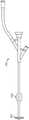
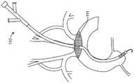
图1示出了具有安装在鞘上的闭塞元件的示例性进入鞘的侧视图。Figure 1 shows a side view of an exemplary access sheath with an occlusion element mounted on the sheath.
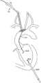
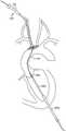
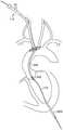
图2示出了示例性进入鞘的侧视图,该进入鞘具有安装在鞘上的过滤器元件。2 shows a side view of an exemplary access sheath with a filter element mounted on the sheath.
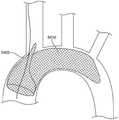
图3显示了过滤器元件的前视图。Figure 3 shows a front view of the filter element.
图4、图5A和图5B显示了进入鞘的备选实施例。Figures 4, 5A and 5B show alternate embodiments of access sheaths.
图6示意性地描绘了显示正常循环的血管系统的视图。Figure 6 schematically depicts a view of the vasculature showing normal circulation.
图7A和7B显示了部署在血管系统中的进入鞘的其他实施例。7A and 7B show other embodiments of access sheaths deployed in the vascular system.
图8A和8B显示了部署在血管系统中的进入鞘的其他实施例。8A and 8B show other embodiments of access sheaths deployed in the vascular system.
图9显示了部署在血管系统中的进入鞘的另一个实施例。Figure 9 shows another embodiment of an access sheath deployed in the vascular system.
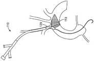
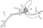
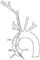
图10显示了部署在血管系统中的进入鞘的另一个实施例。Figure 10 shows another embodiment of an access sheath deployed in the vascular system.
图11显示了部署在血管系统中的进入鞘的另一个实施例,其中闭塞元件闭塞左颈总动脉。Figure 11 shows another embodiment of an access sheath deployed in the vascular system with the occluding element occluding the left common carotid artery.
图12显示了部署在血管系统中的进入鞘的另一个实施例,其中闭塞元件闭塞右颈总动脉。Figure 12 shows another embodiment of an access sheath deployed in the vascular system with the occluding element occluding the right common carotid artery.
图13显示了部署在血管系统中的进入鞘的另一个实施例,其中闭塞元件闭塞无名动脉。Figure 13 shows another embodiment of an access sheath deployed in the vascular system with the occluding element occluding the innominate artery.
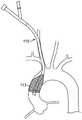
图14显示了通过进入鞘110和导丝119部署血管内假体瓣膜的输送系统。FIG. 14 shows a delivery system for deploying an endovascular prosthetic valve through an
图15A-15B示出了实施例,其中过滤器的尺寸和形状被设置为跨动脉口来部署。15A-15B illustrate an embodiment in which a filter is sized and shaped for deployment across an arterial ostium.
图15C显示了一个备选实施例,其中过滤器的尺寸和形状设置为在动脉口的远侧部署在动脉中。Figure 15C shows an alternative embodiment in which the filter is sized and shaped for deployment in the artery distal to the ostium of the artery.
图16A、图16B和图16C显示了其中过滤器通过进入鞘输送的实施例。Figures 16A, 16B, and 16C show embodiments in which the filter is delivered through an access sheath.
图17A、图17B、图17C和图17D显示了具有过滤器的进入鞘的实施例,其中过滤器的尺寸和形状被设置为跨所有头部和颈部血管的口或跨主动脉弓部署在主动脉弓中。Figures 17A, 17B, 17C, and 17D show an embodiment of an access sheath with a filter sized and shaped for deployment in the aortic arch across the ostium of all head and neck vessels or across the aortic arch .
图18A和18B显示了具有过滤器的进入鞘的备选实施例,其中过滤器的尺寸和形状设计成以便部署在升主动脉中。Figures 18A and 18B show an alternative embodiment of an access sheath with a filter sized and shaped for deployment in the ascending aorta.
图19显示了具有闭塞元件的进入鞘的实施例,其中闭塞元件的尺寸和形状被设置为部署在升主动脉中。Figure 19 shows an embodiment of an access sheath with an occlusive element sized and shaped for deployment in the ascending aorta.
图20A和20B显示了用于输送假体瓣膜的备选实施例。Figures 20A and 20B show an alternative embodiment for delivering a prosthetic valve.
图21显示了用于输送假体瓣膜的另一个实施例。Figure 21 shows another embodiment for delivering a prosthetic valve.
图22显示了经颈动脉假体主动脉瓣膜和输送系统的实施例。Figure 22 shows an embodiment of a transcarotid prosthetic aortic valve and delivery system.
图23显示了经颈动脉假体主动脉瓣膜和输送系统的备选实施例。Figure 23 shows an alternate embodiment of a transcarotid prosthetic aortic valve and delivery system.
图24显示了经颈动脉假体主动脉瓣膜和具有过滤器元件的输送系统的实施例。Figure 24 shows an embodiment of a transcarotid prosthetic aortic valve and a delivery system with a filter element.
图25显示了经颈动脉假体主动脉瓣膜和具有闭塞元件的输送系统的实施例。Figure 25 shows an embodiment of a transcarotid prosthetic aortic valve and delivery system with an occluding element.
图26A-图26G示出了过滤器构造的备选实施例。26A-26G illustrate alternative embodiments of filter configurations.
图27A和图27B示出了过滤器构造的备选实施例。27A and 27B illustrate alternative embodiments of filter configurations.
图28A和图28B显示了过滤器构造的备选实施例。Figures 28A and 28B show alternative embodiments of filter configurations.
图29A、图29B、图29C和图29D示出了过滤器构造的备选实施例。Figures 29A, 29B, 29C, and 29D illustrate alternative embodiments of filter configurations.
图30显示了主动脉过滤系统的实施例。Figure 30 shows an embodiment of an aortic filtration system.
图31A、31B和31C显示了主动脉过滤系统的备选实施例。Figures 31A, 31B and 31C show alternate embodiments of an aortic filtration system.
图32显示了进入鞘的备选实施例。Figure 32 shows an alternate embodiment of an access sheath.
图33显示了具有过滤器的进入鞘的另一个备选实施例。Figure 33 shows another alternative embodiment of an access sheath with a filter.
图34A和图34B显示了主动脉过滤器的实施例。Figures 34A and 34B show an embodiment of an aortic filter.
图35A和图35B显示了主动脉过滤器和支撑丝系统的实施例。35A and 35B show an embodiment of an aortic filter and support wire system.
图36显示了主动脉过滤器和支撑丝的备选实施例。Figure 36 shows an alternate embodiment of an aortic filter and support wire.
图37A和图37B示出了具有过滤器的进入鞘的备选实施例。37A and 37B illustrate an alternate embodiment of an access sheath with a filter.
图38显示了具有过滤器的进入鞘的备选实施例。Figure 38 shows an alternate embodiment of an access sheath with a filter.
图39显示了具有多个过滤器的进入鞘的实施例。Figure 39 shows an embodiment of an access sheath with multiple filters.
图40显示了具有多个过滤器的进入鞘的实施例。Figure 40 shows an embodiment of an access sheath with multiple filters.
图41显示了具有多个过滤器的进入鞘的备选实施例。Figure 41 shows an alternate embodiment of an access sheath with multiple filters.
图42显示了进入鞘和过滤器的备选实施例。Figure 42 shows an alternate embodiment of an access sheath and filter.
图43显示了进入鞘和过滤器的另一个备选实施例。Figure 43 shows another alternative embodiment of an access sheath and filter.
图44显示了进入鞘和过滤器的备选实施例。Figure 44 shows an alternate embodiment of an access sheath and filter.
图45A和图45B显示了进入鞘和过滤器的备选实施例。Figures 45A and 45B show alternate embodiments of access sheaths and filters.
图46显示了进入鞘和过滤器的备选实施例。Figure 46 shows an alternate embodiment of an access sheath and filter.
图47显示了进入鞘和过滤器的备选实施例。Figure 47 shows an alternate embodiment of an access sheath and filter.
图48显示了进入鞘和主动脉过滤器的备选实施例。Figure 48 shows an alternate embodiment of an access sheath and aortic filter.
图49显示了进入鞘、主动脉过滤器和导丝组件的备选实施例。Figure 49 shows an alternate embodiment of an access sheath, aortic filter and guidewire assembly.
图50A、图50B和图50C示出了主动脉过滤器的一个实施例,该主动脉过滤器通过导丝缩回到进入鞘中。Figures 50A, 50B, and 50C illustrate one embodiment of an aortic filter retracted into an access sheath over a guidewire.
图51A、图51B和图51C显示了具有支撑丝的主动脉过滤器的备选实施例。Figures 51A, 51B, and 51C show an alternate embodiment of an aortic filter with support wires.
图52-图58显示了备选实施例。Figures 52-58 show alternative embodiments.
具体实施方式Detailed ways
本文公开的是允许对天然主动脉瓣膜的动脉进入一例如经由(左或右)颈总动脉的经颈动脉进入或经由锁骨下动脉的锁骨下进入一以及将假体主动脉瓣膜植入心脏或主动脉的装置和方法。该装置和方法还提供了在这种血管内主动脉瓣膜植入手术期间用于栓塞保护的手段。Disclosed herein are arterial access to a native aortic valve—eg, transcarotid access via the (left or right) common carotid artery or subclavian access via the subclavian artery—and implantation of a prosthetic aortic valve into the heart or Aortic devices and methods. The device and method also provide a means for embolic protection during such endovascular aortic valve implantation procedures.
在一个实施例中,经颈动脉或锁骨下进入主动脉瓣膜是通过经皮穿刺或直接切入动脉来实现的。由于颈总动脉中较大动脉切开术的经皮血管闭合困难,切开可能是有利的。如果需要,可以在动脉切开术部位放置预缝线,以促进手术结束时的闭合。提供具有相关扩张器和导丝的进入鞘,其尺寸设置成配合在颈总动脉或锁骨下动脉中。进入鞘在下方朝向主动脉弓插入动脉。基于包括例如近侧动脉和/或主动脉的疾病状态以及颈动脉或无名动脉的进入角度的因素,可以选择左或右颈总动脉或锁骨下动脉作为进入主动脉的进入部位。然后可以在进入部位的远侧阻塞颈动脉。如果通过直接手术切开和动脉切开术进入,则可以通过血管夹、血管环或Rummel止血带来完成闭塞。备选地,进入鞘本身可以包括适于闭塞动脉的闭塞元件,例如闭塞球囊,以防止手术期间栓塞颗粒在进入部位远侧进入颈动脉。In one embodiment, transcarotid or subclavian access to the aortic valve is accomplished by percutaneous puncture or direct incision into the artery. Owing to the difficulty of percutaneous vessel closure with greater arteriotomy in the common carotid artery, an incision may be advantageous. If desired, pre-sutures can be placed at the arteriotomy site to facilitate closure at the end of the procedure. An access sheath is provided with an associated dilator and guidewire sized to fit in the common carotid or subclavian artery. The access sheath is inserted into the artery inferiorly towards the aortic arch. Based on factors including, for example, the disease state of the proximal arteries and/or aorta and the angle of entry of the carotid or innominate arteries, the left or right common carotid or subclavian arteries can be selected as the entry site for the aorta. The carotid artery can then be blocked distal to the entry site. If accessed by direct surgical incision and arteriotomy, occlusion can be accomplished with vascular clips, vascular rings, or Rummel tourniquets. Alternatively, the access sheath itself may include an occluding element adapted to occlude the artery, such as an occlusion balloon, to prevent embolic particles from entering the carotid artery distal to the access site during surgery.
图1示出了由具有内管腔的细长体形成的示例性动脉进入鞘110(或动脉鞘110)的侧视图。在一个实施例中,该鞘具有10-60cm的工作长度,其中工作长度是在使用期间可插入动脉中的鞘部分。鞘的管腔具有足够大的内径以适应血管内瓣膜输送系统的插入,例如18French至22French(0.236″至0.288″)系统。在一个实施例中,输送系统具有低至约0.182″的内径。进入鞘110可以具有定位在进入鞘上的可扩张闭塞元件129。闭塞元件129被构造为扩张到用于闭塞通过动脉的流的尺寸。闭塞元件129可以放置在动脉或主动脉中的任何地方。在一个实施例中,闭塞元件是闭塞球囊。1 shows a side view of an exemplary arterial access sheath 110 (or arterial sheath 110) formed from an elongated body with an inner lumen. In one embodiment, the sheath has a working length of 10-60 cm, wherein the working length is the portion of the sheath that can be inserted into the artery during use. The lumen of the sheath has an inner diameter large enough to accommodate insertion of an intravascular valve delivery system, such as an 18 French to 22 French (0.236" to 0.288") system. In one embodiment, the delivery system has an inner diameter as low as about 0.182". The
一旦鞘110定位在动脉中,闭塞元件129就在动脉内扩张以闭塞动脉,并可能将鞘固定就位。动脉进入鞘110可以包括用于输送对比剂或盐水冲洗、用于抽吸的Y形臂,和/或可以流体连接到分流器,其中分流器为血液从动脉进入鞘110流动到返回部位(例如静脉返回部位或收集容器)提供分流管腔或路径。在这点上,可以在动脉的至少一部分中建立逆行或反向血流状态。鞘110还可以包括用于通过膨胀管腔使闭塞球囊膨胀的Y形臂以及用于将血管内瓣膜输送系统引入鞘中的止血阀。备选地,如果闭塞元件是机械闭塞结构,则鞘110可以包括致动元件。血管内瓣膜输送系统可以包括假体瓣膜和输送导管。在一个实施例中,输送导管具有30、40、60、70或80cm的工作长度。Once the
在一个实施例中,抽吸可以通过进入鞘110施加到动脉。在这方面,进入鞘110可以通过Y形臂112连接到抽吸源,从而可以捕获栓塞碎片,这否则可能会进入其余的头部和颈部血管或向下游移动以进入外围血管。抽吸源可以是主动的,例如心切开术抽吸源、泵或注射器。备选地,可以建立被动流动条件,例如,通过将Y形臂112流体连接到分流器,该分流器又连接到低压源,例如处于大气压或负压的收集容器,或患者的静脉返回部位。例如,可以通过控制分流器中的流动路径的限制来调节被动流速。In one embodiment, suction may be applied to the artery through the
在一个实施例中,进入系统可以配备有一个或多个栓塞保护元件,以提供对一个或两个颈动脉的栓塞保护。例如,进入系统中可包括过滤器,以提供对一个或两个颈动脉的栓塞保护。在该实施例的一个变型中,过滤器通过对侧颈动脉、肱动脉或锁骨下动脉来部署,并在主动脉弓中跨过口而定位。如果鞘进入部位是左颈总动脉,则过滤器可以定位在无名(也称为头臂)动脉的口处。如果鞘进入部位是右颈总动脉,则过滤器可以跨左颈总动脉的口而定位。在该实施例的一个变型中,过滤器跨无名和左颈总动脉两者而部署,或跨所有三个头和颈血管(无名动脉、左颈总动脉和左锁骨下动脉)部署。过滤器元件可以内置到进入鞘110中。在一个实施例中,过滤器元件可以是与进入鞘110兼容的单独元件。例如,过滤器元件可以是可滑动地连接到进入鞘的同轴元件,或与进入鞘并排放置的元件。过滤器元件可以包括可扩张框架,从而它可以以塌陷状态插入动脉中,但随后在目标部位扩张以将过滤器元件跨一个或多个动脉的开口而定位。In one embodiment, the access system may be equipped with one or more embolic protection elements to provide embolic protection of one or both carotid arteries. For example, a filter may be included in the access system to provide embolic protection of one or both carotid arteries. In a variation of this embodiment, the filter is deployed through the contralateral carotid, brachial, or subclavian artery and positioned across the ostium in the aortic arch. If the sheath entry site is the left common carotid artery, the filter can be positioned at the ostium of the innominate (also called brachiocephalic) artery. If the sheath entry site is the right common carotid artery, the filter can be positioned across the ostium of the left common carotid artery. In a variation of this embodiment, the filter is deployed across both the innominate and left common carotid arteries, or across all three head and carotid vessels (innominate, left common carotid, and left subclavian). A filter element may be built into the
图2示出了示例性进入鞘110的侧视图,该进入鞘110具有安装在鞘上的过滤器元件111。图3示出了过滤器元件111的前视图,其示出了过滤器元件111的示例性轮廓。在图3的实施例中,过滤器元件111的尺寸和形状被设计成装配在头部和颈部血管内,并阻塞头部和颈部血管。在一个实施例中,部署的过滤器具有约2、3、4或5cm的长尺寸和约1、1.5或2cm的短尺寸。图3中所示的轮廓是示例,并且应该理解过滤器元件111的形状可以有所不同。例如,过滤器元件的形状可以是卵形、圆形、椭圆形或矩形。过滤器材料可以是编织或针织纺织材料,或者可以是多孔聚合物膜,例如聚氨酯。过滤器孔隙可以是40、100、150、200或300微米,或介于其之间的任何孔隙。过滤器元件的可扩张框架可以由弹簧材料制成,例如不锈钢或镍钛诺丝或带。FIG. 2 shows a side view of an
在具有过滤器元件的实施例中,闭塞和/或抽吸装置仍然可以是系统的一部分,以在瓣膜植入之前的过滤器部署和瓣膜植入之后的过滤器收回期间提供栓塞保护。过滤器元件本身可能是植入手术期间栓塞保护的主要方法。如图4中所示,鞘110还可以配备有闭塞元件129和过滤器元件111。In embodiments with filter elements, the occlusion and/or suction device may still be part of the system to provide embolic protection during filter deployment prior to valve implantation and filter retraction after valve implantation. The filter element itself may be the primary method of embolic protection during implantation procedures. As shown in FIG. 4 , the
在图5A所示的该实施例的另一个变型中,鞘110包括主动脉过滤器元件113,其尺寸和形状被设置为跨升主动脉部署,从而保护所有头部和颈部血管免受栓塞碎片的影响。过滤器元件的形状可以有所不同。在一个实施例中,过滤器元件的形状可以是圆锥或端部封闭的管。过滤器框架的可扩张框架的尺寸和形状设置为在部署时穿过主动脉的整个直径。例如,可扩张框架可以是直径可以从12mm扩展至30mm的环。备选地,可扩张框架可以是在一端或两端连接的一系列支柱,它们向外扩张,以跨过主动脉的直径部署过滤器元件。过滤器材料可以是编织或针织纺织材料,或者可以是多孔聚合物膜,例如聚氨酯。过滤器孔隙可以是大约40、100、150、200或300微米,或介于其之间的任何孔隙。In another variation of this embodiment shown in Figure 5A, the
过滤器元件的可扩张框架可以由弹簧材料制成,例如不锈钢或镍钛诺丝或带。与之前的变型一样,闭塞和抽吸装置可以包括在该变型中,以在过滤器部署和过滤器收回期间提供保护。主动脉过滤器元件113可以与鞘成一体,或者是与鞘兼容的单独装置,例如可以与进入鞘同轴或并排。如图5B中所示,鞘110的实施例可以包括主动脉过滤器元件113和闭塞元件129两者。The expandable frame of the filter element may be made of spring material such as stainless steel or Nitinol wire or tape. As with previous variations, occlusion and suction devices may be included in this variation to provide protection during filter deployment and filter retraction. The
图6示意性地描绘了显示正常顺行循环的血管系统的视图。血管在图6中标记如下:ACA:大脑前动脉;MCA:大脑中动脉;PCA:大脑后动脉;ICA:颈内动脉;ECA:颈外动脉;LCCA:左颈总动脉;RCCA:右颈总动脉;LSCA:左锁骨下动脉;RSCA:右锁骨下动脉;IA:无名动脉;AAo:升主动脉;DAo:降主动脉;AV:主动脉瓣膜。Figure 6 schematically depicts a view of the vasculature showing normal antegrade circulation. Vessels are labeled in Figure 6 as follows: ACA: anterior cerebral artery; MCA: middle cerebral artery; PCA: posterior cerebral artery; ICA: internal carotid artery; ECA: external carotid artery; LCCA: left common carotid artery; RCCA: right common carotid artery Arteries; LSCA: left subclavian artery; RSCA: right subclavian artery; IA: innominate artery; AAo: ascending aorta; DAo: descending aorta; AV: aortic valve.
在某些情况下,可能需要提供一种机构,用于将进入鞘110的入口点上游的颈动脉灌注到颈动脉或无名动脉中。如果进入鞘110的大小与颈动脉或无名动脉相似,则当鞘插入动脉中时,通过动脉的流可能基本上被进入鞘阻塞。在这种情况下,由于鞘对颈动脉的阻塞,上游脑血管可能无法充分灌注。在进入鞘110的一个实施例中,鞘包括用来灌注上游颈动脉和脑血管的机构。In some cases, it may be desirable to provide a mechanism for perfusing the carotid artery upstream of the entry point into the
图7A显示了部署在血管系统中的这种进入鞘110的示例性实施例。进入鞘的近侧部分具有两个平行的内管腔,它们是进入鞘的单个整体结构的一部分。第一管腔775从鞘的近端延伸到鞘的远侧末端并且在近端流体连接到分流器Y形臂755和位于鞘近端的止血阀777。第一管腔775的尺寸和形状设计成接收并能够通过止血阀777输送经导管主动脉瓣膜和输送系统。例如,第一管腔具有使得其远侧开口位于心脏或主动脉处的长度。第二管腔769定位在第一管腔附近并且从鞘的近端延伸到位于轴中部765位置处的远侧开口,并且在近端流体连接到第二灌注Y形臂767。在位置765处的第二管腔远端上存在开口。第二管腔769的尺寸和形状设计成能够将血液分流到进入鞘插入部位远侧的颈动脉。不透射线的轴标记可以在该位置处定位在鞘上,以便于在荧光镜检查下向使用者显示该开口。灌注管腔具有这样的长度,使得灌注管腔的远侧开口在使用时可以定位在远侧颈动脉中并灌注该远侧颈动脉。第一管腔的近端具有带有止血阀777和Y形臂的近侧连接器。如所提到的,止血瓣的尺寸被设计成通过其配合动脉瓣输送系统。灌注管腔的近端还具有近侧连接器。该近侧连接器和/或Y形臂允许附连分流器。FIG. 7A shows an exemplary embodiment of such an
Y形臂755可移除地连接到分流器760,分流器760又可移除地连接到第二Y形臂767。分流器限定将第一管腔775流体连接到第二管腔769的内部分流管腔。旋塞阀779可以定位在Y形臂755和分流器760之间,以允许在连接分流器760时进行冲洗和对比注射。当鞘位于动脉中时,动脉压力驱动血液流入动脉进入鞘的第一管腔775的远端,从Y形臂755流出第一管腔,然后进入分流器760,然后经由Y形臂767回到鞘中。然后血液流入平行管腔769,并在位置765处流入远侧颈动脉,以灌注动脉鞘110远侧的血管系统。分流器760中可包括直通式过滤器元件762,从而在手术期间产生的栓子不会被灌注到脑动脉中。在鞘110、分流器760和管腔769产生限制充分灌注的流动限制的情况下,分流器760可以结合有源泵770以驱动血流并提供所需水平的脑灌注。当瓣膜通过进入鞘110的第一管腔775输送时,这可能尤其如此。Y-
图7B示出了图7A的实施例的变型。Y形臂767将分流器760流体地连接到平行管腔769,当位于动脉中时,该平行管腔在位置765处将血液从分流器760重新引入动脉中。该实施例中的分流器760不与鞘中的第一管腔775流体连接。分流器760而不是通过Y形臂755从进入鞘接收血液,可以通过第二鞘连接到另一个动脉血源,例如股骨或锁骨下动脉或对侧颈动脉。在该变型中,分流的血流不受瓣膜通过进入鞘的第一管腔775的输送的限制。在该实施例中,分流管线中不需要过滤器762,因为血源远离治疗区域,并且被分流的血液中远侧栓子的风险最小。Y形臂755仍可用于冲洗和将对比剂注入鞘。在图8A中所示的另一个变型中,动脉进入鞘110具有单个管腔775,该管腔在近侧区域与Y形臂755流体连接。管腔775的尺寸和形状设计成通过止血阀777接收和实现经导管主动脉瓣膜和输送系统的输送。Y形臂755连接到分流器760,分流器又连接到第二动脉鞘802,第二动脉鞘802的尺寸和形状被设计为在引入进入鞘110的动脉进入点的远侧被引入颈动脉。旋塞阀779可以定位在Y形臂755和分流器760之间,以在连接分流器760时允许冲洗和对比剂注射。当鞘正确定位在动脉中时,动脉压力驱动流进入鞘110的管腔775,通过Y形臂755从第一管腔流出,然后通过分流器760,通过第二导管802,并在动脉进入点上游返回到颈动脉,以灌注动脉鞘110远侧的血管系统。如上所述,过滤器元件762可以包括在分流器760中,使得在手术期间产生的栓子不会被灌注到脑动脉中。在鞘110和分流器760经历限制充分灌注的流动限制的情况下,例如当瓣膜通过进入鞘110的管腔775输送时,分流器可以结合有源泵770以驱动血流并提供所需的脑灌注水平。Figure 7B shows a variation of the embodiment of Figure 7A. The Y-
图8B示出了图8A的实施例的变型。这里,第二动脉鞘802可移除地或固定地连接到分流器或流动管线760,该分流器或流动管线760继而经由另一个鞘连接到另一个动脉源,例如股骨或锁骨下动脉或对侧颈动脉。在该变型中,分流的血流不受瓣膜通过进入鞘的管腔775的输送的限制。在该实施例中,分流管线中不需要过滤器762,因为血源远离治疗区域并且分流血液中远侧栓子的风险最小。Y形臂755仍可用于冲洗和将对比剂注入鞘。Figure 8B shows a variation of the embodiment of Figure 8A. Here, the second
在上述图7A和7B以及图8A和8B中描述的实施例中,动脉进入鞘110可以包括位于鞘远端处的闭塞元件(未示出),其构造成闭塞颈动脉并辅助防止栓子进入颈动脉。此外,在这些实施例中,分流器760和如果可适用的泵770和/或第二鞘820可以作为单独的部件提供在单个套件中,以在基于导管的主动脉瓣膜置换手术期间实现经颈动脉进入和颈动脉分流。In the embodiments described above in Figures 7A and 7B and Figures 8A and 8B, the
尽管附图显示了在颈总动脉中的鞘插入,但类似的鞘或鞘/分流系统可以设计为用于锁骨下进入。Although the figures show sheath insertion in the common carotid artery, a similar sheath or sheath/shunt system can be designed for subclavian access.
在另一个实施例中,进入鞘110可以具有位于鞘110的远端和近端之间的至少一个侧开口805,如图9中所示。扩张器可以定位在鞘110内部,以在插入鞘期间阻塞侧开口805。扩张器用于帮助将鞘插入动脉。当进入鞘110被插入动脉中并且扩张器被移除时,扩张器不再阻塞开口805,使得血液可以通过侧开口805流出进入鞘110而进入远侧颈动脉。在通过进入鞘110引入血管内瓣膜输送系统并进入动脉期间,输送系统可以限制通过鞘和动脉的流动并且可以降低脑灌注水平。然而,这一手术过程是短暂的,且在这段有限的时间期间脑灌注减少不应成为临床问题。在如图10所示的该实施例的变型中,侧开口805可以具有覆盖开口805的过滤器905。过滤器905被构造为捕获栓塞碎片,使得碎片不会向下游流向脑动脉。过滤器905的尺寸和形状可以被设计成从鞘110凸出,使得当血管内瓣膜插入鞘110中时,碎片不会被向前推出鞘的远端并进入动脉。在一个实施例中,过滤器是非常薄的穿孔薄膜或编织材料,其成分类似于栓塞远侧过滤器材料。过滤器孔隙可以是约150、200或250微米。尽管图9和图10显示了在颈总动脉中的鞘插入,但可以为锁骨下进入设计类似的鞘,其中鞘插入部位离颈动脉更远,并且侧开口可以相应地进一步朝向鞘的尖端放置。In another embodiment, the
图7-10中所示的实施例中的鞘可以可选地包括定位元件,一旦鞘插入血管中就可以部署该定位元件。该定位元件可用于将鞘定位在血管中,使得侧开口805在血管内保持在期望位置。该定位特征可以采用可部署的突出构件的形式,例如环、编织物、臂或其他突出特征。该特征可以在鞘插入动脉期间缩回,但在插入鞘并且开口位于血管壁内之后部署。例如,还可以通过进入鞘110的Y形臂中的孔眼或其他特征来实现鞘保持,一旦正确定位,其就允许鞘固定到患者。The sheath in the embodiment shown in Figures 7-10 may optionally include a positioning element that can be deployed once the sheath is inserted into the blood vessel. The positioning element can be used to position the sheath in the blood vessel such that the
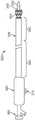
图22中示出了已被构造为通过经颈动脉进入鞘110输送的示例性瓣膜和输送系统。与经股动脉或锁骨下途径相比,从经颈动脉进入部位其的路线相当短且直。因此,输送系统可以更短,且近侧部分可以相当刚性,这两者都将允许更大的推力和扭矩控制,从而提高定位和部署假体瓣膜的准确性。远侧部分具有增大的柔性,以允许准确跟踪升主动脉周围并在主动脉环处进入位置。与当前的输送系统相比,该输送系统的材料可以包括增强的、更高硬度的和/或更厚的壁的材料,以提供这种增加的刚度。An exemplary valve and delivery system that has been configured for delivery through a
球囊可扩张假体主动脉瓣膜205安装在血管内瓣膜输送系统200的远端。输送系统具有远侧锥形末端220和在内轴210远端上的可扩张球囊215。在实施例中,该系统还具有外部套管,例如,诸如,推进套管230,其可沿装置的长轴滑动,并且其在输送期间将瓣膜保持在球囊上的位置。近侧控制组件包括用于缩回推进套管的机构,例如近侧手柄240上的滑动按钮270。在图20中,推进套管230被显示为从瓣膜和近侧球囊缩回,使得瓣膜可以在没有来自推进套管230的扰乱的情况下扩张。连接器250允许膨胀装置连接到球囊215的球囊膨胀管腔。近侧旋转止血阀260允许系统在瓣膜输送系统正在通过导丝前进并就位的时候冲洗以及围绕导丝(未示出)密封。A balloon-expandable prosthetic
瓣膜输送系统的工作长度被构造为允许瓣膜从经颈动脉进入部位输送到主动脉环。具体而言,瓣膜输送系统200的工作长度可以在45和60厘米之间。该输送系统轴也被构造为从右或左颈动脉进入部位输送。具体地,轴具有近侧坚硬部分280和更柔性的远侧部分290。在一个实施例中,远端部分的柔性是近侧坚硬部分的2至4倍。在一个实施例中,远侧柔性部分在瓣膜输送系统的总工作长度的四分之一到三分之一之间。具体而言,远侧柔性部分在10cm至20cm的范围内。在一个备选实施例中,瓣膜输送系统具有一个或多个柔性长度的过渡部分,其落在远侧柔性部分的柔性和近侧柔性部分的柔性之间。The working length of the valve delivery system is configured to allow delivery of the valve from the transcarotid access site to the aortic annulus. Specifically, the working length of the
图23中示出了构造成用于经颈动脉输送的另一个示例性瓣膜和输送系统。自扩张假体主动脉瓣膜305安装在血管内瓣膜输送系统300的远端。该输送系统具有在内轴310的远端上的远侧锥形末端320。瓣膜305位于内轴310上并包含在可沿装置的纵向轴线滑动的可伸缩套管330中。近侧控制组件包含用于缩回可缩回套管的机构,例如滑动按钮370。在一个实施例中,瓣膜305和套管330的设计使得套管可以在远侧方向上重新推进以邻接和收缩瓣膜,以便在第一位置不准确时可以重新定位瓣膜305。近侧旋转止血阀360允许系统在瓣膜输送系统在导丝上前进并进入位置时,冲洗以及围绕导丝(未示出)进行密封。Another exemplary valve and delivery system configured for transcarotid delivery is shown in FIG. 23 . A self-expanding prosthetic
与之前的实施例一样,瓣膜输送系统的工作长度被构造为允许瓣膜从经颈动脉进入部位输送到主动脉环。具体而言,瓣膜输送系统300的工作长度在45到60cm之间。输送系统轴也被构造为从右或左颈动脉进入部位输送。具体地,轴具有近侧坚硬部分380和更柔性的远端部分390。在一个实施例中,远侧部分的柔性是近侧坚硬部分的2至4倍。在一个实施例中,远侧柔性部分在瓣膜输送系统的总工作长度的四分之一到三分之一之间。具体而言,远侧柔性部分在10cm至20cm的范围内。在一个备选实施例中,瓣膜输送系统具有一个或多个柔性长度的过渡部分,其落在远侧柔性部分的柔性和近侧柔性部分的柔性之间。As with the previous embodiments, the working length of the valve delivery system is configured to allow delivery of the valve from the transcarotid access site to the aortic annulus. Specifically, the working length of the
现在描述示例性使用方法。在一个实施例中,一般方法包括以下步骤:形成从患者的颈部或肩部区域进入颈总动脉的壁的穿透;通过该穿透引入进入鞘,该进入鞘的末端向下指向动脉的口;将导丝通过进入鞘插入升主动脉并穿过天然主动脉瓣膜;以及通过进入鞘引入假体瓣膜并在天然主动脉瓣膜的位置处或附近经皮地部署该假体瓣膜。在一个实施例中,动脉在鞘的末端的远侧(上游)被阻塞。Exemplary methods of use are now described. In one embodiment, the general method comprises the steps of: forming a penetration into the wall of the common carotid artery from the neck or shoulder region of the patient; introducing an access sheath through the penetration, the distal end of the access sheath pointing downwardly toward the arterial inserting a guidewire through the access sheath into the ascending aorta and through the native aortic valve; and introducing the prosthetic valve through the access sheath and percutaneously deploying the prosthetic valve at or near the location of the native aortic valve. In one embodiment, the artery is blocked distal (upstream) of the tip of the sheath.
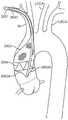
特别地,进入鞘110首先被插入血管系统中,例如通过经皮穿刺或直接手术切开和颈动脉的穿刺。如前所述,可通过LCCA实现经颈动脉进入主动脉瓣膜的途径。一旦恰当地定位,闭塞元件129就可扩张以闭塞LCCA,如图11中所示。在另一个实施例中,可以通过RCCA实现经颈动脉进入主动脉瓣膜的途径,其中闭塞元件129闭塞RCCA,如图12中所示。在另一个实施例中,可以通过RCCA实现到主动脉瓣膜的经颈动脉途径,其中闭塞元件129闭塞无名动脉IA,如图13中所示。通过闭塞元件129实现的闭塞也可以通过例如用血管夹、血管环或Rummel止血带直接夹住颈动脉血管来实现。In particular, the
一旦进入鞘被定位,栓塞保护系统或器件就可以被部署到主动脉或进入鞘的管腔的其他部位。栓塞保护器件通过闭塞、抽吸和/或过滤器元件部署,通过插入到鞘110并向下引导至升主动脉并穿过天然主动脉瓣膜的导丝119(例如0.35″或0.38″导丝)实现主动脉瓣膜的进入。在瓣膜植入前,天然主动脉瓣膜的预扩张可以使用适当大小的扩张球囊进行,例如瓣膜成形球囊。导丝119用于将球囊定位在瓣膜上并且球囊被膨胀、缩小,且然后在导丝保持就位时被移除。Once the access sheath is positioned, the embolic protection system or device can be deployed to the aorta or other location within the lumen of the access sheath. The embolic protection device is deployed by occlusion, suction and/or filter elements through a guidewire 119 (eg, 0.35" or 0.38" guidewire) inserted into the
然后在导丝119上将血管内假体瓣膜205和输送系统200插入穿过进入鞘110,并且瓣膜205定位在天然主动脉瓣膜的部位。然后植入假体瓣膜205。在植入步骤结束时,植入的假体瓣膜205的功能可以通过超声、荧光透视下的对比剂注射或其他成像手段来实现。取决于输送系统200的设计,可以根据需要调整假体瓣膜205以在最终部署之前实现最佳瓣膜功能和位置。然后从进入鞘110移除输送系统200和导丝119。在移除输送系统200和导丝119之后,移除栓塞保护元件。在此期间,可以继续抽吸以捕获被捕获在鞘末端、闭塞元件和/或过滤器元件中的任何栓塞碎片。The endovascular
然后移除进入鞘110并且关闭进入部位。如下文更详细描述的,如果该进入是手术切开直接穿刺,则血管通过打结预先放置的缝线或使用手动缝合或使用手术血管闭合装置来闭合。如果进入是经皮的,则可以采用经皮闭合方法和装置来在进入部位实现止血。在一个实施例中,在将动脉进入鞘引入穿过穿透之前,将闭合装置应用在穿透的部位处。闭合装置的类型可以有所不同。The
上述进入部位是左颈总动脉或右颈总动脉。其他进入部位也是可能的,例如左或右锁骨下动脉或左或右臂动脉。这些动脉可能需要更长和/或更曲折的通往主动脉瓣膜的路径,但与颈动脉进入相比可能提供其他优势,例如能够远离患者头部工作,能够避免不利的颈部解剖结构,例如先前的颈动脉内膜切除术或其他颈部手术或放射,或进入部位并发症情况风险较小。此外,颈动脉疾病或小颈动脉可能会妨碍颈总动脉进入。在这些进入部位中的任何一个的情况下,在TAVI期间阻塞、抽吸和/或过滤头部和颈部血管可能会提高手术的速度和准确性,并降低栓塞并发症的发生率。The aforementioned entry site is the left common carotid artery or the right common carotid artery. Other entry sites are also possible, such as the left or right subclavian artery or the left or right brachial artery. These arteries may require a longer and/or more tortuous path to the aortic valve, but may offer other advantages over carotid access, such as the ability to work away from the patient's head, the ability to avoid adverse neck anatomy, such as Prior carotid endarterectomy or other neck surgery or radiation, or access site complications are less risky. Additionally, carotid disease or small carotid arteries may obstruct access to the common carotid artery. In the case of any of these access sites, occlusion, aspiration, and/or filtering of the head and neck vessels during TAVI may improve the speed and accuracy of the procedure and reduce the incidence of embolic complications.
上文描述了各种栓塞保护系统,包括闭塞元件和过滤器。现在描述结合过滤器作为所有头部和颈部血管的栓塞保护器件的附加实施例。图15A和15B显示了实施例,其中过滤器123的尺寸和形状设置为跨过要进入的颈动脉的对侧(在相对侧)的动脉(如果要进入右颈动脉,则为左颈动脉;或如果要进入左颈动脉则为无名动脉)的口而部署。图15C显示了一个备选实施例,其中过滤器123的尺寸和形状设置为在动脉口远侧部署在动脉中。该过滤器123可以通过对侧颈动脉进入部位或通过臂或锁骨下动脉进入部位来放置。血流可通过过滤器顺行行进而进入对侧动脉,同时阻止栓塞颗粒流入头部和颈部循环。Various embolic protection systems are described above, including occlusion elements and filters. Additional embodiments incorporating filters as embolic protection devices for all head and neck vessels are now described. Figures 15A and 15B show an embodiment in which the
图16A、16B和16C示出了备选实施例,其中过滤器的尺寸和形状设置为通过进入鞘110的管腔(主管腔或单独管腔)输送。在图16A中,过滤器124的尺寸和形状设计成部署在升主动脉中。在这个实施例中,瓣膜被输送通过过滤器材料,并进入主动脉瓣膜位置。过滤器可以具有预先形成的狭缝或开口以允许瓣膜通过过滤器。预先形成的狭缝(一个或多个)可以形成在过滤器材料上,以允许瓣膜通过过滤器,同时使从狭缝产生的孔(一个或多个)的尺寸最小化。例如,用于创建单向瓣膜的狭缝(一个或多个)图案一其中瓣膜系统可以朝向心脏通过,但狭缝(一个或多个)将被流出心脏的血液关闭。备选地,该材料可以被穿刺,例如通过引入器针头,其然后可以将导丝传送通过过滤器材料并越过天然瓣膜。然后瓣膜输送系统在导丝上通过过滤器材料前进到目标部位。FIGS. 16A , 16B and 16C illustrate an alternative embodiment in which the filter is sized and shaped for delivery through the lumen (main or separate lumen) of the
在图16B中,过滤器124的尺寸和形状设置为以便在主动脉弓中输送,从而使其接触弓的壁。在图16C中,过滤器124的尺寸和形状设置为以便同时通过头部和颈部血管的开口输送。在该实施例中,过滤器可以通过侧端口离开进入鞘,以帮助将过滤器定位在主动脉弓的上面观。在图16B和16C所示的实施例中,过滤器124位于鞘开口的下游,并且瓣膜不必穿过过滤器来被输送。图16B和16C中的实施例可以通过主鞘管腔输送,并且通过离开心脏的脉动血流的帮助定位在主动脉中。当图16B和16C中的过滤器被输送出鞘并进入主动脉时,血流拖动或拉动过滤器材料并自然地帮助将过滤器定位在鞘的远侧。这些装置一直停留在该位置,直到在手术结束时通过鞘移回。In Figure 16B, the
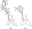
在图17A、17B、17C和17D所示的另一个实施例中,栓塞过滤器构建到或构建在进入鞘110上,并部署在主动脉弓中。在图17A和17B中,过滤器111的尺寸和形状设计成跨过主动脉弓的上面观部署,覆盖一些或所有头部和颈部血管的口。在该实施例中,由于进入部位颈动脉和对侧颈动脉两者都受到过滤器111的保护,因此在瓣膜植入手术期间不需要闭塞球囊来对鞘进行栓塞保护。然而,由于在过滤器的部署和收回期间可能存在栓塞碎片的风险,因此可能希望在瓣膜植入之前部署过滤器和在瓣膜植入之后收回过滤器期间保留闭塞球囊和抽吸功能作为栓塞保护。在图17C和17D中,主动脉过滤器113的尺寸和形状设计成在主动脉弓内跨过主动脉部署,使得所有下游血管在瓣膜植入手术期间被过滤器113保护免受栓塞碎片的影响。In another embodiment shown in Figures 17A, 17B, 17C and 17D, an embolic filter is constructed into or on an
在如图18A和18B所示的另一个实施例中,主动脉过滤器构建到或构建在进入鞘110上,并部署在升主动脉中。如图18A中所示,主动脉过滤器113在鞘的远侧部分上附接到鞘110。在使用期间,进入鞘的远侧部分位于升主动脉中,然后过滤器113跨主动脉而扩张,使得所有下游血管都受到过滤器的保护。过滤器的部署可以例如通过在鞘外侧的可缩回套管来实现,该套管在缩回时露出可扩张的过滤器。在一种构造中,过滤器部署长度可以根据可伸缩套管被拉回多少而变化。这种控制可以允许使用者根据过滤器的长度和直径将过滤器扩张为不同的尺寸。备选地,该过滤器可以由线框或结构向前推动以部署过滤器。如上所述,部署的过滤器的量可以根据患者的解剖结构通过改变要暴露的框架的多少来改变。在该实施例的如图18A所示的变型中,过滤器113相反可以是闭塞的,以在瓣膜输送期间闭塞主动脉而不是过滤血液。在该实施例的如图18B所示的变型中,过滤器113被成形为在主动脉中向远侧扩张。在这个实施例中,过滤器具有更大的表面积并且可能对流速具有更低的影响。In another embodiment, as shown in Figures 18A and 18B, an aortic filter is constructed into or on an
在图15A-18B中所示的任何场景中,闭塞球囊129可以附接到鞘110以阻塞进入的颈动脉。此外,在瓣膜被输送之后的过滤器收回步骤期间,被动或主动抽吸可通过Y形臂112施加到进入鞘,以最小化栓塞碎片行进到下游血管的风险。可选地,也可以通过鞘中的通道或通过单独的冲洗导管应用冲洗,以帮助冲洗掉松散的碎片。如上所述,在手术期间,不需要闭塞球囊129以及抽吸和/或冲洗功能,因为主动脉过滤器保护进入血管;然而,如上所述,闭塞、抽吸和/或冲洗功能可以包括在系统中以在过滤器部署和收回期间提供保护。In any of the scenarios shown in Figures 15A-18B, an
在图15A-18B所示的所有场景中,栓塞过滤器材料可以是穿孔聚合物膜、编织或针织网状材料或具有特定孔隙的其他材料。在一个实施例中,过滤器材料孔隙在80和150微米之间。在一个实施例中,过滤器材料孔隙在100和120微米之间。在一个实施例中,过滤器材料涂有肝素或其他抗凝剂,以防止手术期间血栓形成在材料上。In all of the scenarios shown in Figures 15A-18B, the embolic filter material may be a perforated polymer film, a woven or knitted mesh material, or other material with specific pores. In one embodiment, the filter material pores are between 80 and 150 microns. In one embodiment, the filter material pores are between 100 and 120 microns. In one embodiment, the filter material is coated with heparin or other anticoagulant to prevent thrombosis from forming on the material during surgery.
在另一个实施例中,如图19中所示,进入鞘110具有主动脉闭塞元件114。闭塞元件的尺寸和形状设计成闭塞升主动脉。在使用期间,进入鞘110经由右或左颈动脉引入,并且远侧部分定位在升主动脉中。预扩张球囊跨瓣膜而定位。在瓣膜预扩张之前,心脏血流会例如通过快速起搏或阿托品停止或显著减慢,闭塞元件114膨胀或扩张以闭塞升主动脉。然后执行瓣膜预扩张步骤而没有远侧栓子的风险。在闭塞元件114缩小之前,可以通过鞘110的侧臂112将抽吸施加到升主动脉。可选地,也可以应用冲洗来帮助冲洗掉松散的碎片,通过鞘中的通道或通过单独的冲洗导管。In another embodiment, as shown in FIG. 19 , the
在闭塞元件114被缩小之后,心脏血流可以恢复。接下来,定位瓣膜以进行植入。与上一步一样,心脏血流例如通过快速起搏或阿托品停止或显著减慢,闭塞元件114膨胀或扩张以闭塞扩张的主动脉。然后执行瓣膜植入步骤而没有远侧栓子的风险。在闭塞元件114缩小之前,可以通过鞘110的侧臂112将抽吸施加到升主动脉。然后闭塞元件被缩小并且在新植入的瓣膜就位的情况下恢复心脏血流。球囊材料可以被形成为产生非顺应性、顺应性或半顺应性结构。球囊可以由PET、硅树脂、弹性体、尼龙、聚乙烯或任何其他共聚物的聚合物形成。After the
在这种构造中,闭塞元件114可以是球囊,其通过用流体对比剂膨胀而扩张。在这种构造中,鞘包括可连接到膨胀装置的附加膨胀管腔。备选地,闭塞元件可以是机械地可扩张的闭塞元件,例如编织物、笼或其他可扩张机械结构,其具有在扩张时在血管中形成密封的覆盖物。In this configuration, the
在图20A和20B中所示的另一种构造中,第一进入鞘110经颈动脉部署(即,通过颈动脉,其可以包括颈内动脉、颈外动脉和/或颈总动脉)进入动脉,以提供对主动脉瓣膜的进入。第一进入鞘110如上所述构造,从而其可用于提供脑栓塞保护并将导丝119引入血管系统并穿过主动脉瓣膜。此外,第二进入鞘1805经由备选进入部位引入以从另一侧进入主动脉环,例如进入左心室的经心尖进入部位。第二进入鞘1805可用于引入输送系统400,该输送系统400被构造成用于经心尖进入以植入假体瓣膜405。在该实施例中,第二进入鞘1805可首先用于引入圈套装置1810,其被构造成握住或以其他方式套住穿过第一进入鞘110插入的导丝119的远端1815,如图20A中所示。备选地,如图20B中所示,圈套1810可以通过第一进入鞘110引入,并且导丝119通过第二进入鞘1805引入。无论导丝的哪一端被引入或圈套,圈套都可以被拉回,使得导丝的两端可以在外部固定。与其中未固定导丝远端的手术相比,导丝119的这种双端固定提供了用于放置假体瓣膜405的更中心、轴向定向和稳定的轨道。然后可以通过第二进入鞘1805将假体瓣膜405定位在导丝119上,并部署在主动脉环中。在该实施例中,第一鞘110可以小于第二进入鞘1805,因为第一鞘110不需要经导管瓣膜的通过。In another configuration shown in Figures 20A and 20B, the
在图20A和20B的实施例的变型中,经颈动脉瓣膜输送系统200和瓣膜205可以通过第一鞘110输送,如图21中所示。这种途径的优点是它需要与图20A和20B的途径相比更小的心尖穿刺。然而,在第一进入部位中需要更大的鞘。在该方法实施例中,第一进入部位在图20和21中被示为经颈动脉进入,但也可以是锁骨下或经股动脉进入部位。In a variation of the embodiment of FIGS. 20A and 20B , the transcarotid
在另一个实施例中,经颈动脉瓣膜输送系统还包括远侧栓塞保护元件。如图24中所示,瓣膜输送系统200包括可扩张过滤器元件211,其尺寸和形状设计成当瓣膜输送系统200定位成在所需位置部署瓣膜时跨过升部扩张。过滤器的部署可以通过位于鞘外侧的可伸缩套管来完成,该套管在缩回时露出可扩张过滤器。备选地,过滤器可以通过线框或结构向前推动以部署过滤器。过滤器元件可以固定到瓣膜输送系统的推进套管230上,或者它可以固定到可移动的外套管上,以便它可以相对于瓣膜独立地定位。在后一种变型中,过滤器可以在瓣膜穿过天然瓣膜位置之前定位和扩张,从而在手术的穿过步骤期间保护下游流免受远侧栓子的影响。In another embodiment, the transcarotid valve delivery system further includes a distal embolic protection element. As shown in Figure 24, the
在如图25中所示的该实施例的一个变型中,瓣膜输送系统200包括闭塞元件212,其尺寸和形状设计成当瓣膜输送系统200定位成在所需的位置部署瓣膜时,闭塞升部。闭塞元件212可以是球囊,其通过用流体对比剂膨胀而扩张。在这种构造中,瓣膜输送系统200包括可连接到膨胀装置的附加膨胀管腔。备选地,闭塞元件可以是机械可扩张闭塞元件,例如编织物、笼或其他可扩张机械结构,其具有在扩张时在血管中形成密封的覆盖物。闭塞元件可以固定到瓣膜输送系统的推进套管230上,或者它可以固定到可移动的外部套管上,从而它可以相对于瓣膜独立地定位。In one variation of this embodiment as shown in Figure 25, the
如果进入颈动脉是通过手术切开,则可以使用标准血管手术技术关闭进入部位。荷包缝合可在鞘管插入之前应用,且然后在鞘管移除后用于系住进入部位。如果进入部位是经皮进入,则可以使用多种血管闭合元件。在一个实施例中,血管闭合元件是机械元件,其包括锚定部分和闭合部分,例如自闭合部分。锚定部分可以包括钩、销、钉、夹、尖齿、缝合等,它们在穿透周围接合在颈总动脉的外表面中,以在穿透完全打开时固定自闭合元件。该自闭合元件还可以包括弹簧状或其他自闭合部分,当移除鞘时,该部分将闭合锚定部分,以便将动脉壁中的组织拉到一起以提供闭合。通常,闭合就足够了,因此不需要采取进一步措施来封闭或密封穿透。然而,可选地,可能希望在鞘被抽回之后提供对自闭合元件的补充密封。例如,自闭合元件和/或元件区域中的组织道可以用止血材料处理,例如生物可吸收聚合物、胶原蛋白塞、胶水、密封剂、凝血因子或其他凝血促进剂。备选地,组织或自闭合元件可以使用其他密封协议来密封,例如电灼、缝合、夹闭、钉合等。在另一种方法中,自封闭元件将是自密封膜或垫圈材料,其通过夹、胶水、带或其他方式附接到血管的外壁。自密封膜可具有内部开口,例如狭缝或横切,其通常会针对血压关闭。这些自闭合元件中的任何一个都可以设计为放置在开放式外科手术中或被经皮地部署。If the access carotid artery is through a surgical incision, the access site can be closed using standard vascular surgical techniques. A purse-string suture can be applied prior to sheath insertion, and then used to tie down the access site after sheath removal. If the access site is percutaneous, a variety of vessel closure elements can be used. In one embodiment, the vessel closing element is a mechanical element that includes an anchoring portion and a closing portion, eg, a self-closing portion. The anchoring portion may include hooks, pins, pins, clips, tines, sutures, etc., which engage in the outer surface of the common carotid artery around the penetration to secure the self-closing element when the penetration is fully open. The self-closing element may also include a spring-like or other self-closing portion that, when the sheath is removed, will close the anchoring portion so as to draw tissue in the arterial wall together to provide closure. Often, closure is sufficient, so no further steps are required to close or seal the penetration. Optionally, however, it may be desirable to provide a supplemental seal to the self-closing element after the sheath has been withdrawn. For example, the self-closing element and/or the tissue tract in the region of the element can be treated with a hemostatic material, such as a bioabsorbable polymer, collagen plug, glue, sealant, coagulation factor, or other coagulation enhancer. Alternatively, the tissue or self-closing element may be sealed using other sealing protocols, such as electrocautery, suturing, clipping, stapling, and the like. In another approach, the self-sealing element would be a self-sealing membrane or gasket material that is attached to the outer wall of the vessel by clips, glue, tape, or other means. Self-sealing membranes can have internal openings, such as slits or cross-cuts, which would normally be closed for blood pressure. Any of these self-closing elements can be designed to be placed in open surgery or deployed percutaneously.
在备选实施例中,血管闭合元件是基于缝合的血管闭合装置。基于缝合的血管闭合装置可以在血管进入部位上设置一个或多个缝合部,使得当在鞘移除后缝合端系紧时,一个或多个缝线为进入部位提供止血。缝合可以在通过动脉切开术插入手术鞘之前或在从动脉切开术移除鞘之后应用。该装置可以在设置缝合之后但在放置手术鞘之前和期间保持动脉切开术的临时止血,并且还可以在手术鞘退出之后但在系紧缝合部之前保持临时止血。名称为″SYSTEMS AND METHODS FOR TREATING ACAROTID ARTERY(用于治疗颈动脉的系统和方法)″的系列号为No.12/834,869的美国专利申请,该申请通过引用以其整体并入本文中,描述了示例性闭合装置并且还描述了与本文公开的装置、系统和方法相关并且可以与本文公开的装置、系统和方法组合的各种其他装置、系统和方法。In an alternative embodiment, the vessel closure element is a suture-based vessel closure device. Suture-based vascular closure devices may provide one or more sutures on the vascular access site such that when the suture ends are tied after sheath removal, the one or more sutures provide hemostasis to the access site. Sutures may be applied prior to insertion of the surgical sheath through the arteriotomy or after removal of the sheath from the arteriotomy. The device can maintain temporary hemostasis of the arteriotomy after placement of the sutures but before and during placement of the surgical sheath, and can also maintain temporary hemostasis after the surgical sheath is withdrawn but before the sutures are tied. U.S. Patent Application Serial No. 12/834,869, entitled "SYSTEMS AND METHODS FOR TREATING ACAROTID ARTERY," which is hereby incorporated by reference in its entirety, describes Exemplary closure devices and also describe various other devices, systems and methods related to and in combination with the devices, systems and methods disclosed herein.
在图26A-26E中所示的另一个实施例中,主动脉过滤器2603被构造为圆锥形或类似于具有可扩张远侧带2604的圆锥形,其附接至主动脉过滤器2603,使得远侧带2604至少部分地围绕主动脉过滤器2603延伸或位于其内。如图26A-26E中所示,主动脉过滤器2603具有连接到内部输送导管(IDC)2600的近端,该内部输送导管(IDC)2600具有位于病人的身体外部的近端。IDC2600是一种细长体,其可具有一个或多个内管腔,例如双内管腔。IDC2600可以被外鞘2601a、b(在图26A中显示为横截面)围绕。外部鞘2601可以对应于本文所述的动脉鞘110。一根或多根拉丝2602a和2602b(在图26B的局部视图中示出)连接到主动脉过滤器2603。拉丝2602a和2602b的远侧部分连接到主动脉过滤器2603的远侧部分。拉丝2602a和2602b也位于IDC2600的远侧区域内,例如在双管腔内。In another embodiment shown in Figures 26A-26E, the
如图26C中所示,IDC2600的外管腔可以具有单个圆形孔口2605a,拉丝2602a和2602B都可以定位在该孔中。备选地,如图26D中所示,IDC2600的外管腔可具有两个细长孔口2605b和2605c,或如图26E中所示,两个圆形孔口2605d和2605e,使得拉丝2602a和2602b中的每一个被定位在单独的孔口中。As shown in Figure 26C, the outer lumen of the
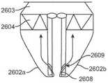
如图26F和26G中所示,可以使用IDC2600的管腔内的拉丝2602a、b的不同构造。IDC2600可以包括一个或两个靠近最远侧开口2606的远侧开口。如图26F中所示,IDC2600可以包括与外管腔连通的远侧开口2607,从而拉丝2602a、b可以连接到主动脉过滤器2603的远端,并延伸回到IDC2600的最远侧开口2606和内管腔中,并通过远侧开口2607而穿过外管腔并离开IDC2600。备选地,如图26G中所示,IDC2600可以包括形成横向通道的外管腔中的第一远侧开口2608和第二远侧开口2609,使得拉丝2602a、b可以连接到主动脉过滤器2603的远端并向后延伸进入IDC2600的第一远侧开口2608,通过横向通道,并从第二远侧开口2609出来以离开IDC2600。As shown in Figures 26F and 26G, different configurations of the
主动脉过滤器2603可以使用外鞘2601a、b和/或拉丝2602a、b来折叠。拉丝2602a、b可以连接到主动脉过滤器2603的远端并在IDC2600的远端内向下延伸回来。可以使用具有用于拉丝2602a、b的单独管腔2605a-e的双管腔IDC2600。拉丝2602a、b的使用或主动脉过滤器2603的远端与IDC2600的连接允许主动脉过滤器2603在IDC2600周围折叠以便移除。当外鞘2601a、b在主动脉过滤器2603的外表面上移动并在IDC2600内旋转时,通过由外鞘2601a、b的摩擦引起的缠绕运动发生折叠。外鞘2601a、b可以在IDC2600保持就位时放置在主动脉过滤器2603上。
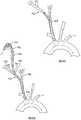
现在参考图27A-27C,在该实施例的变型中,主动脉过滤器2703被构造为具有扩张或可扩张远侧带2704的圆锥,其附接到主动脉过滤器2703,使得远侧带2704在主动脉过滤器2703周围延伸或定位在主动脉过滤器2703内。主动脉过滤器2703具有连接到内部输送导管(IDC)2600的近端。IDC2600可以被外鞘2601包围(以附图标记2601a,2601b在横截面中示出)。主动脉过滤器2703被构造成靠近主动脉瓣膜延伸,且因此具有更大的过滤面积,如图27A中所示。为了折叠主动脉过滤器2703,可以使用连接到主动脉过滤器2703远端的拉丝2602a、b(图27B)(如图27B所示),或者可以将主动脉过滤器2703的远端连接到IDC2600。拉丝2602a、b或主动脉过滤器2703与IDC2600的连接可用于围绕IDC2600折叠主动脉过滤器2703,以便当其在主动脉过滤器2703的外表面上移动并且围绕IDC2600旋转以产生包裹运动并促进折叠和移除时,移除使用外鞘2601的摩擦力。拉丝闭合构造或直接连接闭合构造2701b可用于折叠和移除主动脉过滤器。Referring now to Figures 27A-27C, in a variation of this embodiment, the
在另一个实施例中,如图28A-28C中所示,主动脉过滤器2803被构造为具有扩张或可扩张远侧带2804的圆锥,其附接到主动脉过滤器2803使得远侧带2804围绕主动脉过滤器2803延伸、或位于主动脉过滤器2803内。主动脉过滤器2803具有通过搭接接头2805连接到内部输送导管(IDC)2600的近端。IDC2600可以被外鞘2601包围。如图28A和28B中所示,主动脉过滤器2803的近端连接到外鞘2601,且主动脉过滤器2803的远端连接到IDC2600的远端。这种构造允许主动脉过滤器2803被拉闭合,或另外通过在保持IDC2600静止的同时向近侧移动外鞘2601而折叠到更小的尺寸。这允许主动脉过滤器2803通过在外鞘2601和IDC2600之间的直接旋转来包裹,并且不需要将鞘2601放置在主动脉过滤器2803上。In another embodiment, as shown in Figures 28A-28C, the
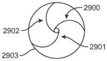
在如图29A中所示的该实施例的变型中,主动脉过滤器2903被构造为具有扩张或可扩张远侧带2904的圆锥,其附接到主动脉过滤器2903使得远侧带2904围绕主动脉过滤器2903延伸、或位于主动脉过滤器2903内。主动脉过滤器2903具有连接到内部输送导管(IDC)2600的近端。IDC2600可以被外鞘2601包围。如图29B-29D所示,其以横截面显示了主动脉过滤器2903,IDC2600的远端或远侧区域可以包括径向支柱2900、2901和2902,其连接到主动脉过滤器2903的远侧区域并联接到中心IDC2600。支柱2900、2901和2902可以被拉紧或缠绕,以闭合或折叠主动脉过滤器2903。另外或备选地,支柱2900、2901和2902可以被压缩以向主动脉过滤器2903提供稳定力。支柱2900、2901和2902的形状或轮廓可以至少部分地是螺旋形,这可有助于使IDC2600在主动脉血管的中间居中,并在主动脉过滤器2903上提供向外的力,其并非在血管壁上的单个力点,并提供在凝块阻塞主动脉过滤器2903的大部分表面之前分解和/或捕获凝块的能力。In a variation of this embodiment as shown in Figure 29A, the
如上所述以及在图26A至29D中所示的实施例被图示和讨论为通过RCCA引入,然而应当理解的是,这些实施例可以被调整和/或修改,以通过LCCA引入。本文所述的任何实施例都可以通过RCCA或LCCA来传递。The embodiments described above and shown in Figures 26A to 29D are illustrated and discussed as being introduced by RCCA, however it should be understood that these embodiments may be adapted and/or modified to be introduced by LCCA. Any of the embodiments described herein may be delivered via RCCA or LCCA.
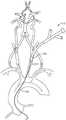
图30显示了主动脉弓和从其延伸的三个动脉的示意图:包括右锁骨下动脉(RSCA)和无名动脉(IA)的右颈总动脉(RCCA)、左颈总动脉(LCCA))以及左锁骨下动脉(LSCA)。多个主动脉过滤器3003a、3003b、3003c和3003d可以部署在这些动脉中一根或多根中,以向相应的动脉提供过滤保护。例如,过滤器3003a位于RCCA中。经导管主动脉瓣膜置换(TAVR)工具3001可以通过多种路径中的任何一种远离过滤器3003a被部署到RCCA中。过滤器3003b位于RSCA中。过滤器3003c位于LCCA中。过滤器3003d位于LSCA中。过滤器3003a-3003d可以按照首先3003a、然后是3003d、3003c和3003b的顺序部署。备选地,过滤器3003a-3003d可以按照首先3003d,然后是3003c、3003b和3003a的顺序部署。其他部署顺序也是可以的。Figure 30 shows a schematic diagram of the aortic arch and three arteries extending therefrom: right common carotid artery (RCCA), left common carotid artery (LCCA), including right subclavian artery (RSCA) and innominate artery (IA), and left clavicle inferior artery (LSCA). A plurality of
图31A-31C显示了包括头臂过滤器3100的主动脉过滤系统的实施例。头臂过滤器3100具有主体3103,主体3103具有远侧颈部区域3105、第一叉部件3104A和在过滤器的近侧区域的第二叉部件3104b。第二叉部件3104b可具有可变长度或可不存在。该头臂过滤器3100可以部署在例如右RCCA中,使得颈部区域3105接触RCCA并且主体3103不接触RCCA的整个长度。额外的过滤器3106和3107可以分别部署在LCCA和LSCA中。头臂过滤器3100的另一个实施例在图31B中示出。头臂过滤器3100的又一个实施例在图31C中示出,没有第二叉部件3104b。如图31C中所示,头臂过滤器3100允许血流沿所示箭头方向通过主体3103的壁。31A-31C show an embodiment of an aortic filtration system including a
图32显示了头臂过滤器3201的另一个实施例,其具有细长体和主动脉过滤器3203。细长体延伸穿过RCCA(并且可能阻塞RSCA)并连接到主动脉过滤器3203。主动脉过滤器3203的尺寸和形状设计成位于主动脉弓中,并保护从那里延伸出来的动脉的口。FIG. 32 shows another embodiment of a
图33显示了头臂过滤器3301的又一个实施例,该过滤器具有细长体和单独的主动脉过滤器3303。头臂过滤器的细长体3301延伸穿过RCCA并进入主动脉弓,在此它连接到主动脉过滤器3303的边缘。该主动脉过滤器的尺寸和形状设计成位于主动脉弓中,并保护从那里延伸的动脉的口。Figure 33 shows yet another embodiment of a
图34A-34C是主动脉过滤器3403的实施例的示意图。工具3001可以进入RCCA(通过多种路径中的任一种),穿过RCCA到达主动脉弓,并穿过位于主动脉弓中的主动脉过滤器3403。主动脉过滤器3403的尺寸和形状设计成位于主动脉弓中并保护从那里延伸的动脉。主动脉过滤器3403可以包括围绕主动脉过滤器3405的外径设置的远侧套管3405以及在套管3405的基部处的环3402。环3402可以是不透射线的。套管3405可以包括例如镍钛诺和/或聚氨酯。套管3405可以用作外部支撑。如图34B所示,套管3405在插入后可平滑地配合在TAVR工具3001的外径周围。34A-34C are schematic illustrations of an embodiment of an
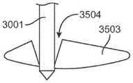
图35A-35B是附接到支撑丝3501的主动脉过滤器3503的实施例的示意图。该实施例适用于在例如经颈动脉和/或股动脉进入中使用。如图35A中所示,支撑丝3501延伸穿过RCCA并在进入位置3504的一端附接到主动脉过滤器3503。进入位置3504可以包括致密的网,其保持闭合直到通过插入TAVR工具3001而打开。图35B示出了将TAVR工具3001插入进入位置3504的网中并穿过主动脉过滤器3503。35A-35B are schematic illustrations of an embodiment of an
图36是具有支撑丝3601的主动脉过滤器3603的另一个实施例的示意图。该实施例也适用于经颈动脉和/或股动脉进入。该支撑丝延伸穿过RCCA并连接到主动脉过滤器3603和进入窗3604的一个边缘。支撑丝3601可以由多种材料中的任一种制成。非限制性示例材料包括不锈钢、镍钛诺和铝。主动脉过滤器3603的尺寸和形状设计成位于主动脉弓中并保护从那里延伸的动脉。主动脉过滤器3603包括设置在主动脉过滤器3603的直径周围的远侧环3602、以及进入窗3604。进入窗3604可以具有比主动脉过滤器3603更紧的孔隙,并且在通过进入窗3604插入TAVR工具3001时可以松开其孔隙。进入窗3604可以松开其孔隙,以允许TAVR工具3001通过主动脉过滤器3603。36 is a schematic diagram of another embodiment of an
如上所述和图32至36中所示的实施例被图示为通过RCCA引入,然而应当理解,这些实施例可以被调整和/或修改以通过LCCA或其他路径引入。The embodiments described above and shown in Figures 32-36 are illustrated as being introduced by RCCA, however it should be understood that these embodiments may be adapted and/or modified to be introduced by LCCA or other paths.
图37A-37B是具有支撑丝3701的主动脉过滤器3703的又一个实施例的示意图。如图37A中所示,支撑丝3701延伸穿过RCCA并连接到主动脉过滤器3703上的进入位置3702。主动脉过滤器3703的尺寸和形状设置为位于升主动脉中并通过主动脉弓扩张。图37B显示了主动脉过滤器3703和进入位置3702的横截面。37A-37B are schematic illustrations of yet another embodiment of an
图38是主动脉过滤系统的另一个实施例的示意图。支撑丝3801延伸穿过RCCA,并连接到主动脉过滤器3803。主动脉过滤器3803的尺寸和形状设置为位于主动脉弓中并保护LCCA和LSCA。另一个过滤器3802位于RSCA中。在本实施例中,主动脉滤器3803和滤器3802两者都不覆盖RCCA。38 is a schematic diagram of another embodiment of an aortic filtration system. The
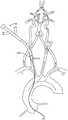
图39是主动脉过滤系统的示意图。过滤系统具有第一细长部分3902a,其尺寸和形状设计成延伸通过RCCA。第一部分3902a包括用于接收导丝3901的管腔。第一部分3902a还包括允许第一部分3902a膨胀的膨胀端口和环结构3905。环结构3905是可膨胀的并且可以围绕输送导管产生密封。在输送导管和无名动脉(IA)的内壁之间形成密封。该密封可以防止栓塞物质在输送导管周围进入RCCA。可以调节膨胀压力以允许输送导管的轴向平移,同时仍然保持密封。过滤系统具有第二部分3902b,其耦联到第一部分3902a,使得第二部分3902b的尺寸和形状设计成延伸穿过LCCA,以及延伸穿过LSCA并耦联到第二部分3902b的第三部分3902c。Figure 39 is a schematic diagram of an aortic filtration system. The filter system has a first
第一部分3902a耦联到环结构3905,该环结构3905的尺寸和形状设置为位于RCCA的口处。第一部分3902a向近侧延伸穿过RCCA并耦联到第二部分3902b。第二部分3902b包括附接到桥的过滤器3903b,并且过滤器3903b位于LCCA内部。第三部分3902c还包括过滤器3903a,其位于LSCA内部并通过第二桥连接到第二部分3902b。过滤系统的尺寸和形状设置为定位在RCCA中,过滤器3903b的尺寸和形状设计成定位在LCCA中,且过滤器3903a的尺寸和形状设计成定位在LSCA中。The
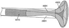
图40是主动脉过滤系统的另一个实施例的示意图。该系统包括导丝4001,导丝4001具有延伸通过RCCA并连接到臂主动脉过滤器4003a的第一部分。该系统还包括通过第一桥连接到导丝4001的过滤器4003b和通过第二桥连接到导丝4001的过滤器4003c。臂主动脉过滤器4003a的尺寸和形状设置为位于RCCA的口处。臂主动脉过滤器4003a可以被构造为具有内部可扩张过滤器的支架。过滤器4003b的尺寸和形状设计成定位在LCCA中。过滤器4003c的尺寸和形状设计成定位在LSCA中。Figure 40 is a schematic diagram of another embodiment of an aortic filtration system. The system includes a
图41是主动脉过滤系统的另一个实施例的示意图。过滤系统具有第一细长部分4102a,其尺寸和形状设计成延伸通过RCCA。第一部分4102a包括用于接收导丝4101的管腔。第一部分4102a还包括允许第一部分4102a膨胀的膨胀端口,并且还包括钩结构4105。钩结构4105是可膨胀的,并且可以在输送导管(未显示)周围形成密封。在输送导管和无名动脉(IA)的内壁之间形成密封。这种密封可以防止栓塞物质在输送导管周围进入RCCA。可以调节膨胀压力以允许输送导管轴向平移,同时仍保持密封。该过滤系统具有第二部分4102b,其耦联到第一部分4102a,使得第二部分4102b的尺寸和形状设计成延伸穿过LCCA,以及延伸穿过LSCA并耦联到第二部分4102b的第三部分4102c。Figure 41 is a schematic diagram of another embodiment of an aortic filtration system. The filter system has a first elongated portion 4102a sized and shaped to extend through the RCCA. The first portion 4102a includes a lumen for receiving the
第一部分4102a耦联到钩结构4105,其尺寸和形状设置为位于RCCA的口处。钩结构4105具有两个或多个臂,这些臂相互缠绕以形成环形。第一部分4102a向近侧延伸穿过RCCA并且耦联到第二部分4102b。第二部分4102b包括附接到桥的过滤器4103A,并且过滤器4103A位于LCCA内部。第三部分3902c也包括过滤器4103b,其位于LSCA内部并通过第二桥连接到第二部分4102b。过滤系统的尺寸和形状设置为定位在RCCA中,其中过滤器4103A的尺寸和形状设计成定位在LCCA中,且过滤器4103B的尺寸和形状设计成定位在LSCA中。The first portion 4102a is coupled to a
图42显示了栓塞保护过滤系统的示意图。该系统包括用于TAVR系统的经颈动脉输送鞘4201。输送鞘4201可选地包括靠近输送鞘4201的远侧末端的闭塞球囊4202。球囊4202和输送鞘4201的尺寸和形状被设计成定位在无名动脉(IA)内。球囊4202的膨胀防止从主动脉瓣膜或升主动脉或主动脉弓释放的栓塞物质进入颈总动脉。过滤器4203附接到输送鞘4201的远端。为了通过RCCA进入,过滤器4203跨过LCCA和LSCA的口布置。过滤器4203防止栓塞物质进入大脑。栓塞物质通过主动脉弓分流。在输送期间,过滤器4203可以在向前位置、在输送鞘4201的本体远侧折叠。Figure 42 shows a schematic diagram of an embolic protection filtration system. The system includes a
图43显示了栓塞保护过滤系统的另一个实施例的示意图。该系统包括用于TAVR系统的经颈动脉输送鞘4301。输送鞘4301可选地包括在输送鞘4301的远侧末端附近的闭塞球囊4302。在任何实施例中,可以例如通过使用Rummel止血带从外部闭塞动脉。球囊4302和输送鞘4301A的尺寸和形状设置为定位在LCCA内。球囊4302的膨胀防止从主动脉瓣膜或升主动脉或主动脉弓释放的栓塞物质进入颈总动脉。过滤器4303a和4303b附接到输送鞘4301的远端。为了通过LCCA进入,过滤器4303a跨过无名动脉(IA)的口设置,且过滤器4303b跨过LSCA的口设置。过滤器4303a和4303b防止栓塞物质进入大脑。栓塞物质通过主动脉弓分流。在输送期间,过滤器4303a和4303b可以在向前位置、在输送鞘4301的本体远侧折叠。Figure 43 shows a schematic diagram of another embodiment of an embolic protection filtration system. The system includes a
图42和43中所示的栓塞保护过滤系统可以通过可移动的薄壁管(未示出)固定在适当的位置。因此,与将过滤器的全长折叠在输送鞘的外表面上相比,可以减小系统的整体输送轮廓。使用这些过滤系统进行栓塞保护使得可以防止栓塞物质到达大脑,因为不需要完整的过滤篮。栓塞物质通过IA和LCCA的口分流到远侧血管床,其中对患者的风险大大降低。对于某些应用,双过滤器构造可能被认为是有利的,因为解剖结构通常提供从LCCA的口到主动脉瓣膜的相对直接、笔直的路径。The embolic protection filter system shown in Figures 42 and 43 can be held in place by a removable thin walled tube (not shown). Thus, the overall delivery profile of the system can be reduced compared to folding the full length of the filter over the outer surface of the delivery sheath. Embolic protection using these filter systems makes it possible to prevent embolic material from reaching the brain, since a complete filter basket is not required. Embolic material is shunted through the ostia of the IA and LCCA to the distal vascular bed, where the risk to the patient is greatly reduced. For certain applications, a dual filter configuration may be considered advantageous because the anatomy generally provides a relatively direct, straight path from the ostium of the LCCA to the aortic valve.
图44显示了栓塞保护过滤系统的实施例的示意图。如图44中所示,瓣膜输送鞘4401被构造为在无名动脉内终止或定位在无名动脉内。可扩张过滤器4403延伸到降主动脉中,以过滤在主动脉瓣膜置换手术期间可能释放的任何颗粒物质。Rummel止血带4406或类似的止血带或夹钳装置可用于将瓣膜输送鞘4401的近侧部分固定在颈总动脉内。Rummel止血带4406还降低了未被可扩张过滤器4403捕获的栓塞物质不流入神经血管系统的可能性。可扩张过滤器4403可以由例如镍钛诺网构成。该网可以热定形以自扩张,并符合主动脉壁的内表面。该网可以用丝或支柱加强,以提供改进的向外力,并帮助将网固定在主动脉的壁上。在非限制性示例中,具有可扩张过滤器4403的瓣膜输送鞘4401可以通过右颈总动脉或左颈总动脉引入主动脉。Figure 44 shows a schematic diagram of an embodiment of an embolic protection filtration system. As shown in Figure 44, the
现在参考图45A-45B,在备选实施例中,动脉鞘110被构造为促进来自ICA和ECA的逆行流805通过动脉鞘110中的开口进入低压静脉循环。代替从主动脉到远侧CCA的分流流,鞘从远侧颈动脉抽血。来自ICA和ECA的逆行血流805通过威利斯环(Circle of Willis)和其他侧支血管从大脑的对侧夹带血液,从而向大脑的同侧提供含氧血液。该实施例不是提供导管以提供越过鞘进入远侧CCA的顺行血流,而是建立逆行血流805。如果在分叉处或在ICA中存在颈动脉疾病(这可能在顺行血流与血管操作相结合时发生栓塞),这可能是向同侧循环提供含氧血液的安全方式。Referring now to FIGS. 45A-45B, in an alternate embodiment, the
图45B显示了部署在血管系统中的动脉鞘110。动脉鞘110的近侧区域上的Y形臂755连接到分流器760,分流器760被构造为在进入颈动脉的进入点上游的位置765处将血流重新引入颈动脉。来自ICA和ECA的逆行血流由箭头表示。第二Y形臂767流体地连接到分流器760和平行管腔769,该管腔在位置765处将血液从分流器760重新引入动脉中。过滤器元件762可以包括在分流器760中,从而在手术期间产生的栓子不会被灌注到脑动脉中。Figure 45B shows the
图46显示了动脉鞘的另一个实施例。如图46的示例中所示,鞘插入左颈总动脉(LCCA)。至少一个栓塞保护元件,例如过滤器4603,朝向无名动脉的孔口延伸。过滤器4603可以是动脉鞘110的一体部分(例如附接到鞘的远侧区域),或者它可以是单独的构件,例如耦联到具有细长元件的栓塞保护系统,该细长元件可以通过动脉鞘119被输送到主动脉。过滤器4603不一定直接阻塞无名动脉,或直接过滤进入无名动脉的血液。相反,过滤器4603扰乱无名动脉的孔口附近的血流模式。该过滤器可以位于主动脉中的任何位置,例如至少部分地位于升主动脉中。Figure 46 shows another embodiment of an arterial sheath. As shown in the example of Figure 46, the sheath is inserted into the left common carotid artery (LCCA). At least one embolic protection element, such as
过滤器4603可以具有被选择以改变例如在主动脉弓处通过主动脉的血液流动的尺寸、形状、轮廓或表面轮廓。在这方面,过滤器4603可以具有外表面,该外表面可以是固体表面或扰乱通过主动脉的血流的扰乱表面(例如网)。在一个实施例中,过滤器4603可以包括如下单独的构件或耦联到该单独的构件:该构件被成形为以特定方式(例如在特定方向上)导引、引导或扰乱血流或产生流动模式。过滤器4603可以具有引导流朝向主动脉内的位置的部分,例如翅片或其他形状。诸如流引导元件4612的栓塞保护元件可以定位在过滤器4603的远侧,例如在过滤器的上游。流引导元件4612可以将血流引导向过滤器4603,过滤器4603可以相对于流引导元件4612定位在主动脉内的任何位置。流引导元件4612可以具有轮廓化表面,例如凹表面、凸表面、成角度表面(相对于流动方向)、弯曲表面或它们的组合,其被构造为将血流引导到期望的方向。过滤器4603可以定位在重定向的流动路径中,以捕获重定向血流中的碎片(如果存在的话)。流引导元件4612或第二流引导元件也可以或备选地定位在过滤器4603的下游,使得在血液流过和/或通过过滤器之后,该流引导元件进一步重定向血流远离从主动脉分支的动脉。这样,该流引导元件可以重定向任何未被过滤器捕获的碎片。流引导元件4612可以附接到过滤器,或者它可以是单独的、分离的构件。在一个实施例中,流引导元件4612也是过滤器。在另一个实施例中,该流引导元件不是过滤器。流引导元件4612可以通过鞘输送到期望的位置,或者它可以附接到鞘,例如附接到鞘的远侧区域。流引导元件4612也可以或可备选地与本文所述的任何栓塞保护装置结合使用。例如,流引导元件可以与篮或蝶网结合使用,例如图44中所示的过滤器4403,其中流引导元件位于捕获元件例如过滤器4403的上游或下游。The
过滤器可以定位成延伸到主动脉的管腔中,或者它可以定位成至少部分地与主动脉的壁齐平。在一个实施例中,当血液流过并接触过滤器和/或流引导元件时,过滤器或流引导元件与血流相互作用以实现期望的血流分布。例如,这些构件可以使血液从层流例如在主动脉的壁处或附近转变为湍流。被扰乱的血流可能使得任何栓塞物质从由主动脉分支出来的动脉的孔口流出。一个或多个捕获过滤器(例如本文描述的任何过滤器)可以定位在主动脉中以捕获这种重定向的血流,使得第一过滤器或其他元件以将被扰乱的血液引导至一个或多个过滤器以捕获血流中的任何物质的方式来扰乱血流。The filter can be positioned to extend into the lumen of the aorta, or it can be positioned to be at least partially flush with the wall of the aorta. In one embodiment, as blood flows through and contacts the filter and/or flow directing element, the filter or flow directing element interacts with the blood flow to achieve the desired blood flow distribution. For example, these members may convert blood from laminar flow to turbulent flow, eg, at or near the wall of the aorta. The disrupted blood flow may allow any embolic material to flow out of the orifice of the artery branching off from the aorta. One or more capture filters, such as any of the filters described herein, can be positioned in the aorta to capture this redirected blood flow such that a first filter or other element is used to direct disturbed blood to one or more of the Multiple filters disrupt the blood flow in a way that captures anything in the bloodstream.
过滤器4603的存在可导致流动改变,例如从层流转变为湍流。被扰乱的流体流动模式引导源自主动脉瓣膜的栓塞物质4610远离无名动脉的孔口。如图47中所示,该装置可以备选地构造成通过RCCA引入。过滤器4603也可以与流引导元件结合使用,例如关于图47描述的流引导元件4612。该流引导元件也可以与任何类型的栓塞捕获装置一起使用,该装置捕获主动脉中的全部或部分栓塞碎片,其中流引导元件位于这种栓塞捕获装置的上游和/或下游。The presence of
现在参考图47,可以将鞘插入右CCA。过滤器4703延伸到主动脉弓中。过滤器4703引导栓塞物质4710扰乱血流并且引导栓塞物质远离左CCA。Referring now to Figure 47, the sheath can be inserted into the right CCA.
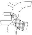
图48示出了主动脉过滤器4803和进入鞘4801的另一个实施例。如图48中所示,进入鞘4801可以通过直接进入(例如切开进入)而通过IA插入,并推进到主动脉,使得进入鞘4801的远端末端终止于或以其他方式定位在升主动脉处、附近或其中。备选地,进入鞘4801可以通过直接切开进入而插入通过右CCA或左CCA,并前进到主动脉。进入鞘4801的远侧末端可以备选地终止于或以其他方式定位在右CCA、左CCA或IA处、附近或其中。FIG. 48 shows another embodiment of an
仍然参考图48,主动脉过滤器4803可以从进入鞘4801的远端延伸并且可以定位在升主动脉内。在一些实施例中,如果进入鞘4801经由左CCA插入,则主动脉过滤器4803也可以部署在主动脉弓的一部分内。在升主动脉内放置主动脉过滤器4803可以防止从主动脉瓣膜释放的栓塞物质被输送到脑循环并可能导致中风。主动脉过滤器4803还可以防止碎片被输送到远侧血管床。Still referring to Figure 48, an
图49显示了进入鞘系统闭合细丝套管的远侧部分的实施例。该系统包括由细长套管形成的外捕获套管4901,其中内轴4910和编织网过滤器4903(附接到内轴4910)可滑动地且同轴地定位。如下文更全面地描述,使用者可以引起内轴4910(和附接的网过滤器4903)和外捕获套管4901之间的相对运动,以释放编织网过滤器4903不受外捕获套管4901的约束。这允许编织网过滤器4903在较小的受约束状态到较大的不受约束的状态之间转换。本文所述的任何过滤器在结构上可以变化,并且可以是例如编织的、网状的、穿孔的等。Figure 49 shows an embodiment of an access sheath system closing the distal portion of the filament cannula. The system includes an
内轴4910具有内管腔,该内管腔的直径尺寸设置成允许穿过其中的鞘(例如TAVR输送鞘)可滑动输送。例如,内轴4910的内径可以是大约18F。编织网过滤器4903可由丝网构造,例如定形镍钛诺丝编织物。
编织网过滤器4903附接到内轴,例如在内轴4910的远端或远侧区域处。编织网过滤器4903可以由诸如镍钛诺丝编织物的定形材料构成。编织网过滤器4903被构造成使得其在不受约束或不受限制时(如图49所示)具有圆锥形状或截头圆锥形状。编织网过滤器4903进一步被构造成可折叠成更小的形状,例如当编织网过滤器4903缩回并约束在外捕获套管4901中时,如下面更全面地描述。The
仍然参考图49,闭合细丝套管4904从内轴4910向外延伸并限定内管腔,闭合细丝4902(例如一段长度的丝)通过该内管腔延伸和突出。闭合细丝4902以允许使用者通过操纵该闭合细丝4902来修改编织网过滤器4903的形状的方式机械地耦联到编织网过滤器4903。例如,闭合细丝4902环绕着编织网过滤器4903的远侧边缘,并环回到闭合细丝套管4904的管腔中。使用者可以将闭合细丝4902抽回或缩回到闭合细丝套管4904中,以沿径向折叠编织网过滤器4903的远侧部分或远侧边缘至闭合,且然后将编织网过滤器4903缩回捕获套管4910中(或将捕获套管4910滑动至编织网过滤器4903之上)。以这种方式,编织网过滤器4910可以折叠成更小的尺寸并且被限制在外捕获套管4910内。Still referring to Figure 49, a
在一些非限制性实施例中,编织网过滤器4903可以利用直径为32mm的一乘二构造编织物,该编织物由大约144根单独的丝组成,诸如,例如0.002″直径的镍钛诺丝。该编织物可以自行折回以提供双层网。双层网比单层网具有优势,例如光滑的远端边缘或边没有暴露的丝末端、更小的网有效细孔大小和/或增加的结构刚度。可以改变网的丝直径、丝数量和编织构造,以调整编织网过滤器4903的刚度/适形性和细孔大小。如图49所示的编织网过滤器4903是双层网,但是层数可以根据编织网过滤器4903的期望特性而有所变化(例如,单层、四层等)。编织网过滤器4903的结构可以补充有额外的支撑特征,例如支柱、箍、环或被构造为增强编织网过滤器4903的整体结构完整性和向外径向力的其他特征,以增加主动脉内的稳定性。另外和/或备选地,编织网过滤器4903的结构可以补充有具有较小细孔大小的附加网状材料(例如,聚对苯二甲酸乙二醇酯(PET)丝、细丝镍钛诺网等)。In some non-limiting embodiments, the
如图50A、50B和50C所示,通过闭合细丝套管4904缩短、拉动或以其他方式致动闭合细丝可以拉动编织网过滤器4903的远侧开口闭合。闭合细丝套管4904可被抽回以将闭合细丝4902和编织网过滤器4903的附接的远侧部分拉入内轴4910的内径,使编织网过滤器4903外翻并减小其外部轮廓。图50A显示了通过闭合细丝套管4904抽出的闭合细丝,从而闭合编织网过滤器4903的远端并将任何栓塞物质捕获在编织网过滤器4903内。拉动编织网过滤器4903闭合可以防止捕获的栓塞物质在编织网过滤器4903的折叠和抽回期间被释放。As shown in Figures 50A, 50B and 50C, shortening, pulling or otherwise actuating the closing filament by closing
图50B示出了闭合细丝套管4904和闭合细丝4902部分缩回以折叠和外翻编织网过滤器4903。也就是说,编织网过滤器4903的圆锥形状外翻到自身上并且随着闭合细丝套管4904和闭合细丝4902缩回而折叠。图50C显示了在折叠的过滤器圆锥5003之上前进的外捕获鞘4901。在编织网过滤器4903折叠之后或在编织网过滤器4903折叠期间,外捕获套管4901可以在编织网过滤器4903上滑动。50B shows
图51A、51B和51C示出了过滤器组件的实施例,其包括具有编织物支撑件5100的织物网过滤器5103。织物网过滤器5103可以是多孔的,诸如,例如具有大约150微米的细孔的织物过滤器.编织物支撑件5100可以是丝编织物,例如镍钛诺丝编织物。编织物支撑件5100被构造为向二级过滤膜(例如织物网过滤器5103)提供支撑网格。在一些实施例中,0.010″镍钛诺丝可用于形成编织物支撑件5100。如图51B中所示,织物网过滤器5103和编织物支撑件5100可以附接到进入鞘5101的远侧部分。相对于进入鞘5101同轴地推进编织物支撑件5100可以增加该结构施加到血管壁的向外径向力。附加地和/或备选地,编织物支撑件5100可以改善织物网过滤器5103靠着主动脉壁的附着,和/或提高织物网过滤器5103在主动脉中的稳定性。51A, 51B and 51C illustrate an embodiment of a filter assembly that includes a
如图51C中所示,相对于进入鞘5101同轴地缩回编织物支撑件5100可以减小组件的外部尺寸以便于部署或收回。例如,编织物支撑件5100的缩回可以使织物网过滤器5103的远侧部分外翻,这可有助于保持由织物网过滤器5103捕获的栓塞物质。图51A示出了织物网过滤器5103,其中编织物支撑件5100附接到织物网过滤器5103的内表面。图51B显示了编织物支撑件5100被完全前进,以向织物网过滤器5103提供额外的向外径向力。图51C显示编织物支撑件5100部分缩回,以部分地外翻织物网过滤器5103的远侧部分以用于颗粒捕获和收回。As shown in Figure 51C, retracting the
在一些实施例中,编织物支撑件5100可以被构造为附接到织物网过滤器5103的外表面,而不是如图51A-51C中所示的织物网过滤器5103的内表面。编织物支撑件5100可备选地定位在两层过滤器材料之间、在过滤器材料内或任何其他合适的构造。附加地和/或备选地,织物网过滤器5103可以被构造为柔韧的或可拉伸的,例如以使织物网过滤器5103能够设置尺寸和/或扩张。织物网过滤器5103的柔韧或拉伸也可以帮助实现更好地贴靠主动脉壁并置。附加地和/或备选地,比图中所示直径更小直径的镍钛诺丝(例如0.006″-0.008″直径)可用于构造编织物支撑件5100。这可产生更加顺应性/柔性的结构,以便使编织物支撑件5100和织物网过滤器5103更好地顺应主动脉壁。应当理解,过滤器材料和编织物材料的其他组合和/或柔性与刚性过滤器或编织物材料的组合可用于实现过滤器和编织物组件的所需特性(例如柔韧性、与主动脉壁的顺应性等)。附加地和/或备选地,织物网过滤器5103可以构造成具有延伸的远侧圆柱形形状,而不是圆锥形或截头圆锥形漏斗形状。这种延伸的远侧圆柱形状可以增加织物网过滤器5103与主动脉壁的表面接触并且提高织物网过滤器5103在定位在主动脉内时的稳定性。In some embodiments, the
图52示出了栓塞保护系统,其包括一对细长的、同轴的、可伸缩的鞘,每个鞘具有内管腔。鞘包括外鞘5205和可滑动地定位在外鞘5205内的同轴内鞘5210。外鞘5205具有可由使用者抓握以操纵外鞘的近侧毂5230。同样,内鞘5210包括从外鞘5205的近端向外向近侧延伸的近侧毂5235。每个毂可以包括相应的出口管线5220,出口管线5220可以包括流量控制装置,例如旋塞阀。Figure 52 shows an embolic protection system comprising a pair of elongated, coaxial, retractable sheaths, each sheath having an inner lumen. The sheath includes an
仍然参考图52,柔性过滤器结构5225附接到内鞘5210的远侧区域,例如在位置5218处。在内鞘5210和外鞘5205之间可以存在间隙5212。在示例实施例中,间隙为至少0.005英寸。过滤器结构5225形成过滤篮,当过滤器结构5225部署在主动脉内时,该过滤篮可用于捕获或转移主动脉内的栓塞物质。过滤器结构5225可以由任何多种材料制造。在一个实施例中,过滤器结构5225由可折叠的镍钛诺编织物构成,该编织物与次微网材料配合。镍钛诺编织物为过滤器结构提供结构和支撑。该编织物还可以促进过滤器结构在定位于其中时抵靠主动脉壁的扩张。例如,微网可以由诸如PET等的材料针织或编织而成。在另一个实施例中,微网由实心片材构成并且穿有孔。微网的孔或细孔大小可以变化并且在一个实施例中在100μm至300μm的范围内,或高达约500μm。微网被构造为允许血液从中通过,同时仍捕获栓塞物质。Still referring to FIG. 52 , a
内导管5210足够大以适应通过其中来定位TAVR输送导管(例如18F或更小的导管)。外导管5205可相对于内导管5210向远侧推进,使得外导管5205捕获、折叠或约束过滤器结构5225,从而促进过滤器结构5225通过血管的管腔的输送。一旦系统已经被输送到目标位置,例如在主动脉处或附近,外导管就可以相对于内导管向近侧抽回,以允许过滤器结构扩张到所需的形状。The
图53A显示了位于主动脉内的过滤器5305的示意图。该过滤器5305可以具有圆锥构造,例如本文所述的任何圆锥状构造。该系统还包括翼过滤器5310,其可以相对于过滤器5305定位在主动脉中。当过滤器5305定位在升主动脉或横向主动脉中时,翼过滤器5310既可以部署也可以定位成跨过或以其他方式覆盖主动脉弓分支处的一根或多根动脉的孔口。该过滤器5305用作主过滤器,其通过捕获主动脉中的栓塞碎片来提供主栓塞保护。翼过滤器5310用作次保护元件,其可以捕获未被过滤器5305捕获的任何栓塞碎片或将栓塞碎片从通向大脑的主动脉分支血管的孔口转移离开。图53A的实施例和图53B的实施例类似地可以从左颈动脉或右颈动脉部署。翼过滤器5310的位置可以相对于过滤器5305的位置有所变化。Figure 53A shows a schematic diagram of a
过滤器5305或翼过滤器5310的细孔大小可以构造为优化过滤器对血流的栓塞捕获。过滤器5305的细孔大小可以调整或以其他方式构造以允许强劲的血流,同时仍捕获栓塞碎片。翼过滤器5310的细孔大小可以被构造为将栓塞物质转向或引导远离从主动脉分支的动脉孔口。翼过滤器5310的较小细孔大小可以抑制未由过滤器5305捕获的较小的栓塞碎片,防止其进入分支动脉中。应当理解,翼过滤器5310不一定必须紧靠动脉孔口齐平放置。翼过滤器5310可以被构造为产生或促进特定的血流模式,例如将血流和任何栓塞颗粒引导到下游并远离分支动脉的孔口。过滤器5305和翼过滤器5310之间细孔大小可以不同,例如以实现流过其中的血液的期望流动模式。在本文所述的任何实施例中,一个或多个孔口可以具有不对称的形状。过滤器的细孔大小可能具有较窄的宽度(例如50μm),其抑制颗粒行进穿过过滤器,同时还具有相对较长的长度(例如800μm),其提供额外的横截面积以降低对通过其中的血流的阻力。The pore size of
图54显示了另一个实施例,其中过滤器5410的尺寸和形状设置为完全定位在主动脉弓内,使得过滤器5410覆盖从主动脉弓分支出来的血管一例如无名动脉、左侧颈动脉和/或左锁骨下动脉一的多个孔口。过滤器5410可以被构造成包括多个区域,其中每个区域具有专用于该区域的细孔大小和形状,并且其中一个区域的细孔大小和/或形状可以不同于另一区域。例如,一个区域可以是具有在50μm至100μm范围内的细孔大小的细网。该区域可以位于或跨越主动脉弓的上面观而定位,以向分支动脉提供栓塞保护。该区域的细孔可能允许血液穿过膜并流入分支动脉。细孔可以足够小以防止栓子通过该区域。Figure 54 shows another embodiment in which the
过滤器5410的另一个区域可以包括具有在150μm至130μm或更大的范围内的细孔大小的粗网。该区域可以覆盖主动脉弓的下部和过滤器5410的远侧封闭部分。相对较大的细孔大小允许血液在该区域中快速流过过滤器。悬浮在血液中的栓塞颗粒可能随血液一起向远侧携带,经过分支血管的孔口。颗粒将被过滤器捕获,以防止它们流入远侧血管床。因此,跨主动脉弓的上面观定位的过滤器5410的细网区域表现为流转向器。应当理解,过滤器5410的每个区域的尺寸、形状和数量可以有所不同。Another area of the
仍然参考图54,该系统可以包括耦联到过滤器5410的框架5405。框架5405可以具有不对称的形状,并且可以由诸如镍钛诺编织物的材料制造。在一个实施例中,该框架包括用于导丝的快速更换端口。Still referring to FIG. 54 , the system can include a
图55示出了另一个实施例,其中过滤器5510包括单件材料,例如单件镍钛诺丝或类似物的编织管。过滤器5510具有形成为诸如篮形或圆柱形的形状的远侧区域,其构造成捕获栓塞物质同时允许血液流过其中。如图55和56中所示,过滤器5510可构造为优化从右颈动脉或左颈动脉输送的定位。过滤器5510构造成为从横主动脉分支的所有动脉提供栓塞保护,并为远侧血管床提供保护。过滤器5510可以包括一个或多个段或区域5520,其被构造为提供增强的向外的径向力,以便增加抵靠主动脉壁的并置。Figure 55 shows another embodiment wherein the
过滤器5510的近侧区域5522可定位在左或右颈动脉内,并扩张至符合颈动脉内径的横截面,例如圆形横截面。过滤器5510的近侧部分可以通过颈动脉的侧壁离开。部分5515可以由材料薄层封装,例如防止血液通过编织物的开孔离开的聚合物层。过滤器5510可以构造有不同的芯尺寸,以促进颗粒的过滤和流动转向,从而抑制这些颗粒行进进入脑循环。The
图58显示了导引器鞘5810的另一个实施例,其耦连到位于鞘5810远端的主过滤器元件5815。辅助过滤器元件5820用作可以为主过滤器元件下游的动脉提供栓塞保护的二级过滤器。FIG. 58 shows another embodiment of an
在一个实施例中,过滤器至少部分地由激光切割的镍钛诺管形成。激光切割管可被定形成所需的形状,例如成圆锥构造。可将具有所需细孔大小的过滤网、网状物或织物附连到镍钛诺框架的内表面或外表面,以提供栓塞保护。In one embodiment, the filter is formed at least in part from laser cut nitinol tube. The laser cut tube can be shaped into a desired shape, such as in a conical configuration. A filter, mesh or fabric of the desired pore size can be attached to the inner or outer surface of the Nitinol frame to provide embolic protection.
虽然本说明书包含许多细节,但这些不应被解释为对要求保护的发明或可能要求保护的内容的范围的限制,而是对特定实施例特有的特征的描述。在本说明书中在单独实施例的上下文中描述的某些特征也可以在单个实施例中组合实施。相反,在单个实施例的上下文中描述的各种特征也可以在多个实施例中单独或以任何合适的子组合来实施。此外,尽管特征可以在上面描述为在某些组合中起作用并且甚至最初如此要求保护,但是在某些情况下可以从组合中去除要求保护的组合中的一个或多个特征,并且要求保护的组合可以针对子组合或子组合的变型。类似地,虽然在附图中以特定顺序描绘了操作,但这不应被理解为要求这些操作以所示的特定顺序或按顺次的顺序执行,或者要求执行所有图示的操作,以实现期望的结果。While this specification contains many details, these should not be construed as limitations on the scope of the claimed invention or what may be claimed, but as descriptions of features specific to particular embodiments. Certain features that are described in this specification in the context of separate embodiments can also be implemented in combination in a single embodiment. Conversely, various features that are described in the context of a single embodiment can also be implemented in multiple embodiments separately or in any suitable subcombination. Furthermore, although features may be described above as functioning in certain combinations and even originally claimed as such, in certain circumstances one or more features of the claimed combination may be removed from the combination and the claimed Combinations can be directed to sub-combinations or variations of sub-combinations. Similarly, although operations in the figures are depicted in a particular order, this should not be construed as requiring the operations to be performed in the particular order shown or sequential order, or that all illustrated operations be performed, in order to achieve desired result.
尽管本文参考某些版本详细描述了各种方法和装置的实施例,但是应当理解,其他版本、实施例、使用方法及其组合也是可能的。因此,所附权利要求的精神和范围不应限于本文包含的实施例的描述。Although embodiments of various methods and apparatus have been described in detail herein with reference to certain versions, it should be understood that other versions, embodiments, methods of use, and combinations thereof are possible. Therefore, the spirit and scope of the appended claims should not be limited to the description of the embodiments contained herein.
Claims (20)
Translated fromChineseApplications Claiming Priority (7)
| Application Number | Priority Date | Filing Date | Title |
|---|---|---|---|
| US201962929357P | 2019-11-01 | 2019-11-01 | |
| US62/929,357 | 2019-11-01 | ||
| US202063014979P | 2020-04-24 | 2020-04-24 | |
| US63/014,979 | 2020-04-24 | ||
| US202063039101P | 2020-06-15 | 2020-06-15 | |
| US63/039,101 | 2020-06-15 | ||
| PCT/US2020/058588WO2021087480A1 (en) | 2019-11-01 | 2020-11-02 | Systems and methods for transcatheter aortic valve treatment |
Publications (1)
| Publication Number | Publication Date |
|---|---|
| CN114901208Atrue CN114901208A (en) | 2022-08-12 |
Family
ID=75715426
Family Applications (1)
| Application Number | Title | Priority Date | Filing Date |
|---|---|---|---|
| CN202080090662.6APendingCN114901208A (en) | 2019-11-01 | 2020-11-02 | Systems and methods for transcatheter aortic valve therapy |
Country Status (5)
| Country | Link |
|---|---|
| US (1) | US20220378565A1 (en) |
| EP (1) | EP4051171A4 (en) |
| JP (1) | JP2022554273A (en) |
| CN (1) | CN114901208A (en) |
| WO (1) | WO2021087480A1 (en) |
Families Citing this family (8)
| Publication number | Priority date | Publication date | Assignee | Title |
|---|---|---|---|---|
| KR20210126681A (en) | 2019-02-13 | 2021-10-20 | 엠볼린, 인크. | Catheter with integrated embolic protection |
| US11844893B2 (en) | 2021-01-17 | 2023-12-19 | Inspire M.D Ltd. | Shunts with blood-flow indicators |
| KR20230147061A (en)* | 2021-02-19 | 2023-10-20 | 엠볼린, 인크. | Method and system for placing embolic filters in the aortic arch |
| US12070542B2 (en) | 2021-03-25 | 2024-08-27 | Inspire M.D Ltd. | Device for shunting blood between the arterial and venous systems |
| ES2921403B2 (en) | 2022-02-03 | 2025-09-09 | Fundacion Para La Investigacion Del Hospital Univ Y Politecnico La Fe De La Comunidad Valenciana | Double-conical coil embolic protection device during endovascular procedures |
| AU2023307656A1 (en)* | 2022-07-09 | 2025-02-20 | Cuddy, Duangnapa Somsuppaphon | First order percutaneous mechanical arterial advanced thrombectomy technology |
| EP4591319A1 (en)* | 2022-09-20 | 2025-07-30 | Koninklijke Philips N.V. | Cerebral embolic protection selection method for tavi procedures |
| WO2024230555A1 (en)* | 2023-05-06 | 2024-11-14 | 深圳市英耐特医疗科技有限公司 | Protective system |
Citations (5)
| Publication number | Priority date | Publication date | Assignee | Title |
|---|---|---|---|---|
| US20160220367A1 (en)* | 2015-02-04 | 2016-08-04 | Medtronic Vascular, Inc. | Balloon valvuloplasty delivery system |
| US20160317288A1 (en)* | 2015-04-30 | 2016-11-03 | Silk Road Medical, Inc. | Systems and methods for transcatheter aortic valve treatment |
| WO2018211344A1 (en)* | 2017-05-17 | 2018-11-22 | Aorticlab Sàrl | Transcatheter valve prosthesis for blood vessel |
| US20190000604A1 (en)* | 2015-09-07 | 2019-01-03 | Filterlex Medical Ltd. | Intra-aortic emboli protection filter device |
| WO2019173475A1 (en)* | 2018-03-07 | 2019-09-12 | Innovative Cardiovascular Solutions, Llc | Embolic protection device |
Family Cites Families (7)
| Publication number | Priority date | Publication date | Assignee | Title |
|---|---|---|---|---|
| FR312E (en) | 1901-12-03 | 1902-12-08 | Rolland Emmanuel | Dyeing machine |
| US6454799B1 (en) | 2000-04-06 | 2002-09-24 | Edwards Lifesciences Corporation | Minimally-invasive heart valves and methods of use |
| US8460335B2 (en) | 2006-09-11 | 2013-06-11 | Embrella Cardiovascular, Inc. | Method of deflecting emboli from the cerebral circulation |
| DK2537488T3 (en)* | 2008-09-04 | 2016-06-27 | Swat Medical Ab | Device for the temporary embolic protection |
| US10779855B2 (en)* | 2011-08-05 | 2020-09-22 | Route 92 Medical, Inc. | Methods and systems for treatment of acute ischemic stroke |
| CA3235511A1 (en)* | 2014-05-21 | 2015-11-26 | Swat Medical Ab | Improved embolic protection device and method |
| US11337790B2 (en)* | 2017-02-22 | 2022-05-24 | Boston Scientific Scimed, Inc. | Systems and methods for protecting the cerebral vasculature |
- 2020
- 2020-11-02CNCN202080090662.6Apatent/CN114901208A/enactivePending
- 2020-11-02EPEP20880426.0Apatent/EP4051171A4/enactivePending
- 2020-11-02USUS17/773,206patent/US20220378565A1/enactivePending
- 2020-11-02JPJP2022525253Apatent/JP2022554273A/enactivePending
- 2020-11-02WOPCT/US2020/058588patent/WO2021087480A1/ennot_activeCeased
Patent Citations (5)
| Publication number | Priority date | Publication date | Assignee | Title |
|---|---|---|---|---|
| US20160220367A1 (en)* | 2015-02-04 | 2016-08-04 | Medtronic Vascular, Inc. | Balloon valvuloplasty delivery system |
| US20160317288A1 (en)* | 2015-04-30 | 2016-11-03 | Silk Road Medical, Inc. | Systems and methods for transcatheter aortic valve treatment |
| US20190000604A1 (en)* | 2015-09-07 | 2019-01-03 | Filterlex Medical Ltd. | Intra-aortic emboli protection filter device |
| WO2018211344A1 (en)* | 2017-05-17 | 2018-11-22 | Aorticlab Sàrl | Transcatheter valve prosthesis for blood vessel |
| WO2019173475A1 (en)* | 2018-03-07 | 2019-09-12 | Innovative Cardiovascular Solutions, Llc | Embolic protection device |
Also Published As
| Publication number | Publication date |
|---|---|
| EP4051171A1 (en) | 2022-09-07 |
| US20220378565A1 (en) | 2022-12-01 |
| WO2021087480A1 (en) | 2021-05-06 |
| EP4051171A4 (en) | 2023-12-20 |
| JP2022554273A (en) | 2022-12-28 |
Similar Documents
| Publication | Publication Date | Title |
|---|---|---|
| JP7527423B2 (en) | Systems and methods for transcatheter aortic valve procedures | |
| US12419744B2 (en) | Systems and methods for transcatheter aortic valve treatment | |
| CN114901208A (en) | Systems and methods for transcatheter aortic valve therapy | |
| US10213288B2 (en) | Distal protection filter | |
| EP1827256B1 (en) | Assembly for distal embolic protection | |
| JP2015510820A (en) | Device for filtering emboli with a filter system connected to the distal end of the sheath during percutaneous aortic valve replacement and repair | |
| WO2023244643A1 (en) | Systems and methods for transcatheter aortic valve treatment |
Legal Events
| Date | Code | Title | Description |
|---|---|---|---|
| PB01 | Publication | ||
| PB01 | Publication | ||
| SE01 | Entry into force of request for substantive examination | ||
| SE01 | Entry into force of request for substantive examination | ||
| TA01 | Transfer of patent application right | ||
| TA01 | Transfer of patent application right | Effective date of registration:20250730 Address after:American Minnesota Applicant after:BOSTON SCIENTIFIC SCIMED, Inc. Country or region after:U.S.A. Address before:California, USA Applicant before:Silk Road Medical, Inc. Country or region before:U.S.A. |