CN114901188A - Dynamic pulley system - Google Patents
Dynamic pulley systemDownload PDFInfo
- Publication number
- CN114901188A CN114901188ACN202080091055.1ACN202080091055ACN114901188ACN 114901188 ACN114901188 ACN 114901188ACN 202080091055 ACN202080091055 ACN 202080091055ACN 114901188 ACN114901188 ACN 114901188A
- Authority
- CN
- China
- Prior art keywords
- pulley
- wire
- tab
- series
- tabs
- Prior art date
- Legal status (The legal status is an assumption and is not a legal conclusion. Google has not performed a legal analysis and makes no representation as to the accuracy of the status listed.)
- Pending
Links
Images


Classifications
- A—HUMAN NECESSITIES
- A61—MEDICAL OR VETERINARY SCIENCE; HYGIENE
- A61B—DIAGNOSIS; SURGERY; IDENTIFICATION
- A61B34/00—Computer-aided surgery; Manipulators or robots specially adapted for use in surgery
- A61B34/70—Manipulators specially adapted for use in surgery
- A61B34/71—Manipulators operated by drive cable mechanisms
- A—HUMAN NECESSITIES
- A61—MEDICAL OR VETERINARY SCIENCE; HYGIENE
- A61B—DIAGNOSIS; SURGERY; IDENTIFICATION
- A61B17/00—Surgical instruments, devices or methods
- A61B2017/00477—Coupling
- A—HUMAN NECESSITIES
- A61—MEDICAL OR VETERINARY SCIENCE; HYGIENE
- A61B—DIAGNOSIS; SURGERY; IDENTIFICATION
- A61B34/00—Computer-aided surgery; Manipulators or robots specially adapted for use in surgery
- A61B34/20—Surgical navigation systems; Devices for tracking or guiding surgical instruments, e.g. for frameless stereotaxis
- A61B2034/2046—Tracking techniques
- A61B2034/2051—Electromagnetic tracking systems
- A—HUMAN NECESSITIES
- A61—MEDICAL OR VETERINARY SCIENCE; HYGIENE
- A61B—DIAGNOSIS; SURGERY; IDENTIFICATION
- A61B34/00—Computer-aided surgery; Manipulators or robots specially adapted for use in surgery
- A61B34/30—Surgical robots
- A61B2034/301—Surgical robots for introducing or steering flexible instruments inserted into the body, e.g. catheters or endoscopes
- A—HUMAN NECESSITIES
- A61—MEDICAL OR VETERINARY SCIENCE; HYGIENE
- A61B—DIAGNOSIS; SURGERY; IDENTIFICATION
- A61B34/00—Computer-aided surgery; Manipulators or robots specially adapted for use in surgery
- A61B34/70—Manipulators specially adapted for use in surgery
- A61B34/71—Manipulators operated by drive cable mechanisms
- A61B2034/715—Cable tensioning mechanisms for removing slack
- A—HUMAN NECESSITIES
- A61—MEDICAL OR VETERINARY SCIENCE; HYGIENE
- A61B—DIAGNOSIS; SURGERY; IDENTIFICATION
- A61B34/00—Computer-aided surgery; Manipulators or robots specially adapted for use in surgery
- A61B34/30—Surgical robots
- A61B34/37—Leader-follower robots
- B—PERFORMING OPERATIONS; TRANSPORTING
- B25—HAND TOOLS; PORTABLE POWER-DRIVEN TOOLS; MANIPULATORS
- B25J—MANIPULATORS; CHAMBERS PROVIDED WITH MANIPULATION DEVICES
- B25J18/00—Arms
- B25J18/02—Arms extensible
- B25J18/04—Arms extensible rotatable
- Y—GENERAL TAGGING OF NEW TECHNOLOGICAL DEVELOPMENTS; GENERAL TAGGING OF CROSS-SECTIONAL TECHNOLOGIES SPANNING OVER SEVERAL SECTIONS OF THE IPC; TECHNICAL SUBJECTS COVERED BY FORMER USPC CROSS-REFERENCE ART COLLECTIONS [XRACs] AND DIGESTS
- Y10—TECHNICAL SUBJECTS COVERED BY FORMER USPC
- Y10T—TECHNICAL SUBJECTS COVERED BY FORMER US CLASSIFICATION
- Y10T74/00—Machine element or mechanism
- Y10T74/19—Gearing
- Y10T74/19642—Directly cooperating gears
- Y10T74/19698—Spiral
- Y10T74/19819—Driven rack or shaft
Landscapes
- Health & Medical Sciences (AREA)
- Life Sciences & Earth Sciences (AREA)
- Surgery (AREA)
- Engineering & Computer Science (AREA)
- Animal Behavior & Ethology (AREA)
- General Health & Medical Sciences (AREA)
- Biomedical Technology (AREA)
- Heart & Thoracic Surgery (AREA)
- Medical Informatics (AREA)
- Molecular Biology (AREA)
- Nuclear Medicine, Radiotherapy & Molecular Imaging (AREA)
- Veterinary Medicine (AREA)
- Public Health (AREA)
- Robotics (AREA)
- Manipulator (AREA)
- Physics & Mathematics (AREA)
- Biophysics (AREA)
- Optics & Photonics (AREA)
- Pathology (AREA)
- Radiology & Medical Imaging (AREA)
Abstract
Description
Translated fromChinese相关申请的交叉引用CROSS-REFERENCE TO RELATED APPLICATIONS
本申请要求于2019年12月31日提交的美国临时申请62/956,001的权益,该美国临时申请据此全文以引用方式并入。This application claims the benefit of US
技术领域technical field
本文所公开的系统和方法涉及医疗器械系统,并且更具体地涉及用于机器人医疗规程的动态滑轮系统。The systems and methods disclosed herein relate to medical device systems and, more particularly, to dynamic pulley systems for robotic medical procedures.
背景技术Background technique
医疗规程诸如内窥镜检查可涉及出于诊断和/或治疗目的而进入患者的解剖结构的内部并使其可视化。例如,胃肠病学、泌尿病学和支气管病学涉及允许医师检查患者管腔诸如输尿管、胃肠道和气道(支气管和细支气管)的医疗规程。在这些规程期间,将细的柔性管状工具或器械诸如内窥镜或导管穿过孔口(诸如自然孔口)插入患者体内并且将其朝向识别用于后续诊断和/或治疗的组织部位推进。医疗器械可以是可控制的和可关节运动的以有利于导航通过解剖结构。Medical procedures such as endoscopy may involve accessing and visualizing the interior of a patient's anatomy for diagnostic and/or therapeutic purposes. For example, gastroenterology, urology, and bronchology involve medical procedures that allow physicians to examine patient lumens such as the ureters, gastrointestinal tract, and airways (bronchioles and bronchioles). During these procedures, a thin, flexible tubular tool or instrument, such as an endoscope or catheter, is inserted into the patient through an orifice, such as a natural orifice, and advanced toward a tissue site identified for subsequent diagnosis and/or treatment. The medical device may be controllable and articulatable to facilitate navigation through anatomy.
附图说明Description of drawings
下文将结合附图描述所公开的方面,该附图被提供以说明而非限制所公开的方面,其中类似的标号表示类似的元件。The disclosed aspects will be described below in conjunction with the accompanying drawings, which are provided to illustrate and not to limit the disclosed aspects, wherein like reference numerals refer to like elements.
图1示出了被布置用于诊断性和/或治疗性支气管镜检查的基于推车的机器人系统的实施方案。Figure 1 shows an embodiment of a cart-based robotic system deployed for diagnostic and/or therapeutic bronchoscopy.
图2描绘了图1的机器人系统的另外方面。FIG. 2 depicts additional aspects of the robotic system of FIG. 1 .
图3示出了被布置用于输尿管镜检查的图1的机器人系统的实施方案。Figure 3 shows an embodiment of the robotic system of Figure 1 deployed for ureteroscopy.
图4示出了被布置用于血管规程的图1的机器人系统的实施方案。Figure 4 shows an embodiment of the robotic system of Figure 1 deployed for vascular procedures.
图5示出了被布置用于支气管镜检查规程的基于台的机器人系统的实施方案。Figure 5 shows an embodiment of a table-based robotic system deployed for a bronchoscopy procedure.
图6提供了图5的机器人系统的另选视图。FIG. 6 provides an alternate view of the robotic system of FIG. 5 .
图7示出了被构造成收起机器人臂的示例性系统。7 illustrates an example system configured to stow a robotic arm.
图8示出了被配置用于输尿管镜检查规程的基于台的机器人系统的实施方案。8 shows an embodiment of a table-based robotic system configured for a ureteroscopy procedure.
图9示出了被构造用于腹腔镜检查规程的基于台的机器人系统的实施方案。Figure 9 shows an embodiment of a table-based robotic system configured for a laparoscopic procedure.
图10示出了图5至图9的具有俯仰和倾斜调节的基于台的机器人系统的实施方案。FIG. 10 shows an embodiment of the table-based robotic system of FIGS. 5-9 with pitch and tilt adjustment.
图11提供了图5至图10的台与基于台的机器人系统的柱之间的接口的详细图示。Figure 11 provides a detailed illustration of the interface between the table of Figures 5-10 and the column of the table-based robotic system.
图12示出了基于台的机器人系统的另选实施方案。Figure 12 shows an alternative embodiment of a table-based robotic system.
图13示出了图12的基于台的机器人系统的端视图。FIG. 13 shows an end view of the table-based robotic system of FIG. 12 .
图14示出了其上附接有机器人臂的基于台的机器人系统的端视图。14 shows an end view of a table-based robotic system with a robotic arm attached thereto.
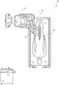
图15示出了示例性器械驱动器。Figure 15 shows an exemplary instrument driver.
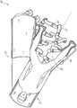
图16示出了具有成对器械驱动器的示例性医疗器械。Figure 16 shows an exemplary medical device with paired device drivers.
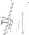
图17示出了器械驱动器和器械的另选设计,其中驱动单元的轴线平行于器械的细长轴的轴线。Figure 17 shows an alternative design of the instrument driver and instrument in which the axis of the drive unit is parallel to the axis of the elongated shaft of the instrument.
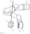
图18示出了具有基于器械的插入架构的器械。Figure 18 shows an instrument with an instrument-based insertion architecture.
图19示出了示例性控制器。Figure 19 shows an example controller.
图20描绘了根据示例性实施方案的框图,该框图示出了估计图1至图10的机器人系统的一个或多个元件的位置(诸如图16至图18的器械的位置)的定位系统。20 depicts a block diagram illustrating a positioning system that estimates the position of one or more elements of the robotic system of FIGS. 1-10, such as the position of the instrument of FIGS. 16-18, according to an exemplary embodiment .
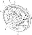
图21A示出了具有以第一构型联接在一起的两个滑轮的动态滑轮系统。Figure 21A shows a dynamic pulley system with two pulleys coupled together in a first configuration.
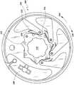
图21B示出了图21A的动态滑轮系统的两个滑轮以第一构型并排定位。Figure 21B shows the two pulleys of the dynamic pulley system of Figure 21A positioned side by side in a first configuration.
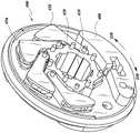
图22A示出了图21A的动态滑轮系统的两个可展开滑轮以第二构型联接在一起。22A shows the two deployable pulleys of the dynamic pulley system of FIG. 21A coupled together in a second configuration.
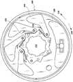
图22B示出了图21A至图22A的动态滑轮系统以第二构型并排定位。22B shows the dynamic pulley systems of FIGS. 21A-22A positioned side-by-side in a second configuration.
图23示出了动态滑轮系统的透视前视图。Figure 23 shows a perspective front view of the dynamic pulley system.
图24示出了图23的动态滑轮系统的透视后视图。FIG. 24 shows a perspective rear view of the dynamic pulley system of FIG. 23 .
图25示出了图23至图24的动态滑轮系统的前视图。Figure 25 shows a front view of the dynamic pulley system of Figures 23-24.
图26示出了图23至图25的动态滑轮系统的后视图。Figure 26 shows a rear view of the dynamic pulley system of Figures 23-25.
图27示出了图23至图26的动态滑轮系统的叶片的透视顶视图。Figure 27 shows a perspective top view of a blade of the dynamic pulley system of Figures 23-26.
图28示出了图27的叶片的透视侧视图。FIG. 28 shows a perspective side view of the blade of FIG. 27 .
图29示出了图23的动态滑轮系统的透视前视图,其中线在叶片上方延伸并且叶片处于展开构型。29 shows a perspective front view of the dynamic pulley system of FIG. 23 with the wire extending over the blades and the blades in a deployed configuration.
图30示出了图29的动态滑轮系统的透视前视图,其中线在叶片上方延伸并且叶片处于塌缩构型。30 shows a perspective front view of the dynamic pulley system of FIG. 29 with the wire extending over the blade and the blade in a collapsed configuration.
图31示出了图23的动态滑轮系统的透视侧视图,其中一对线在叶片上方延伸。Figure 31 shows a perspective side view of the dynamic pulley system of Figure 23 with a pair of wires extending over the blades.
图32示出了具有带四个滑轮的动态滑轮系统的医疗器械。Figure 32 shows a medical device with a dynamic pulley system with four pulleys.
具体实施方式Detailed ways
1.概述。1. Overview .
本公开的各方面可集成到机器人使能的医疗系统中,该机器人使能的医疗系统能够执行多种医疗规程,包括微创规程诸如腹腔镜检查,以及非侵入规程诸如内窥镜检查两者。在内窥镜检查规程中,系统可能能够执行支气管镜检查、输尿管镜检查、胃镜检查等。Aspects of the present disclosure may be integrated into a robotic-enabled medical system capable of performing a variety of medical procedures, including both minimally invasive procedures such as laparoscopy, and non-invasive procedures such as endoscopy . In an endoscopic procedure, the system may be able to perform bronchoscopy, ureteroscopy, gastroscopy, etc.
除了执行广泛的规程之外,系统可以提供附加的益处,诸如增强的成像和指导以帮助医师。另外,该系统可以为医师提供从人体工程学方位执行规程的能力,而不需要笨拙的臂运动和位置。另外,该系统可以为医师提供以改进的易用性执行规程的能力,使得系统的器械中的一个或多个器械可由单个用户控制。In addition to performing a wide range of procedures, the system can provide additional benefits such as enhanced imaging and guidance to assist physicians. Additionally, the system may provide the physician with the ability to perform the procedure from an ergonomic orientation without the need for awkward arm movements and positions. Additionally, the system may provide the physician with the ability to perform the procedure with improved ease of use, such that one or more of the instruments of the system can be controlled by a single user.
出于说明的目的,下文将结合附图描述各种实施方案。应当理解,所公开的概念的许多其他具体实施是可能的,并且利用所公开的具体实施可实现各种优点。标题包括在本文中以供参考并且有助于定位各个节段。这些标题并非旨在限制相对于其所述的概念的范围。此类概念可在整个说明书中具有适用性。For purposes of illustration, various embodiments are described below in conjunction with the accompanying drawings. It should be understood that many other implementations of the disclosed concepts are possible and that various advantages may be realized using the disclosed implementations. Headings are included herein for reference and to assist in locating the various sections. These headings are not intended to limit the scope of the concepts described with respect to them. Such concepts may have applicability throughout the specification.
A.机器人系统-推车。A. Robotic System - Cart .
机器人使能的医疗系统可以按多种方式配置,这取决于特定规程。图1示出了被布置用于诊断性和/或治疗性支气管镜检查的基于推车的机器人使能的系统10的实施方案。在支气管镜检查期间,系统10可包括推车11,该推车具有一个或多个机器人臂12,以将医疗器械诸如可操纵内窥镜13(其可以是用于支气管镜检查的规程特定的支气管镜)递送至自然孔口进入点(即,在本示例中定位在台上的患者的口),以递送诊断和/或治疗工具。如图所示,推车11可被定位在患者的上躯干附近,以便提供到进入点的通路。类似地,可以致动机器人臂12以相对于进入点定位支气管镜。当利用胃镜(用于胃肠道(GI)规程的专用内窥镜)执行GI规程时,也可利用图1中的布置。图2更详细地描绘了推车的示例性实施方案。Robot-enabled medical systems can be configured in a number of ways, depending on the specific protocol. Figure 1 shows an embodiment of a cart-based robot-enabled system 10 deployed for diagnostic and/or therapeutic bronchoscopy. During a bronchoscopy, the system 10 may include a cart 11 having one or more
继续参考图1,一旦推车11被正确定位,机器人臂12就可以机器人地、手动地或以其组合将可操纵内窥镜13插入患者体内。如图所示,可操纵内窥镜13可包括至少两个伸缩部分,诸如内引导件部分和外护套部分,每个部分耦合到来自一组器械驱动器28的单独的器械驱动器,每个器械驱动器耦合到单独的机器人臂的远侧端部。有利于将引导件部分与护套部分同轴对准的器械驱动器28的这种线性布置产生“虚拟轨道”29,该“虚拟轨道”可以通过将一个或多个机器人臂12操纵到不同角度和/或位置而在空间中被重新定位。本文所述的虚拟轨道在附图中使用虚线描绘,并且因此虚线未描绘系统的任何物理结构。器械驱动器28沿着虚拟轨道29的平移使内引导件部分相对于外护套部分伸缩,或者使内窥镜13从患者推进或回缩。虚拟轨道29的角度可以基于临床应用或医师偏好来调节、平移和枢转。例如,在支气管镜检查中,如图所示的虚拟轨道29的角度和方位代表了在向医师提供到内窥镜13的通路同时使由内窥镜13弯曲到患者的口中引起的摩擦最小化之间的折衷。With continued reference to FIG. 1 , once the cart 11 is properly positioned, the
在插入之后,内窥镜13可以使用来自机器人系统的精确命令向下导向患者的气管和肺,直到到达目标目的地或手术部位。为了增强通过患者的肺网络的导航和/或到达期望的目标,内窥镜13可被操纵以从外部护套部分伸缩地延伸内引导件部分,以获得增强的关节运动和更大的弯曲半径。使用单独的器械驱动器28还允许引导件部分和护套部分彼此独立地被驱动。After insertion, the endoscope 13 can be guided down the patient's trachea and lungs using precise commands from the robotic system until the target destination or surgical site is reached. To enhance navigation through the patient's lung network and/or reach a desired target, the endoscope 13 can be manipulated to telescopically extend the inner guide portion from the outer sheath portion for enhanced articulation and a larger bending radius . Using a separate instrument driver 28 also allows the guide portion and sheath portion to be driven independently of each other.
例如,内窥镜13可被导向以将活检针递送到目标,诸如患者肺内的病变或结节。针可沿工作通道向下部署,该工作通道延伸内窥镜的长度以获得待由病理学家分析的组织样本。根据病理结果,可沿内窥镜的工作通道向下部署附加工具以用于附加活检。在识别出结节是恶性的之后,内窥镜13可以通过内窥镜递送工具以切除潜在的癌组织。在一些情况下,诊断和治疗处理可在单独的规程中递送。在这些情况下,内窥镜13也可用于递送基准以“标记”目标结节的位置。在其他情况下,诊断和治疗处理可在相同的规程期间递送。For example, endoscope 13 may be directed to deliver a biopsy needle to a target, such as a lesion or nodule within a patient's lung. The needle can be deployed down a working channel that extends the length of the endoscope to obtain tissue samples to be analyzed by a pathologist. Depending on the pathology results, additional tools may be deployed down the working channel of the endoscope for additional biopsies. After identifying that the nodule is malignant, the endoscope 13 can deliver a tool through the endoscope to resect the underlying cancerous tissue. In some cases, diagnostic and therapeutic treatments may be delivered in separate procedures. In these cases, the endoscope 13 may also be used to deliver fiducials to "mark" the location of the target nodule. In other cases, diagnostic and therapeutic treatments can be delivered during the same procedure.
系统10还可包括可运动塔30,该可运动塔可经由支撑缆线连接到推车11以向推车11提供控制、电子、流体、光学、传感器和/或电力的支持。将这样的功能放置在塔30中允许可以由操作医师和他/她的工作人员更容易地调节和/或重新定位的更小形状因子的推车11。另外,在推车/台和支撑塔30之间划分功能减少了手术室混乱并且有利于改善临床工作流程。虽然推车11可被定位成靠近患者,但是塔30可以在远程位置中被收起以在规程过程期间不挡道。The system 10 may also include a movable tower 30 that may be connected to the cart 11 via support cables to provide control, electronic, fluid, optical, sensor and/or electrical support to the cart 11 . Placing such functionality in the tower 30 allows for a smaller form factor cart 11 that can be more easily adjusted and/or repositioned by the operating physician and his/her staff. Additionally, dividing functions between the cart/table and support tower 30 reduces operating room clutter and facilitates improved clinical workflow. While the cart 11 can be positioned close to the patient, the tower 30 can be stowed in a remote location to stay out of the way during the procedure.
为了支持上述机器人系统,塔30可包括基于计算机的控制系统的部件,该基于计算机的控制系统将计算机程序指令存储在例如非暂态计算机可读存储介质诸如永磁存储驱动器、固态驱动器等内。无论执行是发生在塔30中还是发生在推车11中,这些指令的执行都可以控制整个系统或其子系统。例如,当由计算机系统的处理器执行时,指令可致使机器人系统的部件致动相关托架和臂安装件,致动机器人臂,并且控制医疗器械。例如,响应于接收到控制信号,机器人臂的接头中的马达可将臂定位成特定姿势。To support the robotic system described above, tower 30 may include components of a computer-based control system that stores computer program instructions, eg, within a non-transitory computer-readable storage medium such as a permanent magnet storage drive, solid state drive, or the like. Whether execution occurs in tower 30 or cart 11, execution of these instructions can control the entire system or its subsystems. For example, when executed by a processor of a computer system, the instructions may cause components of the robotic system to actuate the associated brackets and arm mounts, actuate the robotic arm, and control the medical instrument. For example, in response to receiving a control signal, a motor in a joint of a robotic arm may position the arm into a particular pose.
塔30还可包括泵、流量计、阀控制器和/或流体通路,以便向可通过内窥镜13部署的系统提供受控的冲洗和抽吸能力。这些部件也可使用塔30的计算机系统来控制。在一些实施方案中,冲洗和抽吸能力可通过单独的缆线直接递送到内窥镜13。Tower 30 may also include pumps, flow meters, valve controls, and/or fluid pathways to provide controlled irrigation and aspiration capabilities to the system deployable through endoscope 13 . These components may also be controlled using the tower 30 computer system. In some embodiments, irrigation and suction capabilities can be delivered directly to endoscope 13 via separate cables.
塔30可包括电压和浪涌保护器,该电压和浪涌保护器被设计成向推车11提供经滤波和保护的电力,从而避免在推车11中放置电力变压器和其他辅助电力部件,从而得到更小、更可运动的推车11。Tower 30 may include voltage and surge protectors designed to provide filtered and protected power to cart 11, thereby avoiding placement of power transformers and other auxiliary power components in cart 11, thereby A smaller, more mobile cart 11 is obtained.
塔30还可包括用于在整个机器人系统10中部署的传感器的支撑设备。例如,塔30可包括用于在整个机器人系统10中检测、接收和处理从光学传感器或相机接收的数据的光电设备。结合控制系统,此类光电设备可用于生成实时图像,以用于在整个系统中部署的任何数量的控制台中显示(包括在塔30中显示)。类似地,塔30还可包括用于接收和处理从部署的电磁(EM)传感器接收的信号的电子子系统。塔30还可用于容纳和定位EM场发生器,以便由医疗器械中或医疗器械上的EM传感器进行检测。Tower 30 may also include support equipment for sensors deployed throughout robotic system 10 . For example, tower 30 may include optoelectronic devices for detecting, receiving, and processing data received from optical sensors or cameras throughout robotic system 10 . In conjunction with the control system, such optoelectronic devices can be used to generate real-time images for display in any number of consoles deployed throughout the system (including in tower 30). Similarly, tower 30 may also include electronic subsystems for receiving and processing signals received from deployed electromagnetic (EM) sensors. Tower 30 may also be used to house and position EM field generators for detection by EM sensors in or on the medical device.
除了系统的其余部分中可用的其他控制台(例如,安装在推车顶部上的控制台)之外,塔30还可包括控制台31。控制台31可包括用于医师操作者的用户界面和显示屏,诸如触摸屏。系统10中的控制台通常设计成提供机器人控制以及规程的术前信息和实时信息两者,诸如内窥镜13的导航和定位信息。当控制台31不是医师可用的唯一控制台时,其可由第二操作者(诸如护士)使用以监测患者的健康状况或生命体征和系统10的操作,以及提供规程特定的数据,诸如导航和定位信息。在其他实施方案中,控制台30被容纳在与塔30分开的主体中。Tower 30 may include console 31 in addition to other consoles available in the rest of the system (eg, a console mounted on top of a cart). Console 31 may include a user interface and a display screen, such as a touch screen, for a physician operator. The console in system 10 is typically designed to provide both preoperative and real-time information for robotic control as well as procedures, such as endoscope 13 navigation and positioning information. When the console 31 is not the only console available to the physician, it may be used by a second operator, such as a nurse, to monitor the patient's health or vital signs and operation of the system 10, as well as to provide procedure-specific data such as navigation and positioning information. In other embodiments, the console 30 is housed in a body separate from the tower 30 .
塔30可通过一个或多个缆线或连接件(未示出)耦合到推车11和内窥镜13。在一些实施方案中,可通过单根缆线向推车11提供来自塔30的支撑功能,从而简化手术室并消除手术室的混乱。在其他实施方案中,特定功能可耦合在单独的布线和连接中。例如,虽然可以通过单个缆线向推车11提供电力,但也可以通过单独的缆线提供对控件、光学器件、流体和/或导航的支持。Tower 30 may be coupled to cart 11 and endoscope 13 by one or more cables or connections (not shown). In some embodiments, the support function from tower 30 may be provided to cart 11 by a single cable, thereby simplifying and eliminating clutter in the operating room. In other embodiments, certain functions may be coupled in separate wiring and connections. For example, while power may be provided to the cart 11 via a single cable, support for controls, optics, fluids, and/or navigation may also be provided via separate cables.
图2提供了来自图1所示的基于推车的机器人使能的系统的推车11的实施方案的详细图示。推车11通常包括细长支撑结构14(通常称为“柱”)、推车基部15以及在柱14的顶部处的控制台16。柱14可包括一个或多个托架,诸如用于支持一个或多个机器人臂12(图2中示出三个)的部署的托架17(另选地为“臂支撑件”)。托架17可包括可单独配置的臂安装件,该臂安装件沿垂直轴线旋转以调节机器人臂12的基部,以相对于患者更好地定位。托架17还包括托架接口19,该托架接口允许托架17沿着柱14竖直地平移。FIG. 2 provides a detailed illustration of an embodiment of a cart 11 from the cart-based robotic-enabled system shown in FIG. 1 . The cart 11 generally includes an elongated support structure 14 (commonly referred to as a "post"), a cart base 15 and a console 16 at the top of the post 14 . The column 14 may include one or more brackets, such as brackets 17 (alternatively "arm supports") for supporting the deployment of one or more robotic arms 12 (three are shown in FIG. 2 ). The
托架接口19通过狭槽诸如狭槽20连接到柱14,该狭槽定位在柱14的相对侧上以引导托架17的竖直平移。狭槽20包括竖直平移接口以将托架17相对于推车基部15定位并保持在各种竖直高度处。托架17的竖直平移允许推车11调节机器人臂12的到达范围以满足各种台高度、患者尺寸和医师偏好。类似地,托架17上的可单独配置的臂安装件允许机器人臂12的机器人臂基部21以多种配置成角度。Bracket interface 19 is connected to post 14 by a slot, such as slot 20 , positioned on opposite sides of post 14 to guide vertical translation of
在一些实施方案中,狭槽20可补充有狭槽盖,该狭槽盖与狭槽表面齐平且平行,以防止灰尘和流体在托架17竖直平移时进入柱14的内部腔以及竖直平移接口。狭槽盖可通过定位在狭槽20的竖直顶部和底部附近的成对弹簧卷轴部署。盖在卷轴内盘绕,直到在托架17竖直地上下平移时被部署成从盖的盘绕状态延伸和回缩。当托架17朝向卷轴平移时,卷轴的弹簧加载提供了将盖回缩到卷轴中的力,同时在托架17平移远离卷轴时也保持紧密密封。可使用例如托架接口19中的支架将盖连接到托架17,以确保在托架17平移时盖的适当延伸和回缩。In some embodiments, the slot 20 may be supplemented with a slot cover that is flush and parallel to the slot surface to prevent dirt and fluids from entering the interior cavity of the column 14 and vertical vertical translation of the
柱14可在内部包括诸如齿轮和马达之类的机构,其被设计成使用竖直对准的导螺杆以响应于响应用户输入(例如,来自控制台16的输入)生成的控制信号来以机械化方式平移托架17。Column 14 may internally include mechanisms such as gears and motors designed to mechanize using vertically aligned lead screws in response to control signals generated in response to user input (eg, input from console 16 ). way to translate the
机器人臂12通常可包括由一系列连杆23分开的机器人臂基部21和端部执行器22,该一系列连杆由一系列接头24连接,每个接头包括独立的致动器,每个致动器包括可独立控制的马达。每个可独立控制的接头表示机器人臂12可用的独立自由度。机器人臂12中的每个机器人臂可具有七个接头,并且因此提供七个自由度。多个接头导致多个自由度,从而允许“冗余”的自由度。具有冗余自由度允许机器人臂12使用不同的连接件位置和接头角度将其相应的端部执行器22定位在空间中的特定方位、取向和轨迹处。这允许系统从空间中的期望点定位和导向医疗器械,同时允许医师使臂关节运动到远离患者的临床有利方位,以产生更大的接近,同时避免臂碰撞。The
推车基部15在地板上平衡柱14、托架17和机器人臂12的重量。因此,推车基部15容纳较重的部件,诸如电子器件、马达、电源以及使得推车11能够运动和/或固定的部件。例如,推车基部15包括允许推车11在规程之前容易地围绕房间运动的可滚动的轮形脚轮25。在到达适当方位之后,脚轮25可以使用轮锁固定,以在规程期间将推车11保持在适当方位。The cart base 15 balances the weight of the columns 14,
定位在柱14的竖直端部处的控制台16允许用于接收用户输入的用户界面和显示屏(或两用装置,诸如例如触摸屏26)两者向医师用户提供术前和术中数据两者。触摸屏26上的潜在术前数据可以包括从术前计算机化断层摄影(CT)扫描导出的术前计划、导航和标测数据和/或来自术前患者面谈的记录。显示器上的术中数据可以包括从工具、传感器提供的光学信息和来自传感器的坐标信息以及重要的患者统计,诸如呼吸、心率和/或脉搏。控制台16可以被定位和倾斜成允许医师从柱14的与托架17相对的侧面进入控制台16。从该方位,医师可以在从推车11后面操作控制台16的同时观察控制台16、机器人臂12和患者。如图所示,控制台16还包括用以帮助操纵和稳定推车11的柄部27。The console 16 positioned at the vertical end of the column 14 allows both a user interface for receiving user input and a display screen (or a dual-use device such as, for example, a touch screen 26) to provide both preoperative and intraoperative data to the physician user. By. Potential preoperative data on touch screen 26 may include preoperative planning, navigation and mapping data derived from preoperative computerized tomography (CT) scans and/or records from preoperative patient interviews. Intraoperative data on the display may include optical information provided from tools, sensors and coordinate information from sensors as well as important patient statistics such as respiration, heart rate and/or pulse. Console 16 may be positioned and tilted to allow physician access to console 16 from the side of column 14
图3示出了被布置用于输尿管镜检查的机器人使能的系统10的实施方案。在输尿管镜规程中,推车11可被定位成将输尿管镜32(被设计成横穿患者的尿道和输尿管的规程特定的内窥镜)递送到患者的下腹部区域。在输尿管镜检查中,可以期望输尿管镜32直接与患者的尿道对准以减少该区域中的敏感解剖结构上的摩擦和力。如图所示,推车11可以在台的脚部处对准,以允许机器人臂12定位输尿管镜32,以用于直接线性进入患者的尿道。机器人臂12可从台的脚部沿着虚拟轨道33将输尿管镜32通过尿道直接插入患者的下腹部中。Figure 3 shows an embodiment of a robot-enabled system 10 deployed for ureteroscopy. In a ureteroscopic procedure, the cart 11 may be positioned to deliver a ureteroscope 32 (a procedure-specific endoscope designed to traverse a patient's urethra and ureter) to the patient's lower abdominal region. In ureteroscopy, it may be desirable to align the ureteroscope 32 directly with the patient's urethra to reduce friction and forces on sensitive anatomy in this region. As shown, the cart 11 may be aligned at the feet of the table to allow the
在插入到尿道中之后,使用与支气管镜检查中类似的控制技术,输尿管镜32可以被导航到膀胱、输尿管和/或肾中以用于诊断和/或治疗应用。例如,可以将输尿管镜32引导到输尿管和肾中以使用沿输尿管镜32的工作通道向下部署的激光或超声碎石装置来打碎积聚的肾结石。在碎石完成之后,可以使用沿输尿管镜32向下部署的篮移除所得的结石碎片。After insertion into the urethra, the ureteroscope 32 can be navigated into the bladder, ureter and/or kidney for diagnostic and/or therapeutic applications using similar control techniques as in bronchoscopy. For example, the ureteroscope 32 can be guided into the ureter and kidney to break up accumulated kidney stones using a laser or ultrasonic lithotripsy device deployed down the working channel of the ureteroscope 32 . After lithotripsy is complete, the resulting stone fragments can be removed using a basket deployed down the ureteroscope 32.
图4示出了类似地布置用于血管规程的机器人使能的系统10的实施方案。在血管规程中,系统10可被配置成使得推车11可将医疗器械34(诸如可操纵导管)递送至患者的腿部的股动脉中的接入点。股动脉呈现用于导航的较大直径以及到患者的心脏的相对较少的迂回且曲折的路径两者,这简化了导航。如在输尿管镜规程中,推车11可以被定位成朝向患者的腿部和下腹部,以允许机器人臂12提供直接线性进入患者的大腿/髋部区域中的股动脉接入点的虚拟轨道35。在插入到动脉中之后,可通过平移器械驱动器28来导向和插入医疗器械34。另选地,推车可以被定位在患者的上腹部周围,以到达另选的血管进入点,诸如肩部和腕部附近的颈动脉和臂动脉。FIG. 4 shows an embodiment of the robotic-enabled system 10 similarly deployed for vascular procedures. In a vascular procedure, the system 10 may be configured such that the cart 11 may deliver a medical device 34, such as a steerable catheter, to an access point in the femoral artery of the patient's leg. The femoral artery presents both a larger diameter for navigation and a relatively less circuitous and tortuous path to the patient's heart, which simplifies navigation. As in a ureteroscopic procedure, the cart 11 may be positioned towards the patient's legs and lower abdomen to allow the
B.机器人系统-台。B. Robotic System - Station .
机器人使能的医疗系统的实施方案还可结合患者的台。结合台通过移除推车减少了手术室内的资本设备的量,这允许更多地接近患者。图5示出了被布置用于支气管镜检查规程的这样的机器人使能的系统的实施方案。系统36包括用于将平台38(示出为“台”或“床”)支撑在地板上的支撑结构或柱37。与基于推车的系统非常相似,系统36的机器人臂39的端部执行器包括器械驱动器42,其被设计成通过或沿着由器械驱动器42的线性对准形成的虚拟轨道41来操纵细长医疗器械,诸如图5中的支气管镜40。在实践中,用于提供荧光镜成像的C形臂可以通过将发射器和检测器放置在台38周围而定位在患者的上腹部区域上方。Embodiments of the robotic-enabled medical system may also incorporate a patient's table. Incorporating the table reduces the amount of capital equipment in the operating room by removing the cart, which allows greater access to the patient. Figure 5 shows an embodiment of such a robot-enabled system deployed for a bronchoscopy procedure.
图6提供了用于讨论目的的没有患者和医疗器械的系统36的另选视图。如图所示,柱37可包括在系统36中示出为环形的一个或多个托架43,一个或多个机器人臂39可基于该托架。托架43可以沿着沿柱37的长度延伸的竖直柱接口44平移,以提供不同的有利点,机器人臂39可以从这些有利点被定位以到达患者。托架43可以使用定位在柱37内的机械马达围绕柱37旋转,以允许机器人臂39进入台38的多个侧面,诸如患者的两侧。在具有多个托架的实施方案中,托架可单独地定位在柱上,并且可独立于其他托架平移和/或旋转。虽然托架43不需要环绕柱37或甚至是圆形的,但如图所示的环形形状有利于托架43围绕柱37旋转,同时保持结构平衡。托架43的旋转和平移允许系统36将医疗器械诸如内窥镜和腹腔镜对准到患者上的不同接入点中。在其他实施方案(未示出)中,系统36可包括具有可调式臂支撑件的病人检查台或病床,该可调式臂支撑件呈在病人检查台或病床旁边延伸的杆或导轨的形式。一个或多个机器人臂39(例如,经由具有肘接头的肩部)可附接到可调式臂支撑件,该可调式臂支撑件可被竖直调节。通过提供竖直调节,机器人臂39有利地能够紧凑地存放在病人检查台或病床下方,并且随后在规程期间升高。FIG. 6 provides an alternate view of the
机器人臂39可通过包括一系列接头的一组臂安装件45安装在托架43上,该接头可单独地旋转和/或伸缩地延伸以向机器人臂39提供附加的可配置性。另外,臂安装件45可定位在托架43上,使得当托架43适当地旋转时,臂安装件45可定位在台38的同一侧上(如图6所示)、台38的相对侧上(如图9所示)或台38的相邻侧上(未示出)。The
柱37在结构上为台38提供支撑,并且为托架43的竖直平移提供路径。在内部,柱37可配备有用于引导托架的竖直平移的导螺杆,以及用以机械化基于导螺杆的托架43的平移的马达。柱37还可将功率和控制信号传送到托架43和安装在其上的机器人臂39。
台基部46具有与图2所示的推车11中的推车基部15类似的功能,容纳较重的部件以平衡台/床38、柱37、托架43和机器人臂39。台基部46还可结合刚性脚轮以在规程期间提供稳定性。从台基部46的底部部署的脚轮可以在基部46的两侧沿相反方向延伸,并且当系统36需要运动时回缩。The
继续图6,系统36还可以包括塔(未示出),该塔使系统36的功能在台与塔之间进行划分以减小台的形状因子和体积。如在先前所公开的实施方案中,塔可以向台提供多种支持功能,诸如处理、计算和控制能力、电力、流体和/或光学以及传感器处理。塔还可以是可运动的,以远离患者定位,从而改善医师的接近并且消除手术室的混乱。另外,将部件放置在塔中允许在台基部46中有更多的储存空间,以用于机器人臂39的潜在收起。塔还可以包括主控制器或控制台,其提供用于用户输入的用户界面(诸如键盘和/或挂件)以及用于术前和术中信息(诸如实时成像、导航和跟踪信息)的显示屏(或触摸屏)两者。在一些实施方案中,塔还可包括用于待用于注气的气罐的夹持器。Continuing with Figure 6, the
在一些实施方案中,台基部可以在不使用时收起和储存机器人臂。图7示出了在基于台的系统的实施方案中收起机器人臂的系统47。在系统47中,托架48可以竖直平移到基部49中以使机器人臂50、臂安装件51和托架48收起在基部49内。基部盖52可以平移和回缩打开以围绕柱53部署托架48、臂安装件51和机器人臂50,并且闭合以收起该托架、臂安装件和机器人臂,以便在不使用时保护它们。基部盖52可以利用膜54沿着其开口的边缘密封,以防止在闭合时灰尘和流体进入。In some embodiments, the table base can stow and store the robotic arm when not in use. Figure 7 shows the system 47 for retracting the robotic arm in an embodiment of the table-based system. In system 47 ,
图8示出了被配置用于输尿管镜检查规程的机器人使能的基于台的系统的实施方案。在输尿管镜检查中,台38可以包括用于将患者定位成与柱37和台基部46成偏角的旋转部分55。旋转部分55可以围绕枢转点(例如,位于患者的头部下方)旋转或枢转,以便将旋转部分55的底部部分定位成远离柱37。例如,旋转部分55的枢转允许C形臂(未示出)定位在患者的下腹部上方,而不与台38下方的柱(未示出)竞争空间。通过围绕柱37旋转托架35(未示出),机器人臂39可以沿着虚拟轨道57将输尿管镜56直接插入患者的腹股沟区域中以到达尿道。在输尿管镜检查中,镫58也可以固定至台38的旋转部分55,以在手术期间支撑患者的腿部的方位,并且允许完全通向患者的腹股沟区域。8 shows an embodiment of a robotic-enabled table-based system configured for a ureteroscopy procedure. In ureteroscopy, the table 38 may include a rotating portion 55 for positioning the patient at an off-angle to the
在腹腔镜检查规程中,通过患者的腹壁中的一个或多个小切口,可将微创器械插入患者的解剖结构中。在一些实施方案中,微创器械包括用于进入患者内的解剖结构的细长刚性构件,诸如轴。在患者腹腔充气之后,可以引导器械执行外科或医疗任务,诸如抓握、切割、消融、缝合等。在一些实施方案中,器械可以包括镜,诸如腹腔镜。图9示出了被配置用于腹腔镜检查规程的机器人使能的基于台的系统的实施方案。如图9所示,系统36的托架43可以被旋转并且竖直调整,以将成对的机器人臂39定位在台38的相对侧上,使得可以使用臂安装件45将器械59定位成穿过患者两侧上的最小切口以到达他/她的腹腔。In a laparoscopic procedure, minimally invasive instruments can be inserted into a patient's anatomy through one or more small incisions in the patient's abdominal wall. In some embodiments, the minimally invasive instrument includes an elongated rigid member, such as a shaft, for accessing anatomical structures within a patient. After inflation of the patient's abdominal cavity, the instrument can be directed to perform surgical or medical tasks, such as grasping, cutting, ablation, suturing, and the like. In some embodiments, the instrument may include a scope, such as a laparoscope. 9 illustrates an embodiment of a robotic-enabled table-based system configured for a laparoscopic procedure. As shown in FIG. 9 , the
为了适应腹腔镜检查规程,机器人使能的台系统还可将平台倾斜到期望的角度。图10示出了具有俯仰或倾斜调整的机器人使能的医疗系统的实施方案。如图10所示,系统36可以适应台38的倾斜,以将台的一部分定位在比另一部分距底板更远的距离处。另外,臂安装件45可以旋转以匹配倾斜,使得机器人臂39与台38保持相同的平面关系。为了适应更陡的角度,柱37还可以包括伸缩部分60,该伸缩部分允许柱37的竖直延伸以防止台38接触地板或与台基部46碰撞。To accommodate laparoscopy procedures, the robotic-enabled table system can also tilt the platform to a desired angle. Figure 10 shows an embodiment of a robot-enabled medical system with pitch or tilt adjustment. As shown in FIG. 10, the
图11提供了台38与柱37之间的接口的详细图示。俯仰旋转机构61可以被配置成以多个自由度改变台38相对于柱37的俯仰角。俯仰旋转机构61可以通过将正交轴线1、2定位在柱台接口处来实现,每条轴线由单独的马达3、4响应于电俯仰角命令而致动。沿着一个螺钉5的旋转将使得能够在一条轴线1中进行倾斜调整,而沿着另一个螺钉6的旋转将使得能够沿着另一个轴线2进行倾斜调节。在一些实施方案中,可使用球形接头来在多个自由度上改变台38相对于柱37的俯仰角。FIG. 11 provides a detailed illustration of the interface between
例如,当试图将台定位在头低脚高位(即,将患者的下腹部定位在比患者的上腹部距地板更高的方位)以用于下腹部手术时,俯仰调节特别有用。头低脚高位致使患者的内部器官通过重力滑向他/她的上腹部,从而清理出腹腔以使微创工具进入并且执行下腹部外科或医疗规程,诸如腹腔镜前列腺切除术。Pitch adjustment is particularly useful, for example, when attempting to position the table in a head-down position (ie, positioning the patient's lower abdomen in an orientation higher from the floor than the patient's upper abdomen) for lower abdominal surgery. The head-down position causes the patient's internal organs to slide by gravity toward his/her upper abdomen, thereby clearing the abdominal cavity to allow minimally invasive tools to enter and perform lower abdominal surgical or medical procedures, such as laparoscopic prostatectomy.
图12和图13示出了基于台的外科机器人系统100的另选实施方案的等轴视图和端视图。外科机器人系统100包括可被构造成相对于台101支撑一个或多个机器人臂(参见例如图14)的一个或多个可调式臂支撑件105。在例示的实施方案中,示出了单个可调式臂支撑件105,但是附加的臂支撑件可设置在台101的相对侧上。可调式臂支撑件105可被构造,使得其可相对于台101运动,以调节和/或改变可调式臂支撑件105和/或安装到该可调式臂支撑件的任何机器人臂相对于台101的方位。例如,可调式臂支撑件105可相对于台101被调节一个或多个自由度。可调式臂支撑件105为系统100提供高灵活性,包括容易地将一个或多个可调式臂支撑件105和附接到其的任何机器人臂收起在台101下方的能力。可调式臂支撑件105可从收起方位升高到台101的上表面下方的方位。在其他实施方案中,可调式臂支撑件105可从收起方位升高到台101的上表面上方的方位。FIGS. 12 and 13 show isometric and end views of an alternate embodiment of a table-based surgical
可调式臂支撑件105可提供若干自由度,包括提升、侧向平移、倾斜等。在图12和图13的例示实施方案中,臂支撑件105被构造成具有四个自由度,这些自由度在图12中用箭头示出。第一自由度允许在z方向上(“Z提升”)调节可调式臂支撑件105。例如,可调式臂支撑件105可包括托架109,该托架被配置成沿或相对于支撑台101的柱102向上或向下运动。第二自由度可允许可调式臂支撑件105倾斜。例如,可调式臂支撑件105可包括旋转接头,该旋转接头可允许可调式臂支撑件105在头低脚高位与床对准。第三自由度可允许可调式臂支撑件105“向上枢转”,这可用于调节台101的一侧与可调式臂支撑件105之间的距离。第四自由度可允许可调式臂支撑件105沿台的纵向长度平移。The
图12和图13中的外科机器人系统100可包括由安装到基部103的柱102支撑的台。基部103和柱102相对于支撑表面支撑台101。地板轴线131和支撑轴线133在图13中示出。The surgical
可调式臂支撑件105可安装到柱102。在其他实施方案中,臂支撑件105可安装到台101或基部103。可调式臂支撑件105可包括托架109、杆或导轨连接件111以及杆或导轨107。在一些实施方案中,安装到轨道107的一个或多个机器人臂可相对于彼此平移和运动。An
托架109可通过第一接头113附接到柱102,该第一接头允许托架109相对于柱102运动(例如,诸如沿第一轴线或竖直轴线123上下运动)。第一接头113可向可调式臂支撑件105提供第一自由度(“Z提升”)。可调式臂支撑件105可包括第二接头115,该第二接头为可调式臂支撑件105提供第二自由度(倾斜)。可调式臂支撑件105可包括第三接头117,该第三接头可为可调式臂支撑件105提供第三自由度(“向上枢转”)。可提供附加接头119(在图13中示出),该附加接头机械地约束第三接头117以在导轨连接件111围绕第三轴线127旋转时保持导轨107的取向。可调式臂支撑件105可包括第四接头121,该第四接头可沿第四轴线129为可调式臂支撑件105提供第四自由度(平移)。
图14示出了根据一个实施方案的具有安装在台101的相对侧上的两个可调式臂支撑件105A、105B的外科机器人系统140A的端视图。第一机器人臂142A附接到第一可调式臂支撑件105B的杆或导轨107A。第一机器人臂142A包括附接到导轨107A的基部144A。第一机器人臂142A的远侧端部包括可附接到一个或多个机器人医疗器械或工具的器械驱动机构146A。类似地,第二机器人臂142B包括附接到导轨107B的基部144B。第二机器人臂142B的远侧端部包括器械驱动机构146B。器械驱动机构146B可被构造成附接到一个或多个机器人医疗器械或工具。14 shows an end view of a surgical
在一些实施方案中,机器人臂142A、142B中的一者或多者包括具有七个或更多个自由度的臂。在一些实施方案中,机器人臂142A、142B中的一者或多者可包括八个自由度,包括插入轴线(包括插入的1个自由度)、腕部(包括腕部俯仰、偏航和滚动的3个自由度)、肘部(包括肘部俯仰的1个自由度)、肩部(包括肩部俯仰和偏航的2个自由度)以及基部144A、144B(包括平移的1个自由度)。在一些实施方案中,插入自由度可由机器人臂142A、142B提供,而在其他实施方案中,器械本身经由基于器械的插入架构提供插入。In some implementations, one or more of the
C.器械驱动器和接口。C. Instrument Drivers and Interfaces .
系统的机器人臂的端部执行器可包括:(i)器械驱动器(另选地称为“器械驱动机构”或“器械装置操纵器”),该器械驱动器结合了用于致动医疗器械的机电装置;以及(ii)可移除或可拆卸的医疗器械,该医疗器械可以没有任何机电部件,诸如马达。该二分法可能是由以下所驱动的:对医疗规程中使用的医疗器械进行灭菌的需要;以及由于昂贵的资本设备的复杂机械组件和敏感电子器件而不能对昂贵的资本设备进行充分灭菌。因此,医疗器械可以被设计成从器械驱动器(以及因此从系统)拆卸、移除和互换,以便由医师或医师的工作人员单独灭菌或处置。相比之下,器械驱动器不需要被改变或灭菌,并且可以被覆盖以便保护。The end effector of the robotic arm of the system may include: (i) an instrument driver (alternatively referred to as an "instrument drive mechanism" or "instrument device manipulator") that incorporates electromechanical mechanisms for actuating medical instruments device; and (ii) a removable or detachable medical device, which may be devoid of any electromechanical components, such as a motor. This dichotomy may be driven by: the need to sterilize medical devices used in medical procedures; and the inability to adequately sterilize expensive capital equipment due to its complex mechanical components and sensitive electronics . Accordingly, medical instruments can be designed to be detached, removed, and interchanged from the instrument driver (and thus the system) for individual sterilization or disposal by a physician or physician's staff. In contrast, the instrument driver does not need to be altered or sterilized, and can be covered for protection.
图15示出了示例器械驱动器。定位在机器人臂的远侧端部处的器械驱动器62包括一个或多个驱动单元63,该一个或多个驱动单元以平行轴线布置以经由驱动轴64向医疗器械提供受控扭矩。每个驱动单元63包括用于与器械相互作用的单独的驱动轴64,用于将马达轴旋转转换成期望扭矩的齿轮头65,用于生成驱动扭矩的马达66,用以测量马达轴的速度并且向控制电路提供反馈的编码器67,以及用于接收控制信号并且致动驱动单元的控制电路68。每个驱动单元63被独立地控制和机动化,器械驱动器62可向医疗器械提供多个(例如,如图15所示为四个)独立的驱动输出。在操作中,控制电路68将接收控制信号,将马达信号传输至马达66,将由编码器67测量的所得马达速度与期望速度进行比较,并且调制马达信号以生成期望扭矩。Figure 15 shows an example instrument driver. An
对于需要无菌环境的规程,机器人系统可以结合驱动接口,诸如连接至无菌覆盖件的无菌适配器,其位于器械驱动器与医疗器械之间。无菌适配器的主要目的是将角运动从器械驱动器的驱动轴传递到器械的驱动输入部,同时保持驱动轴与驱动输入部之间的物理分离并且因此保持无菌。因此,示例性无菌适配器可以包括旨在与器械驱动器的驱动轴和器械上的驱动输入部配合的一系列旋转输入部和旋转输出部。连接到无菌适配器的由薄的柔性材料(诸如透明或半透明塑料)组成的无菌覆盖件被设计成覆盖资本设备,诸如器械驱动器、机器人臂和推车(在基于推车的系统中)或台(在基于台的系统中)。覆盖件的使用将允许资本设备被定位在患者附近,同时仍然位于不需要灭菌的区域(即,非无菌区)。在无菌覆盖件的另一侧上,医疗器械可以在需要灭菌的区域(即,无菌区)与患者对接。For procedures requiring a sterile environment, the robotic system may incorporate a drive interface, such as a sterile adapter connected to a sterile cover, between the device driver and the medical device. The main purpose of the sterile adapter is to transmit angular motion from the drive shaft of the instrument driver to the drive input of the instrument, while maintaining the physical separation between the drive shaft and the drive input and thus maintaining sterility. Thus, an exemplary sterile adapter may include a series of rotational inputs and rotational outputs intended to mate with a drive shaft of an instrument driver and a drive input on the instrument. A sterile cover consisting of a thin flexible material (such as clear or translucent plastic) attached to a sterile adapter is designed to cover capital equipment such as instrument drives, robotic arms, and carts (in cart-based systems) or desk (in desk-based systems). The use of a cover would allow capital equipment to be positioned near the patient while still being located in areas that do not require sterilization (ie, non-sterile areas). On the other side of the sterile cover, the medical device can interface with the patient in the area that requires sterilization (ie, the sterile field).
D.医疗器械。D. Medical devices .
图16示出了具有成对器械驱动器的示例医疗器械。与被设计成与机器人系统一起使用的其他器械类似,医疗器械70包括细长轴71(或细长主体)和器械基部72。由于其用于由医师进行的手动交互的预期设计而也被称为“器械柄部”的器械基部72通常可以包括可旋转驱动输入部73(例如,插座、滑轮或卷轴),该驱动输入部被设计成与延伸通过机器人臂76的远侧端部处的器械驱动器75上的驱动接口的驱动输出部74配合。当物理连接、闩锁和/或耦合时,器械基部72的配合的驱动输入部73可以与器械驱动器75中的驱动输出部74共享旋转轴线,以允许扭矩从驱动输出部74传递到驱动输入部73。在一些实施方案中,驱动输出部74可以包括花键,其被设计成与驱动输入部73上的插座配合。FIG. 16 shows an example medical instrument with paired instrument drivers. Similar to other instruments designed for use with robotic systems, medical instrument 70 includes an elongated shaft 71 (or elongated body) and an instrument base 72 . Instrument base 72, also referred to as an "instrument handle" due to its intended design for manual interaction by a physician, may generally include a rotatable drive input 73 (eg, socket, pulley, or reel) that Designed to mate with a drive output 74 extending through a drive interface on an instrument driver 75 at the distal end of the
细长轴71被设计成通过解剖开口或内腔(例如,如在内窥镜检查中)或通过微创切口(例如,如在腹腔镜检查中)递送。细长轴71可以是柔性的(例如,具有类似于内窥镜的特性)或刚性的(例如,具有类似于腹腔镜的特性),或者包含柔性部分和刚性部分两者的定制组合。当被设计用于腹腔镜检查时,刚性细长轴的远侧端部可以连接到端部执行器,该端部执行器从由具有至少一个自由度的连接叉形成的接头腕和外科工具或医疗器械(诸如例如,抓握器或剪刀)延伸,当驱动输入部响应于从器械驱动器75的驱动输出部74接收到的扭矩而旋转时,该外科工具可以基于来自腱的力来致动。当设计用于内窥镜检查时,柔性细长轴的远侧端部可包括可操纵或可控制的弯曲节段,该弯曲节段以基于从器械驱动器75的驱动输出74接收到的扭矩而进行关节运动和弯曲。The elongated shaft 71 is designed to be delivered through an anatomical opening or lumen (eg, as in endoscopy) or through a minimally invasive incision (eg, as in laparoscopy). The elongated shaft 71 may be flexible (eg, having properties similar to an endoscope) or rigid (eg, having properties similar to a laparoscope), or include a custom combination of both flexible and rigid portions. When designed for laparoscopy, the distal end of the rigid elongated shaft may be connected to an end effector from a joint wrist formed by a connecting fork having at least one degree of freedom and a surgical tool or A medical instrument (such as, for example, a grasper or scissors) extends, and the surgical tool can be actuated based on the force from the tendon when the drive input is rotated in response to torque received from the drive output 74 of the instrument driver 75 . When designed for use in endoscopy, the distal end of the flexible elongated shaft may include a steerable or controllable curved section that flexes in response to torque received from the drive output 74 of the instrument driver 75 . Perform articulation and bending.
使用沿着细长轴71的腱沿着细长轴71传递来自器械驱动器75的扭矩。这些单独的腱(例如,牵拉线)可以单独地锚定至器械柄部72内的单独的驱动输入部73。从柄部72,沿着细长轴71的一个或多个牵拉腔向下引导腱并且将其锚定在细长轴71的远侧部分处,或者锚定在细长轴的远侧部分处的腕部中。在外科手术诸如腹腔镜、内窥镜或混合手术期间,这些腱可以耦合到远侧安装的端部执行器,诸如腕部、抓握器或剪刀。在这样的布置下,施加在驱动输入部73上的扭矩将张力传递到腱,从而引起端部执行器以某种方式致动。在一些实施方案中,在外科手术期间,腱可以致使接头围绕轴线旋转,从而致使端部执行器沿一个方向或另一个方向运动。另选地,腱可以连接到细长轴71的远侧端部处的抓握器的一个或多个钳口,其中来自腱的张力致使抓握器闭合。Torque from instrument driver 75 is transmitted along elongated shaft 71 using tendons along elongated shaft 71 . These individual tendons (eg, puller wires) may be individually anchored to individual drive inputs 73 within instrument handle 72 . From the handle 72, the tendon is guided down the one or more retraction lumens of the elongated shaft 71 and anchored at or at the distal portion of the elongated shaft 71 in the wrist. These tendons may be coupled to distally mounted end effectors such as wrists, graspers or scissors during surgical procedures such as laparoscopic, endoscopic or hybrid procedures. In such an arrangement, the torque applied to the drive input 73 transmits tension to the tendon, causing the end effector to actuate in some way. In some embodiments, during a surgical procedure, the tendon can cause the joint to rotate about the axis, thereby causing the end effector to move in one direction or the other. Alternatively, the tendon may be connected to one or more jaws of the grasper at the distal end of the elongated shaft 71, with tension from the tendon causing the grasper to close.
在内窥镜检查中,腱可以经由粘合剂、控制环或其他机械固定件耦合到沿着细长轴71定位(例如,在远侧端部处)的弯曲或关节运动节段。当固定地附接到弯曲节段的远侧端部时,施加在驱动输入部73上的扭矩将沿腱向下传递,从而引起较软的弯曲节段(有时称为可关节运动节段或区域)弯曲或进行关节运动。沿着不弯曲节段,可以有利的是,使单独的牵拉腔螺旋或盘旋,该牵拉腔沿着内窥镜轴的壁(或在内部)导向单独的腱,以平衡由牵拉线中的张力引起的径向力。为了特定目的,可以改变或设计螺旋的角度和/或它们之间的间隔,其中更紧的螺旋在负载力下表现出较小的轴压缩,而较低的螺旋量在负载力下引起更大的轴压缩,但限制弯曲。在另一种情况下,可以平行于细长轴71的纵向轴线来导向牵拉腔以允许在期望的弯曲或可关节运动节段中进行受控关节运动。In endoscopy, the tendon may be coupled to a flexural or articulation segment positioned along the elongated shaft 71 (eg, at the distal end) via an adhesive, control ring, or other mechanical fixation. When fixedly attached to the distal end of the flexure segment, the torque exerted on the drive input 73 will be transmitted down the tendon, resulting in a softer flexure segment (sometimes referred to as an articulating segment or area) to bend or perform articulation. Along the unbent segment, it may be advantageous to spiral or spiral a separate puller lumen leading along the wall (or inside) of the endoscope shaft to a separate tendon to balance the movement by the puller wire Radial force due to tension in . The angle of the helix and/or the spacing between them can be varied or designed for specific purposes, with tighter helixes exhibiting less axial compression under load force and lower helix amounts causing greater under load force Axial compression, but limited bending. In another instance, the retraction lumen can be directed parallel to the longitudinal axis of the elongated shaft 71 to allow for controlled articulation in the desired bending or articulating segment.
在内窥镜检查中,细长轴71容纳多个部件以辅助机器人规程。轴71可以在轴71的远侧端部处包括用于部署外科工具(或医疗器械)、对手术区域进行冲洗和/或抽吸的工作通道。轴71还可以适应线和/或光纤以向远侧末端处的光学组件/从远侧末端处的光学组件传递信号,该光学组件可以包括光学相机。轴71也可以适应光纤,以将来自位于近侧的光源(诸如,发光二极管)的光载送到轴71的远侧端部。In endoscopy, the elongated shaft 71 houses a number of components to assist in robotic procedures. Shaft 71 may include a working channel at the distal end of shaft 71 for deploying surgical tools (or medical instruments), irrigating and/or aspirating the surgical field. The shaft 71 may also accommodate wires and/or optical fibers to transmit signals to/from an optical assembly at the distal tip, which may include an optical camera. The shaft 71 may also accommodate optical fibers to carry light from a proximally located light source, such as a light emitting diode, to the distal end of the shaft 71 .
在器械70的远侧端部处,远侧末端还可以包括用于递送用于诊断和/或治疗的工具、对手术部位进行冲洗和抽吸的工作通道的开口。远侧末端还可以包括用于相机(诸如纤维镜或数码相机)的端口,以捕获内部解剖空间的图像。相关地,远侧末端还可以包括用于光源的端口,该光源用于在使用相机时照亮解剖空间。At the distal end of the instrument 70, the distal tip may also include an opening for a working channel for delivery of tools for diagnosis and/or therapy, irrigation and aspiration of the surgical site. The distal tip may also include a port for a camera, such as a fiberscope or digital camera, to capture images of the internal anatomical space. Relatedly, the distal tip may also include a port for a light source for illuminating the anatomical space when using the camera.
在图16的示例中,驱动轴轴线以及因此驱动输入部轴线与细长轴71的轴线正交。然而,该布置使细长轴71的滚动能力复杂化。在保持驱动输入部73静止的同时沿着其轴线使细长轴71滚动会引起当腱从驱动输入部73延伸出去并且进入细长轴71内的牵拉腔时,腱的不期望的缠结。所得到的这样的腱的缠结可能破坏旨在在内窥镜规程期间预测柔性细长轴71的运动的任何控制算法。In the example of FIG. 16 , the drive shaft axis, and thus the drive input axis, is orthogonal to the axis of the elongated shaft 71 . However, this arrangement complicates the rolling capabilities of the elongated shaft 71 . Rolling the elongated shaft 71 along its axis while holding the drive input 73 stationary can cause unwanted entanglement of the tendon as it extends out of the drive input 73 and into the pulling lumen within the elongated shaft 71 . The resulting entanglement of such tendons may disrupt any control algorithms aimed at predicting the motion of the flexible elongated shaft 71 during endoscopic procedures.
图17示出了器械驱动器和器械的另选设计,其中驱动单元的轴线平行于器械的细长轴的轴线。如图所示,圆形器械驱动器80包括四个驱动单元,其驱动输出81在机器人臂82的端部处平行对准。驱动单元和它们各自的驱动输出81容纳在由组件83内的驱动单元中的一个驱动单元驱动的器械驱动器80的旋转组件83中。响应于由旋转驱动单元提供的扭矩,旋转组件83沿着圆形轴承旋转,该圆形轴承将旋转组件83连接到器械驱动器80的非旋转部分84。可以通过电接触将电力和控制信号从器械驱动器80的非旋转部分84传送至旋转组件83,该电接触可以通过电刷滑环连接(未示出)的旋转来保持。在其他实施方案中,旋转组件83可以响应于集成到不可旋转部分84中的单独的驱动单元,并且因此不平行于其他驱动单元。旋转机构83允许器械驱动器80允许驱动单元及其相应的驱动输出81作为单个单元围绕器械驱动器轴线85旋转。Figure 17 shows an alternative design of the instrument driver and instrument in which the axis of the drive unit is parallel to the axis of the elongated shaft of the instrument. As shown, the circular instrument drive 80 includes four drive units, the drive outputs 81 of which are aligned in parallel at the ends of the robotic arms 82 . The drive units and their respective drive outputs 81 are housed in the rotating assembly 83 of the instrument driver 80 driven by one of the drive units within the assembly 83 . In response to torque provided by the rotary drive unit, the rotary assembly 83 rotates along a circular bearing that connects the rotary assembly 83 to the non-rotating portion 84 of the instrument driver 80 . Power and control signals may be transmitted from the non-rotating portion 84 of the instrument driver 80 to the rotating assembly 83 through electrical contacts, which may be maintained by rotation of a brush slip ring connection (not shown). In other embodiments, the rotating assembly 83 may be responsive to a separate drive unit integrated into the non-rotatable portion 84, and thus not parallel to the other drive units. The rotation mechanism 83 allows the instrument driver 80 to allow the drive unit and its
与先前所公开的实施方案类似,器械86可以包括细长轴部分88和器械基部87(出于讨论的目的,示出为具有透明的外部表层),该器械基部包括被配置成接收器械驱动器80中的驱动输出部81的多个驱动输入部89(诸如插座、滑轮和卷轴)。与先前公开的实施方案不同,器械轴88从器械基部87的中心延伸,该器械基部的轴线基本上平行于驱动输入部89的轴线,而不是如图16的设计中那样正交。Similar to the previously disclosed embodiments, the instrument 86 may include an
当耦合到器械驱动器80的旋转组件83时,包括器械基部87和器械轴88的医疗器械86与旋转组件83组合地围绕器械驱动器轴线85旋转。由于器械轴88被定位在器械基部87的中心处,因此当附接时器械轴88与器械驱动器轴线85同轴。因此,旋转组件83的旋转致使器械轴88围绕其自身的纵向轴线旋转。此外,当器械基部87与器械轴88一起旋转时,连接到器械基部87中的驱动输入部89的任何腱在旋转期间都不缠结。因此,驱动输出部81、驱动输入部89和器械轴88的轴线的平行允许轴在不会使任何控制腱缠结的情况下旋转。When coupled to the rotation assembly 83 of the instrument driver 80 , the medical instrument 86 , including the instrument base 87 and the
图18示出了根据一些实施方案的具有基于器械的插入架构的器械。器械150可耦合到上文所述的器械驱动器中的任一个器械驱动器。器械150包括细长轴152、连接到轴152的端部执行器162和耦合到轴152的柄部170。细长轴152包括管状构件,该管状构件具有近侧部分154和远侧部分156。细长轴152沿着其外表面包括一个或多个通道或凹槽158。凹槽158被配置成接纳通过该凹槽的一根或多根线或缆线180。因此,一根或多根缆线180沿着细长轴152的外表面延伸。在其他实施方案中,缆线180也可穿过细长轴152。所述一根或多根缆线180的操纵(例如,经由器械驱动器)使得端部执行器162的致动。18 illustrates an instrument with an instrument-based insertion architecture, according to some embodiments.
器械柄部170(也可称为器械基部)通常可包括附接接口172,该附接接口具有一个或多个机械输入件174,例如插孔、滑轮或卷轴,所述一个或多个机械输入件被设计成与器械驱动器的附接表面上的一个或多个扭矩耦合器往复地配合。The instrument handle 170 (which may also be referred to as the instrument base) may generally include an
在一些实施方案中,器械150包括使得细长轴152能够相对于柄部170平移的一系列滑轮或缆线。换句话讲,器械150本身包括基于器械的插入架构,该架构适应器械的插入,从而使对机器人臂的依赖最小化以提供器械150的插入。在其他实施方案中,机器人臂可以很大程度上负责器械插入。In some embodiments, the
E.控制器。E. Controller .
本文所述的机器人系统中的任一个机器人系统可包括用于操纵附接到机器人臂的器械的输入装置或控制器。在一些实施方案中,控制器可与器械(例如,通信地、电子地、电气、无线地和/或机械地)耦合,使得控制器的操纵例如经由主从控制而致使器械对应操纵。Any of the robotic systems described herein may include an input device or controller for manipulating an instrument attached to the robotic arm. In some embodiments, the controller may be coupled (eg, communicatively, electronically, electrically, wirelessly, and/or mechanically) with the instrument such that manipulation of the controller causes corresponding manipulation of the instrument, eg, via master-slave control.
图19是控制器182的实施方案的透视图。在本实施方案中,控制器182包括可具有阻抗和导纳控制两者的混合控制器。在其他实施方案中,控制器182可仅利用阻抗或被动控制。在其他实施方案中,控制器182可仅利用导纳控制。通过作为混合控制器,控制器182有利地在使用时可具有较低的感知惯性。FIG. 19 is a perspective view of an embodiment of the
在例示的实施方案中,控制器182被配置成允许操纵两个医疗器械,并且包括两个柄部184。柄部184中的每个柄部连接到万向支架186。每个万向支架186连接到定位平台188。In the illustrated embodiment, the
如图19所示,每个定位平台188包括通过棱柱接头196联接到柱194的SCARA臂(选择顺应性装配机器人臂)198。棱柱接头196被配置成沿着柱194(例如,沿着导轨197)平移,以允许柄部184中的每个柄部在z方向上平移,从而提供第一自由度。SCARA臂198被构造成允许柄部184在x-y平面中运动,从而提供两个附加自由度。As shown in FIG. 19 , each
在一些实施方案中,一个或多个负荷传感器定位在控制器中。例如,在一些实施方案中,负荷传感器(未示出)定位在万向支架186中的每个万向支架的主体中。通过提供负荷传感器,控制器182的部分能够在导纳控制下操作,从而在使用时有利地减小控制器的感知惯性。在一些实施方案中,定位平台188被配置用于导纳控制,而万向支架186被配置用于阻抗控制。在其他实施方案中,万向支架186被配置用于导纳控制,而定位平台188被配置用于阻抗控制。因此,对于一些实施方案,定位平台188的平移自由度或方位自由度可依赖于导纳控制,而万向支架186的旋转自由度依赖于阻抗控制。In some embodiments, one or more load sensors are positioned in the controller. For example, in some embodiments, a load sensor (not shown) is positioned in the body of each of the gimbal mounts 186 . By providing a load sensor, portions of the
F.导航和控制。F. Navigation and Control .
传统的内窥镜检查可以涉及使用荧光透视(例如,如可以通过C形臂递送的)和其他形式的基于辐射的成像模态,以向操作医师提供腔内指导。相比之下,本公开所设想的机器人系统可以提供基于非辐射的导航和定位装置,以减少医师暴露于辐射并且减少手术室内的设备的量。如本文所用,术语“定位”可以指确定和/或监测对象在参考坐标系中的方位。诸如术前标测、计算机视觉、实时EM跟踪和机器人命令数据的技术可以单独地或组合地使用以实现无辐射操作环境。在仍使用基于辐射的成像模态的其他情况下,可以单独地或组合地使用术前标测、计算机视觉、实时EM跟踪和机器人命令数据,以改进仅通过基于辐射的成像模态获得的信息。Conventional endoscopy may involve the use of fluoroscopy (eg, as can be delivered by a C-arm) and other forms of radiation-based imaging modalities to provide endoluminal guidance to the operating physician. In contrast, the robotic systems contemplated by the present disclosure may provide non-radiation-based navigation and positioning devices to reduce physician exposure to radiation and reduce the amount of equipment in the operating room. As used herein, the term "positioning" may refer to determining and/or monitoring the orientation of an object in a reference coordinate system. Techniques such as preoperative mapping, computer vision, real-time EM tracking, and robotic command data can be used individually or in combination to achieve a radiation-free operating environment. In other cases where radiation-based imaging modalities are still used, preoperative mapping, computer vision, real-time EM tracking, and robotic command data can be used, alone or in combination, to improve the information obtained only by radiation-based imaging modalities .
图20是示出根据示例实施方案的估计机器人系统的一个或多个元件的位置(诸如器械的位置)的定位系统90的框图。定位系统90可以是被配置成执行一个或多个指令的一组一个或多个计算机装置。计算机装置可以由上文讨论的一个或多个部件中的处理器(或多个处理器)和计算机可读存储器来体现。通过示例而非限制,计算机装置可以位于图1所示的塔30、图1至图4所示的推车11、图5至图14所示的床等中。20 is a block diagram illustrating a
如图20所示,定位系统90可包括定位模块95,该定位模块处理输入数据91-94以生成用于医疗器械的远侧末端的位置数据96。位置数据96可以是表示器械的远侧端部相对于参考系的位置和/或取向的数据或逻辑。参考系可以是相对于患者解剖结构或已知对象(诸如EM场发生器)的参考系(参见下文对于EM场发生器的讨论)。As shown in FIG. 20, the
现在更详细地描述各种输入数据91-94。术前标测可以通过使用低剂量CT扫描的集合来完成。术前CT扫描被重建为三维图像,该三维图像被可视化,例如作为患者的内部解剖结构的剖面图的“切片”。当总体上分析时,可以生成用于患者的解剖结构(诸如患者肺网络)的解剖腔、空间和结构的基于图像的模型。可以从CT图像确定和近似诸如中心线几何形状的技术,以形成患者解剖结构的三维体积,其被称为模型数据91(当仅使用术前CT扫描生成时也称为“术前模型数据”)。中心线几何形状的使用在美国专利申请14/523,760中有所讨论,其内容全文并入本文中。网络拓扑模型也可以从CT图像中导出,并且特别适合于支气管镜检查。The various input data 91-94 are now described in more detail. Preoperative mapping can be done by using a collection of low-dose CT scans. The preoperative CT scan is reconstructed into a three-dimensional image that is visualized, eg, as a "slice" of a cross-sectional view of the patient's internal anatomy. When analyzed in general, an image-based model of the anatomical cavities, spaces, and structures of the patient's anatomy, such as the patient's lung network, can be generated. Techniques such as centerline geometry can be determined and approximated from CT images to form a three-dimensional volume of the patient's anatomy, which is referred to as model data 91 (also referred to as "pre-operative model data" when generated using only pre-operative CT scans). ). The use of centerline geometry is discussed in US Patent Application 14/523,760, the contents of which are incorporated herein in their entirety. Network topology models can also be derived from CT images and are particularly suitable for bronchoscopy.
在一些实施方案中,器械可以配备有相机以提供视觉数据(或图像数据)92。定位模块95可处理视觉数据92以实现一个或多个基于视觉的(或基于图像的)位置跟踪模块或特征部。例如,术前模型数据91可以与视觉数据92结合使用,以实现对医疗器械(例如,内窥镜或推进通过内窥镜的工作通道的器械)的基于计算机视觉的跟踪。例如,使用术前模型数据91,机器人系统可以基于内窥镜的行进预期路径根据模型生成预期内窥镜图像的库,每个图像连接到模型内的位置。在外科手术进行时,机器人系统可以参考该库,以便将在相机(例如,在内窥镜的远侧端部处的相机)处捕获的实时图像与图像库中的那些图像进行比较,以辅助定位。In some embodiments, the instrument may be equipped with a camera to provide visual data (or image data) 92 . The localization module 95 may process the visual data 92 to implement one or more vision-based (or image-based) position tracking modules or features. For example, preoperative model data 91 may be used in conjunction with visual data 92 to enable computer vision-based tracking of medical instruments (eg, endoscopes or instruments advanced through the working channel of an endoscope). For example, using the preoperative model data 91, the robotic system can generate a library of expected endoscopic images from the model based on the expected path of travel of the endoscope, with each image linked to a location within the model. During surgery, the robotic system can reference this library to compare real-time images captured at a camera (eg, a camera at the distal end of the endoscope) with those in the image library to assist in position.
其他基于计算机视觉的跟踪技术使用特征跟踪来确定相机的运动,并且因此确定内窥镜的运动。定位模块95的一些特征可以识别术前模型数据91中的与解剖腔对应的圆形几何结构并且跟踪那些几何结构的变化以确定选择了哪个解剖腔,以及跟踪相机的相对旋转和/或平移运动。拓扑图的使用可以进一步增强基于视觉的算法或技术。Other computer vision-based tracking techniques use feature tracking to determine the motion of the camera, and thus the endoscope. Some features of the localization module 95 may identify circular geometries in the preoperative model data 91 that correspond to anatomical cavities and track changes in those geometries to determine which anatomical cavity is selected, as well as track relative rotational and/or translational motion of the cameras . The use of topology maps can further enhance vision-based algorithms or techniques.
光流(另一种基于计算机视觉的技术)可以分析视觉数据92中的视频序列中的图像像素的位移和平移以推断相机运动。光流技术的示例可以包括运动检测、对象分割计算、亮度、运动补偿编码、立体视差测量等。通过多次迭代的多帧比较,可以确定相机(以及因此内窥镜)的运动和位置。Optical flow, another computer vision-based technique, can analyze the displacement and translation of image pixels in a video sequence in visual data 92 to infer camera motion. Examples of optical flow techniques may include motion detection, object segmentation calculations, luminance, motion compensated coding, stereo disparity measurement, and the like. Through multiple iterations of multiple frame comparisons, the motion and position of the camera (and therefore the endoscope) can be determined.
定位模块95可以使用实时EM跟踪来生成内窥镜在全局坐标系中的实时位置,该全局坐标系可以被配准到由术前模型表示的患者的解剖结构。在EM跟踪中,包括嵌入在医疗器械(例如,内窥镜工具)中的一个或多个位置和取向中的一个或多个传感器线圈的EM传感器(或跟踪器)测量由定位在已知位置处的一个或多个静态EM场发生器产生的EM场的变化。由EM传感器检测的位置信息被存储为EM数据93。EM场发生器(或发射器)可以靠近患者放置,以产生嵌入式传感器可以检测到的低强度磁场。磁场在EM传感器的传感器线圈中感应出小电流,可以对该小电流进行分析以确定EM传感器与EM场发生器之间的距离和角度。这些距离和取向可以在外科手术进行时“配准”到患者解剖结构(例如,术前模型),以确定将坐标系中的单个位置与患者的解剖结构的术前模型中的方位对准的几何变换。一旦配准,医疗器械的一个或多个方位(例如,内窥镜的远侧末端)中的嵌入式EM跟踪器可以提供医疗器械通过患者的解剖结构的进展的实时指示。The localization module 95 can use real-time EM tracking to generate the real-time position of the endoscope in a global coordinate system that can be registered to the patient's anatomy as represented by the preoperative model. In EM tracking, an EM sensor (or tracker) that includes one or more sensor coils embedded in one or more positions and orientations in a medical instrument (eg, an endoscopic tool) measures by being positioned at a known location Variation in the EM field produced by one or more static EM field generators at . The position information detected by the EM sensor is stored as
机器人命令和运动学数据94也可以由定位模块95使用以提供用于机器人系统的方位数据96。可以在术前校准期间确定从关节运动命令得到的装置俯仰和偏航。在外科手术进行时,这些校准测量可以与已知的插入深度信息结合使用,以估计器械的方位。另选地,这些计算可以结合EM、视觉和/或拓扑建模进行分析,以估计医疗器械在网络内的方位。Robot commands and
如图20所示,定位模块95可使用多个其他输入数据。例如,尽管在图20中未示出,但是利用形状感测纤维的器械可以提供形状数据,定位模块95可以使用该形状数据来确定器械的位置和形状。As shown in FIG. 20, a number of other input data may be used by the positioning module 95. For example, although not shown in Figure 20, an instrument utilizing shape-sensing fibers may provide shape data, which may be used by the positioning module 95 to determine the position and shape of the instrument.
定位模块95可以组合地使用输入数据91-94。在一些情况下,这样的组合可以使用概率方法,其中定位模块95向根据输入数据91-94中的每个输入数据确定的位置分配置信度权重。因此,在EM数据可能不可靠(如可能存在EM干扰的情况)的情况下,由EM数据93确定的位置的置信度可能降低,并且定位模块95可能更重地依赖于视觉数据92和/或机器人命令和运动学数据94。Positioning module 95 may use input data 91-94 in combination. In some cases, such a combination may use a probabilistic approach, wherein the location module 95 assigns a confidence weight to the location determined from each of the input data 91-94. Thus, where the EM data may be unreliable (eg, where EM interference may exist), the confidence in the location determined by the
如上所讨论的,本文讨论的机器人系统可以被设计成结合以上技术中的一种或多种技术的组合。位于塔、床和/或推车中的机器人系统的基于计算机的控制系统可以将计算机程序指令存储在例如非暂态计算机可读存储介质(诸如永久性磁存储驱动器、固态驱动器等)内,该计算机程序指令在执行时引起系统接收并且分析传感器数据和用户命令,生成整个系统的控制信号并且显示导航和定位数据,诸如器械在全局坐标系内的方位、解剖图等。As discussed above, the robotic systems discussed herein may be designed to incorporate one or a combination of the above techniques. The computer-based control system of the robotic system located in the tower, bed, and/or cart may store computer program instructions, for example, in a non-transitory computer-readable storage medium (such as a persistent magnetic storage drive, a solid-state drive, etc.), which The computer program instructions, when executed, cause the system to receive and analyze sensor data and user commands, generate control signals for the entire system, and display navigation and positioning data, such as instrument orientation within a global coordinate system, anatomical maps, and the like.
2.多线输入的动态张紧。2. Dynamic tensioning of multi-line input .
本公开的示例涉及用于机器人医疗器械的系统和技术。在一些方面,机器人医疗器械可与机器人使能的医疗系统(诸如上文参考图1至图20所述的那些)一起使用。医疗器械的示例可包括被构造成由机器人臂控制的器械,诸如柔性内窥镜或导管。在一些方面,医疗器械可包括用手腕致动的医疗工具、相机(例如,具有光纤)、夹持器工具、装篮工具、刀片工具、激光工具(例如,具有光纤)和/或本文所述的其他器械。在一些方面中,医疗器械可被配置用于内窥镜检查规程。例如,医疗器械可被构造用于输尿管镜检查、胃镜检查、支气管镜检查或其他内窥镜检查规程。在一些示例中,医疗器械可被构造用于腹腔镜检查规程或其他类型的医疗规程(例如,开腹规程)。Examples of the present disclosure relate to systems and techniques for robotic medical instruments. In some aspects, robotic medical instruments may be used with robotic-enabled medical systems, such as those described above with reference to FIGS. 1-20 . Examples of medical instruments may include instruments configured to be controlled by a robotic arm, such as flexible endoscopes or catheters. In some aspects, medical devices can include wrist-actuated medical tools, cameras (eg, with fiber optics), gripper tools, basketing tools, blade tools, laser tools (eg, with fiber optics), and/or as described herein of other equipment. In some aspects, the medical device may be configured for an endoscopic procedure. For example, the medical device may be configured for ureteroscopy, gastroscopy, bronchoscopy, or other endoscopic procedures. In some examples, the medical device may be configured for use in a laparoscopic procedure or other type of medical procedure (eg, an open procedure).
医疗器械可进行关节运动以导航通过患者的解剖结构,从而经由各种器官(诸如对于输尿管镜检查为肾)的孔口和管腔进入、可视化和诊断和/或治疗各种器官中的病状。为了导航通过各种器官(诸如肾)的孔口和管腔,医学器械应是柔性的并且可在一个或多个方向上偏转。医疗器械还可以是细长的,使得其可到达患者解剖结构中的期望目标区域。Medical devices can be articulated to navigate through a patient's anatomy to access, visualize and diagnose and/or treat pathologies in various organs via the orifices and lumens of various organs, such as the kidney for ureteroscopy. In order to navigate through the orifices and lumens of various organs, such as kidneys, medical instruments should be flexible and deflectable in one or more directions. The medical device can also be elongated so that it can reach a desired target area in the patient's anatomy.
医疗器械可附接到定位在机器人臂或其他器械定位装置的端部上的器械驱动机构。器械驱动机构可包括接合一个或多个机器人驱动输入部或驱动轴以机器人式控制医疗器械的一个或多个机器人驱动输出部。医师可使用控制器(例如,如图19所示)来控制机器人使能的系统。The medical instrument may be attached to an instrument drive mechanism positioned on the end of a robotic arm or other instrument positioning device. The instrument drive mechanism may include one or more robotic drive outputs that engage one or more robotic drive inputs or drive shafts to robotically control the medical instrument. The physician may use a controller (eg, as shown in FIG. 19 ) to control the robot-enabled system.
在一些方面,医疗器械可包括具有腕部的工具并且该腕部可被致动以控制和操纵工具。在一些方面,医疗器械可包括器械柄部,该器械柄部可包括一个或多个旋转驱动输入部或驱动轴。驱动轴可用一个或多个展开滑轮来致动一根或多根牵拉线。一根或多根牵拉线可被致动以使工具的细长轴或腕部进行关节运动。In some aspects, a medical device can include a tool having a wrist and the wrist can be actuated to control and manipulate the tool. In some aspects, a medical device can include an instrument handle that can include one or more rotational drive inputs or drive shafts. The drive shaft may actuate one or more puller wires with one or more deployment pulleys. One or more puller wires can be actuated to articulate the elongated shaft or wrist of the tool.
医疗器械可包括细长轴和器械柄部(或器械基部)。细长轴可被构造用于在医疗规程期间插入患者的解剖结构中。在一些方面,细长轴穿过自然孔口插入患者的解剖结构中。在一些方面,细长轴穿过切口或其他外科开口插入患者的解剖结构中。细长轴可以是柔性的。细长轴可以是可关节运动的和可控制的。这可允许操作者(诸如医师)控制细长轴的关节运动,以便导航和操控医疗器械通过患者的解剖结构。控制细长轴的关节运动可以包括偏转或弯曲细长轴的可关节运动部分,以及在某些实施方案中,使细长轴围绕轴的纵向轴线滚动或旋转。A medical device may include an elongated shaft and a device handle (or device base). The elongated shaft may be configured for insertion into a patient's anatomy during a medical procedure. In some aspects, the elongated shaft is inserted into the patient's anatomy through a natural orifice. In some aspects, the elongated shaft is inserted into the patient's anatomy through an incision or other surgical opening. The elongated shaft may be flexible. The elongated shaft may be articulatable and controllable. This may allow an operator, such as a physician, to control the articulation of the elongated shaft in order to navigate and manipulate the medical instrument through the patient's anatomy. Controlling the articulation of the elongated shaft may include deflecting or bending the articulatable portion of the elongated shaft and, in certain embodiments, rolling or rotating the elongated shaft about the longitudinal axis of the shaft.
在一些方面,可关节运动部分可以是细长轴的远侧部分。可关节运动部分可以以一个或多个自由度进行关节运动。自由度可以是线性自由度或旋转自由度。例如,第一自由度可以是沿第一轴线的平移,第二自由度可以是沿垂直于第一轴线的第二轴线的平移,并且第三自由度可以是沿垂直于第一轴线和第二轴线的第三轴线的平移。可存在另外的或另选的自由度,诸如围绕第一轴线、第二轴线和/或第三轴线中的一者或多者旋转,和/或在第一平面、第二平面和/或第三平面内旋转。可以在器械基部处控制细长轴的致动。In some aspects, the articulatable portion can be a distal portion of the elongated shaft. The articulatable portion can be articulated in one or more degrees of freedom. The degrees of freedom can be linear or rotational. For example, the first degree of freedom may be translation along a first axis, the second degree of freedom may be translation along a second axis perpendicular to the first axis, and the third degree of freedom may be translation along the first axis and the second Translation of the third axis of the axis. Additional or alternative degrees of freedom may exist, such as rotation about one or more of the first, second, and/or third axes, and/or in the first, second, and/or third Rotation in three planes. Actuation of the elongated shaft can be controlled at the base of the instrument.
器械基部或柄部可诸如在细长轴的近侧部分或远侧部分处连接到细长轴。器械基部可包括一个或多个旋转驱动输入部或驱动轴。细长轴可联接到驱动输入部以控制细长轴的一个或多个部分的关节运动。细长轴可包括沿细长轴的长度延伸的一根或多根牵拉线。一根或多根牵拉线可以是能够被致动的以使细长轴进行关节运动。通过一根或多根牵拉线联接到一个或多个可展开滑轮的一个或多个驱动输入部可被构造成在各个方向上诸如在远侧端部处使轴弯曲。医疗器械可包括驱动输入部,其也可被称为旋转驱动输入部、输入部、驱动轴、旋转驱动轴或轴。驱动输入部可位于医疗器械的柄部中。The instrument base or handle may be connected to the elongated shaft, such as at a proximal portion or a distal portion of the elongated shaft. The instrument base may include one or more rotational drive inputs or drive shafts. The elongated shaft may be coupled to the drive input to control articulation of one or more portions of the elongated shaft. The elongated shaft may include one or more puller wires extending along the length of the elongated shaft. One or more puller wires may be actuatable to articulate the elongated shaft. One or more drive inputs coupled to one or more deployable pulleys by one or more puller wires can be configured to bend the shaft in various directions, such as at the distal end. The medical device may include a drive input, which may also be referred to as a rotational drive input, input, drive shaft, rotational drive shaft, or shaft. The drive input may be located in the handle of the medical device.
在一些方面,驱动输入部中的一个驱动输入部被构造成向医疗器械的细长轴提供双向偏转控制。双向偏转控制可允许细长轴在两个方向上偏转。在一些实施方案中,这两个方向可以是相反方向,诸如上和下或左和右。这也可称为单个平面(诸如上下平面或左右平面)中的双向偏转控制。方向术语(例如,上、下、左、右等)广义地用于指示相对于医疗器械的取向的不同方向。因为医疗器械可在各种取向上不断地重新定位,所以方向术语不应被解释为限制性的。例如,被称为上、下、左和右的方向可根据器械的取向而变化。在一些方面,沿第一方向控制或操作手动或机器人驱动输入部致使细长轴沿第一方向(例如,上)偏转,并且沿第二方向操纵手动或机器人驱动输入部致使细长轴沿第二方向(例如,下)偏转。在一些方面,医疗器械可包括被构造成允许进行附加双向偏转控制的附加驱动输入部。例如,第一驱动输入部可允许沿相反方向(诸如上和下)进行双向偏转控制,并且第二驱动输入部可允许沿左方向和右方向进行双向偏转控制。又如,第一驱动输入部可允许沿任意两个方向(诸如上和左)进行双向偏转控制,并且第二驱动输入部可允许沿其他两个方向(诸如下和右)进行双向偏转控制。这将允许使用两个驱动输入部来对细长轴进行四向偏转控制。In some aspects, one of the drive inputs is configured to provide bidirectional yaw control to the elongated shaft of the medical device. Bi-directional deflection control allows the elongated shaft to be deflected in both directions. In some embodiments, the two directions may be opposite directions, such as up and down or left and right. This may also be referred to as bidirectional yaw control in a single plane, such as the top-bottom plane or the left-right plane. Directional terms (eg, up, down, left, right, etc.) are used broadly to indicate different directions relative to the orientation of the medical device. Because the medical device may be continually repositioned in various orientations, the directional term should not be construed as limiting. For example, the directions referred to as up, down, left and right may vary depending on the orientation of the instrument. In some aspects, controlling or manipulating the manual or robotic drive input in a first direction causes the elongated shaft to deflect in a first direction (eg, up), and manipulating the manual or robotic drive input in a second direction causes the elongated shaft to deflect along a first direction Bidirectional (eg, downward) deflection. In some aspects, the medical device may include additional drive inputs configured to allow additional bidirectional deflection control. For example, a first drive input may allow bidirectional yaw control in opposite directions (such as up and down), and a second drive input may allow bidirectional yaw control in left and right directions. As another example, a first drive input may allow bidirectional yaw control in any two directions (such as up and left), and a second drive input may allow bidirectional yaw control in the other two directions (such as down and right). This would allow four-way yaw control of the elongated shaft using two drive inputs.
在一些方面,驱动输入部被构造成允许进行四向偏转控制。在一些方面,四向偏转控制允许细长轴沿四个不同方向进行关节运动。在一些方面,这些方向可以是四个正交方向,诸如上、下、左和右。在一些方面,被构造用于四向偏转控制的驱动输入部可包括两个机器人驱动输入部。这两个驱动输入部可被构造成与器械驱动机构上的两个对应驱动输出部接合。每个驱动输入部可沿两个相反方向(例如顺时针和逆时针)旋转。两个驱动输入部中的第一个驱动输入部沿一个方向(例如,顺时针方向)的旋转可允许沿四个方向中的一个方向(例如,上)进行关节运动。两个驱动输入部中的第一个驱动输入部沿相反方向(例如,逆时针方向)的旋转可允许沿四个方向中的另一个方向(例如,下)进行关节运动。两个驱动输入部中的第二个驱动输入部沿一个方向(例如,顺时针方向)的旋转可允许沿四个方向中的另一个方向(例如,右)进行关节运动。并且两个驱动输入部中的第二个驱动输入部沿相反方向(例如,逆时针方向)的旋转可允许沿四个方向中的另一个方向(例如,左)进行关节运动。因此,可使用两个驱动输入部来实现四向偏转控制。在一些方面,驱动输入部被构造成提供其他数量的方向偏转控制,诸如双向偏转控制、三向偏转控制等。In some aspects, the drive input is configured to allow four-way yaw control. In some aspects, the four-way yaw control allows the elongated shaft to articulate in four different directions. In some aspects, these directions may be four orthogonal directions, such as up, down, left and right. In some aspects, a drive input configured for four-way yaw control may include two robotic drive inputs. The two drive inputs may be configured to engage with two corresponding drive outputs on the instrument drive mechanism. Each drive input is rotatable in two opposite directions (eg, clockwise and counterclockwise). Rotation of the first of the two drive inputs in one direction (eg, clockwise) may allow articulation in one of four directions (eg, up). Rotation of the first of the two drive inputs in the opposite direction (eg, counterclockwise) may allow articulation in the other of the four directions (eg, down). Rotation of the second of the two drive inputs in one direction (eg, clockwise) may allow articulation in the other of the four directions (eg, right). And rotation of the second of the two drive inputs in the opposite direction (eg, counterclockwise) may allow articulation in the other of the four directions (eg, left). Therefore, four-way deflection control can be achieved using two drive inputs. In some aspects, the drive input is configured to provide other numbers of directional yaw controls, such as two-way yaw control, three-way yaw control, and the like.
如上所述(例如参考图15至图18),在一些方面,医疗器械可包括沿细长轴延伸(例如,在细长轴的至少一部分上延伸或延伸穿过细长轴的至少一部分)的一根或多根牵拉线。牵拉线可附接到器械柄部内的致动机构,诸如一个或多个可展开滑轮。致动机构可继而连接到驱动输入部,使得驱动输入部的致动操作致动机构以牵拉这些牵拉线,以便引起细长轴的关节运动。在一些方面,驱动输入部中的一个或多个驱动输入部各自连接到器械柄部内的同一致动机构(例如,滑轮、绞盘和/或滑轮组件),使得驱动输入部可用于致动同一致动机构。As described above (eg, with reference to FIGS. 15-18 ), in some aspects a medical device can include a One or more puller wires. The puller wire may be attached to an actuation mechanism within the handle of the instrument, such as one or more deployable pulleys. The actuation mechanism may in turn be connected to the drive input such that actuation of the drive input operates the actuation mechanism to pull the puller wires in order to cause articulation of the elongated shaft. In some aspects, one or more of the drive inputs are each connected to the same actuation mechanism (eg, pulley, capstan, and/or pulley assembly) within the instrument handle, such that the drive inputs can be used to actuate the same moving mechanism.
医生可通过控制或操作医疗器械的驱动输入部或驱动轴来控制医疗器械。可能有利的是在单个驱动轴上布线和控制两根线或缆线,然后可驱动双向控制。这可能是有利的,因为它更有效并且释放其他驱动轴以用于其他目的(例如,为了控制其他类型的关节运动或功能)。使医疗器械进行关节运动的挑战之一是牵拉线或控制线围绕滑轮或绞盘的松弛管理。两根牵拉线中的每一根牵拉线可附接到滑轮。两个滑轮可各自联接到同一单个驱动轴。两个滑轮可由单个驱动轴驱动,从而允许单个驱动轴控制关节运动或偏转的两个方向。然而,在单个驱动轴上布线的两根线(经由两个滑轮)的挑战可能导致过度松弛,这可能导致过度的关节运动响应滞后,从而在用户尝试导航内部解剖结构时这产生不合格的机器人驾驶体验。例如,随着滑轮旋转,线中的一根线处于张紧状态,而另一根未张紧的线变得松弛。当滑轮的旋转反向时,该未张紧的线中的松弛可造成上述不期望的滞后。The physician can control the medical device by controlling or manipulating the drive input or drive shaft of the medical device. It may be advantageous to route and control both wires or cables on a single drive shaft, which can then drive bidirectional control. This may be advantageous because it is more efficient and frees up other drive shafts for other purposes (eg, to control other types of articulation or function). One of the challenges in articulating medical devices is the management of slack in the puller or control wire around the pulley or capstan. Each of the two puller wires can be attached to the pulley. The two pulleys may each be coupled to the same single drive shaft. Both pulleys can be driven by a single drive shaft, allowing a single drive shaft to control both directions of articulation or deflection. However, the challenge of routing two wires (via two pulleys) on a single drive shaft can lead to excessive laxity, which can lead to excessive lag in joint motion response, which results in a substandard robot when the user attempts to navigate internal anatomy driving experience. For example, as the pulley rotates, one of the wires is under tension, while the other, untensioned, becomes slack. When the rotation of the pulley is reversed, slack in the untensioned wire can cause the undesirable hysteresis described above.
控制线可用于器械或用于使细长轴(诸如导管)进行关节运动。在这些用途中的任一种用途中,希望使用单个滑轮控制单个驱动轴上的两根控制线,但这可能导致不期望的滞后。因此,甚至更希望在单个驱动轴上驱动两个滑轮,每个滑轮联接到两根控制线中的一根控制线,这可减少松弛并最小化响应滞后。Control wires can be used for instruments or for articulating an elongated shaft such as a catheter. In either of these applications, it may be desirable to use a single pulley to control both control wires on a single drive shaft, but this may result in undesired lag. Therefore, it is even more desirable to drive two pulleys on a single drive shaft, each coupled to one of the two control wires, which reduces slack and minimizes response lag.
图21A至图21B以及图22A至图22B示出了具有两个可展开滑轮210、220的动态滑轮系统200的示例性实施方案。图21A示出了具有以第一构型联接在一起的两个可展开滑轮210、220的动态滑轮系统200。图21B示出了动态滑轮系统200的两个展开滑轮210、220分隔开并以第一构型并排定位。图22A示出了图22A至图22B的动态滑轮系统200的两个可展开滑轮210、220以第二构型联接在一起。图22B示出了图22A的动态滑轮系统200的两个展开滑轮210、220以第一构型并排定位。动态滑轮系统200也可被视为具有两个侧210、220的单个滑轮,其中滑轮的每一侧分别接合单独的牵拉线212、222。图21A至图22B的动态滑轮系统200可用于控制可连接到并致动如上所述的导管或工具的牵拉线212、222。图21A至图22B的动态滑轮系统200的两个可展开滑轮210、220可致动连接到导管或工具的牵拉线212、222。FIGS. 21A-21B and 22A-22B illustrate an exemplary embodiment of a dynamic pulley system 200 having two deployable pulleys 210 , 220 . Figure 21A shows a dynamic pulley system 200 having two deployable pulleys 210, 220 coupled together in a first configuration. Figure 21B shows the two deployment pulleys 210, 220 of the dynamic pulley system 200 spaced apart and positioned side by side in a first configuration. Figure 22A shows the two deployable pulleys 210, 220 of the dynamic pulley system 200 of Figures 22A-22B coupled together in a second configuration. Figure 22B shows the two deployment pulleys 210, 220 of the dynamic pulley system 200 of Figure 22A positioned side by side in a first configuration. The dynamic pulley system 200 may also be viewed as a single pulley having two sides 210, 220, where each side of the pulley engages a
在由驱动轴致动的双向驱动期间,每个附接的滑轮210、220可展开和收缩以在每根牵拉线212、222上保持最小张力,由此管理和防止沿每个滑轮210、220的路径的任何过度松弛。第一滑轮210和第二滑轮220被构造成展开或塌缩以解决响应滞后的问题,由单个驱动轴驱动多根线可能发生响应滞后。诸如当驱动轴改变方向时,第一滑轮210和第二滑轮220可展开以动态地张紧并在每根相应的牵拉线212、222上保持最小张力并拉紧任何松弛。During bidirectional drive actuated by the drive shaft, each attached pulley 210, 220 can expand and contract to maintain a minimum tension on each
第一展开滑轮210可包括在一个方向诸如逆时针方向240上缠绕在第一展开滑轮210周围的第一牵拉线212。第二展开滑轮220可包括在另一个方向诸如顺时针方向230上缠绕在第二展开滑轮220周围的第二牵拉线222。The first deployment pulley 210 may include a
第一展开滑轮210被构造成当第一展开滑轮210在第一方向(例如逆时针方向240)上旋转时展开并且当第一展开滑轮210在第二方向(例如顺时针方向230)上旋转时塌缩。第二展开滑轮220被构造成当第二展开滑轮220在第一方向(例如逆时针方向240)上旋转时塌缩并且当第二展开滑轮220在第二方向(例如顺时针方向230)上旋转时展开。第一方向对应于第一展开滑轮210推动或释放第一牵拉线212上的张力的方向,并且第二方向对应于第一展开滑轮210拉动或增大第一牵拉线212上的张力的方向。关于第二展开滑轮220,第一方向对应于第二展开滑轮220拉动或增大第二牵拉线222上的张力的方向,并且第二方向对应于第二展开滑轮220推动或释放第二牵拉线222上的张力的方向。第一展开滑轮210可从展开构型在第二方向(例如顺时针230)上旋转以增大第一牵拉线212中的张力。随着第一展开滑轮210旋转并对第一牵拉线212施加张力,第一展开滑轮210塌缩。与此同时,第二展开滑轮220可从塌缩构型减小第二牵拉线222中的张力。随着第二展开滑轮220旋转并释放第二牵拉线222上的张力,第二展开滑轮220可展开以拉紧第二牵拉线222上的松弛。The first deployment pulley 210 is configured to deploy when the first deployment pulley 210 is rotated in a first direction (eg, counterclockwise direction 240 ) and when the first deployment pulley 210 is rotated in a second direction (eg, clockwise direction 230 ) collapse. The second deployment pulley 220 is configured to collapse when the second deployment pulley 220 is rotated in a first direction (eg, counterclockwise direction 240 ) and to collapse when the second deployment pulley 220 is rotated in a second direction (eg, clockwise direction 230 ) when expanded. The first direction corresponds to the direction in which the first deployment pulley 210 pushes or releases the tension on the
图21A至图21B示出了在第一方向(诸如逆时针方向240)上旋转的动态滑轮系统200。图22A至图22B示出了在第二方向(诸如顺时针方向230)上旋转的动态滑轮系统200。第二方向(例如顺时针方向230)可与第一方向(例如逆时针方向240)相反。21A-21B illustrate the dynamic pulley system 200 rotating in a first direction, such as a
如图21A和图22A所示,第一滑轮210和第二滑轮220可被定位成使滑轮的中心穿过滑轮的中心对齐。驱动轴260(如图21A和图22A所示)可联接到第一滑轮210和第二滑轮220。驱动轴260可类似于如图15所示的一个或多个驱动轴64。如图15所示,驱动单元63可包括可被布置成具有平行轴线的一个或多个驱动轴64。一个或多个驱动轴64可连接到一个或多个滑轮,以经由驱动轴64向医疗器械提供受控扭矩。驱动轴64可于是通同时旋转第一滑轮210和第二滑轮220。如图21A至图21B所示,随着驱动轴260在第一方向240上旋转,第一滑轮210展开并且第二滑轮220塌缩。如图22A至图22B所示,随着驱动轴260在第二方向230上旋转,第一滑轮210塌缩并且第二滑轮220展开。As shown in Figures 21A and 22A, the first pulley 210 and the second pulley 220 may be positioned such that the center of the pulley is aligned through the center of the pulley. The drive shaft 260 (shown in FIGS. 21A and 22A ) may be coupled to the first pulley 210 and the second pulley 220 . The
图21A至图21B示出了处于第一构型的滑轮系统200,其中第一滑轮210处于展开构型210A,其中展开的第一滑轮的直径(“D1”)展开或延伸。第一滑轮210被构造成当第一滑轮210在第一方向(诸如逆时针方向240)上旋转时展开。图21A至图21B示出了处于第一构型的滑轮系统200,其中第二滑轮220处于塌缩构型220A,其中塌缩的第二滑轮的直径(“D2”)收缩或塌缩。第二滑轮220被构造成当第二滑轮220在第一方向(诸如逆时针方向240)上旋转时收缩。第一展开滑轮210可从如图21A所示的展开构型210A通过在第二方向230上旋转来增大第一牵拉线212中的张力或向第一牵拉线施加张力。随着第一展开滑轮210旋转并对第一牵拉线212施加张力,第一展开滑轮210塌缩,如图22A至图22B所示。第二展开滑轮220可从如图21A所示的塌缩构型220A通过在第二方向230上旋转来减小或释放第二牵拉线222中的张力。随着第二展开滑轮220旋转并释放第二牵拉线222上的张力,第二展开滑轮220可如图22A至图22B所示展开以拉紧第二牵拉线222上的松弛。21A-21B illustrate the pulley system 200 in a first configuration, wherein the first pulley 210 is in a deployed configuration 210A, wherein the diameter ("D1") of the deployed first pulley is deployed or extended. The first pulley 210 is configured to deploy when the first pulley 210 is rotated in a first direction, such as the
图22A至图22B示出了处于第二构型的滑轮系统200,其中第一滑轮210处于塌缩构型210B,其中塌缩的第一滑轮的直径(“D1”)塌缩或收缩。第一滑轮210被构造成当第一滑轮210在第二方向(诸如顺时针方向230)上旋转时塌缩。图22A至图22B示出了处于第二构型的滑轮系统200,其中第二滑轮220处于展开构型220B,其中展开的第二滑轮220B的直径(“D2”)展开。第二滑轮220被构造成当第二滑轮220在第二方向(诸如顺时针方向230)上旋转时展开。第一展开滑轮210可从如图22A至图22B所示的塌缩构型210B通过沿第一方向240旋转来减小或释放第一牵拉线212中的张力。第二展开滑轮220可从如图22A至图22B所示的展开构型220B通过在第一方向240上旋转来增大第二牵拉线222中的张力或向第二牵拉线施加张力。22A-22B illustrate the pulley system 200 in a second configuration, wherein the first pulley 210 is in a collapsed configuration 210B, wherein the diameter ("D1") of the collapsed first pulley is collapsed or contracted. The first pulley 210 is configured to collapse when the first pulley 210 is rotated in a second direction, such as the
在一些方面,第一牵拉线212和第二牵拉线222可沿细长轴(未示出)延伸,诸如从细长轴的远侧端部延伸到近侧端部。第一牵拉线212和第二牵拉线222可被构造成在两个相反的方向上使轴弯曲。两个相反的方向可以是左和右或前和后。两个相反的方向也可以是上和下或低和高。在一些方面,第一牵拉线212和第二牵拉线222可在任意两个方向上使轴弯曲,诸如上和右或下和左。一个或多个驱动输入部还可被构造成使细长轴绕其纵向轴线旋转或线性平移。器械基部可包括两个驱动输入部。每个驱动输入部可接纳包括两个展开滑轮的动态张紧滑轮系统。每个动态滑轮可联接到一根牵拉线。驱动输入部中的每个驱动输入部可在两个方向上控制细长轴并使细长轴进行关节运动。因此,两个驱动输入部可控制四根牵拉线,从而控制细长轴的四向关节运动。例如,第一滑轮和第二滑轮可联接到第一驱动输入部,而第三滑轮和第四滑轮可联接到第二驱动输入部。第一牵拉线212和第二牵拉线222也可在其他环境中被致动,诸如联接到腕部的工具(例如,夹钳、夹持器、切割器或任何其他工具)。In some aspects, the
如上所述,动态滑轮系统可包括一个或多个被构造成展开或收缩的滑轮。可使用各种机构来展开和收缩滑轮的直径。例如,在某些方面,一个或多个滑轮可由可压缩的或可变形的材料制成。在一些示例中,滑轮的外表面由一个或多个弹簧支撑。图23示出了利用可变形叶片来改变动态滑轮系统的至少一部分的直径的动态滑轮系统的示例。如所述的那样,由于动态滑轮被构造成抵靠牵拉线塌缩或展开,因此动态滑轮可动态地张紧一根或多根牵拉线。展开滑轮的动态张紧可由围绕展开滑轮径向定位的可变形叶片产生,该叶片也可称为翼片或突片。As mentioned above, the dynamic pulley system may include one or more pulleys configured to expand or contract. Various mechanisms can be used to expand and contract the diameter of the pulley. For example, in certain aspects, one or more pulleys may be made of a compressible or deformable material. In some examples, the outer surface of the pulley is supported by one or more springs. 23 shows an example of a dynamic pulley system utilizing deformable vanes to vary the diameter of at least a portion of the dynamic pulley system. As described, since the dynamic pulley is configured to collapse or deploy against the puller wires, the dynamic pulley can dynamically tension one or more puller wires. Dynamic tensioning of the deployment pulley may be produced by deformable vanes positioned radially about the deployment pulley, which may also be referred to as fins or tabs.
图23示出了动态滑轮系统的透视前视图。图25示出了图23的动态滑轮系统的前视图。动态滑轮系统的前侧可被视为第一滑轮300。在一些方面,动态滑轮系统的前侧可被视为单个滑轮的第一侧300。第一滑轮或第一侧300包括具有中心或中央孔310的中心毂320。中心孔310可被成形并构造成接纳驱动轴(未示出)。在一些方面,中心孔310可包括对应于驱动轴形状的一系列凹槽或凹陷部,使得驱动轴在被放置在中心孔310中时可致动第一滑轮300的旋转。Figure 23 shows a perspective front view of the dynamic pulley system. FIG. 25 shows a front view of the dynamic pulley system of FIG. 23 . The front side of the dynamic pulley system can be regarded as the
第一滑轮300包括一系列叶片350,该叶片也可被称为突片或翼片。每个叶片350可从毂320向外延伸。尽管第一滑轮300包括如图23和图25所示的四个叶片350,但第一滑轮300包括任意数量的叶片350,诸如1个、2个、3个、4个、5个、6个或更多个。一系列叶片350中的每个叶片可附接到毂320的各个点或紧邻毂320的点。The
毂320可包括用作止动件以限制每个突片350的旋转范围的一系列突出表面322、324。例如,第一突出表面322用作止动件以限制突片350在第一方向240上的旋转,并且第二突出表面324用作止动件以限制突片350在第二方向230上的旋转。The
尽管图23和图25示出一系列叶片350定位在第一滑轮300的一侧上,但叶片350可定位在第一滑轮300上的任何地方,诸如定位在第一滑轮300的与所示出的相反的一侧上或被定位成完全围绕第一滑轮300。第一滑轮300还可包括固定部分380。固定部分380的外表面或远侧表面可以是弯曲的以匹配第一滑轮300的外圆周并且与缠绕在第一滑轮300周围的线接合。Although FIGS. 23 and 25 show a series of
叶片350附接到毂320或与毂相邻的附接点326限定叶片350的旋转轴线或枢轴点。叶片350可多种方式诸如用销附接到毂320或与毂320相邻。叶片350围绕由附接点326限定的该旋转轴线或枢轴点旋转。每个叶片350具有从叶片350附接到毂320的点326至叶片350的最外侧部分的长度。The attachment of the
每个叶片350可在展开位置和塌缩位置之间移动。叶片350可与毂320形成铰链。在一些方面,随着叶片350围绕附接点326旋转,叶片350可作为铰链旋转。叶片350可接纳弹簧330以将叶片350偏置在展开位置。弹簧330可以是扭转弹簧330。弹簧330的一部分可抵靠第一突出表面322定位。弹簧330的另一部分可接纳在叶片350的凹陷部内。Each
图24示出了动态张紧滑轮系统的透视后视图。图26示出动态滑轮系统的后视图。动态滑轮系统的后侧可被视为第二滑轮400。在一些方面,第二滑轮400可固定或联接到第一滑轮300。在一些方面,第二滑轮400可与第一滑轮300成一体。在一些方面,第一滑轮300和第二滑轮400可背对背定位。在一些方面,第一滑轮300和第二滑轮400可背对背定位并且定位在同一驱动输入部上。在一些方面,动态滑轮系统的后侧可被视为单个滑轮的被定位成与单个滑轮的第一侧300相反的第二侧400。Figure 24 shows a perspective rear view of the dynamic tensioning pulley system. Figure 26 shows a rear view of the dynamic pulley system. The rear side of the dynamic pulley system can be regarded as the
类似于第一滑轮300,第二滑轮400包括具有中心孔410的中心毂420。第二滑轮400包括从毂420向外延伸的一系列叶片450。类似于第一滑轮300,第二滑轮400可包括固定部分480。叶片450可与中心毂420形成铰链。叶片450可接纳弹簧430以将叶片450偏置在展开位置。如本文所述,第二滑轮400可以是第一滑轮300的大致镜像。当第一滑轮300和第二滑轮400背对背定位时,第二滑轮400的中心孔410可与第一滑轮300的中心孔310对准。Similar to the
图27至图28示出了第一滑轮300的叶片350。叶片350可包括近侧部分或径向内部部分354和远侧部分或径向外部部分356。叶片350的直径可从近侧部分354到远侧部分356增大。近侧部分354可被视为最内侧部分,而远侧部分356可被视为最外侧部分。近侧部分354可以是窄的,而远侧部分356可以是宽的。远侧部分356可在一侧上延伸,使得叶片350不对称并具有总体“L”形状。远侧部分356可包括倾斜或有斜度的外边缘。叶片350的远侧外部可在第一方向(诸如第一旋转方向240)上径向向内倾斜。27-28 illustrate the
倾斜的外边缘可包括可接纳牵拉线(也可被称为线或缆线)的一部分的远侧凹陷部或凹槽360。这样,线可与叶片350的最外侧部分356接合。近侧部分354可包括孔352,以在附接点326处(诸如与中心毂320相邻,如图23和图25所示)将叶片350附接或锚定到滑轮300。近侧部分354可包括可接纳弹簧330的至少一部分(如图23和25图所示)的近侧凹陷部或凹槽358。近侧凹槽358可位于叶片350的第一侧上。远侧凹槽360可定位在叶片350的与第一侧相反的第二侧上。远侧凹槽360可从叶片350的第二侧(如图27所示)延伸到叶片350的远侧端部(如图28所示)。The beveled outer edge may include a distal recess or groove 360 that may receive a portion of a puller wire (which may also be referred to as a wire or cable). In this way, the wire may engage the
如本文所述,第二滑轮400可以是第一滑轮300的镜像。第二滑轮400的叶片450(如图24和图26所示)可与叶片350(如图23、图25、图27和图28所示)基本上类似但为镜像。这样,叶片450的外部可在第二方向(诸如滑轮300的第二旋转方向230)上径向向内倾斜。As described herein, the
图29示出了动态滑轮系统的透视前视图,其中线500联接到处于展开构型的叶片350。图30示出了动态滑轮系统的透视前视图,其中线500联接到处于塌缩构型的叶片350。随着动态滑轮系统旋转并且滑轮增大线上的张力,叶片350随后将塌缩。随着动态滑轮系统在不同方向上旋转,滑轮减小线500上的张力,并且叶片350随后将展开以拉紧线500中的松弛。Figure 29 shows a perspective front view of the dynamic pulley system with
线500可联接到滑轮300并围绕一个或多个叶片350延伸。线500的一个端部可在终止点处附接到滑轮300。滑轮300还可包括可被构造成预张紧线500的棘轮370。棘轮370可接纳线500的一个端部。线500的一个端部可终止于棘轮370,使得棘轮370可被视为终止点。线500从终止点围绕一系列叶片350的最外侧部分356延伸。线500可随后沿联接到医疗器械的工具的细长轴或腕部延伸,如前所述。线500可随后能够被致动以使医疗器械的工具的细长轴或腕部进行关节运动。
如本文所述,一系列叶片350可各自具有远侧凹槽360以接纳线500。当线500被接纳在叶片350的远侧凹槽360中时,线500被构造成挤压叶片350的边缘以使叶片350塌缩。叶片将在线500的张力下塌缩,其中张力随着滑轮300旋转而增大。叶片350可被偏置成展开构型(例如,用弹簧),使得由于随着滑轮300旋转而减小或释放张力,叶片350将展开。在一系列叶片350围绕中心毂320径向定位的情况下,远侧部分356的延伸部分的方向性可彼此对准并且可各自指向一个旋转方向,诸如逆时针方向240。线500可在第二旋转方向(诸如顺时针方向230)上缠绕在一系列叶片350周围。As described herein, a series of
如图15所示,驱动单元63可包括可被布置成具有平行轴线的一个或多个驱动轴64。一个或多个驱动轴64可连接到一个或多个滑轮,以经由驱动轴64向医疗器械提供受控扭矩。如本文所述,驱动轴64可插入第一滑轮300的中心孔310中。驱动轴64可随后驱动态滑轮300的旋转以在第一方向和第二方向上旋转,诸如逆时针方向240和顺时针方向230。在各种其他构型中,可在驱动轴64与滑轮之间使用齿轮系或任何其他机械联接,使得驱动轴可驱动态滑轮的旋转。如本文所述,每个叶片350可从毂320向外延伸并且可从展开位置和塌缩位置移动。叶片350可为能够在展开位置和塌缩位置之间旋转的。如本文所述,叶片350可围绕叶片350附接到滑轮300的附接点326枢转。该系列叶片350被构造成在旋转过程中在第一方向上塌缩并且在旋转过程中在第二方向上展开,第二方向与第一方向相反。例如,第一方向可以是逆时针方向240并且第二方向可以是顺时针方向230。As shown in Figure 15, the drive unit 63 may include one or
如图29中的展开位置所示,叶片350的最外侧部分356被定位成离中心毂320最远。如图30中的塌缩位置所示,叶片350的最外侧位置356被定位成最靠近中心毂320。As shown in the deployed position in FIG. 29 , the
叶片350可被构造成随着滑轮旋转而朝向展开位置径向向外展开。叶片350可被构造成随着滑轮在不同方向上旋转而朝向塌缩位置径向向内塌缩。当叶片350连接到毂320上的点326时,随着叶片350围绕毂320上的点326在展开位置和塌缩位置之间旋转,叶片350作为铰链旋转。这样,由于一系列叶片350可围绕滑轮300定位并且一系列叶片350能够在展开位置和塌缩位置之间移动,滑轮300可被视为展开和塌缩的。The
当叶片350联接到线500时,叶片350被构造成随着滑轮300旋转而抵靠线500展开。一系列叶片350中的每个叶片被构造成随着滑轮300旋转而抵靠线500展开。每个叶片350被构造成展开以将线从毂320推开,从而拉紧线500中的松弛部分。When the
滑轮300的叶片350可被偏置成展开构型(诸如用弹簧330)。随着滑轮300旋转,一个或多个叶片350可与线500接触。随着滑轮300旋转以拉动和致动线500,叶片350将随后并顺序地塌缩。因此,当叶片350中的一个或多个叶片处于展开位置时,叶片350中的一个或多个叶片可处于完全或部分塌缩位置。在一些实施方案中,滑轮可被构造成将线500“切换”到一个或多个叶片。在此类实施方案中,在给定时间,至少一个叶片350与线500接触并且至少一个叶片350不与线500接触。随着滑轮旋转,当已经接触的叶片进一步与滑轮一起旋转时,滑轮可使非接触叶片与线接触,并且可能开始塌缩。这样的切换顺序可能有助于随着滑轮旋转而为线500的致动提供平滑响应。随着滑轮300在拉动线500的方向(例如,逆时针方向240)上旋转,一系列叶片350中的至少一个叶片塌缩并且一系列叶片350中的至少另一个叶片与线500接触。The
固定部分380可被视为固定叶片或月牙形轮廓。固定部分380可增大第一滑轮300的直径。增大的直径可导致较小的松弛产生并减小滑轮300的所需旋转。当一系列叶片350已塌缩时,固定部分380可与线500接触。随着滑轮300继续旋转,叶片350可随后将线500切换或转移到滑轮300的固定部分380,使得固定部分380的外边缘现在与线500接触。在一些实施方案中,滑轮300可被构造成使得当叶片350未完全塌缩时发生从叶片350到固定部分380的切换。线500从一系列叶片350到固定部分380的切换减轻了叶片350在线500下方的较高张力下过早塌缩的问题。随着每个叶片350塌缩,保持展开并与线500接触的剩余叶片350经受线500下方的增大张力。当滑轮300旋转使得固定部分380与线500接触时,来自线500的张力可随后分布到固定部分380并减少或减轻叶片350的过早塌缩问题。The fixed
在一些实施方案中,在滑轮300的旋转期间,线500的切换可发生在叶片350与固定部分380之间,如上所述。在其他实施方案中,在滑轮300的旋转期间,线500的切换也可发生在叶片350之间,因为一些叶片350与线500接触而一些叶片350不接触线500。例如,随着每个叶片350在来自线500的张力下塌缩,线500可从一个叶片350传递到另一个叶片350,并且处于偏置展开构型的下一个叶片350与线500接触。随着滑轮300在拉动线500的方向上旋转,展开的叶片350将随着其他叶片350开始塌缩而与线500接触。在一些实施方案中,不存在线500的切换。In some embodiments, during rotation of the
第二滑轮400可以是第一滑轮300的镜像。第二滑轮400可被构造成以与滑轮300类似的方式但在相反方向上操作。图31示出了动态滑轮系统的透视侧视图,其中某些部件被示出为透明的,以显示第一系列叶片350和第二系列叶片450。第一滑轮300可联接到或堆叠在第二滑轮400的顶部上。第一滑轮300可与第二滑轮400背对背。当第一滑轮300和第二滑轮400背对背定位时,相应的中心孔310、410可对准。单个旋转驱动输入部(诸如如上所述的同一驱动轴64)可穿过第一滑轮300和第二滑轮400的对齐的中心孔310、410。旋转驱动输入部可联接到滑轮300和第二滑轮400以同时一起驱动第一滑轮300和第二滑轮400。如本文所述,旋转驱动输入部可在第一方向240和第二方向230上驱动第一滑轮300和第二滑轮400。The
如本文所述,系统也可被视为具有两个侧300、400的单个滑轮。第一系列叶片350附接到滑轮的第一侧300,还包括固定到滑轮的第二侧400的第二系列叶片450。第一系列叶片350中的每个叶片的外部在第一旋转方向240上倾斜。线500可终止于滑轮300并且在第二旋转方向230上缠绕在叶片350的最外侧部分356周围。第二系列突片450中的每个突片的外部在与第一旋转方向240相反的第二旋转方向230上倾斜。第二线600可终止于第二滑轮400并且在第一旋转方向240上缠绕在第二系列叶片450的最外侧部分456周围。As described herein, the system can also be viewed as a single pulley with two
第一滑轮300可在第一旋转方向240上旋转以拉动联接到第一滑轮300的第一线500。第一滑轮300可在与第一旋转方向相反的第二旋转方向230上旋转。当第一滑轮300在第二旋转方向230上旋转时,第一滑轮300可展开。随着第一滑轮300在第二旋转方向230上旋转,第一滑轮300的展开拉紧线500中的松弛。第一滑轮300可包括第一系列叶片或翼片350。当第一滑轮300展开时,第一系列翼片350可在展开位置移动。当滑轮300在第一旋转方向240上旋转时,第一系列翼片350可在塌缩位置移动。The
第二滑轮400可联接到第一滑轮300。由于第二滑轮400是第一滑轮300的镜像,因此第二滑轮400可以类似方式在展开和塌缩中操作,但在与第一滑轮300相反的方向上操作。The
第二滑轮400可在第二旋转方向230上旋转以拉动联接到第二滑轮400的第二线600。第二滑轮400可在与第二旋转方向相反的第一旋转方向240上旋转。当第二滑轮400在第一方向240上旋转时,第二滑轮400可展开。随着第二滑轮400在第一旋转方向240上旋转,第二滑轮400的展开拉紧第二线600中的松弛。第二滑轮400可包括第二系列叶片或翼片450。当第二滑轮400展开时,第二系列翼片450可在展开位置移动。当滑轮400在第二旋转方向230上旋转时,第二系列翼片450可在塌缩位置移动。The
图32示出了连接到牵拉线的多个动态滑轮,这些牵拉线连接到器械或关节运动构件1100。器械或关节运动构件1100可由四根牵拉线500、600、900、1000致动。四根牵拉线500、600、900、1000可被致动以使器械1100进行关节运动。两根牵拉线500、600可由第一滑轮300和第二滑轮400控制和致动,如图31所述和所示。另外两根牵拉线900、1000可由第三滑轮700和第四滑轮800控制和致动。第三滑轮700和第四滑轮800可具有与第一滑轮300和第二滑轮400相同的结构并以相同方式操作。尽管不一定在图32的示意图中示出,但联接到公共滑轮组的每对牵拉线可以与图31中所示类似的方式从滑轮组的相对侧退出滑轮组。因此,一对牵拉线500、600可从第一滑轮300和第二滑轮400的相对侧或相对方向退出第一滑轮和第二滑轮(例如,一根牵拉线顺时针退出而另一根牵拉线逆时针退出),而一对牵拉线900、1000可从第三滑轮700和第四滑轮800的相对侧或相对方向退出第三滑轮和第四滑轮(例如,一根牵拉线顺时针退出而另一根牵拉线逆时针退出)。如上所述,在图15中,驱动单元63可包括多个平行布置的驱动轴64。虽然一个驱动轴64可如上所述地驱动第一滑轮300和第二滑轮400,但第三滑轮700和第四滑轮800可由平行于第一驱动轴64的第二驱动轴64旋转。FIG. 32 shows a plurality of dynamic pulleys connected to puller wires that are connected to the instrument or
3.实施系统和术语。3. Implement systems and terminology .
本文所公开的实施方式提供了与用于能够机器人式控制的医疗器械的动态滑轮相关的系统、方法和设备。Embodiments disclosed herein provide systems, methods, and apparatuses related to dynamic pulleys for robotically controllable medical devices.
应当指出的是,如本文所用,术语“耦合”、“联接”、“耦合接”或词语耦合的其他变型形式可以指示间接连接或直接连接。例如,如果第一部件“耦合”到第二部件,则第一部件可经由另一个部件间接连接到第二部件或直接连接到第二部件。It should be noted that, as used herein, the terms "coupled," "coupled," "coupled," or other variations of the word coupled can indicate an indirect connection or a direct connection. For example, if a first component is "coupled" to a second component, the first component may be indirectly connected to the second component via another component or directly connected to the second component.
本文所述的特定处理器实现功能可作为一个或多个指令存储在处理器可读或计算机可读介质上。术语“计算机可读介质”是指可由计算机或处理器访问的任何可用介质。通过示例而非限制,这样的介质可包括随机存取存储器(RAM)、只读存储器(ROM)、电可擦除可编程只读存储器(EEPROM)、快闪存储器、致密盘只读存储器(CD-ROM)或其他光盘存储装置、磁盘存储装置或其他磁存储装置,或可以用于存储呈指令或数据结构的形式的期望的程序代码并且可以由计算机访问的任何其他介质。应当指出的是,计算机可读介质可为有形的和非暂态的。如本文所用,术语“代码”可以指可由计算装置或处理器执行的软件、指令、代码或数据。The specific processor-implemented functions described herein may be stored as one or more instructions on a processor-readable or computer-readable medium. The term "computer-readable medium" refers to any available medium that can be accessed by a computer or processor. By way of example and not limitation, such media may include random access memory (RAM), read only memory (ROM), electrically erasable programmable read only memory (EEPROM), flash memory, compact disk read only memory (CD) - ROM) or other optical, magnetic or other magnetic storage, or any other medium that can be used to store the desired program code in the form of instructions or data structures and that can be accessed by a computer. It should be noted that computer-readable media may be tangible and non-transitory. As used herein, the term "code" may refer to software, instructions, codes or data executable by a computing device or processor.
本文所公开的方法包括用于实现所述方法的一个或多个步骤或动作。在不脱离权利要求的范围的情况下,方法步骤和/或动作可彼此互换。换句话讲,除非正在描述的方法的正确操作需要步骤或动作的特定顺序,否则可以在不脱离权利要求的范围的情况下修改特定步骤和/或动作的顺序和/或使用。The methods disclosed herein include one or more steps or actions for implementing the methods. The method steps and/or actions may be interchanged with each other without departing from the scope of the claims. In other words, unless a specific order of steps or actions is required for proper operation of the method being described, the order and/or use of specific steps and/or actions may be modified without departing from the scope of the claims.
如本文所用,术语“多个”表示两个或更多个。例如,多个部件指示两个或更多个部件。术语“确定”涵盖多种动作,并且因此,“确定”可包括计算、运算、处理、导出、调查、查找(例如,在表格、数据库或另一种数据结构中查找)、查明等。另外,“确定”可包括接收(例如,接收信息)、访问(例如,访问存储器中的数据)等。另外,“确定”可包括解析、选择、挑选、建立等。As used herein, the term "plurality" means two or more. For example, a plurality of components refers to two or more components. The term "determining" encompasses a variety of actions, and thus, "determining" may include computing, operating, processing, deriving, investigating, looking up (eg, in a table, database, or another data structure), ascertaining, and the like. Additionally, "determining" may include receiving (eg, receiving information), accessing (eg, accessing data in memory), and the like. Additionally, "determining" may include resolving, selecting, selecting, establishing, and the like.
除非另有明确指明,否则短语“基于”并不意味着“仅基于”。换句话讲,短语“基于”描述“仅基于”和“至少基于”两者。The phrase "based on" does not mean "based only on" unless expressly stated otherwise. In other words, the phrase "based on" describes both "based only on" and "based on at least".
提供对所公开的具体实施的前述描述以使得本领域的任何技术人员能够制作或使用本发明。对这些具体实施的各种修改对于本领域的技术人员而言将是显而易见的,并且在不脱离本发明的范围的情况下,本文所定义的一般原理可应用于其他具体实施。例如,应当理解,本领域的普通技术人员将能够采用多个对应的替代和等同的结构细节,诸如紧固、安装、耦合或接合工具部件的等同方式、用于产生特定致动运动的等同机构、以及用于递送电能的等同机构。因此,本发明并非旨在限于本文所示的具体实施,而是被赋予符合本文所公开的原理和新颖特征的最广范围。The foregoing descriptions of the disclosed implementations are provided to enable any person skilled in the art to make or use the present invention. Various modifications to these implementations will be readily apparent to those skilled in the art, and the generic principles defined herein may be applied to other implementations without departing from the scope of the invention. For example, it should be understood that those of ordinary skill in the art will be able to employ various corresponding alternative and equivalent structural details, such as equivalent means of securing, mounting, coupling or engaging tool components, equivalent mechanisms for producing a particular actuation motion , and equivalent mechanisms for delivering electrical energy. Therefore, the present invention is not intended to be limited to the specific implementations shown herein but is to be accorded the widest scope consistent with the principles and novel features disclosed herein.
Claims (21)
Translated fromChineseApplications Claiming Priority (3)
| Application Number | Priority Date | Filing Date | Title |
|---|---|---|---|
| US201962956001P | 2019-12-31 | 2019-12-31 | |
| US62/956001 | 2019-12-31 | ||
| PCT/IB2020/062353WO2021137104A1 (en) | 2019-12-31 | 2020-12-22 | Dynamic pulley system |
Publications (1)
| Publication Number | Publication Date |
|---|---|
| CN114901188Atrue CN114901188A (en) | 2022-08-12 |
Family
ID=76547350
Family Applications (1)
| Application Number | Title | Priority Date | Filing Date |
|---|---|---|---|
| CN202080091055.1APendingCN114901188A (en) | 2019-12-31 | 2020-12-22 | Dynamic pulley system |
Country Status (4)
| Country | Link |
|---|---|
| US (1) | US11950872B2 (en) |
| EP (1) | EP4084717A4 (en) |
| CN (1) | CN114901188A (en) |
| WO (1) | WO2021137104A1 (en) |
Families Citing this family (1)
| Publication number | Priority date | Publication date | Assignee | Title |
|---|---|---|---|---|
| WO2024157183A1 (en)* | 2023-01-25 | 2024-08-02 | Auris Health, Inc. | Relaxation tension monitoring and homing of medical instruments |
Citations (6)
| Publication number | Priority date | Publication date | Assignee | Title |
|---|---|---|---|---|
| US4483326A (en)* | 1981-04-21 | 1984-11-20 | Kabushiki Kaisha Medos Kenkyusho | Curvature control mechanism in endoscopes |
| US4608034A (en)* | 1984-03-27 | 1986-08-26 | Reswick James B | Variable speed ratio drive |
| US4938732A (en)* | 1989-06-13 | 1990-07-03 | Gkn Automotive, Inc. | Continuously variable transmission system having variable diameter pulley assemblies responsive to axially directed forces |
| US20090137353A1 (en)* | 2007-11-26 | 2009-05-28 | Alexander Serkh | Expandable pulley |
| US20140256489A1 (en)* | 2013-03-05 | 2014-09-11 | Boston Scientific Scimed, Inc. | Control system for medical devices and related methods of use |
| CN108999939A (en)* | 2017-06-06 | 2018-12-14 | 通用汽车环球科技运作有限责任公司 | Stepless transmission |
Family Cites Families (905)
| Publication number | Priority date | Publication date | Assignee | Title |
|---|---|---|---|---|
| US2556601A (en) | 1947-02-10 | 1951-06-12 | Niles Bement Pond Co | Multiple tapping head |
| US2566183A (en) | 1947-05-29 | 1951-08-28 | Skilsaw Inc | Portable power-driven tool |
| US2623175A (en) | 1949-03-25 | 1952-12-23 | Radiart Corp | Reel antenna |
| US2730699A (en) | 1952-02-01 | 1956-01-10 | Gen Dynamics Corp | Telemetering system |
| US2884808A (en) | 1957-10-23 | 1959-05-05 | Mueller Co | Drive for drilling machine |
| US3294183A (en) | 1964-09-30 | 1966-12-27 | Black & Decker Mfg Co | Power driven tools |
| US3472083A (en) | 1967-10-25 | 1969-10-14 | Lawrence S Schnepel | Torque wrench |
| US3513724A (en) | 1968-07-17 | 1970-05-26 | Monogram Ind Inc | Speed reduction mechanism |
| US3572325A (en) | 1968-10-25 | 1971-03-23 | Us Health Education & Welfare | Flexible endoscope having fluid conduits and control |
| US3595074A (en) | 1968-10-30 | 1971-07-27 | Clarence Johnson | Torque transducer |
| JPS5025234B1 (en) | 1970-02-20 | 1975-08-21 | ||
| JPS4921672Y1 (en) | 1970-08-21 | 1974-06-10 | ||
| US3763860A (en) | 1971-08-26 | 1973-10-09 | H Clarke | Laparoscopy instruments and method for suturing and ligation |
| GB1372327A (en) | 1971-10-11 | 1974-10-30 | Commissariat Energie Atomique | Articulated manipulator |
| US3734207A (en) | 1971-12-27 | 1973-05-22 | M Fishbein | Battery powered orthopedic cutting tool |
| JPS506192A (en) | 1973-05-18 | 1975-01-22 | ||
| US3926386A (en) | 1974-07-09 | 1975-12-16 | Us Air Force | Spool for wire deployment |
| US4040413A (en) | 1974-07-18 | 1977-08-09 | Fuji Photo Optical Co. Ltd. | Endoscope |
| US3921536A (en) | 1975-01-30 | 1975-11-25 | Hall Ski Lift Company Inc | Cable grip tester |
| DE2524605A1 (en) | 1975-06-03 | 1976-12-23 | Heinz Peter Dipl Brandstetter | DEVICE FOR MEASURING MECHANICAL WORK AND POWER |
| JPS5394515A (en) | 1977-01-31 | 1978-08-18 | Kubota Ltd | Method of producing glass fiber reinforced cement plate |
| SE414272B (en) | 1978-10-17 | 1980-07-21 | Viggo Ab | CANNEL OR CATETER DEVICE |
| US4241884A (en) | 1979-03-20 | 1980-12-30 | George Lynch | Powered device for controlling the rotation of a reel |
| US4294234A (en) | 1979-06-22 | 1981-10-13 | Olympus Optical Co., Ltd. | Endoscope |
| AT365363B (en) | 1979-09-20 | 1982-01-11 | Philips Nv | RECORDING AND / OR PLAYING DEVICE |
| CH643092A5 (en) | 1980-02-18 | 1984-05-15 | Gruenbaum Heinrich Leuzinger | DEVICE FOR MEASURING TORQUE EXTENDED BY AN ELECTRIC MOTOR. |
| US4357843A (en) | 1980-10-31 | 1982-11-09 | Peck-O-Matic, Inc. | Tong apparatus for threadedly connecting and disconnecting elongated members |
| US4392485A (en) | 1981-02-17 | 1983-07-12 | Richard Wolf Gmbh | Endoscope |
| JPS57144633A (en) | 1981-03-05 | 1982-09-07 | Inoue Japax Res Inc | Wire electrode feeder |
| US4690175A (en) | 1981-11-17 | 1987-09-01 | Kabushiki Kaisha Medos Kenkyusho | Flexible tube for endoscope |
| US4470407A (en) | 1982-03-11 | 1984-09-11 | Laserscope, Inc. | Endoscopic device |
| US4507026A (en) | 1982-09-29 | 1985-03-26 | Boeing Aerospace Company | Depth control assembly |
| US4532935A (en) | 1982-11-01 | 1985-08-06 | Wang Ko P | Bronchoscopic needle assembly |
| US4555960A (en) | 1983-03-23 | 1985-12-03 | Cae Electronics, Ltd. | Six degree of freedom hand controller |
| JPS60179033A (en) | 1984-02-28 | 1985-09-12 | 雪印乳業株式会社 | Laparoscope |
| US4747405A (en) | 1984-03-01 | 1988-05-31 | Vaser, Inc. | Angioplasty catheter |
| US4685458A (en) | 1984-03-01 | 1987-08-11 | Vaser, Inc. | Angioplasty catheter and method for use thereof |
| US5106387A (en) | 1985-03-22 | 1992-04-21 | Massachusetts Institute Of Technology | Method for spectroscopic diagnosis of tissue |
| JPS61259637A (en) | 1985-05-15 | 1986-11-17 | オリンパス光学工業株式会社 | Endoscope apparatus |
| JPS6233801U (en) | 1985-08-14 | 1987-02-27 | ||
| US4688555A (en) | 1986-04-25 | 1987-08-25 | Circon Corporation | Endoscope with cable compensating mechanism |
| DE3715418A1 (en) | 1986-05-08 | 1987-11-12 | Olympus Optical Co | LITHOTOM |
| US4771766A (en) | 1986-07-08 | 1988-09-20 | Kabushiki Kaisha Machida Seisakusho | Guide tube assembly of endoscope |
| US4741326A (en) | 1986-10-01 | 1988-05-03 | Fujinon, Inc. | Endoscope disposable sheath |
| JPS6398413A (en) | 1986-10-15 | 1988-04-28 | Smc Corp | Double pipe and its continuous manufacture |
| US4784150A (en) | 1986-11-04 | 1988-11-15 | Research Corporation | Surgical retractor and blood flow monitor |
| US4854301A (en) | 1986-11-13 | 1989-08-08 | Olympus Optical Co., Ltd. | Endoscope apparatus having a chair with a switch |
| US4748969A (en) | 1987-05-07 | 1988-06-07 | Circon Corporation | Multi-lumen core deflecting endoscope |
| US4745908A (en) | 1987-05-08 | 1988-05-24 | Circon Corporation | Inspection instrument fexible shaft having deflection compensation means |
| US4907168A (en) | 1988-01-11 | 1990-03-06 | Adolph Coors Company | Torque monitoring apparatus |
| JPH01244732A (en) | 1988-03-28 | 1989-09-29 | Asahi Optical Co Ltd | Endoscope with sheath |
| US5029574A (en) | 1988-04-14 | 1991-07-09 | Okamoto Industries, Inc. | Endoscopic balloon with a protective film thereon |
| US4869238A (en) | 1988-04-22 | 1989-09-26 | Opielab, Inc. | Endoscope for use with a disposable sheath |
| DE68917895T2 (en) | 1988-06-06 | 1995-02-02 | Sumitomo Electric Industries | CATHETER. |
| US4857058A (en) | 1988-07-11 | 1989-08-15 | Payton Hugh W | Support patch for intravenous catheter |
| US4846791A (en) | 1988-09-02 | 1989-07-11 | Advanced Medical Technology & Development Corp. | Multi-lumen catheter |
| US5083549A (en) | 1989-02-06 | 1992-01-28 | Candela Laser Corporation | Endoscope with tapered shaft |
| JPH0724086Y2 (en) | 1989-05-01 | 1995-06-05 | 株式会社町田製作所 | Channel tube for endoscope |
| DE3919441A1 (en) | 1989-06-14 | 1990-12-20 | Wolf Gmbh Richard | FLEXIBLE PROBE CHANNEL |
| US5150452A (en) | 1989-07-28 | 1992-09-22 | Megamation Incorporated | Method and apparatus for anti-collision and collision protection for multiple robot system |
| US4945790A (en) | 1989-08-07 | 1990-08-07 | Arthur Golden | Multi-purpose hand tool |
| US5344395A (en) | 1989-11-13 | 1994-09-06 | Scimed Life Systems, Inc. | Apparatus for intravascular cavitation or delivery of low frequency mechanical energy |
| US5257617A (en) | 1989-12-25 | 1993-11-02 | Asahi Kogaku Kogyo Kabushiki Kaisha | Sheathed endoscope and sheath therefor |
| US4983165A (en) | 1990-01-23 | 1991-01-08 | Loiterman David A | Guidance system for vascular catheter or the like |
| US6413234B1 (en) | 1990-02-02 | 2002-07-02 | Ep Technologies, Inc. | Assemblies for creating compound curves in distal catheter regions |
| DE9001262U1 (en) | 1990-02-05 | 1990-08-09 | Martin, Werner, 7207 Rietheim-Weilheim | Surgical needle holder for an endo-suture, endo-ligature or similar. |
| US5345927A (en) | 1990-03-02 | 1994-09-13 | Bonutti Peter M | Arthroscopic retractors |
| JP2926189B2 (en) | 1990-05-14 | 1999-07-28 | 旭光学工業株式会社 | Flexible tube for endoscope and method for manufacturing the same |
| GB2235378B (en) | 1990-05-17 | 1991-07-31 | United Chinese Plastics Prod | Artifical flowers |
| CA2048120A1 (en) | 1990-08-06 | 1992-02-07 | William J. Drasler | Thrombectomy method and device |
| US5496267A (en) | 1990-11-08 | 1996-03-05 | Possis Medical, Inc. | Asymmetric water jet atherectomy |
| US5350101A (en) | 1990-11-20 | 1994-09-27 | Interventional Technologies Inc. | Device for advancing a rotatable tube |
| US5085659A (en) | 1990-11-21 | 1992-02-04 | Everest Medical Corporation | Biopsy device with bipolar coagulation capability |
| JPH05208014A (en) | 1991-04-10 | 1993-08-20 | Olympus Optical Co Ltd | Treating tool |
| US5251611A (en) | 1991-05-07 | 1993-10-12 | Zehel Wendell E | Method and apparatus for conducting exploratory procedures |
| JP3307392B2 (en) | 1991-05-29 | 2002-07-24 | オリジン・メドシステムズ・インク | Endoscope retraction device for surgery |
| US5234428A (en) | 1991-06-11 | 1993-08-10 | Kaufman David I | Disposable electrocautery/cutting instrument with integral continuous smoke evacuation |
| US5417210A (en) | 1992-05-27 | 1995-05-23 | International Business Machines Corporation | System and method for augmentation of endoscopic surgery |
| US5279309A (en) | 1991-06-13 | 1994-01-18 | International Business Machines Corporation | Signaling device and method for monitoring positions in a surgical operation |
| JPH0549593A (en) | 1991-08-23 | 1993-03-02 | Machida Endscope Co Ltd | Connection structure between tip structural part and channel tube for endoscope |
| US5741429A (en) | 1991-09-05 | 1998-04-21 | Cardia Catheter Company | Flexible tubular device for use in medical applications |
| US5269797A (en) | 1991-09-12 | 1993-12-14 | Meditron Devices, Inc. | Cervical discectomy instruments |
| US5168864A (en) | 1991-09-26 | 1992-12-08 | Clarus Medical Systems, Inc. | Deflectable endoscope |
| US5449356A (en) | 1991-10-18 | 1995-09-12 | Birtcher Medical Systems, Inc. | Multifunctional probe for minimally invasive surgery |
| US5238005A (en) | 1991-11-18 | 1993-08-24 | Intelliwire, Inc. | Steerable catheter guidewire |
| JPH05146975A (en) | 1991-11-26 | 1993-06-15 | Bridgestone Corp | Multi-shaft automatic nut runner |
| US5217001A (en) | 1991-12-09 | 1993-06-08 | Nakao Naomi L | Endoscope sheath and related method |
| US5256150A (en) | 1991-12-13 | 1993-10-26 | Endovascular Technologies, Inc. | Large-diameter expandable sheath and method |
| US6963792B1 (en) | 1992-01-21 | 2005-11-08 | Sri International | Surgical method |
| CA2128606C (en) | 1992-01-21 | 2008-07-22 | Philip S. Green | Teleoperator system and method with telepresence |
| US5217465A (en) | 1992-02-28 | 1993-06-08 | Alcon Surgical, Inc. | Flexible and steerable aspiration tip for microsurgery |
| US5737500A (en) | 1992-03-11 | 1998-04-07 | California Institute Of Technology | Mobile dexterous siren degree of freedom robot arm with real-time control system |
| US5207128A (en) | 1992-03-23 | 1993-05-04 | Weatherford-Petco, Inc. | Tong with floating jaws |
| WO1993020876A1 (en) | 1992-04-14 | 1993-10-28 | Du-Med B.V. | Electronic catheter displacement sensor |
| US5318589A (en) | 1992-04-15 | 1994-06-07 | Microsurge, Inc. | Surgical instrument for endoscopic surgery |
| US5482029A (en) | 1992-06-26 | 1996-01-09 | Kabushiki Kaisha Toshiba | Variable flexibility endoscope system |
| GB2280343A (en) | 1993-07-08 | 1995-01-25 | Innovative Care Ltd | A laser targeting device for use with image intensifiers |
| US5524180A (en) | 1992-08-10 | 1996-06-04 | Computer Motion, Inc. | Automated endoscope system for optimal positioning |
| US5325848A (en) | 1992-09-10 | 1994-07-05 | Ethicon, Inc. | Endoscopic tissue manipulator with expandable frame |
| US5313934A (en) | 1992-09-10 | 1994-05-24 | Deumed Group Inc. | Lens cleaning means for invasive viewing medical instruments |
| US5545170A (en) | 1992-10-09 | 1996-08-13 | Innovasive Devices, Inc. | Surgical instrument |
| US5287861A (en) | 1992-10-30 | 1994-02-22 | Wilk Peter J | Coronary artery by-pass method and associated catheter |
| CA2109980A1 (en) | 1992-12-01 | 1994-06-02 | Mir A. Imran | Steerable catheter with adjustable bend location and/or radius and method |
| JPH06169887A (en) | 1992-12-02 | 1994-06-21 | Toshiba Corp | Endoscope scope |
| US5368564A (en) | 1992-12-23 | 1994-11-29 | Angeion Corporation | Steerable catheter |
| US5342381A (en) | 1993-02-11 | 1994-08-30 | Everest Medical Corporation | Combination bipolar scissors and forceps instrument |
| US5378100A (en) | 1993-04-16 | 1995-01-03 | Fullerton; Robert L. | Method and apparatus for rapidly engaging and disengaging threaded coupling members |
| US5386818A (en) | 1993-05-10 | 1995-02-07 | Schneebaum; Cary W. | Laparoscopic and endoscopic instrument guiding method and apparatus |
| JP3587848B2 (en) | 1993-06-10 | 2004-11-10 | ミア エイ イムラン | Transurethral RF resection device |
| NL9301018A (en) | 1993-06-11 | 1995-01-02 | Cordis Europ | Controlled bendable catheter. |
| US5792165A (en) | 1993-07-21 | 1998-08-11 | Charles H. Klieman | Endoscopic instrument with detachable end effector |
| US5431649A (en) | 1993-08-27 | 1995-07-11 | Medtronic, Inc. | Method and apparatus for R-F ablation |
| US5779623A (en) | 1993-10-08 | 1998-07-14 | Leonard Medical, Inc. | Positioner for medical instruments |
| JP3476878B2 (en) | 1993-11-15 | 2003-12-10 | オリンパス株式会社 | Surgical manipulator |
| US5876325A (en) | 1993-11-02 | 1999-03-02 | Olympus Optical Co., Ltd. | Surgical manipulation system |
| US5645083A (en) | 1994-02-10 | 1997-07-08 | Essig; Mitchell N. | Peritoneal surgical method |
| US5411016A (en) | 1994-02-22 | 1995-05-02 | Scimed Life Systems, Inc. | Intravascular balloon catheter for use in combination with an angioscope |
| US5441485A (en) | 1994-02-24 | 1995-08-15 | Peters; Michael J. | Bladder catheter |
| US5501667A (en) | 1994-03-15 | 1996-03-26 | Cordis Corporation | Perfusion balloon and method of use and manufacture |
| US5533985A (en) | 1994-04-20 | 1996-07-09 | Wang; James C. | Tubing |
| US5529235A (en) | 1994-04-28 | 1996-06-25 | Ethicon Endo-Surgery, Inc. | Identification device for surgical instrument |
| JP3394327B2 (en) | 1994-07-11 | 2003-04-07 | テルモ株式会社 | Tube inner surface treatment method |
| US6154000A (en) | 1994-09-07 | 2000-11-28 | Omnitek Research & Development, Inc. | Apparatus for providing a controlled deflection and/or actuator apparatus |
| US5559294A (en) | 1994-09-15 | 1996-09-24 | Condux International, Inc. | Torque measuring device |
| US5573535A (en) | 1994-09-23 | 1996-11-12 | United States Surgical Corporation | Bipolar surgical instrument for coagulation and cutting |
| US5704534A (en) | 1994-12-19 | 1998-01-06 | Ethicon Endo-Surgery, Inc. | Articulation assembly for surgical instruments |
| US5798627A (en) | 1995-01-04 | 1998-08-25 | Gilliland; Malcolm T. | Method for simultaneous operation of robot welders |
| US5613973A (en) | 1995-03-10 | 1997-03-25 | Wilson Greatbatch Ltd. | Laraposcopic surgical grasper having an attachable strap |
| DE19509116C2 (en) | 1995-03-16 | 2000-01-05 | Deutsch Zentr Luft & Raumfahrt | Flexible structure |
| US5562648A (en) | 1995-03-31 | 1996-10-08 | E. I. Du Pont De Nemours And Company | Adult incontinent absorbent undergarment |
| DE69606845T2 (en) | 1995-04-28 | 2000-06-15 | Target Therapeutics, Inc. | High performance catheter with braided element |
| US5697949A (en) | 1995-05-18 | 1997-12-16 | Symbiosis Corporation | Small diameter endoscopic instruments |
| US5562678A (en) | 1995-06-02 | 1996-10-08 | Cook Pacemaker Corporation | Needle's eye snare |
| DE19625850B4 (en) | 1995-06-27 | 2008-01-31 | Matsushita Electric Works, Ltd., Kadoma | planetary gear |
| JP2915826B2 (en) | 1995-07-11 | 1999-07-05 | 富士通株式会社 | Interference check device |
| DE19532098A1 (en) | 1995-08-30 | 1997-03-06 | Stuemed Gmbh | Device for endoscopic operations, in particular an expandable support epi-hypopharyngo-laryngoscope according to Feyh-Kastenbauer |
| US5710870A (en) | 1995-09-07 | 1998-01-20 | California Institute Of Technology | Decoupled six degree-of-freedom robot manipulator |
| US5989230A (en) | 1996-01-11 | 1999-11-23 | Essex Technology, Inc. | Rotate to advance catheterization system |
| US5624398A (en) | 1996-02-08 | 1997-04-29 | Symbiosis Corporation | Endoscopic robotic surgical tools and methods |
| US5749889A (en) | 1996-02-13 | 1998-05-12 | Imagyn Medical, Inc. | Method and apparatus for performing biopsy |
| US5855583A (en) | 1996-02-20 | 1999-01-05 | Computer Motion, Inc. | Method and apparatus for performing minimally invasive cardiac procedures |
| US6436107B1 (en) | 1996-02-20 | 2002-08-20 | Computer Motion, Inc. | Method and apparatus for performing minimally invasive surgical procedures |
| US5842390A (en) | 1996-02-28 | 1998-12-01 | Frank's Casing Crew And Rental Tools Inc. | Dual string backup tong |
| US5938587A (en) | 1996-04-25 | 1999-08-17 | Modified Polymer Components, Inc. | Flexible inner liner for the working channel of an endoscope |
| DE69634385D1 (en) | 1996-05-10 | 2005-03-31 | Emmanuil Giannadakis | SYSTEM FOR LAPAROSCOPIC AND ENDOSCOPIC SURGERY |
| US5746694A (en) | 1996-05-16 | 1998-05-05 | Wilk; Peter J. | Endoscope biopsy channel liner and associated method |
| US5792135A (en) | 1996-05-20 | 1998-08-11 | Intuitive Surgical, Inc. | Articulated surgical instrument for performing minimally invasive surgery with enhanced dexterity and sensitivity |
| US5797900A (en) | 1996-05-20 | 1998-08-25 | Intuitive Surgical, Inc. | Wrist mechanism for surgical instrument for performing minimally invasive surgery with enhanced dexterity and sensitivity |
| US5767840A (en) | 1996-06-28 | 1998-06-16 | International Business Machines Corporation | Six-degrees-of-freedom movement sensor having strain gauge mechanical supports |
| US5658311A (en) | 1996-07-05 | 1997-08-19 | Schneider (Usa) Inc. | High pressure expander bundle for large diameter stent deployment |
| US5788667A (en) | 1996-07-19 | 1998-08-04 | Stoller; Glenn | Fluid jet vitrectomy device and method for use |
| US5720775A (en) | 1996-07-31 | 1998-02-24 | Cordis Corporation | Percutaneous atrial line ablation catheter |
| NL1003984C2 (en) | 1996-09-09 | 1998-03-10 | Cordis Europ | Catheter with internal stiffening bridges. |
| US6827710B1 (en) | 1996-11-26 | 2004-12-07 | Edwards Lifesciences Corporation | Multiple lumen access device |
| DE19649082C1 (en) | 1996-11-27 | 1998-01-08 | Fraunhofer Ges Forschung | Remote control unit for implement with holder and two hexapods |
| US6331181B1 (en) | 1998-12-08 | 2001-12-18 | Intuitive Surgical, Inc. | Surgical robotic tools, data architecture, and use |
| US7727244B2 (en) | 1997-11-21 | 2010-06-01 | Intuitive Surgical Operation, Inc. | Sterile surgical drape |
| US5810770A (en) | 1996-12-13 | 1998-09-22 | Stryker Corporation | Fluid management pump system for surgical procedures |
| US5910129A (en) | 1996-12-19 | 1999-06-08 | Ep Technologies, Inc. | Catheter distal assembly with pull wires |
| SI0901341T1 (en) | 1997-01-03 | 2005-04-30 | Biosense Webster, Inc. | Bend-responsive catheter |
| US6847490B1 (en) | 1997-01-13 | 2005-01-25 | Medispectra, Inc. | Optical probe accessory device for use in vivo diagnostic procedures |
| JP3658130B2 (en) | 1997-02-14 | 2005-06-08 | フジノン株式会社 | Pipe-line separation type endoscopic device |
| US5893869A (en) | 1997-02-19 | 1999-04-13 | University Of Iowa Research Foundation | Retrievable inferior vena cava filter system and method for use thereof |
| DE19717108A1 (en) | 1997-04-23 | 1998-11-05 | Stm Medtech Starnberg | Inverted hose system |
| CA2287971C (en) | 1997-04-29 | 2007-04-24 | Raymond F. Lippitt | Annularly expanding and retracting gripping and releasing mechanism |
| US6723063B1 (en) | 1998-06-29 | 2004-04-20 | Ekos Corporation | Sheath for use with an ultrasound element |
| US5873817A (en) | 1997-05-12 | 1999-02-23 | Circon Corporation | Endoscope with resilient deflectable section |
| US6185478B1 (en) | 1997-05-29 | 2001-02-06 | Seiko Epson Corporation | Printing apparatus, control method for a printing apparatus, and recording medium for recording a control program for a printing apparatus |
| US6156030A (en) | 1997-06-04 | 2000-12-05 | Y-Beam Technologies, Inc. | Method and apparatus for high precision variable rate material removal and modification |
| US6231565B1 (en) | 1997-06-18 | 2001-05-15 | United States Surgical Corporation | Robotic arm DLUs for performing surgical tasks |
| US6123699A (en) | 1997-09-05 | 2000-09-26 | Cordis Webster, Inc. | Omni-directional steerable catheter |
| EP2362286B1 (en) | 1997-09-19 | 2015-09-02 | Massachusetts Institute Of Technology | Robotic apparatus |
| US6174318B1 (en) | 1998-04-23 | 2001-01-16 | Scimed Life Systems, Inc. | Basket with one or more moveable legs |
| US6071281A (en) | 1998-05-05 | 2000-06-06 | Ep Technologies, Inc. | Surgical method and apparatus for positioning a diagnostic or therapeutic element within the body and remote power control unit for use with same |
| US6093157A (en) | 1997-10-22 | 2000-07-25 | Scimed Life Systems, Inc. | Radiopaque guide wire |
| US6157853A (en) | 1997-11-12 | 2000-12-05 | Stereotaxis, Inc. | Method and apparatus using shaped field of repositionable magnet to guide implant |
| US5921968A (en) | 1997-11-25 | 1999-07-13 | Merit Medical Systems, Inc. | Valve apparatus with adjustable quick-release mechanism |
| US6120476A (en) | 1997-12-01 | 2000-09-19 | Cordis Webster, Inc. | Irrigated tip catheter |
| RU2130762C1 (en) | 1997-12-10 | 1999-05-27 | Федоров Святослав Николаевич | Device for performing ophthalmosurgical operations |
| GB2334270A (en) | 1998-02-14 | 1999-08-18 | Weatherford Lamb | Apparatus for attachment to pipe handling arm |
| US20080177285A1 (en) | 1998-02-24 | 2008-07-24 | Hansen Medical, Inc. | Surgical instrument |
| US6746422B1 (en) | 2000-08-23 | 2004-06-08 | Norborn Medical, Inc. | Steerable support system with external ribs/slots that taper |
| US6120498A (en) | 1998-03-05 | 2000-09-19 | Jani; Mahendra G. | Aspirating handpieces for laser surgical operations |
| IL123646A (en) | 1998-03-11 | 2010-05-31 | Refael Beyar | Remote control catheterization |
| DE19814630B4 (en) | 1998-03-26 | 2011-09-29 | Carl Zeiss | Method and apparatus for manually controlled guiding a tool in a predetermined range of motion |
| DE19815598B4 (en) | 1998-04-07 | 2007-01-18 | Stm Medizintechnik Starnberg Gmbh | Flexible access tube with everting tube system |
| FR2779934B1 (en) | 1998-06-17 | 2001-01-05 | Saphir Medical Sa | PNEUMATICALLY CONTROLLED HANDPIECE FOR SURGICAL AND MEDICAL APPLICATIONS |
| US6198974B1 (en) | 1998-08-14 | 2001-03-06 | Cordis Webster, Inc. | Bi-directional steerable catheter |
| KR100331377B1 (en) | 1999-07-14 | 2002-04-09 | 안복현 | Method of Preparing Flameproof Thermoplastic Resin Composition |
| US6171234B1 (en) | 1998-09-25 | 2001-01-09 | Scimed Life Systems, Inc. | Imaging gore loading tool |
| US6174280B1 (en) | 1998-11-19 | 2001-01-16 | Vision Sciences, Inc. | Sheath for protecting and altering the bending characteristics of a flexible endoscope |
| US6398726B1 (en) | 1998-11-20 | 2002-06-04 | Intuitive Surgical, Inc. | Stabilizer for robotic beating-heart surgery |
| US6234958B1 (en) | 1998-11-30 | 2001-05-22 | Medical Access Systems, Llc | Medical device introduction system including medical introducer having a plurality of access ports and methods of performing medical procedures with same |
| US6522906B1 (en) | 1998-12-08 | 2003-02-18 | Intuitive Surgical, Inc. | Devices and methods for presenting and regulating auxiliary information on an image display of a telesurgical system to assist an operator in performing a surgical procedure |
| US6620173B2 (en) | 1998-12-08 | 2003-09-16 | Intuitive Surgical, Inc. | Method for introducing an end effector to a surgical site in minimally invasive surgery |
| US6197015B1 (en) | 1998-12-09 | 2001-03-06 | Medi-Dyne Inc. | Angiography catheter with sections having different mechanical properties |
| DE19859434C2 (en) | 1998-12-22 | 2001-03-08 | Bruker Optik Gmbh | IR spectroscopic endoscope with inflatable balloon |
| US6405078B1 (en) | 1999-01-15 | 2002-06-11 | Biosense Webster, Inc. | Porous irrigated tip electrode catheter |
| US6394998B1 (en) | 1999-01-22 | 2002-05-28 | Intuitive Surgical, Inc. | Surgical tools for use in minimally invasive telesurgical applications |
| US6404497B1 (en) | 1999-01-25 | 2002-06-11 | Massachusetts Institute Of Technology | Polarized light scattering spectroscopy of tissue |
| US6464632B1 (en) | 1999-02-13 | 2002-10-15 | James M. Taylor | Flexible inner liner for the working channel of an endoscope |
| US6084371A (en) | 1999-02-19 | 2000-07-04 | Lockheed Martin Energy Research Corporation | Apparatus and methods for a human de-amplifier system |
| CA2363254C (en) | 1999-03-07 | 2009-05-05 | Discure Ltd. | Method and apparatus for computerized surgery |
| CN1352538A (en) | 1999-03-09 | 2002-06-05 | 先进警戒股份有限公司 | Biopsy device and method of obtaining a biopsy sample |
| US6110171A (en) | 1999-03-09 | 2000-08-29 | Everest Medical Corporation | Electrosurgical cutting and coagulating instrument for open surgery |
| US6183435B1 (en) | 1999-03-22 | 2001-02-06 | Cordis Webster, Inc. | Multi-directional steerable catheters and control handles |
| US6289579B1 (en) | 1999-03-23 | 2001-09-18 | Motorola, Inc. | Component alignment and transfer apparatus |
| US6911026B1 (en) | 1999-07-12 | 2005-06-28 | Stereotaxis, Inc. | Magnetically guided atherectomy |
| US6594552B1 (en) | 1999-04-07 | 2003-07-15 | Intuitive Surgical, Inc. | Grip strength with tactile feedback for robotic surgery |
| US6491626B1 (en) | 1999-04-16 | 2002-12-10 | Nuvasive | Articulation systems for positioning minimally invasive surgical tools |
| EP1224918A3 (en) | 1999-05-10 | 2002-12-18 | endoVia Medical Inc. | Surgical instrument |
| US6375635B1 (en) | 1999-05-18 | 2002-04-23 | Hydrocision, Inc. | Fluid jet surgical instruments |
| US7637905B2 (en) | 2003-01-15 | 2009-12-29 | Usgi Medical, Inc. | Endoluminal tool deployment system |
| WO2001015768A1 (en) | 1999-08-27 | 2001-03-08 | Wollschlaeger Helmut | Device for handling a catheter |
| US8768516B2 (en) | 2009-06-30 | 2014-07-01 | Intuitive Surgical Operations, Inc. | Control of medical robotic system manipulator about kinematic singularities |
| US10029367B2 (en) | 1999-09-17 | 2018-07-24 | Intuitive Surgical Operations, Inc. | System and method for managing multiple null-space objectives and constraints |
| US8004229B2 (en) | 2005-05-19 | 2011-08-23 | Intuitive Surgical Operations, Inc. | Software center and highly configurable robotic systems for surgery and other uses |
| US9510911B2 (en) | 1999-09-17 | 2016-12-06 | Intuitive Surgical Operations, Inc. | System and methods for managing multiple null-space objectives and SLI behaviors |
| US9415510B2 (en) | 1999-09-17 | 2016-08-16 | Intuitive Surgical Operations, Inc. | System and methods for positioning a manipulator arm by clutching within a null-perpendicular space concurrent with null-space movement |
| US9517106B2 (en) | 1999-09-17 | 2016-12-13 | Intuitive Surgical Operations, Inc. | Systems and methods for commanded reconfiguration of a surgical manipulator using the null-space |
| US6491691B1 (en) | 1999-10-08 | 2002-12-10 | Intuitive Surgical, Inc. | Minimally invasive surgical hook apparatus and method for using same |
| US6206903B1 (en) | 1999-10-08 | 2001-03-27 | Intuitive Surgical, Inc. | Surgical tool with mechanical advantage |
| US6537205B1 (en) | 1999-10-14 | 2003-03-25 | Scimed Life Systems, Inc. | Endoscopic instrument system having reduced backlash control wire action |
| US6749560B1 (en) | 1999-10-26 | 2004-06-15 | Circon Corporation | Endoscope shaft with slotted tube |
| DK200001852A (en) | 1999-12-14 | 2001-06-15 | Asahi Optical Co Ltd | Manipulation section for an endoscopic treatment instrument |
| US6427783B2 (en) | 2000-01-12 | 2002-08-06 | Baker Hughes Incorporated | Steerable modular drilling assembly |
| US6440061B1 (en) | 2000-03-24 | 2002-08-27 | Donald E. Wenner | Laparoscopic instrument system for real-time biliary exploration and stone removal |
| AU4652001A (en) | 2000-03-31 | 2001-10-08 | Konigsee Implantate Und Instr | Variable-height vertebral implant |
| US6837846B2 (en) | 2000-04-03 | 2005-01-04 | Neo Guide Systems, Inc. | Endoscope having a guide tube |
| US6858005B2 (en) | 2000-04-03 | 2005-02-22 | Neo Guide Systems, Inc. | Tendon-driven endoscope and methods of insertion |
| US6485411B1 (en) | 2000-04-12 | 2002-11-26 | Circon Corporation | Endoscope shaft with superelastic alloy spiral frame and braid |
| US6860849B2 (en) | 2000-05-08 | 2005-03-01 | Pentax Corporation | Flexible tube for an endoscope |
| DE10025285A1 (en) | 2000-05-22 | 2001-12-06 | Siemens Ag | Fully automatic, robot-assisted camera guidance using position sensors for laparoscopic interventions |
| US6942680B2 (en) | 2000-07-24 | 2005-09-13 | Jeffrey Grayzel | Stiffened balloon catheter for dilatation and stenting |
| US6746443B1 (en) | 2000-07-27 | 2004-06-08 | Intuitive Surgical Inc. | Roll-pitch-roll surgical tool |
| US20030158545A1 (en) | 2000-09-28 | 2003-08-21 | Arthrocare Corporation | Methods and apparatus for treating back pain |
| US20020100254A1 (en) | 2000-10-12 | 2002-08-01 | Dsd Communications, Inc. | System and method for targeted advertising and marketing |
| EP1199622B1 (en) | 2000-10-20 | 2007-12-12 | Deere & Company | Operating element |
| US6840938B1 (en) | 2000-12-29 | 2005-01-11 | Intuitive Surgical, Inc. | Bipolar cauterizing instrument |
| EP2335660B1 (en) | 2001-01-18 | 2018-03-28 | The Regents of The University of California | Minimally invasive glaucoma surgical instrument |
| US6487940B2 (en) | 2001-01-23 | 2002-12-03 | Associated Toolmakers Incorporated | Nut driver |
| US6676557B2 (en) | 2001-01-23 | 2004-01-13 | Black & Decker Inc. | First stage clutch |
| US8414505B1 (en) | 2001-02-15 | 2013-04-09 | Hansen Medical, Inc. | Catheter driver system |
| US7766894B2 (en) | 2001-02-15 | 2010-08-03 | Hansen Medical, Inc. | Coaxial catheter system |
| US7699835B2 (en) | 2001-02-15 | 2010-04-20 | Hansen Medical, Inc. | Robotically controlled surgical instruments |
| EP2298220B1 (en) | 2001-02-15 | 2016-06-08 | Hansen Medical, Inc. | Flexible instrument |
| JP4588906B2 (en) | 2001-03-13 | 2010-12-01 | オリンパス株式会社 | Endoscope collection tool |
| US6612143B1 (en) | 2001-04-13 | 2003-09-02 | Orametrix, Inc. | Robot and method for bending orthodontic archwires and other medical devices |
| US6640412B2 (en) | 2001-04-26 | 2003-11-04 | Endovascular Technologies, Inc. | Method for loading a stent using a collapsing machine |
| DK1389958T3 (en) | 2001-05-06 | 2009-01-12 | Stereotaxis Inc | Catheter delivery system |
| US7766856B2 (en) | 2001-05-06 | 2010-08-03 | Stereotaxis, Inc. | System and methods for advancing a catheter |
| US7635342B2 (en) | 2001-05-06 | 2009-12-22 | Stereotaxis, Inc. | System and methods for medical device advancement and rotation |
| US6716178B1 (en) | 2001-05-31 | 2004-04-06 | Advanced Cardiovascular Systems, Inc. | Apparatus and method for performing thermal and laser doppler velocimetry measurements |
| US7607440B2 (en) | 2001-06-07 | 2009-10-27 | Intuitive Surgical, Inc. | Methods and apparatus for surgical planning |
| US20030004455A1 (en) | 2001-06-28 | 2003-01-02 | Kadziauskas Kenneth E. | Bi-manual phaco needle |
| US6817974B2 (en) | 2001-06-29 | 2004-11-16 | Intuitive Surgical, Inc. | Surgical tool having positively positionable tendon-actuated multi-disk wrist joint |
| CA2351993C (en) | 2001-06-29 | 2003-02-18 | New World Technologie Inc. | Torque tool |
| US20060199999A1 (en) | 2001-06-29 | 2006-09-07 | Intuitive Surgical Inc. | Cardiac tissue ablation instrument with flexible wrist |
| US20040243147A1 (en) | 2001-07-03 | 2004-12-02 | Lipow Kenneth I. | Surgical robot and robotic controller |
| WO2003013374A1 (en) | 2001-08-06 | 2003-02-20 | Penn State Research Foundation | Multifunctional tool and method for minimally invasive surgery |
| US20030208189A1 (en) | 2001-10-19 | 2003-11-06 | Payman Gholam A. | Integrated system for correction of vision of the human eye |
| US6676668B2 (en) | 2001-12-12 | 2004-01-13 | C.R. Baed | Articulating stone basket |
| US6652537B2 (en) | 2001-12-12 | 2003-11-25 | C. R. Bard, Inc. | Articulating stone basket |
| US6740030B2 (en) | 2002-01-04 | 2004-05-25 | Vision Sciences, Inc. | Endoscope assemblies having working channels with reduced bending and stretching resistance |
| US8010180B2 (en) | 2002-03-06 | 2011-08-30 | Mako Surgical Corp. | Haptic guidance system and method |
| EP1524940B1 (en) | 2002-03-19 | 2011-08-24 | Bard Dublin ITC Limited | Biopsy device and biopsy needle module that can be inserted into the biopsy device |
| DE10212154A1 (en) | 2002-03-19 | 2003-10-09 | Norbert F Heske | Handheld biopsy unit for the removal of tissue, comprises at least one tensioning and launching unit, and a needle unit with an outer hollow needle and a hollow biopsy needle |
| US8244327B2 (en) | 2002-04-22 | 2012-08-14 | The Johns Hopkins University | Apparatus for insertion of a medical device during a medical imaging process |
| US6830545B2 (en) | 2002-05-13 | 2004-12-14 | Everest Vit | Tube gripper integral with controller for endoscope of borescope |
| US20040158261A1 (en) | 2002-05-15 | 2004-08-12 | Vu Dinh Q. | Endoscopic device for spill-proof laparoscopic ovarian cystectomy |
| US8956280B2 (en) | 2002-05-30 | 2015-02-17 | Intuitive Surgical Operations, Inc. | Apparatus and methods for placing leads using direct visualization |
| US6790173B2 (en) | 2002-06-13 | 2004-09-14 | Usgi Medical, Inc. | Shape lockable apparatus and method for advancing an instrument through unsupported anatomy |
| AU2003257309A1 (en) | 2002-08-13 | 2004-02-25 | Microbotics Corporation | Microsurgical robot system |
| US20040176751A1 (en) | 2002-08-14 | 2004-09-09 | Endovia Medical, Inc. | Robotic medical instrument system |
| US7044936B2 (en) | 2002-08-21 | 2006-05-16 | Arrow International Inc. | Catheter connector with pivot lever spring latch |
| US8298161B2 (en) | 2002-09-12 | 2012-10-30 | Intuitive Surgical Operations, Inc. | Shape-transferring cannula system and method of use |
| US7594903B2 (en) | 2002-09-25 | 2009-09-29 | Abbott Cardiovascular Systems Inc. | Controlling shaft bending moment and whipping in a tendon deflection or other tendon system |
| JP4131012B2 (en) | 2002-10-10 | 2008-08-13 | Hoya株式会社 | Endoscope with sheath |
| KR100449765B1 (en) | 2002-10-12 | 2004-09-22 | 삼성에스디아이 주식회사 | Lithium metal anode for lithium battery |
| US6958035B2 (en) | 2002-10-15 | 2005-10-25 | Dusa Pharmaceuticals, Inc | Medical device sheath apparatus and method of making and using same |
| EP1565118B1 (en) | 2002-10-31 | 2016-03-09 | Boston Scientific Scimed, Inc. | Electrophysiology catheter with biased tip |
| US20050165366A1 (en) | 2004-01-28 | 2005-07-28 | Brustad John R. | Medical tubing having variable characteristics and method of making same |
| US20050256452A1 (en) | 2002-11-15 | 2005-11-17 | Demarchi Thomas | Steerable vascular sheath |
| US20050004515A1 (en) | 2002-11-15 | 2005-01-06 | Hart Charles C. | Steerable kink resistant sheath |
| US7130700B2 (en) | 2002-11-19 | 2006-10-31 | Medtronic, Inc. | Multilumen body for an implantable medical device |
| JP4685630B2 (en) | 2002-11-25 | 2011-05-18 | エドワーズ ライフサイエンシーズ アクチェンゲゼルシャフト | Method and apparatus for remodeling extravascular tissue structure |
| US20040186349A1 (en) | 2002-12-24 | 2004-09-23 | Usgi Medical Corp. | Apparatus and methods for achieving endoluminal access |
| US6984232B2 (en) | 2003-01-17 | 2006-01-10 | St. Jude Medical, Daig Division, Inc. | Ablation catheter assembly having a virtual electrode comprising portholes |
| US7660623B2 (en) | 2003-01-30 | 2010-02-09 | Medtronic Navigation, Inc. | Six degree of freedom alignment display for medical procedures |
| EP1442720A1 (en) | 2003-01-31 | 2004-08-04 | Tre Esse Progettazione Biomedica S.r.l | Apparatus for the maneuvering of flexible catheters in the human cardiovascular system |
| US20040153093A1 (en) | 2003-01-31 | 2004-08-05 | Advanced Medical Optics, Inc. | Bi-manual phacoemulsification apparatus and method |
| DE602004015729D1 (en) | 2003-02-11 | 2008-09-25 | Olympus Corp | ABOUT TUBE |
| US7246273B2 (en) | 2003-02-28 | 2007-07-17 | Sony Corporation | Method of, apparatus and graphical user interface for automatic diagnostics |
| US20060041188A1 (en) | 2003-03-25 | 2006-02-23 | Dirusso Carlo A | Flexible endoscope |
| JP4139920B2 (en) | 2003-03-28 | 2008-08-27 | フジノン株式会社 | Endoscope pipe structure |
| US20050154262A1 (en) | 2003-04-01 | 2005-07-14 | Banik Michael S. | Imaging system for video endoscope |
| US7591783B2 (en) | 2003-04-01 | 2009-09-22 | Boston Scientific Scimed, Inc. | Articulation joint for video endoscope |
| US7559934B2 (en) | 2003-04-07 | 2009-07-14 | Scimed Life Systems, Inc. | Beaded basket retrieval device |
| US7122003B2 (en) | 2003-04-16 | 2006-10-17 | Granit Medical Innovations, Llc | Endoscopic retractor instrument and associated method |
| EP1631185B1 (en) | 2003-04-22 | 2014-06-18 | Jorge A. Campos | Apparatus for viewing a visually obscured portion of a cavity |
| CA2523270A1 (en) | 2003-04-25 | 2004-11-11 | Applied Medical Resources Corporation | Steerable kink-resistant sheath |
| JP2007511247A (en) | 2003-05-19 | 2007-05-10 | ユーエスジーアイ メディカル, インコーポレイテッド | Lumen tool deployment system |
| US6879287B2 (en) | 2003-05-24 | 2005-04-12 | Agency For Science, Technology And Research | Packaged integrated antenna for circular and linear polarizations |
| JP2004351005A (en) | 2003-05-29 | 2004-12-16 | Japan Science & Technology Agency | Bending tube and method of manufacturing the same |
| US7121781B2 (en) | 2003-06-11 | 2006-10-17 | Intuitive Surgical | Surgical instrument with a universal wrist |
| JP2007523757A (en) | 2003-06-20 | 2007-08-23 | ファナック ロボティクス アメリカ,インコーポレイティド | Tracking and mirroring of multiple robot arms |
| US20050004579A1 (en) | 2003-06-27 | 2005-01-06 | Schneider M. Bret | Computer-assisted manipulation of catheters and guide wires |
| US9002518B2 (en) | 2003-06-30 | 2015-04-07 | Intuitive Surgical Operations, Inc. | Maximum torque driving of robotic surgical tools in robotic surgical systems |
| US8403828B2 (en) | 2003-07-21 | 2013-03-26 | Vanderbilt University | Ophthalmic orbital surgery apparatus and method and image-guide navigation system |
| US8753262B2 (en) | 2003-07-29 | 2014-06-17 | Hoya Corporation | Internal treatment apparatus having circumferential side holes |
| US6908428B2 (en) | 2003-09-04 | 2005-06-21 | Sightline Technologies Ltd. | Sleeve for endoscopic tools |
| US7998112B2 (en) | 2003-09-30 | 2011-08-16 | Abbott Cardiovascular Systems Inc. | Deflectable catheter assembly and method of making same |
| US20050159645A1 (en) | 2003-11-12 | 2005-07-21 | Bertolero Arthur A. | Balloon catheter sheath |
| ITPI20030107A1 (en) | 2003-11-14 | 2005-05-15 | Massimo Bergamasco | DEVICE FOR PERFORMING OPERATIONS |
| JP3791011B2 (en) | 2003-12-08 | 2006-06-28 | 有限会社エスアールジェイ | Balloon mounting jig |
| EP1691884B1 (en) | 2003-12-11 | 2011-03-23 | Cook Incorporated | Hemostatic valve assembly |
| US8287584B2 (en) | 2005-11-14 | 2012-10-16 | Sadra Medical, Inc. | Medical implant deployment tool |
| US7344494B2 (en) | 2004-02-09 | 2008-03-18 | Karl Storz Development Corp. | Endoscope with variable direction of view module |
| EP1718193B1 (en) | 2004-02-09 | 2013-07-03 | Smart Medical Systems Ltd. | Endoscope assembly |
| US20050228452A1 (en) | 2004-02-11 | 2005-10-13 | Mourlas Nicholas J | Steerable catheters and methods for using them |
| US8046049B2 (en) | 2004-02-23 | 2011-10-25 | Biosense Webster, Inc. | Robotically guided catheter |
| US7204168B2 (en) | 2004-02-25 | 2007-04-17 | The University Of Manitoba | Hand controller and wrist device |
| US8052636B2 (en) | 2004-03-05 | 2011-11-08 | Hansen Medical, Inc. | Robotic catheter system and methods |
| WO2005087128A1 (en) | 2004-03-05 | 2005-09-22 | Hansen Medical, Inc. | Robotic catheter system |
| CA2561913A1 (en) | 2004-03-11 | 2005-09-22 | Medrad, Inc. | Energy assisted medical devices, systems and methods |
| ES2552252T3 (en) | 2004-03-23 | 2015-11-26 | Boston Scientific Limited | Live View System |
| US9345456B2 (en) | 2004-03-24 | 2016-05-24 | Devicor Medical Products, Inc. | Biopsy device |
| JP4638683B2 (en) | 2004-03-25 | 2011-02-23 | テルモ株式会社 | Intravascular foreign body removal aspiration catheter |
| US20050222581A1 (en) | 2004-03-30 | 2005-10-06 | Vance Products Incorporated, D/B/A | Multiple lumen access sheath |
| JP3922284B2 (en) | 2004-03-31 | 2007-05-30 | 有限会社エスアールジェイ | Holding device |
| DE102004020465B3 (en) | 2004-04-26 | 2005-09-01 | Aumann Gmbh | Wire tension regulator for winding machine has braking wheel which may be driven by electric motor and braked by disk brake applied by moving coil actuator |
| US20050261705A1 (en) | 2004-05-21 | 2005-11-24 | Gist Christopher W | Device to remove kidney stones |
| US7974674B2 (en) | 2004-05-28 | 2011-07-05 | St. Jude Medical, Atrial Fibrillation Division, Inc. | Robotic surgical system and method for surface modeling |
| US10258285B2 (en) | 2004-05-28 | 2019-04-16 | St. Jude Medical, Atrial Fibrillation Division, Inc. | Robotic surgical system and method for automated creation of ablation lesions |
| IL162318A (en) | 2004-06-03 | 2011-07-31 | Tal Wenderow | Transmission for a remote catheterization system |
| US7678117B2 (en) | 2004-06-07 | 2010-03-16 | Novare Surgical Systems, Inc. | Articulating mechanism with flex-hinged links |
| US7670282B2 (en) | 2004-06-14 | 2010-03-02 | Pneumrx, Inc. | Lung access device |
| US7772541B2 (en) | 2004-07-16 | 2010-08-10 | Luna Innnovations Incorporated | Fiber optic position and/or shape sensing based on rayleigh scatter |
| US7781724B2 (en) | 2004-07-16 | 2010-08-24 | Luna Innovations Incorporated | Fiber optic position and shape sensing device and method relating thereto |
| US8005537B2 (en) | 2004-07-19 | 2011-08-23 | Hansen Medical, Inc. | Robotically controlled intravascular tissue injection system |
| DE102004040959B4 (en) | 2004-08-24 | 2008-12-24 | Erbe Elektromedizin Gmbh | Surgical instrument |
| WO2006031596A2 (en) | 2004-09-09 | 2006-03-23 | Onset Medical Corporation | Expandable gastrointestinal sheath |
| US7824415B2 (en) | 2004-09-15 | 2010-11-02 | Boston Scientific Scimed, Inc. | Atraumatic medical device |
| US8827899B2 (en) | 2004-09-24 | 2014-09-09 | Vivid Medical, Inc. | Disposable endoscopic access device and portable display |
| US10646292B2 (en) | 2004-09-30 | 2020-05-12 | Intuitive Surgical Operations, Inc. | Electro-mechanical strap stack in robotic arms |
| US20060116693A1 (en) | 2004-12-01 | 2006-06-01 | Weisenburgh William B Ii | Apparatus and method for stone capture and removal |
| JP4982637B2 (en) | 2004-12-15 | 2012-07-25 | クック メディカル テクノロジーズ エルエルシー | Flexible surgical needle device |
| US20060156875A1 (en) | 2005-01-19 | 2006-07-20 | Depuy Mitek, Inc. | Fluid cutting device and method of use |
| US7918787B2 (en) | 2005-02-02 | 2011-04-05 | Voyage Medical, Inc. | Tissue visualization and manipulation systems |
| US7314097B2 (en) | 2005-02-24 | 2008-01-01 | Black & Decker Inc. | Hammer drill with a mode changeover mechanism |
| US8375808B2 (en) | 2005-12-30 | 2013-02-19 | Intuitive Surgical Operations, Inc. | Force sensing for surgical instruments |
| US20060237205A1 (en) | 2005-04-21 | 2006-10-26 | Eastway Fair Company Limited | Mode selector mechanism for an impact driver |
| US20080045981A1 (en) | 2005-04-22 | 2008-02-21 | Ilya Margolin | Ligating clip and ligating clip applicator |
| US7789874B2 (en) | 2005-05-03 | 2010-09-07 | Hansen Medical, Inc. | Support assembly for robotic catheter system |
| US7860609B2 (en) | 2005-05-06 | 2010-12-28 | Fanuc Robotics America, Inc. | Robot multi-arm control system |
| US9789608B2 (en) | 2006-06-29 | 2017-10-17 | Intuitive Surgical Operations, Inc. | Synthetic representation of a surgical robot |
| US9439555B2 (en) | 2005-05-20 | 2016-09-13 | Karl Storz Endovision, Inc. | Liner for endoscope working channel |
| US20060276826A1 (en) | 2005-06-02 | 2006-12-07 | Vladimir Mitelberg | Stretch resistant embolic coil delivery system with mechanical release mechanism |
| CN101203265A (en) | 2005-06-20 | 2008-06-18 | 导管治疗有限公司 | Sleeve steering and reinforcement |
| US8104479B2 (en) | 2005-06-23 | 2012-01-31 | Volcano Corporation | Pleated bag for interventional pullback systems |
| US7465288B2 (en) | 2005-06-28 | 2008-12-16 | St. Jude Medical, Atrial Fibrillation Division, Inc. | Actuation handle for a catheter |
| US20070027443A1 (en) | 2005-06-29 | 2007-02-01 | Ondine International, Ltd. | Hand piece for the delivery of light and system employing the hand piece |
| US20070005002A1 (en) | 2005-06-30 | 2007-01-04 | Intuitive Surgical Inc. | Robotic surgical instruments for irrigation, aspiration, and blowing |
| JP2009500086A (en) | 2005-07-01 | 2009-01-08 | ハンセン メディカル,インク. | Robotic guide catheter system |
| US8409175B2 (en) | 2005-07-20 | 2013-04-02 | Woojin Lee | Surgical instrument guide device |
| US8790396B2 (en) | 2005-07-27 | 2014-07-29 | Medtronic 3F Therapeutics, Inc. | Methods and systems for cardiac valve delivery |
| US8800838B2 (en) | 2005-08-31 | 2014-08-12 | Ethicon Endo-Surgery, Inc. | Robotically-controlled cable-based surgical end effectors |
| US20070054766A1 (en) | 2005-09-02 | 2007-03-08 | Shamis Dmitry A | Variable drive apparatus and system |
| JP2009507617A (en) | 2005-09-14 | 2009-02-26 | ネオガイド システムズ, インコーポレイテッド | Method and apparatus for performing transluminal and other operations |
| JP4763420B2 (en) | 2005-10-27 | 2011-08-31 | オリンパスメディカルシステムズ株式会社 | Endoscope operation assistance device |
| JP5121132B2 (en) | 2005-11-02 | 2013-01-16 | オリンパスメディカルシステムズ株式会社 | Endoscope system and operation assist device for endoscope |
| US8597303B2 (en) | 2005-11-03 | 2013-12-03 | Cook Medical Technologies Llc | Articulating basket with simultaneous basket extension or basket retraction |
| WO2007052354A1 (en) | 2005-11-04 | 2007-05-10 | Olympus Medical Systems Corp. | Endoscope system, endoscope, supporting member and method of using endoscope system |
| US7384351B2 (en) | 2005-11-22 | 2008-06-10 | Bridgestone Sports Co., Ltd. | Golf ball |
| US20070149946A1 (en) | 2005-12-07 | 2007-06-28 | Viswanathan Raju R | Advancer system for coaxial medical devices |
| US8498691B2 (en) | 2005-12-09 | 2013-07-30 | Hansen Medical, Inc. | Robotic catheter system and methods |
| US7892186B2 (en) | 2005-12-09 | 2011-02-22 | Heraeus Materials S.A. | Handle and articulator system and method |
| US8292827B2 (en) | 2005-12-12 | 2012-10-23 | Boston Scientific Scimed, Inc. | Micromachined medical devices |
| KR101337278B1 (en) | 2005-12-20 | 2013-12-09 | 인튜어티브 서지컬 인코포레이티드 | Instrument interface of a robotic surgical system |
| US8672922B2 (en) | 2005-12-20 | 2014-03-18 | Intuitive Surgical Operations, Inc. | Wireless communication in a robotic surgical system |
| US9266239B2 (en) | 2005-12-27 | 2016-02-23 | Intuitive Surgical Operations, Inc. | Constraint based control in a minimally invasive surgical apparatus |
| US9962066B2 (en) | 2005-12-30 | 2018-05-08 | Intuitive Surgical Operations, Inc. | Methods and apparatus to shape flexible entry guides for minimally invasive surgery |
| US7930065B2 (en) | 2005-12-30 | 2011-04-19 | Intuitive Surgical Operations, Inc. | Robotic surgery system including position sensors using fiber bragg gratings |
| US8820603B2 (en) | 2006-01-31 | 2014-09-02 | Ethicon Endo-Surgery, Inc. | Accessing data stored in a memory of a surgical instrument |
| JP4789000B2 (en) | 2006-02-16 | 2011-10-05 | Smc株式会社 | Automatic reduction ratio switching device |
| EP1986563B1 (en) | 2006-02-22 | 2012-12-26 | Hansen Medical, Inc. | System and apparatus for measuring distal forces on a working instrument |
| US20070208375A1 (en) | 2006-02-23 | 2007-09-06 | Kouji Nishizawa | Surgical device |
| WO2007103995A2 (en) | 2006-03-07 | 2007-09-13 | Vance Products Incorporated, D/B/A Cook Urological Incorporated | Foot operated irrigation control apparatus for medical procedures |
| JP5631585B2 (en) | 2006-03-22 | 2014-11-26 | コーニンクレッカ フィリップス エレクトロニクス エヌ.ヴィ. | Optical fiber equipment sensing system |
| US9675375B2 (en) | 2006-03-29 | 2017-06-13 | Ethicon Llc | Ultrasonic surgical system and method |
| US8211114B2 (en) | 2006-04-24 | 2012-07-03 | Ethicon Endo-Surgery, Inc. | Medical instrument having a medical snare |
| US7927327B2 (en) | 2006-04-25 | 2011-04-19 | Ethicon Endo-Surgery, Inc. | Medical instrument having an articulatable end effector |
| US8246536B2 (en) | 2006-04-26 | 2012-08-21 | Hoya Corporation | Treatment tool insertion channel of endoscope |
| US8628520B2 (en) | 2006-05-02 | 2014-01-14 | Biosense Webster, Inc. | Catheter with omni-directional optical lesion evaluation |
| US8038598B2 (en) | 2006-05-15 | 2011-10-18 | Baystate Health, Inc. | Balloon endoscope device |
| JP5193190B2 (en) | 2006-05-17 | 2013-05-08 | セント・ジュード・メディカル・エイトリアル・フィブリレーション・ディヴィジョン・インコーポレーテッド | Self-locking catheter handle |
| JP5095124B2 (en) | 2006-05-17 | 2012-12-12 | 富士フイルム株式会社 | Endoscope |
| US20070270679A1 (en) | 2006-05-17 | 2007-11-22 | Duy Nguyen | Deflectable variable radius catheters |
| ATE472980T1 (en) | 2006-05-17 | 2010-07-15 | Hansen Medical Inc | ROBOTIC INSTRUMENT SYSTEM |
| EP2604309A1 (en) | 2006-05-19 | 2013-06-19 | Boston Scientific Limited | Control mechanism for steerable medical device |
| US8092470B2 (en) | 2006-06-08 | 2012-01-10 | Olympus Medical Systems Corp. | Calculus crushing apparatus and medical procedure using endoscope |
| KR101477133B1 (en) | 2006-06-13 | 2014-12-29 | 인튜어티브 서지컬 인코포레이티드 | Minimally invasive surgical system |
| EP2040635A1 (en) | 2006-06-14 | 2009-04-01 | MacDonald Dettwiler & Associates Inc. | Surgical manipulator with right-angle pulley drive mechanisms |
| CN101528146B (en) | 2006-07-13 | 2011-06-29 | 博维医药公司 | Surgical sealing and cutting apparatus |
| US8303449B2 (en) | 2006-08-01 | 2012-11-06 | Techtronic Power Tools Technology Limited | Automatic transmission for a power tool |
| JP4755047B2 (en) | 2006-08-08 | 2011-08-24 | テルモ株式会社 | Working mechanism and manipulator |
| US7789827B2 (en) | 2006-08-21 | 2010-09-07 | Karl Storz Endovision, Inc. | Variable shaft flexibility in endoscope |
| US8652086B2 (en) | 2006-09-08 | 2014-02-18 | Abbott Medical Optics Inc. | Systems and methods for power and flow rate control |
| US8747350B2 (en) | 2006-09-11 | 2014-06-10 | Boston Scientific Scimed, Inc. | Steerable catheter with rapid exchange lumen |
| AU2007297702B2 (en) | 2006-09-19 | 2013-04-04 | The Trustees Of Columbia University In The City Of New York | Systems, devices, and methods for surgery on a hollow anatomically suspended organ |
| US7535991B2 (en) | 2006-10-16 | 2009-05-19 | Oraya Therapeutics, Inc. | Portable orthovoltage radiotherapy |
| WO2008048688A2 (en) | 2006-10-20 | 2008-04-24 | Femsuite, Llc | Optical surgical device and methods of use |
| US20090131885A1 (en) | 2006-11-08 | 2009-05-21 | Takayuki Akahoshi | Curved Irrigation/Aspiration Needle |
| US7935130B2 (en) | 2006-11-16 | 2011-05-03 | Intuitive Surgical Operations, Inc. | Two-piece end-effectors for robotic surgical tools |
| US20080139887A1 (en) | 2006-12-07 | 2008-06-12 | International Polymer Engineering, Inc. | Endoscopic working channel and method of making same |
| US8480595B2 (en) | 2006-12-13 | 2013-07-09 | Devicor Medical Products, Inc. | Biopsy device with motorized needle cocking |
| TW200824643A (en) | 2006-12-13 | 2008-06-16 | Chieh-Hsiao Chen | Guiding stylet apparatus |
| US7699809B2 (en) | 2006-12-14 | 2010-04-20 | Urmey William F | Catheter positioning system |
| US8444637B2 (en) | 2006-12-29 | 2013-05-21 | St. Jude Medical, Atrial Filbrillation Division, Inc. | Steerable ablation device |
| EP3868323B1 (en) | 2007-01-02 | 2023-09-06 | AquaBeam LLC | Minimally invasive devices for the treatment of prostate diseases |
| US9232959B2 (en) | 2007-01-02 | 2016-01-12 | Aquabeam, Llc | Multi fluid tissue resection methods and devices |
| US20090036900A1 (en) | 2007-02-02 | 2009-02-05 | Hansen Medical, Inc. | Surgery methods using a robotic instrument system |
| US20080249536A1 (en) | 2007-02-15 | 2008-10-09 | Hansen Medical, Inc. | Interface assembly for controlling orientation of robotically controlled medical instrument |
| WO2008101206A2 (en) | 2007-02-15 | 2008-08-21 | St. Jude Medical, Atrial Fibrillation Division, Inc. | Catheter and method of manufacture |
| US20080208001A1 (en) | 2007-02-26 | 2008-08-28 | Ron Hadani | Conforming endoscope |
| US20080214925A1 (en) | 2007-03-01 | 2008-09-04 | Civco Medical Instruments Co., Inc. | Device for precision positioning of instruments at a mri scanner |
| US9549689B2 (en) | 2007-03-09 | 2017-01-24 | St. Jude Medical, Atrial Fibrillation Division, Inc. | System and method for correction of inhomogeneous fields |
| JP2010520801A (en) | 2007-03-13 | 2010-06-17 | オプティメディカ・コーポレイション | Apparatus for creating eye surgery and a detonation incision |
| US7987046B1 (en) | 2007-04-04 | 2011-07-26 | Garmin Switzerland Gmbh | Navigation device with improved user interface and mounting features |
| US7695154B2 (en) | 2007-04-05 | 2010-04-13 | Dpm Associates, Llc | Illuminating footwear accessory |
| EP2148629B1 (en) | 2007-04-16 | 2012-06-06 | NeuroArm Surgical, Ltd. | Frame mapping and force feedback methods, devices and systems |
| WO2008131303A2 (en) | 2007-04-20 | 2008-10-30 | Hansen Medical, Inc. | Optical fiber shape sensing systems |
| EP2142071B1 (en) | 2007-04-20 | 2018-04-04 | Cook Medical Technologies LLC | Steerable overtube |
| WO2008154408A1 (en) | 2007-06-06 | 2008-12-18 | Tobey Wayland E | Modular hybrid snake arm |
| US9096033B2 (en) | 2007-06-13 | 2015-08-04 | Intuitive Surgical Operations, Inc. | Surgical system instrument sterile adapter |
| US20090030446A1 (en) | 2007-07-25 | 2009-01-29 | Measamer John P | Tissue Manipulator |
| EP2626030A3 (en) | 2007-08-14 | 2017-03-08 | Koninklijke Philips N.V. | Robotic instrument systems and methods utilizing optical fiber sensors |
| US7998020B2 (en) | 2007-08-21 | 2011-08-16 | Stereotaxis, Inc. | Apparatus for selectively rotating and/or advancing an elongate device |
| US20090082722A1 (en) | 2007-08-21 | 2009-03-26 | Munger Gareth T | Remote navigation advancer devices and methods of use |
| US8157308B2 (en) | 2007-08-28 | 2012-04-17 | Scanvaegt International A/S | Gripping device for a robot |
| JP5296351B2 (en) | 2007-08-28 | 2013-09-25 | オリンパスメディカルシステムズ株式会社 | Endoscope insertion device |
| EP2190530B1 (en) | 2007-09-13 | 2017-11-08 | Toby D. Henderson | Patient positioner system |
| US20090082634A1 (en) | 2007-09-25 | 2009-03-26 | Biten Kishore Kathrani | Surgical method |
| US9050120B2 (en) | 2007-09-30 | 2015-06-09 | Intuitive Surgical Operations, Inc. | Apparatus and method of user interface with alternate tool mode for robotic surgical tools |
| US9220398B2 (en) | 2007-10-11 | 2015-12-29 | Intuitive Surgical Operations, Inc. | System for managing Bowden cables in articulating instruments |
| CN100522507C (en) | 2007-10-19 | 2009-08-05 | 哈尔滨工业大学 | Flexible connecting line structure between integrated circuit board in the finger of robot delicacy hand |
| US8328819B2 (en) | 2007-10-22 | 2012-12-11 | Boston Scientific Scimed, Inc. | Steerable stone basket |
| US9314953B2 (en) | 2007-11-16 | 2016-04-19 | Nomacorc, Llc | Multi-component synthetic closure and method of manufacture |
| JP2009139187A (en) | 2007-12-05 | 2009-06-25 | Sumitomo Heavy Ind Ltd | Torque measuring device |
| US20140058365A1 (en) | 2007-12-17 | 2014-02-27 | Josef F. Bille | System and Method for Using Compensating Incisions in Intrastromal Refractive Surgery |
| US20090163851A1 (en) | 2007-12-19 | 2009-06-25 | Holloway Kenneth A | Occlusive material removal device having selectively variable stiffness |
| JP5017076B2 (en) | 2007-12-21 | 2012-09-05 | テルモ株式会社 | Manipulator system and manipulator control method |
| US20090299352A1 (en) | 2007-12-21 | 2009-12-03 | Boston Scientific Scimed, Inc. | Steerable laser-energy delivery device |
| EP3272395B1 (en) | 2007-12-23 | 2019-07-17 | Carl Zeiss Meditec, Inc. | Devices for detecting, controlling, and predicting radiation delivery |
| US8473031B2 (en) | 2007-12-26 | 2013-06-25 | Intuitive Surgical Operations, Inc. | Medical robotic system with functionality to determine and display a distance indicated by movement of a tool robotically manipulated by an operator |
| WO2009092059A2 (en) | 2008-01-16 | 2009-07-23 | Catheter Robotics, Inc. | Remotely controlled catheter insertion system |
| WO2009097461A1 (en) | 2008-01-29 | 2009-08-06 | Neoguide Systems Inc. | Apparatus and methods for automatically controlling an endoscope |
| EP2244784A2 (en) | 2008-01-30 | 2010-11-03 | The Trustees of Columbia University in the City of New York | Systems, devices, and methods for robot-assisted micro-surgical stenting |
| US9179912B2 (en) | 2008-02-14 | 2015-11-10 | Ethicon Endo-Surgery, Inc. | Robotically-controlled motorized surgical cutting and fastening instrument |
| ES2769535T3 (en) | 2008-03-06 | 2020-06-26 | Aquabeam Llc | Tissue ablation and cauterization with optical energy carried in a fluid stream |
| AU2009221324A1 (en) | 2008-03-07 | 2009-09-11 | Novozymes Adenium Biotech A/S | Use of defensins against tuberculosis |
| US20090254083A1 (en) | 2008-03-10 | 2009-10-08 | Hansen Medical, Inc. | Robotic ablation catheter |
| US8048024B2 (en) | 2008-03-17 | 2011-11-01 | Boston Scientific Scimed, Inc. | Steering mechanism |
| JP5322153B2 (en) | 2008-03-25 | 2013-10-23 | Ntn株式会社 | Drive device for medical linear body |
| US8317745B2 (en) | 2008-03-27 | 2012-11-27 | St. Jude Medical, Atrial Fibrillation Division, Inc. | Robotic catheter rotatable device cartridge |
| JP2009254773A (en) | 2008-03-28 | 2009-11-05 | Fujinon Corp | Ultrasonic diagnosis system and pump apparatus |
| US7886743B2 (en) | 2008-03-31 | 2011-02-15 | Intuitive Surgical Operations, Inc. | Sterile drape interface for robotic surgical instrument |
| US10368838B2 (en) | 2008-03-31 | 2019-08-06 | Intuitive Surgical Operations, Inc. | Surgical tools for laser marking and laser cutting |
| US7938809B2 (en) | 2008-04-14 | 2011-05-10 | Merit Medical Systems, Inc. | Quick release hemostasis valve |
| WO2009131928A1 (en) | 2008-04-21 | 2009-10-29 | Electromedical Associates Llc | Devices and methods for ablating and removing a tissue mass |
| US8864681B2 (en) | 2008-04-23 | 2014-10-21 | Devicor Medical Products, Inc. | Biopsy devices |
| WO2009137410A1 (en) | 2008-05-06 | 2009-11-12 | Corindus Ltd. | Catheter system |
| US9539381B2 (en) | 2008-05-12 | 2017-01-10 | Humparkull, Llc | Hemostatic devices and methods for use thereof |
| CN102007263A (en) | 2008-05-12 | 2011-04-06 | 长年Tm公司 | Open-faced rod spinner |
| ES2580177T3 (en) | 2008-05-13 | 2016-08-19 | Boston Scientific Scimed, Inc. | Steering system with locking mechanism |
| WO2009140688A2 (en) | 2008-05-16 | 2009-11-19 | The Johns Hopkins University | System and method for macro-micro distal dexterity enhancement in micro-surgery of the eye |
| JP5334035B2 (en) | 2008-05-29 | 2013-11-06 | Ntn株式会社 | Coil insertion device |
| KR101016102B1 (en) | 2008-05-30 | 2011-02-17 | 정창욱 | Minimally invasive surgical instruments |
| WO2009151205A1 (en) | 2008-06-11 | 2009-12-17 | (주)미래컴퍼니 | Instrument of surgical robot arm |
| US8628545B2 (en) | 2008-06-13 | 2014-01-14 | Covidien Lp | Endoscopic stitching devices |
| US20100004642A1 (en) | 2008-07-02 | 2010-01-07 | Lumpkin Christopher F | Selectively bendable laser fiber for surgical laser probe |
| US8540748B2 (en) | 2008-07-07 | 2013-09-24 | Intuitive Surgical Operations, Inc. | Surgical instrument wrist |
| US8821480B2 (en) | 2008-07-16 | 2014-09-02 | Intuitive Surgical Operations, Inc. | Four-cable wrist with solid surface cable channels |
| US8771270B2 (en) | 2008-07-16 | 2014-07-08 | Intuitive Surgical Operations, Inc. | Bipolar cautery instrument |
| US9204923B2 (en) | 2008-07-16 | 2015-12-08 | Intuitive Surgical Operations, Inc. | Medical instrument electronically energized using drive cables |
| US9186221B2 (en) | 2008-07-16 | 2015-11-17 | Intuitive Surgical Operations Inc. | Backend mechanism for four-cable wrist |
| JP2010035768A (en) | 2008-08-04 | 2010-02-18 | Olympus Medical Systems Corp | Active drive type medical apparatus |
| JP2010046384A (en) | 2008-08-25 | 2010-03-04 | Terumo Corp | Medical manipulator and experimental device |
| US8390438B2 (en) | 2008-09-24 | 2013-03-05 | St. Jude Medical, Atrial Fibrillation Division, Inc. | Robotic catheter system including haptic feedback |
| US20100082017A1 (en) | 2008-09-26 | 2010-04-01 | Advanced Medical Optics, Inc. | Laser modification of intraocular lens |
| US9259274B2 (en) | 2008-09-30 | 2016-02-16 | Intuitive Surgical Operations, Inc. | Passive preload and capstan drive for surgical instruments |
| US9186128B2 (en) | 2008-10-01 | 2015-11-17 | Covidien Lp | Needle biopsy device |
| EP2351509A4 (en) | 2008-10-28 | 2018-01-17 | Olympus Corporation | Medical device |
| US8720448B2 (en) | 2008-11-07 | 2014-05-13 | Hansen Medical, Inc. | Sterile interface apparatus |
| JP5286049B2 (en) | 2008-11-25 | 2013-09-11 | 富士フイルム株式会社 | Endoscope |
| US8095223B2 (en) | 2008-11-26 | 2012-01-10 | B. Braun Medical, Inc. | Apparatus and method for inserting a catheter |
| CN102264434B (en) | 2008-12-02 | 2016-02-03 | 拜欧利泰克投资二代公司 | The medical procedure of induced with laser steam/plasma-mediated and device |
| US8374723B2 (en) | 2008-12-31 | 2013-02-12 | Intuitive Surgical Operations, Inc. | Obtaining force information in a minimally invasive surgical procedure |
| US20100179632A1 (en) | 2009-01-12 | 2010-07-15 | Medtronic Vascular, Inc. | Robotic Fenestration Device Having Impedance Measurement |
| US8602031B2 (en) | 2009-01-12 | 2013-12-10 | Hansen Medical, Inc. | Modular interfaces and drive actuation through barrier |
| AU2010205892A1 (en) | 2009-01-15 | 2011-07-21 | Cathrx Ltd | Steerable stylet |
| ITBO20090004U1 (en) | 2009-02-11 | 2010-08-12 | Tre Esse Progettazione Biomedica S R L | ROBOTIC MANIPULATOR FOR DISTANCE MANEUVERING OF STEERABLE CATHETERS IN THE HUMAN CARDIOVASCULAR SYSTEM. |
| US20100204556A1 (en) | 2009-02-12 | 2010-08-12 | Keimar, Inc. | Physiological parameter sensors |
| KR100961661B1 (en) | 2009-02-12 | 2010-06-09 | 주식회사 래보 | Apparatus and method of operating a medical navigation system |
| US8694129B2 (en) | 2009-02-13 | 2014-04-08 | Cardiac Pacemakers, Inc. | Deployable sensor platform on the lead system of an implantable device |
| US8725228B2 (en) | 2009-02-20 | 2014-05-13 | Boston Scientific Scimed, Inc. | Steerable catheter having intermediate stiffness transition zone |
| US8120301B2 (en) | 2009-03-09 | 2012-02-21 | Intuitive Surgical Operations, Inc. | Ergonomic surgeon control console in robotic surgical systems |
| US8418073B2 (en) | 2009-03-09 | 2013-04-09 | Intuitive Surgical Operations, Inc. | User interfaces for electrosurgical tools in robotic surgical systems |
| US8423182B2 (en) | 2009-03-09 | 2013-04-16 | Intuitive Surgical Operations, Inc. | Adaptable integrated energy control system for electrosurgical tools in robotic surgical systems |
| CN102405022B (en) | 2009-03-14 | 2015-02-04 | 瓦索斯蒂奇股份有限公司 | Vessel access and closure device |
| US10004387B2 (en) | 2009-03-26 | 2018-06-26 | Intuitive Surgical Operations, Inc. | Method and system for assisting an operator in endoscopic navigation |
| EP2233103B1 (en) | 2009-03-26 | 2017-11-15 | W & H Dentalwerk Bürmoos GmbH | Medical, in particular dental handpiece |
| US20100249497A1 (en) | 2009-03-30 | 2010-09-30 | Peine William J | Surgical instrument |
| US8945163B2 (en) | 2009-04-01 | 2015-02-03 | Ethicon Endo-Surgery, Inc. | Methods and devices for cutting and fastening tissue |
| US9730749B2 (en) | 2009-04-17 | 2017-08-15 | Domain Surgical, Inc. | Surgical scalpel with inductively heated regions |
| DE102009018820A1 (en) | 2009-04-24 | 2010-10-28 | Aesculap Ag | Magazine with a variety of C-shaped ligature clips |
| KR101030371B1 (en) | 2009-04-27 | 2011-04-20 | 국립암센터 | Endoscopic adjustment device for minimally invasive surgery |
| US9254123B2 (en) | 2009-04-29 | 2016-02-09 | Hansen Medical, Inc. | Flexible and steerable elongate instruments with shape control and support elements |
| US8517955B2 (en) | 2009-05-08 | 2013-08-27 | Broncus Medical Inc. | Tissue sampling devices, systems and methods |
| EP2429427B1 (en) | 2009-05-14 | 2017-10-11 | Cook Medical Technologies LLC | Access sheath with active deflection |
| GB0908368D0 (en) | 2009-05-15 | 2009-06-24 | Univ Leuven Kath | Adjustable remote center of motion positioner |
| BRPI1007726A2 (en) | 2009-05-18 | 2017-01-31 | Koninl Philips Electronics Nv | Image-to-image registration method, Image-to-image registration system, Guided endoscopy camera position calibration method and Guided endoscopy camera calibration system |
| ES2388029B1 (en) | 2009-05-22 | 2013-08-13 | Universitat Politècnica De Catalunya | ROBOTIC SYSTEM FOR LAPAROSCOPIC SURGERY. |
| US10537713B2 (en) | 2009-05-25 | 2020-01-21 | Stereotaxis, Inc. | Remote manipulator device |
| SG176213A1 (en) | 2009-05-29 | 2011-12-29 | Univ Nanyang Tech | Robotic system for flexible endoscopy |
| US8920369B2 (en) | 2009-06-24 | 2014-12-30 | Shifamed Holdings, Llc | Steerable delivery sheaths |
| US20110009863A1 (en) | 2009-07-10 | 2011-01-13 | Tyco Healthcare Group Lp | Shaft Constructions for Medical Devices with an Articulating Tip |
| US20110015484A1 (en) | 2009-07-16 | 2011-01-20 | Alvarez Jeffrey B | Endoscopic robotic catheter system |
| US20110015648A1 (en) | 2009-07-16 | 2011-01-20 | Hansen Medical, Inc. | Endoscopic robotic catheter system |
| US20110015483A1 (en) | 2009-07-16 | 2011-01-20 | Federico Barbagli | Endoscopic robotic catheter system |
| US9149605B2 (en) | 2009-07-28 | 2015-10-06 | Clement Kleinstreuer | Methods and devices for targeted injection of microspheres |
| US9492927B2 (en) | 2009-08-15 | 2016-11-15 | Intuitive Surgical Operations, Inc. | Application of force feedback on an input device to urge its operator to command an articulated instrument to a preferred pose |
| US20110071541A1 (en) | 2009-09-23 | 2011-03-24 | Intuitive Surgical, Inc. | Curved cannula |
| US8888686B2 (en) | 2009-09-23 | 2014-11-18 | Entellus Medical, Inc. | Endoscope system for treatment of sinusitis |
| US8277417B2 (en) | 2009-09-23 | 2012-10-02 | James J. Fedinec | Central venous catheter kit with line gripping and needle localizing devices |
| US8888789B2 (en) | 2009-09-23 | 2014-11-18 | Intuitive Surgical Operations, Inc. | Curved cannula surgical system control |
| US8721631B2 (en) | 2009-09-24 | 2014-05-13 | Biolite Pharma Marketing Ltd | Twister fiber optic systems and their use in medical applications |
| KR101680132B1 (en) | 2009-10-01 | 2016-11-28 | 마코 서지컬 코포레이션 | Tool, kit-of-parts for multi-functional tool, and robotic system for same |
| WO2011047339A2 (en) | 2009-10-15 | 2011-04-21 | Inventio Llc | Disposable and reusable complex shaped see-through endoscope |
| ES2388867B1 (en) | 2009-10-27 | 2013-09-18 | Universitat Politècnica De Catalunya | MINIMALLY INVASIVE LAPAROSCOPIC SURGERY CLAMPS. |
| RU2555381C2 (en) | 2009-11-12 | 2015-07-10 | Конинклейке Филипс Электроникс Н.В. | Guidance system and catheter system |
| JP5750116B2 (en) | 2009-11-16 | 2015-07-15 | コーニンクレッカ フィリップス エヌ ヴェ | Human-Robot Shared Control for Endoscope-Assisted Robot |
| US8932211B2 (en) | 2012-06-22 | 2015-01-13 | Macroplata, Inc. | Floating, multi-lumen-catheter retractor system for a minimally-invasive, operative gastrointestinal treatment |
| DE102010031274B4 (en) | 2009-12-18 | 2023-06-22 | Robert Bosch Gmbh | Hand tool with gear cooling |
| AU2010342458B8 (en) | 2009-12-21 | 2015-10-22 | Inventio Ag | Monitoring a supporting and propulsion means of an elevator system |
| US20110152880A1 (en) | 2009-12-23 | 2011-06-23 | Hansen Medical, Inc. | Flexible and steerable elongate instruments with torsion control |
| US8220688B2 (en) | 2009-12-24 | 2012-07-17 | Ethicon Endo-Surgery, Inc. | Motor-driven surgical cutting instrument with electric actuator directional control assembly |
| JP2011143029A (en) | 2010-01-13 | 2011-07-28 | Olympus Corp | Endoscope-bending operation apparatus |
| JP5770207B2 (en) | 2010-01-14 | 2015-08-26 | コーニンクレッカ フィリップス エヌ ヴェ | Medical scope flexible insert for real-time position tracking |
| US20130053877A1 (en) | 2010-02-05 | 2013-02-28 | Imds Corporation | Multiple Function Surgical Instrument |
| CN102711586B (en) | 2010-02-11 | 2015-06-17 | 直观外科手术操作公司 | Method and system for automatically maintaining an operator selected roll orientation at a distal tip of a robotic endoscope |
| US20130096422A1 (en) | 2010-02-15 | 2013-04-18 | The University Of Texas At Austin | Interventional photoacoustic imaging system |
| US8403945B2 (en) | 2010-02-25 | 2013-03-26 | Covidien Lp | Articulating endoscopic surgical clip applier |
| US8292889B2 (en) | 2010-02-26 | 2012-10-23 | Tyco Healthcare Group Lp | Drive mechanism for articulation of a surgical instrument |
| EP2542290B1 (en) | 2010-03-02 | 2019-11-06 | Corindus, Inc. | Robotic catheter system with variable drive mechanism |
| US9610133B2 (en) | 2010-03-16 | 2017-04-04 | Covidien Lp | Wireless laparoscopic camera |
| JP5571432B2 (en) | 2010-03-30 | 2014-08-13 | カール シュトルツ ゲゼルシャフト ミット ベシュレンクテル ハフツング ウント コンパニー コマンディートゲゼルシャフト | Medical robot system |
| GB201006079D0 (en) | 2010-04-13 | 2010-05-26 | Central Manchester University | Surgical device and methods |
| US20110257641A1 (en) | 2010-04-14 | 2011-10-20 | Roger Hastings | Phototherapy for renal denervation |
| US8394120B2 (en) | 2010-05-04 | 2013-03-12 | Jacek Krzyzanowski | End effector assembly with increased clamping force for a surgical instrument |
| US9950139B2 (en) | 2010-05-14 | 2018-04-24 | C. R. Bard, Inc. | Catheter placement device including guidewire and catheter control elements |
| EP2537452B1 (en) | 2010-05-21 | 2014-02-26 | Olympus Medical Systems Corp. | Endoscope with second bending part |
| DE102010029275A1 (en) | 2010-05-25 | 2011-12-01 | Siemens Aktiengesellschaft | Method for moving an instrument arm of a Laparoskopierobotors in a predetermined relative position to a trocar |
| US20130085442A1 (en) | 2010-06-13 | 2013-04-04 | Motus Gi Medical Technologies Ltd. | Systems and methods for cleaning body cavities |
| US20110313343A1 (en) | 2010-06-18 | 2011-12-22 | Alcon Research, Ltd. | Phacoemulsification Fluidics System Having a Single Pump Head |
| WO2011160686A1 (en) | 2010-06-23 | 2011-12-29 | Renzo Marco Giovanni Brun Del Re | Biopsy alignment guide |
| US8460236B2 (en) | 2010-06-24 | 2013-06-11 | Hansen Medical, Inc. | Fiber optic instrument sensing system |
| US8672837B2 (en) | 2010-06-24 | 2014-03-18 | Hansen Medical, Inc. | Methods and devices for controlling a shapeable medical device |
| WO2017066518A1 (en) | 2010-06-29 | 2017-04-20 | Mighty Oak Medical, Inc. | Patient-matched apparatus and methods for performing surgical procedures |
| US8226580B2 (en) | 2010-06-30 | 2012-07-24 | Biosense Webster (Israel), Ltd. | Pressure sensing for a multi-arm catheter |
| WO2012009486A2 (en) | 2010-07-13 | 2012-01-19 | Loma Vista Medical, Inc. | Inflatable medical devices |
| EP2412391A1 (en) | 2010-07-27 | 2012-02-01 | Koninklijke Philips Electronics N.V. | A breast pump |
| CN103037799B (en) | 2010-08-02 | 2016-03-09 | 约翰霍普金斯大学 | For tool changing interface and the control algolithm of the operating robot that cooperates |
| JP5065538B2 (en) | 2010-09-14 | 2012-11-07 | オリンパスメディカルシステムズ株式会社 | ENDOSCOPE SYSTEM AND METHOD OF OPERATING VISUAL DEFECT JUDGING SYSTEM |
| US20120071752A1 (en) | 2010-09-17 | 2012-03-22 | Sewell Christopher M | User interface and method for operating a robotic medical system |
| US9730690B2 (en) | 2010-09-20 | 2017-08-15 | Entourage Medical Technologies, Inc. | Method for providing surgical access |
| US8822875B2 (en) | 2010-09-25 | 2014-09-02 | Queen's University At Kingston | Methods and systems for coherent imaging and feedback control for modification of materials |
| EP2627278B1 (en) | 2010-10-11 | 2015-03-25 | Ecole Polytechnique Fédérale de Lausanne (EPFL) | Mechanical manipulator for surgical instruments |
| US9066741B2 (en) | 2010-11-01 | 2015-06-30 | Atricure, Inc. | Robotic toolkit |
| CN201884596U (en) | 2010-11-02 | 2011-06-29 | 李国铭 | Differential |
| JP5989653B2 (en) | 2010-11-03 | 2016-09-07 | バイオカーディア, インコーポレイテッドBiocardia, Inc. | Steerable introducer sheath system |
| JP6167041B2 (en) | 2010-11-11 | 2017-07-19 | メドロボティクス コーポレイション | Introduction assembly for articulated robotic probes |
| EP2640301B1 (en) | 2010-11-15 | 2016-03-30 | Intuitive Surgical Operations, Inc. | Decoupling instrument shaft roll and end effector actuation in a surgical instrument |
| DE102011086032A1 (en) | 2010-11-16 | 2012-05-16 | Deutsches Zentrum für Luft- und Raumfahrt e.V. | Liquid jet scalpel for use with medical robot for performing minimally invasive surgery on thorax of patient in surgical site, has nozzle for outputting liquid jet, and functional end effector for manipulating tissue in surgical site |
| JP2012105793A (en) | 2010-11-17 | 2012-06-07 | Hoya Corp | Treatment tool with one direction bending function for endoscope |
| US20130066136A1 (en) | 2010-11-24 | 2013-03-14 | Mount Sinai School Of Medicine | Magnetic based device for retrieving a misplaced article |
| US20120136419A1 (en) | 2010-11-29 | 2012-05-31 | Zarembo Paul E | Implantable medical leads with spiral lumens |
| US9119655B2 (en) | 2012-08-03 | 2015-09-01 | Stryker Corporation | Surgical manipulator capable of controlling a surgical instrument in multiple modes |
| US20120191079A1 (en) | 2011-01-20 | 2012-07-26 | Hansen Medical, Inc. | System and method for endoluminal and translumenal therapy |
| DE102011003118A1 (en) | 2011-01-25 | 2012-07-26 | Krones Aktiengesellschaft | closing |
| DE102011011497A1 (en) | 2011-02-17 | 2012-08-23 | Kuka Roboter Gmbh | Surgical instrument |
| US10716706B2 (en) | 2011-04-07 | 2020-07-21 | Bausch & Lomb Incorporated | System and method for performing lens fragmentation |
| US20120259244A1 (en) | 2011-04-08 | 2012-10-11 | Salient Surgical Technologies, Inc. | Catheter Systems and Methods of Use |
| US10786432B2 (en) | 2011-04-12 | 2020-09-29 | Sartorius Stedim Biotech Gmbh | Use of a device and a method for preparing mixtures of pharmaceutical substances |
| US9655615B2 (en) | 2011-04-19 | 2017-05-23 | Dextera Surgical Inc. | Active wedge and I-beam for surgical stapler |
| EP3620139B1 (en) | 2011-05-12 | 2021-11-10 | Carl Zeiss Meditec AG | Laser instrument for eye therapy |
| US8900131B2 (en) | 2011-05-13 | 2014-12-02 | Intuitive Surgical Operations, Inc. | Medical system providing dynamic registration of a model of an anatomical structure for image-guided surgery |
| US9301876B2 (en) | 2011-05-16 | 2016-04-05 | Wavelight Gmbh | System and process for surgical treatment of an eye as well as process for calibrating a system of such a type |
| WO2013003088A1 (en) | 2011-06-28 | 2013-01-03 | Cook Medical Technologies, LLC | Biopsy needle with flexible length |
| WO2013009252A2 (en) | 2011-07-11 | 2013-01-17 | Medical Vision Research & Development Ab | Status control for electrically powered surgical tool systems |
| US9119716B2 (en) | 2011-07-27 | 2015-09-01 | Edwards Lifesciences Corporation | Delivery systems for prosthetic heart valve |
| US20130030363A1 (en) | 2011-07-29 | 2013-01-31 | Hansen Medical, Inc. | Systems and methods utilizing shape sensing fibers |
| JP5931497B2 (en) | 2011-08-04 | 2016-06-08 | オリンパス株式会社 | Surgery support apparatus and assembly method thereof |
| US20130035537A1 (en) | 2011-08-05 | 2013-02-07 | Wallace Daniel T | Robotic systems and methods for treating tissue |
| CN102973317A (en) | 2011-09-05 | 2013-03-20 | 周宁新 | Arrangement structure for mechanical arm of minimally invasive surgery robot |
| FR2979532B1 (en) | 2011-09-07 | 2015-02-20 | Robocath | MODULE AND METHOD FOR DRIVING LONG SOFT MEDICAL ORGANS AND ASSOCIATED ROBOTIC SYSTEM |
| US8821377B2 (en) | 2011-09-07 | 2014-09-02 | Justin Collins | Laparoscopic surgery |
| EP2753250B1 (en) | 2011-09-10 | 2019-03-20 | Cook Medical Technologies LLC | Control handles for medical devices |
| EP2755591B1 (en) | 2011-09-16 | 2020-11-18 | Auris Health, Inc. | System for displaying an image of a patient anatomy on a movable display |
| WO2013043804A1 (en) | 2011-09-20 | 2013-03-28 | Corindus, Inc. | Catheter force measurement apparatus and method |
| CA2850495A1 (en) | 2011-10-03 | 2013-04-11 | Biolase, Inc. | Surgical laser cutting device |
| US9060794B2 (en) | 2011-10-18 | 2015-06-23 | Mako Surgical Corp. | System and method for robotic surgery |
| JP6170931B2 (en) | 2011-10-31 | 2017-07-26 | ボストン サイエンティフィック サイムド,インコーポレイテッドBoston Scientific Scimed,Inc. | Endoscopic instrument with a deflectable distal tool |
| WO2013063675A1 (en) | 2011-11-04 | 2013-05-10 | Titan Medical Inc. | Apparatus and method for controlling an end-effector assembly |
| US10213260B2 (en) | 2011-12-01 | 2019-02-26 | Joe Denton Brown | End fire fiber arrangements with improved erosion resistance |
| US9179927B2 (en) | 2011-12-02 | 2015-11-10 | Ethicon Endo-Surgery, Inc. | Surgical methods using a surgical device having a fixed angular orientation |
| US9131987B2 (en) | 2011-12-02 | 2015-09-15 | Ethicon Endo-Surgery, Inc. | Elbow assembly for surgical devices |
| WO2013082310A1 (en) | 2011-12-02 | 2013-06-06 | Barosense, Inc. | Positioning device and articulation assembly for remote positioning of a tool |
| US20140135745A1 (en) | 2011-12-15 | 2014-05-15 | Imricor Medical Systems, Inc. | Mri compatible handle and steerable sheath |
| US9504604B2 (en) | 2011-12-16 | 2016-11-29 | Auris Surgical Robotics, Inc. | Lithotripsy eye treatment |
| US8920368B2 (en) | 2011-12-22 | 2014-12-30 | St. Jude Medical, Atrial Fibrillation Division, Inc. | Multi-user touch-based control of a remote catheter guidance system (RCGS) |
| CN106726125B (en) | 2012-01-18 | 2019-07-05 | 视乐有限公司 | The surgical device that laser energy is adjusted according to optical density |
| JP2015511137A (en) | 2012-01-30 | 2015-04-16 | ビトロンユーエス, インコーポレイテッド | Tissue necrosis method and apparatus |
| JP6290099B2 (en) | 2012-02-03 | 2018-03-07 | インテュイティブ サージカル オペレーションズ, インコーポレイテッド | Steerable flexible needle with implantable shape sensing function |
| ES2833281T3 (en) | 2012-02-25 | 2021-06-14 | Thrufocus Optics Inc | Devices to improve eyesight using laser photomyosis |
| GB2500784B (en) | 2012-02-28 | 2015-07-22 | Spiration Inc | Lung Biopsy Needle |
| JP6034573B2 (en) | 2012-02-28 | 2016-11-30 | テルモ株式会社 | Flexible tube for medical device and medical device |
| WO2013149034A2 (en) | 2012-03-28 | 2013-10-03 | Cibiem, Inc. | Carotid body modulation planning and assessment |
| WO2013154708A1 (en) | 2012-04-12 | 2013-10-17 | Ams Research Corporation | Surgical laser systems and laser lithotripsy techniques |
| US10383765B2 (en) | 2012-04-24 | 2019-08-20 | Auris Health, Inc. | Apparatus and method for a global coordinate system for use in robotic surgery |
| US20140142591A1 (en) | 2012-04-24 | 2014-05-22 | Auris Surgical Robotics, Inc. | Method, apparatus and a system for robotic assisted surgery |
| CN104586510B (en) | 2012-04-27 | 2018-10-02 | 库卡实验仪器有限公司 | Robotic surgical system |
| DE102012207060A1 (en) | 2012-04-27 | 2013-10-31 | Deutsches Zentrum für Luft- und Raumfahrt e.V. | Robot assembly for use in medical fields |
| US9364228B2 (en) | 2012-05-11 | 2016-06-14 | Ethicon, Llc | Applicator instruments having distal end caps for facilitating the accurate placement of surgical fasteners during open repair procedures |
| US10039473B2 (en) | 2012-05-14 | 2018-08-07 | Intuitive Surgical Operations, Inc. | Systems and methods for navigation based on ordered sensor records |
| US8979725B2 (en) | 2012-05-23 | 2015-03-17 | Mark A. D'Andrea | Brachytherapy tandem and ovoid implantation devices and methods |
| US20130317519A1 (en) | 2012-05-25 | 2013-11-28 | Hansen Medical, Inc. | Low friction instrument driver interface for robotic systems |
| JP2014004310A (en) | 2012-05-31 | 2014-01-16 | Canon Inc | Medical instrument |
| EP2854687B1 (en) | 2012-06-01 | 2022-08-24 | Intuitive Surgical Operations, Inc. | Systems for avoiding collisions between manipulator arms using a null-space |
| US9364220B2 (en) | 2012-06-19 | 2016-06-14 | Covidien Lp | Apparatus for endoscopic procedures |
| CN104411248B (en) | 2012-06-28 | 2017-09-26 | 皇家飞利浦有限公司 | It is used for the C-arm trajectory planning that optimized image is gathered in endo-surgical |
| US9072536B2 (en) | 2012-06-28 | 2015-07-07 | Ethicon Endo-Surgery, Inc. | Differential locking arrangements for rotary powered surgical instruments |
| US9820768B2 (en) | 2012-06-29 | 2017-11-21 | Ethicon Llc | Ultrasonic surgical instruments with control mechanisms |
| DE102012212510B4 (en) | 2012-07-17 | 2014-02-13 | Richard Wolf Gmbh | Endoscopic instrument |
| US9226796B2 (en) | 2012-08-03 | 2016-01-05 | Stryker Corporation | Method for detecting a disturbance as an energy applicator of a surgical instrument traverses a cutting path |
| CN107198567B (en) | 2012-08-03 | 2021-02-09 | 史赛克公司 | Systems and methods for robotic surgery |
| US9820818B2 (en) | 2012-08-03 | 2017-11-21 | Stryker Corporation | System and method for controlling a surgical manipulator based on implant parameters |
| KR102184960B1 (en) | 2012-08-15 | 2020-12-01 | 인튜어티브 서지컬 오퍼레이션즈 인코포레이티드 | Movable surgical mounting platform controlled by manual motion of robotic arms |
| WO2014028563A1 (en) | 2012-08-15 | 2014-02-20 | Intuitive Surgical Operations, Inc. | Phantom degrees of freedom in joint estimation and control |
| EP2885114B1 (en) | 2012-08-15 | 2021-06-30 | Intuitive Surgical Operations, Inc. | Phantom degrees of freedom for manipulating the movement of mechanical bodies |
| US20140051985A1 (en) | 2012-08-17 | 2014-02-20 | Tailin Fan | Percutaneous nephrolithotomy target finding system |
| JP6420764B2 (en) | 2012-08-27 | 2018-11-07 | ファセット テクノロジーズ エルエルシーFacet Technologies, LLC | Twist loading mechanism of puncture device |
| CN104736085B (en) | 2012-10-12 | 2018-01-30 | 直观外科手术操作公司 | Determining the location of medical devices in branching anatomy |
| US8671817B1 (en) | 2012-11-28 | 2014-03-18 | Hansen Medical, Inc. | Braiding device for catheter having acuately varying pullwires |
| CN105188590B (en) | 2012-12-10 | 2019-04-26 | 直观外科手术操作公司 | Collision avoidance during controlled movement of an image capture device and an actuatable device movable arm |
| US9375235B2 (en) | 2012-12-12 | 2016-06-28 | Boston Scientific Scimed, Inc. | Method and system for transhiatal esophagectomy |
| JP2014134530A (en) | 2012-12-14 | 2014-07-24 | Panasonic Corp | Force measurement device, force measurement method, force measurement program, force measurement integrated electronic circuit and master-slave device |
| WO2014110043A1 (en) | 2013-01-08 | 2014-07-17 | Boston Scientific Scimed, Inc. | Low profile medical device and related methods of use |
| US20140194859A1 (en) | 2013-01-10 | 2014-07-10 | Pravoslava IANCHULEV | System and method of performing femtosecond laser accomodative capsulotomy |
| US9522003B2 (en) | 2013-01-14 | 2016-12-20 | Intuitive Surgical Operations, Inc. | Clamping instrument |
| US20140200402A1 (en) | 2013-01-16 | 2014-07-17 | Phillip Jack Snoke | Medical Device Introduction Systems and Methods |
| US10231867B2 (en) | 2013-01-18 | 2019-03-19 | Auris Health, Inc. | Method, apparatus and system for a water jet |
| US11172809B2 (en) | 2013-02-15 | 2021-11-16 | Intuitive Surgical Operations, Inc. | Vision probe with access port |
| DE102013002813B4 (en) | 2013-02-19 | 2017-11-09 | Rg Mechatronics Gmbh | Holding device with at least one jaw for a robotic surgical system |
| DE102013002818A1 (en) | 2013-02-19 | 2014-08-21 | Rg Mechatronics Gmbh | Holding device for a surgical instrument and a lock and method for operating a robot with such a holding device |
| EA033708B1 (en) | 2013-02-26 | 2019-11-19 | Ahmet Sinan Kabakci | Robotic manipulator system |
| US9468438B2 (en) | 2013-03-01 | 2016-10-18 | Eticon Endo-Surgery, LLC | Sensor straightened end effector during removal through trocar |
| WO2014136579A1 (en) | 2013-03-06 | 2014-09-12 | オリンパスメディカルシステムズ株式会社 | Endoscope system and endoscope system operation method |
| US9668814B2 (en) | 2013-03-07 | 2017-06-06 | Hansen Medical, Inc. | Infinitely rotatable tool with finite rotating drive shafts |
| US9839481B2 (en) | 2013-03-07 | 2017-12-12 | Intuitive Surgical Operations, Inc. | Hybrid manual and robotic interventional instruments and methods of use |
| US9867635B2 (en) | 2013-03-08 | 2018-01-16 | Auris Surgical Robotics, Inc. | Method, apparatus and system for a water jet |
| US10080576B2 (en) | 2013-03-08 | 2018-09-25 | Auris Health, Inc. | Method, apparatus, and a system for facilitating bending of an instrument in a surgical or medical robotic environment |
| US10149720B2 (en) | 2013-03-08 | 2018-12-11 | Auris Health, Inc. | Method, apparatus, and a system for facilitating bending of an instrument in a surgical or medical robotic environment |
| US20140276389A1 (en) | 2013-03-13 | 2014-09-18 | Sean Walker | Selective grip device for drive mechanism |
| US9057600B2 (en) | 2013-03-13 | 2015-06-16 | Hansen Medical, Inc. | Reducing incremental measurement sensor error |
| US9737300B2 (en) | 2013-03-13 | 2017-08-22 | Ethicon Llc | Electrosurgical device with disposable shaft having rack and pinion drive |
| US9498601B2 (en) | 2013-03-14 | 2016-11-22 | Hansen Medical, Inc. | Catheter tension sensing |
| WO2014143388A1 (en) | 2013-03-14 | 2014-09-18 | Gyrus Acmi, Inc. (D.B.A Olympus Surgical Technologies America) | Surgical positioning circuit |
| US9326822B2 (en) | 2013-03-14 | 2016-05-03 | Hansen Medical, Inc. | Active drives for robotic catheter manipulators |
| US9173713B2 (en) | 2013-03-14 | 2015-11-03 | Hansen Medical, Inc. | Torque-based catheter articulation |
| US10258364B2 (en) | 2013-03-14 | 2019-04-16 | The Brigham And Women's Hospital | System and method for laparoscopic morcellator |
| US11213363B2 (en) | 2013-03-14 | 2022-01-04 | Auris Health, Inc. | Catheter tension sensing |
| US20140277334A1 (en) | 2013-03-14 | 2014-09-18 | Hansen Medical, Inc. | Active drives for robotic catheter manipulators |
| EP2967623B1 (en) | 2013-03-14 | 2021-07-21 | SRI International | Compact robotic wrist |
| CN108143497B (en) | 2013-03-15 | 2020-06-26 | 直观外科手术操作公司 | System and method for tracking a path using null space |
| US20140276394A1 (en) | 2013-03-15 | 2014-09-18 | Hansen Medical, Inc. | Input device for controlling a catheter |
| US20140276936A1 (en) | 2013-03-15 | 2014-09-18 | Hansen Medical, Inc. | Active drive mechanism for simultaneous rotation and translation |
| US10376672B2 (en) | 2013-03-15 | 2019-08-13 | Auris Health, Inc. | Catheter insertion system and method of fabrication |
| US9408669B2 (en) | 2013-03-15 | 2016-08-09 | Hansen Medical, Inc. | Active drive mechanism with finite range of motion |
| WO2014146119A1 (en) | 2013-03-15 | 2014-09-18 | Intuitive Surgical Operations, Inc. | Systems and methods for facilitating access to edges of cartesian-coordinate space using the null space |
| US9452018B2 (en) | 2013-03-15 | 2016-09-27 | Hansen Medical, Inc. | Rotational support for an elongate member |
| US20140276647A1 (en) | 2013-03-15 | 2014-09-18 | Hansen Medical, Inc. | Vascular remote catheter manipulator |
| US20140316397A1 (en) | 2013-03-15 | 2014-10-23 | Joe Denton Brown | Protective Sheath for Surgical Laser Fiber |
| CN105050525B (en) | 2013-03-15 | 2018-07-31 | 直观外科手术操作公司 | Shape sensor system for tracking interventional instruments and method of use |
| EP3583976B1 (en) | 2013-03-16 | 2023-03-08 | Clph, Llc | Steerable catheters and methods for making them |
| US8974472B2 (en) | 2013-04-16 | 2015-03-10 | Calcula Technologies, Inc. | Method for removing kidney stones |
| US10076231B2 (en) | 2013-04-22 | 2018-09-18 | Gyrus Acmi, Inc. | Surgeon controlled endoscope device and method |
| US9592095B2 (en) | 2013-05-16 | 2017-03-14 | Intuitive Surgical Operations, Inc. | Systems and methods for robotic medical system integration with external imaging |
| US11020016B2 (en) | 2013-05-30 | 2021-06-01 | Auris Health, Inc. | System and method for displaying anatomy and devices on a movable display |
| WO2014201165A1 (en) | 2013-06-11 | 2014-12-18 | Auris Surgical Robotics, Inc. | System for robotic assisted cataract surgery |
| US20140375784A1 (en) | 2013-06-21 | 2014-12-25 | Omnivision Technologies, Inc. | Image Sensor With Integrated Orientation Indicator |
| JP6037964B2 (en) | 2013-07-26 | 2016-12-07 | オリンパス株式会社 | Manipulator system |
| WO2015016499A1 (en)* | 2013-07-29 | 2015-02-05 | Byun Hwan Young | Continuously variable transmission for vehicles |
| US10426661B2 (en) | 2013-08-13 | 2019-10-01 | Auris Health, Inc. | Method and apparatus for laser assisted cataract surgery |
| CN105451802B (en) | 2013-08-15 | 2019-04-19 | 直观外科手术操作公司 | Graphical user interface for catheter positioning and insertion |
| KR102354675B1 (en) | 2013-08-15 | 2022-01-24 | 인튜어티브 서지컬 오퍼레이션즈 인코포레이티드 | Systems and methods for medical procedure confirmation |
| US9993614B2 (en) | 2013-08-27 | 2018-06-12 | Catheter Precision, Inc. | Components for multiple axis control of a catheter in a catheter positioning system |
| US9220508B2 (en) | 2013-09-06 | 2015-12-29 | Ethicon Endo-Surgery, Inc. | Surgical clip applier with articulation section |
| US9861428B2 (en) | 2013-09-16 | 2018-01-09 | Ethicon Llc | Integrated systems for electrosurgical steam or smoke control |
| EP3060157B1 (en) | 2013-10-24 | 2019-12-11 | Auris Health, Inc. | System for robotic-assisted endolumenal surgery |
| US9737373B2 (en) | 2013-10-24 | 2017-08-22 | Auris Surgical Robotics, Inc. | Instrument device manipulator and surgical drape |
| WO2015061775A1 (en) | 2013-10-26 | 2015-04-30 | The United States Of America, As Represented By The Secretary, Department Of Health & Human Services | Atrial appendage ligation |
| US9962226B2 (en) | 2013-11-28 | 2018-05-08 | Alcon Pharmaceuticals Ltd. | Ophthalmic surgical systems, methods, and devices |
| CN103735313B (en) | 2013-12-11 | 2016-08-17 | 中国科学院深圳先进技术研究院 | A kind of operating robot and state monitoring method thereof |
| CN105813582B (en) | 2013-12-11 | 2019-05-28 | 柯惠Lp公司 | Wrist and jaw assemblies for robotic surgical systems |
| US9808269B2 (en) | 2013-12-12 | 2017-11-07 | Boston Scientific Scimed, Inc. | Adjustable medical retrieval devices and related methods of use |
| CN114366181B (en) | 2013-12-13 | 2024-08-02 | 直观外科手术操作公司 | Telescopic biopsy needle |
| WO2015093602A1 (en) | 2013-12-20 | 2015-06-25 | オリンパス株式会社 | Guide member for flexible manipulator, and flexible manipulator |
| US9539020B2 (en) | 2013-12-27 | 2017-01-10 | Ethicon Endo-Surgery, Llc | Coupling features for ultrasonic surgical instrument |
| CN103767659B (en) | 2014-01-02 | 2015-06-03 | 中国人民解放军总医院 | Digestion endoscope robot |
| JP5788029B2 (en) | 2014-01-10 | 2015-09-30 | カール シュトルツ ゲゼルシャフト ミット ベシュレンクテル ハフツング ウント コンパニー コマンディートゲゼルシャフト | Medical manipulator |
| ES2746123T3 (en) | 2014-01-17 | 2020-03-04 | Merit Medical Systems Inc | Flush Cut Biopsy Needle Mount |
| CN105979882B (en) | 2014-02-07 | 2019-03-26 | 柯惠Lp公司 | Input device assembly for robotic surgical system |
| CN111938820B (en) | 2014-02-21 | 2024-12-10 | 直观外科手术操作公司 | Mechanical joints and related systems and methods |
| KR20150103938A (en) | 2014-03-04 | 2015-09-14 | 현대자동차주식회사 | A separation membrane for lithium sulfur batteries |
| CN111616804B (en) | 2014-03-17 | 2024-04-09 | 直观外科手术操作公司 | Surgical drape and system including a surgical drape and an attached sensor |
| JP6431678B2 (en) | 2014-03-20 | 2018-11-28 | オリンパス株式会社 | Insertion shape detection device |
| JP6629230B2 (en) | 2014-04-02 | 2020-01-15 | インテュイティブ サージカル オペレーションズ, インコーポレイテッド | Minimal invasive system |
| US10046140B2 (en) | 2014-04-21 | 2018-08-14 | Hansen Medical, Inc. | Devices, systems, and methods for controlling active drive systems |
| US20150314110A1 (en) | 2014-05-05 | 2015-11-05 | Hansen Medical, Inc. | Balloon visualization for traversing a vessel |
| US11826172B2 (en) | 2014-05-06 | 2023-11-28 | St. Jude Medical, Cardiology Division, Inc. | Electrode support structure assembly |
| US10569052B2 (en) | 2014-05-15 | 2020-02-25 | Auris Health, Inc. | Anti-buckling mechanisms for catheters |
| JP6302754B2 (en) | 2014-06-04 | 2018-03-28 | オリンパス株式会社 | Joining structure and biopsy needle |
| KR101488786B1 (en) | 2014-06-30 | 2015-02-04 | 최대명 | endoscope managing system and method therefor |
| US10792464B2 (en) | 2014-07-01 | 2020-10-06 | Auris Health, Inc. | Tool and method for using surgical endoscope with spiral lumens |
| US9788910B2 (en) | 2014-07-01 | 2017-10-17 | Auris Surgical Robotics, Inc. | Instrument-mounted tension sensing mechanism for robotically-driven medical instruments |
| US9561083B2 (en) | 2014-07-01 | 2017-02-07 | Auris Surgical Robotics, Inc. | Articulating flexible endoscopic tool with roll capabilities |
| US20160270865A1 (en) | 2014-07-01 | 2016-09-22 | Auris Surgical Robotics, Inc. | Reusable catheter with disposable balloon attachment and tapered tip |
| US10159533B2 (en) | 2014-07-01 | 2018-12-25 | Auris Health, Inc. | Surgical system with configurable rail-mounted mechanical arms |
| US9744335B2 (en)* | 2014-07-01 | 2017-08-29 | Auris Surgical Robotics, Inc. | Apparatuses and methods for monitoring tendons of steerable catheters |
| US20170007337A1 (en) | 2014-07-01 | 2017-01-12 | Auris Surgical Robotics, Inc. | Driver-mounted torque sensing mechanism |
| US20160000414A1 (en) | 2014-07-02 | 2016-01-07 | Covidien Lp | Methods for marking biopsy location |
| WO2016015011A1 (en) | 2014-07-24 | 2016-01-28 | Lim Innovations, Inc. | A sequential series of orthopedic devices that include incremental changes in form |
| US10828051B2 (en) | 2014-07-28 | 2020-11-10 | Shaw P. Wan | Suction evacuation device |
| US20160030014A1 (en) | 2014-07-30 | 2016-02-04 | Covidien Lp | Exchangeable core biopsy needle |
| US10085759B2 (en) | 2014-08-14 | 2018-10-02 | Boston Scientific Scimed, Inc. | Kidney stone suction device |
| JP6682513B2 (en) | 2014-09-08 | 2020-04-15 | ボストン サイエンティフィック サイムド,インコーポレイテッドBoston Scientific Scimed,Inc. | Recovery device |
| US11273290B2 (en) | 2014-09-10 | 2022-03-15 | Intuitive Surgical Operations, Inc. | Flexible instrument with nested conduits |
| CN106687062B (en) | 2014-09-17 | 2019-11-22 | 直观外科手术操作公司 | System and method for controlling movement of manipulator joints using augmented Jacobian matrix |
| EP3200718A4 (en) | 2014-09-30 | 2018-04-25 | Auris Surgical Robotics, Inc | Configurable robotic surgical system with virtual rail and flexible endoscope |
| US10314463B2 (en) | 2014-10-24 | 2019-06-11 | Auris Health, Inc. | Automated endoscope calibration |
| DE102014222293A1 (en) | 2014-10-31 | 2016-05-19 | Siemens Aktiengesellschaft | Method for automatically monitoring the penetration behavior of a trocar held by a robot arm and monitoring system |
| US9999745B2 (en) | 2014-11-05 | 2018-06-19 | Clph, Llc | Catheter devices and methods for making them |
| US9949719B2 (en) | 2014-12-16 | 2018-04-24 | General Electric Company | Breast imaging method and system |
| DE102014226240A1 (en) | 2014-12-17 | 2016-06-23 | Kuka Roboter Gmbh | System for robot-assisted medical treatment |
| US10405908B2 (en) | 2014-12-18 | 2019-09-10 | Warsaw Orthopedic, Inc. | Apparatus and method for forming support device for effecting orthopedic stabilization |
| CN107105967B (en) | 2014-12-19 | 2019-06-25 | 奥林巴斯株式会社 | Plugging auxiliary apparatus and plug householder method |
| JP6449012B2 (en)* | 2014-12-24 | 2019-01-09 | 株式会社椿本チエイン | Chain tensioner |
| DE102015200355B3 (en) | 2015-01-02 | 2016-01-28 | Siemens Aktiengesellschaft | A medical robotic device with collision detection and method for collision detection of a medical robotic device |
| DE102015200428B3 (en) | 2015-01-14 | 2016-03-17 | Kuka Roboter Gmbh | Method for aligning a multi-axis manipulator with an input device |
| JP6368256B2 (en) | 2015-02-05 | 2018-08-01 | 富士フイルム株式会社 | Endoscope system |
| EP3261571B1 (en) | 2015-02-25 | 2023-03-08 | Mako Surgical Corporation | Navigation systems and methods for reducing tracking interruptions during a surgical procedure |
| EP3261574B1 (en) | 2015-02-26 | 2024-12-18 | Covidien LP | Robotically controlling remote center of motion with software and guide tube |
| EP3260051A4 (en) | 2015-03-25 | 2019-01-23 | Sony Corporation | MEDICAL SUPPORT ARM DEVICE |
| US20160287279A1 (en) | 2015-04-01 | 2016-10-06 | Auris Surgical Robotics, Inc. | Microsurgical tool for robotic applications |
| EP3282952B1 (en) | 2015-04-03 | 2019-12-25 | The Regents Of The University Of Michigan | Tension management apparatus for cable-driven transmission |
| WO2016164824A1 (en) | 2015-04-09 | 2016-10-13 | Auris Surgical Robotics, Inc. | Surgical system with configurable rail-mounted mechanical arms |
| US10959783B2 (en) | 2015-04-15 | 2021-03-30 | Mobius Imaging, Llc | Integrated medical imaging and surgical robotic system |
| ES2821006T3 (en) | 2015-04-23 | 2021-04-23 | Via Surgical Ltd | Surgical Fastener Locking and Delivery Mechanism |
| GB2538326B (en) | 2015-05-07 | 2019-06-05 | Cmr Surgical Ltd | A surgical drape for transferring drive |
| US9622827B2 (en) | 2015-05-15 | 2017-04-18 | Auris Surgical Robotics, Inc. | Surgical robotics system |
| CN107249491A (en) | 2015-06-01 | 2017-10-13 | 奥林巴斯株式会社 | Medical manipulator |
| US10347904B2 (en) | 2015-06-19 | 2019-07-09 | Solidenergy Systems, Llc | Multi-layer polymer coated Li anode for high density Li metal battery |
| US10117713B2 (en) | 2015-07-01 | 2018-11-06 | Mako Surgical Corp. | Robotic systems and methods for controlling a tool removing material from a workpiece |
| CN108025445A (en) | 2015-07-23 | 2018-05-11 | 斯里国际 | Robots arm and robotic surgical system |
| US10136949B2 (en) | 2015-08-17 | 2018-11-27 | Ethicon Llc | Gathering and analyzing data for robotic surgical systems |
| CN105147393B (en) | 2015-08-19 | 2017-06-20 | 哈尔滨工业大学 | A kind of minimally invasive robot holds mirror mechanical arm |
| US10610254B2 (en) | 2015-08-20 | 2020-04-07 | Boston Scientific Scimed, Inc. | Medical device and related methods |
| WO2017031600A1 (en) | 2015-08-27 | 2017-03-02 | Focal Healthcare Inc. | Moveable interface between a stepper and a stabilizer |
| CN108348133B (en) | 2015-09-09 | 2020-11-13 | 奥瑞斯健康公司 | Instrument Manipulators for Surgical Robotic Systems |
| JP6824967B2 (en) | 2015-09-18 | 2021-02-03 | オーリス ヘルス インコーポレイテッド | Tubular net navigation |
| US10052164B2 (en) | 2015-10-02 | 2018-08-21 | Ethicon Llc | System and method of converting user input into motion of a surgical instrument via a robotic surgical system |
| US10441371B2 (en) | 2015-10-02 | 2019-10-15 | Vanderbilt University | Concentric tube robot |
| ITUB20154977A1 (en) | 2015-10-16 | 2017-04-16 | Medical Microinstruments S R L | Medical instrument and method of manufacture of said medical instrument |
| ITUB20155057A1 (en) | 2015-10-16 | 2017-04-16 | Medical Microinstruments S R L | Robotic surgery set |
| US9955986B2 (en) | 2015-10-30 | 2018-05-01 | Auris Surgical Robotics, Inc. | Basket apparatus |
| US9949749B2 (en) | 2015-10-30 | 2018-04-24 | Auris Surgical Robotics, Inc. | Object capture with a basket |
| US10231793B2 (en) | 2015-10-30 | 2019-03-19 | Auris Health, Inc. | Object removal through a percutaneous suction tube |
| WO2017083453A1 (en) | 2015-11-12 | 2017-05-18 | Covidien Lp | Robotic surgical systems and methods for monitoring applied forces |
| WO2017095753A1 (en) | 2015-12-01 | 2017-06-08 | Invivo Therapeutics Corporation | Compositions and methods for preparing an injectable medium for administration into the central nervous system |
| GB201521804D0 (en) | 2015-12-10 | 2016-01-27 | Cambridge Medical Robotics Ltd | Pulley arrangement for articulating a surgical instrument |
| GB201521812D0 (en) | 2015-12-10 | 2016-01-27 | Cambridge Medical Robotics Ltd | Driving a surgical instrument articulation |
| CN105559850B (en) | 2015-12-17 | 2017-08-25 | 天津工业大学 | It is a kind of to be used for the surgical drill apparatus that robot assisted surgery has power sensing function |
| EP3397184A1 (en) | 2015-12-29 | 2018-11-07 | Koninklijke Philips N.V. | System, control unit and method for control of a surgical robot |
| US10130429B1 (en) | 2016-01-06 | 2018-11-20 | Ethicon Llc | Methods, systems, and devices for controlling movement of a robotic surgical system |
| US10912620B2 (en) | 2016-01-06 | 2021-02-09 | Vanderbilt University | Snare tool manipulator system |
| US10219868B2 (en) | 2016-01-06 | 2019-03-05 | Ethicon Llc | Methods, systems, and devices for controlling movement of a robotic surgical system |
| EP3402414A4 (en) | 2016-01-11 | 2019-08-14 | Mazor Robotics Ltd. | SURGICAL ROBOTIC SYSTEM |
| US10932861B2 (en) | 2016-01-14 | 2021-03-02 | Auris Health, Inc. | Electromagnetic tracking surgical system and method of controlling the same |
| US10932691B2 (en) | 2016-01-26 | 2021-03-02 | Auris Health, Inc. | Surgical tools having electromagnetic tracking components |
| AU2017224228B2 (en) | 2016-02-26 | 2022-03-24 | Think Surgical, Inc. | Method and system for guiding user positioning of a robot |
| AU2017225996B2 (en) | 2016-03-04 | 2021-05-20 | Covidien Lp | Electromechanical surgical systems and robotic surgical instruments thereof |
| EP3426176B1 (en) | 2016-03-07 | 2020-10-07 | Ethicon LLC | Robotic bi-polar instruments |
| US10350016B2 (en) | 2016-03-17 | 2019-07-16 | Intuitive Surgical Operations, Inc. | Stapler with cable-driven advanceable clamping element and dual distal pulleys |
| US10507034B2 (en) | 2016-04-04 | 2019-12-17 | Ethicon Llc | Surgical instrument with motorized articulation drive in shaft rotation knob |
| US11324554B2 (en) | 2016-04-08 | 2022-05-10 | Auris Health, Inc. | Floating electromagnetic field generator system and method of controlling the same |
| US10454347B2 (en) | 2016-04-29 | 2019-10-22 | Auris Health, Inc. | Compact height torque sensing articulation axis assembly |
| US10888428B2 (en) | 2016-05-12 | 2021-01-12 | University Of Notre Dame Du Lac | Additive manufacturing device for biomaterials |
| US11369450B2 (en) | 2016-05-20 | 2022-06-28 | Intuitive Surgical Operations, Inc. | Instrument drape |
| WO2017218947A1 (en) | 2016-06-17 | 2017-12-21 | Align Technology, Inc. | Intraoral appliances with sensing |
| CN114052854B (en) | 2016-07-01 | 2024-11-12 | 直观外科手术操作公司 | Computer-assisted medical system and method |
| WO2018013300A1 (en) | 2016-07-14 | 2018-01-18 | Intuitive Surgical Operations, Inc. | Mechanism for managing and retaining a surgical drape |
| US11037464B2 (en) | 2016-07-21 | 2021-06-15 | Auris Health, Inc. | System with emulator movement tracking for controlling medical devices |
| US10687904B2 (en) | 2016-08-16 | 2020-06-23 | Ethicon Llc | Robotics tool exchange |
| US10398517B2 (en) | 2016-08-16 | 2019-09-03 | Ethicon Llc | Surgical tool positioning based on sensed parameters |
| US10463439B2 (en) | 2016-08-26 | 2019-11-05 | Auris Health, Inc. | Steerable catheter with shaft load distributions |
| US11241559B2 (en) | 2016-08-29 | 2022-02-08 | Auris Health, Inc. | Active drive for guidewire manipulation |
| KR20230096148A (en) | 2016-08-31 | 2023-06-29 | 아우리스 헬스, 인코포레이티드 | Length conservative surgical instrument |
| JP6783925B2 (en) | 2016-09-16 | 2020-11-11 | バーブ サージカル インコーポレイテッドVerb Surgical Inc. | Robot arm |
| WO2018053361A1 (en) | 2016-09-16 | 2018-03-22 | Verb Surgical Inc. | Multi-degree of freedom sensor |
| JP6987851B2 (en) | 2016-09-19 | 2022-01-05 | インテュイティブ サージカル オペレーションズ, インコーポレイテッド | Positioning indicator system for remotely controllable arms and related methods |
| US9931025B1 (en) | 2016-09-30 | 2018-04-03 | Auris Surgical Robotics, Inc. | Automated calibration of endoscopes with pull wires |
| JP7005608B2 (en) | 2016-10-04 | 2022-02-04 | インテュイティブ サージカル オペレーションズ, インコーポレイテッド | Computer-aided remote-controlled surgical system and method |
| GB2554915B (en) | 2016-10-14 | 2022-03-02 | Cmr Surgical Ltd | Driving arrangement for articulating a surgical instrument |
| US10286556B2 (en) | 2016-10-16 | 2019-05-14 | The Boeing Company | Method and apparatus for compliant robotic end-effector |
| BR112019010623B1 (en) | 2016-12-20 | 2023-01-24 | Verb Surgical Inc | SYSTEM FOR USE IN A ROBOTIC SURGICAL SYSTEM AND METHOD OF OPERATING A ROBOTIC SURGICAL SYSTEM |
| US10244926B2 (en) | 2016-12-28 | 2019-04-02 | Auris Health, Inc. | Detecting endolumenal buckling of flexible instruments |
| US10543048B2 (en) | 2016-12-28 | 2020-01-28 | Auris Health, Inc. | Flexible instrument insertion using an adaptive insertion force threshold |
| US10136959B2 (en) | 2016-12-28 | 2018-11-27 | Auris Health, Inc. | Endolumenal object sizing |
| US10987120B2 (en) | 2017-01-10 | 2021-04-27 | New Wave Endo-Surgery Inc. | Multifunction surgical instrument for use in laparoscopic surgery |
| US10820951B2 (en) | 2017-03-14 | 2020-11-03 | Verb Surgical Inc. | Techniques for damping vibration in a robotic surgical system |
| EP3600112A4 (en) | 2017-03-22 | 2020-10-28 | Intuitive Surgical Operations Inc. | Systems and methods for intelligently seeding registration |
| CN108934160B (en) | 2017-03-28 | 2021-08-31 | 奥瑞斯健康公司 | Shaft actuating handle |
| WO2018183727A1 (en) | 2017-03-31 | 2018-10-04 | Auris Health, Inc. | Robotic systems for navigation of luminal networks that compensate for physiological noise |
| US10285574B2 (en) | 2017-04-07 | 2019-05-14 | Auris Health, Inc. | Superelastic medical instrument |
| EP3606400B1 (en) | 2017-04-07 | 2022-03-09 | Auris Health, Inc. | Patient introducer alignment |
| IT201700041991A1 (en) | 2017-04-14 | 2018-10-14 | Medical Microinstruments Spa | ROBOTIC ASSEMBLY FOR MICROSURGERY |
| KR102643758B1 (en) | 2017-05-12 | 2024-03-08 | 아우리스 헬스, 인코포레이티드 | Biopsy devices and systems |
| KR102576296B1 (en) | 2017-05-17 | 2023-09-08 | 아우리스 헬스, 인코포레이티드 | Interchangeable working channels |
| GB2563234B (en) | 2017-06-06 | 2021-12-08 | Cmr Surgical Ltd | Securing an interface element rail of a robotic surgical instrument interface |
| GB2563233B (en) | 2017-06-06 | 2022-09-14 | Cmr Surgical Ltd | Pulley arrangement and pulley guard for articulating a surgical instrument |
| US10022192B1 (en) | 2017-06-23 | 2018-07-17 | Auris Health, Inc. | Automatically-initialized robotic systems for navigation of luminal networks |
| CN116725667A (en) | 2017-06-28 | 2023-09-12 | 奥瑞斯健康公司 | System for providing positioning information and method for positioning an instrument within an anatomical structure |
| WO2019005696A1 (en) | 2017-06-28 | 2019-01-03 | Auris Health, Inc. | Electromagnetic distortion detection |
| US10299870B2 (en) | 2017-06-28 | 2019-05-28 | Auris Health, Inc. | Instrument insertion compensation |
| US11026758B2 (en) | 2017-06-28 | 2021-06-08 | Auris Health, Inc. | Medical robotics systems implementing axis constraints during actuation of one or more motorized joints |
| US10426559B2 (en) | 2017-06-30 | 2019-10-01 | Auris Health, Inc. | Systems and methods for medical instrument compression compensation |
| US10973600B2 (en) | 2017-09-29 | 2021-04-13 | Ethicon Llc | Power axle wrist for robotic surgical tool |
| US11096754B2 (en) | 2017-10-04 | 2021-08-24 | Mako Surgical Corp. | Sterile drape assembly for surgical robot |
| US10464209B2 (en) | 2017-10-05 | 2019-11-05 | Auris Health, Inc. | Robotic system with indication of boundary for robotic arm |
| US10016900B1 (en) | 2017-10-10 | 2018-07-10 | Auris Health, Inc. | Surgical robotic arm admittance control |
| US10145747B1 (en) | 2017-10-10 | 2018-12-04 | Auris Health, Inc. | Detection of undesirable forces on a surgical robotic arm |
| US10555778B2 (en) | 2017-10-13 | 2020-02-11 | Auris Health, Inc. | Image-based branch detection and mapping for navigation |
| US11058493B2 (en) | 2017-10-13 | 2021-07-13 | Auris Health, Inc. | Robotic system configured for navigation path tracing |
| US10639116B2 (en) | 2017-10-23 | 2020-05-05 | Ethicon Llc | Distally replaceable cable systems in surgical tools |
| EP3684282B1 (en) | 2017-12-06 | 2024-02-21 | Auris Health, Inc. | Systems to correct for uncommanded instrument roll |
| JP7208237B2 (en) | 2017-12-08 | 2023-01-18 | オーリス ヘルス インコーポレイテッド | Systems and medical devices for performing medical procedures |
| WO2019113391A1 (en) | 2017-12-08 | 2019-06-13 | Auris Health, Inc. | System and method for medical instrument navigation and targeting |
| CN111770736A (en) | 2017-12-11 | 2020-10-13 | 奥瑞斯健康公司 | Systems and methods for instrument-based insertion architectures |
| US11510736B2 (en) | 2017-12-14 | 2022-11-29 | Auris Health, Inc. | System and method for estimating instrument location |
| WO2019125964A1 (en) | 2017-12-18 | 2019-06-27 | Auris Health, Inc. | Methods and systems for instrument tracking and navigation within luminal networks |
| KR102264368B1 (en) | 2018-01-17 | 2021-06-17 | 아우리스 헬스, 인코포레이티드 | Surgical platform with adjustable arm support |
| US10779839B2 (en) | 2018-02-08 | 2020-09-22 | Ethicon Llc | Surgical clip applier with parallel closure jaws |
| KR20240118200A (en) | 2018-02-13 | 2024-08-02 | 아우리스 헬스, 인코포레이티드 | System and method for driving medical instrument |
| JP2021514761A (en) | 2018-03-01 | 2021-06-17 | オーリス ヘルス インコーポレイテッド | Methods and systems for mapping and navigation |
| WO2019191144A1 (en) | 2018-03-28 | 2019-10-03 | Auris Health, Inc. | Systems and methods for registration of location sensors |
| CN117017505A (en) | 2018-03-28 | 2023-11-10 | 奥瑞斯健康公司 | Composite instrument and robotic system |
| JP7225259B2 (en) | 2018-03-28 | 2023-02-20 | オーリス ヘルス インコーポレイテッド | Systems and methods for indicating probable location of instruments |
| US11141232B2 (en) | 2018-03-29 | 2021-10-12 | Intuitive Surgical Operations, Inc. | Teleoperated surgical instruments |
| MX2020010220A (en) | 2018-03-29 | 2021-01-15 | Auris Health Inc | Robotically-enabled medical systems with multifunction end effectors having rotational offsets. |
| US10905499B2 (en) | 2018-05-30 | 2021-02-02 | Auris Health, Inc. | Systems and methods for location sensor-based branch prediction |
| JP7371026B2 (en) | 2018-05-31 | 2023-10-30 | オーリス ヘルス インコーポレイテッド | Path-based navigation of tubular networks |
| MX2020012904A (en) | 2018-05-31 | 2021-02-26 | Auris Health Inc | Image-based airway analysis and mapping. |
| KR102567087B1 (en) | 2018-05-31 | 2023-08-17 | 아우리스 헬스, 인코포레이티드 | Robotic systems and methods for navigation of luminal networks detecting physiological noise |
| US10744981B2 (en) | 2018-06-06 | 2020-08-18 | Sensata Technologies, Inc. | Electromechanical braking connector |
| JP7267309B2 (en) | 2018-06-07 | 2023-05-01 | オーリス ヘルス インコーポレイテッド | Robotic medical system with high-strength instruments |
| WO2020005370A1 (en) | 2018-06-27 | 2020-01-02 | Auris Health, Inc. | Systems and techniques for providing multiple perspectives during medical procedures |
| KR102712920B1 (en) | 2018-06-27 | 2024-10-07 | 아우리스 헬스, 인코포레이티드 | Alignment and attachment systems for medical devices |
| JP7391886B2 (en) | 2018-06-28 | 2023-12-05 | オーリス ヘルス インコーポレイテッド | Medical system incorporating pulley sharing |
| WO2020033318A1 (en) | 2018-08-07 | 2020-02-13 | Auris Health, Inc. | Combining strain-based shape sensing with catheter control |
| WO2020036685A1 (en) | 2018-08-15 | 2020-02-20 | Auris Health, Inc. | Medical instruments for tissue cauterization |
| WO2020036686A1 (en) | 2018-08-17 | 2020-02-20 | Auris Health, Inc. | Bipolar medical instrument |
| CN113164184B (en) | 2018-08-24 | 2024-06-14 | 奥瑞斯健康公司 | Medical instrument capable of being controlled manually and robotically |
| JP7427654B2 (en) | 2018-09-17 | 2024-02-05 | オーリス ヘルス インコーポレイテッド | Systems and methods for performing associated medical procedures |
| CN112804933B (en) | 2018-09-26 | 2024-10-18 | 奥瑞斯健康公司 | Articulating medical device |
| CN112770689B (en) | 2018-09-26 | 2024-07-19 | 奥瑞斯健康公司 | Systems and instruments for suction and irrigation |
| WO2020069080A1 (en) | 2018-09-28 | 2020-04-02 | Auris Health, Inc. | Devices, systems, and methods for manually and robotically driving medical instruments |
| KR102852843B1 (en) | 2018-09-28 | 2025-09-03 | 아우리스 헬스, 인코포레이티드 | System and method for docking medical devices |
| CN112804959B (en) | 2018-09-28 | 2025-01-28 | 奥瑞斯健康公司 | Robotic systems and methods for accompanying endoscopic and percutaneous medical procedures |
| US11576738B2 (en) | 2018-10-08 | 2023-02-14 | Auris Health, Inc. | Systems and instruments for tissue sealing |
| WO2020131529A1 (en) | 2018-12-20 | 2020-06-25 | Auris Health, Inc. | Shielding for wristed instruments |
| CN113226202B (en) | 2018-12-28 | 2024-12-03 | 奥瑞斯健康公司 | Percutaneous sheath and method for robotic medical system |
| CN113453642B (en) | 2019-02-22 | 2025-06-03 | 奥瑞斯健康公司 | Surgical platform with motorized arm for adjustable arm support |
| US10945904B2 (en) | 2019-03-08 | 2021-03-16 | Auris Health, Inc. | Tilt mechanisms for medical systems and applications |
| US20200297444A1 (en) | 2019-03-21 | 2020-09-24 | The Board Of Trustees Of The Leland Stanford Junior University | Systems and methods for localization based on machine learning |
| WO2020197671A1 (en) | 2019-03-22 | 2020-10-01 | Auris Health, Inc. | Systems and methods for aligning inputs on medical instruments |
| EP3908201B1 (en) | 2019-03-25 | 2024-04-24 | Auris Health, Inc. | Instruments for medical stapling |
| US11617627B2 (en) | 2019-03-29 | 2023-04-04 | Auris Health, Inc. | Systems and methods for optical strain sensing in medical instruments |
| EP3952779A4 (en) | 2019-04-08 | 2023-01-18 | Auris Health, Inc. | SYSTEMS, PROCESSES AND WORKFLOW FOR CONCURRENT PROCEEDINGS |
| CN114126529A (en) | 2019-06-25 | 2022-03-01 | 奥瑞斯健康公司 | Medical instrument including a wrist with hybrid redirecting surfaces |
| US12023119B2 (en) | 2019-06-26 | 2024-07-02 | Auris Health, Inc. | Systems and methods for robotic arm alignment and docking |
| WO2020263629A1 (en) | 2019-06-27 | 2020-12-30 | Auris Health, Inc. | Systems and methods for a medical clip applier |
| WO2020261208A2 (en) | 2019-06-28 | 2020-12-30 | Auris Health, Inc. | Patient introducer for a robotic system |
| WO2020263949A1 (en) | 2019-06-28 | 2020-12-30 | Auris Health, Inc. | Medical instruments including wrists with hybrid redirect surfaces |
| WO2020264418A1 (en) | 2019-06-28 | 2020-12-30 | Auris Health, Inc. | Console overlay and methods of using same |
- 2020
- 2020-12-22CNCN202080091055.1Apatent/CN114901188A/enactivePending
- 2020-12-22USUS17/130,496patent/US11950872B2/enactiveActive
- 2020-12-22WOPCT/IB2020/062353patent/WO2021137104A1/ennot_activeCeased
- 2020-12-22EPEP20909838.3Apatent/EP4084717A4/ennot_activeWithdrawn
Patent Citations (6)
| Publication number | Priority date | Publication date | Assignee | Title |
|---|---|---|---|---|
| US4483326A (en)* | 1981-04-21 | 1984-11-20 | Kabushiki Kaisha Medos Kenkyusho | Curvature control mechanism in endoscopes |
| US4608034A (en)* | 1984-03-27 | 1986-08-26 | Reswick James B | Variable speed ratio drive |
| US4938732A (en)* | 1989-06-13 | 1990-07-03 | Gkn Automotive, Inc. | Continuously variable transmission system having variable diameter pulley assemblies responsive to axially directed forces |
| US20090137353A1 (en)* | 2007-11-26 | 2009-05-28 | Alexander Serkh | Expandable pulley |
| US20140256489A1 (en)* | 2013-03-05 | 2014-09-11 | Boston Scientific Scimed, Inc. | Control system for medical devices and related methods of use |
| CN108999939A (en)* | 2017-06-06 | 2018-12-14 | 通用汽车环球科技运作有限责任公司 | Stepless transmission |
Also Published As
| Publication number | Publication date |
|---|---|
| US20210196415A1 (en) | 2021-07-01 |
| EP4084717A1 (en) | 2022-11-09 |
| EP4084717A4 (en) | 2024-02-14 |
| US11950872B2 (en) | 2024-04-09 |
| WO2021137104A1 (en) | 2021-07-08 |
Similar Documents
| Publication | Publication Date | Title |
|---|---|---|
| CN112804933B (en) | Articulating medical device | |
| CN113164184B (en) | Medical instrument capable of being controlled manually and robotically | |
| US11896330B2 (en) | Robotic medical system having multiple medical instruments | |
| CN113613612B (en) | Tilt Mechanisms for Medical Systems and Applications | |
| CN113613580B (en) | System and method for aligning an input on a medical device | |
| JP7391886B2 (en) | Medical system incorporating pulley sharing | |
| CN113613566B (en) | System and method for medical suturing | |
| JP7661665B2 (en) | Systems and methods for docking medical instruments - Patents.com | |
| CN112770689B (en) | Systems and instruments for suction and irrigation | |
| CN114126529A (en) | Medical instrument including a wrist with hybrid redirecting surfaces | |
| CN114554930A (en) | Medical device with multiple curved segments | |
| CN114040727A (en) | Medical instrument including a wrist with hybrid redirecting surfaces | |
| CN113286543A (en) | Medical instrument with articulatable segments | |
| CN112566567A (en) | Bipolar medical instrument | |
| WO2020131186A1 (en) | Systems and methods for robotic arm alignment and docking | |
| US20210030501A1 (en) | Systems and methods for adjusting remote center distances in medical procedures | |
| CN114375182A (en) | System and method for kinematic optimization using shared robot degrees of freedom | |
| US11737845B2 (en) | Medical instrument with a capstan | |
| CN114727850A (en) | Systems and methods for draping surgical systems | |
| CN115334993A (en) | System and method for constrained motion control of a medical instrument | |
| CN114901197A (en) | Sample collector for robotic medical system | |
| CN114727812A (en) | Systems and methods for overlaying surgical systems | |
| US20210093399A1 (en) | Robotically-actuated medical retractors | |
| US11950872B2 (en) | Dynamic pulley system | |
| CN120813315A (en) | Tool driver axial displacement sensing |
Legal Events
| Date | Code | Title | Description |
|---|---|---|---|
| PB01 | Publication | ||
| PB01 | Publication | ||
| SE01 | Entry into force of request for substantive examination | ||
| SE01 | Entry into force of request for substantive examination |