CN114901173A - Partially conductive clamping arm pad to enable electrode wear-through and minimize short-circuiting - Google Patents
Partially conductive clamping arm pad to enable electrode wear-through and minimize short-circuitingDownload PDFInfo
- Publication number
- CN114901173A CN114901173ACN202080091532.4ACN202080091532ACN114901173ACN 114901173 ACN114901173 ACN 114901173ACN 202080091532 ACN202080091532 ACN 202080091532ACN 114901173 ACN114901173 ACN 114901173A
- Authority
- CN
- China
- Prior art keywords
- end effector
- clamp arm
- pad
- electrode
- conductive
- Prior art date
- Legal status (The legal status is an assumption and is not a legal conclusion. Google has not performed a legal analysis and makes no representation as to the accuracy of the status listed.)
- Pending
Links
Images


Classifications
- A—HUMAN NECESSITIES
- A61—MEDICAL OR VETERINARY SCIENCE; HYGIENE
- A61B—DIAGNOSIS; SURGERY; IDENTIFICATION
- A61B18/00—Surgical instruments, devices or methods for transferring non-mechanical forms of energy to or from the body
- A61B18/04—Surgical instruments, devices or methods for transferring non-mechanical forms of energy to or from the body by heating
- A61B18/12—Surgical instruments, devices or methods for transferring non-mechanical forms of energy to or from the body by heating by passing a current through the tissue to be heated, e.g. high-frequency current
- A61B18/14—Probes or electrodes therefor
- A61B18/1442—Probes having pivoting end effectors, e.g. forceps
- A—HUMAN NECESSITIES
- A61—MEDICAL OR VETERINARY SCIENCE; HYGIENE
- A61B—DIAGNOSIS; SURGERY; IDENTIFICATION
- A61B17/00—Surgical instruments, devices or methods
- A61B17/32—Surgical cutting instruments
- A61B17/320068—Surgical cutting instruments using mechanical vibrations, e.g. ultrasonic
- A61B17/320092—Surgical cutting instruments using mechanical vibrations, e.g. ultrasonic with additional movable means for clamping or cutting tissue, e.g. with a pivoting jaw
- A—HUMAN NECESSITIES
- A61—MEDICAL OR VETERINARY SCIENCE; HYGIENE
- A61B—DIAGNOSIS; SURGERY; IDENTIFICATION
- A61B18/00—Surgical instruments, devices or methods for transferring non-mechanical forms of energy to or from the body
- A61B18/04—Surgical instruments, devices or methods for transferring non-mechanical forms of energy to or from the body by heating
- A61B18/12—Surgical instruments, devices or methods for transferring non-mechanical forms of energy to or from the body by heating by passing a current through the tissue to be heated, e.g. high-frequency current
- A61B18/1206—Generators therefor
- A—HUMAN NECESSITIES
- A61—MEDICAL OR VETERINARY SCIENCE; HYGIENE
- A61B—DIAGNOSIS; SURGERY; IDENTIFICATION
- A61B18/00—Surgical instruments, devices or methods for transferring non-mechanical forms of energy to or from the body
- A61B18/04—Surgical instruments, devices or methods for transferring non-mechanical forms of energy to or from the body by heating
- A61B18/12—Surgical instruments, devices or methods for transferring non-mechanical forms of energy to or from the body by heating by passing a current through the tissue to be heated, e.g. high-frequency current
- A61B18/14—Probes or electrodes therefor
- A61B18/1442—Probes having pivoting end effectors, e.g. forceps
- A61B18/1445—Probes having pivoting end effectors, e.g. forceps at the distal end of a shaft, e.g. forceps or scissors at the end of a rigid rod
- A—HUMAN NECESSITIES
- A61—MEDICAL OR VETERINARY SCIENCE; HYGIENE
- A61B—DIAGNOSIS; SURGERY; IDENTIFICATION
- A61B18/00—Surgical instruments, devices or methods for transferring non-mechanical forms of energy to or from the body
- A61B18/18—Surgical instruments, devices or methods for transferring non-mechanical forms of energy to or from the body by applying electromagnetic radiation, e.g. microwaves
- A—HUMAN NECESSITIES
- A61—MEDICAL OR VETERINARY SCIENCE; HYGIENE
- A61B—DIAGNOSIS; SURGERY; IDENTIFICATION
- A61B17/00—Surgical instruments, devices or methods
- A61B2017/00831—Material properties
- A61B2017/00853—Material properties low friction, hydrophobic and corrosion-resistant fluorocarbon resin coating (ptf, ptfe, polytetrafluoroethylene)
- A—HUMAN NECESSITIES
- A61—MEDICAL OR VETERINARY SCIENCE; HYGIENE
- A61B—DIAGNOSIS; SURGERY; IDENTIFICATION
- A61B17/00—Surgical instruments, devices or methods
- A61B17/28—Surgical forceps
- A61B17/2812—Surgical forceps with a single pivotal connection
- A61B17/282—Jaws
- A61B2017/2825—Inserts of different material in jaws
- A—HUMAN NECESSITIES
- A61—MEDICAL OR VETERINARY SCIENCE; HYGIENE
- A61B—DIAGNOSIS; SURGERY; IDENTIFICATION
- A61B17/00—Surgical instruments, devices or methods
- A61B17/32—Surgical cutting instruments
- A61B17/320068—Surgical cutting instruments using mechanical vibrations, e.g. ultrasonic
- A61B17/320092—Surgical cutting instruments using mechanical vibrations, e.g. ultrasonic with additional movable means for clamping or cutting tissue, e.g. with a pivoting jaw
- A61B2017/320095—Surgical cutting instruments using mechanical vibrations, e.g. ultrasonic with additional movable means for clamping or cutting tissue, e.g. with a pivoting jaw with sealing or cauterizing means
- A—HUMAN NECESSITIES
- A61—MEDICAL OR VETERINARY SCIENCE; HYGIENE
- A61B—DIAGNOSIS; SURGERY; IDENTIFICATION
- A61B18/00—Surgical instruments, devices or methods for transferring non-mechanical forms of energy to or from the body
- A61B2018/00053—Mechanical features of the instrument of device
- A61B2018/00059—Material properties
- A61B2018/00071—Electrical conductivity
- A61B2018/00077—Electrical conductivity high, i.e. electrically conducting
- A—HUMAN NECESSITIES
- A61—MEDICAL OR VETERINARY SCIENCE; HYGIENE
- A61B—DIAGNOSIS; SURGERY; IDENTIFICATION
- A61B18/00—Surgical instruments, devices or methods for transferring non-mechanical forms of energy to or from the body
- A61B2018/00053—Mechanical features of the instrument of device
- A61B2018/00059—Material properties
- A61B2018/00071—Electrical conductivity
- A61B2018/00083—Electrical conductivity low, i.e. electrically insulating
- A—HUMAN NECESSITIES
- A61—MEDICAL OR VETERINARY SCIENCE; HYGIENE
- A61B—DIAGNOSIS; SURGERY; IDENTIFICATION
- A61B18/00—Surgical instruments, devices or methods for transferring non-mechanical forms of energy to or from the body
- A61B2018/00053—Mechanical features of the instrument of device
- A61B2018/00107—Coatings on the energy applicator
- A61B2018/00136—Coatings on the energy applicator with polymer
- A—HUMAN NECESSITIES
- A61—MEDICAL OR VETERINARY SCIENCE; HYGIENE
- A61B—DIAGNOSIS; SURGERY; IDENTIFICATION
- A61B18/00—Surgical instruments, devices or methods for transferring non-mechanical forms of energy to or from the body
- A61B2018/00315—Surgical instruments, devices or methods for transferring non-mechanical forms of energy to or from the body for treatment of particular body parts
- A61B2018/00345—Vascular system
- A61B2018/00404—Blood vessels other than those in or around the heart
- A—HUMAN NECESSITIES
- A61—MEDICAL OR VETERINARY SCIENCE; HYGIENE
- A61B—DIAGNOSIS; SURGERY; IDENTIFICATION
- A61B18/00—Surgical instruments, devices or methods for transferring non-mechanical forms of energy to or from the body
- A61B2018/00571—Surgical instruments, devices or methods for transferring non-mechanical forms of energy to or from the body for achieving a particular surgical effect
- A61B2018/00601—Cutting
- A—HUMAN NECESSITIES
- A61—MEDICAL OR VETERINARY SCIENCE; HYGIENE
- A61B—DIAGNOSIS; SURGERY; IDENTIFICATION
- A61B18/00—Surgical instruments, devices or methods for transferring non-mechanical forms of energy to or from the body
- A61B2018/00571—Surgical instruments, devices or methods for transferring non-mechanical forms of energy to or from the body for achieving a particular surgical effect
- A61B2018/0063—Sealing
- A—HUMAN NECESSITIES
- A61—MEDICAL OR VETERINARY SCIENCE; HYGIENE
- A61B—DIAGNOSIS; SURGERY; IDENTIFICATION
- A61B18/00—Surgical instruments, devices or methods for transferring non-mechanical forms of energy to or from the body
- A61B2018/00636—Sensing and controlling the application of energy
- A61B2018/00773—Sensed parameters
- A61B2018/00875—Resistance or impedance
- A—HUMAN NECESSITIES
- A61—MEDICAL OR VETERINARY SCIENCE; HYGIENE
- A61B—DIAGNOSIS; SURGERY; IDENTIFICATION
- A61B18/00—Surgical instruments, devices or methods for transferring non-mechanical forms of energy to or from the body
- A61B2018/00994—Surgical instruments, devices or methods for transferring non-mechanical forms of energy to or from the body combining two or more different kinds of non-mechanical energy or combining one or more non-mechanical energies with ultrasound
- A—HUMAN NECESSITIES
- A61—MEDICAL OR VETERINARY SCIENCE; HYGIENE
- A61B—DIAGNOSIS; SURGERY; IDENTIFICATION
- A61B18/00—Surgical instruments, devices or methods for transferring non-mechanical forms of energy to or from the body
- A61B18/04—Surgical instruments, devices or methods for transferring non-mechanical forms of energy to or from the body by heating
- A61B18/12—Surgical instruments, devices or methods for transferring non-mechanical forms of energy to or from the body by heating by passing a current through the tissue to be heated, e.g. high-frequency current
- A61B18/1206—Generators therefor
- A61B2018/1246—Generators therefor characterised by the output polarity
- A61B2018/126—Generators therefor characterised by the output polarity bipolar
- A—HUMAN NECESSITIES
- A61—MEDICAL OR VETERINARY SCIENCE; HYGIENE
- A61B—DIAGNOSIS; SURGERY; IDENTIFICATION
- A61B18/00—Surgical instruments, devices or methods for transferring non-mechanical forms of energy to or from the body
- A61B18/04—Surgical instruments, devices or methods for transferring non-mechanical forms of energy to or from the body by heating
- A61B18/12—Surgical instruments, devices or methods for transferring non-mechanical forms of energy to or from the body by heating by passing a current through the tissue to be heated, e.g. high-frequency current
- A61B18/14—Probes or electrodes therefor
- A61B2018/1465—Deformable electrodes
- A—HUMAN NECESSITIES
- A61—MEDICAL OR VETERINARY SCIENCE; HYGIENE
- A61B—DIAGNOSIS; SURGERY; IDENTIFICATION
- A61B90/00—Instruments, implements or accessories specially adapted for surgery or diagnosis and not covered by any of the groups A61B1/00 - A61B50/00, e.g. for luxation treatment or for protecting wound edges
- A61B90/03—Automatic limiting or abutting means, e.g. for safety
- A61B2090/033—Abutting means, stops, e.g. abutting on tissue or skin
- A61B2090/034—Abutting means, stops, e.g. abutting on tissue or skin abutting on parts of the device itself
- A61B2090/035—Abutting means, stops, e.g. abutting on tissue or skin abutting on parts of the device itself preventing further rotation
- A—HUMAN NECESSITIES
- A61—MEDICAL OR VETERINARY SCIENCE; HYGIENE
- A61B—DIAGNOSIS; SURGERY; IDENTIFICATION
- A61B2218/00—Details of surgical instruments, devices or methods for transferring non-mechanical forms of energy to or from the body
- A61B2218/001—Details of surgical instruments, devices or methods for transferring non-mechanical forms of energy to or from the body having means for irrigation and/or aspiration of substances to and/or from the surgical site
- A61B2218/007—Aspiration
- A61B2218/008—Aspiration for smoke evacuation
- A—HUMAN NECESSITIES
- A61—MEDICAL OR VETERINARY SCIENCE; HYGIENE
- A61B—DIAGNOSIS; SURGERY; IDENTIFICATION
- A61B34/00—Computer-aided surgery; Manipulators or robots specially adapted for use in surgery
- A61B34/30—Surgical robots
Landscapes
- Health & Medical Sciences (AREA)
- Surgery (AREA)
- Life Sciences & Earth Sciences (AREA)
- Engineering & Computer Science (AREA)
- Molecular Biology (AREA)
- Animal Behavior & Ethology (AREA)
- Veterinary Medicine (AREA)
- Biomedical Technology (AREA)
- Heart & Thoracic Surgery (AREA)
- Medical Informatics (AREA)
- Public Health (AREA)
- Nuclear Medicine, Radiotherapy & Molecular Imaging (AREA)
- General Health & Medical Sciences (AREA)
- Physics & Mathematics (AREA)
- Plasma & Fusion (AREA)
- Otolaryngology (AREA)
- Dentistry (AREA)
- Mechanical Engineering (AREA)
- Surgical Instruments (AREA)
- Apparatuses For Generation Of Mechanical Vibrations (AREA)
Abstract
Translated fromChinese
Description
Translated fromChinese相关申请的交叉引用CROSS-REFERENCE TO RELATED APPLICATIONS
本申请按照美国法典第35卷第119条(e)款的规定要求于2019年12月30日提交的名称为“COMBINATION ENERGY MODALITY END-EFFECTOR”的美国临时专利申请序列号62/955,292的优先权,该美国临时专利申请的公开内容全文以引用方式并入本文。This application claims the priority of US Provisional Patent Application Serial No. 62/955,292, filed on December 30, 2019, entitled "COMBINATION ENERGY MODALITY END-EFFECTOR" under 35 USC § 119(e) , the disclosure of this US Provisional Patent Application is incorporated herein by reference in its entirety.
技术领域technical field
本公开整体涉及端部执行器,该端部执行器适于并被配置为能够采用多种能量模态操作,使得能够采用同时地、独立地或顺序地施加的能量模态来进行组织密封和切割。更具体地,本公开涉及端部执行器,该端部执行器适于并被配置为能够与采用组合的超声和电外科系统诸如单极或双极射频(RF)的外科器械一起操作,使得能够采用同时地、独立地或顺序地施加的超声和电外科能量模态来进行组织密封和切割。可基于组织参数或其他算法来施加能量模态。端部执行器可适于并被配置为能够联接到手持式或机器人外科系统。The present disclosure generally relates to end effectors adapted and configured to be operable with multiple energy modalities such that simultaneously, independently or sequentially applied energy modalities can be used for tissue sealing and cut. More particularly, the present disclosure relates to end effectors adapted and configured to be operable with surgical instruments employing combined ultrasonic and electrosurgical systems, such as monopolar or bipolar radio frequency (RF), such that Tissue sealing and cutting can be performed using ultrasonic and electrosurgical energy modalities applied simultaneously, independently or sequentially. The energy modality may be applied based on tissue parameters or other algorithms. The end effector may be adapted and configured to be coupled to a hand-held or robotic surgical system.
背景技术Background technique
采用超声能量模态的超声外科器械凭借此类器械的独特性能特性而在外科规程中得到日益广泛的应用。根据具体器械构型和操作参数,超声外科器械能够基本上同时进行组织的切割和通过凝固的止血,从而有利地使患者创伤最小化。切割动作通常通过器械的远侧端部处的端部执行器、超声刀或超声刀头来实现,该端部执行器、超声刀或超声刀头将超声能量传输到与该端部执行器接触的组织。超声端部执行器可包括超声刀、夹持臂和垫以及其他部件。Ultrasonic surgical instruments utilizing ultrasonic energy modalities are increasingly used in surgical procedures due to the unique performance characteristics of such instruments. Depending on the specific instrument configuration and operating parameters, ultrasonic surgical instruments are capable of substantially simultaneous cutting of tissue and hemostasis by coagulation, advantageously minimizing patient trauma. The cutting action is typically achieved by an end effector, ultrasonic blade, or ultrasonic blade at the distal end of the instrument, which transmits ultrasonic energy to contact with the end effector organization. Ultrasonic end effectors may include ultrasonic blades, gripping arms and pads, among other components.
一些外科器械将超声能量同时用于精确切割和受控凝固。超声能量通过振动与组织接触的刀进行切割和凝固。通过高频振动(例如,每秒55,500次),超声刀使组织中的蛋白质变性以形成粘性凝结物。刀表面施加到组织上的压力使血管塌缩并且允许凝固物形成止血密封。切割和凝固的精度受外科医生的技术以及对功率水平、刀刃、组织牵引力和刀压力的调节的控制。Some surgical instruments use ultrasonic energy for both precise cutting and controlled coagulation. Ultrasonic energy cuts and coagulates by vibrating the knife in contact with the tissue. By vibrating at high frequency (eg, 55,500 times per second), the ultrasonic blade denatures proteins in the tissue to form a sticky coagulum. The pressure exerted by the blade surface on the tissue collapses the blood vessel and allows the coagulum to form a hemostatic seal. The precision of cutting and coagulation is controlled by the surgeon's technique and adjustments to power level, blade edge, tissue traction, and blade pressure.
用于将电能模态施加到组织以治疗、密封、切割和/或破坏组织的电外科器械也在外科规程中得到日益广泛的应用。电外科器械通常包括具有安装在远侧的端部执行器的器械,该端部执行器包括一个或多个电极。该端部执行器可抵靠组织定位,使得电流被引入组织中。电外科器械能够被构造用于双极或单极操作。在双极操作期间,电流通过第一电极(例如,有源电极)被引入组织中并通过第二电极(例如,返回电极)从组织返回。在单极操作期间,电流通过端部执行器的有源电极被引入组织中并通过例如单独联接到患者身体的返回电极诸如接地垫返回。流过组织的电流所产生的热可在组织内和/或在组织之间形成止血密封,并因此可尤其适用于例如密封血管。电外科器械的端部执行器还可包括能够相对于组织和电极移动以横切组织的切割构件。电外科端部执行器可适于并被配置为能够联接到手持式器械以及机器人器械。Electrosurgical instruments for applying modalities of electrical energy to tissue to treat, seal, cut, and/or destroy tissue are also increasingly used in surgical procedures. Electrosurgical instruments typically include instruments having a distally mounted end effector that includes one or more electrodes. The end effector can be positioned against tissue such that electrical current is introduced into the tissue. Electrosurgical instruments can be configured for bipolar or monopolar operation. During bipolar operation, electrical current is introduced into tissue through a first electrode (eg, active electrode) and returned from tissue through a second electrode (eg, return electrode). During monopolar operation, electrical current is introduced into the tissue through the active electrode of the end effector and returned through, for example, a return electrode such as a ground pad that is separately coupled to the patient's body. The heat generated by the electrical current flowing through the tissue can form a hemostatic seal within and/or between the tissue, and thus can be particularly useful for sealing blood vessels, for example. The end effector of the electrosurgical instrument may also include a cutting member movable relative to the tissue and electrodes to transect the tissue. The electrosurgical end effector may be adapted and configured to be coupled to hand-held instruments as well as robotic instruments.
由电外科器械施加的电能可通过与手持件连通的发生器传递到器械。电能可为射频(“RF”)能量的形式。RF能量为可在200千赫兹(kHz)至1兆赫兹(MHz)频率范围内的电能形式。在应用中,电外科器械可通过组织传递低频RF能量,这会引起离子振荡或摩擦,实际上造成电阻加热,从而升高组织的温度。由于受影响的组织与周围组织之间形成明显的边界,因此外科医生能够以高精确度进行操作,并在不损伤相邻的非目标组织的情况下进行控制。RF能量的低操作温度适用于在密封血管的同时移除、收缩软组织、或对软组织塑型。RF能量尤其奏效地适用于结缔组织,所述结缔组织主要由胶原构成并且在接触热时收缩。Electrical energy applied by the electrosurgical instrument can be delivered to the instrument through a generator in communication with the handpiece. The electrical energy may be in the form of radio frequency ("RF") energy. RF energy is a form of electrical energy that may be in the frequency range of 200 kilohertz (kHz) to 1 megahertz (MHz). In applications, electrosurgical instruments can deliver low frequency RF energy through tissue, which causes ion oscillations or friction, in effect resistive heating, which increases the temperature of the tissue. Because of the clear boundary between the affected tissue and surrounding tissue, the surgeon is able to operate with high precision and control without damaging adjacent non-target tissue. The low operating temperature of RF energy is suitable for removing, shrinking, or shaping soft tissue while sealing blood vessels. RF energy is particularly effective on connective tissue, which is primarily composed of collagen and shrinks when exposed to heat.
RF能量可在EN 60601-2-2:2009+A11:2011、定义201.3.218-高频中所述的频率范围内。例如,单极RF应用中的频率通常可被限制为小于5MHz。然而,在双极RF能量应用中,频率几乎可为任何值。单极应用通常可使用高于200kHz的频率,以便避免由于使用低频电流而导致不希望的对神经和肌肉的刺激。如果风险分析显示神经肌肉刺激的可能性已减轻至可接受的水平,则双极应用可使用较低频率。通常,不使用高于5MHz的频率以最小化与高频渗漏电流相关联的问题。然而,在双极应用的情况下,可使用较高的频率。通常认为,10mA是组织热效应的下限阈值。The RF energy may be in the frequency range described in EN 60601-2-2:2009+A11:2011, Definition 201.3.218 - High frequencies. For example, frequencies in monopolar RF applications may typically be limited to less than 5MHz. However, in bipolar RF energy applications, the frequency can be almost any value. Monopolar applications can typically use frequencies above 200 kHz in order to avoid unwanted stimulation of nerves and muscles due to the use of low frequency currents. Lower frequencies may be used for bipolar applications if risk analysis shows that the likelihood of neuromuscular stimulation has been reduced to an acceptable level. Generally, frequencies above 5 MHz are not used to minimize problems associated with high frequency leakage currents. However, in the case of bipolar applications, higher frequencies can be used. It is generally considered that 10 mA is the lower threshold for tissue thermal effects.
本文所述性质的超声外科器械和电外科器械可被配置用于开放式外科规程、微创外科规程或非侵入式外科规程。微创外科规程涉及使用通过小切口插入的相机和器械,以便可视化和治疗关节或体腔内的状况。微创规程可完全在体内进行,或者在一些情况下,可与较小的开放式方案一起使用。这些组合方法例如被称为“关节镜、腹腔镜或胸腔镜辅助的外科规程”。本文所述的外科器械还可用于非侵入式规程,诸如例如内窥镜外科规程。这些器械可由外科医生使用手持器械或机器人来控制。Ultrasonic surgical instruments and electrosurgical instruments of the properties described herein may be configured for use in open surgical procedures, minimally invasive surgical procedures, or non-invasive surgical procedures. Minimally invasive surgical procedures involve the use of cameras and instruments inserted through small incisions in order to visualize and treat conditions within joints or body cavities. Minimally invasive procedures can be performed entirely in vivo or, in some cases, can be used with smaller open protocols. These combined methods are, for example, referred to as "arthroscopic, laparoscopic or thoracoscopic assisted surgical procedures". The surgical instruments described herein can also be used in non-invasive procedures, such as, for example, endoscopic surgical procedures. These instruments can be controlled by the surgeon using hand-held instruments or robots.
利用这些外科器械的挑战是不能根据正在治疗的组织的类型来控制和定制单个或多个能量模态。希望提供克服当前外科器械的一些缺陷并改善组织治疗、密封或切割或这些操作的组合的质量的端部执行器。本文所述的组合能量模态端部执行器克服了这些缺陷并改善了组织治疗、密封或切割或这些操作的组合的质量。The challenge with utilizing these surgical instruments is the inability to control and customize single or multiple energy modalities depending on the type of tissue being treated. It would be desirable to provide an end effector that overcomes some of the deficiencies of current surgical instruments and improves the quality of tissue treatment, sealing or cutting, or a combination of these operations. The combined energy modality end effector described herein overcomes these deficiencies and improves the quality of tissue treatment, sealing or cutting, or a combination of these operations.
发明内容SUMMARY OF THE INVENTION
在一个方面,提供了一种用于解剖和凝固组织的设备。该设备包括具有端部执行器的外科器械,该端部执行器适于并被配置为能够将多种能量模态递送到位于其远侧端部的组织。可同时地、独立地或顺序地施加能量模态。发生器电联接到外科器械并被配置为能够将多个能量模态提供给端部执行器。在一个方面,发生器被配置为能够将电外科能量(例如,单极或双极射频(RF)能量)和超声能量提供给端部执行器,以允许端部执行器与组织相互作用。能量模态可由单个发生器或多个发生器提供给端部执行器。In one aspect, an apparatus for dissecting and coagulating tissue is provided. The apparatus includes a surgical instrument having an end effector adapted and configured to deliver multiple energy modalities to tissue at its distal end. The energy modalities can be applied simultaneously, independently or sequentially. The generator is electrically coupled to the surgical instrument and is configured to provide a plurality of energy modalities to the end effector. In one aspect, the generator is configured to provide electrosurgical energy (eg, monopolar or bipolar radio frequency (RF) energy) and ultrasonic energy to the end effector to allow the end effector to interact with tissue. The energy modality may be provided to the end effector by a single generator or by multiple generators.
在各个方面,本公开提供了一种外科器械,该外科器械被配置为能够将至少两种能量类型(例如,超声、单极RF、双极RF、微波或不可逆电穿孔[IRE])递送到组织。该外科器械包括用于激活能量的第一激活按钮、用于为激活按钮选择能量模式的第二按钮。第二按钮连接到使用至少一个输入参数来定义能量模式的电路。可通过到发生器的连接或通过软件更新来远程修改输入参数。In various aspects, the present disclosure provides a surgical instrument configured to deliver at least two energy types (eg, ultrasound, monopolar RF, bipolar RF, microwave, or irreversible electroporation [IRE]) to a organize. The surgical instrument includes a first activation button for activating energy, a second button for selecting an energy mode for the activation button. The second button is connected to a circuit that uses at least one input parameter to define the energy mode. Input parameters can be modified remotely through a connection to the generator or through a software update.
在一个方面,本公开提供了一种组合式超声/双极RF能量外科装置。该组合式超声/双极RF能量外科装置包括端部执行器。端部执行器包括夹持臂和超声刀。夹持臂包括可移动夹钳、柔性聚合物垫和至少一个双极RF电极。至少一个电极联接到RF发生器的正极,并且超声刀联接到RF发生器的负极。超声刀声学联接到由超声发生器驱动的超声换能器叠堆。在一个方面,至少一个电极用作相对于相对的超声刀的可偏转支撑件。至少一个电极穿过超声刀并被配置为相对于夹持臂是可偏转的,该夹持臂具有改变至少一个电极下方的组织压缩的机械特性的特征部。至少一个电极包括防止电极和超声刀之间意外接触的特征部。In one aspect, the present disclosure provides a combined ultrasound/bipolar RF energy surgical device. The combined ultrasonic/bipolar RF energy surgical device includes an end effector. The end effector includes a gripping arm and an ultrasonic blade. The clamp arm includes a movable clamp, a flexible polymer pad, and at least one bipolar RF electrode. At least one electrode is coupled to the positive electrode of the RF generator, and the ultrasonic blade is coupled to the negative electrode of the RF generator. The ultrasonic blade is acoustically coupled to a stack of ultrasonic transducers driven by an ultrasonic generator. In one aspect, at least one electrode acts as a deflectable support relative to the opposing ultrasonic blade. At least one electrode passes through the ultrasonic blade and is configured to be deflectable relative to a clamp arm having features that alter mechanical properties of tissue compression beneath the at least one electrode. At least one electrode includes a feature to prevent accidental contact between the electrode and the ultrasonic blade.
在另一方面,本公开提供了一种组合式超声/双极RF能量外科装置。该组合式超声/双极RF能量外科装置包括端部执行器。端部执行器包括夹持臂和超声刀。夹持臂包括可移动夹钳、柔性聚合物垫和至少一个双极RF电极。至少一个电极联接到RF发生器的正极,并且超声刀联接到RF发生器的负极。超声刀声学联接到由超声发生器驱动的超声换能器叠堆。在一个方面,可移动夹钳包括至少一个非偏置的可偏转电极,以最小化超声刀与RF电极之间的接触。超声刀垫包括用于将电极固定到垫的特征部。随着垫的高度磨损或被切穿,电极相对于夹钳的高度以渐进方式调节。一旦夹钳从超声刀移开,电极即保持在其新位置。In another aspect, the present disclosure provides a combined ultrasonic/bipolar RF energy surgical device. The combined ultrasonic/bipolar RF energy surgical device includes an end effector. The end effector includes a gripping arm and an ultrasonic blade. The clamp arm includes a movable clamp, a flexible polymer pad, and at least one bipolar RF electrode. At least one electrode is coupled to the positive electrode of the RF generator, and the ultrasonic blade is coupled to the negative electrode of the RF generator. The ultrasonic blade is acoustically coupled to a stack of ultrasonic transducers driven by an ultrasonic generator. In one aspect, the movable jaw includes at least one non-biased deflectable electrode to minimize contact between the ultrasonic blade and the RF electrode. The ultrasonic blade pad includes features for securing the electrodes to the pad. The height of the electrode relative to the clamp is adjusted in a progressive manner as the height of the pad is worn or cut through. Once the jaws are removed from the ultrasonic blade, the electrodes remain in their new positions.
在另一方面,本公开提供了一种组合式超声/双极RF能量外科装置。该组合式超声/双极RF能量外科装置包括端部执行器。端部执行器包括夹持臂和超声刀。夹持臂包括可移动夹钳、柔性聚合物垫和至少一个双极RF电极。至少一个电极联接到RF发生器的正极,并且超声刀联接到RF发生器的负极。超声刀声学联接到由超声发生器驱动的超声换能器叠堆。在一个方面,至少一个双极RF电极是可偏转的并且具有比近侧偏置更多的远侧偏置。双极RF电极能够相对于夹钳偏转。端部执行器被配置为能够改变近侧端部至远侧端部的组织压缩的机械特性,以产生比单独夹持所产生的压力模式更均匀或不同的压力模式。In another aspect, the present disclosure provides a combined ultrasonic/bipolar RF energy surgical device. The combined ultrasonic/bipolar RF energy surgical device includes an end effector. The end effector includes a gripping arm and an ultrasonic blade. The clamp arm includes a movable clamp, a flexible polymer pad, and at least one bipolar RF electrode. At least one electrode is coupled to the positive electrode of the RF generator, and the ultrasonic blade is coupled to the negative electrode of the RF generator. The ultrasonic blade is acoustically coupled to a stack of ultrasonic transducers driven by an ultrasonic generator. In one aspect, the at least one bipolar RF electrode is deflectable and has more distal bias than proximal bias. Bipolar RF electrodes can be deflected relative to the clamp. The end effector is configured to alter the mechanical properties of tissue compression from the proximal end to the distal end to produce a more uniform or different pressure pattern than that produced by clamping alone.
在另一方面,本公开提供了一种组合式超声/双极RF能量外科装置。该组合式超声/双极RF能量外科装置包括端部执行器。端部执行器包括夹持臂和超声刀。夹持臂包括可移动夹钳、柔性聚合物垫和至少一个双极RF电极。至少一个电极联接到RF发生器的正极,并且超声刀联接到RF发生器的负极。超声刀声学联接到由超声发生器驱动的超声换能器叠堆。在一个方面,双极RF电极是可偏转的,并且端部执行器沿该可偏转电极的长度提供可变的压缩/偏置。端部执行器被配置为能够基于夹钳闭合或夹持量来改变电极下方的组织压缩的机械特性。In another aspect, the present disclosure provides a combined ultrasonic/bipolar RF energy surgical device. The combined ultrasonic/bipolar RF energy surgical device includes an end effector. The end effector includes a gripping arm and an ultrasonic blade. The clamp arm includes a movable clamp, a flexible polymer pad, and at least one bipolar RF electrode. At least one electrode is coupled to the positive electrode of the RF generator, and the ultrasonic blade is coupled to the negative electrode of the RF generator. The ultrasonic blade is acoustically coupled to a stack of ultrasonic transducers driven by an ultrasonic generator. In one aspect, the bipolar RF electrode is deflectable, and the end effector provides variable compression/bias along the length of the deflectable electrode. The end effector is configured to alter the mechanical properties of tissue compression under the electrode based on the amount of clamp closure or grip.
在另一方面,本公开提供了一种组合式超声/双极RF能量外科装置。该组合式超声/双极RF能量外科装置包括端部执行器。端部执行器包括夹持臂和超声刀。夹持臂包括可移动夹钳、柔性聚合物垫和至少一个双极RF电极。至少一个电极联接到RF发生器的正极,并且超声刀联接到RF发生器的负极。超声刀声学联接到由超声发生器驱动的超声换能器叠堆。在一个方面,垫包括不对称的节段以提供对超声刀支撑件的支撑,并且电极是可移动的。该不对称的分段垫被配置用于与可移动双极RF电极协作接合。该分段超声支撑垫至少部分地延伸穿过双极RF电极。至少一个垫元件显著高于第二垫元件。第一垫元件整个地延伸穿过双极RF电极,并且第二垫元件部分地延伸穿过双极RF电极。第一垫元件和第二垫元件由不同材料制成。In another aspect, the present disclosure provides a combined ultrasonic/bipolar RF energy surgical device. The combined ultrasonic/bipolar RF energy surgical device includes an end effector. The end effector includes a gripping arm and an ultrasonic blade. The clamp arm includes a movable clamp, a flexible polymer pad, and at least one bipolar RF electrode. At least one electrode is coupled to the positive electrode of the RF generator, and the ultrasonic blade is coupled to the negative electrode of the RF generator. The ultrasonic blade is acoustically coupled to a stack of ultrasonic transducers driven by an ultrasonic generator. In one aspect, the pad includes asymmetric segments to provide support for the ultrasonic blade support, and the electrodes are movable. The asymmetric segmented pad is configured for cooperative engagement with the movable bipolar RF electrode. The segmented ultrasonic support pad extends at least partially through the bipolar RF electrode. At least one pad element is significantly higher than the second pad element. The first pad element extends entirely through the bipolar RF electrode, and the second pad element extends partially through the bipolar RF electrode. The first pad element and the second pad element are made of different materials.
在另一方面,本公开提供了一种组合式超声/双极RF能量外科装置。该组合式超声/双极RF能量外科装置包括端部执行器。端部执行器包括夹持臂和超声刀。夹持臂包括可移动夹钳、柔性聚合物垫和至少一个双极RF电极。至少一个电极联接到RF发生器的正极,并且超声刀联接到RF发生器的负极。超声刀声学联接到由超声发生器驱动的超声换能器叠堆。在一个方面,电极的物理参数的变化与可偏转电极结合使用,以改变递送到组织的能量密度和组织相互作用。电极的物理方面沿其长度变化,以便随着电极也偏转而改变电极与组织的接触面积和/或能量密度。In another aspect, the present disclosure provides a combined ultrasonic/bipolar RF energy surgical device. The combined ultrasonic/bipolar RF energy surgical device includes an end effector. The end effector includes a gripping arm and an ultrasonic blade. The clamp arm includes a movable clamp, a flexible polymer pad, and at least one bipolar RF electrode. At least one electrode is coupled to the positive electrode of the RF generator, and the ultrasonic blade is coupled to the negative electrode of the RF generator. The ultrasonic blade is acoustically coupled to a stack of ultrasonic transducers driven by an ultrasonic generator. In one aspect, changes in the physical parameters of the electrodes are used in conjunction with deflectable electrodes to alter the energy density and tissue interaction delivered to the tissue. The physical aspect of the electrode varies along its length so as to change the electrode-tissue contact area and/or energy density as the electrode is also deflected.
在另一方面,本公开提供了一种组合式超声/双极RF能量外科装置。该组合式超声/双极RF能量外科装置包括端部执行器。端部执行器包括夹持臂和超声刀。夹持臂包括可移动夹钳、柔性聚合物垫和至少一个双极RF电极。至少一个电极联接到RF发生器的正极,并且超声刀联接到RF发生器的负极。超声刀声学联接到由超声发生器驱动的超声换能器叠堆。在一个方面,提供了一种超声换能器控制算法,以在检测到超声刀与电极之间的接触短路时减小由超声或RF发生器递送的功率,从而防止损坏超声刀。该超声刀控制算法监测电短路或超声刀与电极的接触。该检测用于在超过电阈值最小值时调节超声换能器的功率/振幅水平,并且将换能器功率/振幅阈值调节到低于可能导致损坏超声刀、超声发生器、双极RF电极或双极RF发生器的最小阈值的水平。所监测的电参数可以是组织阻抗(Z)或电连续性。功率调节可以是为了切断外科装置的超声发生器、双极RF发生器,或者它可以是对电参数、压力或时间或这些参数的任何组合的成比例响应。In another aspect, the present disclosure provides a combined ultrasonic/bipolar RF energy surgical device. The combined ultrasonic/bipolar RF energy surgical device includes an end effector. The end effector includes a gripping arm and an ultrasonic blade. The clamp arm includes a movable clamp, a flexible polymer pad, and at least one bipolar RF electrode. At least one electrode is coupled to the positive electrode of the RF generator, and the ultrasonic blade is coupled to the negative electrode of the RF generator. The ultrasonic blade is acoustically coupled to a stack of ultrasonic transducers driven by an ultrasonic generator. In one aspect, an ultrasonic transducer control algorithm is provided to reduce the power delivered by the ultrasonic or RF generator when a short circuit of contact between the ultrasonic blade and an electrode is detected, thereby preventing damage to the ultrasonic blade. The ultrasonic blade control algorithm monitors electrical shorts or contact of the ultrasonic blade with the electrodes. This detection is used to adjust the power/amplitude level of the ultrasonic transducer when the electrical threshold minimum value is exceeded, and to adjust the transducer power/amplitude threshold below that which may result in damage to the ultrasonic blade, ultrasonic generator, bipolar RF electrodes or Minimum threshold level for bipolar RF generators. The electrical parameter monitored may be tissue impedance (Z) or electrical continuity. The power adjustment may be to switch off the ultrasonic generator of the surgical device, the bipolar RF generator, or it may be a proportional response to electrical parameters, pressure or time, or any combination of these parameters.
在另一方面,本公开提供了一种组合式超声/双极RF能量外科装置。该组合式超声/双极RF能量外科装置包括端部执行器。端部执行器包括夹持臂和超声刀。夹持臂包括可移动夹钳、柔性聚合物垫和至少一个双极RF电极。至少一个电极联接到RF发生器的正极,并且超声刀联接到RF发生器的负极。超声刀声学联接到由超声发生器驱动的超声换能器叠堆。在一个方面,在夹持臂中提供夹钳的特征部或方面以最小化组织粘连并改进组织控制。夹持臂组织路径或夹持区域包括被配置为能够相对于夹持臂/超声刀调节组织路径以形成预定接触位置从而减少组织粘附和炭化的特征部。In another aspect, the present disclosure provides a combined ultrasonic/bipolar RF energy surgical device. The combined ultrasonic/bipolar RF energy surgical device includes an end effector. The end effector includes a gripping arm and an ultrasonic blade. The clamp arm includes a movable clamp, a flexible polymer pad, and at least one bipolar RF electrode. At least one electrode is coupled to the positive electrode of the RF generator, and the ultrasonic blade is coupled to the negative electrode of the RF generator. The ultrasonic blade is acoustically coupled to a stack of ultrasonic transducers driven by an ultrasonic generator. In one aspect, features or aspects of the clamp are provided in the clamp arms to minimize tissue adhesion and improve tissue control. The gripping arm tissue path or gripping region includes features configured to enable adjustment of the tissue path relative to the gripping arm/ultrasonic blade to form a predetermined contact position to reduce tissue adhesion and charring.
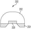
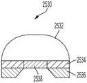
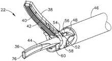
在另一方面,本公开提供了一种组合式超声/双极RF能量外科装置。该组合式超声/双极RF能量外科装置包括端部执行器。端部执行器包括夹持臂和超声刀。夹持臂包括可移动夹钳、柔性聚合物垫和至少一个双极RF电极。至少一个电极联接到RF发生器的正极,并且超声刀联接到RF发生器的负极。超声刀声学联接到由超声发生器驱动的超声换能器叠堆。在一个方面,提供了部分导电夹持臂垫,以使得电极能够磨穿并最小化超声刀与双极RF电极之间的电短路。该夹持臂垫包括导电部分和不导电部分,从而使得其充当双极RF电极中的一者,同时还充当超声刀的耐磨支撑结构。该夹持臂垫的导电部分围绕垫的周边定位并且不定位在超声刀接触区域的正下方。导电部分被配置为劣化或磨损,以防止与超声刀的任何接触中断剩余导电垫的导电性。In another aspect, the present disclosure provides a combined ultrasonic/bipolar RF energy surgical device. The combined ultrasonic/bipolar RF energy surgical device includes an end effector. The end effector includes a gripping arm and an ultrasonic blade. The clamp arm includes a movable clamp, a flexible polymer pad, and at least one bipolar RF electrode. At least one electrode is coupled to the positive electrode of the RF generator, and the ultrasonic blade is coupled to the negative electrode of the RF generator. The ultrasonic blade is acoustically coupled to a stack of ultrasonic transducers driven by an ultrasonic generator. In one aspect, a partially conductive clamp arm pad is provided to enable the electrode to wear through and to minimize electrical shorting between the ultrasonic blade and the bipolar RF electrode. The clamp arm pad includes a conductive portion and a non-conductive portion so that it acts as one of the bipolar RF electrodes while also acting as a wear-resistant support structure for the ultrasonic blade. The conductive portion of the clamp arm pad is positioned around the perimeter of the pad and is not positioned directly below the contact area of the ultrasonic blade. The conductive portion is configured to degrade or wear out to prevent any contact with the ultrasonic blade from interrupting the conductivity of the remaining conductive pads.
除上述内容之外,在诸如本公开的文本(例如,权利要求和/或具体实施方式)和/或附图的教导内容中列出和描述了各种其他方法和/或系统和/或程序产品方面。In addition to the foregoing, various other methods and/or systems and/or procedures are set forth and described in the teachings such as the text (eg, claims and/or detailed description) and/or drawings of the present disclosure. product.
上述内容是概述,因此可包括简化、概括、纳入部分和/或细节的省略;因此,本领域技术人员应当理解,该概述仅仅是说明性的,并不旨在以任何方式进行限制。本文描述的装置和/或过程和/或其他主题的其他方面、特征和优点将在本文列出的教导内容中变得显而易见。The foregoing is an overview and thus may include simplifications, generalizations, omissions of incorporated parts and/or details; therefore, those skilled in the art will understand that this summary is illustrative only and is not intended to be limiting in any way. Other aspects, features, and advantages of the apparatuses and/or processes and/or other subject matter described herein will become apparent from the teachings set forth herein.
在各方面中的一个或多个方面,相关系统包括但不限于用于执行本文引用的方法方面的电路和/或编程;电路和/或编程实际上可以是被配置为能够根据系统设计者的设计选择来影响本文引用的方法方面的硬件、软件和/或固件的任意组合。除上述内容之外,在诸如本公开的文本(例如,权利要求和/或具体实施方式)和/或附图的教导内容中列出和描述了各种其他方法和/或系统方面。In one or more of the various aspects, the relevant system includes, but is not limited to, circuitry and/or programming for performing the method aspects referenced herein; the circuitry and/or programming may actually be configured to be capable of being configured according to the system designer's Any combination of hardware, software and/or firmware design choices affect the method aspects recited herein. In addition to the foregoing, various other method and/or system aspects are set forth and described in the teachings such as the text (eg, claims and/or detailed description) and/or drawings of the present disclosure.
此外,应当理解,下述形式、形式表达、示例中的任何一个或多个可与下述其他形式、形式表达和示例中的任何一个或多个组合。Furthermore, it should be understood that any one or more of the following forms, formal expressions, examples may be combined with any one or more of the following other forms, formal expressions, and examples.
上述发明内容仅为例示性的,并非旨在以任何方式进行限制。除了上述例示性方面、实施方案和特征,参考附图和下述具体实施方式,其他方面、实施方案和特征将变得显而易见。The foregoing summary is exemplary only and is not intended to be limiting in any way. In addition to the illustrative aspects, embodiments, and features described above, other aspects, embodiments, and features will become apparent with reference to the accompanying drawings and the following detailed description.
附图说明Description of drawings
所述形式的新型特征部在随附权利要求书中具体阐述。然而,关于组织和操作方法的所述形式可通过结合附图参照以下描述最好地理解,其中:The novel features of the described form are set forth with particularity in the appended claims. However, the described forms with respect to organization and methods of operation are best understood by reference to the following description in conjunction with the accompanying drawings, wherein:
图1是根据本公开的至少一个方面的与组合式超声/RF装置一起使用的端部执行器的夹持臂部分的透视图。1 is a perspective view of a clamp arm portion of an end effector for use with a combined ultrasound/RF device in accordance with at least one aspect of the present disclosure.
图2是根据本公开的至少一个方面的图1所示的夹持臂的分解图。2 is an exploded view of the clamp arm shown in FIG. 1 in accordance with at least one aspect of the present disclosure.
图3和图4是根据本公开的至少一个方面的框架的透视图。3 and 4 are perspective views of a frame according to at least one aspect of the present disclosure.
图5是根据本公开的至少一个方面的电极的透视图。5 is a perspective view of an electrode according to at least one aspect of the present disclosure.
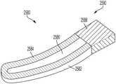
图6是根据本公开的至少一个方面的夹持臂垫的透视图。6 is a perspective view of a clamp arm pad in accordance with at least one aspect of the present disclosure.
图7是根据本公开的至少一个方面的大间隙垫的透视顶视图。7 is a perspective top view of a large gap pad in accordance with at least one aspect of the present disclosure.
图8是根据本公开的至少一个方面的小间隙垫的透视顶视图。8 is a perspective top view of a small gap pad in accordance with at least one aspect of the present disclosure.
图9是图8所示的小间隙垫的透视底视图。FIG. 9 is a perspective bottom view of the small gap pad shown in FIG. 8 .
图10至图12示出了根据本公开的各个方面的包括适于可偏转/悬臂式电极应用的缩短的夹持臂的执行器,其中:10-12 illustrate actuators including shortened gripping arms suitable for deflectable/cantilevered electrode applications in accordance with various aspects of the present disclosure, wherein:
图10是根据本公开的至少一个方面的包括缩短的夹持臂、超声刀、电极和夹持臂垫的端部执行器的侧视图;10 is a side view of an end effector including a shortened clamp arm, an ultrasonic blade, an electrode, and a clamp arm pad in accordance with at least one aspect of the present disclosure;
图11是根据本公开的至少一个方面的端部执行器的顶视图;并且11 is a top view of an end effector in accordance with at least one aspect of the present disclosure; and
图12示出了根据本公开的至少一个方面的包括夹钳、电极和夹持臂垫的夹持臂。12 illustrates a clamp arm including a clamp, an electrode, and a clamp arm pad in accordance with at least one aspect of the present disclosure.
图13示出了根据本公开的至少一个方面的包括夹钳、电极和夹持臂垫的端部执行器夹持臂。13 illustrates an end effector clamp arm including a clamp, an electrode, and a clamp arm pad in accordance with at least one aspect of the present disclosure.
图14示出了根据本公开的至少一个方面的包括夹钳、电极和夹持臂垫的端部执行器夹持臂。14 illustrates an end effector clamp arm including a clamp, an electrode, and a clamp arm pad in accordance with at least one aspect of the present disclosure.
图15示出了根据本公开的至少一个方面的包括夹钳、电极和夹持臂垫的端部执行器夹持臂。15 illustrates an end effector clamp arm including a clamp, an electrode, and a clamp arm pad in accordance with at least one aspect of the present disclosure.
图16示出了根据本公开的至少一个方面的被磨损掉的底部保持器齿,使得电极可由于预成形曲线而朝向夹钳移动。16 shows the bottom retainer teeth worn away so that the electrodes can move toward the jaws due to the pre-shaped curve, in accordance with at least one aspect of the present disclosure.
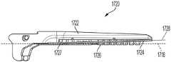
图17示出了根据本公开的至少一个方面的包括夹钳、电极和夹持臂垫的端部执行器夹持臂。17 illustrates an end effector clamp arm including a clamp, an electrode, and a clamp arm pad in accordance with at least one aspect of the present disclosure.
图18示出了根据本公开的至少一个方面的具有被磨损掉的锥形轮廓的保持器壁,使得存在足够的熔化/流动离开具有锥形轮廓区域的保持器壁,以允许电极由于预成形曲线而朝向夹钳移动。18 illustrates a retainer wall having a tapered profile that is worn away such that there is sufficient melt/flow out of the retainer wall having a tapered profile area to allow the electrode to due to pre-forming in accordance with at least one aspect of the present disclosure curve and move towards the clamp.
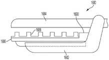
图19至图21示出了根据本公开的至少一个方面的端部执行器,该端部执行器包括夹持臂、超声刀、网格衬垫、设置在网格衬垫上方的柔性电极,以及用以设置柔性电极与超声刀之间的间隙的多个硬间隔件,其中:19-21 illustrate an end effector according to at least one aspect of the present disclosure, the end effector comprising a clamp arm, an ultrasonic blade, a mesh pad, a flexible electrode disposed over the mesh pad, and a plurality of hard spacers for setting the gap between the flexible electrode and the ultrasonic blade, wherein:
图19示出了夹持臂打开并且厚度不均匀的组织(T1a、T2a、T3a)设置在柔性电极上方;Figure 19 shows that the clamping arms are open and tissue of non-uniform thickness (T1a , T2a , T3a ) is placed over the flexible electrodes;
图20示出了夹持臂闭合以压缩组织;并且Figure 20 shows the clamping arms closed to compress the tissue; and
图21是图19至图20所示的端部执行器的分解图。Figure 21 is an exploded view of the end effector shown in Figures 19-20.
图22是根据本公开的至少一个方面的导电聚合物夹持臂垫的剖视图。22 is a cross-sectional view of a conductive polymer clamp arm pad in accordance with at least one aspect of the present disclosure.
图23是根据本公开的至少一个方面的被配置为能够取代常规电极的夹持臂垫的透视图。23 is a perspective view of a clamp arm pad configured to replace a conventional electrode, according to at least one aspect of the present disclosure.
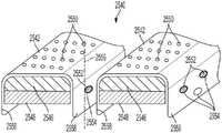
图24示出了根据本公开的至少一个方面的包括图23所述的夹持臂垫的夹持臂。24 illustrates a clamp arm including the clamp arm pad of FIG. 23 in accordance with at least one aspect of the present disclosure.
图25示出了根据本公开的至少一个方面的如图23至图24中所述构造的夹持臂垫。25 illustrates a clamp arm pad configured as described in FIGS. 23-24 in accordance with at least one aspect of the present disclosure.
图26是根据本公开的至少一个方面的包括与组织接触的复合材料夹持臂垫的夹持臂的剖视图。26 is a cross-sectional view of a clamp arm including a tissue-contacting composite clamp arm pad in accordance with at least one aspect of the present disclosure.
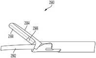
图27示出了根据本公开的至少一个方面的夹持臂,该夹持臂包括用于支撑附接到夹钳的支架或冲压件的夹钳以及夹持臂垫。27 illustrates a clamp arm including a clamp for supporting a bracket or stamping attached to the clamp and a clamp arm pad according to at least one aspect of the present disclosure.
图28是沿图27中的截面28-28截取的剖视图。FIG. 28 is a cross-sectional view taken along section 28-28 in FIG. 27 .
图29是沿图27中的截面29-29截取的剖视图。FIG. 29 is a cross-sectional view taken along section 29-29 in FIG. 27 .
图30是根据本公开的至少一个方面的包括夹钳、导电垫和不导电垫的夹持臂的另选具体实施的剖视图。30 is a cross-sectional view of an alternative implementation of a clamp arm including a clamp, a conductive pad, and a non-conductive pad in accordance with at least one aspect of the present disclosure.
图31是根据本公开的至少一个方面的包括夹钳、焊接到夹钳的支架或冲压件、导电垫和不导电垫的夹持臂的另选具体实施的剖视图。31 is a cross-sectional view of an alternative implementation of a clamp arm including a clamp, a bracket or stamping welded to the clamp, a conductive pad, and a non-conductive pad in accordance with at least one aspect of the present disclosure.
图32示出了根据本公开的至少一个方面的嵌件模制电极。32 illustrates an insert-molded electrode in accordance with at least one aspect of the present disclosure.
图33示出了根据本公开的至少一个方面的包括超声刀、夹持臂和包含导电膜的夹持臂垫的端部执行器。33 illustrates an end effector including an ultrasonic blade, a clamp arm, and a clamp arm pad including a conductive film in accordance with at least one aspect of the present disclosure.
图34示出了图33所示的夹持臂。FIG. 34 shows the clamp arm shown in FIG. 33 .
图35是沿图34中的截面35-35截取的夹持臂的剖视图。FIG. 35 is a cross-sectional view of the clamp arm taken along section 35-35 in FIG. 34 .
图36示出了根据本公开的至少一个方面的包括部分导电夹持臂垫的夹持臂。36 illustrates a clamp arm including a partially conductive clamp arm pad in accordance with at least one aspect of the present disclosure.
图37示出了根据本公开的至少一个方面的包括夹钳、夹持臂垫和绕线式电极的夹持臂。37 illustrates a clamp arm including a clamp, a clamp arm pad, and a wire-wound electrode in accordance with at least one aspect of the present disclosure.
图38示出了根据本公开的至少一个方面的包括夹钳、夹持臂垫和绕线式电极的夹持臂。38 illustrates a clamp arm including a clamp, a clamp arm pad, and a wire-wound electrode in accordance with at least one aspect of the present disclosure.
图39示出了根据本公开的至少一个方面的外科装置,该外科装置在装置上包括模式选择按钮开关。39 illustrates a surgical device including a mode selection button switch on the device according to at least one aspect of the present disclosure.
图40A至图40C示出了根据本公开的至少一个方面的用于选择外科装置的各种操作模式的三个选项,其中:40A-40C illustrate three options for selecting various modes of operation of a surgical device in accordance with at least one aspect of the present disclosure, wherein:
图40A示出了第一模式选择选项,其中可向前或向后按压按钮开关以使外科器械在各种模式之间循环;Figure 40A shows a first mode selection option in which a push button switch can be pressed forward or backward to cycle the surgical instrument between the various modes;
图40B示出了第二模式选择选项,其中向上或向下按压按钮开关以使外科器械在各种模式之间循环;并且Figure 40B shows a second mode selection option in which the push button switch is pressed up or down to cycle the surgical instrument between the various modes; and
图40C示出了第三模式选择选项,其中向前、向后、向上或向下按压按钮开关以使外科器械在各种模式之间循环。Figure 40C shows a third mode selection option, where the push button switch is pressed forward, backward, up or down to cycle the surgical instrument between the various modes.
图41示出了根据本公开的至少一个方面的外科装置,该外科装置在装置的背面上包括模式选择按钮开关。41 illustrates a surgical device including a mode selection push button switch on the back of the device in accordance with at least one aspect of the present disclosure.
图42A示出了第一模式选择选项,其中随着模式按钮开关被按下以在各种模式之间切换,有色光在用户界面上指示所选模式。FIG. 42A shows a first mode selection option in which a colored light indicates the selected mode on the user interface as the mode button switch is pressed to switch between the various modes.
图42B示出了第二模式选择选项,其中随着模式按钮开关被按下以在各种模式之间切换,屏幕指示所选模式(例如,LCD、电子墨水)。Figure 42B shows a second mode selection option where the screen indicates the selected mode (eg, LCD, e-ink) as the mode button switch is pressed to switch between the various modes.
图42C示出了第三模式选择选项,其中随着模式按钮开关被按下以在各种模式之间切换,所标记的灯指示所选模式。Figure 42C shows a third mode selection option, where as the mode button switch is pressed to switch between the various modes, the marked lights indicate the selected mode.
图42D示出了第四模式选择选项,其中随着所标记的按钮开关被按下以选择模式,当选择了所标记的按钮开关时,它被点亮以指示所选模式。Figure 42D shows a fourth mode selection option, wherein as the marked pushbutton switch is pressed to select a mode, when the marked pushbutton switch is selected, it is illuminated to indicate the selected mode.
图43示出了根据本公开的至少一个方面的包括触发器激活机构的外科装置。43 illustrates a surgical device including a trigger activation mechanism in accordance with at least one aspect of the present disclosure.
图44示出了根据本公开的至少一个方面的包括金属夹钳、电极、多个夹持臂垫以及间隙垫的另选夹持臂。44 illustrates an alternative clamp arm including a metal clamp, an electrode, a plurality of clamp arm pads, and a gap pad in accordance with at least one aspect of the present disclosure.
图45是根据本公开的至少一个方面的包括与可视化系统、机器人系统和智能器械配对的外科集线器的外科系统。45 is a surgical system including a surgical hub paired with a visualization system, a robotic system, and a smart instrument in accordance with at least one aspect of the present disclosure.
图46示出了根据本公开的至少一个方面的发生器的示例。46 shows an example of a generator in accordance with at least one aspect of the present disclosure.
图47是根据本公开的至少一个方面的能够组合以定制模块化能量系统的多种模块和其他部件的图。47 is a diagram of various modules and other components that can be combined to customize a modular energy system in accordance with at least one aspect of the present disclosure.
图48A是根据本公开的至少一个方面的第一示例性模块化能量系统配置,其包括头模块和显示屏,该显示屏呈现用于中继关于连接到头模块的模块的信息的图形用户界面(GUI)。48A is a first exemplary modular energy system configuration including a head module and a display screen presenting a graphical user interface for relaying information about modules connected to the head module in accordance with at least one aspect of the present disclosure ( GUI).
图48B是根据本公开的至少一个方面的安装到推车的图48A中所示的模块化能量系统。48B is the modular energy system shown in FIG. 48A mounted to a cart in accordance with at least one aspect of the present disclosure.
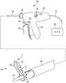
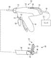
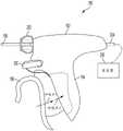
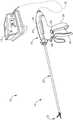
图49示出了根据本公开的至少一个方面的示例性外科系统的透视图,该系统具有发生器和能够操作以利用超声能量和双极RF能量处理组织的外科器械。49 illustrates a perspective view of an exemplary surgical system having a generator and a surgical instrument operable to treat tissue with ultrasonic energy and bipolar RF energy in accordance with at least one aspect of the present disclosure.
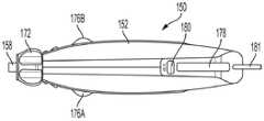
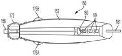
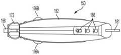
图50示出了根据本公开的至少一个方面的图49的外科器械的端部执行器的顶部透视图,该端部执行器具有提供第一电极的夹持臂和提供第二电极的超声刀。50 illustrates a top perspective view of the end effector of the surgical instrument of FIG. 49 having a gripping arm providing a first electrode and an ultrasonic blade providing a second electrode in accordance with at least one aspect of the present disclosure .
图51示出了根据本公开的至少一个方面的图50的端部执行器的底部透视图。51 illustrates a bottom perspective view of the end effector of FIG. 50 in accordance with at least one aspect of the present disclosure.
图52示出了根据本公开的至少一个方面的图49的外科器械的局部分解透视图。52 illustrates a partially exploded perspective view of the surgical instrument of FIG. 49 in accordance with at least one aspect of the present disclosure.
图53示出了根据本公开的至少一个方面的图49的外科器械的轴组件的远侧部分和端部执行器的放大分解透视图。53 shows an enlarged exploded perspective view of the distal portion and end effector of the shaft assembly of the surgical instrument of FIG. 49 in accordance with at least one aspect of the present disclosure.
具体实施方式Detailed ways
本专利申请的申请人拥有于2019年12月30日提交的以下美国临时专利申请,这些临时专利申请中的每一者的公开内容全文以引用方式并入本文:The applicant of the present patent application has the following US provisional patent applications filed on December 30, 2019, the disclosures of each of these provisional patent applications are incorporated herein by reference in their entirety:
·美国临时专利申请序列号62/955,294,名称为USER INTERFACE FOR SURGICALINSTRUMENT WITH COMBINATION ENERGY MODALITY END-EFFECTOR;U.S. Provisional Patent Application Serial No. 62/955,294, titled USER INTERFACE FOR SURGICALINSTRUMENT WITH COMBINATION ENERGY MODALITY END-EFFECTOR;
·美国临时专利申请序列号62/955,299,名称为ELECTROSURGICAL INSTRUMENTSFOR COMBINATION ENERGY DELIVERY;以及U.S. Provisional Patent Application Serial No. 62/955,299, entitled ELECTROSURGICAL INSTRUMENTSFOR COMBINATION ENERGY DELIVERY; and
·美国临时专利申请序列号62/955,306,名称为SURGICAL INSTRUMENTS。• US Provisional Patent Application Serial No. 62/955,306, entitled SURGICAL INSTRUMENTS.
本申请的申请人拥有与本申请于同一日期提交且各自全文以引用方式并入本文的以下美国专利申请:The applicant of the present application has the following US patent applications filed on the same date as the present application and each of which is incorporated herein by reference in its entirety:
·代理人案卷号END9232USNP1/190715-1,名称为USER INTERFACE FOR SURGICALINSTRUMENT WITH COMBINATION ENERGY MODALITY END-EFFECTOR;·Attorney file number END9232USNP1/190715-1, named USER INTERFACE FOR SURGICALINSTRUMENT WITH COMBINATION ENERGY MODALITY END-EFFECTOR;
·代理人案卷号END9233USNP1/190716-1M,名称为METHOD OF OPERATING ACOMBINATION ULTRASONIC/BIPOLAR RF SURGICAL DEVICE WITH A COMBINATION ENERGYMODALITY END-EFFECTOR;·Attorney file number END9233USNP1/190716-1M, named METHOD OF OPERATING ACOMBINATION ULTRASONIC/BIPOLAR RF SURGICAL DEVICE WITH A COMBINATION ENERGYMODALITY END-EFFECTOR;
·代理人案卷号END9233USNP2/190716-2,名称为DEFLECTABLE SUPPORT OF RFENERGY ELECTRODE WITH RESPECT TO OPPOSING ULTRASONIC BLADE;·Attorney's file number END9233USNP2/190716-2, named DEFLECTABLE SUPPORT OF RFENERGY ELECTRODE WITH RESPECT TO OPPOSING ULTRASONIC BLADE;
·代理人案卷号END9233USNP3/190716-3,名称为NON-BIASED DEFLECTABLEELECTRODE TO MINIMIZE CONTACT BETWEEN ULTRASONIC BLADE AND ELECTRODE;·Attorney file number END9233USNP3/190716-3, named NON-BIASED DEFLECTABLEELECTRODE TO MINIMIZE CONTACT BETWEEN ULTRASONIC BLADE AND ELECTRODE;
·代理人案卷号END9233USNP4/190716-4,名称为DEFLECTABLE ELECTRODE WITHHIGHER DISTAL BIAS RELATIVE TO PROXIMAL BIAS;·Attorney's file number END9233USNP4/190716-4, named DEFLECTABLE ELECTRODE WITHHIGHER DISTAL BIAS RELATIVE TO PROXIMAL BIAS;
·代理人案卷号END9233USNP5/190716-5,名称为DEFLECTABLE ELECTRODE WITHVARIABLE COMPRESSION BIAS ALONG THE LENGTH OF THE DEFLECTABLE ELECTRODE;·Attorney's file number END9233USNP5/190716-5, named DEFLECTABLE ELECTRODE WITHVARIABLE COMPRESSION BIAS ALONG THE LENGTH OF THE DEFLECTABLE ELECTRODE;
·代理人案卷号END9233USNP6/190716-6,名称为ASYMMETRIC SEGMENTEDULTRASONIC SUPPORT PAD FOR COOPERATIVE ENGAGEMENT WITH A MOVABLE RFELECTRODE;·Attorney's file number END9233USNP6/190716-6, named ASYMMETRIC SEGMENTEDULTRASONIC SUPPORT PAD FOR COOPERATIVE ENGAGEMENT WITH A MOVABLE RFELECTRODE;
·代理人案卷号END9233USNP7/190716-7,名称为VARIATION IN ELECTRODEPARAMETERS AND DEFLECTABLE ELECTRODE TO MODIFY ENERGY DENSITY AND TISSUEINTERACTION;·Attorney file number END9233USNP7/190716-7, named VARIATION IN ELECTRODEPARAMETERS AND DEFLECTABLE ELECTRODE TO MODIFY ENERGY DENSITY AND TISSUEINTERACTION;
·代理人案卷号END9233USNP8/190716-8,名称为TECHNIQUES FOR DETECTINGULTRASONIC BLADE TO ELECTRODE CONTACT AND REDUCING POWER TO ULTRASONIC BLADE;以及Attorney Docket No. END9233USNP8/190716-8, titled TECHNIQUES FOR DETECTINGULTRASONIC BLADE TO ELECTRODE CONTACT AND REDUCING POWER TO ULTRASONIC BLADE; and
·代理人案卷号END9233USNP9/190716-9,名称为CLAMP ARM JAW TO MINIMIZETISSUE STICKING AND IMPROVE TISSUE CONTROL。·Attorney's file number END9233USNP9/190716-9, named CLAMP ARM JAW TO MINIMIZETISSUE STICKING AND IMPROVE TISSUE CONTROL.
本申请的申请人拥有于2020年5月28日提交且各自全文以引用方式并入本文的以下美国专利申请:The applicant of the present application has the following US patent applications filed on May 28, 2020, each of which is incorporated herein by reference in its entirety:
·美国专利申请序列号16/885,813,名称为METHOD FOR AN ELECTROSURGICALPROCEDURE;U.S. Patent Application Serial No. 16/885,813, entitled METHOD FOR AN ELECTROSURGICAL PROCEDURE;
·美国专利申请序列号16/885,820,名称为ARTICULATABLE SURGICALINSTRUMENT;U.S. Patent Application Serial No. 16/885,820, titled ARTICULATABLE SURGICALINSTRUMENT;
·美国专利申请序列号16/885,823,名称为SURGICAL INSTRUMENT WITH JAWALIGNMENT FEATURES;U.S. Patent Application Serial No. 16/885,823, entitled SURGICAL INSTRUMENT WITH JAWALIGNMENT FEATURES;
·美国专利申请序列号16/885,826,名称为SURGICAL INSTRUMENT WITHROTATABLE AND ARTICULATABLE SURGICAL END EFFECTOR;U.S. Patent Application Serial No. 16/885,826 entitled SURGICAL INSTRUMENT WITHROTATABLE AND ARTICULATABLE SURGICAL END EFFECTOR;
·美国专利申请序列号16/885,838,名称为ELECTROSURGICAL INSTRUMENT WITHASYNCHRONOUS ENERGIZING ELECTRODES;U.S. Patent Application Serial No. 16/885,838, entitled ELECTROSURGICAL INSTRUMENT WITHASYNCHRONOUS ENERGIZING ELECTRODES;
·美国专利申请序列号16/885,851,名称为ELECTROSURGICAL INSTRUMENT WITHELECTRODES BIASING SUPPORT;U.S. Patent Application Serial No. 16/885,851, entitled ELECTROSURGICAL INSTRUMENT WITHELECTRODES BIASING SUPPORT;
·美国专利申请序列号16/885,860,名称为ELECTROSURGICAL INSTRUMENT WITHFLEXIBLE WIRING ASSEMBLIES;U.S. Patent Application Serial No. 16/885,860, entitled ELECTROSURGICAL INSTRUMENT WITHFLEXIBLE WIRING ASSEMBLIES;
·美国专利申请序列号16/885,866,名称为ELECTROSURGICAL INSTRUMENT WITHVARIABLE CONTROL MECHANISMS;U.S. Patent Application Serial No. 16/885,866, entitled ELECTROSURGICAL INSTRUMENT WITHVARIABLE CONTROL MECHANISMS;
·美国专利申请序列号16/885,870,名称为ELECTROSURGICAL SYSTEMS WITHINTEGRATED AND EXTERNAL POWER SOURCES;U.S. Patent Application Serial No. 16/885,870, entitled ELECTROSURGICAL SYSTEMS WITHINTEGRATED AND EXTERNAL POWER SOURCES;
·美国专利申请序列号16/885,873,名称为ELECTROSURGICAL INSTRUMENTS WITHELECTRODES HAVING ENERGY FOCUSING FEATURES;U.S. Patent Application Serial No. 16/885,873, entitled ELECTROSURGICAL INSTRUMENTS WITHELECTRODES HAVING ENERGY FOCUSING FEATURES;
·美国专利申请序列号16/885,879,名称为ELECTROSURGICAL INSTRUMENTS WITHELECTRODES HAVING VARIABLE ENERGY DENSITIES;U.S. Patent Application Serial No. 16/885,879, entitled ELECTROSURGICAL INSTRUMENTS WITHELECTRODES HAVING VARIABLE ENERGY DENSITIES;
·美国专利申请序列号16/885,881,名称为ELECTROSURGICAL INSTRUMENT WITHMONOPOLAR AND BIPOLAR ENERGY CAPABILITIES;U.S. Patent Application Serial No. 16/885,881, entitled ELECTROSURGICAL INSTRUMENT WITHMONOPOLAR AND BIPOLAR ENERGY CAPABILITIES;
·美国专利申请序列号16/885,888,名称为ELECTROSURGICAL END EFFECTORSWITH THERMALLY INSULATIVE AND THERMALLY CONDUCTIVE PORTIONS;U.S. Patent Application Serial No. 16/885,888, entitled ELECTROSURGICAL END EFFECTORSWITH THERMALLY INSULATIVE AND THERMALLY CONDUCTIVE PORTIONS;
·美国专利申请序列号16/885,893,名称为ELECTROSURGICAL INSTRUMENT WITHELECTRODES OPERABLE IN BIPOLAR AND MONOPOLAR MODES;U.S. Patent Application Serial No. 16/885,893, entitled ELECTROSURGICAL INSTRUMENT WITHELECTRODES OPERABLE IN BIPOLAR AND MONOPOLAR MODES;
·美国专利申请序列号16/885,900,名称为ELECTROSURGICAL INSTRUMENT FORDELIVERING BLENDED ENERGY MODALITIES TO TISSUE;U.S. Patent Application Serial No. 16/885,900, entitled ELECTROSURGICAL INSTRUMENT FORDELIVERING BLENDED ENERGY MODALITIES TO TISSUE;
·美国专利申请序列号16/885,917,名称为CONTROL PROGRAM ADAPTATION BASEDON DEVICE STATUS AND USER INPUT;U.S. Patent Application Serial No. 16/885,917, entitled CONTROL PROGRAM ADAPTATION BASEDON DEVICE STATUS AND USER INPUT;
·美国专利申请序列号16/885,923,名称为CONTROL PROGRAM FOR MODULARCOMBINATION ENERGY DEVICE;以及U.S. Patent Application Serial No. 16/885,923, entitled CONTROL PROGRAM FOR MODULARCOMBINATION ENERGY DEVICE; and
·美国专利申请序列号16/885,931,名称为SURGICAL SYSTEM COMMUNICATIONPATHWAYS。• US Patent Application Serial No. 16/885,931 entitled SURGICAL SYSTEM COMMUNICATIONPATHWAYS.
在详细说明外科器械的各种形式之前,应该指出的是,示例性形式的应用或使用并不局限于附图和具体实施方式中所示出的部件的构造和布置的细节。示例性形式可以单独实施,也可以与其他形式、变型和修改结合在一起实施,并可以通过多种方式实践或执行。此外,除非另外指明,否则本文所用的术语和表达是为了方便读者而对示例性形式进行描述而所选的,并非为了限制性的目的。Before describing in detail the various forms of surgical instruments, it should be noted that the application or use of the exemplary forms is not limited to the details of construction and the arrangement of components shown in the accompanying drawings and detailed description. The exemplary forms can be embodied alone or in combination with other forms, variations and modifications, and can be practiced or carried out in various ways. Furthermore, unless otherwise indicated, the terminology and expressions used herein have been chosen for the convenience of the reader to describe exemplary forms and are not for the purpose of limitation.
此外,应当理解,下述形式、形式表达、示例中的任何一个或多个可与下述其他形式、形式表达和示例中的任何一个或多个组合。Furthermore, it should be understood that any one or more of the following forms, formal expressions, examples may be combined with any one or more of the following other forms, formal expressions, and examples.
各种形式均涉及被配置用于在外科规程期间执行组织治疗、解剖、切割和/或凝固的改进的超声和/或电外科(RF)器械。在一种形式中,组合的超声和电外科器械可被配置用于开放式外科规程,但也应用于其他类型的外科规程,诸如微创腹腔镜、目视或胸腔镜规程,例如手持式或机器人辅助规程中的非侵入式内窥镜规程。通过同时地、独立地、顺序地或它们的组合选择性地应用多种能量模态来实现多功能性。例如,可通过同时地、独立地、顺序地或它们的组合选择性地使用超声和电外科能量(例如,单极或双极RF能量)来实现多功能性。Various forms involve improved ultrasonic and/or electrosurgical (RF) instruments configured to perform tissue treatment, dissection, cutting and/or coagulation during surgical procedures. In one form, a combined ultrasonic and electrosurgical instrument can be configured for open surgical procedures, but also applies to other types of surgical procedures, such as minimally invasive laparoscopic, visual or thoracoscopic procedures, such as hand-held or Non-invasive endoscopic procedures in robotic-assisted procedures. Versatility is achieved by selectively applying multiple energy modalities simultaneously, independently, sequentially, or a combination thereof. For example, versatility can be achieved through the selective use of ultrasound and electrosurgical energy (eg, monopolar or bipolar RF energy) simultaneously, independently, sequentially, or a combination thereof.
在一个方面,本公开提供了一种超声外科夹持设备,该超声外科夹持设备包括超声刀和可偏转RF电极,使得超声刀和可偏转RF电极协作以通过包括RF电极的设备的夹持机构与相关联的超声刀的协作来执行组织的密封、切割和夹持。夹持机构包括与超声刀协作以抓持其间的组织的枢转夹持臂。该夹持臂优选地具有夹持组织垫(也被称为“夹持臂垫”),该夹持组织垫具有多个轴向间隔开的夹持齿、节段、元件或单个单元,这些夹持齿、节段、元件或单个单元与端部执行器的超声刀协作以实现对组织的期望的密封和切割效果,同时有利于在外科规程期间抓持和夹持组织。In one aspect, the present disclosure provides an ultrasonic surgical gripping device that includes an ultrasonic blade and a deflectable RF electrode such that the ultrasonic blade and the deflectable RF electrode cooperate for gripping by the device including the RF electrode The cooperation of the mechanism with the associated ultrasonic blade performs the sealing, cutting and clamping of the tissue. The gripping mechanism includes a pivoting gripping arm that cooperates with the ultrasonic blade to grip tissue therebetween. The gripping arm preferably has a gripping tissue pad (also referred to as a "grip arm pad") having a plurality of axially spaced gripping teeth, segments, elements or single units, which The gripping teeth, segments, elements or individual units cooperate with the ultrasonic blade of the end effector to achieve the desired sealing and cutting effect on tissue while facilitating gripping and gripping of tissue during surgical procedures.
在一个方面,本文所述的端部执行器包括电极。在其他方面,本文所述的端部执行器包括电极的另选形式,以提供RF能量到组织的柔性联接、适应垫磨损/变薄、最小化过量热的产生(低摩擦系数、压力)、最小化火花的产生、最小化由于电短路引起的中断或它们的组合。电极在近侧端部处固定到夹钳并且在远侧端部处自由偏转。因此,在整个本公开中,电极可被称为悬臂梁电极或可偏转电极。In one aspect, the end effector described herein includes electrodes. In other aspects, the end effectors described herein include alternative forms of electrodes to provide flexible coupling of RF energy to tissue, accommodate pad wear/thinning, minimize excess heat generation (low coefficient of friction, pressure), Minimize the generation of sparks, minimize interruptions due to electrical shorts, or a combination thereof. The electrode is fixed to the clamp at the proximal end and is free to deflect at the distal end. Accordingly, throughout this disclosure, electrodes may be referred to as cantilever electrodes or deflectable electrodes.
在其他方面,本文所述的端部执行器包括夹持臂机构,该夹持臂机构被配置为能够在垫与超声刀之间施加高压力以抓持和密封组织、最大化夹持臂电极在受限或困难场景下接触组织的可能性,受限或困难场景诸如例如薄组织、处于横向张力下的组织、组织隆起/垂直张力,尤其是隆起组织远离夹持臂时。In other aspects, the end effectors described herein include a gripping arm mechanism configured to apply high pressure between the pad and the ultrasonic blade to grip and seal tissue, maximize gripping arm electrodes Possibility of contacting tissue in restricted or difficult scenarios such as eg thin tissue, tissue under lateral tension, tissue bulge/vertical tension, especially when bulging tissue is away from the gripping arm.
在其他方面,本文所述的端部执行器被配置为能够平衡电极之间的表面积/电流密度的匹配,平衡和最小化来自组织界面的热传导,诸如例如影响损伤形成和对称性、循环时间、残余热能。In other aspects, the end effectors described herein are configured to balance surface area/current density matching between electrodes, balance and minimize thermal conduction from tissue interfaces, such as, for example, affecting lesion formation and symmetry, cycle time, residual heat.
在其他方面,本文所述的端部执行器被配置为能够最小化粘连、组织粘附(最小化锚定点)并且可包括小聚酰亚胺垫。In other aspects, the end effectors described herein are configured to minimize adhesions, tissue adhesion (minimize anchor points) and may include small polyimide pads.
在各个方面,本公开提供了一种组合式超声/双极RF能量外科装置。该组合式超声/双极RF能量外科装置包括端部执行器。端部执行器包括夹持臂和超声刀。夹持臂包括可移动夹钳、柔性聚合物垫和至少一个双极RF电极。至少一个电极联接到RF发生器的正极,并且超声刀联接到RF发生器的负极。超声刀声学联接到由超声发生器驱动的超声换能器叠堆。在各个方面,端部执行器包括电极偏置机构。In various aspects, the present disclosure provides a combined ultrasound/bipolar RF energy surgical device. The combined ultrasonic/bipolar RF energy surgical device includes an end effector. The end effector includes a gripping arm and an ultrasonic blade. The clamp arm includes a movable clamp, a flexible polymer pad, and at least one bipolar RF electrode. At least one electrode is coupled to the positive electrode of the RF generator, and the ultrasonic blade is coupled to the negative electrode of the RF generator. The ultrasonic blade is acoustically coupled to a stack of ultrasonic transducers driven by an ultrasonic generator. In various aspects, the end effector includes an electrode biasing mechanism.
在一个一般性方面,本公开涉及一种使用包括超声和先进双极RF能量的组合以及位于端部执行器的至少一个钳上的可移动RF电极的外科装置的方法。可移动RF电极具有从可移动RF电极的近侧端部到远侧端部的可变偏置力。可移动RF电极被分段成分立的部分,因此可处于电连通或彼此隔离。可移动RF电极由导电或部分导电材料制成。应当理解,本公开中所述的任何端部执行器都可被配置有电极偏置机构。In one general aspect, the present disclosure relates to a method of using a surgical device that includes a combination of ultrasound and advanced bipolar RF energy and a movable RF electrode on at least one jaw of an end effector. The movable RF electrode has a variable biasing force from the proximal end to the distal end of the movable RF electrode. The movable RF electrodes are segmented into discrete parts and thus can be in electrical communication or isolated from each other. Movable RF electrodes are made of conductive or partially conductive materials. It should be understood that any end effector described in this disclosure may be configured with an electrode biasing mechanism.
在一个方面,本公开提供了一种受限电极偏置机构,以防止超声刀对电极的损坏。一般来讲,在各个方面,本公开提供了一种与超声/RF组合装置一起使用的端部执行器,其中该端部执行器包括电极。在一个方面,该组合式超声/双极RF能量外科装置包括电极偏置机构。在一个方面,该受限电极偏置机构被配置为能够防止或最小化超声刀对电极的损坏。电极在近侧端部处固定到夹钳并且在远侧端部处自由偏转。因此,在整个本公开中,电极可被称为悬臂梁电极或可偏转电极。In one aspect, the present disclosure provides a limited electrode biasing mechanism to prevent damage to electrodes by an ultrasonic blade. Generally speaking, in various aspects, the present disclosure provides an end effector for use with a combined ultrasound/RF device, wherein the end effector includes electrodes. In one aspect, the combined ultrasound/bipolar RF energy surgical device includes an electrode biasing mechanism. In one aspect, the limited electrode biasing mechanism is configured to prevent or minimize damage to the electrodes by the ultrasonic blade. The electrode is fixed to the clamp at the proximal end and is free to deflect at the distal end. Accordingly, throughout this disclosure, electrodes may be referred to as cantilever electrodes or deflectable electrodes.
在各个方面,本公开提供了一种仅在包括偏置阈值机构的一个端部处固定的电极悬臂梁。在一个方面,可偏转悬臂式电极被配置用于组合式超声/双极RF能量外科装置。In various aspects, the present disclosure provides an electrode cantilever fixed only at one end that includes a biased threshold mechanism. In one aspect, a deflectable cantilever electrode is configured for a combined ultrasound/bipolar RF energy surgical device.
在一个方面,组合式超声/RF能量外科装置包括超声刀、夹持臂和至少一个穿过超声刀的电极。在一个方面,电极被配置为相对于夹持臂是可偏转的并且包括用于在电极与超声刀之间的压缩下改变组织的机械特性的多个特征部。在另一方面,电极包括防止电极与超声刀之间意外接触的特征部,以防止或最小化超声刀对电极的损坏。In one aspect, a combined ultrasonic/RF energy surgical device includes an ultrasonic blade, a clamping arm, and at least one electrode passing through the ultrasonic blade. In one aspect, the electrode is configured to be deflectable relative to the clamp arm and includes a plurality of features for changing the mechanical properties of the tissue under compression between the electrode and the ultrasonic blade. In another aspect, the electrode includes features that prevent accidental contact between the electrode and the ultrasonic blade to prevent or minimize damage to the electrode by the ultrasonic blade.
在各个方面,电极包括附接在端部执行器的夹钳的近侧端部处的金属弹簧元件。金属弹簧元件限定用于接纳穿过其的一个或多个夹持臂垫(也被称为“组织垫”或“夹持组织垫”)的开口并且包括集成的最小间隙元件。电极的该构型提供了一种防止组织积聚在偏置机构周围的方法,组织积聚在偏置机构周围可能影响电极的性能。该构型还最小化磨损垫与偏置弹簧之间的结合,增强电极与夹持臂连接的强度,通过将聚酰亚胺垫附接到电极而最小化夹持臂垫的意外释放,以及实现电极之间的表面积/电流密度的平衡匹配。电极在近侧端部处固定到夹钳并且在远侧端部处自由偏转。因此,在整个本公开中,电极是可偏转的并且可被称为悬臂梁电极或可偏转电极。In various aspects, the electrode includes a metal spring element attached at the proximal end of the jaw of the end effector. The metal spring element defines an opening for receiving one or more clamp arm pads (also referred to as "tissue pads" or "clamp tissue pads") therethrough and includes an integrated minimum clearance element. This configuration of the electrode provides a means of preventing tissue build-up around the biasing mechanism that could affect the performance of the electrode. This configuration also minimizes binding between the wear pad and the biasing spring, enhances the strength of the electrode-to-clamp arm connection, minimizes accidental release of the clamp arm pad by attaching the polyimide pad to the electrode, and A balanced matching of surface area/current density between electrodes is achieved. The electrode is fixed to the clamp at the proximal end and is free to deflect at the distal end. Accordingly, throughout this disclosure, electrodes are deflectable and may be referred to as cantilever electrodes or deflectable electrodes.
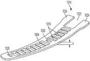
图1至图9示出了根据本公开的至少一个方面的端部执行器的一个方面,该端部执行器包括被配置用于与组合式超声/双极RF能量装置一起使用的可偏转/悬臂式电极。图1是根据本公开的至少一个方面的与组合式超声/RF装置一起使用的端部执行器的夹持臂1000部分的透视图。为了本公开的简洁和清晰,未示出用作端部执行器的另一个夹持臂的超声刀。端部执行器被配置为能够使得超声刀是双极RF电路的一个极并且夹持臂1000是相反极。夹持臂1000与超声刀之间保持一致的RF电极间隙,以防止超声刀接触电极而导致刀断裂或短路。接受治疗的组织被夹持并压缩在夹持臂1000与超声刀之间。FIGS. 1-9 illustrate an aspect of an end effector including a deflectable/bipolar RF energy device configured for use with a combined ultrasonic/bipolar RF energy device in accordance with at least one aspect of the present disclosure. Cantilever electrodes. 1 is a perspective view of a portion of a
夹持臂1000包括框架1002、电极1004、至少一个不导电小间隙垫1006、至少一个不导电大间隙垫1008、至少一个不导电夹持臂垫1010。在一个方面,小间隙垫1006和大间隙垫1008被配置为能够设定电极1004与超声刀之间的间隙。夹持臂垫1010被配置为能够抓握夹持臂1000与超声刀之间的组织以辅助组织的密封和切割。在其他方面,可交换不导电小间隙垫和不导电大间隙垫。在其他方面,不导电间隙垫简单地在尺寸方面不同,而与不导电间隙垫之间的相对尺寸差异无关。The
夹持臂1000相对于端部执行器的枢转移动通过在其近侧端部1014处提供夹持臂1000的框架1002的至少一个(优选一对)杠杆部分1012来实现。杠杆部分1012定位在超声波导和端部执行器的相应相对侧上,并且与往复致动构件的驱动部分可操作地接合。致动构件相对于外管状护套和超声波导的往复移动由此实现夹持臂1000相对于端部执行器围绕枢转点1016的枢转移动。杠杆部分1012可分别定位在由驱动部分限定的一对开口中,或以其他方式适当地与其机械地联接,由此致动构件的往复移动通过驱动部分和杠杆部分1012起作用以使夹持臂1000枢转。The pivotal movement of the
图2是根据本公开的至少一个方面的图1所示的夹持臂1000的分解图。在各个方面,电极1004由金属弹簧材料制成,该金属弹簧材料附接到夹持臂1000的框架1002的近侧端部1014处,使得电极1004可偏转。金属弹簧电极1004限定用于接纳穿过其的夹持臂垫1010的元件的开口1018,并且限定用于接纳用以设定电极1004与超声刀之间的最小间隙的间隙垫1006、1008的附加开口1020、1021。至少一个间隙垫1006设置在电极1004的远侧端部1022上。间隙垫1006、1008因此与电极1004集成。在该构型中,电极1004防止组织积聚在偏置机构(例如悬臂弹簧)周围,组织积聚在偏置机构周围可能影响电极1004的性能。该构型还最小化磨损夹持臂垫1010与偏置弹簧电极1004之间的结合,增强电极1004与夹持臂连接的强度,通过将间隙垫1006、1008附接到电极1004而最小化夹持臂垫1018的意外释放,以及实现电极之间的表面积/电流密度的平衡匹配。电极1004通过两个突出部1024附接到框架1002。如图3和图4所示,电极突出部1024附接到框架1002的近侧端部1014。FIG. 2 is an exploded view of the
图3和图4是根据本公开的至少一个方面的框架1002的透视图。这些图示出了框架1002的近侧端部1014上的连接表面1026,用于将电极1004的近侧端部附接到框架1002。在一个方面,电极突出部1024焊接到框架1002的连接表面1026,使得电极1004以可偏转方式工作。3 and 4 are perspective views of
图5是根据本公开的至少一个方面的电极1004的透视图。该图示出了由弹簧材料制成的电极1004中的偏置,如电极1004沿纵向长度的弯曲所示。开口1018、1020、1021用于接纳间隙垫1006、1008和夹持臂垫1010。在一个方面,电极1004具有0.010"的厚度“d”,并且可在例如0.005"至0.015"的厚度范围内进行选择。另外参考图8和图9,开口1020的尺寸和构造被设置成接纳限定在间隙垫1006的底部部分上的突出部1036。5 is a perspective view of
图6是根据本公开的至少一个方面的夹持臂垫1010的透视图。夹持臂垫1010包括从主干1030突出的多个夹持臂元件1032。在整个本公开中,夹持臂元件1032也被称为“齿”。在一个方面,夹持臂垫1010在间隙垫1006位于电极1004上的位置中限定孔口1028。另外参考图8和图9,由夹持臂垫1010限定的孔口1028的尺寸和构造被设置成接纳限定在间隙垫1006的底部部分上的突出部1036。在一个方面,夹持臂垫1010的材料比间隙垫1006、1008的材料软。在一个方面,夹持臂垫1010由不粘润滑材料制成,诸如聚四氟乙烯(PTFE)或类似的四氟乙烯合成含氟聚合物。PTFE是疏水的、非润湿的、高密度的和耐高温的多用途材料并且具有不粘特性。相比之下,间隙垫1006、1008由聚酰亚胺材料制成,并且在一个方面,例如由以商品名VESPEL为人所知并且由杜邦公司(DuPont)制造的耐用高性能聚酰亚胺基塑料或者其他合适的聚酰亚胺、聚酰亚胺聚合物合金、或PET(聚对苯二甲酸乙二醇酯)、PEEK(聚醚醚酮)、PEKK(聚醚酮酮)聚合物合金制成。除非下文另有说明,否则下文所述的夹持臂垫和间隙垫由本段所述的材料制成。6 is a perspective view of a
图7是根据本公开的至少一个方面的大间隙垫1008的透视顶视图。大间隙垫1008包括突出部1034,该突出部的尺寸和构造被设置成配合在电极1004的近侧端部1014处的开口1021内。图8是根据本公开的至少一个方面的小间隙垫1006的透视顶视图。图9是图8所示的小间隙垫1006的透视底视图。如图8和图9所示,小间隙垫1006包括位于底部部分处的突出部1036,该突出部的尺寸和构造被设置成接纳在由电极1004限定的开口1020和由夹持臂垫1010限定的孔口1028内。小间隙垫1006和大间隙垫1008由聚酰亚胺材料制成,并且在一个方面,由以商品名VESPEL为人所知并且由杜邦公司制造的耐用高性能聚酰亚胺基塑料制成。聚酰亚胺材料的耐久性确保电极间隙在正常磨损和撕裂下保持相对恒定。7 is a perspective top view of the
在一个方面,本公开还提供了用于组合式超声和双极RF能量装置的另外端部执行器构型。本公开的该部分提供了用于组合式超声和双极RF能量装置的端部执行器构型。在这些构型中,端部执行器在RF电极间隙与超声刀(其用作双极RF电路的一个极)以及夹持臂(其用作双极RF电路的相反极)之间保持一致的间隙。在传统的端部执行器构型中,电极间隙由柔软的PTFE夹持臂垫设定,该垫在手术过程中可能会磨损。当夹持臂垫磨穿时,超声刀可接触电极,导致刀断裂或电短路,这两者都是不期望的。In one aspect, the present disclosure also provides additional end effector configurations for combined ultrasonic and bipolar RF energy devices. This portion of the disclosure provides an end effector configuration for a combined ultrasonic and bipolar RF energy device. In these configurations, the end effector is consistent between the RF electrode gap and the ultrasonic blade (which acts as one pole of the bipolar RF circuit) and the clamp arm (which acts as the opposite pole of the bipolar RF circuit). gap. In traditional end effector configurations, the electrode gap is set by a soft PTFE clamp arm pad that can wear out during surgery. When the clamp arm pad wears through, the ultrasonic blade can contact the electrodes, resulting in blade breakage or electrical shorting, both of which are undesirable.
为了克服这些和其他限制,本公开的各方面采用可偏转RF电极与包括固定到夹持臂的不粘润滑柔性(例如,PTFE)垫的夹持臂垫的组合。RF电极包括与刀接触以设定刀-电极间隙的耐磨的不导电垫。柔性夹持臂垫延伸穿过由电极限定的开口并对来自超声刀的夹持力作出反应。随着柔性夹持臂垫磨损,电极偏转以在刀与电极之间保持恒定的间隙。这种构型在装置的整个寿命期间在电极与超声刀之间提供一致的间隙,防止当超声刀接触电极时可能发生的短路和超声刀断裂,并且使得电极材料能够直接定位在与超声刀相对的一侧上以提高密封性能。电极在近侧端部处固定到夹钳并且在远侧端部处自由偏转。因此,在整个本公开中,电极可被称为悬臂梁电极或可偏转电极。To overcome these and other limitations, aspects of the present disclosure employ a combination of deflectable RF electrodes and clamp arm pads that include a non-stick lubricated flexible (eg, PTFE) pad secured to the clamp arm. The RF electrode includes a wear-resistant, non-conductive pad in contact with the blade to set the blade-electrode gap. A flexible clamp arm pad extends through the opening defined by the electrodes and responds to clamping force from the ultrasonic blade. As the flexible clamp arm pad wears, the electrode deflects to maintain a constant gap between the blade and the electrode. This configuration provides a consistent gap between the electrode and the ultrasonic blade throughout the life of the device, prevents short circuits and fracture of the ultrasonic blade that can occur when the ultrasonic blade contacts the electrode, and enables the electrode material to be positioned directly opposite the ultrasonic blade on one side to improve sealing performance. The electrode is fixed to the clamp at the proximal end and is free to deflect at the distal end. Accordingly, throughout this disclosure, electrodes may be referred to as cantilever electrodes or deflectable electrodes.
在一个方面,本公开提供了夹持臂/电极/垫的不对称配合以实现超声刀-RF电极相互作用。在一个方面,本公开提供了一种缩短的夹持臂。图10至图12示出了根据本公开的各个方面的包括适于可偏转/悬臂式电极应用的缩短的夹持臂的执行器。在一个方面,端部执行器被配置用于夹持臂、电极和夹持臂垫的不对称配合以实现超声刀/RF电极相互作用。电极适于并被配置用于与组合式超声/双极RF能量外科装置一起使用并且能够在负载作用下偏转,其中电极是双极RF电路的一个极并且超声刀是双极RF电路的相反极。In one aspect, the present disclosure provides an asymmetrical fit of the clamp arm/electrode/pad to enable ultrasonic blade-RF electrode interaction. In one aspect, the present disclosure provides a shortened gripper arm. 10-12 illustrate an actuator including a shortened gripper arm suitable for deflectable/cantilevered electrode applications in accordance with various aspects of the present disclosure. In one aspect, the end effector is configured for asymmetrical fit of the gripper arm, electrode, and gripper arm pad to enable ultrasonic blade/RF electrode interaction. The electrodes are adapted and configured for use with a combined ultrasonic/bipolar RF energy surgical device and capable of being deflected under load, wherein the electrode is one pole of the bipolar RF circuit and the ultrasonic blade is the opposite pole of the bipolar RF circuit .
在一个方面,夹持臂的远侧端部缩短并且夹持臂垫的长度保持相同长度,使得夹持臂垫的远侧端部延伸超过夹持臂的远侧端部。这将允许电极过度延伸以最小化夹持臂的远侧端部电短路的可能性。这还可具有延长夹持臂垫寿命的有益效果,因为另外暴露的夹持臂垫材料将被磨穿。该构型还可取消使用远侧和中间间隙设置夹持臂垫,该夹持臂垫在本文中之前被称为例如可磨损夹持臂垫,用于设置和保持电极与超声刀之间的间隙。In one aspect, the distal ends of the clamp arms are shortened and the length of the clamp arm pads remain the same such that the distal ends of the clamp arm cushions extend beyond the distal ends of the clamp arms. This would allow overextending the electrodes to minimize the possibility of electrical shorting of the distal ends of the clamp arms. This may also have the beneficial effect of extending clamp arm pad life, as otherwise exposed clamp arm pad material will wear through. This configuration also eliminates the use of distal and intermediate gaps to provide clamp arm pads, formerly referred to herein as eg abradable clamp arm pads, for setting and maintaining contact between the electrodes and the ultrasonic blade. gap.
图10是根据本公开的至少一个方面的包括缩短的夹持臂1682、超声刀1684、电极1686和夹持臂垫1688的端部执行器1680的侧视图。图11是端部执行器1680的顶视图。如图10至图11所示,超声刀1684和电极1686的长度基本上相同。夹持臂1682被缩短以允许电极1686过度延伸以防止电短路。在一个方面,在端部执行器1680的近侧端部1692处提供间隙设置垫1690。10 is a side view of an
图12示出了根据本公开的至少一个方面的包括夹钳1702、电极1704和夹持臂垫1706的夹持臂1700。释放夹持臂的远侧空间。夹持臂1700被配置用于与包括如本文其他章节所公开的超声刀的端部执行器一起使用。该构型释放了夹钳1702上的远侧空间1708。夹持臂垫1706(例如,PTFE)完全支撑在下面,但t形槽区域中和侧壁上的空间被释放,以允许更多夹持臂垫1706烧穿并且电极1704进一步偏转离开超声刀(未示出)。12 shows a
在一个方面,本公开提供了一种利用垫的热行为来偏转电极的端部执行器。在一个方面,夹持臂垫的长度可与超声刀的长度相同,并且随着夹持臂垫由于压力或热而膨胀或改变形状,夹持臂垫材料(例如,PTFE)的热膨胀特性可用于使电极偏转出超声刀的路径。In one aspect, the present disclosure provides an end effector that utilizes the thermal behavior of a pad to deflect electrodes. In one aspect, the length of the gripping arm pad can be the same as the length of the ultrasonic blade, and as the gripping arm pad expands or changes shape due to pressure or heat, the thermal expansion properties of the gripping arm pad material (eg, PTFE) can be used to Deflect the electrodes out of the path of the ultrasonic blade.
在一个方面,提供了非偏置电极和垫。随着垫磨损,非偏置但可偏转的垫改变相对于夹持臂的位置。非偏置电极被配置为能够最小化超声刀与RF电极之间的接触。夹持臂垫包括用于将电极固定到夹持臂垫的特征部。在一个方面,随着夹持臂垫的高度磨损或被切穿,电极相对于夹持臂的高度以渐进方式调节。在另一方面,一旦夹持臂从超声刀移开,电极即保持在其新位置。电极在近侧端部处固定到夹持臂并且在远侧端部处自由偏转。因此,在整个本公开中,电极可被称为悬臂梁电极或可偏转电极。In one aspect, non-biased electrodes and pads are provided. As the pad wears, the non-biased but deflectable pad changes position relative to the clamp arm. The non-biased electrodes are configured to minimize contact between the ultrasonic blade and the RF electrodes. The clamp arm pad includes features for securing the electrode to the clamp arm pad. In one aspect, the electrode is adjusted in a progressive manner relative to the height of the clamp arm as the height of the clamp arm pad is worn or cut through. On the other hand, once the gripping arm is removed from the ultrasonic blade, the electrode remains in its new position. The electrode is fixed to the clamp arm at the proximal end and is free to deflect at the distal end. Accordingly, throughout this disclosure, electrodes may be referred to as cantilever electrodes or deflectable electrodes.
包括上文关于图1至图12所述的可偏转/悬臂式电极的端部执行器的构型可与如下文关于图13至图18所述的偏置电极组合。Configurations of the end effector including the deflectable/cantilevered electrodes described above with respect to Figures 1-12 may be combined with bias electrodes as described below with respect to Figures 13-18.
在一个方面,本公开提供了一种用于组合式超声/双极RF能量外科装置的端部执行器,随着夹持臂垫磨损,该端部执行器采用压力或夹钳压缩来调节电极的高度。在一个方面,夹持臂垫跟随具有可磨损止动件的夹持臂偏置电极。在一个方面,夹持臂垫包括用于将电极固定到垫的特征部。随着垫的高度磨损或被切穿,电极相对于夹持臂的高度以渐进方式调节。一旦夹持臂从超声刀移开,电极即保持在其新位置。In one aspect, the present disclosure provides an end effector for a combined ultrasonic/bipolar RF energy surgical device that employs pressure or clamp compression to adjust electrodes as clamp arm pads wear the height of. In one aspect, the clamp arm pad follows the clamp arm bias electrode with a wearable stop. In one aspect, the clamp arm pad includes features for securing the electrode to the pad. As the height of the pad is worn or cut through, the height of the electrode relative to the clamp arm is adjusted in a progressive manner. Once the gripping arm is removed from the ultrasonic blade, the electrode remains in its new position.
在组合式超声/双极RF能量外科装置上实现足够的夹持臂垫寿命需要在器械的整个寿命期间保持足够小但非零的夹持臂垫-电极间隙,以提供期望的超声和双极RF组织效应。电极适于并被配置用于与组合式超声/双极RF能量外科装置一起使用并且能够在负载作用下偏转,其中电极是双极RF电路的一个极并且超声刀是双极RF电路的相反极。Achieving adequate gripper arm pad life on a combined ultrasound/bipolar RF energy surgical device requires maintaining a sufficiently small but non-zero gripper arm pad-electrode gap throughout the life of the instrument to provide the desired ultrasound and bipolar RF tissue effect. The electrodes are adapted and configured for use with a combined ultrasonic/bipolar RF energy surgical device and capable of being deflected under load, wherein the electrode is one pole of the bipolar RF circuit and the ultrasonic blade is the opposite pole of the bipolar RF circuit .
现有(种子)电极是在自由状态(无负载)下实际上水平或平行于夹持臂的扁平电极。电极在近侧端部处固定到夹持臂并且在远侧端部处自由偏转。因此,在整个本公开中,电极可被称为悬臂梁电极或可偏转/悬臂式电极。当夹持在组织上时,组织对电极施加负载,导致使其朝向夹持臂偏转。Existing (seed) electrodes are flat electrodes that are practically horizontal or parallel to the clamp arm in the free state (no load). The electrode is fixed to the clamp arm at the proximal end and is free to deflect at the distal end. Thus, throughout this disclosure, electrodes may be referred to as cantilever electrodes or deflectable/cantilever electrodes. When clamped on tissue, the tissue applies a load to the electrode causing it to deflect toward the clamp arm.
在一个方面,随着垫磨损,电极“跟随”垫。在该方面,使用任何合适的紧固技术,诸如焊接、激光焊接、钎焊、锡焊、压制以及其他紧固技术,将电极朝向处于自由状态的夹持臂偏置(无论是通过形成/弯曲电极,还是通过不非平行于夹持臂来附接/焊接电极)。可磨损止动特征部(在垫上或其他地方)保持电极远离夹持臂,直到所述止动特征部在使用期间被磨损掉。一旦被磨损掉,电极就能够接近夹持臂。这些特征部可以是齿或棘轮形、垂直锥形或其他。In one aspect, the electrodes "follow" the pad as the pad wears. In this regard, the electrodes are biased towards the clamp arms in the free state (whether by forming/bending) using any suitable fastening technique, such as welding, laser welding, brazing, soldering, pressing and other fastening techniques electrodes, again by attaching/welding electrodes that are not non-parallel to the clamp arms). Abradable stop features (on the pad or elsewhere) keep the electrodes away from the clamp arms until the stop features are worn away during use. Once worn away, the electrode is able to access the gripping arm. These features may be toothed or ratcheted, vertically tapered, or others.
在一个方面,本公开提供了一种可偏转/悬臂式电极,其中在自由状态下,该电极被朝向夹持臂偏置并且可使用任何合适的紧固技术(诸如焊接、激光焊接、钎焊、锡焊、压制以及其他紧固技术)以一定角度附接并以制成预成形曲线。In one aspect, the present disclosure provides a deflectable/cantilevered electrode wherein, in a free state, the electrode is biased toward the clamp arm and can use any suitable fastening technique (such as welding, laser welding, brazing , soldering, pressing, and other fastening techniques) are attached at an angle and made into pre-shaped curves.
在一个方面,本公开提供了一种具有可偏转/悬臂式电极的端部执行器,该电极包括可磨损止动特征部以防止电极到达或接触夹持臂。随着止动特征部磨损,电极朝向夹持臂移动,直到其到达下一个止动件。在一个方面,止动特征部与夹持臂垫同时磨损,以保持夹持臂垫与电极之间的适当间隙。这些特征部可与夹持臂垫完全分离。这些特征部可被配置为能够承受夹持负载,但由于热(熔化/流动)或磨蚀而被磨损掉。可能的示例包括一个或多个夹持臂垫(PTFE、聚酰亚胺或其他)上的齿和一个或多个夹持臂垫(PTFE、聚酰亚胺或其他)上的锥形轮廓。In one aspect, the present disclosure provides an end effector having a deflectable/cantilevered electrode that includes a wearable stop feature to prevent the electrode from reaching or contacting a clamp arm. As the stop feature wears, the electrode moves towards the clamp arm until it reaches the next stop. In one aspect, the stop feature wears simultaneously with the clamp arm pad to maintain proper clearance between the clamp arm pad and the electrode. These features are completely separable from the clamp arm pads. These features can be configured to withstand clamping loads, but wear away due to heat (melting/flow) or abrasion. Possible examples include teeth on one or more clamp arm pads (PTFE, polyimide or other) and tapered profiles on one or more clamp arm pads (PTFE, polyimide or other).
图13示出了根据本公开的至少一个方面的包括夹钳1712、电极1714和夹持臂垫1716的端部执行器夹持臂1710。夹持臂1710被配置用于与包括如在整个本公开中所述的超声刀(未示出)的端部执行器一起使用。夹持臂1710还包括耐磨间隙垫1717,以在电极1714与超声刀之间设置间隙。如图所示,在自由状态下,电极1714以平的或水平方向1718偏置。电极1714在近侧端部处固定到夹钳1712并且在远侧端部处自由偏转。因此,在整个本公开中,电极1714可被称为悬臂梁电极或可偏转电极。13 shows an end
图14示出了根据本公开的至少一个方面的包括夹钳1722、电极1724和夹持臂垫1726的端部执行器夹持臂1720。夹持臂1720被配置用于与包括如在整个本公开中所述的超声刀(未示出)的端部执行器一起使用。夹持臂1720还包括耐磨间隙垫1727,以在电极1724与超声刀之间设置间隙。如图所示,在自由状态下,电极1724被配置成预成形的、弯曲的,或以其他方式沿线1728远离水平1718取向朝向夹钳1722偏置。电极1724在近侧端部处固定到夹持臂1720并且在远侧端部处自由偏转。因此,在整个本公开中,电极1724可被称为悬臂梁电极或可偏转电极。为了防止偏置的电极1724在偏置力的作用下朝向夹钳1722弯曲,夹持臂1720还包括保持器,以防止偏置的电极1724朝向夹钳1722弯曲并将偏置的电极1724保持在相对于超声刀呈大致平坦构型(例如,平行、平的或水平)。下面在图15至图18中描述了保持器(诸如保持器齿1738和具有锥形轮廓的保持器壁1760)的示例。14 shows an end
图15示出了根据本公开的至少一个方面的包括夹钳1732、电极1734和夹持臂垫1736的端部执行器夹持臂1730。夹持臂1730被配置用于与包括如在整个本公开中所述的超声刀(未示出)的端部执行器一起使用。夹持臂1730还包括耐磨间隙垫1737,以在电极1744与超声刀之间设置间隙。在自由状态下,电极1734被配置成预成形弯曲的、弯折的,或以其他方式朝向夹钳1732偏置。然而,在夹持臂垫1736上提供保持器齿1738或类似特征部以防止电极1734朝向夹钳1732弹入。在图16中,根据本公开的至少一个方面,当底部保持器齿1738被磨损掉时,电极1734可由于预成形曲线而朝向夹钳1732移动。电极1734在近侧端部处固定到夹持臂1730并且在远侧端部处自由偏转。因此,在整个本公开中,电极1734可被称为悬臂梁电极或可偏转电极。15 shows an end
图17示出了根据本公开的至少一个方面的包括夹钳1752、电极1754和夹持臂垫1756的端部执行器夹持臂1750。夹持臂1750被配置用于与包括如在整个本公开中所述的超声刀(未示出)的端部执行器一起使用。夹持臂1750还包括耐磨间隙垫1757,以在电极1754与超声刀之间设置间隙。在自由状态下,电极1754被配置成预成形有曲线、弯折的,或以其他方式朝向夹钳1752偏置1758。然而,在夹持臂垫1756上提供具有锥形轮廓的保持器壁1760或类似特征部以防止电极1754朝向夹钳1752弹入。17 shows an end
在图17中,根据本公开的至少一个方面,当锥形轮廓保持器壁1760被磨损掉时,存在离开锥形轮廓保持器壁1760的区域的足够的熔化/流动,以允许电极1754由于预成形曲线而朝向夹钳1752移动。电极1754在近侧端部处固定到夹钳1752并且在远侧端部处自由偏转。因此,在整个本公开中,电极1754可被称为悬臂梁电极或可偏转电极。In Figure 17, when the tapered profile holder wall 1760 is worn away, there is sufficient melt/flow out of the area of the tapered profile holder wall 1760 to allow the
在一个方面,本公开提供了一种用于组合式超声/双极RF能量外科装置的端部执行器,该端部执行器采用恒定压力分布偏置机构。在一个方面,该端部执行器包括用于安装可偏转电极和使可偏转电极绝缘的弹性可压缩支撑件。在一个方面,可采用中空的蜂窝状或带腔室的弹性体支撑附接衬垫,以允许附接到其上的电极中的全部或部分偏转但朝向超声刀偏置。该构型可提供使电极与金属夹钳的其余部分热绝缘的附加有益效果。这也将在电极周围提供弹性体“帘”以最小化电极后方的组织积聚。在一个方面,适于弹性体单元的非撑条可偏转几何形状将使得偏转力在预定偏转范围内保持恒定。电极适于并被配置用于与组合式超声/双极RF能量外科装置一起使用并且能够在负载作用下偏转,其中电极是双极RF电路的一个极并且超声刀是双极RF电路的相反极。In one aspect, the present disclosure provides an end effector for a combined ultrasonic/bipolar RF energy surgical device employing a constant pressure profile biasing mechanism. In one aspect, the end effector includes a resiliently compressible support for mounting and insulating the deflectable electrode. In one aspect, a hollow honeycomb or chambered elastomeric support attachment pad may be employed to allow all or part of the electrodes attached to it to be deflected but biased towards the ultrasonic blade. This configuration can provide the added benefit of thermally insulating the electrode from the rest of the metal clamp. This will also provide an elastomeric "curtain" around the electrode to minimize tissue buildup behind the electrode. In one aspect, a non-strut deflectable geometry suitable for the elastomeric unit will keep the deflection force constant over a predetermined deflection range. The electrodes are adapted and configured for use with a combined ultrasonic/bipolar RF energy surgical device and capable of being deflected under load, wherein the electrode is one pole of the bipolar RF circuit and the ultrasonic blade is the opposite pole of the bipolar RF circuit .
上述构型防止电极在压缩状态下横向偏斜以防止短路。此外,可偏转电极附连到弹性体并且弹性体附连到金属夹持臂。弹簧的实体高度受到驱动允许的压缩量的限制,同时保持尽可能多的金属夹持臂。来自组织界面的热传导是平衡的并且最小化-影响损伤形成和对称性、循环时间和残余热能。The above configuration prevents the electrodes from deflecting laterally in the compressed state to prevent short circuits. Furthermore, the deflectable electrode is attached to the elastomer and the elastomer is attached to the metal clamp arm. The physical height of the spring is limited by the amount of compression the drive allows, while keeping as much metal gripping arms as possible. Thermal conduction from tissue interfaces is balanced and minimized - affecting damage formation and symmetry, cycle time and residual thermal energy.
包括上文关于图1至图12所述的可偏转/悬臂式电极的端部执行器的构型可与设置在网格衬垫上方的柔性电极以及多个硬间隔件组合,以在柔性电极与超声刀之间设置间隙,如下文关于图19至图21所述。The configuration of the end effector including the deflectable/cantilevered electrodes described above with respect to FIGS. 1-12 can be combined with a flexible electrode disposed over a mesh pad and a plurality of hard spacers to A gap is provided with the ultrasonic blade, as described below with respect to FIGS. 19-21 .
如上文关于图13至图18所述的偏置电极的构型可与设置在网格衬垫上方的柔性电极以及多个硬间隔件组合,以在柔性电极与超声刀之间设置间隙,如下文关于图19至图21所述。The configuration of the bias electrode as described above with respect to Figures 13-18 can be combined with a flexible electrode disposed over a mesh pad and a plurality of hard spacers to provide a gap between the flexible electrode and the ultrasonic blade, as follows Described in relation to Figures 19-21.
包括上文关于图1至图12所述的可偏转/悬臂式电极与上文关于图13至图18所述的偏置电极的组合的端部执行器的构型可与设置在网格衬垫上方的柔性电极以及多个硬间隔件组合,以在柔性电极与超声刀之间设置间隙,如下文关于图19至图21所述。The configuration of the end effector comprising the deflectable/cantilevered electrode described above with respect to FIGS. 1-12 in combination with the biasing electrode described above with respect to FIGS. The flexible electrodes above the pads are combined with a number of hard spacers to provide a gap between the flexible electrodes and the ultrasonic blade, as described below with respect to FIGS. 19-21 .
图19至图20示出了根据本公开的至少一个方面的端部执行器1810,该端部执行器包括夹持臂1812、超声刀1814、网格衬垫1816、设置在网格衬垫1816上方的柔性电极1818,以及用以在柔性电极1818与超声刀1814之间设置间隙的多个硬间隔件1820。图21是图19至图20所示的端部执行器1810的分解图。夹持臂垫1822设置在形成于网格衬垫1816内的狭槽1825内。网格衬垫1816用作弹簧状元件。硬间隔件1820用于设置柔性电极1818与超声刀1814之间的间隙。19-20 illustrate an
在图19中,夹持臂1812是打开的并且厚度不均匀(T1a、T2a、T3a)的组织1824设置在柔性电极1818上方。在图20中,夹持臂1812闭合以压缩组织1824。夹持臂1812上的网格衬垫1816导致可变厚度组织1824(T1a、T2a、T3a)上具有一致的组织1824(T1b、T2b、T3b)压缩,使得:In FIG. 19 , the clamping

更多背景技术公开内容可见于EP3378427、WO2019/006068,这些文献全文以引用方式并入本文。Further background disclosures can be found in EP3378427, WO2019/006068, which are hereby incorporated by reference in their entirety.
在一个方面,本公开提供了一种用于组合式超声/双极RF能量外科装置的端部执行器,该端部执行器具有用于使用零间隙双极RF能量系统来确保远侧末端与偏置接触的装置。在各个方面,本公开提供了一种用于组合式超声/双极RF能量外科装置的可偏转电极,该可偏转电极具有比近侧偏置多的远侧偏置。在一个方面,本公开提供一种包括能够相对于夹持臂偏转的双极电极的组合能量装置。该组合能量装置包括改变近侧至远侧的组织压缩的机械特性的特征部,以产生比单独夹持所产生的压力模式更均匀或不同的压力模式。在一个方面,本公开提供了一种非线性远侧分布机构,并且在另一方面,本公开提供了能量密度的电非线性分布。电极适于并被配置用于与组合式超声/双极RF能量外科装置一起使用并且能够在负载作用下偏转,其中电极是双极RF电路的一个极并且超声刀是双极RF电路的相反极。In one aspect, the present disclosure provides an end effector for a combined ultrasonic/bipolar RF energy surgical device, the end effector having a device for securing a distal tip with bias using a zero-gap bipolar RF energy system. contact device. In various aspects, the present disclosure provides a deflectable electrode for a combined ultrasound/bipolar RF energy surgical device, the deflectable electrode having a more distal offset than a proximal offset. In one aspect, the present disclosure provides a combined energy device including a bipolar electrode deflectable relative to a clamp arm. The combined energy device includes features that alter the mechanical properties of tissue compression from proximal to distal to create a pressure pattern that is more uniform or different than that produced by clamping alone. In one aspect, the present disclosure provides a nonlinear distal distribution mechanism, and in another aspect, the present disclosure provides an electrically nonlinear distribution of energy density. The electrodes are adapted and configured for use with a combined ultrasonic/bipolar RF energy surgical device and capable of being deflected under load, wherein the electrode is one pole of the bipolar RF circuit and the ultrasonic blade is the opposite pole of the bipolar RF circuit .
包括上文关于图1至图12所述的可偏转/悬臂式电极的端部执行器的构型可与如下文关于图22至图36所述的导电聚合物夹持臂垫组合。Configurations of the end effector including the deflectable/cantilevered electrodes described above with respect to FIGS. 1-12 may be combined with the conductive polymer clamp arm pads described below with respect to FIGS. 22-36 .
如上文关于图13至图18所述的偏置电极的构型可与如下文关于图22至图36所述的导电聚合物夹持臂垫组合。The configuration of the bias electrode as described above with respect to FIGS. 13-18 may be combined with the conductive polymer clamp arm pads as described below with respect to FIGS. 22-36 .
设置在网格衬垫上方的柔性电极和如上文关于图19至图21所述的用以在柔性电极与超声刀之间设置间隙的多个硬间隔件的构型可与如下文关于图22至图36所述的导电聚合物夹持臂垫组合。The configuration of the flexible electrode disposed over the mesh pad and the plurality of hard spacers used to provide a gap between the flexible electrode and the ultrasonic blade as described above with respect to FIGS. Conductive polymer clamp arm pad assembly as described in Figure 36.
如上文关于图13至图18所述的偏置电极的构型可与设置在网格衬垫上方的柔性电极组合,并且如上文关于图19至图21所述的用以在柔性电极与超声刀之间设置间隙的多个硬间隔件可与如下文关于图22至图36所述的导电聚合物夹持臂垫组合。The configuration of the bias electrode as described above with respect to Figures 13-18 may be combined with a flexible electrode disposed over a mesh pad, and used as described above with respect to Figures 19-21 to be used between flexible electrodes and ultrasound A plurality of hard spacers that provide a gap between the knives can be combined with conductive polymer clamp arm pads as described below with respect to FIGS. 22-36 .
如上文关于图13至图18所述的偏置电极的构型可与设置在网格衬垫上方的柔性电极组合,并且如上文关于图19至图21所述的用以在柔性电极与超声刀之间设置间隙的多个硬间隔件可与如下文关于图22至图36所述的导电聚合物夹持臂垫组合。The configuration of the bias electrode as described above with respect to Figures 13-18 may be combined with a flexible electrode disposed over a mesh pad, and used as described above with respect to Figures 19-21 to be used between flexible electrodes and ultrasound A plurality of hard spacers that provide a gap between the knives can be combined with conductive polymer clamp arm pads as described below with respect to FIGS. 22-36 .
包括上文关于图1至图12所述的可偏转/悬臂式电极与上文关于图13至18所述的偏置电极的组合的端部执行器的构型可与下文关于图22至图36所述的导电聚合物夹持臂垫组合。The configuration of an end effector including a combination of the deflectable/cantilevered electrodes described above with respect to FIGS. 1-12 and the biasing electrodes described above with respect to FIGS. 13-18 may be discussed with respect to FIGS. The conductive polymer gripping arm pad combination of 36.
包括上文关于图1至图12所述的可偏转/悬臂式电极与上文关于图13至图18所述的偏置电极的组合的端部执行器的构型可与设置在网格衬垫上方的柔性电极组合,并且如上文关于图19至图21所述的用以在柔性电极与超声刀之间设置间隙的多个硬间隔件可与如下文关于图22至图36所述的导电聚合物夹持臂垫组合。The configuration of the end effector comprising the deflectable/cantilevered electrode described above with respect to FIGS. 1-12 in combination with the biasing electrode described above with respect to FIGS. The combination of the flexible electrodes over the pads and the plurality of hard spacers used to provide a gap between the flexible electrodes and the ultrasonic blade as described above with respect to FIGS. Conductive polymer gripping arm pad combination.
在各个方面,本公开提供了一种组合式超声/双极RF能量外科装置,该外科装置包括具有部分导电部分或全部导电部分的超声垫,使得超声垫用作刀支撑件/磨损垫和双极RF电极两者。在一个方面,本公开提供了一种部分导电的夹持臂垫以能够磨损电极并最小化组合双极RF和超声能量装置中的短路,其中夹持臂垫具有导电部分和不导电部分,从而允许其用作RF电极中的一个电极,同时还用作超声刀的可磨损支撑结构。在另一方面,本公开提供了围绕夹持臂垫的周边并且不直接定位在与超声刀接触区域相对的侧上的导电部分。在另一方面,导电夹持臂垫的一部分是可降解的或可磨损的,以防止来自超声刀的接触中断导电夹持臂垫的其余部分的导电性。In various aspects, the present disclosure provides a combined ultrasonic/bipolar RF energy surgical device that includes an ultrasonic pad having a partially or fully conductive portion such that the ultrasonic pad acts as a blade support/wear pad and a dual Both polar RF electrodes. In one aspect, the present disclosure provides a partially conductive clamp arm pad to enable electrode wear and minimize shorting in a combined bipolar RF and ultrasonic energy device, wherein the clamp arm pad has a conductive portion and a non-conductive portion, thereby This allows it to be used as one of the RF electrodes while also serving as an abradable support structure for the ultrasonic blade. In another aspect, the present disclosure provides a conductive portion that surrounds the perimeter of the clamp arm pad and is not positioned directly on the side opposite the ultrasonic blade contact area. In another aspect, a portion of the conductive clamp arm pad is degradable or abradable to prevent contact from the ultrasonic blade from interrupting the electrical conductivity of the remainder of the conductive clamp arm pad.
在一个方面,本公开提供了一种用于组合式超声/双极RF能量外科装置的端部执行器,该端部执行器包括导电聚合物超声夹持臂垫。在一个方面,端部执行器包括掺杂有氧化锡的夹持臂垫。图22是根据本公开的至少一个方面的导电聚合物夹持臂垫2440的剖视图。导电聚合物夹持臂垫2440包括嵌入聚合物材料2444诸如聚四氟乙烯(PTFE)中的氧化锡2442(SnO2),以使夹持臂垫2440导电。可使用冷喷涂工艺实现掺杂。一旦掺杂,导电聚合物夹持臂垫2440就可实现传统的超声组织夹持臂垫功能,诸如例如接触超声刀、吸收来自超声刀的热量以及辅助组织抓持和夹持。掺杂氧化锡的夹持臂垫2440用作双极RF电路的两个电极或极中的一个,以将RF能量递送到被抓持在超声刀与夹持臂垫2440之间的组织。掺杂氧化锡的夹持臂垫2440是生物相容的、导电的、导热的,使得夹持臂垫2440的大部分能够用于提高夹持臂垫2440的耐磨性,并且是白色的。电极适于并被配置用于与组合式超声/双极RF能量外科装置一起使用并且能够在负载作用下偏转,其中电极是双极RF电路的一个极并且超声刀是双极RF电路的相反极。In one aspect, the present disclosure provides an end effector for a combined ultrasonic/bipolar RF energy surgical device, the end effector including a conductive polymer ultrasonic clamp arm pad. In one aspect, the end effector includes a clamp arm pad doped with tin oxide. 22 is a cross-sectional view of a conductive polymer
在一个方面,本公开提供了一种作为电极替代物的导电聚合物超声夹持臂垫。为了延长超声夹持臂垫的寿命并提高RF组织效应,本公开提供了一种改进的、更易于制造的且制造成本更低的电极。在一个方面,本公开提供了一种包括硬聚酰亚胺聚合物层和导电层的夹持臂垫,以允许夹持臂垫实现传统功能并承载双极电,从而组合能量端部执行器的夹持臂中不再需要单独的电极。这样,夹钳可以类似于纯超声夹钳的方式制造,其中新的夹持臂垫材料与传统的纯超声夹持臂垫互换。电极适于并被配置用于与组合式超声/双极RF能量外科装置一起使用并且能够在负载作用下偏转,其中电极是双极RF电路的一个极并且超声刀是双极RF电路的相反极。In one aspect, the present disclosure provides a conductive polymer ultrasonic clamp arm pad as an electrode replacement. In order to prolong the life of the ultrasonic clamp arm pad and improve the RF tissue effect, the present disclosure provides an improved electrode that is easier to manufacture and less expensive to manufacture. In one aspect, the present disclosure provides a clamp arm pad including a hard polyimide polymer layer and a conductive layer to allow the clamp arm pad to perform conventional functions and carry bipolar electricity to combine energy end effectors A separate electrode is no longer required in the gripper arm. In this way, the clamp can be manufactured in a manner similar to a pure ultrasonic clamp, where the new clamp arm pad material is interchanged with the traditional pure ultrasonic clamp arm pad. The electrodes are adapted and configured for use with a combined ultrasonic/bipolar RF energy surgical device and capable of being deflected under load, wherein the electrode is one pole of the bipolar RF circuit and the ultrasonic blade is the opposite pole of the bipolar RF circuit .
有益效果包括改进的超声性能,包括夹持臂垫磨损、类似于当前的纯超声器械,因为聚合物的元件“正方形”之间没有电极间隙。由于不需要单独的电极部件并且提供多个小的聚合物正方形元件,因此改进的夹钳的成本将类似于当前的纯超声夹钳。此外,制造夹钳所需的制造步骤与制造当前的纯超声夹钳所需的制造步骤相同。制造该改进的夹钳只需要替换夹持臂垫并且确实需要生产附加的电极部件来添加到夹钳以及消除了组装步骤。Benefits include improved ultrasonic performance, including grip arm pad wear, similar to current pure ultrasonic instruments, as there is no electrode gap between the "squares" of polymer elements. Since no separate electrode components are required and multiple small polymer square elements are provided, the cost of the improved clamp will be similar to current pure ultrasonic clamps. Furthermore, the manufacturing steps required to manufacture the clamp are the same as those required to manufacture the current pure ultrasonic clamp. Manufacturing the improved clamp requires only replacement of the clamp arm pads and does require the production of additional electrode components to add to the clamp and eliminate assembly steps.
图23是根据本公开的至少一个方面的被配置为能够取代常规电极的夹持臂垫2450的透视图。夹持臂垫2450包括夹层状构型的不导电层2452和导电层2454。该构型消除了对弹簧加载式电极板的需要。不导电层2452可由聚合物、聚酰亚胺、聚四氟乙烯(PTFE)和类似的不导电材料制成。导电层2454可由薄导电聚合物、金属箔或碳负载材料制成。夹持臂垫2450可被制造成使得接触超声刀的材料中的大部分是不导电层2452。在一个方面,接触超声刀的材料中的75%是不导电材料,诸如PTFE。在另一方面,接触超声刀的材料中的85%是不导电材料,诸如PTFE。在另一方面,接触超声刀的材料中的95%是不导电材料,诸如PTFE。另外,随着夹持臂垫2450磨损,导电层2452仍将具有用以通过组织和返回电极(例如,超声刀)传导RF电力的可用表面积。23 is a perspective view of a
图24示出了根据本公开的至少一个方面的包括图23所述的夹持臂垫2450的夹持臂2460。在所示的夹持臂2460中,与呈现为薄层或箔的导电层2454相比,不导电层2452具有大表面积。24 illustrates a
图25示出了根据本公开的至少一个方面的如图23至图24中所述构造的夹持臂垫。第一夹持臂垫2470是新的并且包括与其一体形成的齿2472。第二夹持臂垫2476是新的但没有齿。第三夹持臂垫2478磨损并且可代表第一夹持臂垫2470或第二夹持臂垫2476。25 illustrates a clamp arm pad configured as described in FIGS. 23-24 in accordance with at least one aspect of the present disclosure. The first
在一个方面,本公开提供了一种用于组合式超声/双极RF能量外科装置的复合材料夹持臂垫。图26是根据本公开的至少一个方面的包括与组织2484接触的复合材料夹持臂垫2482的夹持臂2480的剖视图。端部执行器2480包括上夹钳2486和用以将复合材料夹持臂垫2482固定地附接到上夹钳2486的粘合剂2488。复合材料夹持臂垫2482包括薄的不导电层2490(例如,PTFE)和薄的导电层2492(例如,薄的不锈钢箔)。导电层2492形成复合材料夹持臂垫2482的电极部分。随着不导电层2490(例如,PTFE)被磨损掉,导电层2492(例如,薄的不锈钢箔)变形。导电层2492的厚度使得复合材料夹持臂垫2482的电极部分能够随着不导电层2490被磨损掉而变形。有利地,导电层2492将一些热量传导离开不导电层2490以保持复合材料夹持臂垫2482较冷。如上所述,复合材料夹持臂垫2482通过粘合剂2488固定到上夹钳2486。粘合剂2488可填充有碳以使其导电并将复合材料夹持臂垫2482的电极部分连接到上夹钳2486。电极适于并被配置用于与组合式超声/双极RF能量外科装置一起使用并且能够在负载作用下偏转,其中电极是双极RF电路的一个极并且超声刀是双极RF电路的相反极。In one aspect, the present disclosure provides a composite gripping arm pad for a combined ultrasonic/bipolar RF energy surgical device. 26 is a cross-sectional view of a
在一个方面,夹持臂垫包括协作的导电部分和绝缘部分。在一个方面,本公开提供了一种组合式超声/双极RF能量外科装置,其中夹持臂垫具有导电部分和不导电部分,允许其用作RF电极中的一个电极,同时还用作超声刀的可磨损支撑结构。在另一方面,夹持臂垫的导电部分围绕垫的周边设置并且不直接定位在与超声刀接触区域相对的侧上。在另一方面,夹持臂垫的导电部分是可降解的或可磨损的,以防止与超声刀的接触中断导电夹持臂垫的其余导电部分的导电性。In one aspect, the clamp arm pad includes cooperating conductive and insulating portions. In one aspect, the present disclosure provides a combined ultrasound/bipolar RF energy surgical device in which the clamp arm pad has a conductive portion and a non-conductive portion, allowing it to function as one of the RF electrodes while also functioning as an ultrasound Wearable support structure for knives. In another aspect, the conductive portion of the clamp arm pad is disposed around the perimeter of the pad and is not positioned directly on the side opposite the ultrasonic blade contact area. In another aspect, the conductive portion of the clamp arm pad is degradable or abradable to prevent contact with the ultrasonic blade from interrupting the conductivity of the remaining conductive portion of the conductive clamp arm pad.
在一个方面,本公开提供了一种与组合式超声/双极RF能量装置一起使用的夹持臂垫,其中夹持臂垫的一部分包括导电材料,而其他部分包括不导电材料。电极适于并被配置用于与组合式超声/RF能量装置一起使用并且能够在负载作用下偏转,其中电极是双极RF电路的一个极并且超声刀是双极RF电路的相反极。In one aspect, the present disclosure provides a clamp arm pad for use with a combined ultrasonic/bipolar RF energy device, wherein a portion of the clamp arm pad includes a conductive material and other portions include a non-conductive material. The electrodes are adapted and configured for use with a combined ultrasound/RF energy device and deflectable under load, wherein the electrode is one pole of the bipolar RF circuit and the ultrasonic blade is the opposite pole of the bipolar RF circuit.
在各个方面,可使用各种技术来制造夹持臂垫。一种技术包括在同一压模中模制导电材料和不导电材料的二次注塑工艺。该工艺有效地形成具有可用作双极RF电极的一部分和将用作电绝缘体的其他部分的单个夹持臂垫。另一种技术包括将金属元素超声冷喷涂嵌入聚合物(例如,聚四氟乙烯、PTFE)垫或基质中。另一种技术包括多种材料(例如,聚四氟乙烯、PTFE和掺杂型导电聚合物)的3D打印,将导电油墨或功能油墨打印/转印到夹持臂垫上。另一种技术包括使用化学气相沉积、物理气相沉积、溅射沉积、真空沉积、真空金属化或热喷涂将金属和导电材料(例如,石墨/碳)施加到夹持臂垫。另一种技术包括导电/负载的夹持臂垫电极通过具有微观无规取向和定位的粒子或宏观取向的结构(例如,织物、编织、长度受限纤维)的垫提供连续性。另一种技术包括使夹持臂垫的表面导电、提供磨穿式电极、3D打印、热喷涂、冷喷涂、涂层/油漆/环氧树脂、薄片/箔/线/膜缠绕或层压、真空金属化、打印/转移等技术。在另一种技术中,聚合物电极填充有导电材料。In various aspects, various techniques can be used to manufacture the clamp arm pads. One technique involves an overmolding process in which conductive and non-conductive materials are molded in the same die. This process effectively forms a single clamp arm pad with a portion that can be used as a bipolar RF electrode and the other portion that will serve as an electrical insulator. Another technique involves ultrasonic cold spray embedding of metallic elements into a polymer (eg, Teflon, PTFE) pad or matrix. Another technique involves 3D printing of multiple materials (eg, Teflon, PTFE, and doped conductive polymers) to print/transfer conductive inks or functional inks onto the gripper arm pads. Another technique includes applying metals and conductive materials (eg, graphite/carbon) to the clamp arm pads using chemical vapor deposition, physical vapor deposition, sputter deposition, vacuum deposition, vacuum metallization, or thermal spraying. Another technique includes conductive/loaded clamp arm pad electrodes providing continuity through a pad with microscopically randomly oriented and positioned particles or macroscopically oriented structures (eg, fabrics, braids, length-constrained fibers). Another technique includes making the surface of the clamp arm pad conductive, providing wear-through electrodes, 3D printing, thermal spray, cold spray, coating/paint/epoxy, foil/foil/wire/film winding or lamination, Technologies such as vacuum metallization, printing/transfer, etc. In another technique, polymer electrodes are filled with conductive material.
在一个方面,端部执行器夹持臂包括固定的聚合物电极。图27示出了根据本公开的至少一个方面的夹持臂2500,该夹持臂包括用于支撑附接到夹钳2502的支架2504或冲压件的夹钳2502以及夹持臂垫2506。夹持臂垫2506包括导电垫2508和不导电垫2510。导电垫2508由导电聚合物制成并且用作双极RF电路的电极中的一个电极。夹钳2502和支架2504可由不锈钢制成并且使用任何合适的紧固技术附接,诸如例如焊接、激光焊接、钎焊、锡焊、压制以及其他紧固技术。导电垫2508可包括聚合物,诸如例如硅树脂、氟硅树脂、PTFE和类似材料。使用PTFE、硅树脂、填充有银颗粒的氟硅树脂、覆银铝、覆银铜、铜、镍,石墨、碳(无定形,短切纤维)、金、铂、不锈钢、铁或锌或它们的组合将导电垫2508包覆模制到支架2504上。In one aspect, the end effector gripper arm includes a fixed polymer electrode. 27 illustrates a
图28是沿图27中的截面28-28截取的剖视图,并且图29是沿图27中的截面29-29截取的剖视图。剖视图28-28和29-29示出了包括夹钳2502、支撑支架2504、导电垫2508和不导电垫2510的夹持臂2500。28 is a cross-sectional view taken along section 28-28 in FIG. 27, and FIG. 29 is a cross-sectional view taken along section 29-29 in FIG. 27. FIG. Sectional views 28-28 and 29-29
图30是根据本公开的至少一个方面的包括夹钳2522、导电垫2524和不导电垫2526的夹持臂2520的另选具体实施的剖视图。导电垫2524由导电聚合物制成并且用作双极RF电路的电极中的一个电极。30 is a cross-sectional view of an alternative implementation of a
图31是根据本公开的至少一个方面的包括夹钳2532、焊接到夹钳2532的支架2534或冲压件、导电垫2536和不导电垫2538的夹持臂2530的另选具体实施的剖视图。导电垫2536由导电聚合物制成并且用作双极RF电路的电极中的一个电极。导电垫2536包覆模制或冲压到支架2534上。31 is a cross-sectional view of an alternative implementation of a
在一个方面,端部执行器夹持臂包括膜覆金属嵌件模制电极组件。在一个方面,可在金属(例如不锈钢)嵌件模制电极组件上提供膜。膜覆金属诸如不锈钢可以嵌件模制方式形成电极组件。嵌件模制电极上的膜可被蚀刻以形成微孔、狭缝、蜂窝以及其他图案,以能够传导RF能量以及切割部件的外围。可使用下文所述的IML/FIM(模内贴标/膜嵌件模制)工艺将膜形成于或结合在不锈钢电极上。可将带电膜电极放置在聚合物注塑模具中,以将聚合物模制到电极和膜的背面。电极适于并被配置用于与组合式超声/双极RF能量外科装置一起使用并且能够在负载作用下偏转,其中电极是双极RF电路的一个极并且超声刀是双极RF电路的相反极。In one aspect, the end effector clamp arm includes a film-on-metal insert molded electrode assembly. In one aspect, the membrane can be provided on a metal (eg, stainless steel) insert-molded electrode assembly. A film-coated metal such as stainless steel can be insert-molded to form the electrode assembly. The membrane on the insert-molded electrode can be etched to form pores, slits, honeycombs, and other patterns to be able to conduct RF energy and cut the periphery of the part. Films can be formed on or bonded to stainless steel electrodes using the IML/FIM (In-Mold Labeling/Film Insert Molding) process described below. The charged membrane electrode can be placed in a polymer injection mold to mold the polymer to the backside of the electrode and membrane. The electrodes are adapted and configured for use with a combined ultrasonic/bipolar RF energy surgical device and capable of being deflected under load, wherein the electrode is one pole of the bipolar RF circuit and the ultrasonic blade is the opposite pole of the bipolar RF circuit .
图32示出了根据本公开的至少一个方面的嵌件模制电极2540。嵌件模制电极2540包括导电元件2546、模制聚合物垫2548和膜2542涂层。诸如微孔、狭缝、蜂窝或类似特征部的特征部2550形成于膜2542中以允许RF能量通过。保持特征部2552也形成于膜2542上。膜2542的在聚合物垫2548的底部下方延伸的侧壁2558可围绕聚合物垫2548的底部折叠并与保持柱包覆模制。保持特征部2552被模制到由膜2542限定的孔2554中。尽管示出的两个嵌件模制电极2540之间具有间隙,但实际上,两个嵌件模制电极2540经由模制压力线对线2556配合。32 illustrates an insert-molded
导电元件2546可由诸如不锈钢或类似导电材料的导电金属制成。导电元件2546可为约0.010"厚,并且可在0.005"至0.015"的厚度范围内选择,并且可通过夯实或机加工形成。膜2544可为约0.001"至0.002"厚,并且可由聚酰亚胺、聚酯或类似材料制成。作为诸如柱的机械保持的替代,膜2544可直接结合到导电元件2546。一个示例包括厚度为0.002"的具有环氧粘合剂背衬的杜邦Pyralux HXC Kapton膜。
有利地,不粘表面防止组织粘连到嵌件模制电极2540。通过沿嵌件模制电极2540的整个长度设置在0.002"至0.004"范围内的间隙,不粘表面避免了相反电极的短路。由于嵌件模制电极2540的侧壁2558的覆盖,不粘表面使RF能量的横向传播最小化。此外,嵌件模制电极2540表现出结构牢固性并且提供比多层柔性电路更容易更稳健的电连接。Advantageously, the non-stick surface prevents tissue from adhering to the insert-molded
在一个方面,端部执行器包括用于组合式超声/双极RF能量外科装置的导电夹持臂和垫构造。在一个方面,本公开提供了一种包括导电或选择性导电薄膜、箔或层压件的夹持臂组件,这些导电或选择性导电薄膜、箔或层压件被施加到夹持臂组件、围绕夹持臂组件或在夹持臂组件上,以用作组合式超声/双极RF能量外科装置中的耐用“极”。此外,提供了算法、软件或逻辑来管理电短路的条件。电极适于并被配置用于与组合式超声/双极RF能量外科装置一起使用并且能够在负载作用下偏转,其中电极是双极RF电路的一个极并且超声刀是双极RF电路的相反极。In one aspect, the end effector includes a conductive gripping arm and pad configuration for a combined ultrasonic/bipolar RF energy surgical device. In one aspect, the present disclosure provides a clamp arm assembly comprising a conductive or selectively conductive film, foil or laminate applied to the clamp arm assembly, Around or on the clamp arm assembly for use as a durable "pole" in a combined ultrasonic/bipolar RF energy surgical device. Additionally, algorithms, software or logic are provided to manage the conditions of electrical shorts. The electrodes are adapted and configured for use with a combined ultrasonic/bipolar RF energy surgical device and capable of being deflected under load, wherein the electrode is one pole of the bipolar RF circuit and the ultrasonic blade is the opposite pole of the bipolar RF circuit .
图33示出了根据本公开的至少一个方面的包括超声刀2562、夹持臂2564和包含导电膜2568的夹持臂垫2566的端部执行器2560。33 shows an
图34示出了图33所示的夹持臂2564。夹持臂2564包括夹钳2570以支撑夹持臂垫2566。薄导电膜2568设置在夹持臂垫2566上,以形成双极RF电路的极中的一个极的电极。FIG. 34 shows the
图35是沿图34中的截面35-35-91截取的夹持臂2564的剖视图。夹钳2570可由金属诸如不锈钢制成。夹持臂垫2566可由不导电柔性材料诸如PTFE、硅树脂、高温聚合物或类似材料制成。导电膜2568或箔可由导电材料诸如钛、银、金、铝、锌及其任何合金(包括不锈钢)制成。FIG. 35 is a cross-sectional view of
图36示出了根据本公开的至少一个方面的包括部分导电夹持臂垫2582的夹持臂2580。导电箔2584覆盖不导电垫2586的一部分。近侧端部2590处的不导电垫2588在夹持臂垫2582与超声刀之间设置间隙。36 illustrates a
导电膜2568、箔或层压件的元件可包括例如单层薄导电材料,诸如金属(钛、银、金、锌、铝、镁、铁等及其合金或不锈钢)、镀覆金属(例如,铜上先镀镍,然后镀金)或大量填充有导电材料诸如金属粉末或填料的聚合物。优选地,其为具有选自0.001"至0.008"(0.025mm至0.20mm)范围内的厚度的生物相容的金属箔,诸如钛、银、金、锌或不锈钢。Elements of the
膜2568、箔或层压件可包括覆盖上述薄导电材料的薄聚合物涂层、膜或层。这种涂层、膜或层是高电阻性的,即,它不是双极RF能量到相邻组织的有效导体。涂层可被穿孔以允许能量从电极递送到组织。The
导电材料可被穿孔或包括穿过导电材料的全厚度的孔或窗,以最小化该层的热容(测试已表明,长的和/或厚的箔由于从治疗视线中去除热能而导致更长的横切时间)。这些穿孔、孔或窗还可允许将箔保持到其他部分或层。这些穿孔、孔或窗可在整个箔片材上形成图案,或可定位在治疗部位处或远离治疗部位,诸如例如仅在夹持臂的侧面上。The conductive material can be perforated or include holes or windows through the full thickness of the conductive material to minimize the thermal capacity of the layer (tests have shown that long and/or thick foils lead to more long cross-cutting time). These perforations, holes or windows may also allow the foil to be retained to other parts or layers. These perforations, holes or windows can be patterned throughout the foil, or can be positioned at the treatment site or away from the treatment site, such as for example only on the sides of the gripping arms.
如果存在,则薄聚合物涂层、膜或层可被穿孔或包括全厚度的孔或窗,使得导电膜、箔或层压件与组织直接连通,用于将双极射频能量递送到组织。对于涂层,这些孔或窗可通过选择性涂覆或涂层去除来形成。If present, the thin polymer coating, film or layer can be perforated or include full thickness holes or windows, allowing the conductive film, foil or laminate to communicate directly with the tissue for delivery of bipolar radio frequency energy to the tissue. For coatings, these holes or windows can be formed by selective coating or coating removal.
理想的是,导电膜2568、箔或层压件与通常由不锈钢制造的夹持臂结构直接接触。所得的导电路径于是实现构造的简单性,因为路径由必要的结构部件形成,即直接连接到夹持臂并且然后连接到导电膜、箔或层压件的支撑管或致动器。Ideally, the
在一个方面,导电膜2568、箔或层压件由相对柔软、高温、低磨损的聚合物或弹性体垫支撑,该垫由诸如PTFE、硅树脂、聚酰亚胺、高温热塑性塑料以及其他材料制成。该相对柔软的垫的顺应性允许宽范围的部件公差,以在夹钳完全闭合时沿其整个组织作用长度在夹钳与超声刀之间获得零或接近零的间隙,从而能够沿该长度密封和切割组织。顺应性还消除或大大衰减了当超声刀靠近导电层时可能发生的导电层的任何可听见的振动。In one aspect, the
导电膜2568、箔或层压件可在其背侧/背部表面(即远离组织并朝向夹持臂的表面)上包括刚性至半刚性聚合物。该部件由能够注塑模制的聚合物或聚合物合金制成,并且通过膜嵌件模制(FIM)或模内贴标(IML)粘附到膜、箔或层压件。The
在测试中,薄的不锈钢、铜或铝箔在操作中是安静的(没有“尖叫”或发出钝尖叫声)。薄的不锈钢、铜或铝箔提供了超声刀可作用的坚固表面。足够结实,使得原本会撕裂并用作差的垫材料的材料诸如硅橡胶是可用的并且不容易撕裂或裂开。In testing, the thin stainless steel, copper, or aluminum foil was quiet in operation (no "squeaks" or dull squeaks). Thin stainless steel, copper or aluminum foil provides a solid surface on which the ultrasonic knife can act. Strong enough that materials such as silicone rubber that would otherwise tear and serve as poor pad materials are usable and do not easily tear or split.
钳夹持表面的近侧部分可不包括导电膜、箔或层压件,因为钳的该区域首先接触刀并且更可能导致该区域中出现功率分流/短路。The proximal portion of the forceps gripping surface may not include conductive films, foils or laminates, as this area of the forceps contacts the blade first and is more likely to cause power shunting/shorting in this area.
在一个方面,本公开提供了一种用于激活包括双极RF能量的输出的短路减轻算法。In one aspect, the present disclosure provides a short-circuit mitigation algorithm for activating an output comprising bipolar RF energy.
在短路发生在以下情况之后不向用户给出短路警报:为了激活而递送的能量超过阈值量(由此指示组织变薄但可能已接收到用于组织的密封、凝固的双极RF能量的足够剂量),或已超过激活时间阈值(再次,由此指示组织变薄但可能已接收到足够剂量),或已超过能量阈值和激活时间阈值两者。A short circuit alert is not given to the user after a short circuit occurs when the energy delivered for activation exceeds a threshold amount (thus indicating tissue thinning but sufficient bipolar RF energy may have been received for sealing, coagulation of the tissue) dose), or an activation time threshold has been exceeded (again, thereby indicating tissue thinning but sufficient dose may have been received), or both an energy threshold and an activation time threshold have been exceeded.
制备膜覆不锈钢嵌件模制电极组件的工艺包括:蚀刻膜并形成用于传递RF能量的孔(微孔、狭槽或蜂窝);切割电极部件的周边;如果需要,在不锈钢电极上形成膜/在将膜结合到不锈钢电极上;将带电膜和电极放置在聚合物注塑模具中;将聚合物模制到电极和膜的背面。The process of making a membrane-coated stainless steel insert-molded electrode assembly includes: etching the membrane and forming pores (micropores, slots, or honeycombs) for transmitting RF energy; cutting the perimeter of the electrode assembly; forming the membrane on the stainless steel electrode, if desired / In bonding the membrane to the stainless steel electrode; placing the charged membrane and electrode in a polymer injection mold; molding the polymer to the backside of the electrode and membrane.
图37示出了根据本公开的至少一个方面的包括夹钳2602、夹持臂垫2604和绕线式电极2606的夹持臂2600。夹钳2602由不锈钢制成,并且夹持臂垫2604由聚合物(例如,PTFE)制成。绕线式电极2606被制成电导体。37 shows a
图38示出了根据本公开的至少一个方面的包括夹钳2612、夹持臂垫2614和绕线式电极2616的夹持臂2610。夹钳2612由不锈钢制成,并且夹持臂垫2614由聚合物(例如,PTFE)制成。绕线式电极2616被制成电导体。38 shows a
更多公开材料可见于美国专利号9,764,164、美国专利申请公布号2017/0164997、美国专利申请公布号2017/0056059以及美国专利号7,442,193,这些文献中的每一者全文以引用方式并入本文。Further disclosures can be found in US Patent No. 9,764,164, US Patent Application Publication No. 2017/0164997, US Patent Application Publication No. 2017/0056059, and US Patent No. 7,442,193, each of which is incorporated herein by reference in its entirety.
在一个方面,夹持臂垫可由例如可用导电颗粒(诸如医用级不锈钢)浸渍的通常不导电材料(诸如PTFE)构成,使得垫足够导电以允许电流在超声刀与夹持臂之间流动。In one aspect, the clamp arm pad may be constructed of, for example, a generally non-conductive material such as PTFE that may be impregnated with conductive particles such as medical grade stainless steel, such that the pad is sufficiently conductive to allow electrical current to flow between the ultrasonic blade and the clamp arm.
在一些变型中,夹持臂垫本身是导电的。仅以举例的方式,夹持臂垫可由模制的碳填充PTFE形成。In some variations, the clamp arm pads themselves are conductive. By way of example only, the clamp arm pads may be formed from molded carbon filled PTFE.
在各个方面,本公开提供了组合式超声/双极RF能量外科装置和系统。各种形式均涉及用于具有被配置用于在外科规程期间执行组织治疗、解剖、切割和/或凝固的超声和/或电外科(RF)端部执行器的外科器械的用户界面。在一种形式中,为组合式超声和电外科器械提供用户界面,该外科器械可被配置用于开放式外科规程,但也应用于其他类型的外科规程,诸如微创腹腔镜、目视或胸腔镜规程,例如手持式或机器人辅助规程中的非侵入式内窥镜规程。通过同时地、独立地、顺序地或它们的组合选择性地应用多种能量模态来实现多功能性。例如,可通过同时地、独立地、顺序地或它们的组合选择性地使用超声和电外科能量(例如,单极或双极RF能量)来实现多功能性。In various aspects, the present disclosure provides combined ultrasound/bipolar RF energy surgical devices and systems. Various forms relate to user interfaces for surgical instruments having ultrasonic and/or electrosurgical (RF) end effectors configured to perform tissue treatment, dissection, cutting and/or coagulation during surgical procedures. In one form, a user interface is provided for a combined ultrasonic and electrosurgical instrument that can be configured for open surgical procedures, but also for other types of surgical procedures, such as minimally invasive laparoscopic, visual or Thoracoscopic procedures, such as non-invasive endoscopic procedures in hand-held or robotic-assisted procedures. Versatility is achieved by selectively applying multiple energy modalities simultaneously, independently, sequentially, or a combination thereof. For example, versatility can be achieved through the selective use of ultrasound and electrosurgical energy (eg, monopolar or bipolar RF energy) simultaneously, independently, sequentially, or a combination thereof.
在一个方面,本公开提供了一种用于一种设备的用户界面,该设备包括超声刀和具有可偏转RF电极的夹持臂,使得超声刀和可偏转RF电极协作以通过包括RF电极的设备的夹持机构与相关联的超声刀的协作来执行组织的密封、切割和夹持。夹持机构包括与超声刀协作以抓持其间的组织的枢转夹持臂。该夹持臂优选地具有夹持组织垫(也被称为“夹持臂垫”),该夹持组织垫具有多个轴向间隔开的夹持齿、节段、元件或单个单元,这些夹持齿、节段、元件或单个单元与端部执行器的超声刀协作以实现对组织的期望的密封和切割效果,同时有利于在外科规程期间抓持和夹持组织。In one aspect, the present disclosure provides a user interface for a device that includes an ultrasonic blade and a clamp arm having a deflectable RF electrode such that the ultrasonic blade and the deflectable RF electrode cooperate to pass through a device that includes the RF electrode. The cooperation of the gripping mechanism of the device with the associated ultrasonic blade performs the sealing, cutting and gripping of the tissue. The gripping mechanism includes a pivoting gripping arm that cooperates with the ultrasonic blade to grip tissue therebetween. The gripping arm preferably has a gripping tissue pad (also referred to as a "grip arm pad") having a plurality of axially spaced gripping teeth, segments, elements or single units, which The gripping teeth, segments, elements or individual units cooperate with the ultrasonic blade of the end effector to achieve the desired sealing and cutting effect on tissue while facilitating gripping and gripping of tissue during surgical procedures.
在一个方面,本文所述的端部执行器包括电极。在其他方面,本文所述的端部执行器包括电极的另选形式,以提供RF能量到组织的柔性联接、适应垫磨损/变薄、最小化过量热的产生(低摩擦系数、压力)、最小化火花的产生、最小化由于电短路引起的中断或它们的组合。电极在近侧端部处固定到夹钳并且在远侧端部处自由偏转。因此,在整个本公开中,电极可被称为悬臂梁电极或可偏转电极。In one aspect, the end effector described herein includes electrodes. In other aspects, the end effectors described herein include alternative forms of electrodes to provide flexible coupling of RF energy to tissue, accommodate pad wear/thinning, minimize excess heat generation (low coefficient of friction, pressure), Minimize the generation of sparks, minimize interruptions due to electrical shorts, or a combination thereof. The electrode is fixed to the clamp at the proximal end and is free to deflect at the distal end. Accordingly, throughout this disclosure, electrodes may be referred to as cantilever electrodes or deflectable electrodes.
在其他方面,本文所述的端部执行器包括夹持臂机构,该夹持臂机构被配置为能够在垫与超声刀之间施加高压力以抓持和密封组织、最大化夹持臂电极在受限或困难场景下接触组织的可能性,受限或困难场景诸如例如薄组织、处于横向张力下的组织、组织隆起/垂直张力,尤其是隆起组织远离夹持臂时。In other aspects, the end effectors described herein include a gripping arm mechanism configured to apply high pressure between the pad and the ultrasonic blade to grip and seal tissue, maximize gripping arm electrodes Possibility of contacting tissue in restricted or difficult scenarios such as eg thin tissue, tissue under lateral tension, tissue bulge/vertical tension, especially when bulging tissue is away from the gripping arm.
在其他方面,本文所述的端部执行器被配置为能够平衡电极之间的表面积/电流密度的匹配,平衡和最小化来自组织界面的热传导,诸如例如影响损伤形成和对称性、循环时间、残余热能。在其他方面,本文所述的端部执行器被配置为能够最小化粘连、组织粘附(最小化锚定点)并且可包括小聚酰亚胺垫。In other aspects, the end effectors described herein are configured to balance surface area/current density matching between electrodes, balance and minimize thermal conduction from tissue interfaces, such as, for example, affecting lesion formation and symmetry, cycle time, residual heat. In other aspects, the end effectors described herein are configured to minimize adhesions, tissue adhesion (minimize anchor points) and may include small polyimide pads.
在各个方面,本公开提供了一种外科装置,该外科装置被配置为能够将至少两种能量类型(例如,超声、单极RF、双极RF、微波或不可逆电穿孔[IRE])递送到组织。该外科装置包括用于激活能量的第一激活按钮开关、用于为激活按钮开关选择能量模式的第二按钮开关。第二按钮开关连接到使用至少一个输入参数来定义能量模式的电路。可通过到发生器的连接或通过软件更新来远程修改输入参数。In various aspects, the present disclosure provides a surgical device configured to be capable of delivering at least two energy types (eg, ultrasound, monopolar RF, bipolar RF, microwave, or irreversible electroporation [IRE]) to a organize. The surgical device includes a first activation button switch for activating energy, a second button switch for selecting an energy mode for the activation button switch. The second push button switch is connected to a circuit that uses at least one input parameter to define an energy mode. Input parameters can be modified remotely through a connection to the generator or through a software update.
在一个方面,能量模式中的至少一个能量模式是RF能量和超声能量的同时混合,并且输入参数表示RF能量和超声能量的占空比。In one aspect, at least one of the energy modes is a simultaneous mixing of RF energy and ultrasonic energy, and the input parameter represents a duty cycle of RF energy and ultrasonic energy.
在一个方面,第二按钮开关可配置成从预定义模式列表中选择,并且列表中的模式数目由用户定义的第二输入参数定义。In one aspect, the second push button switch is configurable to select from a list of predefined modes, and the number of modes in the list is defined by a second user-defined input parameter.
在一个方面,输入参数是占空比、电压、频率、脉冲宽度或电流。In one aspect, the input parameter is duty cycle, voltage, frequency, pulse width or current.
在一个方面,该装置还包括装置的部分内的所选能量模式在术野中的视觉指示器。In one aspect, the device further includes a visual indicator in the operative field of the selected energy pattern within the portion of the device.
在一个方面,第二按钮开关是与端部执行器闭合触发器分开的控制器。In one aspect, the second push button switch is a controller separate from the end effector closure trigger.
在一个方面,第二按钮开关被配置为能够致动闭合触发器的第二阶段。闭合触发器在闭合方向上的第一阶段是致动端部执行器。In one aspect, the second push button switch is configured to actuate the second stage of the closure trigger. The first stage of the closure trigger in the closure direction is actuation of the end effector.
在一个方面,能量模式中的至少一个能量模式选自超声波、RF双极、RF单极、微波或IRE。In one aspect, at least one of the energy modes is selected from ultrasound, RF bipolar, RF monopolar, microwave, or IRE.
在一个方面,能量模式中的至少一个能量模式选自超声波、RF双极、RF单极、微波或IRE并且被配置为能够以预定义占空比或脉冲算法来施加。In one aspect, at least one of the energy patterns is selected from ultrasonic, RF bipolar, RF monopolar, microwave or IRE and is configured to be capable of being applied with a predefined duty cycle or pulse algorithm.
在一个方面,能量模式中的至少一个能量模式选自以下类型的能量中的两种或更多种的顺序施加:超声、RF双极、RF单极、微波或IRE。In one aspect, at least one of the energy modes is selected from the sequential application of two or more of the following types of energy: ultrasound, RF bipolar, RF monopolar, microwave, or IRE.
在一个方面,能量模式中的至少一个能量模式是以下类型的能量中的两种或更多种的同时混合:超声、RF双极、RF单极、微波和IRE。In one aspect, at least one of the energy modes is a simultaneous mixing of two or more of the following types of energy: ultrasound, RF bipolar, RF monopolar, microwave, and IRE.
在一个方面,能量模式中的至少一个能量模式是以下类型的能量中的两种或更多种的同时混合:超声、RF双极、RF单极、微波和IRE,然后是上述能量中的一种或多种。In one aspect, at least one of the energy modes is a simultaneous mixing of two or more of the following types of energies: ultrasound, RF bipolar, RF monopolar, microwave, and IRE, followed by one of the foregoing energies one or more.
在一个方面,能量模式中的至少一个能量模式是以下类型的能量中的一者:超声、RF双极、RF单极、微波和IRE,然后是上述能量中的两种或多种的同时混合。In one aspect, at least one of the energy modes is one of the following types of energy: ultrasound, RF bipolar, RF monopolar, microwave, and IRE, followed by simultaneous mixing of two or more of the foregoing energies .
在一个方面,能量模式中的至少一个能量模式是规程或组织特定的预定义算法。In one aspect, at least one of the energy patterns is a protocol or tissue-specific predefined algorithm.
在一个方面,能量模式中的至少一个能量模式编译自所学习的外科行为或活动。In one aspect, at least one of the energy patterns is compiled from a learned surgical behavior or activity.
在一个方面,输入参数是以下中的至少一者:能量类型、占空比、电压、频率、脉冲宽度、电流、阻抗限制、激活时间或能量混合。In one aspect, the input parameter is at least one of: energy type, duty cycle, voltage, frequency, pulse width, current, impedance limit, activation time, or energy mix.
在一个方面,第二按钮开关可配置成从预定义模式列表中选择,并且列表中的模式数目是预定义的或由用户定义的第二输入参数定义。In one aspect, the second push button switch is configurable to select from a list of predefined modes, and the number of modes in the list is predefined or defined by a second user-defined input parameter.
在一个方面,通过对发生器进行软件更新使上述能量模式对用户可用。In one aspect, the energy modes described above are made available to the user through a software update to the generator.
在一个方面,通过对装置进行软件更新使上述能量模式对用户可用。In one aspect, the above-described energy modes are made available to the user through a software update to the device.
在一个方面,通过网络、云或人工传输使用户的优选选择对多个发生器可用。In one aspect, the user's preferred selections are made available to multiple generators via a network, cloud, or manual transmission.
在一个方面,该装置还包括装置的部分内的所选能量模式在术野中的视觉指示器。In one aspect, the device further includes a visual indicator in the operative field of the selected energy pattern within the portion of the device.
如本文所用,按钮开关可以是具有连接到外部电路的一组或多组电触点的手动、机械或电操作的机电装置。每组电触点可处于两种状态中的一种状态:“闭合”意味着触点接触并且电可在它们之间流动,或者“打开”意味着触点分离并且开关不导电。致动在这两种状态(打开或闭合)之间进行切换的机构可以是“交替动作”(将开关翻转为连续“开”或“关”)或“瞬时”(推动为“开”,而释放为“关”)类型。As used herein, a push button switch may be a manually, mechanically or electrically operated electromechanical device having one or more sets of electrical contacts connected to an external circuit. Each set of electrical contacts can be in one of two states: "closed" meaning the contacts are in contact and electricity can flow between them, or "open" meaning the contacts are separated and the switch is not conducting. The mechanism actuating the switch between these two states (open or closed) can be either "alternate action" (flipping the switch to continuous "on" or "off") or "momentary" (push to "on", while Released as "off") type.
在一个方面,本公开提供了一种组合式超声/双极RF能量外科装置,该外科装置在装置上包括模式选择和视觉反馈。随着外科装置演进并变得功能更强,可操作它们的专用模式的数目增加。在装置上增加额外的按钮开关以适应这些新的附加模式将使用户界面复杂化并且更难使用装置。因此,本公开提供了用于将不同模式指定给单个物理按钮开关的技术,这能够具有更多模式选择并且不增加外壳设计的复杂性(例如,不添加越来越多的按钮开关)。在一个方面,外壳是柄部或手枪式握把的形式。In one aspect, the present disclosure provides a combined ultrasonic/bipolar RF energy surgical device that includes mode selection and visual feedback on the device. As surgical devices evolve and become more functional, the number of specialized modes in which they can be operated increases. Adding additional pushbutton switches to the device to accommodate these new additional modes would complicate the user interface and make it more difficult to use the device. Accordingly, the present disclosure provides techniques for assigning different modes to a single physical pushbutton switch, which enables more mode selections and does not increase the complexity of the housing design (eg, without adding more and more pushbutton switches). In one aspect, the housing is in the form of a handle or pistol grip.
随着更多专业模式变得可用,需要向使用外科装置的外科医生提供多种模式而不产生复杂的用户界面。外科医生希望能够从无菌区控制模式选择,而不是依赖发生器处的巡回护士。外科医生希望实时反馈,这样他们才有信心知道选择哪种模式。As more specialized modes become available, there is a need to provide multiple modes to surgeons using surgical devices without creating complex user interfaces. The surgeon wants to be able to choose from the sterile field control mode, rather than relying on the itinerant nurse at the generator. Surgeons want real-time feedback so they can have the confidence to know which mode to choose.
图39示出了根据本公开的至少一个方面的外科装置100,该外科装置在装置100上包括模式选择按钮开关130。外科装置100包括限定手枪式握把形式的柄部104的外壳102。外壳102包括触发器106,当被挤压时,触发器被接纳到由柄部104限定的内部空间中。触发器106用于操作端部执行器110的夹持臂111部分。夹钳112能够围绕枢转点114枢转地移动。外壳102通过能够被旋钮122旋转的轴108联接到端部执行器110。FIG. 39 illustrates a
端部执行器110包括夹持臂111和超声刀116。夹持臂111包括夹钳112、电极118和夹持臂垫120。在一个方面,夹持臂垫120由不粘润滑材料制成,诸如PTFE或类似的四氟乙烯合成含氟聚合物。PTFE是疏水的、非润湿的、高密度的和耐高温的多用途材料并且具有不粘特性。夹持臂垫120是不导电的。相比之下,电极118由导电材料制成以递送电能,诸如单极RF、双极RF、微波或不可逆电穿孔(IRE)。电极118可包括由聚酰亚胺材料制成的间隙设置垫,并且在一个方面由以商品名VESPEL为人所知并且由杜邦公司制造的耐用高性能聚酰亚胺基塑料或者其他合适的聚酰亚胺、聚酰亚胺聚合物合金、或PET(聚对苯二甲酸乙二醇酯)、PEEK(聚醚醚酮)、PEKK(聚醚酮酮)聚合物合金制成。除非下文另有说明,否则下文所述的夹持臂垫和间隙垫由本段所述的材料制成。The end effector 110 includes a
电极118和超声刀116联接到发生器133。发生器133被配置为能够将RF、微波或IRE能量驱动到电极118。发生器133还被配置为能够驱动声学联接到超声刀116的超声换能器。在某些具体实施中,电极118是电路的一个极并且超声刀116是该电路的相反极。外壳102包括开关124以致动超声刀116。电路可容纳在外壳102中或者可驻留在发生器133中。外科装置100经由缆线131联接到发生器133。缆线131传导用于电外科功能和超声换能器的信号。
在各个方面,外科装置100被配置为能够将至少两种能量类型(例如,超声、单极RF、双极RF、微波或不可逆电穿孔[IRE])递送到位于夹持臂111与超声刀116之间的端部执行器110中的组织。外科装置100的外壳102包括用于激活能量的第一激活按钮开关126和用于为激活按钮开关选择能量模式的第二“模式”按钮开关130。第二按钮开关130连接到使用至少一个输入参数来定义能量模式的电路。可通过到发生器的连接或通过软件更新来远程修改输入参数。能量模式显示在用户界面128上。In various aspects, the
在一个方面,外科器械100通过装置上方向选择器“模式”按钮开关130提供模式切换。用户可按下模式按钮开关130来切换不同的模式,并且用户界面128上的有色光指示所选模式。In one aspect,
根据本公开的各个方面,可通过按压“模式”按钮开关130来将不同操作模式分配给外科装置,其中每次按压或推动并保持模式按钮开关130时,外科装置100在显示在用户界面128上的可用模式之间切换。一旦选择了某个模式,发生器133将提供适当的发生器音调,并且外科装置100将在用户界面128上具有亮起的指示器以指示选择了哪种模式。According to various aspects of the present disclosure, different modes of operation may be assigned to the surgical device by pressing the "mode"
在图39所示的示例中,“模式”选择按钮开关130对称地放置在外壳102的两侧。这使得惯用右手和左手的外科医生都能够在不使用第二只手的情况下选择/切换模式。在该方面,“模式”选择按钮开关130可在许多不同方向上切换,这使得外科医生能够从选项列表中进行选择并且从无菌区远程导航更复杂的选择,而不必要求巡回人员在发生器133处进行调节。除了发生器133的音调之外,外科装置100的用户界面128上的亮起的指示器也给出外科医生关于选择了哪种模式的反馈。In the example shown in FIG. 39 , the “mode” selection button switches 130 are placed symmetrically on both sides of the
图40A至图40C示出了根据本公开的至少一个方面的用于选择外科装置100的各种操作模式的三个选项。除了外科装置100的外壳102上的有色光用户界面128之外,用于模式选择的反馈通过发生器133的界面是可听的和/或可见的,在该界面,发生器133用语音宣布所选模式和/或在发生器133的屏幕上显示所选模式的描述。40A-40C illustrate three options for selecting various modes of operation of
图40A示出了第一模式选择选项132A,其中可向前136或向后134按压按钮开关130以使外科器械100在各种模式之间循环。FIG. 40A shows a first
图40B示出了第二模式选择选项132B,其中向上140或向下138按压按钮开关130以使外科器械100在各种模式之间循环。Figure 40B shows a second
图40C示出了第三模式选择选项132C,其中向前136、向后134、向上149或向下138按压按钮开关130以使外科器械100在各种模式之间循环。40C shows a third
图41示出了根据本公开的至少一个方面的外科装置150,该外科装置在装置150的背面上包括模式选择按钮开关180。外科装置150包括限定手枪式握把形式的柄部154的外壳152。外壳152包括触发器156,当被挤压时,触发器被接纳到由柄部154限定的内部空间中。触发器156用于操作端部执行器160的夹持臂161部分。夹钳162能够围绕枢转点164枢转地移动。外壳152通过能够被旋钮172旋转的轴158联接到端部执行器160。FIG. 41 shows a
端部执行器160包括夹持臂161和超声刀166。夹持臂161包括夹钳162、电极168和夹持臂垫170。在一个方面,夹持臂垫170由不粘润滑材料制成,诸如PTFE或类似的四氟乙烯合成含氟聚合物。PTFE是疏水的、非润湿的、高密度的和耐高温的多用途材料并且具有不粘特性。夹持臂垫170是不导电的。相比之下,电极168由导电材料制成以递送电能,诸如单极RF、双极RF、微波或不可逆电穿孔(IRE)。电极168可包括由聚酰亚胺材料制成的间隙设置垫,并且在一个方面由以商品名VESPEL为人所知并且由杜邦公司制造的耐用高性能聚酰亚胺基塑料或者其他合适的聚酰亚胺、聚酰亚胺聚合物合金、或PET(聚对苯二甲酸乙二醇酯)、PEEK(聚醚醚酮)、PEKK(聚醚酮酮)聚合物合金制成。除非下文另有说明,否则下文所述的夹持臂垫和间隙垫由本段所述的材料制成。The
电极168和超声刀166联接到发生器133。发生器133被配置为能够将RF、微波或IRE能量驱动到电极168。发生器133还被配置为能够驱动声学上联接到超声刀166的超声换能器。在某些具体实施中,电极168是电路的一个极并且超声刀166是该电路的相反极。外壳152包括开关174以致动超声刀166。电路可容纳在外壳152中或者可驻留在发生器133中。外科装置150经由缆线181联接到发生器133。缆线181传导用于电外科功能和超声换能器的信号。
在各个方面,外科装置100被配置为能够将至少两种能量类型(例如,超声、单极RF、双极RF、微波或不可逆电穿孔[IRE])递送到位于夹持臂111与超声刀116之间的端部执行器110中的组织。外科装置100的外壳102包括用于激活能量的第一激活按钮开关126和用于为激活按钮开关选择能量模式的第二“模式”按钮开关130。第二按钮开关130连接到使用至少一个输入参数来定义能量模式的电路。可通过到发生器的连接或通过软件更新来远程修改输入参数。能量模式显示在用户界面128上。In various aspects, the
在一个方面,外科器械150通过装置上方向选择器“模式”按钮开关180提供模式切换。用户可按下模式按钮开关180来切换不同的模式,并且用户界面178上的有色光指示所选模式。In one aspect,
根据本公开的各个方面,可通过按压“模式”按钮开关180来将不同操作模式分配给外科装置,其中每次按压或推动并保持模式按钮开关180时,外科装置150在显示在用户界面178上的可用模式之间切换。一旦选择了某个模式,发生器133将提供适当的发生器音调,并且外科装置150将在用户界面178上具有亮起的指示器以指示选择了哪种模式。According to various aspects of the present disclosure, different operating modes may be assigned to the surgical device by pressing the "mode"
在图41所示的示例中,“模式”选择按钮开关180放置在外壳150的背面。“模式”选择按钮开关180的位置超出外科医生握持外科装置150的手的触及范围,因此需要用第二只手来改变模式。这旨在防止意外激活。为了改变模式,外科医生必须使用自己的第二只手有意地按下模式按钮开关180。除了发生器的音调之外,外科装置150的用户界面178上的亮起的指示器也给出外科医生关于选择了哪种模式的反馈。In the example shown in FIG. 41 , the “mode”
图42A示出了第一模式选择选项,其中随着模式按钮开关180被按下以在各种模式之间切换,有色光在用户界面178上指示所选模式。FIG. 42A shows the first mode selection option in which a colored light indicates the selected mode on the
图42B示出了第二模式选择选项,其中随着模式按钮开关180被按下以在各种模式之间切换,屏幕182指示所选模式(例如,LCD、电子墨水)。FIG. 42B shows a second mode selection option, where the
图42C示出了第三模式选择选项,其中随着模式按钮开关180被按下以在各种模式之间切换,所标记的灯184指示所选模式。Figure 42C shows a third mode selection option, where as the
图42D示出了第四模式选择选项,其中随着所标记的按钮开关186被按下以选择模式,当选择了所标记的按钮开关180时,它被点亮以指示所选模式。Figure 42D shows a fourth mode selection option, where as the
在一个方面,本公开提供了一种包括通过触发器闭合进行能量激活的组合式超声/双极RF能量外科装置。随着更多功能被添加到先进的能量外科装置,附加的按钮开关或控件被添加到外科装置。附加的按钮开关或控件使得这些先进的能量外科装置复杂且难以使用。此外,当使用先进的能量外科装置来控制出血时,难以使用用户界面或难以获得的能力将在外科规程期间花费关键时间和注意力。In one aspect, the present disclosure provides a combined ultrasound/bipolar RF energy surgical device that includes energy activation by trigger closure. As more functionality is added to advanced energy surgical devices, additional pushbutton switches or controls are added to the surgical device. Additional pushbutton switches or controls make these advanced energy surgical devices complex and difficult to use. Furthermore, when using advanced energy surgical devices to control bleeding, difficult to use user interfaces or difficult to obtain capabilities will take critical time and attention during surgical procedures.
根据本公开,通过将触发器挤压经过第一闭合咔嗒声至第二激活咔嗒声并保持闭合直到能量递送被发生器中的电源停止,通过闭合触发器来激活单极RF能量或先进的双极RF能量。通过稍微释放并重新挤压触发器所需的次数,也可立即重新施加能量。According to the present disclosure, monopolar RF energy or advanced RF energy is activated by closing the trigger by squeezing the trigger past the first closing click to the second activation click and remaining closed until energy delivery is stopped by the power supply in the generator of bipolar RF energy. The energy can also be reapplied immediately by slightly releasing and re-squeezing the trigger as many times as needed.
图43示出了根据本公开的至少一个方面的包括触发器196的激活机构的外科装置190。外科装置190包括限定手枪式握把形式的柄部194的外壳192。外壳192包括触发器196,当被挤压时,触发器被接纳到由柄部194限定的内部空间中。外壳192通过能够被旋钮202旋转的轴198联接到端部执行器。外科装置190经由缆线204联接到发生器206。缆线204传导用于电外科功能和超声换能器的信号。FIG. 43 illustrates a
触发器196被配置为能够操作端部执行器的夹持臂部分并触发电外科能量,因此取消了图39和图41所示的激活按钮开关126、176。触发器196闭合到第一听觉和触觉咔嗒声以闭合用于抓持组织的钳,并且进一步闭合到第二听觉和触觉咔嗒声以激活诸如单极或双极RF、微波或IRE能量的电外科能量。通过激活使用超声能量进行切割的前按钮开关来完成整个序列。
用于操作外科装置190的程序:将触发器196挤压到第一听觉和触觉咔嗒声;验证钳中的目标组织;通过将触发器196进一步挤压到第二听觉和触觉咔嗒声直到听到结束音调来激活RF能量;通过按压超声前开关200来进行切割直到组织分裂。Procedure for operating surgical device 190:
用于操作手术器械190以获得额外能力的修改程序:用触发器196激活RF能量并保持,同时激活前按钮开关200以激活超声换能器,这将导致电外科和超声能量模态的同时施加被同时递送到组织。Modified Procedure for
在另选的具体实施中,用于激活超声能量的前按钮开关200可经由外科装置190上或电源发生器206上的模式选择器切换成不同速度。In alternative implementations, the front
例如,上文结合图39至图43描述的外科器械100、150、190及相关联的算法(包括图1至图38所述的端部执行器)可例如结合以下发生器和模块化能量系统在以下外科集线器系统中实现。For example, the
图44示出了根据本公开的至少一个方面的包括金属夹钳、电极、多个夹持臂垫以及间隙垫的另选夹持臂。图44示出了根据本公开的至少一个方面的包括金属夹钳2904、电极2906、延伸穿过电极2906中的孔的多个夹持臂垫2920、间隙垫2930以及间隙垫2910的另选夹持臂2900。电极2906在焊接位置2908处附接到金属夹钳2906。电极2906包裹金属夹钳2904,并且电极2906可偏转。间隙垫2910具有顶部PI层2912和用于压力控制的直接附接到金属夹钳2904的底部弹性体层2914。夹持臂垫2920直接附接到金属夹钳2904,并且是具有由PTFE制成的用于减少热量的高压中心区2922和由PI制成的用于电极2906偏转的外部区2924的复合垫。44 illustrates an alternative clamp arm including a metal clamp, an electrode, a plurality of clamp arm pads, and a gap pad in accordance with at least one aspect of the present disclosure. 44 shows an alternative clip including a
在一个方面,组合式超声/双极RF能量外科装置被配置为能够在外科集线器系统内操作。图45是根据本公开的至少一个方面的包括与可视化系统3108、机器人系统3110和智能器械3112配对的外科集线器3106的外科系统3102。现在参见图45,集线器3106被描绘为与可视化系统3108、机器人系统3110和以与图39至图44所述的外科器械100、150、190类似的方式构造的手持式智能外科器械3112通信。集线器3106包括集线器显示器3135、成像模块3138、发生器模块3140、通信模块3130、处理器模块3132和存储阵列3134。在某些方面,如图45中所示,集线器3106还包括排烟模块3126和/或抽吸/冲洗模块3128。In one aspect, a combined ultrasonic/bipolar RF energy surgical device is configured to be operable within a surgical hub system. 45 is a
在外科规程期间,用于密封和/或切割的对组织的能量施加通常与排烟、抽吸过量流体和/或冲洗组织相关联。来自不同来源的流体管线、功率管线和/或数据管线通常在外科规程期间缠结。在外科规程期间解决该问题可丢失有价值的时间。断开管线可需要将管线与其相应的模块断开连接,这可需要重置模块。集线器模块化壳体3136提供用于管理功率管线、数据管线和流体管线的统一环境,这减小了此类管线之间缠结的频率。During surgical procedures, the application of energy to tissue for sealing and/or cutting is often associated with evacuation, aspiration of excess fluid, and/or irrigation of tissue. Fluid, power, and/or data lines from different sources often become tangled during surgical procedures. Valuable time can be lost addressing this issue during the surgical procedure. Disconnecting a line may require disconnecting the line from its corresponding module, which may require resetting the module. The hub
本公开的各方面提供了用于外科规程中的外科集线器,该外科规程涉及将能量施加到外科部位处的组织。外科集线器包括集线器壳体和能够可滑动地接纳在集线器壳体的对接底座中的组合发生器模块。对接底座包括数据触点和功率触点。组合发生器模块包括座置在单个单元中的超声能量发生器部件、双极RF能量发生器部件和单极RF能量发生器部件中的两个或更多个。在一个方面,组合发生器模块还包括排烟部件,用于将组合发生器模块连接到外科器械的至少一根能量递送缆线、被配置成能够排出通过向组织施加治疗能量而产生的烟雾、流体和/或颗粒的至少一个排烟部件、以及从远程外科部位延伸至排烟部件的流体管线。Aspects of the present disclosure provide surgical hubs for use in surgical procedures involving the application of energy to tissue at a surgical site. The surgical hub includes a hub housing and a combined generator module slidably received in a docking base of the hub housing. The docking base includes data contacts and power contacts. The combined generator module includes two or more of an ultrasonic energy generator component, a bipolar RF energy generator component, and a monopolar RF energy generator component seated in a single unit. In one aspect, the combination generator module further includes a fume extraction component for connecting the combination generator module to at least one energy delivery cable of a surgical instrument, configured to expel smoke generated by applying therapeutic energy to tissue, At least one fume extraction component for fluids and/or particles, and a fluid line extending from the remote surgical site to the fume extraction component.
在一个方面,流体管线是第一流体管线,并且第二流体管线从远程外科部位延伸至可滑动地接纳在集线器壳体中的抽吸和冲洗模块。在一个方面,集线器壳体包括流体接口。In one aspect, the fluid line is a first fluid line and the second fluid line extends from the remote surgical site to an aspiration and irrigation module slidably received in the hub housing. In one aspect, the hub housing includes a fluid interface.
某些外科规程可需要将多于一种能量类型施加到组织。一种能量类型可更有利于切割组织,而另一种不同的能量类型可更有利于密封组织。例如,双极发生器可用于密封组织,而超声发生器可用于切割密封的组织。本公开的各方面提供了一种解决方案,其中集线器模块化壳体136被配置成能够容纳不同的发生器,并且有利于它们之间的交互式通信。集线器模块化壳体136的优点之一是使得能够快速地移除和/或更换各种模块。Certain surgical procedures may require the application of more than one type of energy to tissue. One type of energy may be more beneficial for cutting tissue, while a different type of energy may be more beneficial for sealing tissue. For example, a bipolar generator can be used to seal tissue, while an ultrasonic generator can be used to cut the sealed tissue. Aspects of the present disclosure provide a solution in which the hub
本公开的方面提供了在涉及将能量施加到组织的外科规程中使用的模块化外科壳体。模块化外科壳体包括第一能量发生器模块,该第一能量发生器模块被配置成能够生成用于施加到组织的第一能量,和第一对接底座,该第一对接底座包括第一对接端口,该第一对接端口包括第一数据和功率触点,其中第一能量发生器模块可滑动地运动成与该功率和数据触点电接合,并且其中第一能量发生器模块可滑动地运动出与第一功率和数据触点的电接合,Aspects of the present disclosure provide modular surgical housings for use in surgical procedures involving the application of energy to tissue. The modular surgical housing includes a first energy generator module configured to generate a first energy for application to tissue, and a first docking base including a first docking station a port, the first docking port including first data and power contacts, wherein the first energy generator module is slidably movable into electrical engagement with the power and data contacts, and wherein the first energy generator module is slidably movable out of electrical engagement with the first power and data contacts,
对上文进行进一步描述,模块化外科壳体还包括第二能量发生器模块,该第二能量发生器模块被配置成能够生成不同于第一能量的第二能量以用于施加到组织,和第二对接底座,该第二对接底座包括第二对接端口,该第二对接端口包括第二数据和功率触点,其中第二能量发生器模块可滑动地运动成与功率和数据触点电接合,并且其中第二能量发生器可滑动地运动出于第二功率和数据触点的电接触。Further described above, the modular surgical housing further includes a second energy generator module configured to generate a second energy different from the first energy for application to tissue, and A second docking base that includes a second docking port that includes second data and power contacts, wherein the second energy generator module is slidably movable into electrical engagement with the power and data contacts , and wherein the second energy generator is slidably movable out of electrical contact with the second power and data contacts.
此外,模块化外科壳体还包括在第一对接端口和第二对接端口之间的通信总线,其被配置成能够有利于第一能量发生器模块和第二能量发生器模块之间的通信。Additionally, the modular surgical housing also includes a communication bus between the first docking port and the second docking port configured to facilitate communication between the first energy generator module and the second energy generator module.
在一个方面,本公开提供了一种被配置为能够驱动组合式超声/双极RF能量外科装置的发生器。图46示出了根据本公开的至少一个方面的发生器3900的示例。如图46所示,发生器3900是一种形式的发生器,其被配置为能够联接到如图39至图44所述的外科器械100、150、190,并且被进一步配置成在包括如图45所示的模块化通信集线器的外科数据网络中执行自适应超声和电外科控制算法。发生器3900被配置为能够将多个能量模态递送到外科器械。发生器3900提供用于独立地或同时将能量递送到外科器械的RF信号和超声信号。RF信号和超声信号可单独或组合提供,并且可同时提供。如上所述,至少一个发生器输出端可通过单个端口递送多种能量模态(例如,超声、双极或单极RF、不可逆和/或可逆电穿孔和/或微波能量等等),并且这些信号可分开或同时被递送到端部执行器以处理组织。发生器3900包括耦接到波形发生器3904的处理器3902。处理器3902和波形发生器3904被配置为能够基于存储在耦接到处理器3902的存储器中的信息来生成多种信号波形,为了本公开清楚起见而未示出存储器。与波形相关联的数字信息被提供给波形发生器3904,该波形发生器包括一个或多个DAC电路以将数字输入转换成模拟输出。模拟输出被馈送到放大器3906以用于信号调节和放大。放大器3906的经调节和放大的输出耦接到功率变压器3908。信号通过功率变压器3908耦接到患者隔离侧中的次级侧。第一能量模态的第一信号被提供给被标记为ENERGY1和RETURN的端子之间的外科器械。第二能量模态的第二信号耦接到电容器3910两端并被提供给被标记为ENERGY2和RETURN的端子之间的外科器械。应当理解,可输出超过两种能量模态,并且因此下标“n”可被用来指定可提供多至n个ENERGYn端子,其中n是大于1的正整数。还应当理解,在不脱离本公开的范围的情况下,可提供多至“n”个返回路径RETURNn。In one aspect, the present disclosure provides a generator configured to drive a combined ultrasonic/bipolar RF energy surgical device. 46 shows an example of a
第一电压感测电路3912耦接到被标记为ENERGY1和RETURN路径的端子的两端,以测量两者间的输出电压。第二电压感测电路3924耦接到被标记为ENERGY2和RETURN路径的端子的两端,以测量两者间的输出电压。如图所示,电流感测电路3914与功率变压器3908的次级侧的RETURN支路串联设置,以测量任一能量模态的输出电流。如果为每种能量模态提供不同的返回路径,则应在每个返回支路中提供单独的电流感测电路。第一电压感测电路3912和第二电压感测电路3924的输出被提供给相应的隔离变压器3916、3922,并且电流感测电路3914的输出被提供给另一隔离变压器3918。功率变压器3908的初级侧(非患者隔离侧)上的隔离变压器3916、3928、3922的输出被提供给一个或多个ADC电路3926。ADC电路3926的数字化输出被提供给处理器3902用于进一步处理和计算。可采用输出电压和输出电流反馈信息来调节提供给外科器械的输出电压和电流,并且计算输出阻抗等参数。处理器3902和患者隔离电路之间的输入/输出通信通过接口电路3920提供。传感器也可通过接口电路3920与处理器3902电通信。A first
在一个方面,阻抗可由处理器3902通过将耦接在被标记为ENERGY1/RETURN的端子两端的第一电压感测电路3912或耦接在被标记为ENERGY2/RETURN的端子两端的第二电压感测电路3924的输出除以与电力变压器3908的次级侧的RETURN支路串联设置的电流感测电路3914的输出来确定。第一电压感测电路3912和第二电压感测电路3924的输出被提供给单独的隔离变压器3916、3922,并且电流感测电路3914的输出被提供给另一隔离变压器3916。来自ADC电路3926的数字化电压和电流感测测量值被提供给处理器3902以用于计算阻抗。例如,第一能量模态ENERGY1可以是超声能量,并且第二能量模态ENERGY2可以是RF能量。然而,除了超声和双极或单极RF能量模态之外,其他能量模态还包括不可逆和/或可逆电穿孔和/或微波能量等。而且,虽然图46所示的示例示出了可为两种或更多种能量模态提供单个返回路径RETURN,但在其他方面,可为每种能量模态ENERGYn提供多个返回路径RETURNn。因此,如本文所述,超声换能器阻抗可通过将第一电压感测电路3912的输出除以电流感测电路3914的输出来测量,并且组织阻抗可通过将第二电压感测电路3924的输出除以电流感测电路3914的输出来测量。In one aspect, the impedance can be sensed by the
如图46中所示,包括至少一个输出端口的发生器3900可包括具有单个输出端和多个分接头的功率变压器3908,以例如根据正在被执行的组织处理类型以一种或多种能量模态(诸如超声、双极或单极RF、不可逆和/或可逆电穿孔和/或微波能量等等)的形式向端部执行器提供功率。例如,发生器3900可用更高电压和更低电流递送能量以驱动超声换能器,用更低电压和更高电流递送能量以驱动RF电极以用于密封组织,或者用凝固波形递送能量以用于使用单极或双极RF电外科电极进行点凝固。来自发生器3900的输出波形可被操纵、切换或滤波,以向外科器械的端部执行器提供频率。超声换能器与发生器3900输出端的连接将优选地位于被标记为ENERGY1和RETURN的输出端之间,如图45所示。在一个示例中,RF双极电极与发生器3900输出端的连接将优选地位于被标记为ENERGY2和RETURN的输出端之间。在单极输出的情况下,优选的连接将是ENERGY2输出端的有源电极(例如,铅笔或其他探头)以及连接至RETURN输出端的合适的返回垫。As shown in FIG. 46, a
附加细节公开于2017年3月30日公布的标题为“TECHNIQUES FOR OPERATINGGENERATOR FOR DIGITALLY GENERATING ELECTRICAL SIGNAL WAVEFORMS AND SURGICALINSTRUMENTS”的美国专利申请公布2017/0086914中,该专利申请全文以引用方式并入本文。Additional details are disclosed in US Patent Application Publication 2017/0086914, entitled "TECHNIQUES FOR OPERATINGGENERATOR FOR DIGITALLY GENERATING ELECTRICAL SIGNAL WAVEFORMS AND SURGICAL INSTRUMENTS," published March 30, 2017, which is incorporated herein by reference in its entirety.
在一个方面,本公开提供了一种被配置为能够驱动组合式超声/双极RF能量外科装置的模块化能量系统。图47是根据本公开的至少一个方面的能够组合以定制模块化能量系统的多种模块和其他部件的图。图48A是根据本公开的至少一个方面的第一示例性模块化能量系统配置,其包括头模块和显示屏,该显示屏呈现用于中继关于连接到头模块的模块的信息的图形用户界面(GUI)。图48B是根据本公开的至少一个方面的安装到推车的图48A中所示的模块化能量系统。In one aspect, the present disclosure provides a modular energy system configured to drive a combined ultrasound/bipolar RF energy surgical device. 47 is a diagram of various modules and other components that can be combined to customize a modular energy system in accordance with at least one aspect of the present disclosure. 48A is a first exemplary modular energy system configuration including a head module and a display screen presenting a graphical user interface for relaying information about modules connected to the head module in accordance with at least one aspect of the present disclosure ( GUI). 48B is the modular energy system shown in FIG. 48A mounted to a cart in accordance with at least one aspect of the present disclosure.
现在参考图46至图48B,由于执行外科规程所需的设备数量,世界上的每个地方的OR都是线绳、装置和人的缠结的网。外科资本设备往往是导致该问题的主要因素,因为大多数外科资本设备执行单个专门的任务。由于其专化的性质,并且外科医生在单次外科规程的过程期间需要使用多种不同类型的装置,因此可能会迫使OR常备两台或甚至更多台外科资本设备(诸如能量发生器)。这些外科资本设备中的每台外科资本设备必须分别插入功率源中,并且可连接到在OR人员之间经过的一个或多个其他装置,从而产生必须导航的线绳的缠结。现代OR中面临的另一个问题是,这些专门的外科资本设备中的每台外科资本设备都具有其自己的用户界面,并且必须独立于OR内的其他设备进行控制。这在正确地控制彼此连接的多个不同装置方面产生了复杂性,并且迫使用户接受训练并记住不同类型的用户界面(除了在每台资本设备之间进行更换之外,还可基于正在被执行的任务或外科规程来进行更换)。这种繁琐、复杂的过程可能需要在OR内安置更多的人员,并且如果多个装置不能正确地彼此串联控制,则可能产生危险。因此,将外科资本设备技术合并到能够灵活满足外科医生需求的单一系统中以减少OR内外科资本设备的占地面积将简化用户体验,减少OR中的混乱情况,并防止与同时控制多台资本设备相关联的困难和危险。此外,使此类系统可扩展或可定制将允许将新技术便利地结合到现有外科系统中,从而无需更换整个外科系统,也无需OR人员学习每种新技术的新用户界面或设备控制。Referring now to Figures 46-48B, OR everywhere in the world is a tangled web of cords, devices, and people due to the amount of equipment required to perform a surgical procedure. Surgical capital equipment tends to be a major contributor to this problem, as most surgical capital equipment performs a single specialized task. Due to its specialized nature, and the surgeon's need to use many different types of devices during the course of a single surgical procedure, the OR may be forced to keep two or even more surgical capital equipment (such as energy generators) on hand. Each of these surgical capital devices must be individually plugged into a power source and may be connected to one or more other devices that pass between OR personnel, creating tangles of wires that must be navigated. Another problem faced in modern ORs is that each of these specialized surgical capital devices has its own user interface and must be controlled independently of other devices within the OR. This creates complexity in properly controlling multiple different devices connected to each other, and forces users to be trained and memorize different types of user interfaces (in addition to changing between each piece of capital equipment, based on the performed tasks or surgical procedures for replacement). This tedious, complex process may require more personnel to be placed within the OR, and can be dangerous if multiple devices are not properly controlled in series with each other. Therefore, consolidating surgical capital equipment technology into a single system that can flexibly meet the surgeon's needs to reduce the OR's medical and surgical capital equipment footprint will simplify the user experience, reduce clutter in the OR, and prevent concurrent control of multiple capital equipment Difficulties and hazards associated with equipment. In addition, making such systems scalable or customizable would allow new technologies to be easily incorporated into existing surgical systems, eliminating the need to replace the entire surgical system, or to require OR personnel to learn new user interfaces or device controls for each new technology.
外科集线器可被配置为能够互换地接纳多种模块,这些模块继而可与外科装置(例如,外科器械或排烟器)进行交互或提供各种其他功能(例如,通信)。在一个方面,外科集线器可体现为结合图47至图48B示出的模块化能量系统4000。模块化能量系统4000可包括能够以堆叠配置连接在一起的多种不同模块4001。在一个方面,模块4001可在堆叠或以其他方式连接在一起形成单个组件时物理地且能够通信地耦接在一起。此外,模块4001可以不同的组合或布置可互换地连接在一起。在一个方面,模块4001中的每个模块可包括沿着其上表面和下表面设置的一致或通用的连接器阵列,从而允许任何模块4001以任何布置方式连接到另一个模块4001(不同的是,在一些方面,特定模块类型(诸如头模块4002)可被配置为能够用作例如堆叠内的最上面的模块)。在一个另选方面,模块化能量系统4000可包括被配置为能够接纳和保持模块4001的外壳,如图45所示。模块化能量系统4000还可包括还能够连接到模块4001或以其他方式与该模块相关联的多种不同的部件或附件。在另一方面,模块化能量系统4000可体现为外科集线器3106的发生器模块3140、3900(图45至图46)。在又一方面,模块化能量系统4000可以是与外科集线器3106不同的系统。在此类方面,模块化能量系统4000可通信地耦接到外科集线器3106以用于在其间传输和/或接收数据。The surgical hub can be configured to interchangeably receive a variety of modules, which in turn can interact with surgical devices (eg, surgical instruments or smoke extractors) or provide various other functions (eg, communications). In one aspect, the surgical hub may be embodied as the
模块化能量系统4000可由多种不同的模块4001组装而成,其一些示例在图47中示出。不同类型的模块4001中的每个模块可提供不同的功能,从而允许模块化能量系统4000组装成不同的配置,以通过定制包括在每个模块化能量系统4000中的模块4001来定制模块化能量系统4000的功能和能力。模块化能量系统4000的模块4001可包括例如头模块4002(其可包括显示屏4006)、能量模块4004、技术模块4040和可视化模块4042。在所示的方面,头模块4002被配置为能够用作模块化能量系统叠堆内的顶部或最上面的模块,并且因此沿着其顶表面可不含连接器。在另一方面,头模块4002可被配置为能够定位在模块化能量系统叠堆内的底部或最下面的模块处,并且因此沿着其底表面可不含连接器。在又一方面,头模块4002可被配置为能够定位在模块化能量系统叠堆内的中间位置处,并且因此可包括沿着其底表面和顶表面两者的连接器。头模块4002可被配置为能够通过头模块上的物理控件4011和/或在显示屏4006上呈现的图形用户界面(GUI)4008来控制每个模块4001和与其连接的部件的系统级设置。此类设置可包括模块化能量系统4000的激活、警报的量、脚踏开关设置、设置图标、用户界面的外观或配置、登录到模块化能量系统4000的外科医生档案和/或正在被执行的外科规程的类型。头模块4002还可被配置为能够对连接到头模块4002的模块4001提供通信、处理和/或功率。能量模块4004(其也可称为发生器模块3140、3900(图45至图46))可被配置为能够产生用于驱动与该能量模块连接的电外科器械和/或超声外科器械的一种或多种能量模态,诸如上文结合图46中所示的发生器3900所述。技术模块4040可被配置为能够提供附加的或扩展的控制算法(例如,用于控制能量模块4004的能量输出的电外科控制算法或超声控制算法)。可视化模块4042可被配置为能够与可视化装置(即,观测设备)进行交互,并且因此提高可视化能力。
模块化能量系统4000还可包括多种附件4029,这些附件能够连接到模块4001以用于控制其功能,或者以其他方式被配置为能够与模块化能量系统4000协同工作。附件4029可包括例如单踏板脚踏开关4032、双踏板脚踏开关4034和用于在其上支撑模块化能量系统4000的推车4030。脚踏开关4032、4034可被配置为能够控制例如由能量模块4004输出的特定能量模态的激活或功能。
通过利用模块化部件,所描绘的模块化能量系统4000提供外科平台,该外科平台随着技术的可用性而优化并且能够根据设施和/或外科医生的需要进行定制。此外,模块化能量系统4000支持组合装置(例如,双电外科和超声能量发生器)并且支持用于定制组织效应的软件驱动算法。此外,外科系统架构通过将对于外科手术至关重要的多种技术组合到单个系统中来减少资本占地面积。By utilizing modular components, the depicted
能够结合模块化能量系统4000使用的各种模块化部件可包括单极能量发生器、双极能量发生器、双电外科/超声能量发生器、显示屏以及各种其他模块和/或其他部件,它们中的一些也在上文中结合图1至图44进行了描述。The various modular components that can be used in conjunction with
现在参见图48A,在一些方面,头模块4002可包括显示屏4006,该显示屏呈现GUI4008以用于中继关于连接到头模块4002的模块4001的信息。在一些方面,显示屏4006的GUI4008可提供构成模块化能量系统4000的特定配置的所有模块4001的合并控制点。在另选的方面,头模块4002可不含显示屏4006,或者显示屏4006可以可拆卸地连接到头模块4002的外壳4010。在此类方面,头模块4002能够可通信地耦接到外部系统,该外部系统被配置为能够显示由模块化能量系统4000的模块4001生成的信息。例如,在机器人外科应用中,模块化能量系统4000能够可通信地耦接到机器人推车或机器人控制台,该机器人推车或机器人控制台被配置为能够向机器人外科系统的操作人员显示由模块化能量系统4000生成的信息。又如,模块化能量系统4000能够可通信地耦接到移动显示器,该移动显示器可被携带或固定到外科工作人员以供其查看。在又一示例中,模块化能量系统4000能够可通信地耦接到外科集线器4100或可包括显示器4104的另一计算机系统。在利用与模块化能量系统4000分开或以其他方式与该模块化能量系统不同的用户界面的方面,用户界面可与模块化能量系统4000整体或其一个或多个模块4001无线连接,使得用户界面可在其上显示来自所连接的模块4001的信息。Referring now to FIG. 48A, in some aspects, the
仍然参见图48A,能量模块4004可包括端口组件4012,该端口组件包括多个不同的端口,这些端口被配置成能够将不同的能量模态递送到能够连接到其的对应的外科器械。在图47至图48B所示的具体方面,端口组件4012包括双极端口4014、第一单极端口4016a、第二单极端口4018b、中性电极端口4018(单极返回垫能够连接到该中性电极端口)和组合能量端口4020。然而,端口的这种特定组合仅仅是为了进行示意性的说明,并且端口和/或能量模态的另选组合对于端口组件4012是可能的。Still referring to Figure 48A, the
如上所述,模块化能量系统4000可组装成不同的配置。此外,模块化能量系统4000的不同配置也可用于不同的外科规程类型和/或不同的任务。例如,图48A和图48B示出了模块化能量系统4000的第一示例性配置,其包括连接在一起的头模块4002(包括显示屏4006)和能量模块4004。此类配置可适用于例如腹腔镜式和开放式外科规程。As mentioned above, the
图49至图53示出了包括本文所述的端部执行器、外科器械和发生器中的任一者的具有超声特征和电外科特征的示例性外科系统10。图49示出了包括发生器12和外科器械14的外科系统10。外科器械14经由电力缆线16与发生器12操作地联接。发生器12能够操作以向外科器械14提供功率以递送用于切割组织的超声能量和用于密封组织的电外科双极RF能量(即,治疗水平的RF能量)。在一个方面,发生器12被配置为能够向外科器械14提供功率以同时或独立地递送超声能量和电外科双极RF能量。49-53 illustrate an exemplary
本示例的外科器械14包括柄部组件18、从柄部组件18朝远侧延伸的轴组件20以及布置在轴组件20的远侧端部处的端部执行器22。柄部组件18包括主体24,该主体包括手枪式握持部26和被配置为能够由外科医生操纵的能量控制按钮28、30。触发器32联接到主体24的下部部分并且能够朝向和远离手枪式握持部26枢转以选择性地致动端部执行器22,如下文更详细地描述。在外科器械14的其他合适变型中,柄部组件18可包括例如剪刀式握持部构型。超声换能器34容纳在主体24内部并由主体支撑。在其他构型中,超声换能器34可设置在主体24的外部。The
如图50和图51所示,端部执行器22包括超声刀36和夹持臂38,该夹持臂被配置为能够朝向和远离超声刀36选择性地枢转,以用于夹持其间的组织。超声刀36与超声换能器34声学地联接,该超声换能器被配置为能够以超声频率驱动(即振动)超声刀36,用于切割和/或密封被定位成与超声刀36接触的组织。夹持臂38与触发器32操作地联接,使得夹持臂38被配置为能够响应于触发器32朝向手枪式握持部26的枢转而朝向超声刀36枢转到闭合位置。另外,夹持臂38被配置为能够响应于触发器32远离手枪式握持部26的枢转而远离超声刀36枢转到打开位置(参见例如图49至图51)。鉴于本文所提供的教导内容,可将夹持臂38与触发器32联接的各种合适的方式对于本领域的普通技术人员将是显而易见的。在一些型式中,可结合一个或多个弹性构件以朝向打开位置偏置夹持臂38和/或触发器32。As shown in FIGS. 50 and 51 , the
夹持垫40固定到夹持臂38的面向超声刀36的夹持侧并沿该夹持侧朝远侧延伸。夹持垫40被配置为能够在夹持臂38被致动至其闭合位置时抵靠超声刀36的对应组织处理部分接合并夹持组织。夹持臂38的至少夹持侧提供第一电极42,该电极在本文中被称为夹持臂电极42。另外,超声刀36的至少夹持侧提供第二电极44,该电极在本文中被称为刀电极44。电极42、44被配置为能够将由发生器12提供的电外科双极RF能量施加到与电极42、44电联接的组织。夹持臂电极42可用作有源电极,而刀电极44用作返回电极,或反之亦然。外科器械14可被配置为能够在使超声刀36以超声频率振动的同时,在使超声刀36以超声频率振动之前,和/或在使超声刀36以超声频率振动之后,通过电极42、44施加电外科双极RF能量。A
如图49至图53所示,轴组件20沿纵向轴线延伸并且包括外管46、接纳在外管46内的内管48、以及支撑在内管48内的超声波导50。如图50至图53中最佳所见,夹持臂38联接到内管48和外管46的远侧端部。具体地,夹持臂38包括一对朝近侧延伸的连接叉臂52,该一对朝近侧延伸的连接叉臂在其间接纳并可枢转地联接到内管48的远侧端部54,其中枢轴销56穿过形成于连接叉臂52和内管48的远侧端部54中的孔而被接纳。第一连接叉指状部和第二连接叉指状部58从连接叉臂52向下延伸并且可枢转地联接到外管46的远侧端部60。具体地,每个连接叉指状部58包括突起部62,该突起部可旋转地接纳在形成于外管46的远侧端部60的侧壁中的对应开口64内。As shown in FIGS. 49-53 , the
在本示例中,内管48相对于柄部组件18纵向地固定,并且外管46被配置为能够沿轴组件20的纵向轴线相对于内管48和柄部组件18平移。随着外管46朝远侧平移,夹持臂38围绕枢轴销56朝向其打开位置枢转。随着外管46朝近侧平移,夹持臂38朝向其闭合位置以相反方向枢转。外管46的近侧端部例如经由连杆组件与触发器32操作地联接,使得触发器32的致动导致外管46相对于内管48平移,从而使夹持臂38打开或闭合。在本文未示出的其他合适构型中,外管46可为纵向固定的,并且内管48可被配置为能够平移以用于使夹持臂38在其打开位置和闭合位置之间移动。In this example, the
轴组件20和端部执行器22被配置为能够相对于柄部组件18围绕纵向轴线一起旋转。图52所示的保持销66横向延伸穿过外管46、内管48和波导50的近侧部分,从而使这些部件相对于彼此旋转地联接。在本示例中,在轴组件20的近侧端部部分处提供旋钮68,以有利于轴组件20和端部执行器22相对于柄部组件18的旋转。旋钮68利用保持销66旋转地固定到轴组件20,该保持销延伸穿过旋钮68的近侧套环。应当理解,在其他合适的构型中,旋钮68可被省略或被另选的旋转致动结构代替。The
超声波导50例如通过螺纹连接而在其近侧端部处与超声换能器34声学地联接,并且在其远侧端部处与超声刀36声学地联接,如图53所示。超声刀36被示出为与波导50一体形成,使得刀36直接从波导50的远侧端部朝远侧延伸。这样,波导50将超声换能器34与超声刀36声学地联接,并且用于将超声机械振动从换能器34传送至刀36。因此,超声换能器34、波导50和超声刀36一起限定声学组件。在使用期间,在具有或不具有由夹持臂38提供的辅助夹持力的情况下,超声刀36均可被定位成与组织直接接触,以向组织赋予超声振动能量并由此切割和/或密封组织。例如,刀36可切穿夹持臂38与刀36的第一处理侧之间夹持的组织,或者刀36可切穿例如在“后切”移动期间被定位成与刀36的相对设置的第二处理侧接触的组织。在一些变型中,波导50可放大递送到刀36的超声振动。另外,波导50可包括能够操作以控制振动增益的各种特征部,和/或适于将波导50调谐至所选谐振频率的特征部。下文更详细地描述了超声刀36和波导50的附加特征部。The
波导50由沿波导50的长度定位的多个节点支撑元件70支撑在内管48内,如图52至图53以及图5所示。具体地,节点支撑元件70在对应于由通过波导50传送的谐振超声振动限定的声学节点的位置处沿波导50纵向定位。节点支撑元件70可向波导50提供结构支撑,并且在波导50与轴组件20的内管48和外管46之间提供声学隔离。在变型中,节点支撑元件70可包括O形环。波导50在其最远侧声学节点处由图53所示的包覆模制构件72形式的节点支撑元件支撑。波导50由保持销66纵向且旋转地固定在轴组件20内,该保持销穿过形成在波导50的朝近侧布置的声学节点诸如例如最近侧声学节点处的横向通孔74。The
在本示例中,超声刀36的远侧末端76位于对应于与通过波导50传送的谐振超声振动相关联的波腹的位置。当超声刀36未加载有组织时,此类构型使得器械14的声学组件能够被调谐至优选的谐振频率fo。当超声换能器34由发生器12供能以将机械振动通过波导50传递至刀36时,致使刀36的远侧末端76例如在大约20微米至120微米峰值至峰值的范围内纵向振荡,并且在一些情况下,例如以大约50kHz的预定振动频率fo在大约20微米至50微米的范围内纵向振荡。当超声刀36被定位成与组织接触时,刀36的超声振荡可同时切断组织并且使相邻组织细胞中的蛋白质变性,从而提供具有最少热扩散的凝固效果。In this example, the
实施例Example
下面提供本公开的端部执行器和外科器械的各个方面的实施例。端部执行器或外科器械的一个方面可包括下述实施例中的任一个或多个以及它们的任何组合:Examples of various aspects of the end effectors and surgical instruments of the present disclosure are provided below. An aspect of an end effector or surgical instrument may include any one or more of the following embodiments, and any combination thereof:
实施例1.一种端部执行器,包括:夹持臂;以及超声刀,该超声刀被配置为能够声学联接到超声换能器并且电联接到发电机的一个极;其中夹持臂包括:夹钳;以及导电聚合物夹持臂垫。
实施例2.根据实施例1所述的端部执行器,其中,导电聚合物夹持臂垫被配置为能够接触超声刀、吸收来自超声刀的热量以及辅助组织抓持和夹持。Embodiment 2. The end effector of
实施例3.根据实施例1至2中任一项所述的端部执行器,其中,导电聚合物夹持臂垫包括嵌入聚合物材料中的氧化锡(SnO2),以使夹持臂垫导电。
实施例4.根据实施例3所述的端部执行器,其中,聚合物材料包括聚四氟乙烯(PTFE)。Embodiment 4. The end effector of
实施例5.根据实施例3至4中任一项所述的端部执行器,其中,使用冷喷涂工艺掺杂工艺将氧化锡(SnO2)嵌入聚合物材料中。
实施例6.根据实施例1至5中任一项所述的端部执行器,其中,导电聚合物夹持臂垫被配置为能够发电机的双极RF电路的两个电极或极中的一个电极或极,以将射频(RF)能量递送到被抓持在超声刀与导电聚合物夹持臂垫之间的组织。Embodiment 6. The end effector of any one of
实施例7.根据实施例1至6中任一项所述的端部执行器,其中,导电聚合物夹持臂垫是生物相容的和导热的。Embodiment 7. The end effector of any one of Embodiments 1-6, wherein the conductive polymer clamp arm pad is biocompatible and thermally conductive.
实施例8.一种端部执行器,包括:夹持臂;以及超声刀,该超声刀被配置为能够声学联接到超声换能器并且电联接到发电机的一个极;其中夹持臂包括:夹钳;以及夹持臂垫,该夹持臂垫包括以夹层状构型布置的不导电层和导电层,其中导电层被配置为能够电联接到发电机的相反极。Embodiment 8. An end effector comprising: a clamp arm; and an ultrasonic blade configured to be acoustically coupled to an ultrasonic transducer and electrically coupled to one pole of a generator; wherein the clamp arm comprises : a clamp; and a clamp arm pad comprising a non-conductive layer and a conductive layer arranged in a sandwich-like configuration, wherein the conductive layer is configured to be electrically coupled to opposite poles of the generator.
实施例9.根据实施例8所述的端部执行器,其中,不导电层由聚合物、聚酰亚胺或聚四氟乙烯(PTFE)或它们的任何组合制成。Embodiment 9. The end effector of Embodiment 8, wherein the non-conductive layer is made of a polymer, polyimide, or polytetrafluoroethylene (PTFE), or any combination thereof.
实施例10.根据实施例8至9中任一项所述的端部执行器,其中,导电层由薄导电聚合物、金属箔或碳负载材料或它们的任何组合制成。
实施例11.根据实施例8至10中任一项所述的端部执行器,其中,接触超声刀的材料中的大部分是不导电层材料。Embodiment 11. The end effector of any one of Embodiments 8 to 10, wherein a majority of the material that contacts the ultrasonic blade is a non-conductive layer material.
实施例12.根据实施例11所述的端部执行器,其中,接触超声刀的材料中的至少75%是不导电层材料。
实施例13.根据实施例11至12中任一项所述的端部执行器,其中,接触超声刀的材料中的至少85%是不导电层材料。Embodiment 13. The end effector of any one of Embodiments 11-12, wherein at least 85% of the material that contacts the ultrasonic blade is a non-conductive layer material.
实施例14.根据实施例11至13中任一项所述的端部执行器,其中,接触超声刀的材料中的至少95%是不导电层材料。
实施例15.根据实施例8所述的端部执行器,其中,不导电层的表面积大于导电层的表面积。Embodiment 15. The end effector of Embodiment 8, wherein the surface area of the non-conductive layer is greater than the surface area of the conductive layer.
实施例16.根据实施例8至15中任一项所述的端部执行器,其中,夹持臂垫还包括与夹持臂垫一体形成的齿。
实施例17.一种端部执行器,包括:夹持臂;以及超声刀,该超声刀被配置为能够声学联接到超声换能器并且电联接到发电机的一个极;其中夹持臂包括:夹钳;以及附接到夹钳的复合材料夹持臂垫,其中复合材料夹持臂垫包括不导电层和导电层,其中复合材料夹持臂垫的导电层被配置为能够电联接到发电机的相反极。Embodiment 17. An end effector comprising: a clamp arm; and an ultrasonic blade configured to be acoustically coupled to an ultrasonic transducer and electrically coupled to one pole of a generator; wherein the clamp arm comprises : a clamp; and a composite clamp arm pad attached to the clamp, wherein the composite clamp arm pad includes a non-conductive layer and a conductive layer, wherein the conductive layer of the composite clamp arm pad is configured to be electrically coupled to Opposite pole of the generator.
实施例18.根据实施例17所述的端部执行器,其中,不导电层由聚合物制成,并且导电层由金属制成。
实施例19.根据实施例18所述的端部执行器,其中,聚合物包括聚四氟乙烯(PTFE),并且金属包括不锈钢。Embodiment 19. The end effector of
实施例20.根据实施例17至19中任一项所述的端部执行器,其中,导电层具有预定厚度以使得导电层能够随着不导电层磨损而变形。
实施例21.根据实施例17至20中任一项所述的端部执行器,其中,复合材料夹持臂垫通过粘合剂附接到夹钳。Embodiment 21. The end effector of any one of Embodiments 17 to 20, wherein the composite clamp arm pad is attached to the clamp with an adhesive.
实施例22.根据实施例21所述的端部执行器,其中,粘合剂包含碳以使其导电并将复合材料夹持臂垫的导电层连接到夹钳。
实施例23.一种端部执行器,包括:夹持臂;以及超声刀,该超声刀被配置为能够声学联接到超声换能器并且电联接到发电机的一个极;其中夹持臂包括:夹钳;支架,该支架附接到夹钳;以及夹持臂垫,该夹持臂垫包括导电垫和不导电垫。Embodiment 23. An end effector comprising: a clamp arm; and an ultrasonic blade configured to be acoustically coupled to an ultrasonic transducer and electrically coupled to one pole of a generator; wherein the clamp arm comprises : a clamp; a bracket attached to the clamp; and a clamp arm pad including a conductive pad and a non-conductive pad.
实施例24.根据实施例23所述的端部执行器,其中,导电垫由导电聚合物制成。
实施例25.根据实施例23至24中任一项所述的端部执行器,其中,夹钳和支架由金属制成。Embodiment 25. The end effector of any one of Embodiments 23 to 24, wherein the clamp and bracket are made of metal.
实施例26.根据实施例25所述的端部执行器,其中,金属是不锈钢。
实施例27.根据实施例23至26中任一项所述的端部执行器,其中,不导电垫包含聚合物。Embodiment 27. The end effector of any one of Embodiments 23-26, wherein the non-conductive pad comprises a polymer.
实施例28.根据实施例22至27中任一项所述的端部执行器,其中,导电垫包覆模制到支架上。
实施例29.根据实施例22至28中任一项所述的端部执行器,其中,支架是金属冲压件。
实施例30.一种外科器械,包括:外壳;超声换能器;以及根据实施例1至7所述的端部执行器;其中超声刀声学联接到超声换能器并且电联接到发电机的一个极,并且导电聚合物夹持臂垫联接到发电机的相反极。
实施例31.一种外科器械,包括:外壳;超声换能器;以及根据实施例8至16所述的端部执行器;其中超声刀声学联接到超声换能器并且电联接到发电机的一个极,并且夹持臂垫的导电层电联接到发电机的相反极。
实施例32.一种外科器械,包括:外壳;超声换能器;以及根据实施例17至22所述的端部执行器;其中超声刀声学联接到超声换能器并且电联接到发电机的一个极,并且复合材料夹持臂垫的导电层电联接到发电机的相反极。
实施例33.一种外科器械,包括:外壳;超声换能器;以及根据实施例23至28所述的端部执行器;其中超声刀声学联接到超声换能器并且电联接到发电机的一个极,并且夹持臂垫的导电层联接到发电机的相反极。Embodiment 33. A surgical instrument comprising: a housing; an ultrasonic transducer; and the end effector of embodiments 23-28; wherein the ultrasonic blade is acoustically coupled to the ultrasonic transducer and electrically coupled to a generator One pole, and the conductive layer of the clamp arm pad is coupled to the opposite pole of the generator.
尽管已举例说明和描述了多个形式,但是申请人的意图并非将所附权利要求的范围约束或限制在此类细节中。在不脱离本公开的范围的情况下,可实现对这些形式的许多修改、变型、改变、替换、组合和等同物,并且本领域技术人员将想到这些形式的许多修改、变型、改变、替换、组合和等同物。此外,另选地,可将与所描述的形式相关联的每个元件的结构描述为用于提供由所述元件执行的功能的器件。另外,在公开了用于某些部件的材料的情况下,也可使用其他材料。因此,应当理解,上述具体实施方式和所附权利要求旨在涵盖属于本发明所公开的形式范围内的所有此类修改、组合和变型。所附权利要求旨在涵盖所有此类修改、变型、改变、替换、修改和等同物。While various forms have been illustrated and described, it is not the intention of the applicants to restrict or limit the scope of the appended claims to such details. Numerous modifications, variations, changes, substitutions, combinations and equivalents of these forms may be made without departing from the scope of the present disclosure, and many modifications, variations, changes, substitutions, Combinations and Equivalents. Also, alternatively, the structure of each element associated with the described form may be described as a means for providing the function performed by the element. Additionally, where materials are disclosed for certain components, other materials may also be used. Therefore, it is to be understood that the foregoing detailed description and the appended claims are intended to cover all such modifications, combinations and variations as fall within the scope of the present disclosure. The appended claims are intended to cover all such modifications, variations, changes, substitutions, alterations and equivalents.
上述具体实施方式已经由使用框图、流程图和/或示例阐述了装置和/或方法的各种形式。只要此类框图、流程图和/或示例包含一个或多个功能和/或操作,本领域的技术人员就要将其理解为此类框图、流程图和/或示例中的每个功能和/或操作都可以单独和/或共同地通过多种硬件、软件、固件或实际上它们的任何组合来实施。本领域的技术人员将会认识到,本文公开的形式中的一些方面可作为在一台或多台计算机上运行的一个或多个计算机程序(例如,作为在一个或多个计算机系统上运行的一个或多个程序),作为在一个或多个处理器上运行的一个或多个程序(例如,作为在一个或多个微处理器上运行的一个或多个程序),作为固件,或作为实际上它们的任何组合全部或部分地在集成电路中等效地实现,并且根据本公开,设计电路系统和/或编写软件和/或硬件的代码将在本领域技术人员的技术范围内。另外,本领域的技术人员将会认识到,本文所述主题的机制能够作为多种形式的一个或多个程序产品进行分布,并且本文所述主题的例示性形式适用,而不管用于实际进行分布的信号承载介质的具体类型是什么。The foregoing detailed description has illustrated various forms of apparatus and/or methods using block diagrams, flowcharts, and/or examples. So long as such block diagrams, flowcharts and/or examples include one or more functions and/or operations, those skilled in the art will understand each function and/or operation in such block diagrams, flowcharts and/or examples or operations may be implemented individually and/or collectively by a variety of hardware, software, firmware, or virtually any combination thereof. Those skilled in the art will recognize that some aspects of the forms disclosed herein can be implemented as one or more computer programs running on one or more computers (eg, as a program running on one or more computer systems) one or more programs), as one or more programs running on one or more processors (e.g., as one or more programs running on one or more microprocessors), as firmware, or as Indeed any combination of them is equivalently implemented in whole or in part in an integrated circuit, and it would be within the skill of those skilled in the art to design circuitry and/or code software and/or hardware in light of this disclosure. In addition, those skilled in the art will recognize that the mechanisms of the subject matter described herein can be distributed as one or more program products in a variety of forms, and that the illustrative forms of the subject matter described herein are applicable regardless of use in actual implementation. What is the specific type of signal bearing medium distributed.
用于编程逻辑以执行各种所公开的方面的指令可存储在系统中的存储器内,诸如动态随机存取存储器(DRAM)、高速缓存、闪存存储器或其他存储器。此外,指令可经由网络或通过其他计算机可读介质来分发。因此,机器可读介质可包括用于存储或传输以机器(例如,计算机)可读形式的信息的任何机构,但不限于软盘、光学盘、光盘只读存储器(CD-ROM)、和磁光盘、只读存储器(ROM)、随机存取存储器(RAM)、可擦除可编程只读存储器(EPROM)、电可擦除可编程只读存储器(EEPROM)、磁卡或光卡、闪存存储器、或经由电信号、光学信号、声学信号或其他形式的传播信号(例如,载波、红外信号、数字信号等)在因特网上传输信息时使用的有形的、机器可读存储装置。因此,非暂态计算机可读介质包括适于以机器(例如,计算机)可读的形式存储或传输电子指令或信息的任何类型的有形机器可读介质。Instructions for programming logic to perform the various disclosed aspects may be stored in memory in the system, such as dynamic random access memory (DRAM), cache, flash memory, or other memory. Furthermore, the instructions may be distributed over a network or through other computer-readable media. Thus, a machine-readable medium may include any mechanism for storing or transmitting information in a form readable by a machine (eg, a computer), but is not limited to floppy disks, optical disks, compact disk read only memory (CD-ROM), and magneto-optical disks , read only memory (ROM), random access memory (RAM), erasable programmable read only memory (EPROM), electrically erasable programmable read only memory (EEPROM), magnetic or optical cards, flash memory, or A tangible, machine-readable storage device used in transmitting information over the Internet via electrical, optical, acoustic, or other forms of propagated signals (eg, carrier waves, infrared signals, digital signals, etc.). Accordingly, non-transitory computer-readable media includes any type of tangible machine-readable media suitable for storing or transmitting electronic instructions or information in a form readable by a machine (eg, a computer).
如本文任一方面所用,术语“控制电路”可指例如硬连线电路系统、可编程电路系统(例如,计算机处理器,该计算机处理器包括一个或多个单独指令处理内核、处理单元,处理器、微控制器、微控制器单元、控制器、数字信号处理器(DSP)、可编程逻辑装置(PLD)、可编程逻辑阵列(PLA)、场可编程门阵列(FPGA))、状态机电路系统、存储由可编程电路系统执行的指令的固件、以及它们的任何组合。控制电路可以集体地或单独地实现为形成更大系统的一部分的电路系统,例如集成电路(IC)、专用集成电路(ASIC)、片上系统(SoC)、台式计算机、膝上型计算机、平板计算机、服务器、智能电话等。因此,如本文所用,“控制电路”包括但不限于具有至少一个离散电路的电子电路、具有至少一个集成电路的电子电路、具有至少一个专用集成电路的电子电路、形成由计算机程序配置的通用计算设备的电子电路(如,至少部分地实施本文所述的方法和/或设备的由计算机程序配置的通用计算机,或至少部分地实施本文所述的方法和/或设备的由计算机程序配置的微处理器)、形成存储器设备(如,形成随机存取存储器)的电子电路,和/或形成通信设备(如,调节解调器、通信开关或光电设备)的电子电路。本领域的技术人员将会认识到,可以模拟或数字方式或它们的一些组合实施本文所述的主题。As used in any aspect herein, the term "control circuitry" may refer to, for example, hardwired circuitry, programmable circuitry (eg, a computer processor that includes one or more individual instruction processing cores, processing units, processing devices, microcontrollers, microcontroller units, controllers, digital signal processors (DSPs), programmable logic devices (PLDs), programmable logic arrays (PLAs), field programmable gate arrays (FPGAs), state machines Circuitry, firmware that stores instructions for execution by programmable circuitry, and any combination thereof. The control circuits may be implemented collectively or individually as circuitry forming part of a larger system, such as an integrated circuit (IC), an application specific integrated circuit (ASIC), a system on a chip (SoC), a desktop computer, a laptop computer, a tablet computer , servers, smartphones, etc. Thus, as used herein, "control circuit" includes, but is not limited to, an electronic circuit having at least one discrete circuit, an electronic circuit having at least one integrated circuit, an electronic circuit having at least one application specific integrated circuit, forming a general-purpose computer configured by a computer program Electronic circuitry of an apparatus (eg, a general-purpose computer configured by a computer program at least partially implementing the methods and/or apparatus described herein, or a microcomputer configured by a computer program at least partially implementing the methods and/or apparatus described herein) processors), electronic circuits that form memory devices (eg, random access memory), and/or electronic circuits that form communication devices (eg, modems, communication switches, or optoelectronic devices). Those skilled in the art will recognize that the subject matter described herein may be implemented in analog or digital fashion, or some combination thereof.
如本文的任何方面所用,术语“逻辑”可指被配置成能够执行前述操作中的任一者的应用程序、软件、固件和/或电路系统。软件可体现为记录在非暂态计算机可读存储介质上的软件包、代码、指令、指令集和/或数据。固件可体现为在存储器装置中硬编码(例如,非易失性)的代码、指令或指令集和/或数据。As used in any aspect herein, the term "logic" may refer to applications, software, firmware and/or circuitry configured to perform any of the foregoing operations. Software may be embodied as a software package, code, instructions, sets of instructions, and/or data recorded on a non-transitory computer-readable storage medium. Firmware may be embodied as code, instructions or a set of instructions and/or data hard-coded (eg, non-volatile) in a memory device.
如本文任一方面所用,术语“部件”、“系统”、“模块”等可指计算机相关实体、硬件、硬件和软件的组合、软件或执行中的软件。As used in any aspect herein, the terms "component," "system," "module," etc. may refer to a computer-related entity, hardware, a combination of hardware and software, software, or software in execution.
如本文任一方面中所用,“算法”是指导致所期望结果的有条理的步骤序列,其中“步骤”是指物理量和/或逻辑状态的操纵,物理量和/或逻辑状态可(但不一定)采用能被存储、转移、组合、比较和以其他方式操纵的电或磁信号的形式。常用于指这些信号,如位、值、元素、符号、字符、术语、数字等。这些和类似的术语可与适当的物理量相关联并且仅仅是应用于这些量和/或状态的方便的标签。As used in any aspect herein, an "algorithm" refers to an organized sequence of steps leading to a desired result, wherein "step" refers to the manipulation of physical quantities and/or logical states that may (but need not necessarily be) ) take the form of electrical or magnetic signals capable of being stored, transferred, combined, compared and otherwise manipulated. Often used to refer to these signals as bits, values, elements, symbols, characters, terms, numbers, etc. These and similar terms may be associated with the appropriate physical quantities and are merely convenient labels applied to these quantities and/or states.
网络可包括分组交换网络。通信装置可能够使用所选择的分组交换网络通信协议来彼此通信。一个示例性通信协议可包括可能够允许使用传输控制协议/因特网协议(TCP/IP)进行通信的以太网通信协议。以太网协议可符合或兼容电气和电子工程师学会(IEEE)于2008年12月发布的标题为“IEEE802.3Standard”的以太网标准和/或本标准的更高版本。另选地或附加地,通信装置可能够使用X.25通信协议彼此通信。X.25通信协议可符合或兼容由国际电信联盟电信标准化部门(ITU-T)发布的标准。另选地或附加地,通信装置可能够使用帧中继通信协议彼此通信。帧中继通信协议可符合或兼容由国际电报电话咨询委员会(CCITT)和/或美国国家标准学会(ANSI)发布的标准。另选地或附加地,收发器可能够使用异步传输模式(ATM)通信协议彼此通信。ATM通信协议可符合或兼容ATM论坛于2001年8月发布的名为“ATM-MPLS Network Interworking 2.0”的ATM标准和/或该标准的更高版本。当然,本文同样设想了不同的和/或之后开发的连接取向的网络通信协议。The network may include a packet-switched network. The communication devices may be capable of communicating with each other using the selected packet-switched network communication protocol. An exemplary communication protocol may include an Ethernet communication protocol that may enable communication using Transmission Control Protocol/Internet Protocol (TCP/IP). The Ethernet protocol may conform to or be compatible with the Ethernet standard titled "IEEE 802.3 Standard" published by the Institute of Electrical and Electronics Engineers (IEEE) in December 2008 and/or later versions of this standard. Alternatively or additionally, the communication devices may be able to communicate with each other using the X.25 communication protocol. The X.25 communication protocol may conform to or be compatible with standards published by the International Telecommunication Union Telecommunication Standardization Sector (ITU-T). Alternatively or additionally, the communication devices may be able to communicate with each other using a frame relay communication protocol. The Frame Relay communication protocol may conform to or be compatible with standards published by the Consultative Committee for International Telegraph and Telephone (CCITT) and/or the American National Standards Institute (ANSI). Alternatively or additionally, the transceivers may be capable of communicating with each other using an asynchronous transfer mode (ATM) communication protocol. The ATM communication protocol may conform to or be compatible with the ATM standard named "ATM-MPLS Network Interworking 2.0" published by the ATM Forum in August 2001 and/or a later version of the standard. Of course, different and/or later developed connection-oriented network communication protocols are also contemplated herein.
除非上述公开中另外明确指明,否则可以理解的是,在上述公开中,使用术语如“处理”、“估算”、“计算”、“确定”、“显示”的讨论是指计算机系统或类似的电子计算装置的动作和进程,其操纵表示为计算机系统的寄存器和存储器内的物理(电子)量的数据并将其转换成相似地表示为计算机系统存储器或寄存器或其他此类信息存储、传输或显示装置内的物理量的其他数据。Unless explicitly stated otherwise in the above disclosure, it is understood that in the above disclosure, discussions using terms such as "processing," "estimating," "calculating," "determining," "displaying," refer to computer systems or similar The acts and processes of electronic computing devices that manipulate data represented as physical (electronic) quantities within the registers and memory of a computer system and convert it into data similarly represented as computer system memory or registers or other such information storage, transmission or Displays other data of physical quantities within the device.
一个或多个部件在本文中可被称为“被配置成能够”、“可配置成能够”、“可操作/可操作地”、“适于/可适于”、“能够”、“可适形/适形于”等。本领域的技术人员将会认识到,除非上下文另有所指,否则“被配置成能够”通常可涵盖活动状态的部件和/或未活动状态的部件和/或待机状态的部件。One or more components may be referred to herein as "configured to be able", "configurable to be able", "operable/operable", "adapted/adaptable", "capable", "possible" Conform/Conform to" etc. Those skilled in the art will recognize that unless the context dictates otherwise, "configured to be able" may generally encompass active state components and/or inactive state components and/or standby state components.
术语“近侧”和“远侧”在本文中是相对于操纵外科器械的柄部部分的临床医生来使用的。术语“近侧”是指最靠近临床医生的部分,术语“远侧”是指远离临床医生定位的部分。还应当理解,为简洁和清楚起见,本文可结合附图使用诸如“竖直”、“水平”、“上”和“下”等空间术语。然而,外科器械在许多取向和方位中使用,并且这些术语并非是限制性的和/或绝对的。The terms "proximal" and "distal" are used herein with respect to a clinician manipulating the handle portion of a surgical instrument. The term "proximal" refers to the portion closest to the clinician, and the term "distal" refers to the portion located away from the clinician. It should also be understood that, for brevity and clarity, spatial terms such as "vertical," "horizontal," "upper," and "lower" may be used herein in connection with the drawings. However, surgical instruments are used in many orientations and orientations, and these terms are not intended to be limiting and/or absolute.
本领域的技术人员将认识到,一般而言,本文、以及特别是所附权利要求(例如,所附权利要求的正文)中所使用的术语通常旨在为“开放”术语(例如,术语“包括”应解释为“包括但不限于”,术语“具有”应解释为“至少具有”,术语“包含”应解释为“包含但不限于”等)。本领域的技术人员还应当理解,如果所引入权利要求表述的具体数目为预期的,则此类意图将在权利要求中明确表述,并且在不存在此类叙述的情况下,不存在此类意图。例如,为有助于理解,下述所附权利要求可含有对介绍性短语“至少一个”和“一个或多个”的使用以引入权利要求。然而,对此类短语的使用不应视为暗示通过不定冠词“一个”或“一种”引入权利要求表述将含有此类引入权利要求表述的任何特定权利要求限制在含有仅一个这样的表述的权利要求中,甚至当同一权利要求包括介绍性短语“一个或多个”或“至少一个”和诸如“一个”或“一种”(例如,“一个”和/或“一种”通常应解释为意指“至少一个”或“一个或多个”)的不定冠词时;这也适用于对用于引入权利要求表述的定冠词的使用。Those of skill in the art will recognize that the terms used herein, in general, and in the appended claims in particular (eg, the body of the appended claims) are generally intended to be "open" terms (eg, the term "" Including" should be interpreted as "including but not limited to", the term "having" should be interpreted as "having at least", the term "including" should be interpreted as "including but not limited to", etc.). It will also be understood by those within the art that if a specific number of an introduced claim recitation is intended, such an intent will be explicitly recited in the claim, and in the absence of such recitation no such intent is present . For example, as an aid to understanding, the following appended claims may contain usage of the introductory phrases "at least one" and "one or more" to introduce claims. However, use of such phrases should not be taken to imply that introduction of a claim expression by the indefinite articles "a" or "an" limits any particular claim containing such introduced claim expression to containing only one such expression even when the same claim includes the introductory phrases "one or more" or "at least one" and phrases such as "a" or "an" (eg, "an" and/or "an" should generally be When interpreted as an indefinite article meaning "at least one" or "one or more"); this also applies to the use of the definite article for introducing claim expressions.
另外,即使明确叙述引入权利要求叙述的特定数目,本领域的技术人员应当认识到,此种叙述通常应解释为意指至少所叙述的数目(例如,在没有其他修饰语的情况下,对“两个叙述”的裸叙述通常意指至少两个叙述、或两个或更多个叙述)。此外,在其中使用类似于“A、B和C中的至少一者等”的惯例的那些情况下,一般而言,此类构造意在具有本领域的技术人员将理解所述惯例的意义(例如,“具有A、B和C中的至少一者的系统”将包括但不限于具有仅A、仅B、仅C、A和B一起、A和C一起、B和C一起和/或A、B和C一起等的系统)。在其中使用类似于“A、B或C中的至少一者等”的惯例的那些情况下,一般而言,此类构造意在具有本领域的技术人员将理解所述惯例的意义(例如,“具有A、B或C中的至少一者的系统”应当包括但不限于具有仅A、仅B、仅C、A和B一起、A和C一起、B和C一起和/或A、B和C一起等的系统)。本领域的技术人员还应当理解,通常,除非上下文另有指示,否则无论在具体实施方式、权利要求或附图中呈现两个或更多个替代术语的转折性词语和/或短语应理解为涵盖包括所述术语中的一者、所述术语中的任一个或这两个术语的可能性。例如,短语“A或B”通常将被理解为包括“A”或“B”或“A和B”的可能性。Additionally, even if a specific number of an introduced claim recitation is explicitly recited, one skilled in the art will recognize that such recitation should generally be construed to mean at least the recited number (eg, in the absence of other modifiers, a reference to "" The "naked narration of two narrations" generally means at least two narrations, or two or more narrations). Furthermore, in those cases where a convention similar to "at least one of A, B, and C, etc." is used, such constructions are, in general, intended to have the meaning that those skilled in the art would understand the convention ( For example, "a system having at least one of A, B, and C" would include, but not be limited to, having A only, B only, C only, A and B together, A and C together, B and C together, and/or A , B and C together etc.). In those cases where a convention similar to "at least one of A, B, or C, etc." is used, such constructions are generally intended to have the meaning that those skilled in the art would understand the convention (eg, "A system having at least one of A, B, or C" shall include, but is not limited to, having A only, B only, C only, A and B together, A and C together, B and C together, and/or A, B systems such as with C). It will also be understood by those skilled in the art that, generally, unless the context dictates otherwise, the presentation of two or more alternative terms in the detailed description, claims, or drawings, inflectional words and/or phrases should be construed as The possibility of including one of the terms, either of the terms, or both of the terms is encompassed. For example, the phrase "A or B" will generally be understood to include the possibilities of "A" or "B" or "A and B".
对于所附的权利要求,本领域的技术人员将会理解,其中表述的操作通常可以任何顺序进行。另外,尽管以一个或多个序列出了各种操作流程图,但应当理解,可以不同于所示顺序的其他顺序执行各种操作,或者可同时执行所述各种操作。除非上下文另有规定,否则此类替代排序的示例可包括重叠、交错、中断、重新排序、增量、预备、补充、同时、反向,或其他改变的排序。此外,除非上下文另有规定,否则像“响应于”、“相关”这样的术语或其他过去式的形容词通常不旨在排除此类变体。With regard to the appended claims, those skilled in the art will understand that the operations recited therein can generally be performed in any order. Additionally, although various operational flowcharts are presented in one or more sequences, it should be understood that the various operations may be performed in other orders than shown, or may be performed concurrently. Unless the context dictates otherwise, examples of such alternative orderings may include overlapping, interleaved, interrupted, reordered, incremental, preparatory, supplemental, simultaneous, reversed, or other altered orderings. Furthermore, terms like "responsive to," "related to," or other past-tense adjectives are generally not intended to exclude such variations unless the context dictates otherwise.
值得一提的是,任何对“一个方面”、“一方面”、“一范例”、“一个范例”的提及均意指结合所述方面所述的具体特征部、结构或特征包括在至少一个方面中。因此,在整个说明书的各种位置出现的短语“在一个方面”、“在一方面”、“在一范例中”、“在一个范例中”不一定都指同一方面。此外,具体特征部、结构或特征可在一个或多个方面中以任何合适的方式组合。It is worth mentioning that any reference to "an aspect", "an aspect", "an example", "an example" means that the particular feature, structure or characteristic described in connection with the said aspect is included in at least one aspect. in one aspect. Thus, the appearances of the phrases "in one aspect," "in an aspect," "in an example," "in an example" in various places throughout the specification are not necessarily all referring to the same aspect. Furthermore, the particular features, structures or characteristics may be combined in any suitable manner in one or more aspects.
本说明书提及和/或在任何申请数据表中列出的任何专利申请,专利,非专利公布或其他公开材料均以引用方式并入本文,只要所并入的材料在此不一致。因此,并且在必要的程度下,本文明确列出的公开内容代替以引用方式并入本文的任何冲突材料。据称以引用方式并入本文但与本文列出的现有定义、陈述或其他公开材料相冲突的任何材料或其部分,将仅在所并入的材料与现有的公开材料之间不产生冲突的程度下并入。Any patent applications, patents, non-patent publications or other publications mentioned in this specification and/or listed in any Application Data Sheet are incorporated herein by reference to the extent that the incorporated material is not inconsistent herein. Accordingly, and to the extent necessary, the disclosure expressly set forth herein supersedes any conflicting material incorporated herein by reference. Any material, or portion thereof, purportedly incorporated herein by reference, but which conflicts with existing definitions, statements, or other disclosed material set forth herein, will not arise only between the incorporated material and the existing disclosed material merged to the extent of conflict.
概括地说,已经描述了由采用本文所述的概念产生的许多有益效果。为了举例说明和描述的目的,已经提供了一个或多个形式的上述具体实施方式。这些具体实施方式并非意图为详尽的或限定到本发明所公开的精确形式。可以按照上述教导内容对本发明进行修改或变型。选择和描述的一个或多个形式是为了说明原理和实际应用,从而使得本领域的普通技术人员能够利用适用于预期的特定用途的各种形式和各种修改。与此一同提交的权利要求书旨在限定完整范围。In general terms, a number of benefits have been described that result from employing the concepts described herein. The foregoing detailed description has been presented in one or more forms for the purposes of illustration and description. These detailed descriptions are not intended to be exhaustive or to be limited to the precise forms disclosed. Modifications and variations of the present invention are possible in light of the above teachings. The form or forms was chosen and described in order to illustrate principles and practical application, to thereby enable one of ordinary skill in the art to utilize various forms and modifications as are suited to the particular use contemplated. The claims filed herewith are intended to define the full scope.
Claims (29)
Translated fromChineseApplications Claiming Priority (5)
| Application Number | Priority Date | Filing Date | Title |
|---|---|---|---|
| US201962955292P | 2019-12-30 | 2019-12-30 | |
| US62/955,292 | 2019-12-30 | ||
| US16/887,579US20210196352A1 (en) | 2019-12-30 | 2020-05-29 | Partially conductive clamp arm pad to enable electrode wear through and minimize short circuiting |
| US16/887,579 | 2020-05-29 | ||
| PCT/IB2020/060392WO2021137013A1 (en) | 2019-12-30 | 2020-11-04 | Partially conductive clamp arm pad to enable electrode wear through and minimize short circuiting |
Publications (1)
| Publication Number | Publication Date |
|---|---|
| CN114901173Atrue CN114901173A (en) | 2022-08-12 |
Family
ID=73401870
Family Applications (1)
| Application Number | Title | Priority Date | Filing Date |
|---|---|---|---|
| CN202080091532.4APendingCN114901173A (en) | 2019-12-30 | 2020-11-04 | Partially conductive clamping arm pad to enable electrode wear-through and minimize short-circuiting |
Country Status (6)
| Country | Link |
|---|---|
| US (1) | US20210196352A1 (en) |
| EP (1) | EP3845170B1 (en) |
| JP (1) | JP7739686B2 (en) |
| CN (1) | CN114901173A (en) |
| BR (1) | BR112022012882A2 (en) |
| WO (1) | WO2021137013A1 (en) |
Cited By (1)
| Publication number | Priority date | Publication date | Assignee | Title |
|---|---|---|---|---|
| CN116616890A (en)* | 2023-05-16 | 2023-08-22 | 浙江舒友仪器设备股份有限公司 | Bipolar electric coagulation forceps for sucking liquid during operation |
Families Citing this family (50)
| Publication number | Priority date | Publication date | Assignee | Title |
|---|---|---|---|---|
| US9089360B2 (en) | 2008-08-06 | 2015-07-28 | Ethicon Endo-Surgery, Inc. | Devices and techniques for cutting and coagulating tissue |
| US8663220B2 (en) | 2009-07-15 | 2014-03-04 | Ethicon Endo-Surgery, Inc. | Ultrasonic surgical instruments |
| US11090104B2 (en) | 2009-10-09 | 2021-08-17 | Cilag Gmbh International | Surgical generator for ultrasonic and electrosurgical devices |
| US8469981B2 (en) | 2010-02-11 | 2013-06-25 | Ethicon Endo-Surgery, Inc. | Rotatable cutting implement arrangements for ultrasonic surgical instruments |
| US9439668B2 (en) | 2012-04-09 | 2016-09-13 | Ethicon Endo-Surgery, Llc | Switch arrangements for ultrasonic surgical instruments |
| US20140005705A1 (en) | 2012-06-29 | 2014-01-02 | Ethicon Endo-Surgery, Inc. | Surgical instruments with articulating shafts |
| US9408622B2 (en) | 2012-06-29 | 2016-08-09 | Ethicon Endo-Surgery, Llc | Surgical instruments with articulating shafts |
| US9198714B2 (en) | 2012-06-29 | 2015-12-01 | Ethicon Endo-Surgery, Inc. | Haptic feedback devices for surgical robot |
| US9351754B2 (en) | 2012-06-29 | 2016-05-31 | Ethicon Endo-Surgery, Llc | Ultrasonic surgical instruments with distally positioned jaw assemblies |
| US9393037B2 (en) | 2012-06-29 | 2016-07-19 | Ethicon Endo-Surgery, Llc | Surgical instruments with articulating shafts |
| US20140135804A1 (en) | 2012-11-15 | 2014-05-15 | Ethicon Endo-Surgery, Inc. | Ultrasonic and electrosurgical devices |
| US9737355B2 (en) | 2014-03-31 | 2017-08-22 | Ethicon Llc | Controlling impedance rise in electrosurgical medical devices |
| US9913680B2 (en) | 2014-04-15 | 2018-03-13 | Ethicon Llc | Software algorithms for electrosurgical instruments |
| US11141213B2 (en) | 2015-06-30 | 2021-10-12 | Cilag Gmbh International | Surgical instrument with user adaptable techniques |
| US10194973B2 (en) | 2015-09-30 | 2019-02-05 | Ethicon Llc | Generator for digitally generating electrical signal waveforms for electrosurgical and ultrasonic surgical instruments |
| US10595930B2 (en) | 2015-10-16 | 2020-03-24 | Ethicon Llc | Electrode wiping surgical device |
| US11051840B2 (en) | 2016-01-15 | 2021-07-06 | Ethicon Llc | Modular battery powered handheld surgical instrument with reusable asymmetric handle housing |
| US11129670B2 (en) | 2016-01-15 | 2021-09-28 | Cilag Gmbh International | Modular battery powered handheld surgical instrument with selective application of energy based on button displacement, intensity, or local tissue characterization |
| US11229471B2 (en) | 2016-01-15 | 2022-01-25 | Cilag Gmbh International | Modular battery powered handheld surgical instrument with selective application of energy based on tissue characterization |
| US12193698B2 (en) | 2016-01-15 | 2025-01-14 | Cilag Gmbh International | Method for self-diagnosing operation of a control switch in a surgical instrument system |
| US10456193B2 (en) | 2016-05-03 | 2019-10-29 | Ethicon Llc | Medical device with a bilateral jaw configuration for nerve stimulation |
| US10376305B2 (en) | 2016-08-05 | 2019-08-13 | Ethicon Llc | Methods and systems for advanced harmonic energy |
| US11266430B2 (en) | 2016-11-29 | 2022-03-08 | Cilag Gmbh International | End effector control and calibration |
| US11779387B2 (en) | 2019-12-30 | 2023-10-10 | Cilag Gmbh International | Clamp arm jaw to minimize tissue sticking and improve tissue control |
| US12076006B2 (en) | 2019-12-30 | 2024-09-03 | Cilag Gmbh International | Surgical instrument comprising an orientation detection system |
| US12262937B2 (en) | 2019-12-30 | 2025-04-01 | Cilag Gmbh International | User interface for surgical instrument with combination energy modality end-effector |
| US11660089B2 (en) | 2019-12-30 | 2023-05-30 | Cilag Gmbh International | Surgical instrument comprising a sensing system |
| US11696776B2 (en) | 2019-12-30 | 2023-07-11 | Cilag Gmbh International | Articulatable surgical instrument |
| US11944366B2 (en) | 2019-12-30 | 2024-04-02 | Cilag Gmbh International | Asymmetric segmented ultrasonic support pad for cooperative engagement with a movable RF electrode |
| US11786294B2 (en) | 2019-12-30 | 2023-10-17 | Cilag Gmbh International | Control program for modular combination energy device |
| US12082808B2 (en) | 2019-12-30 | 2024-09-10 | Cilag Gmbh International | Surgical instrument comprising a control system responsive to software configurations |
| US11812957B2 (en) | 2019-12-30 | 2023-11-14 | Cilag Gmbh International | Surgical instrument comprising a signal interference resolution system |
| US12023086B2 (en) | 2019-12-30 | 2024-07-02 | Cilag Gmbh International | Electrosurgical instrument for delivering blended energy modalities to tissue |
| US12114912B2 (en) | 2019-12-30 | 2024-10-15 | Cilag Gmbh International | Non-biased deflectable electrode to minimize contact between ultrasonic blade and electrode |
| US11684412B2 (en) | 2019-12-30 | 2023-06-27 | Cilag Gmbh International | Surgical instrument with rotatable and articulatable surgical end effector |
| US20210196357A1 (en) | 2019-12-30 | 2021-07-01 | Ethicon Llc | Electrosurgical instrument with asynchronous energizing electrodes |
| US11779329B2 (en) | 2019-12-30 | 2023-10-10 | Cilag Gmbh International | Surgical instrument comprising a flex circuit including a sensor system |
| US11950797B2 (en) | 2019-12-30 | 2024-04-09 | Cilag Gmbh International | Deflectable electrode with higher distal bias relative to proximal bias |
| US11786291B2 (en) | 2019-12-30 | 2023-10-17 | Cilag Gmbh International | Deflectable support of RF energy electrode with respect to opposing ultrasonic blade |
| US11911063B2 (en) | 2019-12-30 | 2024-02-27 | Cilag Gmbh International | Techniques for detecting ultrasonic blade to electrode contact and reducing power to ultrasonic blade |
| US12053224B2 (en) | 2019-12-30 | 2024-08-06 | Cilag Gmbh International | Variation in electrode parameters and deflectable electrode to modify energy density and tissue interaction |
| US11986201B2 (en) | 2019-12-30 | 2024-05-21 | Cilag Gmbh International | Method for operating a surgical instrument |
| US11452525B2 (en) | 2019-12-30 | 2022-09-27 | Cilag Gmbh International | Surgical instrument comprising an adjustment system |
| US12343063B2 (en) | 2019-12-30 | 2025-07-01 | Cilag Gmbh International | Multi-layer clamp arm pad for enhanced versatility and performance of a surgical device |
| US12064109B2 (en) | 2019-12-30 | 2024-08-20 | Cilag Gmbh International | Surgical instrument comprising a feedback control circuit |
| US20210196362A1 (en) | 2019-12-30 | 2021-07-01 | Ethicon Llc | Electrosurgical end effectors with thermally insulative and thermally conductive portions |
| US11937866B2 (en) | 2019-12-30 | 2024-03-26 | Cilag Gmbh International | Method for an electrosurgical procedure |
| US12336747B2 (en) | 2019-12-30 | 2025-06-24 | Cilag Gmbh International | Method of operating a combination ultrasonic / bipolar RF surgical device with a combination energy modality end-effector |
| US11937863B2 (en) | 2019-12-30 | 2024-03-26 | Cilag Gmbh International | Deflectable electrode with variable compression bias along the length of the deflectable electrode |
| CN114366285A (en)* | 2022-01-25 | 2022-04-19 | 武汉半边天医疗技术发展有限公司 | Conductive tetrafluoro radio frequency ultrasonic knife |
Citations (12)
| Publication number | Priority date | Publication date | Assignee | Title |
|---|---|---|---|---|
| CN102497827A (en)* | 2009-07-15 | 2012-06-13 | 伊西康内外科公司 | Electrosurgery generator for ultrasonic surgical instruments |
| KR20130020429A (en)* | 2011-08-19 | 2013-02-27 | 숭실대학교산학협력단 | Conductive polydimethylsiloxane composition for skin electrode and preparation thereof |
| US20130345534A1 (en)* | 2011-12-09 | 2013-12-26 | Abbott Diabetes Care Inc. | Electrodes with Conductive Polymer Underlayer |
| CN204562361U (en)* | 2015-01-20 | 2015-08-19 | 武汉半边天医疗技术发展有限公司 | With the bipolar ultrasonic cutter of high frequency hemostatic function |
| CN106028979A (en)* | 2013-12-17 | 2016-10-12 | 伊西康内外科有限责任公司 | Clamp arm features for ultrasonic surgical instrument |
| CN106664494A (en)* | 2014-07-04 | 2017-05-10 | 精工爱普生株式会社 | Ultrasonic sensor |
| CN107641209A (en)* | 2016-07-22 | 2018-01-30 | 纳智源科技(唐山)有限责任公司 | The preparation method of composite membrane of polymer, composite membrane of polymer and apply its physiology monitoring sensing zone |
| CN108135629A (en)* | 2015-10-19 | 2018-06-08 | 伊西康有限责任公司 | Surgical instruments with bimodulus end effector and modularization clamp arm assembly |
| WO2018137477A1 (en)* | 2017-01-24 | 2018-08-02 | 逸思(苏州)医疗科技有限公司 | Electrode for electro-surgical instrument |
| CN108366827A (en)* | 2015-12-10 | 2018-08-03 | 伊西康有限责任公司 | The end effector for instrument with ultrasound and electrosurgery features |
| CN108697459A (en)* | 2016-01-15 | 2018-10-23 | 伊西康有限责任公司 | The battery-powered hand-held surgical instrument of Modular electrical with asymmetric engagement with crooked end actuator and between jaw and knife |
| CN110461229A (en)* | 2017-03-27 | 2019-11-15 | 美敦力 | Cryoballoon Contact Assessment Using Capacitive or Resistive Sensors |
Family Cites Families (16)
| Publication number | Priority date | Publication date | Assignee | Title |
|---|---|---|---|---|
| US6102909A (en)* | 1997-08-26 | 2000-08-15 | Ethicon, Inc. | Scissorlike electrosurgical cutting instrument |
| AU2003205316A1 (en)* | 2002-01-22 | 2003-09-02 | Sciogen Llc | Electrosurgical instrument and method of use |
| US7442193B2 (en) | 2003-11-20 | 2008-10-28 | Covidien Ag | Electrically conductive/insulative over-shoe for tissue fusion |
| US20050192610A1 (en)* | 2004-02-27 | 2005-09-01 | Houser Kevin L. | Ultrasonic surgical shears and tissue pad for same |
| US8663220B2 (en)* | 2009-07-15 | 2014-03-04 | Ethicon Endo-Surgery, Inc. | Ultrasonic surgical instruments |
| JP2012235824A (en)* | 2011-05-10 | 2012-12-06 | Senko Medical Instr Mfg Co Ltd | Electrode pad |
| EP3117790A4 (en)* | 2014-03-14 | 2017-11-15 | Olympus Corporation | Clamping unit and bipolar treatment tool |
| US11129669B2 (en)* | 2015-06-30 | 2021-09-28 | Cilag Gmbh International | Surgical system with user adaptable techniques based on tissue type |
| US10507033B2 (en) | 2015-08-26 | 2019-12-17 | Ethicon Llc | Ultrasonic surgical instrument with replaceable clamp pad |
| US10194973B2 (en) | 2015-09-30 | 2019-02-05 | Ethicon Llc | Generator for digitally generating electrical signal waveforms for electrosurgical and ultrasonic surgical instruments |
| US20170164997A1 (en) | 2015-12-10 | 2017-06-15 | Ethicon Endo-Surgery, Llc | Method of treating tissue using end effector with ultrasonic and electrosurgical features |
| US10660692B2 (en)* | 2015-12-10 | 2020-05-26 | Ethicon Llc | End effector for instrument with ultrasonic blade and bipolar clamp arm |
| WO2018134908A1 (en)* | 2017-01-18 | 2018-07-26 | オリンパス株式会社 | Treatment tool |
| US10631928B2 (en) | 2017-03-24 | 2020-04-28 | Biosense Webster (Israel) Ltd. | Catheter with deformable distal electrode |
| US20210153927A1 (en) | 2017-06-30 | 2021-05-27 | Intuitive Surgical Operations, Inc. | Electrosurgical instrument with compliant elastomeric electrode |
| US20210212754A1 (en)* | 2018-05-31 | 2021-07-15 | St. Jude Medical, Cardiology Division, Inc. | Catheter handle with compliant circuit |
- 2020
- 2020-05-29USUS16/887,579patent/US20210196352A1/ennot_activeAbandoned
- 2020-11-04JPJP2022540498Apatent/JP7739686B2/enactiveActive
- 2020-11-04WOPCT/IB2020/060392patent/WO2021137013A1/ennot_activeCeased
- 2020-11-04BRBR112022012882Apatent/BR112022012882A2/enunknown
- 2020-11-04CNCN202080091532.4Apatent/CN114901173A/enactivePending
- 2020-12-29EPEP20217674.9Apatent/EP3845170B1/enactiveActive
Patent Citations (12)
| Publication number | Priority date | Publication date | Assignee | Title |
|---|---|---|---|---|
| CN102497827A (en)* | 2009-07-15 | 2012-06-13 | 伊西康内外科公司 | Electrosurgery generator for ultrasonic surgical instruments |
| KR20130020429A (en)* | 2011-08-19 | 2013-02-27 | 숭실대학교산학협력단 | Conductive polydimethylsiloxane composition for skin electrode and preparation thereof |
| US20130345534A1 (en)* | 2011-12-09 | 2013-12-26 | Abbott Diabetes Care Inc. | Electrodes with Conductive Polymer Underlayer |
| CN106028979A (en)* | 2013-12-17 | 2016-10-12 | 伊西康内外科有限责任公司 | Clamp arm features for ultrasonic surgical instrument |
| CN106664494A (en)* | 2014-07-04 | 2017-05-10 | 精工爱普生株式会社 | Ultrasonic sensor |
| CN204562361U (en)* | 2015-01-20 | 2015-08-19 | 武汉半边天医疗技术发展有限公司 | With the bipolar ultrasonic cutter of high frequency hemostatic function |
| CN108135629A (en)* | 2015-10-19 | 2018-06-08 | 伊西康有限责任公司 | Surgical instruments with bimodulus end effector and modularization clamp arm assembly |
| CN108366827A (en)* | 2015-12-10 | 2018-08-03 | 伊西康有限责任公司 | The end effector for instrument with ultrasound and electrosurgery features |
| CN108697459A (en)* | 2016-01-15 | 2018-10-23 | 伊西康有限责任公司 | The battery-powered hand-held surgical instrument of Modular electrical with asymmetric engagement with crooked end actuator and between jaw and knife |
| CN107641209A (en)* | 2016-07-22 | 2018-01-30 | 纳智源科技(唐山)有限责任公司 | The preparation method of composite membrane of polymer, composite membrane of polymer and apply its physiology monitoring sensing zone |
| WO2018137477A1 (en)* | 2017-01-24 | 2018-08-02 | 逸思(苏州)医疗科技有限公司 | Electrode for electro-surgical instrument |
| CN110461229A (en)* | 2017-03-27 | 2019-11-15 | 美敦力 | Cryoballoon Contact Assessment Using Capacitive or Resistive Sensors |
Cited By (2)
| Publication number | Priority date | Publication date | Assignee | Title |
|---|---|---|---|---|
| CN116616890A (en)* | 2023-05-16 | 2023-08-22 | 浙江舒友仪器设备股份有限公司 | Bipolar electric coagulation forceps for sucking liquid during operation |
| CN116616890B (en)* | 2023-05-16 | 2024-04-16 | 浙江舒友仪器设备股份有限公司 | Bipolar electric coagulation forceps for sucking liquid during operation |
Also Published As
| Publication number | Publication date |
|---|---|
| EP3845170A3 (en) | 2021-10-27 |
| JP2023508574A (en) | 2023-03-02 |
| EP3845170A2 (en) | 2021-07-07 |
| BR112022012882A2 (en) | 2022-09-06 |
| EP3845170C0 (en) | 2025-06-18 |
| EP3845170B1 (en) | 2025-06-18 |
| US20210196352A1 (en) | 2021-07-01 |
| JP7739686B2 (en) | 2025-09-17 |
| WO2021137013A1 (en) | 2021-07-08 |
Similar Documents
| Publication | Publication Date | Title |
|---|---|---|
| JP7739686B2 (en) | Partially conductive clamp arm pads that allow electrode wear and minimize the occurrence of short circuits | |
| JP7714852B2 (en) | Clamp arm jaws for minimizing tissue adhesion and improving tissue control | |
| US11937863B2 (en) | Deflectable electrode with variable compression bias along the length of the deflectable electrode | |
| US11950797B2 (en) | Deflectable electrode with higher distal bias relative to proximal bias | |
| US12053224B2 (en) | Variation in electrode parameters and deflectable electrode to modify energy density and tissue interaction | |
| US12114912B2 (en) | Non-biased deflectable electrode to minimize contact between ultrasonic blade and electrode | |
| CN114929126A (en) | Techniques for detecting contact of an ultrasonic blade with an electrode and reducing power of the ultrasonic blade | |
| US11786291B2 (en) | Deflectable support of RF energy electrode with respect to opposing ultrasonic blade | |
| CN115190780A (en) | Asymmetric Segmented Ultrasound Support Pad for Cooperative Engagement with Movable RF Electrodes | |
| CN114929139A (en) | Multi-layered clamp arm pad for enhancing versatility and performance of surgical devices |
Legal Events
| Date | Code | Title | Description |
|---|---|---|---|
| PB01 | Publication | ||
| PB01 | Publication | ||
| SE01 | Entry into force of request for substantive examination | ||
| SE01 | Entry into force of request for substantive examination |