CN114901161A - Intravascular device - Google Patents
Intravascular deviceDownload PDFInfo
- Publication number
- CN114901161A CN114901161ACN202080087139.8ACN202080087139ACN114901161ACN 114901161 ACN114901161 ACN 114901161ACN 202080087139 ACN202080087139 ACN 202080087139ACN 114901161 ACN114901161 ACN 114901161A
- Authority
- CN
- China
- Prior art keywords
- intravascular
- transducer
- damping
- intravascular device
- lead
- Prior art date
- Legal status (The legal status is an assumption and is not a legal conclusion. Google has not performed a legal analysis and makes no representation as to the accuracy of the status listed.)
- Granted
Links
Images


Classifications
- A—HUMAN NECESSITIES
- A61—MEDICAL OR VETERINARY SCIENCE; HYGIENE
- A61B—DIAGNOSIS; SURGERY; IDENTIFICATION
- A61B17/00—Surgical instruments, devices or methods
- A61B17/22—Implements for squeezing-off ulcers or the like on inner organs of the body; Implements for scraping-out cavities of body organs, e.g. bones; for invasive removal or destruction of calculus using mechanical vibrations; for removing obstructions in blood vessels, not otherwise provided for
- A61B17/22004—Implements for squeezing-off ulcers or the like on inner organs of the body; Implements for scraping-out cavities of body organs, e.g. bones; for invasive removal or destruction of calculus using mechanical vibrations; for removing obstructions in blood vessels, not otherwise provided for using mechanical vibrations, e.g. ultrasonic shock waves
- A61B17/22012—Implements for squeezing-off ulcers or the like on inner organs of the body; Implements for scraping-out cavities of body organs, e.g. bones; for invasive removal or destruction of calculus using mechanical vibrations; for removing obstructions in blood vessels, not otherwise provided for using mechanical vibrations, e.g. ultrasonic shock waves in direct contact with, or very close to, the obstruction or concrement
- A61B17/2202—Implements for squeezing-off ulcers or the like on inner organs of the body; Implements for scraping-out cavities of body organs, e.g. bones; for invasive removal or destruction of calculus using mechanical vibrations; for removing obstructions in blood vessels, not otherwise provided for using mechanical vibrations, e.g. ultrasonic shock waves in direct contact with, or very close to, the obstruction or concrement the ultrasound transducer being inside patient's body at the distal end of the catheter
- A—HUMAN NECESSITIES
- A61—MEDICAL OR VETERINARY SCIENCE; HYGIENE
- A61B—DIAGNOSIS; SURGERY; IDENTIFICATION
- A61B17/00—Surgical instruments, devices or methods
- A61B17/32—Surgical cutting instruments
- A61B17/3205—Excision instruments
- A61B17/3207—Atherectomy devices working by cutting or abrading; Similar devices specially adapted for non-vascular obstructions
- A61B17/320708—Curettes, e.g. hollow scraping instruments
- A—HUMAN NECESSITIES
- A61—MEDICAL OR VETERINARY SCIENCE; HYGIENE
- A61B—DIAGNOSIS; SURGERY; IDENTIFICATION
- A61B90/00—Instruments, implements or accessories specially adapted for surgery or diagnosis and not covered by any of the groups A61B1/00 - A61B50/00, e.g. for luxation treatment or for protecting wound edges
- A61B90/39—Markers, e.g. radio-opaque or breast lesions markers
- A—HUMAN NECESSITIES
- A61—MEDICAL OR VETERINARY SCIENCE; HYGIENE
- A61B—DIAGNOSIS; SURGERY; IDENTIFICATION
- A61B17/00—Surgical instruments, devices or methods
- A61B2017/0046—Surgical instruments, devices or methods with a releasable handle; with handle and operating part separable
- A61B2017/00469—Surgical instruments, devices or methods with a releasable handle; with handle and operating part separable for insertion of instruments, e.g. guide wire, optical fibre
- A—HUMAN NECESSITIES
- A61—MEDICAL OR VETERINARY SCIENCE; HYGIENE
- A61B—DIAGNOSIS; SURGERY; IDENTIFICATION
- A61B17/00—Surgical instruments, devices or methods
- A61B2017/00477—Coupling
- A—HUMAN NECESSITIES
- A61—MEDICAL OR VETERINARY SCIENCE; HYGIENE
- A61B—DIAGNOSIS; SURGERY; IDENTIFICATION
- A61B17/00—Surgical instruments, devices or methods
- A61B17/22—Implements for squeezing-off ulcers or the like on inner organs of the body; Implements for scraping-out cavities of body organs, e.g. bones; for invasive removal or destruction of calculus using mechanical vibrations; for removing obstructions in blood vessels, not otherwise provided for
- A61B17/22004—Implements for squeezing-off ulcers or the like on inner organs of the body; Implements for scraping-out cavities of body organs, e.g. bones; for invasive removal or destruction of calculus using mechanical vibrations; for removing obstructions in blood vessels, not otherwise provided for using mechanical vibrations, e.g. ultrasonic shock waves
- A61B17/22012—Implements for squeezing-off ulcers or the like on inner organs of the body; Implements for scraping-out cavities of body organs, e.g. bones; for invasive removal or destruction of calculus using mechanical vibrations; for removing obstructions in blood vessels, not otherwise provided for using mechanical vibrations, e.g. ultrasonic shock waves in direct contact with, or very close to, the obstruction or concrement
- A61B2017/22014—Implements for squeezing-off ulcers or the like on inner organs of the body; Implements for scraping-out cavities of body organs, e.g. bones; for invasive removal or destruction of calculus using mechanical vibrations; for removing obstructions in blood vessels, not otherwise provided for using mechanical vibrations, e.g. ultrasonic shock waves in direct contact with, or very close to, the obstruction or concrement the ultrasound transducer being outside patient's body; with an ultrasound transmission member; with a wave guide; with a vibrated guide wire
- A61B2017/22015—Implements for squeezing-off ulcers or the like on inner organs of the body; Implements for scraping-out cavities of body organs, e.g. bones; for invasive removal or destruction of calculus using mechanical vibrations; for removing obstructions in blood vessels, not otherwise provided for using mechanical vibrations, e.g. ultrasonic shock waves in direct contact with, or very close to, the obstruction or concrement the ultrasound transducer being outside patient's body; with an ultrasound transmission member; with a wave guide; with a vibrated guide wire with details of the transmission member
- A61B2017/22017—Implements for squeezing-off ulcers or the like on inner organs of the body; Implements for scraping-out cavities of body organs, e.g. bones; for invasive removal or destruction of calculus using mechanical vibrations; for removing obstructions in blood vessels, not otherwise provided for using mechanical vibrations, e.g. ultrasonic shock waves in direct contact with, or very close to, the obstruction or concrement the ultrasound transducer being outside patient's body; with an ultrasound transmission member; with a wave guide; with a vibrated guide wire with details of the transmission member the ultrasonic transmitting members being fibres
- A—HUMAN NECESSITIES
- A61—MEDICAL OR VETERINARY SCIENCE; HYGIENE
- A61B—DIAGNOSIS; SURGERY; IDENTIFICATION
- A61B17/00—Surgical instruments, devices or methods
- A61B17/22—Implements for squeezing-off ulcers or the like on inner organs of the body; Implements for scraping-out cavities of body organs, e.g. bones; for invasive removal or destruction of calculus using mechanical vibrations; for removing obstructions in blood vessels, not otherwise provided for
- A61B17/22004—Implements for squeezing-off ulcers or the like on inner organs of the body; Implements for scraping-out cavities of body organs, e.g. bones; for invasive removal or destruction of calculus using mechanical vibrations; for removing obstructions in blood vessels, not otherwise provided for using mechanical vibrations, e.g. ultrasonic shock waves
- A61B2017/22027—Features of transducers
- A—HUMAN NECESSITIES
- A61—MEDICAL OR VETERINARY SCIENCE; HYGIENE
- A61B—DIAGNOSIS; SURGERY; IDENTIFICATION
- A61B17/00—Surgical instruments, devices or methods
- A61B17/22—Implements for squeezing-off ulcers or the like on inner organs of the body; Implements for scraping-out cavities of body organs, e.g. bones; for invasive removal or destruction of calculus using mechanical vibrations; for removing obstructions in blood vessels, not otherwise provided for
- A61B2017/22038—Implements for squeezing-off ulcers or the like on inner organs of the body; Implements for scraping-out cavities of body organs, e.g. bones; for invasive removal or destruction of calculus using mechanical vibrations; for removing obstructions in blood vessels, not otherwise provided for with a guide wire
- A61B2017/22039—Implements for squeezing-off ulcers or the like on inner organs of the body; Implements for scraping-out cavities of body organs, e.g. bones; for invasive removal or destruction of calculus using mechanical vibrations; for removing obstructions in blood vessels, not otherwise provided for with a guide wire eccentric
- A—HUMAN NECESSITIES
- A61—MEDICAL OR VETERINARY SCIENCE; HYGIENE
- A61B—DIAGNOSIS; SURGERY; IDENTIFICATION
- A61B17/00—Surgical instruments, devices or methods
- A61B17/22—Implements for squeezing-off ulcers or the like on inner organs of the body; Implements for scraping-out cavities of body organs, e.g. bones; for invasive removal or destruction of calculus using mechanical vibrations; for removing obstructions in blood vessels, not otherwise provided for
- A61B2017/22038—Implements for squeezing-off ulcers or the like on inner organs of the body; Implements for scraping-out cavities of body organs, e.g. bones; for invasive removal or destruction of calculus using mechanical vibrations; for removing obstructions in blood vessels, not otherwise provided for with a guide wire
- A61B2017/22041—Implements for squeezing-off ulcers or the like on inner organs of the body; Implements for scraping-out cavities of body organs, e.g. bones; for invasive removal or destruction of calculus using mechanical vibrations; for removing obstructions in blood vessels, not otherwise provided for with a guide wire outside the catheter
- A—HUMAN NECESSITIES
- A61—MEDICAL OR VETERINARY SCIENCE; HYGIENE
- A61B—DIAGNOSIS; SURGERY; IDENTIFICATION
- A61B17/00—Surgical instruments, devices or methods
- A61B17/22—Implements for squeezing-off ulcers or the like on inner organs of the body; Implements for scraping-out cavities of body organs, e.g. bones; for invasive removal or destruction of calculus using mechanical vibrations; for removing obstructions in blood vessels, not otherwise provided for
- A61B2017/22038—Implements for squeezing-off ulcers or the like on inner organs of the body; Implements for scraping-out cavities of body organs, e.g. bones; for invasive removal or destruction of calculus using mechanical vibrations; for removing obstructions in blood vessels, not otherwise provided for with a guide wire
- A61B2017/22042—Details of the tip of the guide wire
- A61B2017/22044—Details of the tip of the guide wire with a pointed tip
- A—HUMAN NECESSITIES
- A61—MEDICAL OR VETERINARY SCIENCE; HYGIENE
- A61B—DIAGNOSIS; SURGERY; IDENTIFICATION
- A61B17/00—Surgical instruments, devices or methods
- A61B17/22—Implements for squeezing-off ulcers or the like on inner organs of the body; Implements for scraping-out cavities of body organs, e.g. bones; for invasive removal or destruction of calculus using mechanical vibrations; for removing obstructions in blood vessels, not otherwise provided for
- A61B2017/22038—Implements for squeezing-off ulcers or the like on inner organs of the body; Implements for scraping-out cavities of body organs, e.g. bones; for invasive removal or destruction of calculus using mechanical vibrations; for removing obstructions in blood vessels, not otherwise provided for with a guide wire
- A61B2017/22049—Means for locking the guide wire in the catheter
- A—HUMAN NECESSITIES
- A61—MEDICAL OR VETERINARY SCIENCE; HYGIENE
- A61B—DIAGNOSIS; SURGERY; IDENTIFICATION
- A61B17/00—Surgical instruments, devices or methods
- A61B17/22—Implements for squeezing-off ulcers or the like on inner organs of the body; Implements for scraping-out cavities of body organs, e.g. bones; for invasive removal or destruction of calculus using mechanical vibrations; for removing obstructions in blood vessels, not otherwise provided for
- A61B2017/22094—Implements for squeezing-off ulcers or the like on inner organs of the body; Implements for scraping-out cavities of body organs, e.g. bones; for invasive removal or destruction of calculus using mechanical vibrations; for removing obstructions in blood vessels, not otherwise provided for for crossing total occlusions, i.e. piercing
- A—HUMAN NECESSITIES
- A61—MEDICAL OR VETERINARY SCIENCE; HYGIENE
- A61B—DIAGNOSIS; SURGERY; IDENTIFICATION
- A61B17/00—Surgical instruments, devices or methods
- A61B17/32—Surgical cutting instruments
- A61B17/320068—Surgical cutting instruments using mechanical vibrations, e.g. ultrasonic
- A61B2017/320088—Surgical cutting instruments using mechanical vibrations, e.g. ultrasonic with acoustic insulation, e.g. elements for damping vibrations between horn and surrounding sheath
- A—HUMAN NECESSITIES
- A61—MEDICAL OR VETERINARY SCIENCE; HYGIENE
- A61B—DIAGNOSIS; SURGERY; IDENTIFICATION
- A61B90/00—Instruments, implements or accessories specially adapted for surgery or diagnosis and not covered by any of the groups A61B1/00 - A61B50/00, e.g. for luxation treatment or for protecting wound edges
- A61B90/08—Accessories or related features not otherwise provided for
- A61B2090/0807—Indication means
- A61B2090/0808—Indication means for indicating correct assembly of components, e.g. of the surgical apparatus
- A—HUMAN NECESSITIES
- A61—MEDICAL OR VETERINARY SCIENCE; HYGIENE
- A61B—DIAGNOSIS; SURGERY; IDENTIFICATION
- A61B90/00—Instruments, implements or accessories specially adapted for surgery or diagnosis and not covered by any of the groups A61B1/00 - A61B50/00, e.g. for luxation treatment or for protecting wound edges
- A61B90/39—Markers, e.g. radio-opaque or breast lesions markers
- A61B2090/3966—Radiopaque markers visible in an X-ray image
- A—HUMAN NECESSITIES
- A61—MEDICAL OR VETERINARY SCIENCE; HYGIENE
- A61B—DIAGNOSIS; SURGERY; IDENTIFICATION
- A61B2217/00—General characteristics of surgical instruments
- A61B2217/002—Auxiliary appliance
- A61B2217/007—Auxiliary appliance with irrigation system
Landscapes
- Health & Medical Sciences (AREA)
- Surgery (AREA)
- Life Sciences & Earth Sciences (AREA)
- Engineering & Computer Science (AREA)
- Medical Informatics (AREA)
- Molecular Biology (AREA)
- Veterinary Medicine (AREA)
- Public Health (AREA)
- Biomedical Technology (AREA)
- Heart & Thoracic Surgery (AREA)
- General Health & Medical Sciences (AREA)
- Nuclear Medicine, Radiotherapy & Molecular Imaging (AREA)
- Animal Behavior & Ethology (AREA)
- Vascular Medicine (AREA)
- Mechanical Engineering (AREA)
- Orthopedic Medicine & Surgery (AREA)
- Oral & Maxillofacial Surgery (AREA)
- Pathology (AREA)
- Surgical Instruments (AREA)
- Media Introduction/Drainage Providing Device (AREA)
Abstract
Translated fromChinese
Description
Translated fromChinese技术领域technical field
本发明涉及通过使用超声激活导线或其它细长元件穿过血管中的堵塞并促进后续治疗装置的引入来治疗局部缺血。The present invention relates to the treatment of ischemia by using ultrasound to activate a wire or other elongated element through an occlusion in a blood vessel and facilitate introduction of a subsequent treatment device.
先前专利申请previous patent application
本发明发展了在公布为WO 2020/094747的国际专利申请和尚未公布的GB专利申请第2006665.0中表达的概念,所述专利申请的内容通过引用并入本文。The present invention develops the concepts expressed in the international patent application published as WO 2020/094747 and in the unpublished GB patent application No. 2006665.0, the contents of which are incorporated herein by reference.
背景技术Background technique
在血管内手术中,选择并募集动脉以用于获得进入脉管系统的通路。选择基于动脉适应预期诊断或治疗装置到目标部位的通道的能力以及其可以最大限度地减少组织和患者创伤的程度。In endovascular surgery, arteries are selected and recruited for gaining access to the vasculature. Selection is based on the ability of the artery to accommodate the passage of the intended diagnostic or therapeutic device to the target site and the degree to which it can minimize tissue and patient trauma.
在例如在外周动脉或静脉中的血运重建手术中,通常通过股动脉、腘动脉、胫动脉和/或足动脉外科手术切口和穿刺来进行通路,这在医学术语中通常称为塞尔丁格技术(Seldinger technique)。一旦进入,将导引器导线和导引器护套插入到血管中并且固定在所述部位处。此护套充当装置的引入、撤出和更换的端口,并且使对动脉组织的磨损最小化。然后将引导导管和导丝引入到动脉中,以提供进一步的保护并协助装置导航和向目标部位提供治疗。In revascularization procedures such as in peripheral arteries or veins, access is typically made through surgical incisions and punctures in the femoral, popliteal, tibial and/or podiatric arteries, commonly referred to in medical terms as Seldin Seldinger technique. Once in, the introducer wire and introducer sheath are inserted into the vessel and secured at the site. This sheath acts as a port for device introduction, withdrawal, and replacement, and minimizes wear to the arterial tissue. A guide catheter and guide wire are then introduced into the artery to provide further protection and assist in device navigation and delivery of treatment to the target site.
沿着血管内腔小心地推动导丝,以避免对血管壁造成任何创伤,并将导丝导航到梗阻部位。在成功的手术中,然后将导丝推动跨过或穿过梗阻并保持在原位以充当引导件,通过所述引导件将如球囊导管和支架等诊断或治疗装置追踪到阻塞部位。导丝用于其它微创手术,以将其它装置和仪器引入到血管或身体的其它腔内,以实现检查、诊断和不同类型的治疗。The guidewire is carefully pushed along the lumen of the vessel to avoid any trauma to the vessel wall and navigate the guidewire to the site of obstruction. In a successful procedure, the guidewire is then pushed across or through the obstruction and held in place to act as a guide through which diagnostic or therapeutic devices such as balloon catheters and stents are tracked to the site of the obstruction. Guide wires are used in other minimally invasive procedures to introduce other devices and instruments into blood vessels or other lumens of the body for examination, diagnosis, and different types of treatments.
导丝例如用于球囊血管成形术、胃肠道、泌尿外科和妇科手术。所有这些手术都需要穿过堵塞形成通道,以便于更大且通常更笨重的装置通过到达体内的病变部位或病变远侧的其它目标组织。Guide wires are used, for example, in balloon angioplasty, gastrointestinal, urological and gynecological procedures. All of these procedures require passage through the blockage to facilitate passage of larger and often bulkier devices to the diseased site in the body or other target tissue distal to the diseased.
导丝是治疗干预的关键,并且由不同的材料制成,最典型的是不锈钢和各种合金,包含NiTi(镍钛诺),具有许多不同的设计。它们的制造涉及改变材料的化学组成和微观结构形态,例如通过冷加工材料同时将其形成为导线,并且然后将所述导线加工成不同的尺寸设计并应用不同的热处理以实现期望的性能。作为实例,可以在导线的长度上加工出特定的锥度以沿着导线的长度产生微分程度的柔性。因此,导线在其远端处将具有足够的柔性以符合血管的形状,并且具有将力传递到尖端的强度(“尖端强度”)或穿过病变的力。Guide wires are key to therapeutic intervention and are made of different materials, most typically stainless steel and various alloys, including NiTi (Nitinol), in many different designs. Their manufacture involves changing the chemical composition and microstructural morphology of the material, for example by cold working the material while forming it into a wire, and then machining the wire into different dimensional designs and applying different heat treatments to achieve the desired properties. As an example, a specific taper may be machined on the length of the wire to create a differential degree of flexibility along the length of the wire. Thus, the wire will be flexible enough at its distal end to conform to the shape of the vessel, and have the strength to transmit force to the tip ("tip strength") or force through the lesion.
在常规导丝中,锥形段被包裹在线圈或护套材料中,这允许通过锥形具有柔性,同时能够通过线圈将力传递到导线的远侧尖端。如将要解释的,在本发明的导线中,此类线圈或护套材料不是必需的,因为即使导线没有涂层或没有护套,力也通过超声波能量传递以挖掘内腔。In conventional guidewires, the tapered segment is wrapped in a coil or sheath material, which allows flexibility through the taper while enabling force transmission through the coil to the distal tip of the wire. As will be explained, in the wire of the present invention, such coil or sheath material is not necessary because even if the wire is not coated or sheathed, the force is transmitted through the ultrasonic energy to dig the lumen.
血管内手术中使用的导线的长度也取决于其被认为可能操作的距离而变化。作为实例,长度通常为750mm直到900mm的导线用于许多外周应用,其中它们可能被引入股骨解剖结构或腘解剖结构,或者需要追踪到并穿过同侧髂骨股腘动脉和腘下动脉中的堵塞。在同侧和冠状动脉应用中使用的导线的长度往往是大约1200mm、1500mm或1700mm。实际上,可以对侧追踪的导线可能更长,长度可能为大约2000mm到2250mm或2500mm或3000mm。市场上最常见的导线长度为1750mm、1950mm和3000mm。The length of wires used in endovascular procedures also varies depending on the distance over which it is considered possible to operate. As an example, leads, typically 750mm up to 900mm in length, are used for many peripheral applications where they may be introduced into femoral or popliteal anatomy, or need to be traced and passed through the ipsilateral iliofemoral popliteal and inferior popliteal arteries blocked. Leads used in ipsilateral and coronary applications tend to be approximately 1200mm, 1500mm or 1700mm in length. In practice, the wire that can be traced to the contralateral side may be longer and may be approximately 2000mm to 2250mm or 2500mm or 3000mm in length. The most common wire lengths on the market are 1750mm, 1950mm and 3000mm.
在许多情况下,延长导线可以用于促进某些治疗装置的部署。在此情况下,导线的近端可能需要某些特征。In many cases, extension leads may be used to facilitate deployment of certain therapeutic devices. In this case, the proximal end of the wire may require certain features.
许多常规血管内导线是没有有源部件的无源机械装置。除了由临床医生施加的能量外,无源导线不传递任何能量。它们通过它们的近端被推动、拉动和扭转以导航到堵塞部位来操作,并且然后被推动穿过或围绕堵塞。它们具有不同的构造和设计,以便于进入和穿过不同解剖结构中的病变,并且用于不同的装置。然而,在很多情况下,对于常规导线来说,阻塞太具有挑战性而无法穿过。这些无源导线并不像导丝被预期的那样工作,或者当试图穿过也可能显著钙化的接近阻塞或完全阻塞的堵塞时,这些无源导线受到限制。在这些无源导线围绕阻塞被追踪的情况下,例如在内膜下的情况下,此类导线在重新进入真正的内腔时通常不成功。Many conventional intravascular leads are passive mechanical devices with no active components. Passive leads do not transmit any energy other than the energy applied by the clinician. They operate by being pushed, pulled and twisted at their proximal ends to navigate to the site of the occlusion, and then pushed through or around the occlusion. They have different configurations and designs to facilitate access to and through lesions in different anatomies, and are used in different devices. However, in many cases, the blockage is too challenging for conventional wires to pass through. These passive wires do not work as guidewires are intended, or are limited when trying to pass through near- or fully-occluded blockages that may also significantly calcify. Where these passive wires are traced around the obstruction, such as in the subintima, such wires are often unsuccessful in re-entering the true lumen.
本发明涉及使用沿导线传递的超声振动来穿过堵塞。US 3433226中公开了沿小直径导管和组合件传递超声振动。US 5971949描述了通过不同配置和尖端几何形状的波导传递超声能量。US 5427118描述了一种超声导丝系统,但没有详细讨论导线的近侧几何形状或其如何经由通过导线方法促进后续装置。The present invention involves the use of ultrasonic vibrations transmitted along a wire to penetrate a blockage. Transmission of ultrasonic vibrations along small diameter catheters and assemblies is disclosed in US 3433226. US 5971949 describes the delivery of ultrasonic energy through waveguides of different configurations and tip geometries. US 5427118 describes an ultrasound guidewire system, but does not discuss in detail the proximal geometry of the guidewire or how it facilitates subsequent devices via a through-the-wire approach.
许多当前的单换能器系统不是超声激活导丝,而是含有用以搅动和消融材料的导线构件的超声激活导管。US 6855123和US 4979939描述了此类系统。这些导管本身需要单独的无源导丝来帮助它们导航,并且因此,它们是促进单独导丝穿过堵塞的工具。US9629643示出了一种系统,所述系统具有一系列远侧尖端配置,但都需要单独的导丝来进入。Many current single-transducer systems are not ultrasound-activated guidewires, but ultrasound-activated catheters that contain wire members to agitate and ablate the material. Such systems are described in US 6855123 and US 4979939. These catheters themselves require a separate passive guide wire to help them navigate, and as such, they are a tool to facilitate the passage of a separate guide wire through the blockage. US9629643 shows a system with a range of distal tip configurations, but all requiring a separate guidewire for access.
这些装置旨在递送血运重建的替代性方法,并且通常被描述为粥样斑块切除术装置、交叉装置或血管准备装置。在有限的例外的情况的,这些装置与穿过病变以及充当装置递送系统的目的不一致。在本领域中,这些超声装置和管道再造导线装置增强血运重建,并且通过去除形成病变的斑块来减少病变的体积,从而提供或实现粥样斑块切除术。These devices are intended to deliver an alternative approach to revascularization and are often described as atherectomy devices, crossover devices, or vessel preparation devices. With limited exceptions, these devices are inconsistent with the purpose of passing through the lesion and serving as a device delivery system. In the art, these ultrasound devices and revascularization guide devices enhance revascularization and reduce the volume of lesions by removing the plaque that forms the lesions, thereby providing or enabling atherectomy.
在早期、后期和当前的设计中,超声发生器系统由于所使用的声学而变得很大,并且它们已成为大型单元,按比例缩放以产生多个频率并控制脉冲波。另外,实用性考虑意味着已知系统通常包括单独元件。例如,许多系统被设计成信号发生器容纳在与换能器分开的单元中,一些被安装在大型手推车单元、控制台或支架上,这些手推车单元控制台或支架占据临床环境中的显著空间。US 6450975、US 2008/0228111和US 9282984全部描述了此类系统。In early, late and current designs, ultrasonic generator systems have become large due to the acoustics used, and they have become large units, scaled to generate multiple frequencies and control pulse waves. Additionally, practical considerations mean that known systems typically include separate elements. For example, many systems are designed so that the signal generator is housed in a unit separate from the transducer, and some are mounted on large cart units, consoles or stands that take up significant space in a clinical setting. Such systems are all described in US 6450975, US 2008/0228111 and US 9282984.
超声激活的导管和导线系统在过去被认为是粥样斑块切除术和准备血管以用于血管成形术治疗的方法。一些产品过去可商购获得,一些产品仍然可在市场上获得,并且一些新系统最近已经上市。此类导管和导线系统通常包含超声发生器和超声换能器。超声发生器将市电电力转换成超声波形,由其电压幅度、电流和频率限定。超声换能器,并且通常是放大角状物,将电能转换为高频机械振动,由振动的频率和幅度限定。Ultrasound activated catheter and wire systems have been considered in the past as a method of atherectomy and preparation of blood vessels for angioplasty treatment. Some products were commercially available in the past, some are still available on the market, and some new systems have recently become available. Such catheter and lead systems typically contain an ultrasonic generator and ultrasonic transducer. Ultrasonic generators convert mains power into ultrasonic waves, defined by their voltage amplitude, current and frequency. Ultrasonic transducers, and usually amplifying horns, convert electrical energy into high frequency mechanical vibrations, defined by the frequency and amplitude of the vibrations.
小直径导线波导在其近端直接耦接到换能器,或通过任何角状物,并将机械振动传递到导线的远侧尖端。这导致导线波导的远侧尖端以期望的振幅和频率振动,目的是消融材料并最终促进全身血管和解剖结构的血运重建或管道再造。远侧尖端附近的组织和材料受到尖端的超声移动及其直接机械磨损、消融以及来自压力波分量的空化和从尖端周围的区域去除消融材料的声流的组合的影响。The small diameter wire waveguide is coupled directly to the transducer at its proximal end, or through any horn, and transmits mechanical vibrations to the distal tip of the wire. This causes the distal tip of the wire waveguide to vibrate at the desired amplitude and frequency with the purpose of ablating material and ultimately facilitating revascularization or revascularization of systemic vessels and anatomy. Tissue and material near the distal tip are affected by the ultrasonic movement of the tip and its direct mechanical wear, ablation, and a combination of cavitation from the pressure wave component and acoustic flow that removes ablation material from the area around the tip.
在已知的超声激活的血管内导线系统中,导丝的近端连接到换能器。在公布为WO2020/094747的专利申请中,导线穿过换能器并且不仅从其向远侧延伸,而且从近侧延伸。这允许用户在任何期望的位置将换能器耦接到导线,并调整导线的远侧部分的总长度,而无需对其进行切割。导线的远侧部分的可调节总长度对于实际目的可能非常有用,例如以被适配成导线尖端需要在患者身体内行进的轨迹的预期长度。同样,在调整或重新连接激活源的同时,增强了对导线的控制,以保持其在血管内腔中的原位放置。另外地,导线的可调节长度远侧部分有助于在远侧尖端处以任何期望的频率实现和优化共振。In known ultrasound-activated intravascular lead systems, the proximal end of the guide wire is connected to the transducer. In the patent application published as WO2020/094747, the wire is passed through the transducer and extends not only distally but also proximally therefrom. This allows the user to couple the transducer to the lead at any desired location and adjust the overall length of the distal portion of the lead without cutting it. The adjustable overall length of the distal portion of the lead may be very useful for practical purposes, such as to be adapted to the desired length of the trajectory that the lead tip needs to travel within the patient's body. Also, while adjusting or reconnecting the activation source, there is increased control over the guidewire to maintain its in situ placement within the vessel lumen. Additionally, the adjustable length distal portion of the lead helps to achieve and optimize resonance at any desired frequency at the distal tip.
当使用超声能量来激发导线时,期望使导线远侧尖端处的位移幅度最大化以挖掘病变。相反,在导丝从换能器向近端延伸的情况下,期望使导线的近侧部分的位移或移动最小化,所述近侧部分在患者身体外部并且实际上可以从激活单元的近侧自由悬挂。When ultrasound energy is used to excite the lead, it is desirable to maximize the magnitude of displacement at the distal tip of the lead to excavate the lesion. Conversely, where the guidewire extends proximally from the transducer, it is desirable to minimize displacement or movement of the proximal portion of the guidewire, which is external to the patient's body and actually accessible from the proximal side of the activation unit Free hanging.
本发明的目的在于解决与现有技术相关联的一个或多个缺点。It is an object of the present invention to address one or more disadvantages associated with the prior art.
发明内容SUMMARY OF THE INVENTION
为了实现此目的,提供了一种用于穿过血管中的梗阻的血管内设备。所述血管内设备包括细长血管内导线、超声换能器和一个或多个阻尼特征。所述超声换能器机械地耦接到所述细长血管内导线或接触所述细长血管内导线,以超声激励所述细长血管内导线的远侧尖端以促进穿过所述梗阻。所述一个或多个阻尼特征机械地耦接到所述细长血管内导线,以减弱所述细长血管内导线在远离所述远侧尖端的某些位置处的侧向位移。例如,可以在与换能器的耦接近侧应用或实现阻尼以减弱近端波传送,并且在所述耦接远侧应用或实现阻尼以抑制保持在脉管系统外部的导线部分的侧向位移。To accomplish this, an intravascular device for traversing an obstruction in a blood vessel is provided. The intravascular device includes an elongated intravascular lead, an ultrasound transducer, and one or more damping features. The ultrasound transducer is mechanically coupled to or in contact with the elongated intravascular lead to ultrasonically excite the distal tip of the elongated intravascular lead to facilitate passage through the obstruction. The one or more damping features are mechanically coupled to the elongated intravascular lead to dampen lateral displacement of the elongated intravascular lead at certain locations away from the distal tip. For example, damping may be applied or implemented proximal to the coupling to the transducer to attenuate proximal wave transmission and distal to the coupling to inhibit lateral displacement of the portion of the wire that remains external to the vasculature .
使用根据本发明的血管内设备,可以以能量有效的方式使导线的远侧尖端处的位移幅度最大化。为了获得最佳效率,重要的是由换能器提供的大部分功率由纵波通过导线传递到远侧尖端。因此,导线侧向振荡造成的任何能量损失都最小化。使用根据本发明的阻尼特征,减少了此类侧向位移并且提高了血管内设备的能量效率。导线的抗断裂性也得到改进。Using the intravascular device according to the present invention, the magnitude of displacement at the distal tip of the guide wire can be maximized in an energy efficient manner. For optimum efficiency, it is important that most of the power provided by the transducer is delivered by longitudinal waves through the wire to the distal tip. Therefore, any energy loss due to side-to-side oscillation of the wire is minimized. Using damping features according to the present invention, such lateral displacements are reduced and the energy efficiency of the endovascular device is improved. The fracture resistance of the wire is also improved.
在根据本发明的血管内设备的一实施例中,所述一个或多个阻尼特征机械地耦接到所述细长血管内导线,以减弱所述细长血管内导线在所述超声换能器与所述远侧尖端之间的一个或多个位置处的侧向位移。当试图改进与纵向位移的耦接、限制侧向位移和改进导线寿命时,发现阻尼血管内导线的远侧部分的侧向运动-即,从导线耦接到换能器的位置向远侧延伸-可以提供最好的结果。其中的复杂因素是远侧部分的大部分将插入到患者身体内。然而,如下文将要描述的,发明人已经发现多种方式来实现在导线的远侧区段出现处换能器耦接点附近的导线的期望阻尼,而不会损害并且实际上增强设备的功能性。In one embodiment of the intravascular device according to the present invention, the one or more damping features are mechanically coupled to the elongated intravascular lead to attenuate the elongated intravascular lead during the ultrasound transduction lateral displacement at one or more locations between the device and the distal tip. When attempting to improve coupling to longitudinal displacement, limit lateral displacement, and improve lead life, it was found to dampen lateral movement of the distal portion of the intravascular lead - ie, extending distally from where the lead is coupled to the transducer - Can provide the best results. A complicating factor is that the majority of the distal portion will be inserted into the patient's body. However, as will be described below, the inventors have discovered a variety of ways to achieve the desired damping of the lead near the transducer coupling point where the distal section of the lead occurs, without compromising and in fact enhancing the functionality of the device .
在优选实施例中,所述超声换能器包括在换能器外壳中。所述阻尼特征中的至少一些阻尼特征可以设置在换能器外壳中或在换能器外壳处。其它阻尼特征可以机械地耦接到换能器外壳外部的细长血管内导线。沿导线长度在离散阻尼位置处可能存在选择性阻尼。In a preferred embodiment, the ultrasonic transducer is included in a transducer housing. At least some of the damping features may be provided in or at the transducer housing. Other damping features can be mechanically coupled to the elongated intravascular lead outside the transducer housing. There may be selective damping at discrete damping locations along the length of the wire.
在优选实施例中,所述超声换能器耦接到所述细长血管内导线,其方式使得所述细长血管内导线从所述超声换能器向近侧以及向远侧延伸。在此类实施例中,一个或多个阻尼特征可以机械地耦接到细长血管内导线以减弱细长血管内导线在超声换能器的近侧的一个或多个位置处的侧向和/或纵向位移。In a preferred embodiment, the ultrasound transducer is coupled to the elongated intravascular lead in a manner such that the elongated intravascular lead extends proximally and distally from the ultrasound transducer. In such embodiments, one or more damping features may be mechanically coupled to the elongated intravascular lead to attenuate lateral and / or longitudinal displacement.
通过阻尼血管内导线的近侧部分的纵向和侧向运动,此类阻尼特征使导线的端部在患者身体外部并且实际上可以从激活单元的近侧自由悬挂的端部的位移或移动最小化。对于确保用户的安全和避免损坏昂贵且敏感的设备(包含导线本身),减少或甚至避免近侧导线部分的此类不想要的侧向运动是重要的。By damping longitudinal and lateral movement of the proximal portion of the intravascular lead, such damping features minimize displacement or movement of the end of the lead that is outside the patient's body and can actually hang freely from the proximal portion of the activation unit . Reducing or even avoiding such unwanted lateral movement of the proximal lead portion is important to ensure the safety of the user and to avoid damage to expensive and sensitive equipment, including the lead itself.
更通常地,本发明提供了使得能够选择性地或优先地控制导线在任何方向上的激活的设备。导线是可以用作波导或波递送系统的细长血管内元件的实例。例如,元件可以是导线和导管的混合体。特别地,元件的近侧部分,例如从近端起约第一米的元件,可以具有以类似于导管或涂层的方式封装的导线,而元件的延伸到远端的远侧部分可以是未封装的导线。本发明的导线或其它元件可以是整个波递送系统的内部组件。More generally, the present invention provides a device that enables selective or preferential control of the activation of a wire in any direction. A lead is an example of an elongated intravascular element that can be used as a waveguide or wave delivery system. For example, the element may be a hybrid of a wire and a catheter. In particular, the proximal portion of the element, eg, about the first meter from the proximal end, may have a guide wire encapsulated in a manner similar to a catheter or coating, while the distal portion of the element extending to the distal end may be non- encapsulated wires. The leads or other elements of the present invention may be internal components of the overall wave delivery system.
上文所讨论的远侧和近侧阻尼特征的许多具体实施例-特别是,在换能器的近侧和在换能器的远侧在耦接位置附近的阻尼-在下文参考附图进行描述。一些类型的阻尼特征设置在换能器外壳内部,而另一些则沿外壳外部的导线部分设置。一些阻尼特征主要适用于阻尼远侧或近侧导线部分的侧向运动,而其它阻尼特征可以用于导线与换能器之间的耦接的端部或侧面两者。沿导线可能存在连续阻尼,或选择性、阶梯式或间歇性阻尼。阻尼也可以通过在一个或多个离散位置处增加导线的重量来实现。Many specific embodiments of the distal and proximal damping features discussed above—in particular, damping on the proximal side of the transducer and on the distal side of the transducer near the coupling location—are described below with reference to the accompanying drawings. describe. Some types of damping features are provided inside the transducer housing, while others are provided along the portion of the wire outside the housing. Some damping features are primarily suitable for damping lateral motion of the distal or proximal lead portion, while other damping features may be used for both the ends or sides of the coupling between the lead and the transducer. There may be continuous damping along the wire, or selective, stepped or intermittent damping. Damping can also be achieved by adding weight to the wire at one or more discrete locations.
附图说明Description of drawings
现将参照附图借助于实例描述本发明的实施例,在所述附图中:Embodiments of the invention will now be described by way of example with reference to the accompanying drawings, in which:
图1是根据本发明的超声导线系统的示意性透视图。Figure 1 is a schematic perspective view of an ultrasound lead system according to the present invention.
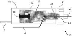
图2是图1中示出的超声激活单元的纵向截面示意图。FIG. 2 is a schematic longitudinal cross-sectional view of the ultrasonic activation unit shown in FIG. 1 .
图3对应于图2,但示出了耦接到单元外壳内的换能器的角状物。Figure 3 corresponds to Figure 2 but shows the horn coupled to the transducer within the unit housing.
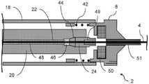
图4对应于图2,但示出了导丝从单元的换能器的侧向退出。Figure 4 corresponds to Figure 2 but shows the lateral exit of the guide wire from the transducer of the unit.
图5对应于图4,但示出了耦接到单元外壳内的换能器的角状物。Figure 5 corresponds to Figure 4 but shows the horn coupled to the transducer within the unit housing.
图6是图1中示出的超声激活单元的变体的纵向截面示意图,其中夹持可通过气动致动进行操作。Fig. 6 is a schematic longitudinal cross-sectional view of a variant of the ultrasonic activation unit shown in Fig. 1, wherein the gripping is operable by pneumatic actuation.
图7是本发明的超声激活单元的纵向截面示意图,其中超声到导线连接器和耦接机构包括用于施加扭矩的筒夹和弹簧加载的帽。7 is a schematic longitudinal cross-sectional view of an ultrasonically activated unit of the present invention, wherein the ultrasonic-to-wire connector and coupling mechanism includes a collet and a spring-loaded cap for applying torque.
图8示出了图7中示出的远侧阻尼器的替代性配置。FIG. 8 shows an alternative configuration of the distal damper shown in FIG. 7 .
图9示出了换能器的远侧凹陷内部的单锥形筒夹,具有近侧和远侧阻尼。Figure 9 shows a single conical collet inside the distal recess of the transducer with proximal and distal damping.
图10示出了换能器的远侧凹陷内部的双锥形筒夹,具有近侧阻尼。Figure 10 shows a biconical collet inside the distal recess of the transducer with proximal damping.
图11是示出外壳内用于阻尼近侧导线的内部特征的手持式超声激活单元的纵向截面视图。11 is a longitudinal cross-sectional view of the handheld ultrasound activation unit showing internal features within the housing for damping the proximal lead.
图12是包括抵消近侧导线活动的介质的手持式超声激活单元的纵向剖视图。12 is a longitudinal cross-sectional view of a hand-held ultrasound activation unit including media to counteract proximal lead activity.
图13是示出图12的细节的放大视图。FIG. 13 is an enlarged view showing details of FIG. 12 .
图14是用于接合和阻尼导线的凸轮布置的端部视图。14 is an end view of a cam arrangement for engaging and damping wires.
图15是包括按钮导线阻尼机构的手持式超声激活单元的纵向截面视图。15 is a longitudinal cross-sectional view of a handheld ultrasonic activation unit including a button wire damping mechanism.
图16a是包括螺旋导线阻尼机构的手持式超声激活单元的纵向截面视图。Figure 16a is a longitudinal cross-sectional view of a handheld ultrasonic activation unit including a helical wire damping mechanism.
图16b是图16a的手持式超声激活单元的横截面视图。Figure 16b is a cross-sectional view of the handheld ultrasound activation unit of Figure 16a.
图17是包括另一种导线阻尼机构的手持式超声激活单元的纵向截面视图。17 is a longitudinal cross-sectional view of a handheld ultrasonic activation unit including another wire damping mechanism.
图18是包括另一种导线阻尼机构的手持式超声激活单元的纵向截面视图,其可以根据需要脱离接合以允许重新定位导线。18 is a longitudinal cross-sectional view of a hand-held ultrasonic activation unit including another lead damping mechanism that can be disengaged as needed to allow repositioning of the lead.
图19是被布置成阻尼导线的近侧激励的纵向分裂筒夹的侧视图。19 is a side view of a longitudinal split collet arranged to damp proximal excitation of a lead.
图20是示出连接位置标记的实例的导线的示意图。FIG. 20 is a schematic diagram of a wire showing an example of connecting a position marker.
图21是本发明的装配有可拆卸的远侧安全和应力消除特征的超声激活单元的透视图。21 is a perspective view of an ultrasonic activation unit of the present invention equipped with removable distal safety and strain relief features.
图22是在手术期间使用的图21的布置的纵向截面视图。Figure 22 is a longitudinal cross-sectional view of the arrangement of Figure 21 used during surgery.
图23是示出在手术期间使用的图21的布置的透视图。Figure 23 is a perspective view showing the arrangement of Figure 21 in use during surgery.
图24是示出在手术期间使用的图21的布置的另一个透视图。Figure 24 is another perspective view showing the arrangement of Figure 21 in use during surgery.
图25是用于与本发明一起使用的保护性护套的示意图。Figure 25 is a schematic illustration of a protective sheath for use with the present invention.
图26示出了具有近侧阻尼特征的超声激活单元。Figure 26 shows an ultrasound activation unit with a proximal damping feature.
图27示出了具有近侧阻尼特征的另一个超声激活单元。Figure 27 shows another ultrasound activation unit with a proximal damping feature.
图28示出了具有近侧阻尼特征的又另一个超声激活单元。Figure 28 shows yet another ultrasound activation unit with a proximal damping feature.
图29示出了具有用于在两个点处夹持血管内导线的近侧和远侧扭锁的超声波激活单元。Figure 29 shows an ultrasound activation unit with proximal and distal twist locks for gripping the intravascular lead at two points.
图30a、30b和30c示出了用于减少血管内导线的侧向移动的三种凸出部布置。Figures 30a, 30b and 30c show three projection arrangements for reducing lateral movement of the intravascular guidewire.
图31示出了用于超声激活单元的近侧阻尼器的另一个实例。Figure 31 shows another example of a proximal damper for an ultrasound activation unit.
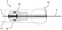
图32示出了具有近侧阻尼特征的又另一个超声激活单元。Figure 32 shows yet another ultrasound activation unit with a proximal damping feature.
图33示出了具有远侧阻尼特征的超声激活单元。Figure 33 shows an ultrasound activation unit with distal damping features.
图34a、34b和34c示出了通过选择性或间歇性地覆盖或围绕导线提供选择性或间歇性阻尼的运动阻尼导线护套的三个实例。Figures 34a, 34b and 34c show three examples of motion dampening wire sheaths that provide selective or intermittent damping by selectively or intermittently covering or surrounding the wire.
图35a和35b示出了远侧阻尼机构的变体。Figures 35a and 35b show a variation of the distal damping mechanism.
具体实施方式Detailed ways
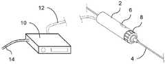
附图中的图1示出了根据本发明的系统的总体配置,并且展示了此类系统的一些主要组件。此实例以手持式超声激活单元2为特征,呈血管内导线4形式的柔性传送构件以中心对齐方式延伸穿过所述手持式超声激活单元。Figure 1 of the accompanying drawings shows the general configuration of a system according to the present invention and shows some of the main components of such a system. This example features a hand-held
导线4可以插入到患者的脉管系统中并穿过以将其远端带到病变位置。一旦遇到阻碍导线4穿过的复杂病变,激活单元2可以在合适的纵向位置处耦接到导线4。当被激活时,激活单元2将超声振动传送到导线4并沿着所述导线,从而通过消融和其它机制增强导线4穿过病变的能力。导线4由此用作用于穿过血管中的阻塞的交叉导线,并且然后可以保持在原位以用作用于递送后续治疗装置以治疗病变的导丝。The
典型地,导线4的长度例如可以大于2m并且至多3m。例如,进入足部中或穿过足部的病变可能涉及导线在脉管系统内行进通常1200mm到2000mm的距离,这取决于是选择同侧入路、对侧入路还是径向入路。在此方面,在其尖端处朝远侧锥形化为细线的导线4可以导航到足动脉并在背动脉与足底动脉之间围绕足弓。然而,本发明不限于足部或其它外周应用并且可以例如用于冠状动脉应用中,其中导线4导航到曲折小直径动脉并在所述曲折小直径动脉内挖掘的能力也是有益的。Typically, the length of the
导线4的远侧区段的直径将决定导线4的柔性以及其容易符合其打算穿过的解剖结构形状的能力。因此,例如,在曲折的(足部或冠状动脉)解剖结构中,适当长度、直径例如为0.005"到0.007"的远侧区段结合了适当的柔性和用于某些镍钛合金挖掘阻塞材料的能力。The diameter of the distal section of
激活单元2包含用户控件6以及任选地还包含显示器。激活单元2进一步包括远侧手动套索扣8,用户可以围绕单元2和导线4的中心纵向轴线转动所述远侧手动套索扣。特别地,激活单元2可以在导线4上滑动并且可以通过施加扭矩转动套索扣8在多个纵向间隔的位置处耦接到导线4。为了实现耦接,如后面的附图中示出的,套索扣8作用于激活单元2内的围绕导线4并与所述导线同轴的如筒夹等耦接件上。当套索扣8被拧紧时,筒夹夹住导线4,以任选地通过耦接到换能器或与换能器集成的放大器角状物,从激活单元2内的集成式超声换能器传送超声能量。在一些实施例中,导线4可以直接耦接到换能器,在此情况下可以省略角状物。The
套索扣8是可逆的以从导线4释放激活单元2。因此,为了不同的目的,设置为可以互换不同尺寸、配置或材料的导线4。还可以互换激活单元2内的换能器或角状物。The
图1示出了分解的布置,其中超声信号发生器10与激活单元2分离。在此示例中,超声信号发生器10通过连接器电缆12连接到激活单元2。在替代性布置中,超声信号发生器10可以并入到激活单元2的外壳中。图1中示出的实例具有外部供电的超声信号发生器10,并且因此包括连接到外部电源的电力电缆14。替代性实施例可以由内部电池供电,例如,可以将所述内部电池并入到超声信号发生器单元10或激活单元2中。FIG. 1 shows an exploded arrangement in which the
通常,系统的组件优选地是便携式的并且更优选地是手持式的。这些组件可以是无线的、可充电的、可重复使用的和可回收的。任何用于传输电力或信号的外部电缆12、14都可以通过滑环耦接,以允许电缆12、14自由旋转并且避免与导线4缠结。Generally, the components of the system are preferably portable and more preferably hand-held. These components can be wireless, rechargeable, reusable and recyclable. Any
现在继续前进到图2到5,这些附图示出了激活单元在纵向区段中的各种布置。相似的数字用于相似的特征。在这些实例中的每个实例中,激活单元2由外部供电并且任选地通过电缆12被提供超声信号,尽管如上所述独立的电池供电变体是可能的。Continuing now to Figures 2 to 5, these figures show various arrangements of activation units in longitudinal sections. Similar numbers are used for similar features. In each of these examples, the
图2示出了单元2的外壳18含有超声换能器20,所述超声换能器被中心端口或内腔22穿透以允许导线4的通过。换能器20的远侧部分具有螺纹区段以允许筒夹24的接合。稍后将描述各种筒夹概念。在此实例中,导线4延伸穿过换能器20的全长并且从外壳18向近侧露出。可压缩阻尼环45设置在筒夹24的近侧,以帮助使导线4的近侧部分的移动最小化。此阻尼环45可以由如聚合物或聚合物共混物等弹性材料(即可压缩和有弹性的)制成。FIG. 2 shows that the
图3示出了本发明的另一个实施例,其中声学角状物26附接到换能器20的远侧面。如这些声学角状物等声学角状物可与用于放大来自换能器20的远侧面的位移。为此目的,角状物26可以以连续锥形化的配置或以如图所示的阶梯配置向远侧锥形化。FIG. 3 shows another embodiment of the present invention in which an
在图3中示出的实例中,导线4通过筒夹24耦接到角状物26的远端或面。角状物26具有与超声换能器20中的内腔22对齐并与之连通的中心内腔22或通道。这允许导线4沿其共同的纵向轴线在中心行进穿过角状物26和换能器20。In the example shown in FIG. 3 ,
图4示出了与图2类似的配置,但在此情况下,导线4不在中心行进穿过超声换能器20的整个长度。相反,导线4在压电陶瓷堆28与筒夹24所在的换能器20的远端或前块状物30之间的位置处从换能器20侧向露出。FIG. 4 shows a configuration similar to that of FIG. 2 , but in this case the
相应地,图5示出了与图3类似的配置,但在此情况下,导线4不在中心行进穿过整个超声换能器20和角状物26,而是在筒夹24与换能器20的远侧面之间沿角状物26长度的位置处从角状物26侧向露出。因此,在图4和5中,导线4从换能器20或角状物26的中心纵向轴线偏转穿过锐角,以通过换能器20或角状物26的一侧侧向退出。Accordingly, Figure 5 shows a similar configuration to Figure 3, but in this case the
应当注意,图2到5中例示的本发明的布置不同于使用电动机和凸轮或心轴驱动导线振动以将旋转运动转换为线性运动的现有技术。相反,本发明使用超声换能器20,所述超声换能器包括压电陶瓷堆28以及前和后(或远侧和近侧)块状物。这采用压电陶瓷堆28的压电效应,其中电能被转换成高频轴向线性振荡。It should be noted that the arrangement of the present invention illustrated in Figures 2 to 5 differs from the prior art which uses a motor and a cam or spindle to drive wire vibration to convert rotational motion to linear motion. Instead, the present invention uses an
另外地,与现有技术不同,本发明允许导线4延伸穿过激活单元2并且仍然耦接到换能器20的远端,此表述包含可以任选地耦接到换能器20的远端的声学角状物26。当使用超声换能器时,现有技术没有用于允许导线在中心行进穿过至少换能器的远端的设置。本发明的此特征允许激活单元2沿导线4移动,并且然后被耦接以沿导线4在多个纵向间隔的位置中的任何位置处将超声能量传送到导线4。Additionally, unlike the prior art, the present invention allows the
图6示出了激活单元2,像图2中示出的布置一样,所述激活单元含有超声换能器20,所述超声换能器具有中心内腔22以允许导线4的直接通过。然而,在此情况下,换能器的远端包括气动微型卡盘32以允许导线4的接合和释放。卡盘32具有成角度间隔的夹爪,例如三个或四个夹爪,其直接或通过筒夹24作用在导线4上,从而以恒定的力夹持和释放导线4。FIG. 6 shows the
具体地,卡盘系统的气动激活将卡盘32压到导线4上,或压到安置在导线4周围的筒夹24上,从而以耦接从换能器20发出的超声能量所需的压力夹持导线4。空气管线压力可以用于调节由卡盘32施加的力,以便施加恒定的所需夹持力。螺线管可以用于控制导线4的捕获和释放以允许导线4相对于激活单元2纵向移动或变位。这允许将导线4锁定在原位并克服调节气压的可能变化。Specifically, pneumatic activation of the chuck system compresses the
在此实例中,与卡盘连通的压缩空气递送端口分支以限定辅助通道。辅助通道提供冷却气流以总体上冷却激活机构2并且特别是耦接区域。In this example, a compressed air delivery port in communication with the chuck branches off to define an auxiliary channel. The auxiliary channel provides a cooling air flow to cool the
将显而易见的是,图6中示出的气动卡盘32的原理也可以应用于采用声学角状物26或其中导线4侧向退出换能器20或角状物26的布置,像图3到5中示出的那些布置一样。为简洁起见,应当注意,此描述中对换能器20的引用可以指换能器20的前或远侧块状物30或指附接到换能器的远侧面的声学角状物26,因此有效地成为换能器20的整体部分。It will be apparent that the principles of the
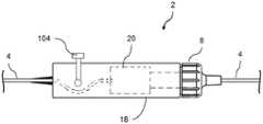
接下来转向附图的图7,激活单元2的外壳18是管状的并且同轴地围绕超声换能器20的前块状物。换能器20向远侧延伸到外壳的远端附近。在此示例中,导线4沿换能器20轴向延伸并且经由中心内腔22穿过所述换能器,但是导线4可以替代地如图4和5中侧向退出外壳18。同样,换能器20的前块状物可以用如图3和5中的声学角状物26代替。Turning next to FIG. 7 of the drawings, the
外壳18的远端由套索扣8封闭。套索扣8可以围绕导线4的中心纵向轴线转动,并且还可以抵靠外壳18内的弹簧42的远侧偏压在近侧方向上被轴向推动。弹簧42可以是离散弹簧,如螺旋弹簧,或者可以由如螺旋构件等弹性形成件形成,所述螺旋构件附接到外科18和/或套索扣8或与所述外壳和/或所述套索扣成一体。套索扣8在此示出为处于被弹簧42偏置远离换能器20的远端的远侧位置。更通常地,套索扣8相对于筒夹24的旋转和/或轴向移动可以由凸轮或花键形成件引导或确定。The distal end of the
换能器20的远端中的向远侧开口、向近侧锥形化的插口或凹陷44含有向近侧锥形化的筒夹24,所述筒夹围绕与换能器20的内腔22对齐的导线4。筒夹24具有与换能器20的远侧凹陷中的互补内螺纹接合的外螺纹。A distally open, proximally tapered socket or
筒夹24被拧入到换能器20的凹陷中,并且然后由操纵套索扣8的用户释放。具体地,用户首先在近侧方向上轴向推动套索扣8以接合筒夹24,并且然后转动套索扣8以使筒夹24沿凹陷内的螺纹向近侧推进,因此通过筒夹24将换能器20耦接到导线4。当由用户释放时,套索扣8向远侧弹回并因此从筒夹24脱离结合,从而不干扰从换能器20沿导线4传送超声能量。The
为此目的,筒夹24的远端部分从换能器20的远端向远侧突出。当克服弹簧42的偏置向近侧推动套索扣8时,套索扣8通过互补的界面形成件接合筒夹24的突出远端部分。套索扣8与筒夹24之间的此接合允许扭矩从套索扣8传送到筒夹24,因此使筒夹24沿凹陷内的螺纹向近侧推进。For this purpose, the distal end portion of the
当筒夹24以此方式拧入到换能器20的凹陷中时,筒夹和凹陷的互补的向近侧锥形化面导致筒夹24以沿导线4分布夹持力并避免点加载的方式向下夹持导线4。此夹持方法与筒夹24的材料的适当选择相结合,允许出色的配合和超声传送。换能器20和筒夹24的整个组合件被调谐以获得最佳谐振响应。When the
当导线4要从激活单元2释放时,可以通过再次将套索扣8向近侧按压到使其与筒夹24接合来释放筒夹24,并且然后在相反方向上转动套索扣8以沿换能器20的凹陷中的螺纹向远侧缩回筒夹24。这放松了筒夹24在导线4上的抓握,从而允许导线4从激活单元2中抽回。When the
任选地,如图7中示出的,内部阻尼器46可以安置在筒夹24的近端处。此阻尼器46在功能上类似于图2到5中示出的阻尼环45。在此实例中,内部阻尼器46是围绕换能器20的内腔22中的导线4的由超弹性材料制成的环形套环。当筒夹24拧入到换能器20的远侧凹陷中时,阻尼器46被轴向压缩并径向变厚,因此围绕导线4变形并压靠在所述导线上。阻尼器46由此阻尼或减弱换能器20给予的超声能量通过筒夹24到导线4的近侧传送。Optionally, as shown in FIG. 7 , an
图7还示出了围绕内腔22内的导线4布置的任选的内部保护性套筒48。套筒48由低摩擦、高耐磨材料制成,以使导线4在内腔22内居中并且遮蔽导线4使其不受换能器20的周围壁的影响。套筒48优选地由像阻尼器46一样的材料制成,所述材料对由换能器20施加到导线4的超声能量的近侧传送具有阻尼或减弱作用。类似的套筒49、51可以安置在筒夹24的远侧部分中并且在套索扣8与导线4之间,以在导线4从筒夹24向远侧露出时使所述导线在中心并支撑所述导线。套索扣8与导线4之间的套筒51可以部分地从其向远侧延伸。与设置在换能器20与导线4之间的套筒48一样,设置在筒夹24和套索扣8中的套筒49、51优选地被配置成对给予导线4的超声能量的近侧传送具有阻尼或减弱效果。FIG. 7 also shows an optional inner
图7中示出的另一个任选特征是套索扣8内的扭矩限制器50,当套索扣8与筒夹24接合时,所述扭矩限制器作用在套索扣8的外部与筒夹24之间。如果用户施加到套索扣8的扭矩超过预定限制,则扭矩限制器50例如通过套索扣8和/或筒夹24的柔性或弹性界面形成件的变形使套索扣8相对于筒夹24滑动。这防止用户通过向套索扣8施加过大的扭矩来过度拧紧筒夹24,这否则可以导致筒夹24过度压缩并且因此导致导线4承受过度应力并有故障的风险。Another optional feature shown in FIG. 7 is a
图7中示出的套索扣8还包含应变消除特征,所述应变消除特征在此通过围绕导线的向远侧锥形化形成件来举例说明。此特征缓解了导线4的扭结和可能的过度应力,其中导线4穿过套索扣8从激活单元2的外壳18露出。The
图8示出了图7中示出的两个远侧阻尼器的替代性配置。此处,基于筒夹的导线套筒49部分地从筒夹24向远侧延伸,并且基于套索扣的导线套筒51从套索扣8向近侧延伸。基于套索扣的导线套筒51也可以从套索扣8向远侧延伸。基于套索扣的导线套筒51的近端包围并且优选地夹持基于筒夹的导线套筒49的远端,使得获得两者之间的连续连接并且进一步改进激活单元2的远侧阻尼特性。可替代地,基于筒夹的导线套筒49的远端可以被配置成包围基于套索扣的导线套筒51的近端,具有类似的效果。FIG. 8 shows an alternative configuration of the two distal dampers shown in FIG. 7 . Here, the collet-based
图9示出了单锥形筒夹24,其中仅筒夹24的近端是锥形的,以便在换能器20的远侧凹陷44的基部处坐落到互补的锥形中。相反地,图10示出了双锥形筒夹24,其中筒夹24的远端也向远侧锥形化。FIG. 9 shows a single
本发明中使用的筒夹24的主要目的是在导线4与系统的其余部分之间实现出色的声学耦接。在此方面,换能器20和耦接方法必须一致地工作。特别地,带有任选地包含声学角状物的耦接接口部件的换能器20被设计为在系统的驱动频率下谐振。The primary purpose of the
选择换能器20的形状和尺寸以实现放大增益,同时确保系统保持接近其操作谐振频率。此外,为了容纳连接器而对换能器20的远侧驱动面进行的任何修改都必须考虑并且对于谐振响应进行考虑。The shape and dimensions of the
图9示出了装配有单锥外螺纹筒夹24的换能器20。当向筒夹24施加扭矩以将筒夹24推进到凹陷44中时,筒夹24将导线4锚定在换能器20的远端的互补螺纹孔或凹陷44内。在凹陷44的近侧基部处的互补锥形然后径向压缩筒夹24以夹持导线4。如图4中示出的,当筒夹24完全推进到凹陷44中时,筒夹24的远端部分从换能器20的远端向远侧突出。凹陷44的近端处的阻尼器46和类似于图7中示出的基于筒夹的套筒48的阻尼套筒48被提供用于阻尼或减弱由换能器20给予的超声能量到导线4的近侧传送。FIG. 9 shows the
图10示出了装配有双锥筒夹24和帽螺钉54的换能器20。筒夹24的近侧锥被接纳在换能器20的远端面中的沉头远侧凹陷44中。帽螺钉54类似地接纳筒夹24的远端处的锥并与其互补。施加到帽螺钉54的扭矩推进帽螺钉54以纵向压缩筒夹24并径向压缩筒夹24以夹持导线4。FIG. 10 shows the
像图7中示出的布置一样,内部阻尼器46安置在换能器20内的筒夹24的近端处。阻尼器46是围绕换能器20的内腔22中的导线4的由超弹性材料制成的环形套环。当筒夹24向近侧被迫使进入到换能器20的远侧凹陷44中时,阻尼器46被轴向压缩并径向变厚,因此围绕导线4变形并压靠在所述导线上。阻尼器46由此阻尼或减弱换能器20给予的超声能量通过筒夹24到导线4的近侧传送。在此布置中以及图7的布置中,多个阻尼器46或一个较长的阻尼器46可以部署在换能器主体20内的长度上。Like the arrangement shown in FIG. 7 , an
图11示出了激活单元2的外壳18内的内部阻尼特征,其中从换能器20向近侧露出的导线4的部分穿过一系列曲折的弯曲部94。引导导线4通过这些回旋弯曲部94减弱了超声能量并且因此减少了近侧传送。导线4的近侧部分也可以延伸穿过具有高摩擦系数的管96。在那种情况下,弯曲部94的作用增加了导线4与周围管96之间的摩擦力,导致超声能量进一步减弱。导线4与如限定弯曲部94的横向销98等特征之间也会产生摩擦。FIG. 11 shows the internal damping feature within the
另外,导线4的近侧部分可以滑动通过内径等于或小于导线的外径的硅树脂等超弹性管。为了举例说明前一种可能性,图12和13对应于图6的气动夹持布置,但示出了阻尼介质100,所述阻尼介质围绕气动微型卡盘32的近侧上的导线安置。Additionally, the proximal portion of the
同样,导线4的近侧部分可以通过独立于或连接到主用户套索扣8的机构被主动夹持或弯曲偏离中心。例如,图14示出了导线4的近侧部分如何被捕获在激活单元2内的偏移凸轮102之间。图15示出了可以径向向内地压靠在激活单元2内的导线4的近侧部分上的按钮阻尼机构104。按钮阻尼机构104被配置成对导线4施加压力,并且因此阻尼导线4的位移。Likewise, the proximal portion of the
在图16a中,激活单元2的外壳18在其近端装配有阻尼机构105,所述阻尼机构包括近侧帽,所述近侧帽可以转动以使侧向偏移的螺旋形成件与导线4的近侧部分阻尼接触。图16b示出了通过阻尼机构105的横截面视图。In Figure 16a, the
在图15和16a中将注意到,导线4的近侧部分被从外壳18向近侧延伸的应变消除特征包围,这也影响了导线4的侧向阻尼。It will be noted in Figures 15 and 16a that the proximal portion of the
图17举例说明了如何通过用户转动远侧套索扣8来自动实现近侧振动的调制。随着套索扣8被转动,激活单元2的外壳内的引导电缆106被移位。这拉动了弹簧加载元件108,所述弹簧加载元件通过摩擦套环110作用在导线4的近侧部分上,导线4的此部分延伸穿过所述摩擦套环。通过增加导线4上的摩擦力并限制其振动,这会减弱否则从激活单元2向近侧定向的超声能量。在其它实施例中,摩擦套环110可以以电子方式控制。然后可以将类似的远侧套索扣8用于通过远侧套索扣8与摩擦套环10之间的电子耦接来调整摩擦力。Figure 17 illustrates how modulation of the proximal vibration can be achieved automatically by the user turning the
图18示出了另一种方式,其中导线4的近侧部分可以被夹持以阻尼超声振荡。此处,激活单元2的外壳18支撑沿外壳18纵向延伸的杆112。杆112的近端被弹簧114偏置成与导线4的近侧部分阻尼接触。当期望从激活单元2取出导线4时,可以压下杆112的远端以释放由杆112施加到导线4的近侧部分的压力。Figure 18 shows another way in which the proximal portion of the
阻尼特征也可以并入筒夹24中。例如,图19示出了分裂筒夹24,其中导线4的近侧部分被迫使进入由筒夹24的相对面中的相对引导形成件76限定的蛇形路径中。具体地,纵向交错的凸出部76在筒夹24的相对部分之间交替,以在所述相对部分之间限定起伏的路径。凸出部76可以由顺应性材料制成以有效地阻尼激励。Damping features may also be incorporated into the
图20示出了换能器或角状物的内腔如何可以被注入泡沫或弹性聚合物材料以消除从耦接件和从激活单元向近侧延伸的导线的近侧部分中的活动。Figure 20 shows how the lumen of the transducer or horn can be injected with a foam or elastic polymer material to eliminate movement in the proximal portion of the lead extending proximally from the coupling and from the activation unit.
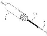
接下来转向图21到24,这些附图示出了安全特征,其中从激活单元2的远端向远侧突出的刚性管176围绕并包封导线4的远侧部分。管176的主要目的是防止手持式激活单元2在手术期间向远侧朝着患者推进很远以至于如果导线4断裂则可能存在导线4在患者身体内丢失的风险。管176的第二个益处是为导线4的远侧部分提供应力消除和侧向阻尼。Turning next to FIGS. 21 to 24 , these figures illustrate a safety feature in which a
特别地,如图22中示出的,管176用作防止用户将激活单元2一直推进到导管进入端口178的间隔件,所述导管进入端口在本领域中通常被称为“鲁尔接口(luer)”。管176的长度在激活单元2与进入端口178之间施加了相隔距离。如图所示,管176的远端可以是球状的或以其它方式扩大的,以用作防止管进入所述进入端口的端部止动件或插入限制器。In particular, as shown in FIG. 22, the
管176的长度确保即使导线4断裂,导线4的区段也将始终保持在患者身体外部。具体地,如果导线4在其与激活单元2内的换能器20的耦接点附近断裂,则至少与管176一样长并且通常略长于管176的一段导线4将始终保持在进入端口178的外部。在此情况下,导线4与管176之间的摩擦将有助于防止导线4沿管176向远侧滑动并进入患者身体内。The length of the
图23和24示出了管176可以具有在用户的手指之间可径向压缩的另外的属性,以便在断裂的情况下将导线4夹持在管176内。这帮助用户防止导线4的断裂端部被拉入患者身体内。管176可以以此方式在其近端处或沿其长度的任何点处可压缩,但优选地在其远端处或附近可压缩,如图所示。Figures 23 and 24 show that the
有利地,管176也可以容易地从激活单元2上分离,以允许快速接近导线4。出于此目的,通过从套索扣8的远侧释放管176的近端处的可拆卸连接器180,管176可容易地从激活单元2的远端拆卸。在那里,管176可以例如通过扭断或压/拉布置从激活单元2分离。Advantageously, the
因此,用户可以挤压管176以夹住断裂的导线4,并且然后在仍然夹住导线4的同时,可以将管176拉动远离激活单元2以确保导线4保持在患者身体外部。Thus, the user can squeeze the
现在继续前进到图25,此附图示出了柔性管状保护性导管或护套182。在手术开始时,护套182沿导线4的远侧部分延伸或围绕所述远侧部分延伸,所述导线在激活单元2与限定引导进入患者身体中的进入端口178的鲁尔接口或导引器之间延伸。护套182的目的是围绕并保护导线4的此长度,所述长度否则在被推进到患者身体中之前将被暴露。导线4可以容易地穿过松散的护套182,而护套182防止导线4与任何可能污染导线4或修改、特别是阻尼导线4的振荡的材料接触。Continuing now to FIG. 25 , a flexible tubular protective catheter or
护套182在必须将长导线4插入到患者身体中的情况下特别有用,例如以穿过远侧胫骨动脉或足部动脉中的堵塞。特别地,管182有助于将如此大长度的导线4以单次连续移动插入,而不是在连续较短的移动中间歇地插入,如果激活单元2相反地重复地夹持导线4并从导线4释放,则会出现这种情况。The
因此,代替保持靠近导引器178,激活单元2在远离导引器178的位置处耦接到导线4,并且因此准备好将导线4的全长引入到目标脉管中。因此,用户可以简单地在距患者身体一米或更远的近侧位置处将激活单元2夹持到导线4,并且然后可以在单个不间断动作中激活导线4的长区段并将所述长区段递送到身体中。Thus, instead of remaining close to the
护套182不得阻碍激活单元2和导线4朝导引器178的远侧移动。因此,当激活单元2和导线4向远侧推进时,护套182可以沿其长度或六角风琴状部分(concertina)塌缩。在另一种方法中,如此处示出的,护套182具有沿其长度的纵向狭缝184、凹槽拉链(groovezipper)或其它闭合件,以纵向分开并且然后从导线4剥离以在激活单元2和导线4一起向远侧推进穿过护套182时提供间隙。
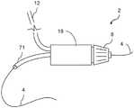
在图26中,导线4的近端的位移或移动被围绕导线4的近侧部分的柔性管状套筒71减小,所述导线在所述近侧部分处退出激活单元2的外壳18。这种例如由弹性聚合材料制成的柔性管状套筒抵靠导线4并且由此阻尼其移动。In FIG. 26 , the displacement or movement of the proximal end of the
图27示出了激活单元2的类似实施例。除了已经在图26中示出的之外,此实施例进一步包括将柔性管状套筒71挤压到导线71上的夹具72。夹具72可以可沿套筒71纵向移动到产生最佳阻尼效果的位置。在图28中,夹具72被筒夹73代替,所述筒夹也可以沿套筒71移动。另外地,筒夹73可以被适配成控制夹持力,所述筒夹通过所述夹持力夹持管状套筒71和延伸穿过其中的导线4。双筒夹73提供了阻尼特征,所述阻尼特征在轴向或纵向方向上压缩导线并且可以在多于一个点处夹持导线4。在另外的实施例中,图27的夹具72和图28的筒夹73可以组合。FIG. 27 shows a similar embodiment of the
在图29中,激活单元2包括近侧扭锁74,所述近侧扭锁夹持到导线4的近侧部分上并将所述导线耦接到激活单元2的外壳18以阻尼导线4的近侧部分的位移或移动。近侧扭锁74可以包括围绕导线4并通过操作近侧扭锁74而被拉紧的筒夹74a或管状套筒。除此之外,激活单元2可以包括具有将换能器耦接到导线4的远侧部分的筒夹75a的类似远侧扭锁75。扭锁74、75中的每个或两者,但优选地至少远侧扭锁75,可以与如图1和上文讨论的许多其它图中所公开的用户套索扣8组合。此类用户套索扣8然后将被配置成可独立于扭锁74、75围绕相同的纵向轴线旋转。另一种机构或操作者可以在锁定之前将导线4置于张力或受压状态,或者导线4可以在锁定前保持中性。In FIG. 29, the
图30a、30b和30c示出了导线保持形成件76的三种不同布置,所述保持形成件可以设置在激活单元2的外壳18内部,优选地至少在其近端,以便牢固地保持导线4并由此减弱其近侧部分的位移或移动。如图19中已经示出的,这些导线保持形成件76可以设置在筒夹24内部,或设置在围绕导线4的任何其它元件中并且刚性地安装在外壳18内部。导线保持形成件76可以是弹簧偏置的、抵靠导线4的近侧部分并且阻尼所述近侧部分的振动。在图30a中,四个导线保持形成件76一起提供与导线4的两个接触点。在图30b中,三个导线保持形成件76提供三个接触点。在图30c中,三个导线保持形成件76布置成使得导线4采用通过纵向交错的接触点的蜿蜒路径,类似于图19中示出的路径。图30a、30b和30c中示出的布置的组合和变化对于本领域技术人员将是显而易见的。应当进一步注意,类似的布置可以用于图11的实施例中的横向销98。Figures 30a, 30b and 30c show three different arrangements of
在图31的实施例中,提供了弹性塞子77或索环,所述弹性塞子或索环可以被推入到延伸穿过外壳18的中心端口22的近端中并抵靠延伸穿过其的导线4的近侧部分。塞子77被设计成紧密地配合到中心端口22的开口中,导线4延伸穿过所述开口。优选地,塞子77由橡胶或不同但类似地可模制和/或弹性材料制成。将塞子77推入到中心端口22中将导致弹性塞子77被压缩并且导线4被夹住,由此进一步阻尼导线4的近侧部分的侧向移动。In the embodiment of Fig. 31, a
在图32中,管状柔性膜78设置在外壳18的中心端口22内。管状柔性膜78限定了环形腔,所述环形腔可以通过穿过外壳18中的与所述腔连通的端口79施加流体压力而膨胀或充气。端口79可以连接到外部流体储存器并且泵可以将流体泵入到管状柔性膜78中以将膜78径向向内压靠导线4的近侧部分以阻尼导线4的此部分的振动。当流体压力被释放时,柔性膜78被放气并且中心端口22再次打开,由此允许导线4相对于激活单元2移动以用于调整、插入或取出导线4。流体可以是任何类型的液体,如水。可替代地,流体可以是空气,在这种情况下,膜78是气动操作的。虽然图32中示出的端口79被布置成连接到外部流体储存器,但替代性实施例可以使用集成在外壳18中的流体储存器。In FIG. 32 , a tubular
上文所描述的大多数实施例示出了用于阻尼导线4的近端中的移动的措施,主要是针对用户的安全以及避免损坏昂贵且敏感的设备以及实际上导线本身。然而,在激活单元2的远端处也可能期望对某些导线移动进行阻尼。适当的远侧阻尼通过主要通过纵向波将能量从换能器传输到导线4的有源远侧尖端部分来增加血管内设备的效率和功效,沿途不会因导线4的侧向移动而不必要地损失能量。Most of the embodiments described above show measures for damping movement in the proximal end of the
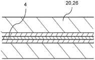
图33示出了可以实现导线4的远侧阻尼的一种方式。在此图中,薄护套81围绕从激活单元2的外壳18的远端露出的导线4的部分,以阻尼导线4的远侧部分的侧向振动。护套81的外径足够小以允许其装配到支撑导线4的导管内。在一实施例中,护套81可以实现为导线4的涂层,如涂漆层。Figure 33 shows one way in which distal damping of the
图34a、34b和34c提供了被配置成提供近侧和/或远侧阻尼的导管或护套的三种变体。这些护套中的每一个都可以是已参考图33讨论的离散套筒。此类离散套筒可以紧密地或松散地装配在导线4周围。可替代地,可以将护套涂覆或涂漆到导线4上。护套、套筒或涂层可以是如图34a中示出的连续护套82、如图34b中示出的螺旋状或螺旋形护套83或如图34c中示出的不连续或阶梯状护套84。护套可以沿其长度具有切出的窗口。因此,选择性或间歇性阻尼可以通过选择性或间歇性地覆盖或包围导线4来实现。间歇性覆盖可能会产生外径大于导线外径的离散区段。Figures 34a, 34b and 34c provide three variations of catheters or sheaths configured to provide proximal and/or distal damping. Each of these sheaths may be discrete sleeves as discussed with reference to FIG. 33 . Such discrete sleeves may fit tightly or loosely around the
所有护套82、83、84都具有增加导线4的重量和惯性的效果,并且由此限制导线4的被覆盖部分的移动。如果导线4的位移在与不连续或开窗护套的阻尼壁区段重合的位置处最大,则这可能对导线4的阻尼运动产生积极影响,如图34c中示出的。All
护套可以在其远端比在其近端更薄,使得导线4的远侧部分被允许装配在支撑导线4的导管内。为了维持激活单元2沿导线平移的可能性,在近端处的护套可以可沿导线4移动。替代性地,护套的区段被配置成在需要时可移除。在一实施例中,可以沿整个导线4提供相同的经涂覆的或涂漆的护套,仅在近端处具有可移除或可移动的另外的护套。The sheath may be thinner at its distal end than at its proximal end so that the distal portion of the
图35a和35b示出了远侧阻尼机构的变体,其中杆85可相对于外壳18枢转以抵靠从外壳内的换能器20的声学角状物26向远侧突出的导线4。杆85抵靠安置在角状物26与外壳18的远端之间的外壳18内的导线4的一部分。围绕导线4的应变消除特征从外壳18的此端部向远侧延伸。杆85可以如图35a中示出的直接抵靠在导线4上,或者如图35b中示出的通过插入在杆85与导线4之间的中间垫86间接地抵靠所述导线。Figures 35a and 35b show a variation of the distal damping mechanism in which the
应当注意,上文所描述的各种实施例的许多特征不仅限于那些具体实施例。技术人员将能够将来自一个实施例的特征与其它实施例的特征组合,只要这在技术上是可能的并且从实践的角度来看是有意义的。It should be noted that many of the features of the various embodiments described above are not limited to those specific embodiments. The skilled person will be able to combine features from one embodiment with features of other embodiments as long as this is technically possible and makes sense from a practical point of view.
Claims (40)
Applications Claiming Priority (5)
| Application Number | Priority Date | Filing Date | Title |
|---|---|---|---|
| PCT/EP2019/080449WO2020094747A2 (en) | 2018-11-06 | 2019-11-06 | Treatment of ischaemia |
| EPPCT/EP2019/080449 | 2019-11-06 | ||
| GBGB2006665.0AGB202006665D0 (en) | 2020-05-05 | 2020-05-05 | Treatment of ischaemia |
| GB2006665.0 | 2020-05-05 | ||
| PCT/EP2020/081386WO2021089847A1 (en) | 2019-11-06 | 2020-11-06 | Endovascular apparatus |
Publications (2)
| Publication Number | Publication Date |
|---|---|
| CN114901161Atrue CN114901161A (en) | 2022-08-12 |
| CN114901161B CN114901161B (en) | 2025-07-29 |
Family
ID=71080530
Family Applications (3)
| Application Number | Title | Priority Date | Filing Date |
|---|---|---|---|
| CN202080087139.8AActiveCN114901161B (en) | 2019-11-06 | 2020-11-06 | Intravascular device |
| CN202080089769.9APendingCN114901162A (en) | 2019-11-06 | 2020-11-06 | Guidewire for intravascular devices |
| CN202180045821.5APendingCN115720510A (en) | 2020-05-05 | 2021-05-05 | Treatment of Ischemia |
Family Applications After (2)
| Application Number | Title | Priority Date | Filing Date |
|---|---|---|---|
| CN202080089769.9APendingCN114901162A (en) | 2019-11-06 | 2020-11-06 | Guidewire for intravascular devices |
| CN202180045821.5APendingCN115720510A (en) | 2020-05-05 | 2021-05-05 | Treatment of Ischemia |
Country Status (8)
| Country | Link |
|---|---|
| US (7) | US11660104B2 (en) |
| EP (5) | EP4054446B1 (en) |
| JP (5) | JP7640108B2 (en) |
| CN (3) | CN114901161B (en) |
| AU (2) | AU2020380521A1 (en) |
| ES (2) | ES2960194T3 (en) |
| GB (1) | GB202006665D0 (en) |
| WO (3) | WO2021089847A1 (en) |
Families Citing this family (7)
| Publication number | Priority date | Publication date | Assignee | Title |
|---|---|---|---|---|
| GB202006665D0 (en) | 2020-05-05 | 2020-06-17 | Versono Medical Ltd | Treatment of ischaemia |
| GB202020065D0 (en) | 2020-12-17 | 2021-02-03 | Versono Medical Ltd | Acoustic characterisation of the effects on intralumenal wires |
| IT202100024116A1 (en)* | 2021-09-20 | 2023-03-20 | Enki Srl | DEVICE AND METHOD OF RELEASING A WIRE FROM A PIPE |
| CN119012977A (en) | 2021-12-17 | 2024-11-22 | 韦尔索诺医疗有限公司 | Apparatus and method for determining a condition of a structure in a body |
| WO2023183432A1 (en)* | 2022-03-22 | 2023-09-28 | Rutgers, The State University Of New Jersey | Neuroaspiration catheter for thrombectomy |
| CN116919535B (en)* | 2022-10-13 | 2024-05-07 | 以诺康医疗科技(苏州)有限公司 | Ultrasonic surgical blade |
| US20240207574A1 (en)* | 2022-12-21 | 2024-06-27 | Corindus, Inc. | Torque lmiting actuator for elongated medical device torquer |
Citations (9)
| Publication number | Priority date | Publication date | Assignee | Title |
|---|---|---|---|---|
| US5243997A (en)* | 1992-09-14 | 1993-09-14 | Interventional Technologies, Inc. | Vibrating device for a guide wire |
| US5382228A (en)* | 1992-07-09 | 1995-01-17 | Baxter International Inc. | Method and device for connecting ultrasound transmission member (S) to an ultrasound generating device |
| US5397293A (en)* | 1992-11-25 | 1995-03-14 | Misonix, Inc. | Ultrasonic device with sheath and transverse motion damping |
| CN202654235U (en)* | 2012-05-22 | 2013-01-09 | 刘建军 | Handle for ultrasonically clearing and breaking stones |
| US20130345617A1 (en)* | 2009-10-06 | 2013-12-26 | Michael P. Wallace | Methods and devices for removal of tissue, blood clots and liquids from the patient |
| CN104780858A (en)* | 2012-11-06 | 2015-07-15 | 迈迪生医疗器械公司 | Systems and methods for controlling delivery of ultrasonic energy to a bodily tissue |
| CN105188833A (en)* | 2013-05-21 | 2015-12-23 | 泰尔茂株式会社 | Catheter |
| CN106102619A (en)* | 2014-03-11 | 2016-11-09 | 美敦力阿迪安卢森堡有限公司 | With the independent conduit being radially expanded component and the device being associated, system and method |
| CN205852411U (en)* | 2016-07-31 | 2017-01-04 | 山西大同大学 | A kind of novel rotation non-contact ultrasonic power transfer |
Family Cites Families (72)
| Publication number | Priority date | Publication date | Assignee | Title |
|---|---|---|---|---|
| US3433226A (en) | 1965-07-21 | 1969-03-18 | Aeroprojects Inc | Vibratory catheterization apparatus and method of using |
| US4979939A (en) | 1984-05-14 | 1990-12-25 | Surgical Systems & Instruments, Inc. | Atherectomy system with a guide wire |
| US5284148A (en) | 1989-05-16 | 1994-02-08 | Hewlett-Packard Company | Intracavity ultrasound diagnostic probe using fiber acoustic waveguides |
| FR2653040B1 (en)* | 1989-10-18 | 1994-05-13 | Aerospatiale Ste Nationale Indle | ULTRASONIC PERCUSSION DEVICE. |
| US5248296A (en) | 1990-12-24 | 1993-09-28 | Sonic Needle Corporation | Ultrasonic device having wire sheath |
| US5447509A (en) | 1991-01-11 | 1995-09-05 | Baxter International Inc. | Ultrasound catheter system having modulated output with feedback control |
| US5542917A (en) | 1991-01-11 | 1996-08-06 | Baxter International, Inc. | Ultrasound delivery catheters incorporating improved distal tip construction |
| US5161534A (en) | 1991-09-05 | 1992-11-10 | C. R. Bard, Inc. | Tool for manipulating a medical guidewire |
| US5269297A (en)* | 1992-02-27 | 1993-12-14 | Angiosonics Inc. | Ultrasonic transmission apparatus |
| US5524635A (en) | 1992-09-14 | 1996-06-11 | Interventional Technologies Inc. | Apparatus for advancing a guide wire |
| SE9302356D0 (en)* | 1993-07-07 | 1993-07-07 | Siemens-Elema Ab | COUPLING FOR SELECTIVE CONNECTION OF PIPE PIPES AND SWITCHING DEVICE |
| US5427118A (en) | 1993-10-04 | 1995-06-27 | Baxter International Inc. | Ultrasonic guidewire |
| US5507738A (en)* | 1994-08-05 | 1996-04-16 | Microsonic Engineering Devices Company, Inc. | Ultrasonic vascular surgical system |
| US6241703B1 (en) | 1996-08-19 | 2001-06-05 | Angiosonics Inc. | Ultrasound transmission apparatus having a tip |
| US5971949A (en)* | 1996-08-19 | 1999-10-26 | Angiosonics Inc. | Ultrasound transmission apparatus and method of using same |
| US5846218A (en) | 1996-09-05 | 1998-12-08 | Pharmasonics, Inc. | Balloon catheters having ultrasonically driven interface surfaces and methods for their use |
| US6010449A (en) | 1997-02-28 | 2000-01-04 | Lumend, Inc. | Intravascular catheter system for treating a vascular occlusion |
| US5908395A (en) | 1997-03-17 | 1999-06-01 | Advanced Cardiovascular Systems, Inc. | Vibrating guidewire |
| EP0983615A1 (en) | 1997-05-19 | 2000-03-08 | Angiosonics Inc. | Feedback control system for ultrasound probe |
| US6007514A (en)* | 1997-09-30 | 1999-12-28 | Nita; Henry | Ultrasound system with pathfinding guidewire |
| US20040024393A1 (en) | 2002-08-02 | 2004-02-05 | Henry Nita | Therapeutic ultrasound system |
| US6855123B2 (en) | 2002-08-02 | 2005-02-15 | Flow Cardia, Inc. | Therapeutic ultrasound system |
| US6251110B1 (en)* | 1999-03-31 | 2001-06-26 | Ethicon Endo-Surgery, Inc. | Combined radio frequency and ultrasonic surgical device |
| US6758830B1 (en)* | 1999-05-11 | 2004-07-06 | Atrionix, Inc. | Catheter positioning system |
| US20050119679A1 (en)* | 1999-10-05 | 2005-06-02 | Omnisonics Medical Technologies, Inc. | Apparatus and method for an ultrasonic medical device to treat chronic total occlusions |
| US6695782B2 (en)* | 1999-10-05 | 2004-02-24 | Omnisonics Medical Technologies, Inc. | Ultrasonic probe device with rapid attachment and detachment means |
| US6450975B1 (en) | 1999-12-30 | 2002-09-17 | Advanced Cardiovascular Systems, Inc. | Ultrasonic transmission guide wire |
| JP2002085420A (en)* | 2000-09-19 | 2002-03-26 | Olympus Optical Co Ltd | Apparatus and method for ultrasonic coagulating and incising |
| US7211044B2 (en) | 2001-05-29 | 2007-05-01 | Ethicon Endo-Surgery, Inc. | Method for mapping temperature rise using pulse-echo ultrasound |
| JP4057524B2 (en) | 2001-08-20 | 2008-03-05 | 独立行政法人科学技術振興機構 | Ultrasound diagnostic system |
| US7831297B2 (en)* | 2003-05-24 | 2010-11-09 | Scottsdale Medical Devices, Inc. | Guide wire torque device |
| US8133236B2 (en)* | 2006-11-07 | 2012-03-13 | Flowcardia, Inc. | Ultrasound catheter having protective feature against breakage |
| US7137963B2 (en) | 2002-08-26 | 2006-11-21 | Flowcardia, Inc. | Ultrasound catheter for disrupting blood vessel obstructions |
| WO2004096061A1 (en)* | 2003-03-25 | 2004-11-11 | Omnisonics Medical Technologies, Inc. | Ultrasonic probe used with a pharmacological agent |
| US8734368B2 (en)* | 2003-09-04 | 2014-05-27 | Simon Fraser University | Percussion assisted angiogenesis |
| EP1827240A1 (en) | 2004-11-30 | 2007-09-05 | Omnisonics Medical Technologies, Inc. | Ultrasonic medical device with variable frequency drive |
| EP1890757B1 (en) | 2005-05-11 | 2013-02-27 | Eyoca Medical Ltd. | Device for opening vascular obstructions |
| US20070085614A1 (en) | 2005-09-06 | 2007-04-19 | Joseph Lockhart | Methods of enabling or disabling ultrasound vibration devices of ultrasound medical devices |
| EP1986568B1 (en) | 2006-02-03 | 2017-04-05 | Covidien LP | Methods and devices for restoring blood flow within blocked vasculature |
| US9282984B2 (en) | 2006-04-05 | 2016-03-15 | Flowcardia, Inc. | Therapeutic ultrasound system |
| US8246643B2 (en) | 2006-11-07 | 2012-08-21 | Flowcardia, Inc. | Ultrasound catheter having improved distal end |
| ITRE20060152A1 (en)* | 2006-12-15 | 2008-06-16 | Franco Baldi | IMPROVEMENTS TO OBSTACLE DETECTORS WITH COLLIMATION AND FOCUSING OF THE EMBED WAVE. |
| JP2009000586A (en) | 2007-06-19 | 2009-01-08 | Terumo Corp | Ultrasound generator and ultrasound generating system |
| US20090105815A1 (en)* | 2007-10-19 | 2009-04-23 | Matthew Krever | Push-in retainer system for use in the direct plication annuloplasty treatment of mitral valve regurgitation |
| WO2009141810A2 (en) | 2008-05-23 | 2009-11-26 | Oscillon Ltd | Method and device for recanalization of total occlusions |
| EP2349455B1 (en)* | 2008-10-31 | 2017-01-18 | QIG Group, LLC | Lead extension |
| CN102497827B (en)* | 2009-07-15 | 2016-06-01 | 伊西康内外科公司 | Electrosurgical generator for ultrasonic surgical instrument |
| CA2770743C (en) | 2009-08-14 | 2018-05-01 | Ethicon Endo-Surgery, Inc. | Ultrasonic surgical apparatus and silicon waveguide and methods for use thereof |
| EP3508244A1 (en) | 2010-02-09 | 2019-07-10 | Medinol Ltd. | System for traversing vessel occlusions |
| RU2640564C2 (en) | 2012-08-02 | 2018-01-09 | Бард Периферэл Васкьюлар | Ultrasonic catheter system |
| US9592027B2 (en) | 2013-03-14 | 2017-03-14 | Volcano Corporation | System and method of adventitial tissue characterization |
| EP3050528A4 (en)* | 2013-09-27 | 2017-06-21 | Olympus Corporation | Probe unit, treatment tool, and treatment system |
| WO2016081026A1 (en)* | 2014-11-19 | 2016-05-26 | C.R. Bard, Inc. | Ultrasound catheter and system with multiple function modes |
| WO2016081025A1 (en) | 2014-11-19 | 2016-05-26 | C.R. Bard, Inc. | Ultrasound transducer system for use with an ultrasound catheter |
| US9763684B2 (en)* | 2015-04-02 | 2017-09-19 | Med-Sonics Corporation | Devices and methods for removing occlusions from a bodily cavity |
| GB2557500B8 (en)* | 2015-07-29 | 2021-02-17 | Actuated Medical Inc | Devices for clearing blockages in artificial and natural lumens |
| US20170215837A1 (en) | 2016-01-29 | 2017-08-03 | Boston Scientific Limited | Acoustic sensor based guidewire |
| US10357262B2 (en) | 2016-11-14 | 2019-07-23 | C. R. Bard, Inc. | Systems and methods to modify intravascular lesions |
| US20180140321A1 (en)* | 2016-11-23 | 2018-05-24 | C. R. Bard, Inc. | Catheter With Retractable Sheath And Methods Thereof |
| EP3330728B1 (en)* | 2017-05-22 | 2020-10-21 | Siemens Healthcare GmbH | Method for vascular imaging with the aid of an mr equipment |
| US10820920B2 (en)* | 2017-07-05 | 2020-11-03 | Ethicon Llc | Reusable ultrasonic medical devices and methods of their use |
| US10987247B2 (en)* | 2017-10-18 | 2021-04-27 | Jesus Moreno | Opthalmic microsurgical instrument |
| US20190125302A1 (en) | 2017-10-31 | 2019-05-02 | Koninklijke Philips N.V. | Accelerometer in handle for ultrasound medical imaging device |
| EP4215133B1 (en)* | 2017-11-10 | 2025-01-01 | C. R. Bard, Inc. | Heat sinks for catheters and systems thereof |
| US11234676B2 (en)* | 2018-01-29 | 2022-02-01 | Elekta Ltd. | Probe holder for ultrasound imaging device |
| WO2019152898A1 (en) | 2018-02-03 | 2019-08-08 | Caze Technologies | Surgical systems with sensing and machine learning capabilities and methods thereof |
| CN209173124U (en)* | 2018-07-11 | 2019-07-30 | 杜学军 | A kind of automatic Superficial veins puncture and intubation equipment |
| US20200114041A1 (en)* | 2018-10-15 | 2020-04-16 | Avent, Inc. | Systems and methods for delivering a polymeric material to a treatment site during a radio frequency ablation procedure |
| GB201906743D0 (en) | 2019-05-13 | 2019-06-26 | Versono Medical Ltd | Compact uitrasonic endovascular occlusion crossing guidewire system |
| JP2022543732A (en)* | 2019-06-18 | 2022-10-14 | シー・アール・バード・インコーポレーテッド | Ultrasound system and method with improved occlusion engagement during crossing and atherectomy procedures |
| GB202006665D0 (en) | 2020-05-05 | 2020-06-17 | Versono Medical Ltd | Treatment of ischaemia |
| GB202020065D0 (en) | 2020-12-17 | 2021-02-03 | Versono Medical Ltd | Acoustic characterisation of the effects on intralumenal wires |
- 2020
- 2020-05-05GBGBGB2006665.0Apatent/GB202006665D0/ennot_activeCeased
- 2020-11-06CNCN202080087139.8Apatent/CN114901161B/enactiveActive
- 2020-11-06AUAU2020380521Apatent/AU2020380521A1/enactivePending
- 2020-11-06CNCN202080089769.9Apatent/CN114901162A/enactivePending
- 2020-11-06WOPCT/EP2020/081386patent/WO2021089847A1/ennot_activeCeased
- 2020-11-06USUS17/775,022patent/US11660104B2/enactiveActive
- 2020-11-06ESES20816410Tpatent/ES2960194T3/enactiveActive
- 2020-11-06USUS17/775,137patent/US11696774B2/enactiveActive
- 2020-11-06EPEP20816410.3Apatent/EP4054446B1/enactiveActive
- 2020-11-06JPJP2022526026Apatent/JP7640108B2/enactiveActive
- 2020-11-06JPJP2022526027Apatent/JP7481035B2/enactiveActive
- 2020-11-06ESES20816409Tpatent/ES2959991T3/enactiveActive
- 2020-11-06EPEP20816409.5Apatent/EP4054445B1/enactiveActive
- 2020-11-06WOPCT/EP2020/081399patent/WO2021089859A1/ennot_activeCeased
- 2020-11-06AUAU2020379232Apatent/AU2020379232A1/enactivePending
- 2020-11-06EPEP23195560.0Apatent/EP4295792A3/enactivePending
- 2021
- 2021-05-05EPEP21728438.9Apatent/EP4146095A1/ennot_activeWithdrawn
- 2021-05-05JPJP2022567231Apatent/JP2023524762A/enactivePending
- 2021-05-05EPEP24221911.1Apatent/EP4501259A3/enactivePending
- 2021-05-05CNCN202180045821.5Apatent/CN115720510A/enactivePending
- 2021-05-05WOPCT/EP2021/061925patent/WO2021224357A1/ennot_activeCeased
- 2022
- 2022-05-06USUS17/662,304patent/US12059162B2/enactiveActive
- 2022-11-07USUS18/053,013patent/US20230089070A1/ennot_activeAbandoned
- 2022-11-07USUS18/053,078patent/US20230066121A1/ennot_activeAbandoned
- 2024
- 2024-01-26USUS18/424,243patent/US20240423652A1/enactivePending
- 2024-04-18JPJP2024067390Apatent/JP7680791B2/enactiveActive
- 2024-07-16USUS18/774,276patent/US20250009371A1/enactivePending
- 2025
- 2025-06-27JPJP2025108974Apatent/JP2025133774A/enactivePending
Patent Citations (9)
| Publication number | Priority date | Publication date | Assignee | Title |
|---|---|---|---|---|
| US5382228A (en)* | 1992-07-09 | 1995-01-17 | Baxter International Inc. | Method and device for connecting ultrasound transmission member (S) to an ultrasound generating device |
| US5243997A (en)* | 1992-09-14 | 1993-09-14 | Interventional Technologies, Inc. | Vibrating device for a guide wire |
| US5397293A (en)* | 1992-11-25 | 1995-03-14 | Misonix, Inc. | Ultrasonic device with sheath and transverse motion damping |
| US20130345617A1 (en)* | 2009-10-06 | 2013-12-26 | Michael P. Wallace | Methods and devices for removal of tissue, blood clots and liquids from the patient |
| CN202654235U (en)* | 2012-05-22 | 2013-01-09 | 刘建军 | Handle for ultrasonically clearing and breaking stones |
| CN104780858A (en)* | 2012-11-06 | 2015-07-15 | 迈迪生医疗器械公司 | Systems and methods for controlling delivery of ultrasonic energy to a bodily tissue |
| CN105188833A (en)* | 2013-05-21 | 2015-12-23 | 泰尔茂株式会社 | Catheter |
| CN106102619A (en)* | 2014-03-11 | 2016-11-09 | 美敦力阿迪安卢森堡有限公司 | With the independent conduit being radially expanded component and the device being associated, system and method |
| CN205852411U (en)* | 2016-07-31 | 2017-01-04 | 山西大同大学 | A kind of novel rotation non-contact ultrasonic power transfer |
Also Published As
Similar Documents
| Publication | Publication Date | Title |
|---|---|---|
| CN114901161B (en) | Intravascular device | |
| US11109884B2 (en) | Steerable ultrasound catheter | |
| EP2609878B1 (en) | Improved ultrasound catheter devices | |
| ES2940766T3 (en) | Treatment of ischemia |
Legal Events
| Date | Code | Title | Description |
|---|---|---|---|
| PB01 | Publication | ||
| PB01 | Publication | ||
| SE01 | Entry into force of request for substantive examination | ||
| SE01 | Entry into force of request for substantive examination | ||
| GR01 | Patent grant | ||
| GR01 | Patent grant |