CN114901121A - Ophthalmic microscope with synchronized light source and camera - Google Patents
Ophthalmic microscope with synchronized light source and cameraDownload PDFInfo
- Publication number
- CN114901121A CN114901121ACN202080091420.9ACN202080091420ACN114901121ACN 114901121 ACN114901121 ACN 114901121ACN 202080091420 ACN202080091420 ACN 202080091420ACN 114901121 ACN114901121 ACN 114901121A
- Authority
- CN
- China
- Prior art keywords
- light
- camera
- microscope
- frame
- pulses
- Prior art date
- Legal status (The legal status is an assumption and is not a legal conclusion. Google has not performed a legal analysis and makes no representation as to the accuracy of the status listed.)
- Granted
Links
Images

Classifications
- A—HUMAN NECESSITIES
- A61—MEDICAL OR VETERINARY SCIENCE; HYGIENE
- A61B—DIAGNOSIS; SURGERY; IDENTIFICATION
- A61B3/00—Apparatus for testing the eyes; Instruments for examining the eyes
- A61B3/0008—Apparatus for testing the eyes; Instruments for examining the eyes provided with illuminating means
- A—HUMAN NECESSITIES
- A61—MEDICAL OR VETERINARY SCIENCE; HYGIENE
- A61B—DIAGNOSIS; SURGERY; IDENTIFICATION
- A61B3/00—Apparatus for testing the eyes; Instruments for examining the eyes
- A61B3/10—Objective types, i.e. instruments for examining the eyes independent of the patients' perceptions or reactions
- A61B3/13—Ophthalmic microscopes
- A61B3/135—Slit-lamp microscopes
- A—HUMAN NECESSITIES
- A61—MEDICAL OR VETERINARY SCIENCE; HYGIENE
- A61B—DIAGNOSIS; SURGERY; IDENTIFICATION
- A61B3/00—Apparatus for testing the eyes; Instruments for examining the eyes
- A61B3/10—Objective types, i.e. instruments for examining the eyes independent of the patients' perceptions or reactions
- A61B3/14—Arrangements specially adapted for eye photography
- A—HUMAN NECESSITIES
- A61—MEDICAL OR VETERINARY SCIENCE; HYGIENE
- A61B—DIAGNOSIS; SURGERY; IDENTIFICATION
- A61B2560/00—Constructional details of operational features of apparatus; Accessories for medical measuring apparatus
- A61B2560/02—Operational features
- A61B2560/0223—Operational features of calibration, e.g. protocols for calibrating sensors
Landscapes
- Life Sciences & Earth Sciences (AREA)
- Health & Medical Sciences (AREA)
- Medical Informatics (AREA)
- Molecular Biology (AREA)
- Ophthalmology & Optometry (AREA)
- Engineering & Computer Science (AREA)
- Biomedical Technology (AREA)
- Heart & Thoracic Surgery (AREA)
- Physics & Mathematics (AREA)
- Biophysics (AREA)
- Surgery (AREA)
- Animal Behavior & Ethology (AREA)
- General Health & Medical Sciences (AREA)
- Public Health (AREA)
- Veterinary Medicine (AREA)
- Eye Examination Apparatus (AREA)
- Microscoopes, Condenser (AREA)
- Investigating Or Analysing Materials By Optical Means (AREA)
Abstract
Translated fromChinese
Description
Translated fromChinese技术领域technical field
本发明涉及眼科显微镜,特别是裂隙灯显微镜,其具有适于在眼睛上生成照明脉冲的照明设备和具有用于记录眼睛的图像的相机的显微镜设备。本发明还涉及用于操作这种设备的方法。The present invention relates to an ophthalmic microscope, in particular a slit lamp microscope, having an illumination device adapted to generate illumination pulses on the eye and a microscope device having a camera for recording images of the eye. The invention also relates to a method for operating such a device.
背景技术Background technique
EP 2549913描述了一种眼科显微镜,其具有生成照明脉冲的照明设备以及具有相机的显微镜。脉动的光与相机同步,以便在记录相机帧时具有定义的照明。EP 2549913 describes an ophthalmic microscope with an illumination device generating illumination pulses and a microscope with a camera. The pulsating light is synchronized with the camera to have defined lighting when recording camera frames.
发明内容SUMMARY OF THE INVENTION
本发明要解决的问题是为这种显微镜提供改进的控制。The problem to be solved by the present invention is to provide improved control for such microscopes.
这个问题通过根据独立权利要求的设备和方法来解决。This problem is solved by a device and method according to the independent claims.
因而,本发明涉及至少包括以下元件的眼科显微镜:Thus, the present invention relates to an ophthalmic microscope comprising at least the following elements:
i)生成照明脉冲的照明设备:照明设备适于并被构造为生成用于照亮待检查的眼睛的单独的光脉冲。它至少包括以下元件:i) Illumination device generating illumination pulses: The illumination device is adapted and configured to generate individual light pulses for illuminating the eye to be examined. It includes at least the following elements:
a)至少一个光源:这是照明设备中生成光的部分。a) At least one light source: this is the part of the lighting device that generates light.
b)空间光调制器:这个部分被构造为对光进行空间调制。例如,它可以是静态狭缝,但有利地是电子控制的光调制器。b) Spatial Light Modulator: This section is configured to spatially modulate light. For example, it could be a static slit, but advantageously an electronically controlled light modulator.
c)照明成像光学器件:这个部分被构造为将光投影到眼睛上。有利地,它将空间光调制器的图像投影到眼睛上,从而在眼睛上生成定义的照明图案。c) Illumination Imaging Optics: This part is configured to project light onto the eye. Advantageously, it projects the image of the spatial light modulator onto the eye, thereby generating a defined illumination pattern on the eye.
ii)显微镜设备:显微镜设备适于记录眼睛的图像。它至少包括以下元件:ii) Microscope equipment: Microscope equipment is suitable for recording images of the eye. It includes at least the following elements:
a)显微镜光学器件:显微镜光学器件生成眼睛的图像。a) Microscope optics: Microscope optics generate an image of the eye.
b)至少一个电子相机:该相机适于记录来自显微镜光学器件的投影的图像。b) At least one electronic camera: the camera is adapted to record projected images from microscope optics.
iii)控制单元:控制单元控制设备的元件的操作。iii) Control unit: The control unit controls the operation of the elements of the device.
根据本发明的第一方面,相机具有帧信号输出,该帧信号输出携带指示相机记录帧的时间的信号。特别地,它可以生成与它所采用的每一帧同步的单个脉冲,即,与那个帧的积分阶段同步。According to a first aspect of the invention, the camera has a frame signal output that carries a signal indicating the time at which the camera recorded the frame. In particular, it can generate a single pulse synchronized with each frame it takes, ie with the integration phase of that frame.
控制单元被构造为使照明设备与这个帧信号输出同步。这允许独立地运行相机,例如,以其原生自由运行模式,这允许更快的帧速率。因此,在这种配置中,相机充当主设备,而照明设备充当与主设备的定时同步的从设备。The control unit is configured to synchronize the lighting device with this frame signal output. This allows running the camera independently, for example, in its native free-running mode, which allows for faster frame rates. Thus, in this configuration, the camera acts as a master device and the lighting device acts as a slave device synchronized with the timing of the master device.
在本发明的第二方面,控制单元被构造为对于由相机记录的每一帧在眼睛上生成至少两个照明脉冲。这样做的好处是眼睛看到的光脉冲速率高于相机的帧速率,从而降低了闪烁效应刺激患者的风险。In a second aspect of the invention, the control unit is configured to generate at least two illumination pulses on the eye for each frame recorded by the camera. The benefit of this is that the eye sees light pulses at a higher rate than the camera's frame rate, reducing the risk of flickering effects irritating the patient.
本发明还涉及用于操作眼科显微镜,特别是如上面所提到的显微镜的方法。与上述相同,显微镜至少包括以下元件:The invention also relates to a method for operating an ophthalmic microscope, in particular a microscope as mentioned above. As above, the microscope includes at least the following elements:
i)生成照明脉冲的照明设备:照明设备适于并被构造为生成用于照亮待检查的眼睛的单独的光脉冲。它至少包括以下元件:i) Illumination device generating illumination pulses: The illumination device is adapted and configured to generate individual light pulses for illuminating the eye to be examined. It includes at least the following elements:
a)至少一个光源:这是照明设备中生成光的部分。a) At least one light source: this is the part of the lighting device that generates light.
b)空间光调制器:这个部分被构造为对光进行空间调制。例如,它可以是静态狭缝,但有利地是电子控制的光调制器。b) Spatial Light Modulator: This section is configured to spatially modulate light. For example, it could be a static slit, but advantageously an electronically controlled light modulator.
c)照明成像光学器件:这个部分被构造为将光投影到眼睛上。有利地,它将空间光调制器的图像投影到眼睛上,从而在眼睛上生成定义的照明图案。c) Illumination Imaging Optics: This part is configured to project light onto the eye. Advantageously, it projects the image of the spatial light modulator onto the eye, thereby generating a defined illumination pattern on the eye.
ii)显微镜设备:显微镜设备适于记录眼睛的图像。它至少包括以下元件:ii) Microscope equipment: Microscope equipment is suitable for recording images of the eye. It includes at least the following elements:
a)显微镜光学器件:显微镜光学器件生成眼睛的图像。a) Microscope optics: Microscope optics generate an image of the eye.
b)至少一个电子相机:该相机适于记录来自显微镜光学器件的投影的图像。b) At least one electronic camera: the camera is adapted to record projected images from microscope optics.
iii)控制单元:控制单元控制设备的元件的操作。iii) Control unit: The control unit controls the operation of the elements of the device.
该方法包括借助于相机顺序地记录帧的步骤。The method includes the step of sequentially recording frames by means of a camera.
根据本发明的第一方面,该方法包括借助于照明设备生成与相机的帧信号输出同步的光脉冲的步骤。According to a first aspect of the invention, the method comprises the step of generating, by means of the lighting device, light pulses synchronized with the frame signal output of the camera.
根据本发明的第二方面,该方法还包括借助于照明设备为由相机记录的每一帧生成至少两个照明脉冲的步骤。According to a second aspect of the invention, the method further comprises the step of generating at least two illumination pulses for each frame recorded by the camera by means of the illumination device.
本发明的两个方面可以单独使用或组合使用。The two aspects of the invention may be used alone or in combination.
有利地,相机以其“自由运行模式”运行。在自由运行模式下,相机不记录与外部触发器信号同步的帧,而是在完成记录和处理前一帧后立即记录下一帧。在自由运行模式下,相机可以达到比借助于外部源触发记录帧时更高的帧速率。Advantageously, the camera operates in its "free running mode". In free-running mode, the camera does not record a frame synchronized with an external trigger signal, but instead records the next frame as soon as it finishes recording and processing the previous frame. In free-running mode, the camera can achieve higher frame rates than when recording frames triggered by an external source.
有利地,空间光调制器是电子控制的空间光调制器,其包括可独立控制的像素的二维阵列,其可以通过设备的控制单元同步到相机的帧信号输出。Advantageously, the spatial light modulator is an electronically controlled spatial light modulator comprising a two-dimensional array of independently controllable pixels, which can be synchronized to the camera's frame signal output by the control unit of the device.
在一个实施例中,空间光调制器可以包括微反射镜的二维阵列,微反射镜可单独偏转到第一和第二位置。第一位置可以例如与像素的开启状态对应并且第二位置可以例如与像素的关闭状态对应。在这种上下文中,微反射镜有利地具有小于1mm2的面积,特别是小于100μm2。In one embodiment, the spatial light modulator may comprise a two-dimensional array of micromirrors that are individually deflectable to the first and second positions. The first position may eg correspond to the on state of the pixel and the second position may eg correspond to the off state of the pixel. In this context, the micromirrors advantageously have an area of less than 1 mm2 , in particular less than 100 μm2 .
光源有利地是脉动的,即,控制单元被构造为使光源脉动。有利地,这是以与相机的帧信号输出同步的方式完成的。The light source is advantageously pulsating, ie the control unit is configured to pulse the light source. Advantageously, this is done in synchronization with the camera's frame signal output.
如果显微镜使用脉动的照明以及具有单独可控像素的阵列的光调制器,那么控制单元可以适于:If the microscope uses pulsating illumination and a light modulator with an array of individually controllable pixels, the control unit can be adapted to:
-在给定光脉冲之前的暗阶段期间将像素带入到给定配置,以及- bring pixels into a given configuration during a dark phase preceding a given light pulse, and
-仅当像素处于期望配置时才启动光脉冲。- Light pulses are initiated only when the pixel is in the desired configuration.
在这种情况下,暗阶段是在利用光脉冲来设置光调制器之前。这种设置可以花费一些时间,例如,因为像素慢或者因为将图案信息顺序地馈送到光调制器中要花费时间,因此最好在光脉冲之前完成。In this case, the dark phase is before the light pulses are used to set the light modulator. This setup can take some time, for example, because the pixels are slow or because it takes time to sequentially feed the pattern information into the light modulator, and is best done before the light pulse.
该方法或控制单元可以适于执行至少以下两个步骤:The method or control unit may be adapted to perform at least the following two steps:
-预测相机将记录下一帧的时间:这个预测取决于相机记录至少一个前一帧的时间而做出。特别地,它可以取决于相机记录前几帧的时间。- Predict when the camera will record the next frame: This prediction is made depending on when the camera records at least one previous frame. In particular, it can depend on when the camera recorded the first few frames.
-在用于记录下一帧的预测的时间之前准备照明设备的至少一部分。- preparing at least a part of the lighting device before the predicted time for recording the next frame.
这允许在帧被记录之前设置照明光学器件的至少一部分,例如空间光调制器,从而允许更明确的图像记录。这在本发明的第一方面中是特别有利的。This allows at least a portion of the illumination optics, such as a spatial light modulator, to be positioned before the frame is recorded, allowing for more defined image recording. This is particularly advantageous in the first aspect of the invention.
该设备还可以包括若干光源和至少一个光检测器,光检测器适于测量在光源和空间光调制器之间的位置处的光强度,即,独立于光调制器的状态的光源的亮度。在那种情况下,该方法或控制单元可以适于执行至少以下两个步骤:The device may further comprise several light sources and at least one light detector adapted to measure the light intensity at a position between the light source and the spatial light modulator, ie the brightness of the light source independent of the state of the light modulator. In that case, the method or control unit may be adapted to perform at least the following two steps:
-使光调制器进入非透射模式:在这种模式下,即使光源开启,也不会有光投影到眼睛上。- Put the light modulator into a non-transmissive mode: In this mode, no light is projected onto the eye even if the light source is on.
-当光调制器处于这种非透射模式时,使一个光源脉动以测量这个光源的亮度。- When the light modulator is in this non-transmissive mode, pulse a light source to measure the brightness of this light source.
这允许间歇地—特别是在记录一系列图像帧时—控制光源的当前亮度。然后,这个信息可以被用于例如在光脉冲期间调整通过光源的电流,同时在记录帧时记录光调制器的像素的开启时间的帧,以便实现定义的照明。This allows intermittently - especially when recording a series of image frames - to control the current brightness of the light source. This information can then be used, for example, to adjust the current through the light source during the light pulse, while recording the frame of the on-time of the pixels of the light modulator as the frame is recorded, in order to achieve a defined illumination.
附图说明Description of drawings
当考虑下面的详细描述时,将更好地理解本发明并且除上述那些之外的其它目的将变得显而易见。这种描述参考附图,其中:The present invention will be better understood and objects other than those described above will become apparent upon consideration of the following detailed description. This description refers to the accompanying drawings, in which:
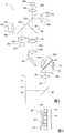
图1示出了眼科显微镜的实施例,Figure 1 shows an example of an ophthalmic microscope,
图2示出了照明设备的部件的实施例,Figure 2 shows an embodiment of the components of the lighting device,
图3是基于微反射镜的空间光调制器的示意性表示,以及Figure 3 is a schematic representation of a micromirror-based spatial light modulator, and
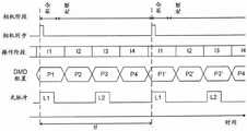
图4示出了用于设备的各种部件的时序图的实施例。Figure 4 shows an embodiment of a timing diagram for various components of a device.
具体实施方式Detailed ways
概述Overview
图1示出了眼科显微镜的实施例,特别是裂隙灯显微镜。Figure 1 shows an example of an ophthalmic microscope, in particular a slit lamp microscope.
显微镜具有例如搁置在桌子上的底座1、安装到底座1的可平移位移的载物台2、第一臂3和第二臂4。The microscope has, for example, a base 1 resting on a table, a translationally displaceable stage 2 mounted to the base 1 , a
载物台2可以相对于底座1沿着水平方向x和z线性位移。The stage 2 is linearly displaceable relative to the base 1 along the horizontal directions x and z.
臂3和4安装到载物台2上并且绕共同的竖直枢轴5(即,平行于竖直方向y的轴)枢转。The
该设备还可以包括安装到底座1的用于接纳患者的头部的头枕7。The apparatus may also include a
臂3承载显微镜设备8,并且臂4承载照明设备9(诸如裂隙灯)。
显微镜设备8具有光轴12。它包括显微镜光学器件14、15(诸如物镜14和变焦光学器件15),它们将眼睛10的图像投影到相机16和可选地目镜18上。可以提供分束器20以在这些部件之间拆分光。The
照明设备9适于将结构化的光束投影到待检查的眼睛10上。它包括光源22、空间光调制器24和照明成像光学器件26。The
光源22例如可以包括发射不同波长的几个单元,例如在光谱的红色、绿色、蓝色和红外范围内。这些单元可以被分开控制,以便改变光源22的颜色。The
有利地,光源22包括至少一个LED和/或半导体激光器。这种类型的光源是有利的,因为LED和半导体激光器可以快速而精确地脉动。Advantageously, the
照明成像光学器件26将来自调制器24的光投影到例如眼睛10的前表面上,例如,经由安装到臂4的反射镜28。假设眼睛10的前表面位于目标平面11处,目标平面11是空间光调制器24相对于照明成像光学器件26的光学共轭平面。
照明设备9可以布置在反射镜28的上方或下方。The
控制单元32控制显微镜的部件。特别地,它可以例如包括微处理器34和存储器36。微处理器34被编程为执行如下所述的方法的步骤,并且存储器36包含用于这样做的数据和/或指令。The
相机16适于记录投影到其上的图像的一系列单独帧。The
它有帧信号输出端38a,其携带指示帧被记录的时间的信号。它还具有用于传送记录的图像的数据输出端38b。两个输出端38a、38b都可以连接到控制单元32。It has a
相机16可以例如是CCD相机或任何其它基于半导体的相机(诸如索尼的IMX系列相机)。
在半导体相机中,记录帧的过程涉及在一定时段内对光信号进行积分。在积分时段结束时,可以读出图像。In semiconductor cameras, the process of recording a frame involves integrating the light signal over a period of time. At the end of the integration period, the image can be read out.
帧信号输出端38a处的信号与这个积分阶段同步,并且根据相机类型,它可以例如在积分阶段的开始或结束时发出。The signal at the
照明设备lighting device
图2示出了照明设备9的更详细的实施例。它被设计为将具有明确、清晰轮廓的照明场投影到目标(诸如眼睛10)上。例如,照明场可以是圆形、矩形或狭缝形。即使在本文中将照明设备称为“裂隙灯”,照明场也完全不需要是狭缝形的。它可以采取任何形状。FIG. 2 shows a more detailed embodiment of the
在本实施例中,照明设备9包括具有不同光谱发射特点的四个光源22a-22d。例如,它们可以包括红外光源、红色光源、绿色光源和蓝色光源。有利地,光源是LED。特别地,每个光源可以是单个LED。In this embodiment, the
来自每个光源的光借助于准直光学器件40a-40d基本上被准直。Light from each light source is substantially collimated by means of
三个分色镜42a、42b、42c被用于将来自光源22a-22d的光组合成同轴。Three
组合的光通过均匀化光学器件44(诸如蝇眼透镜阵列),例如,如US 6507434中所述。The combined light passes through homogenizing optics 44 (such as a fly's eye lens array), eg, as described in US 6507434.
两个柱面透镜46a、46b、另一个透镜46c和均匀化光学器件44一起还沿着一个方向加宽光束,例如,给它细长的横截面,例如,宽高比为16:9,以更好地匹配空间光调制器的典型可用外形。The two
反射镜48将光偏转到两个棱镜50a、50b的组件中,它们之间具有间隙52。The
光束通过棱镜50a、间隙52和棱镜50b并到达空间光调制器24。The light beam passes through
在所示实施例中,空间光调制器24是具有可单独偏转的微反射镜的二维阵列的DMD(“数字微反射镜设备”)。控制单元32适于控制每个微反射镜的对准,例如,在第一和第二位置之间。In the illustrated embodiment, the spatial
图3示意性地示出了这种DMD的两个微反射镜60的截面图。每个反射镜60由弹性支撑62保持并且可借助于电极64偏转。这种类型的设备是本领域技术人员已知的。Figure 3 schematically shows a cross-sectional view of two
对于处于第一位置的微反射镜60,光沿着图2中由54表示的方向反射回棱镜50b中。沿着这个方向54行进的光在第二棱镜50b与间隙52的界面处受到全内反射,并反射到图2中由56表示的方向中。With the
对于处于第二位置的微反射镜60,光仍然被反射回棱镜50b,但沿着不同的方向(图2中未示出),沿着该方向它不满足在与间隙52的界面处进行全内反射的条件。仍然在这个界面处反射的小部分将在与方向56不同的方向上行进并且不被下文描述的照明成像光学器件26进一步处理。For the
因此,控制单元32能够将空间光调制器24的每个像素(每个微反射镜60)单独设置为开启状态和关闭状态,从而定义目标10处的光场的轮廓和形状(其假设位于照明设备的目标平面11中)。Thus, the
来自空间光调制器24的像素的光进入照明成像光学器件26,其可以包括一个或多个透镜。从那里,它可以通过镜像28到达目标10。Light from the pixels of spatial
照明成像光学器件将空间光调制器24成像到目标10上,即,目标10在目标平面11处,该目标平面11是空间光调制器24的平面62相对于照明成像光学器件26的共轭平面。The illumination imaging optics images the spatial
操作operate
借助于相机16记录一系列帧的过程在图4中示出。The process of recording a series of frames by means of the
如从图4的第一行可以看出的,相机经过积分和处理阶段,这也可以至少部分地重叠。As can be seen from the first row of Figure 4, the cameras go through an integration and processing stage, which can also at least partially overlap.
在每个积分阶段,相机的像素对撞击到它们的光进行积分。然后,相应的信号被锁定、转换成数字值,并在处理阶段期间由控制单元32读出。这个过程在重复的帧周期中自身重复。During each integration stage, the pixels of the camera integrate the light that hits them. The corresponding signals are then locked, converted into digital values and read out by the
有利地,相机16以自由运行模式操作,即,它重复地记录帧而不等待外部触发信号。这允许以高帧速率操作相机16。Advantageously, the
每个积分阶段由相机同步信号标记,如图4的第二行中所示。如果相机16以自由运行模式操作,那么这是帧信号输出端38a上的信号。Each integration stage is marked by a camera sync signal, as shown in the second row of FIG. 4 . This is the signal on the
根据所使用的具体硬件,信号“相机同步”例如可以与积分阶段的开始或结束重合。Depending on the specific hardware used, the signal "camera sync" may eg coincide with the start or end of the integration phase.
控制单元32与“相机同步”信号同步地操作空间光调制器24和光源22,如图4的第三至第五行中所示。The
在所示实施例中,控制单元32在一个帧周期期间在四个操作阶段I1、I2、I3和I4中操作照明设备9。它们在每个帧周期中重复。相机的积分阶段落入操作阶段I1,而操作阶段I2-I4在积分阶段之外。In the illustrated embodiment, the
在操作阶段I1中,空间光调制器24被配置用于像素的适当配置(图案)PI。有利地,这个配置在积分阶段开始之前被完全设置(参见图4的第四行)。In operation phase I1, the spatial
只有这样,光源22才被开启(参见图4的第五行)以开始第一光脉冲L1。Only then is the
在所示示例中,配置P1在整个积分阶段都得到维持。而且,光源22在整个积分阶段(光脉冲L1)保持开启。In the example shown, configuration P1 is maintained throughout the integration phase. Furthermore, the
当积分阶段结束时,光源22被关闭。When the integration phase ends, the
积分阶段可以比第一操作阶段I1短。The integration phase may be shorter than the first operating phase I1.
在操作阶段I2中,空间光调制器24进入第二配置(模式)P2,而光源22保持关闭。In operation phase I2, the spatial
在操作阶段I3中,空间光调制器24进入第三配置(模式)P3,并且光源22再次开启以便生成光脉冲L2,该光脉冲L2在操作阶段I3之前或结束时再次关闭。In operation phase I3, the spatial
在操作阶段I4中,空间光调制器24被设置为第四配置(模式)P4并且光源22保持关闭。In operation phase I4, the spatial
然后,该过程以阶段I1-I4和可能的不同配置重复P1'、P2'、P3'、P4'重复。The process then repeats P1', P2', P3', P4' with phases I1-I4 and possibly different configurations.
在一个实施例中,配置如下:In one embodiment, the configuration is as follows:
-配置P1与在相应帧的记录期间期望的照明模式对应。它可以在整个积分阶段保持不变。但是,可替代地,它可以在积分阶段期间改变,例如,通过将各个像素从它们的开启状态切换到它们的关闭状态,以便单独降低所述像素的照明亮度。- The configuration P1 corresponds to the illumination pattern expected during the recording of the corresponding frame. It can remain the same throughout the integration phase. However, it may alternatively be changed during the integration phase, eg by switching individual pixels from their on state to their off state, in order to individually reduce the illumination brightness of said pixels.
-配置P3有利地与配置P1对应,即,它具有与配置P1相同的像素开启和关闭。这在眼睛上以两倍的帧速率生成两个完全相同的照明图案,从而如上所述减少闪烁。- Configuration P3 advantageously corresponds to configuration P1, ie it has the same pixel on and off as configuration P1. This generates two identical lighting patterns on the eye at twice the frame rate, reducing flickering as described above.
-配置P2和P4有利地是配置P1和P3的“相反”,即,当像素在配置P1或P3中开启时,相同的像素在配置P2和P4中关闭,反之亦然。这是基于这样的理解,即,通过定期将每个反射镜置于其两个位置达相似的时间段,可以增加到DMD空间光调制器的故障的时间。本实施例使用光脉冲L1、L2之间的暗阶段来做到这一点。- Configurations P2 and P4 are advantageously the "opposite" of configurations P1 and P3, ie when a pixel is turned on in configuration P1 or P3, the same pixel is turned off in configuration P2 and P4 and vice versa. This is based on the understanding that by periodically placing each mirror in its two positions for a similar period of time, the time to failure of the DMD spatial light modulator can be increased. This embodiment does this using a dark phase between the light pulses L1, L2.
有利地,操作阶段I1-I4具有相等或相似的长度以补偿空间光调制器24的反射镜60的支撑件62中的应变。有利地,操作阶段II-I4中最长的一个的长度不超过操作阶段I1-I4中最短的一个的10倍,特别是不超过5倍,特别是不超过3倍。Advantageously, the operating phases I1 - I4 have equal or similar lengths to compensate for strain in the
图4的方案实现了两个目标:The scheme of Figure 4 achieves two goals:
1.它平衡了空间光调制器24中的镜面偏转,从而减少了调制器的老化。1. It balances the specular deflection in the spatial
2.它允许以相机16的双倍帧速率生成光脉冲,从而减少闪烁。2. It allows the generation of light pulses at double the frame rate of the
为了实现目标1,更一般地说,控制单元32可以被配置为在相机16的一个帧周期上(即,在积分和处理阶段的一个周期上),即,对于每一帧,使空间光调制器24的每个微反射镜60在时间t1期间进入其第一位置并在时间t2期间进入其相反的第二位置,其中t1和t2是可比较的,即,其中To achieve objective 1, more generally, the
0.1<t1/t2<10, (1)0.1<t1/t2<10, (1)
特别是其中especially of which
0.2<t1/t2<5, (2)0.2<t1/t2<5, (2)
特别是其中especially among
0.33<t1/t2<3。 (3)0.33<t1/t2<3. (3)
为了实现目标2,更一般地说,控制单元32可以被配置为在相机16的一个帧周期上,即,对于每一帧,生成至少两个分离的光脉冲,其中一个光脉冲落入相机16的积分阶段,而其他(一个或多个)光脉冲落在积分阶段之外。To achieve objective 2, more generally, the
有利地,光脉冲L1、L2具有相等的持续时间(特别是在10%以内),并且对于所有的光脉冲,空间光调制器24具有相同的配置(模式),并且光脉冲被相等长度的暗阶段分开(即,暗阶段具有相等的长度,特别是在10%以内)。这进一步减少闪烁。Advantageously, the light pulses L1, L2 are of equal duration (especially within 10%), and the spatial
有利地,光脉冲的重复率是至少70Hz。Advantageously, the repetition rate of the light pulses is at least 70 Hz.
如果不要求目标1(例如,因为使用了对不平衡的像素设置不敏感的空间光调制器,例如LCD调制器),那么空间光调制器24的配置在操作阶段I2和I4期间可以是任何模式。If target 1 is not required (eg, because a spatial light modulator, such as an LCD modulator, which is insensitive to unbalanced pixel settings is used), then the configuration of spatial
如果不要求目标2(例如,因为相机16的帧速率本来就足够高以避免闪烁效应),那么可以省略操作阶段I3和I4。If target 2 is not required (eg, because the frame rate of
如果目标1和2都要实现,那么控制单元32有利地适于使空间光调制器24在光脉冲L1、L2之间进入与光脉冲期间的配置P1和P3相反的配置P2和P4。在这个上下文中,“相反”的第一和第二配置意味着如果在第一配置中给定像素在时间ta期间处于其第一状态并且在时间tb期间处于其第二状态,那么在第二配置中它将是(准确性10%或更好)在时间tb期间处于第一状态并且在时间ta期间处于第二状态。If both objectives 1 and 2 are to be achieved, the
如果图4中所示的过程要与帧信号输出端38a同步,那么操作阶段I1-I4应当与相机16的积分阶段同步,使得每个积分阶段落入第一操作阶段I1的定义的位置。If the process shown in FIG. 4 is to be synchronized with the
为此,控制单元32有利地适于预测相机16将记录下一帧的时间,因为,例如,它可能需要在相机16的积分阶段开始之前配置空间光调制器24,即-在图4的实施例中-在相机同步脉冲到达之前。To this end, the
为此目的,控制单元32可以例如使用两个连续帧之间的时间tf的估计。For this purpose, the
对时间tf的这个估计值例如可以是制造商存储在控制单元32中的值。可替代地,控制单元32可以在操作期间对其进行测量,即,它可以根据相机16记录先前帧的时间来确定它。This estimate of the time tf can be, for example, a value stored in the
然后,取决于相机16记录最后一帧的时间,即,取决于最后一个相机同步脉冲的时间,可以预测下一个相机同步脉冲的时间,即,下一个积分阶段的时间。Then, depending on the time at which the
这允许控制单元32在下一个积分阶段的预测时间之前准备照明设备9的至少一部分,诸如空间光调制器34和/或光源22。This allows the
微反射镜的位置平衡Positional Balance of Micromirrors
如上面参考关系(1)、(2)或(3)所提到的,微反射镜60的位置至少在一定程度上被有利地平衡,以便减少机械应变。As mentioned above with reference to relation (1), (2) or (3), the position of the
这种平衡发生在相机的不超过N个连续帧周期内,即,它不会在每个单个帧周期内满足,而是在更大数量N个帧周期的总时间t1和t2上满足,其中N≤100,可以满足关系(1)、(2)或(3)。This balance occurs for no more than N consecutive frame periods of the camera, i.e. it is not satisfied within each single frame period, but over a larger number of N frame periods of total time t1 and t2, where N≤100, the relation (1), (2) or (3) can be satisfied.
但是,有利地,关系(1)、(2)或(3)对较少数量的周期满足,诸如N≤10,以进一步减小不对称应变。However, relationships (1), (2) or (3) are advantageously satisfied for a smaller number of periods, such as N≦10, to further reduce the asymmetric strain.
在最有利的实施例中,N=1,即,在关系(1)、(2)或(3)的意义上的平衡在每个单个帧周期上发生。这大大简化了设备的控制,因为它消除了在两个或更多个帧周期内“计划”反射镜位置的需要。In the most advantageous embodiment, N=1, ie balancing in the sense of relation (1), (2) or (3) occurs on every single frame period. This greatly simplifies the control of the device as it eliminates the need to "plan" mirror positions over two or more frame periods.
在光源正在操作并且相机正在积分的时段中,每个微反射镜60的位置由要为相应像素生成的光量给出。因此,为了满足关系(1)、(2)或(3)而进行的平衡有利地发生在满足以下条件中的至少一个的时间期间:During the period in which the light source is operating and the camera is integrating, the position of each micromirror 60 is given by the amount of light to be generated for the corresponding pixel. Therefore, the balancing to satisfy relation (1), (2) or (3) advantageously occurs during a time when at least one of the following conditions is satisfied:
-相机没有正在积分和/或- the camera is not integrating and/or
-光源未点亮。- The light source is not lit.
但是,有利地,在光源未点亮时平衡发生,从而降低患者眼睛中不想要的闪烁的风险。Advantageously, however, balancing occurs when the light source is not lit, thereby reducing the risk of unwanted flicker in the patient's eye.
注意的是,对于至少一些微反射镜,t1与t2通常是不同的,即,在最一般的情况下,t1和t2取决于调制器中反射镜的位置i、j,即,如果i≠i'和/或j≠j',那么t1(i,j)可以与t1(i',j')不同。Note that for at least some micromirrors, t1 and t2 are usually different, i.e., in the most general case, t1 and t2 depend on the positions i, j of the mirrors in the modulator, i.e. if i≠i ' and/or j≠j', then t1(i,j) can be different from t1(i',j').
例如,一个像素可以在积分图像时保持暗,而另一个像素可以在积分图像时保持明亮。甚至可以第三像素可以在积分的第一部分保持明亮并且在积分的第二部分切换到暗以便实现逐像素的亮度调制。在这些情况下,对于两种或所有三种类型的像素,时间t1与t2可以不同。For example, one pixel can be kept dark when integrating the image, while another pixel can be kept bright when integrating the image. It is even possible for a third pixel to remain bright for the first part of the integration and switch to dark for the second part of the integration in order to achieve pixel-by-pixel brightness modulation. In these cases, times t1 and t2 may be different for two or all three types of pixels.
如果只有单个光源或者如果有几个以重叠的方式开启的光源,即如果在帧周期中有至少一个所有光源都开启的时间(特别是在相机积分图像(即,记录帧)期间),那么本技术是特别重要的。这与RGB投影仪系统形成对比,其中颜色通道被连续投影,即,一次只有一个颜色通道处于活动状态-在此类系统中,更容易实现平衡。If there is only a single light source or if there are several light sources that are turned on in an overlapping manner, i.e. if there is at least one time in the frame period when all light sources are turned on (especially during the camera integration image (ie, recording frame)), then this Technology is especially important. This is in contrast to RGB projector systems, where the color channels are projected consecutively, i.e. only one color channel is active at a time - in such systems, balancing is easier to achieve.
有利地,使用不完美的平衡,这允许在更短的时间内执行平衡。因此,有利的是,t1/t2大于0.6或小于0.4。Advantageously, imperfect balancing is used, which allows balancing to be performed in a shorter time. Therefore, it is advantageous that t1/t2 is larger than 0.6 or smaller than 0.4.
亮度和/或颜色监视Brightness and/or Color Monitoring
照明设备9还可以包括至少一个光传感器,用于监视(一个或多个)光源的亮度。The
这种传感器允许监视和控制光源22a-22d的亮度,因为它们的效率随温度并取决于光源的使用年限而改变。Such sensors allow monitoring and control of the brightness of the
特别地,控制单元32可以适于监视光源的亮度以生成校准参数并且使用这些校准参数来控制光源,例如,通过调整到光源的电流。In particular, the
例如,并且如图2中所示,可以有一个这样的光传感器58a、58b、58c、58d归属于每个光源22a、22b、22c、22d,其定位成接收来自其光源的光的部分并生成指示其亮度的信号。For example, and as shown in Figure 2, there may be one such
但是,有利地,可以将单个光传感器58定位成测量来自所有几个光源22a-22d的光。例如,这可以通过位于来自所有光源22a-22d的光被组合的位置处的传感器58来实现,例如,通过使用二向色分束器42c的寄生反射,该分束器是最后一个二向色分束器。它经过优化,可将所有光投影到空间光调制器24。但是,由于它在现实中并不是理想的二向色分束器,因此来自每个光源的光的一小部分会被反射出照明设备的光轴并且可以被用于通过借助于光传感器监视亮度58。Advantageously, however, a single
在这个实施例中,为了单独测量各个光源的亮度,可以配备控制单元32以在相机16的积分阶段之外执行校准测量。这种校准测量可以包括以下步骤In this embodiment, the
-将空间光调制器24置于非透射配置。- Place the spatial
-恰恰开启光源22a-22d中的一个并借助于光传感器58测量者光源的亮度信号。- Turn on exactly one of the
如所提到的,当设备包括定位成测量来自所有几个光源的光的光传感器58时,这个方案被最好地执行。特别地,这个光传感器被布置为接收来自用于组合光源的光的最后一个二向色分束器的离轴光。As mentioned, this approach is best performed when the device includes a
这种校准阶段对所有光源依次执行,或者在相机16的相同帧周期中或者在单独的帧周期中。This calibration phase is performed sequentially for all light sources, either in the same frame period of the
校准阶段可以例如在操作阶段I2或I4期间、之前或之后立即插入。The calibration phase can be inserted, for example, during, before or immediately after the operating phase I2 or I4.
可选地,配置I2和I4中的模式可以适于补偿在校准阶段期间反射镜花费在其关闭位置的时间,以便维持等式(1)的条件。Alternatively, the modes in configurations I2 and I4 may be adapted to compensate for the time the mirror spends in its closed position during the calibration phase in order to maintain the conditions of equation (1).
当照明设备包括几个不同颜色的光源22a-22d,诸如红色、绿色和蓝色LED时,这种监视特别有用。在这种情况下,可以监视它们中的每一个的亮度,这允许调整光源的相对亮度值,以便维持期望的光谱组成(即,色调,诸如通常白光的期望色温),有利地在控制回路中。Such monitoring is particularly useful when the lighting device includes several
因此,有利地,光源22a-22d具有不同的颜色(即,它们的中心波长相差至少20nm)。在那种情况下,由设备的控制单元执行的方法可以包括以下步骤:使用针对光源22a-22d的校准测量,以便当光源22a-22d中的至少两个同时开启时在述至少两个光源之间维持期望的相对亮度,同时借助于相机记录帧。Thus, advantageously, the
笔记notes
在以上实施例中,照明设备9包括几个单独的光源22a-22d,例如,两个、三个、四个或甚至更多光源。但是,它也可以仅包括单个光源,诸如白光LED。In the above embodiments, the
在本发明的第一方面,相机16生成用于触发照明设备9的主信号,即,图3中的信号“相机同步”由相机16生成。但是,在本发明的其它实施方式中,相机16也可以在触发模式下操作,即,它在接收到外部触发时积分帧。在那种情况下,控制单元32可以例如生成触发信号,借助于相机16触发帧的记录,即,图4中的信号“相机同步”可以不是由相机16而是由控制单元32生成。In a first aspect of the invention, the
虽然示出和描述了本发明的当前优选实施例,但应当清楚地理解,本发明不限于此,而是可以在所附权利要求的范围内以其它方式不同地实施和实践。While presently preferred embodiments of the present invention have been shown and described, it should be clearly understood that the invention is not limited thereto, but may be variously embodied and practiced within the scope of the appended claims.
Claims (30)
Translated fromChineseApplications Claiming Priority (1)
| Application Number | Priority Date | Filing Date | Title |
|---|---|---|---|
| PCT/EP2020/050728WO2021144001A1 (en) | 2020-01-13 | 2020-01-13 | Ophthalmologic microscope with synchronized light source and camera |
Publications (2)
| Publication Number | Publication Date |
|---|---|
| CN114901121Atrue CN114901121A (en) | 2022-08-12 |
| CN114901121B CN114901121B (en) | 2025-10-14 |
Family
ID=
Citations (5)
| Publication number | Priority date | Publication date | Assignee | Title |
|---|---|---|---|---|
| JPH04269735A (en)* | 1991-02-25 | 1992-09-25 | Canon Inc | strobe photography device |
| US5867251A (en)* | 1997-05-02 | 1999-02-02 | The General Hospital Corp. | Scanning ophthalmoscope with spatial light modulators |
| CN102215736A (en)* | 2008-11-18 | 2011-10-12 | 斯特赖克公司 | Endoscope LED light source with feedback control system |
| WO2012169416A1 (en)* | 2011-06-09 | 2012-12-13 | 株式会社トプコン | Slit lamp microscope |
| CN104971441A (en)* | 2014-04-01 | 2015-10-14 | 重庆普门医疗仪器有限公司 | Ultraviolet therapeutic facility and automatic light intensity adjusting method |
Patent Citations (5)
| Publication number | Priority date | Publication date | Assignee | Title |
|---|---|---|---|---|
| JPH04269735A (en)* | 1991-02-25 | 1992-09-25 | Canon Inc | strobe photography device |
| US5867251A (en)* | 1997-05-02 | 1999-02-02 | The General Hospital Corp. | Scanning ophthalmoscope with spatial light modulators |
| CN102215736A (en)* | 2008-11-18 | 2011-10-12 | 斯特赖克公司 | Endoscope LED light source with feedback control system |
| WO2012169416A1 (en)* | 2011-06-09 | 2012-12-13 | 株式会社トプコン | Slit lamp microscope |
| CN104971441A (en)* | 2014-04-01 | 2015-10-14 | 重庆普门医疗仪器有限公司 | Ultraviolet therapeutic facility and automatic light intensity adjusting method |
Also Published As
| Publication number | Publication date |
|---|---|
| JP2023511531A (en) | 2023-03-20 |
| JP7528226B2 (en) | 2024-08-05 |
| EP4051083A1 (en) | 2022-09-07 |
| WO2021144001A1 (en) | 2021-07-22 |
| US20230061628A1 (en) | 2023-03-02 |
Similar Documents
| Publication | Publication Date | Title |
|---|---|---|
| US7871164B2 (en) | Ophthalmological instrument | |
| US7692866B2 (en) | Display systems with and methods for multiple source colour illumination | |
| KR100788700B1 (en) | Illumination unit adopting LED, projection display device employing the same and method of operating the illumination unit adopting LED | |
| JP4524985B2 (en) | LIGHT CONTROL DEVICE, LIGHTING DEVICE, ITS CONTROL METHOD, AND PROJECTOR | |
| US20050207157A1 (en) | Illumination apparatus and display apparatus using the illumination apparatus | |
| US10506206B2 (en) | Thermal compensation in image projection | |
| JPH08505031A (en) | Image projection device and light source control device used therefor | |
| JPH09501298A (en) | Lighting system for color image projection | |
| JPH06342126A (en) | Projection type display device | |
| CN114930222B (en) | Ophthalmic microscope with micromirror balance | |
| JP7528226B2 (en) | Ophthalmic microscope with synchronized light source and camera | |
| WO2010125562A1 (en) | Laser projector with reduced speckle effect | |
| JP2007328074A (en) | Light source control device | |
| CN114901121B (en) | Ophthalmic microscope with synchronized light source and camera | |
| JP3771546B2 (en) | Image display device | |
| JP5858070B2 (en) | Projector and projector control method | |
| US20050012737A1 (en) | Liquid crystal display projector | |
| US7325926B2 (en) | Ophthalmologic photographic device | |
| WO2021008686A1 (en) | Ophthalmologic slit lamp microscope with a spatial light modulator | |
| US8955986B2 (en) | Projection system, lighting device and method for controlling thereof | |
| US20250150721A1 (en) | Method and optical device for acquiring frames using a plurality of detection channels | |
| JPH11160649A (en) | Image forming system and projection display device | |
| JP5541271B2 (en) | Projector and projector control method | |
| HK40080392A (en) | Thermal compensation in image projection | |
| HK1062937B (en) | Lamp power pulse modulation in color sequential projection displays |
Legal Events
| Date | Code | Title | Description |
|---|---|---|---|
| PB01 | Publication | ||
| PB01 | Publication | ||
| SE01 | Entry into force of request for substantive examination | ||
| SE01 | Entry into force of request for substantive examination | ||
| GR01 | Patent grant |