CN114889794B - A channel thruster for deep-sea autonomous underwater robot - Google Patents
A channel thruster for deep-sea autonomous underwater robotDownload PDFInfo
- Publication number
- CN114889794B CN114889794BCN202210632481.2ACN202210632481ACN114889794BCN 114889794 BCN114889794 BCN 114889794BCN 202210632481 ACN202210632481 ACN 202210632481ACN 114889794 BCN114889794 BCN 114889794B
- Authority
- CN
- China
- Prior art keywords
- channel
- channel propeller
- pressure
- bearing seat
- rotary encoder
- Prior art date
- Legal status (The legal status is an assumption and is not a legal conclusion. Google has not performed a legal analysis and makes no representation as to the accuracy of the status listed.)
- Active
Links
- 230000005540biological transmissionEffects0.000claimsabstractdescription37
- 238000009434installationMethods0.000claimsabstractdescription7
- 238000007789sealingMethods0.000claimsdescription11
- 125000006850spacer groupChemical group0.000claimsdescription5
- 230000006835compressionEffects0.000claimsdescription3
- 238000007906compressionMethods0.000claimsdescription3
- 230000001681protective effectEffects0.000claimsdescription3
- 238000012423maintenanceMethods0.000abstractdescription3
- 238000010586diagramMethods0.000description3
- 238000005516engineering processMethods0.000description2
- 230000007613environmental effectEffects0.000description2
- 239000012530fluidSubstances0.000description2
- 230000009286beneficial effectEffects0.000description1
- 239000003638chemical reducing agentSubstances0.000description1
- 238000001514detection methodMethods0.000description1
- 230000000694effectsEffects0.000description1
- 238000004880explosionMethods0.000description1
- 238000000034methodMethods0.000description1
- 238000012986modificationMethods0.000description1
- 230000004048modificationEffects0.000description1
Images


Classifications
- B—PERFORMING OPERATIONS; TRANSPORTING
- B63—SHIPS OR OTHER WATERBORNE VESSELS; RELATED EQUIPMENT
- B63H—MARINE PROPULSION OR STEERING
- B63H21/00—Use of propulsion power plant or units on vessels
- B63H21/12—Use of propulsion power plant or units on vessels the vessels being motor-driven
- B63H21/17—Use of propulsion power plant or units on vessels the vessels being motor-driven by electric motor
- B—PERFORMING OPERATIONS; TRANSPORTING
- B63—SHIPS OR OTHER WATERBORNE VESSELS; RELATED EQUIPMENT
- B63G—OFFENSIVE OR DEFENSIVE ARRANGEMENTS ON VESSELS; MINE-LAYING; MINE-SWEEPING; SUBMARINES; AIRCRAFT CARRIERS
- B63G8/00—Underwater vessels, e.g. submarines; Equipment specially adapted therefor
- B63G8/08—Propulsion
- B—PERFORMING OPERATIONS; TRANSPORTING
- B63—SHIPS OR OTHER WATERBORNE VESSELS; RELATED EQUIPMENT
- B63G—OFFENSIVE OR DEFENSIVE ARRANGEMENTS ON VESSELS; MINE-LAYING; MINE-SWEEPING; SUBMARINES; AIRCRAFT CARRIERS
- B63G8/00—Underwater vessels, e.g. submarines; Equipment specially adapted therefor
- B63G8/14—Control of attitude or depth
- B63G8/16—Control of attitude or depth by direct use of propellers or jets
- B—PERFORMING OPERATIONS; TRANSPORTING
- B63—SHIPS OR OTHER WATERBORNE VESSELS; RELATED EQUIPMENT
- B63H—MARINE PROPULSION OR STEERING
- B63H21/00—Use of propulsion power plant or units on vessels
- B63H21/21—Control means for engine or transmission, specially adapted for use on marine vessels
- B—PERFORMING OPERATIONS; TRANSPORTING
- B63—SHIPS OR OTHER WATERBORNE VESSELS; RELATED EQUIPMENT
- B63H—MARINE PROPULSION OR STEERING
- B63H5/00—Arrangements on vessels of propulsion elements directly acting on water
- B63H5/07—Arrangements on vessels of propulsion elements directly acting on water of propellers
- B—PERFORMING OPERATIONS; TRANSPORTING
- B63—SHIPS OR OTHER WATERBORNE VESSELS; RELATED EQUIPMENT
- B63H—MARINE PROPULSION OR STEERING
- B63H21/00—Use of propulsion power plant or units on vessels
- B63H21/21—Control means for engine or transmission, specially adapted for use on marine vessels
- B63H2021/216—Control means for engine or transmission, specially adapted for use on marine vessels using electric control means
Landscapes
- Engineering & Computer Science (AREA)
- Mechanical Engineering (AREA)
- Chemical & Material Sciences (AREA)
- Combustion & Propulsion (AREA)
- Ocean & Marine Engineering (AREA)
- Aviation & Aerospace Engineering (AREA)
- Arrangements For Transmission Of Measured Signals (AREA)
- Manipulator (AREA)
Abstract
Translated fromChinese
Description
Translated fromChinese技术领域technical field
本发明涉及自主水下机器人技术领域,特别涉及一种深海自主水下机器人的槽道推进器。The invention relates to the technical field of autonomous underwater robots, in particular to a channel propeller for deep-sea autonomous underwater robots.
背景技术Background technique
随着自主水下机器人技术的不断进步与发展,多种深海水下机器人的研制相继开展,对深海水下机器人的控制提出更高的要求。槽道推进器是自主水下机器人辅助推进系统的主要组成部分,槽道推进器作为一种快速反应式推进器,固定在自主水下机器人的槽道内,依靠螺旋桨推动流体而获得相应的推进力,为自主水下机器人水下上浮、下潜时提供反抗环境条件的控制力或力矩。传统的槽道推进器通过电机和减速器驱动的螺旋桨的形式,其技术弊端是系统复杂,传动效率低,功耗大,噪声大。With the continuous progress and development of autonomous underwater robot technology, the development of various deep-sea underwater robots has been carried out one after another, which puts forward higher requirements for the control of deep-sea underwater robots. The channel thruster is the main component of the auxiliary propulsion system of the autonomous underwater robot. As a fast-response propeller, the channel thruster is fixed in the channel of the autonomous underwater robot, and the propeller propels the fluid to obtain the corresponding propulsion. , to provide the control force or torque against the environmental conditions for the autonomous underwater robot to float up and dive underwater. The traditional channel propeller is in the form of a propeller driven by a motor and a reducer. Its technical disadvantages are complex system, low transmission efficiency, high power consumption and high noise.
发明内容Contents of the invention
针对上述问题,本发明的目的在于提供一种深海自主水下机器人的槽道推进器,以解决传统的槽道推进器存在系统复杂、传动效率低、功耗及噪声大的问题。In view of the above problems, the purpose of the present invention is to provide a channel thruster for deep-sea autonomous underwater robots to solve the problems of complex system, low transmission efficiency, large power consumption and noise in traditional channel thrusters.
为了实现上述目的,本发明采用以下技术方案:In order to achieve the above object, the present invention adopts the following technical solutions:
本发明提供一种深海自主水下机器人的槽道推进器,包括槽道推进器本体和槽道螺旋桨总成;The invention provides a channel propeller for a deep-sea autonomous underwater robot, which includes a channel propeller body and a channel propeller assembly;
槽道推进器本体包括耐压壳体及设置于耐压壳体内的无框电机、传动轴系和旋转编码器,其中旋转编码器设置于传动轴系的末端,传动轴系的前端由耐压壳体穿出且与槽道螺旋桨总成连接,无框电机与传动轴系连接,无框电机用于驱动传动轴系转动。The channel propeller body includes a pressure-resistant shell and a frameless motor, a drive shaft and a rotary encoder arranged in the pressure-resistant shell, wherein the rotary encoder is set at the end of the drive shaft, and the front end of the drive shaft is composed of a pressure-resistant The housing passes through and is connected with the channel propeller assembly, the frameless motor is connected with the transmission shaft system, and the frameless motor is used to drive the transmission shaft system to rotate.
所述传动轴系包括传动主轴、前轴承座及后轴承座,其中前轴承座和后轴承座分别密封连接于所述耐压壳体的前、后端,传动主轴的两端通过轴承安装在前轴承座和后轴承座内,所述槽道螺旋桨总成连接在传动主轴上。The transmission shaft system includes a transmission main shaft, a front bearing seat and a rear bearing seat, wherein the front bearing seat and the rear bearing seat are respectively sealed and connected to the front and rear ends of the pressure-resistant shell, and the two ends of the transmission main shaft are installed on the In the front bearing seat and the rear bearing seat, the channel propeller assembly is connected to the transmission main shaft.
所述无框电机包括无框电机转子和无框电机定子,其中无框电机转子通过电机平键与传动主轴连接,且通过转子固定挡圈轴向固定;无框电机定子设置于所述耐压壳体的内壁上,且与无框电机转子相对应。The frameless motor includes a frameless motor rotor and a frameless motor stator, wherein the frameless motor rotor is connected to the drive shaft through a motor flat key, and is axially fixed by a rotor fixing retaining ring; the frameless motor stator is arranged on the pressure-resistant On the inner wall of the casing, and correspond to the rotor of the frameless motor.
所述旋转编码器包括旋转编码器定子和旋转编码器转子,其中旋转编码器定子设置于所述后轴承座内,且通过压环固定;旋转编码器转子设置于所述传动主轴上,且位于旋转编码器转子内侧。The rotary encoder includes a rotary encoder stator and a rotary encoder rotor, wherein the rotary encoder stator is arranged in the rear bearing seat and fixed by a pressure ring; the rotary encoder rotor is arranged on the transmission shaft and is located at Rotary encoder inside the rotor.
所述耐压壳体包括基座壳体、动密封端盖和接插件安装端盖,其中动密封端盖固定连接在所述前轴承座的外侧,动密封端盖与所述传动主轴之间通过唇形油封密封;接插件安装端盖固定连接在所述后轴承座的外侧,接插件安装端盖上设有接插件。The pressure-resistant housing includes a base housing, a dynamic sealing end cover and a connector mounting end cover, wherein the dynamic sealing end cover is fixedly connected to the outer side of the front bearing seat, and the dynamic sealing end cover and the transmission shaft It is sealed by a lip-shaped oil seal; the connector mounting end cover is fixedly connected to the outside of the rear bearing seat, and a connector is arranged on the connector mounting end cover.
所述前轴承座内设有两个角接触球轴承,角接触球轴承的内圈与所述传动主轴连接,角接触球轴承的外圈通过轴承间隙调整套和所述动密封端盖固定。Two angular contact ball bearings are arranged in the front bearing seat, the inner ring of the angular contact ball bearing is connected with the transmission main shaft, and the outer ring of the angular contact ball bearing is fixed by the bearing gap adjustment sleeve and the dynamic sealing end cover.
所述后轴承座内设有深沟球轴承,深沟球轴承通过弹性挡圈进行定位和固定;所述后轴承座的外侧设有保护盖。A deep groove ball bearing is arranged inside the rear bearing seat, and the deep groove ball bearing is positioned and fixed by an elastic circlip; a protective cover is provided outside the rear bearing seat.
所述槽道螺旋桨总成包括由外到内依次同轴连接的桨叶、间隔套及桨毂,其中桨毂通过平键与所述传动主轴连接,且通过防松螺母锁紧。The channeled propeller assembly includes blades, spacer sleeves and propeller hubs which are coaxially connected in sequence from outside to inside, wherein the propeller hubs are connected to the drive shaft through flat keys and locked by locknuts.
所述槽道推进器本体与所述槽道螺旋桨总成之间设有导流环;所述槽道螺旋桨总成的外侧端安装有导流盖。A guide ring is provided between the channel propeller body and the channel propeller assembly; a guide cover is installed on the outer end of the channel propeller assembly.
所述的深海自主水下机器人的槽道推进器还包括压力补偿器,压力补偿器设置于所述槽道推进器本体远离所述槽道螺旋桨总成的一端。The channel thruster of the deep-sea autonomous underwater robot further includes a pressure compensator, and the pressure compensator is arranged at an end of the channel thruster body away from the channel propeller assembly.
本发明的优点及有益效果是:本发明提供的一种深海自主水下机器人的槽道推进器,采用无框电机直接驱动螺旋桨旋转,通过旋转变压器的反馈信息,实时控制槽道推进器的转速,提高自主水下机器人的控制精度。The advantages and beneficial effects of the present invention are: the channel thruster of a deep-sea autonomous underwater robot provided by the present invention uses a frameless motor to directly drive the propeller to rotate, and controls the rotational speed of the channel thruster in real time through the feedback information of the resolver , to improve the control accuracy of autonomous underwater vehicles.
本发明的槽道推进器具有结构形式简单、控制精度高、传动效率较高、反应迅速、体积小、噪声小等优点,且带角度反馈功能,能够满足深海水下机器人的使用要求,便于安装与维护。The channel thruster of the present invention has the advantages of simple structure, high control precision, high transmission efficiency, rapid response, small volume, low noise, etc., and has an angle feedback function, which can meet the use requirements of deep sea underwater robots and is easy to install and maintenance.
附图说明Description of drawings
图1为本发明一种深海自主水下机器人的槽道推进器的结构示意图;Fig. 1 is the structural representation of the channel thruster of a kind of deep-sea autonomous underwater robot of the present invention;
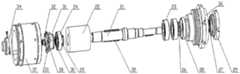
图2为本发明中槽道螺旋桨总成的爆炸图;Fig. 2 is an exploded view of the channel propeller assembly in the present invention;
图3为本发明中槽道螺旋桨总成与槽道推进器本体的安装示意图;Figure 3 is a schematic diagram of the installation of the channel propeller assembly and the channel propeller body in the present invention;
图4为本发明中传动轴系的爆炸图;Fig. 4 is the exploded diagram of drive shafting in the present invention;
图5为本发明中耐压壳体的爆炸图;Fig. 5 is an explosion diagram of a pressure-resistant housing in the present invention;
图中:1、槽道推进器本体;2、压力补偿器;3、槽道螺旋桨总成;4、桨叶;5、间隔套;6、桨毂;7、固定螺钉;8、平键;9、防松螺母;10、导流盖;11、导流盖螺钉;21、传动主轴;22、无框电机转子;23、角接触球轴承;24、深沟球轴承;25、转子固定挡圈;26、圆螺母;27、唇形密封圈;28、轴承间隙调整套;29、动密封端盖;30、弹性挡圈;31、旋转编码器定子;32、压紧螺母;33、压环;34、保护盖;35、电机平键;36、前轴承座;37、后轴承座;38、旋转编码器转子;40、接插件安装端盖;41、径向螺钉;42、无框电机定子;43、基座壳体;44、导流环;45、接插件;46、轴向螺钉。In the figure: 1. The channel propeller body; 2. Pressure compensator; 3. The channel propeller assembly; 4. Blade; 5. Spacer sleeve; 6. Propeller hub; 7. Fixing screw; 8. Flat key; 9. Lock nut; 10. Guide cover; 11. Guide cover screw; 21. Transmission main shaft; 22. Frameless motor rotor; 23. Angular contact ball bearing; 24. Deep groove ball bearing; 25. Rotor fixed stop ring; 26, round nut; 27, lip seal ring; 28, bearing gap adjustment sleeve; 29, dynamic seal end cover; 30, elastic retaining ring; 31, rotary encoder stator; 32, compression nut; 33, pressure Ring; 34, protective cover; 35, motor flat key; 36, front bearing seat; 37, rear bearing seat; 38, rotary encoder rotor; 40, connector installation end cover; 41, radial screw; 42, frameless Motor stator; 43. Base shell; 44. Guide ring; 45. Connector; 46. Axial screw.
具体实施方式Detailed ways
为了使本发明的目的、技术方案和优点更加清楚,下面结合附图和具体实施例对本发明进行详细描述。In order to make the object, technical solution and advantages of the present invention clearer, the present invention will be described in detail below in conjunction with the accompanying drawings and specific embodiments.
如图1所示,本发明提供一种深海自主水下机器人的槽道推进器,包括槽道推进器本体1和槽道螺旋桨总成3;槽道推进器本体1包括耐压壳体及设置于耐压壳体内的无框电机、传动轴系和旋转编码器,其中旋转编码器设置于传动轴系的末端,传动轴系的前端由耐压壳体穿出且与槽道螺旋桨总成3连接,无框电机与传动轴系连接,无框电机用于驱动传动轴系转动。As shown in Figure 1, the present invention provides a channel propeller for deep-sea autonomous underwater robots, including a
如图4所示,本发明的实施例中,传动轴系包括传动主轴21、前轴承座36及后轴承座37,其中前轴承座36和后轴承座37分别密封连接于耐压壳体的前、后端,传动主轴21的两端通过轴承安装在前轴承座36和后轴承座37内,槽道螺旋桨总成3连接在传动主轴21上。As shown in Figure 4, in the embodiment of the present invention, the transmission shaft system includes the transmission
本发明的实施例中,无框电机包括无框电机转子22和无框电机定子42,其中无框电机转子22通过电机平键35与传动主轴21连接,且通过转子固定挡圈25轴向固定,将无框电机的动力传递到传动主轴21上;无框电机定子42设置于耐压壳体的内壁上,且与无框电机转子22相对应。In the embodiment of the present invention, the frameless motor includes a
本发明的实施例中,旋转编码器包括旋转编码器定子31和旋转编码器转子38,其中旋转编码器定子31设置于后轴承座37内,且通过压环33固定;旋转编码器转子38设置于传动主轴21的末端,且通过压紧螺母32固定,旋转编码器转子38位于旋转编码器转子38内侧。In the embodiment of the present invention, the rotary encoder includes a
如图3-5所示,本发明的实施例中,耐压壳体包括基座壳体43、动密封端盖29和接插件安装端盖40,前轴承座36和后轴承座37分别设置于基座壳体43的两端,且通过O型密封圈密封,前轴承座36通过多个轴向螺钉46与基座壳体43连接。动密封端盖29固定连接在前轴承座36的外侧,动密封端盖29与传动主轴21之间通过唇形油封27密封,实现与传动主轴21的动密封;接插件安装端盖40固定连接在后轴承座37的外侧端部,且通过径向螺钉41与后轴承座37连接。接插件安装端盖40上设有接插件45。接插件45为水密接插件,用于槽道推进器的供电及信号检测。As shown in Figures 3-5, in the embodiment of the present invention, the pressure-resistant housing includes a
具体地,前轴承座36内设有两个角接触球轴承23,角接触球轴承23的内圈与传动主轴21连接,且内圈通过两个圆螺母26实现轴向定位和防松。角接触球轴承23的外圈通过轴承间隙调整套28和动密封端盖29固定。后轴承座37内设有深沟球轴承24,深沟球轴承24通过弹性挡圈30进行定位和固定;后轴承座37的外侧设有保护盖34,防止传动主轴21旋转时,旋转编码器定子31电缆被破坏。两个角接触球轴承23和深沟球轴承24为传动主轴21提供支撑。Specifically, two angular
如图2-3所示,本发明的实施例中,槽道螺旋桨总成3包括由外到内依次同轴连接的桨叶4、间隔套5及桨毂6,桨叶4、间隔套5及桨毂6通过多个固定螺钉7连接为一体,桨毂6通过平键8与传动主轴21连接,且通过两个防松螺母9锁紧,以便传递扭矩和动力。As shown in Figures 2-3, in the embodiment of the present invention, the channeled
进一步地,槽道推进器本体1与槽道螺旋桨总成3之间设有导流环44。槽道螺旋桨总成3的外侧端安装有导流盖10,导流盖10通过多个导流盖螺钉11与桨叶4连接。导流盖10的作用是槽道螺旋桨总成3正、反向旋转时,提高流场的整流能力,推进效果显著。Further, a
在上述实施例的基础上,本发明提供的一种深海自主水下机器人的槽道推进器,还包括压力补偿器2,压力补偿器2设置于槽道推进器本体1远离槽道螺旋桨总成3的一端,使槽道推进器的内部冲满绝缘油液,使其内部压力大于外界环境的压力,适应深海环境的压力,压力补偿器2的压力补偿技术为现有技术,在此不再赘述。On the basis of the above embodiments, the present invention provides a channel propeller for a deep-sea autonomous underwater robot, which also includes a
本发明的实施例中,通过设置压力补偿器使槽道推进器的内部压力大于外界环境的压力,适应深海的工作压力环境。螺旋桨总成在槽道推进器无框电机的驱动下,正反转旋转推动流体而获得相应的推进力。同时,槽道推进器设置旋转编码器检测转动角度,控制电路根据旋转编码器的角度信息能精确的控制和保持推进器的转速,为自主水下机器人提供上浮、下潜时反抗环境条件的高精度的控制力或力矩,从而实现自主水下机器人的升沉运动。本发明的槽道推进器具有结构简单、反应迅速、效率高、噪声小、便于安装和维护等优点。In the embodiment of the present invention, by setting a pressure compensator, the internal pressure of the channel propeller is greater than the pressure of the external environment, so as to adapt to the working pressure environment of deep sea. Driven by the frameless motor of the channel propeller, the propeller assembly rotates forward and reverse to push the fluid to obtain the corresponding propulsion. At the same time, the slot propeller is equipped with a rotary encoder to detect the rotation angle, and the control circuit can accurately control and maintain the speed of the propeller according to the angle information of the rotary encoder, providing autonomous underwater robots with high resistance to environmental conditions when they float up and dive. Accurate control of force or moment, so as to realize the heave motion of the autonomous underwater robot. The channel thruster of the invention has the advantages of simple structure, rapid response, high efficiency, low noise, easy installation and maintenance, and the like.
以上所述仅为本发明的实施方式,并非用于限定本发明的保护范围。凡在本发明的精神和原则之内所作的任何修改、等同替换、改进、扩展等,均包含在本发明的保护范围内。The above description is only an implementation manner of the present invention, and is not intended to limit the protection scope of the present invention. Any modifications, equivalent replacements, improvements, extensions, etc. made within the spirit and principles of the present invention are included in the protection scope of the present invention.
Claims (6)
Priority Applications (1)
| Application Number | Priority Date | Filing Date | Title |
|---|---|---|---|
| CN202210632481.2ACN114889794B (en) | 2022-06-06 | 2022-06-06 | A channel thruster for deep-sea autonomous underwater robot |
Applications Claiming Priority (1)
| Application Number | Priority Date | Filing Date | Title |
|---|---|---|---|
| CN202210632481.2ACN114889794B (en) | 2022-06-06 | 2022-06-06 | A channel thruster for deep-sea autonomous underwater robot |
Publications (2)
| Publication Number | Publication Date |
|---|---|
| CN114889794A CN114889794A (en) | 2022-08-12 |
| CN114889794Btrue CN114889794B (en) | 2023-06-20 |
Family
ID=82727589
Family Applications (1)
| Application Number | Title | Priority Date | Filing Date |
|---|---|---|---|
| CN202210632481.2AActiveCN114889794B (en) | 2022-06-06 | 2022-06-06 | A channel thruster for deep-sea autonomous underwater robot |
Country Status (1)
| Country | Link |
|---|---|
| CN (1) | CN114889794B (en) |
Families Citing this family (1)
| Publication number | Priority date | Publication date | Assignee | Title |
|---|---|---|---|---|
| CN118080901B (en)* | 2024-04-22 | 2024-07-05 | 山东豪迈数控机床有限公司 | Lathe spindle |
Family Cites Families (10)
| Publication number | Priority date | Publication date | Assignee | Title |
|---|---|---|---|---|
| CN104085519B (en)* | 2014-07-14 | 2016-11-23 | 中国船舶重工集团公司第七○二研究所 | Contrarotating conduit propeller |
| CN105346696B (en)* | 2015-11-19 | 2016-09-14 | 浙江大学 | Integrated contra-rotating propeller |
| CN206615377U (en)* | 2017-04-18 | 2017-11-07 | 深圳市吉影科技有限公司 | A kind of underwater propeller and underwater robot |
| CN207417102U (en)* | 2017-11-03 | 2018-05-29 | 合肥倍豪海洋装备技术有限公司 | A kind of new rudder angle feedback device |
| CN110816795B (en)* | 2019-11-29 | 2021-03-16 | 吉林大学 | An unmanned submersible with multiple degrees of freedom |
| CN111874195B (en)* | 2020-08-11 | 2024-08-16 | 中国科学院沈阳自动化研究所 | Autonomous underwater robot structure at full sea depth and offshore bottom |
| CN112623174B (en)* | 2020-12-25 | 2024-12-13 | 北京航空航天大学合肥创新研究院 | A tail-mounted electric propeller with fly-by-wire control |
| CN112737255B (en)* | 2020-12-25 | 2022-04-05 | 中国科学院宁波材料技术与工程研究所 | Disc type double-rotor counter-rotating motor and aircraft |
| CN113581438A (en)* | 2021-08-27 | 2021-11-02 | 中国船舶科学研究中心 | Integrated deep sea integrated electric propeller |
| CN113937954A (en)* | 2021-10-20 | 2022-01-14 | 深圳市德创水下智能装备有限公司 | A new type of underwater propeller |
- 2022
- 2022-06-06CNCN202210632481.2Apatent/CN114889794B/enactiveActive
Also Published As
| Publication number | Publication date |
|---|---|
| CN114889794A (en) | 2022-08-12 |
Similar Documents
| Publication | Publication Date | Title |
|---|---|---|
| CN103818535A (en) | Integrated motor propelling device | |
| CN202923877U (en) | Small-size underwater magnetic coupling propeller device | |
| CN101716768A (en) | Integrated driving joint of underwater operation system | |
| CN110861453B (en) | Trans-medium water-air propulsion device with variable output torque and pitch | |
| CN101508336B (en) | Underwater Tail rudder steering module and submerged vessels containing the same | |
| CN207983397U (en) | Underwater electric joint structure with position and speed feedback | |
| CN114889794B (en) | A channel thruster for deep-sea autonomous underwater robot | |
| CN109703728A (en) | A magnetic coupling steering device for deep-sea autonomous underwater vehicle | |
| CN111377047B (en) | Magnetic transmission pressure compensation efficient propulsion device for underwater robot | |
| CN205150207U (en) | Integrated propeller of boats and ships rim | |
| CN202046433U (en) | Small-sized oil-filled full-deflection vector propeller | |
| CN112406434B (en) | Electric water-air dual-purpose propeller | |
| CN210653605U (en) | Novel underwater brushless magnetic coupling propeller | |
| CN111532414A (en) | Static sealing structure of propeller rotating shaft of underwater vehicle | |
| CN114933005A (en) | A deep-sea autonomous underwater robot self-locking steering gear | |
| CN116533694B (en) | A dual-mode magnetic coupling thruster based on planetary gears | |
| CN214729616U (en) | Single-piston electro-hydraulic servo constant-speed variable-pitch propeller mechanism | |
| CN110254675A (en) | Ship's adjustable pitch propeller and its electric control pitch adjustment mechanism | |
| CN101973381A (en) | Propeller shaft seal installation structure of full-rotation steering oar | |
| CN210618431U (en) | Permanent magnet motor co-rotating pod propeller | |
| CN209351578U (en) | High-efficiency propulsion device with magnetic drive pressure compensation for underwater robots | |
| CN110125973B (en) | Underwater electric joint structure with position and speed feedback | |
| CN111516822A (en) | A miniaturized full gyration propeller for boats and ships dynamic positioning model test | |
| CN101936380A (en) | Magnetic Drive Leakproof Envelope | |
| CN216734461U (en) | Magnetorheological rotary damper, electric power steering system and motor vehicle |
Legal Events
| Date | Code | Title | Description |
|---|---|---|---|
| PB01 | Publication | ||
| PB01 | Publication | ||
| SE01 | Entry into force of request for substantive examination | ||
| SE01 | Entry into force of request for substantive examination | ||
| GR01 | Patent grant | ||
| GR01 | Patent grant |