CN114889783A - Pure oxygen type closed circulation respiratory - Google Patents
Pure oxygen type closed circulation respiratoryDownload PDFInfo
- Publication number
- CN114889783A CN114889783ACN202210583166.5ACN202210583166ACN114889783ACN 114889783 ACN114889783 ACN 114889783ACN 202210583166 ACN202210583166 ACN 202210583166ACN 114889783 ACN114889783 ACN 114889783A
- Authority
- CN
- China
- Prior art keywords
- breathing
- pure oxygen
- lung bag
- oxygen
- tank
- Prior art date
- Legal status (The legal status is an assumption and is not a legal conclusion. Google has not performed a legal analysis and makes no representation as to the accuracy of the status listed.)
- Pending
Links
- MYMOFIZGZYHOMD-UHFFFAOYSA-NDioxygenChemical compoundO=OMYMOFIZGZYHOMD-UHFFFAOYSA-N0.000titleclaimsabstractdescription41
- 230000000241respiratory effectEffects0.000titleclaims5
- 230000029058respiratory gaseous exchangeEffects0.000claimsabstractdescription89
- 210000004072lungAnatomy0.000claimsabstractdescription63
- 239000007789gasSubstances0.000claimsabstractdescription46
- 229910052760oxygenInorganic materials0.000claimsabstractdescription39
- 239000001301oxygenSubstances0.000claimsabstractdescription39
- QVGXLLKOCUKJST-UHFFFAOYSA-Natomic oxygenChemical compound[O]QVGXLLKOCUKJST-UHFFFAOYSA-N0.000claimsabstractdescription38
- 239000003463adsorbentSubstances0.000claimsabstractdescription31
- CURLTUGMZLYLDI-UHFFFAOYSA-NCarbon dioxideChemical compoundO=C=OCURLTUGMZLYLDI-UHFFFAOYSA-N0.000claimsabstractdescription30
- 229910002092carbon dioxideInorganic materials0.000claimsabstractdescription15
- 239000001569carbon dioxideSubstances0.000claimsabstractdescription15
- 238000012544monitoring processMethods0.000claimsdescription3
- 210000002345respiratory systemAnatomy0.000claims5
- 230000009189divingEffects0.000abstractdescription15
- 238000013461designMethods0.000abstractdescription6
- 230000007774longtermEffects0.000abstractdescription3
- 239000002184metalSubstances0.000description16
- 238000007789sealingMethods0.000description16
- 238000006243chemical reactionMethods0.000description11
- 238000009434installationMethods0.000description11
- 238000010586diagramMethods0.000description8
- 238000009423ventilationMethods0.000description8
- 230000007246mechanismEffects0.000description6
- 230000000903blocking effectEffects0.000description4
- 239000012528membraneSubstances0.000description4
- 238000000034methodMethods0.000description4
- 238000004891communicationMethods0.000description2
- 230000000694effectsEffects0.000description2
- 230000008557oxygen metabolismEffects0.000description2
- 230000008569processEffects0.000description2
- 238000004064recyclingMethods0.000description2
- 239000002594sorbentSubstances0.000description2
- 238000001179sorption measurementMethods0.000description2
- 239000002699waste materialSubstances0.000description2
- 229920000049Carbon (fiber)Polymers0.000description1
- 230000009286beneficial effectEffects0.000description1
- 239000004917carbon fiberSubstances0.000description1
- 239000003795chemical substances by applicationSubstances0.000description1
- 239000003365glass fiberSubstances0.000description1
- 239000000463materialSubstances0.000description1
- 230000004060metabolic processEffects0.000description1
- VNWKTOKETHGBQD-UHFFFAOYSA-NmethaneChemical compoundCVNWKTOKETHGBQD-UHFFFAOYSA-N0.000description1
- 238000012986modificationMethods0.000description1
- 230000004048modificationEffects0.000description1
- 230000003204osmotic effectEffects0.000description1
- 239000007779soft materialSubstances0.000description1
Images


Classifications
- B—PERFORMING OPERATIONS; TRANSPORTING
- B63—SHIPS OR OTHER WATERBORNE VESSELS; RELATED EQUIPMENT
- B63C—LAUNCHING, HAULING-OUT, OR DRY-DOCKING OF VESSELS; LIFE-SAVING IN WATER; EQUIPMENT FOR DWELLING OR WORKING UNDER WATER; MEANS FOR SALVAGING OR SEARCHING FOR UNDERWATER OBJECTS
- B63C11/00—Equipment for dwelling or working underwater; Means for searching for underwater objects
- B63C11/02—Divers' equipment
- B63C11/18—Air supply
- B63C11/22—Air supply carried by diver
- B63C11/24—Air supply carried by diver in closed circulation
- B—PERFORMING OPERATIONS; TRANSPORTING
- B63—SHIPS OR OTHER WATERBORNE VESSELS; RELATED EQUIPMENT
- B63C—LAUNCHING, HAULING-OUT, OR DRY-DOCKING OF VESSELS; LIFE-SAVING IN WATER; EQUIPMENT FOR DWELLING OR WORKING UNDER WATER; MEANS FOR SALVAGING OR SEARCHING FOR UNDERWATER OBJECTS
- B63C11/00—Equipment for dwelling or working underwater; Means for searching for underwater objects
- B63C11/02—Divers' equipment
- B63C2011/026—Diving harnesses, or the like, e.g. for carrying breathing air tanks
- Y—GENERAL TAGGING OF NEW TECHNOLOGICAL DEVELOPMENTS; GENERAL TAGGING OF CROSS-SECTIONAL TECHNOLOGIES SPANNING OVER SEVERAL SECTIONS OF THE IPC; TECHNICAL SUBJECTS COVERED BY FORMER USPC CROSS-REFERENCE ART COLLECTIONS [XRACs] AND DIGESTS
- Y02—TECHNOLOGIES OR APPLICATIONS FOR MITIGATION OR ADAPTATION AGAINST CLIMATE CHANGE
- Y02C—CAPTURE, STORAGE, SEQUESTRATION OR DISPOSAL OF GREENHOUSE GASES [GHG]
- Y02C20/00—Capture or disposal of greenhouse gases
- Y02C20/40—Capture or disposal of greenhouse gases of CO2
Landscapes
- Health & Medical Sciences (AREA)
- General Health & Medical Sciences (AREA)
- Pulmonology (AREA)
- Engineering & Computer Science (AREA)
- Mechanical Engineering (AREA)
- Ocean & Marine Engineering (AREA)
- Respiratory Apparatuses And Protective Means (AREA)
Abstract
Translated fromChinese
Description
Translated fromChinese技术领域technical field
本发明涉及潜水领域,特别是涉及一种纯氧型密闭式循环呼吸系统。The invention relates to the diving field, in particular to a pure oxygen type closed recirculation breathing system.
背景技术Background technique
密闭式循环呼吸系统,简称CCR,是一种潜水时使用的呼吸装置。以往的开放式水肺潜水,空气在人体氧代谢后直接排气到海里,而氧代谢过程中只用了气体内约5-6%的氧气,其余氧气连同代谢的二氧化碳一起排放出去,这就造成在潜水时氧气浪费,缩短潜水时间。A closed circuit rebreathing system, or CCR for short, is a breathing apparatus used during diving. In the past open scuba diving, the air was directly exhausted into the sea after the human body's oxygen metabolism, but only about 5-6% of the oxygen in the gas was used in the oxygen metabolism process, and the rest of the oxygen was discharged together with the metabolized carbon dioxide. Causes a waste of oxygen during diving and shortens the diving time.
因此,现在亟需设计一种能解决上述一个或者多个问题的纯氧型密闭式循环呼吸系统。Therefore, there is an urgent need to design a pure oxygen type closed respiration system that can solve one or more of the above problems.
发明内容SUMMARY OF THE INVENTION
为解决现有技术中存在的一个或者多个问题,本发明提供了一种纯氧型密闭式循环呼吸系统。In order to solve one or more problems existing in the prior art, the present invention provides a pure oxygen type closed circulatory breathing system.
本发明为达到上述目的所采用的技术方案是:一种纯氧型密闭式循环呼吸系统,所述纯氧型密闭式循环呼吸系统包括:The technical scheme adopted by the present invention to achieve the above purpose is: a pure oxygen type closed circulatory breathing system, the pure oxygen type closed circulatory breathing system comprises:
设有呼吸管道的箱体,所述呼吸管道为单向管道;A box body provided with a breathing pipe, the breathing pipe is a one-way pipe;
能够将呼出气体循环利用的循环呼吸装置,所述循环呼吸装置固定在所述箱体内,所述循环呼吸装置包括与所述呼吸管道一端相连的第一肺袋,与所述呼吸管道另一端相连的第二肺袋,及分别与所述第一肺袋和所述第二肺袋相连接的吸附剂罐,所述吸附剂罐用于吸附呼出气体中的二氧化碳;以及A circulatory breathing device capable of recycling exhaled gas, the circulatory breathing device is fixed in the box, and the circulatory breathing device includes a first lung bag connected to one end of the breathing pipe and connected to the other end of the breathing pipe a second lung bag, and an adsorbent canister connected to the first lung bag and the second lung bag respectively, the adsorbent canister is used to adsorb carbon dioxide in exhaled air; and
能够提供纯氧的纯氧装置,所述纯氧装置固定在所述箱体外侧,所述纯氧装置包括装设有氧气的氧气罐,及与所述氧气罐相连的自动加气阀,所述自动加气阀与所述第一肺袋相连。A pure oxygen device capable of providing pure oxygen, the pure oxygen device is fixed on the outside of the box, the pure oxygen device includes an oxygen tank equipped with oxygen, and an automatic gas filling valve connected with the oxygen tank, so The automatic filling valve is connected to the first lung bag.
在一些实施例里,所述呼吸管道上设有呼吸转换阀,用于使气体在所述呼吸管道上单向运动,所述呼吸转换阀上设有呼吸嘴。In some embodiments, a respiration conversion valve is provided on the breathing pipe to make the gas move in one direction on the breathing pipe, and a breathing mouth is provided on the breathing conversion valve.
在一些实施例里,所述吸附剂罐内设有二氧化碳吸附剂。In some embodiments, the adsorbent tank is provided with a carbon dioxide adsorbent.
在一些实施例里,所述氧气罐连接有气压表,用于监测罐内气体压力。In some embodiments, the oxygen tank is connected with a barometer for monitoring the gas pressure in the tank.
在一些实施例里,所述循环呼吸装置还包括快拆连接件,所述吸附剂罐与所述第一肺袋和所述第二肺袋通过所述快拆连接件连接。In some embodiments, the rebreather device further includes a quick-release connector, and the sorbent canister is connected to the first lung bag and the second lung bag through the quick-release connector.
在一些实施例里,所述呼吸管道与所述第一肺袋和所述第二肺袋通过所述快拆连接件连接,所述自动加气阀与所述第一肺袋通过也通过所述快拆连接件连接。In some embodiments, the breathing tube is connected to the first lung bag and the second lung bag through the quick release connector, and the automatic refill valve is connected to the first lung bag through and through the The quick release connector is connected.
本发明的有益效果是:相较于现有技术,本发明包括:设有呼吸管道的箱体,所述呼吸管道为单向管道;能够将呼出气体循环利用的循环呼吸装置,所述循环呼吸装置固定在所述箱体内,所述循环呼吸装置包括与所述呼吸管道一端相连的第一肺袋,与所述呼吸管道另一端相连的第二肺袋,及分别与所述第一肺袋和所述第二肺袋相连接的吸附剂罐,所述吸附剂罐用于吸附呼出气体中的二氧化碳;以及能够提供纯氧的纯氧装置,所述纯氧装置固定在所述箱体外侧,所述纯氧装置包括装设有氧气的氧气罐,及与所述氧气罐相连的自动加气阀,所述自动加气阀与所述第一肺袋相连。采用上述设计,使得本发明能够循环利用氧气,能够在下潜不超过6m的深度时使用且能够保持长时间潜水。The beneficial effects of the present invention are: compared with the prior art, the present invention includes: a box body provided with a breathing pipe, and the breathing pipe is a one-way pipe; The device is fixed in the box, and the circulatory breathing device includes a first lung bag connected with one end of the breathing pipe, a second lung bag connected with the other end of the breathing pipe, and the first lung bag respectively. an adsorbent tank connected to the second lung bag, the adsorbent tank is used for adsorbing carbon dioxide in exhaled air; and a pure oxygen device capable of providing pure oxygen, the pure oxygen device is fixed outside the box body , the pure oxygen device includes an oxygen tank equipped with oxygen, and an automatic gas filling valve connected with the oxygen tank, and the automatic gas filling valve is connected with the first lung bag. By adopting the above design, the present invention can recycle oxygen, can be used when diving to a depth of not more than 6m, and can maintain long-term diving.
附图说明Description of drawings
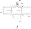
图1为本发明较佳实施例的结构示意图;1 is a schematic structural diagram of a preferred embodiment of the present invention;
图2为本发明较佳实施例内部的结构示意图;Fig. 2 is the structural representation inside the preferred embodiment of the present invention;
图3为本发明较佳实施例呼吸转换阀的结构示意图;3 is a schematic structural diagram of a breathing conversion valve according to a preferred embodiment of the present invention;
图4为本发明较佳实施例呼吸转换阀的剖面图;4 is a cross-sectional view of a breathing switching valve according to a preferred embodiment of the present invention;
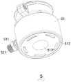
图5为本发明较佳实施例自动加气阀的结构示意图;5 is a schematic structural diagram of an automatic gas filling valve according to a preferred embodiment of the present invention;
图6为本发明较佳实施例自动加气阀的剖面图;6 is a cross-sectional view of an automatic gas filling valve according to a preferred embodiment of the present invention;
图7为本发明较佳实施例加气阀的结构示意图;7 is a schematic structural diagram of a gas filling valve according to a preferred embodiment of the present invention;
图8为本发明较佳实施例加气阀的爆炸图;FIG. 8 is an exploded view of a gas filling valve according to a preferred embodiment of the present invention;
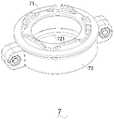
图9为本发明较佳实施例快拆连接件的结构示意图;9 is a schematic structural diagram of a quick-release connector according to a preferred embodiment of the present invention;
图10为本发明较佳实施例快拆连接件的爆炸图;Figure 10 is an exploded view of the quick-release connector according to the preferred embodiment of the present invention;
图11为本发明较佳实施例吸附剂罐的剖面图;11 is a cross-sectional view of an adsorbent tank of a preferred embodiment of the present invention;
图12为本发明较佳实施例卡扣结构的结构示意图;12 is a schematic structural diagram of a buckle structure according to a preferred embodiment of the present invention;
图13为本发明较佳实施例拉簧的结构示意图;FIG. 13 is a schematic structural diagram of a tension spring according to a preferred embodiment of the present invention;
图14为本发明较佳实施例右卡钩脱离拉簧孔的状态示意图。FIG. 14 is a schematic diagram of the state in which the right hook is separated from the tension spring hole according to the preferred embodiment of the present invention.
图中:In the picture:
1-箱体;11-呼吸管道;12-呼吸转换阀;121-主壳体;122-转动壳体;123-转动件;124-呼吸嘴;1211-助力件;1-box body; 11-breathing pipe; 12-breathing conversion valve; 121-main housing; 122-rotating housing; 123-rotating part; 124-breathing mouth; 1211-assisting part;
2-氧气罐;2- Oxygen tank;
5-自动加气阀;51-自动阀体;511-阀体管;512-底盖;513-按压壳;514-气体通道;5141-第一环形凸体;52-加气阀;521-第一连接管;522-第二连接管;5221-出气孔;5222-缺口;523-密封件;5231-过气孔;524-活塞杆机构;5241-活塞杆;5242-加气阀安装座;5243-密封垫;5244-弹簧;5245-第一安装套;5246-第二安装套;5247-螺帽;54-按压件;5-automatic filling valve; 51-automatic valve body; 511-valve body pipe; 512-bottom cover; 513-pressing shell; 514-gas passage; 5141-first annular convex body; 522-second connecting pipe; 5221-air outlet; 5222-notch; 523-seal; 5231-air hole; 524-piston rod mechanism; 5241-piston rod; 5242-air filling valve mounting seat; 5243-gasket; 5244-spring; 5245-first installation sleeve; 5246-second installation sleeve; 5247-nut; 54-pressing piece;
6-第一肺袋;6 - the first lung bag;
7-快拆连接件;71-安装圈;72-固定圈;721-第三环形凸体;722-第二定位凸体;7-Quick release connector; 71-Installation ring; 72-Fixing ring; 721-Third annular convex body; 722-Second positioning convex body;
8-吸附剂罐;81-罐体;811-第一金属件;812-第二金属件;82-第一连接件;83-第二连接件;831-第一卡扣槽;832-卡扣通孔;84-顶盖;841-第二卡扣槽;842-环形密封槽;85-卡扣条;851-卡扣凸体;852-拉簧孔;86-拉簧;861-左卡钩;862-左拉簧;863-右卡钩;864-右拉簧;865-连接条;87-拉绳;88-第一密封圈。8-sorbent tank; 81-tank body; 811-first metal piece; 812-second metal piece; 82-first connecting piece; 83-second connecting piece; 831-first snap groove; 832-card Buckle through hole; 84-top cover; 841-second buckle groove; 842-ring sealing groove; 85-buckle strip; 851-buckle protrusion; 852-tension spring hole; 86-tension spring; 861-left Hook; 862-left tension spring; 863-right hook; 864-right tension spring; 865-connecting strip; 87-pull rope; 88-first sealing ring.
具体实施方式Detailed ways
为使本发明的上述目的、特征和优点能够更加浅显易懂,下面结合附图对本发明的具体实施方式做详细的说明。在下面的描述中阐述了很多具体细节以便于充分理解本发明。但是本发明能够以很多不同于在此描述的其它方式来实施,本领域技术人员可以在不违背本发明内涵的情况下做类似改进,因此本发明不受下面公开的具体实施例的限制。In order to make the above objects, features and advantages of the present invention easier to understand, the specific embodiments of the present invention will be described in detail below with reference to the accompanying drawings. In the following description, numerous specific details are set forth in order to provide a thorough understanding of the present invention. However, the present invention can be implemented in many other ways different from those described herein, and those skilled in the art can make similar improvements without departing from the connotation of the present invention. Therefore, the present invention is not limited by the specific embodiments disclosed below.
如图1-图14所示,本发明提出一种纯氧型密闭式循环呼吸系统,所述纯氧型密闭式循环呼吸系统包括:As shown in FIG. 1-FIG. 14, the present invention proposes a pure oxygen type closed circulatory breathing system, and the pure oxygen type closed circulatory breathing system includes:
设有呼吸管道11的箱体1,所述呼吸管道11为单向管道;The
能够将呼出气体循环利用的循环呼吸装置,所述循环呼吸装置固定在所述箱体1内,所述循环呼吸装置包括与所述呼吸管道11一端相连的第一肺袋6,与所述呼吸管道11另一端相连的第二肺袋,及分别与所述第一肺袋6和所述第二肺袋相连接的吸附剂罐8,所述吸附剂罐8用于吸附呼出气体中的二氧化碳;以及A circulatory breathing device capable of recycling exhaled gas, the circulatory breathing device is fixed in the
能够提供纯氧的纯氧装置,所述纯氧装置固定在所述箱体1外侧,所述纯氧装置包括装设有氧气的氧气罐2,及与所述氧气罐2相连的自动加气阀5,所述自动加气阀5与所述第一肺袋6相连。A pure oxygen device capable of providing pure oxygen, the pure oxygen device is fixed on the outside of the
具体的,使用本实施例潜水时,人体通过所述呼吸管道11呼吸,吸气时,所述第二肺袋的氧气进入所述呼吸管道11的一端并被人体吸入,呼气时,人体将代谢产生的二氧化碳和剩余氧气呼出在所述呼吸管道11的另一端,且由于所述呼吸管道11为单向管道,因此呼出的气体不能进入所述第二肺袋内,只能进入所述第一肺袋6内,然后经过所述吸附剂罐8内的二氧化碳吸附剂作用,将呼出气体的二氧化碳吸附,剩余的氧气进入所述第二肺袋内,供人体吸入。这样可以使得呼出气体内的氧气被循环利用,避免浪费,本实施例体积可以设置的很小,由于氧气的充分利用,却可以供人体长时间潜水,且由于是通过所述呼吸管道11呼吸,气体不排出在海里,因此不会产生气泡,所以本实施例适合作战系统,尤其是渗透作战。Specifically, when diving using this embodiment, the human body breathes through the
当所述第一肺袋6和所述第二肺袋内的氧气不够时,所述自动吸气阀5会自动打开,使得所述氧气罐2内的氧气自动进入所述第一肺袋6内,由此可知,所述纯氧装置能够提供纯氧,以适应使用者的潜水需求。需要说明的是,氧气罐2上安装有减压阀,气体减压后再经过自动加气阀5进入第一肺袋6内,但由于该减压手段为本技术领域的常规手段,因此不再赘述。When the oxygen in the
在本实施例里,所述自动加气阀5包括:底部设有按压壳513的自动阀体51,所述按压壳513有弹性,所述自动阀体51侧壁上设有与其内部相通的阀体管511;以及能够自动打开的加气阀52,所述加气阀52从所述阀体管511伸入所述自动阀体51内,并与所述阀体管511螺纹连接,所述加气阀52伸入所述自动阀体51内的一端设有按压件54,按压所述按压壳513或所述自动阀体51内形成负压时,能够对所述按压件54进行按压,并通过所述按压件54将所述加气阀52打开。所述自动阀体51底部设有与其螺纹连接的底盖512,所述底盖512的中心位置设有与所述按压壳513相配合的按压孔421,所述底盖512将所述按压壳513固定在所述自动阀体51底部内,所述自动阀体51顶端设有气体通道514,所述气体通道514外侧设有第一环形凸体5141。所述阀体管511内壁上设有内螺纹,外壁上设有外螺纹。In this embodiment, the automatic
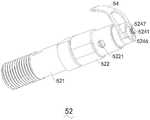
所述加气阀52包括:左端与所述阀体管511螺纹连接的第一连接管521;与所述第一连接管521的右端螺纹连接的第二连接管522,所述第二连接管522上设有出气孔5221;设有过气孔5231的的密封件523,所述密封件523右端与所述第二连接管522螺纹连接,左端伸入所述第一连接管521内并做密封处理,使气体只能从所述过气孔5231穿过;以及设置在所述第二连接管522内的活塞杆机构524,所述活塞杆机构524能够挡住或放开所述过气孔5231,所述按压件54与所述活塞杆机构524的右端卡扣连接。所述第二连接管522右端的侧壁上设有两个与所述按压件54相配合的缺口5222,所述第二连接管522右端内还设有与所述活塞杆机构524相配合的第二环形凸体4541。The
所述活塞杆机构524包括:“┣”型的活塞杆5241,所述活塞杆5241的右端设有螺纹;与所述活塞杆5241左端连接的加气阀安装座5242,所述加气阀安装座5242上设有与所述活塞杆5241相配合的安装孔;固定在所述加气阀安装座5242内的密封垫5243,所述密封垫5243处于所述活塞杆5241的左方;套设在所述活塞杆5241上的第一安装套5245,所述第一安装套5245与所述第二环形凸体4541相配合;套设在所述活塞杆5241上的第二安装套5246,所述第二安装套5246处于所述第一安装套5245的右方,所述按压件54从所述缺口5222插入所述第一安装套5245和所述第二安装套5246之间;与所述活塞杆5241螺纹连接的螺帽5247,所述螺帽5247处于所述第二安装套5246的右方;以及套设在所述活塞杆5241上的弹簧5244,所述弹簧5244处于所述加气阀安装座5242和所述第二环形凸体4541之间,所述弹簧5244分别对所述加气阀安装座5242和所述第二环形凸体4541有一个弹力作用。所述按压件54为“Y”字形,且所述按压件54为弧形状,其一端插入所述缺口5222内,另一端朝向所述按压壳513。The piston rod mechanism 524 includes: a "┣" type piston rod 5241, the right end of the piston rod 5241 is provided with threads; a gas filling valve mounting seat 5242 connected with the left end of the piston rod 5241, the gas filling valve is installed The seat 5242 is provided with a mounting hole matched with the piston rod 5241; a gasket 5243 is fixed in the gas filling valve mounting seat 5242, and the gasket 5243 is located on the left side of the piston rod 5241; The first installation sleeve 5245 on the piston rod 5241, the first installation sleeve 5245 is matched with the second annular convex body 4541; the second installation sleeve 5246 sleeved on the piston rod 5241, so The second installation sleeve 5246 is located to the right of the first installation sleeve 5245, and the pressing member 54 is inserted between the first installation sleeve 5245 and the second installation sleeve 5246 from the notch 5222; A nut 5247 to which the piston rod 5241 is threaded, the nut 5247 is located on the right side of the second installation sleeve 5246; and a spring 5244 sleeved on the piston rod 5241, the spring 5244 is in the air Between the valve mounting seat 5242 and the second annular convex body 4541 , the spring 5244 has an elastic force on the gas filling valve mounting seat 5242 and the second annular convex body 4541 respectively. The pressing
所述阀体管511与所述第一肺袋6连接,当所述第一肺袋6内形成负压时,所述所述自动加气阀5内也处于负压状态,此时所述按压壳513会发生变形、被吸向所述按压件54,从而将所述按压件54的一端进行按压,所述按压件54一端被按压后,另一端会翘起,从而将所述加气阀52的通道打开,使得气体能够经过所述加气阀52进入所述第一肺袋6内;或是按压所述按压壳513时,通过所述按压壳513将所述按压件54一端进行按压,使所述按压件54另一端翘起,同样能够实现打开所述加气阀52的作用。The
在一些实施例中,所述呼吸管道11上设有呼吸转换阀12,用于使气体在所述呼吸管道11上单向运动,所述呼吸转换阀12上设有呼吸嘴124。In some embodiments, the
具体的,本实施例的呼吸转换阀12包括:主壳体121,所述主壳体121内设置有换气腔,所述主壳体121上设置有通气孔和呼吸限位槽;呼吸嘴124,所述呼吸嘴124设置在所述主壳体121上,所述呼吸嘴124上设置有第一呼吸口,所述第一呼吸口与所述换气腔连通;转动部,所述转动部包括转动壳体122和转动件123,所述转动壳体122上设置有连通槽和第二呼吸口,所述转动件123与所述转动壳体122固定连接,所述转动件123呈手柄状,所述转动壳体122与所述换气腔间隙配合,所述转动件123能够沿所述呼吸限位槽相对于所述主壳体121定轴转动,所述第一呼吸口通过所述转动件123,能够与所述第二呼吸口连通,或者,同时与所述连通槽、所述通气孔连通。Specifically, the
所述主壳体121还包括助力件1211,所述助力件1211设置在所述呼吸限位槽沿所述转动件123的转动方向的两侧,用于辅助使用者对所述转动件123施加作用力。本实施例的呼吸转换阀12还包括第一透气膜和第一阻挡件,所述主壳体121或所述转动壳体122上还设置有进气口,所述进气口与所述换气腔连通,所述进气口用于使空气通入所述换气腔,所述第一透气膜和第一阻挡件沿所述空气流动方向依次安装在所述进气口处。The
本实施例的呼吸转换阀12还包括第二透气膜和第二阻挡件,所述主壳体121或所述转动壳体122上还设置有出气口,所述出气口与所述换气腔连通,所述出气口用于使呼出的气体排出所述换气腔,所述第二透气膜和所述第二阻挡件沿呼出的气体流动方向依次安装在所述出气口处,所述主壳体121设置有第一标识,所述转动壳体122设置有第二标识,所述第一标识与所述第二标识之间存在差别。The
本实施例的呼吸转换阀12还包括咬合套,所述咬合套可拆卸地套接在所述呼吸嘴124上,所述咬合套采用软性材料制成。The
采用上述设计,人们在使用本实施例时,通过所述呼吸嘴124呼吸,氧气从所述第二肺袋出来,进入所述呼吸管道11的一端,经过所述呼吸转换阀12时被人体吸入,人体呼出时,呼出的气体进入所述呼吸转换阀12,进入所述呼吸管道11连接所述第一肺袋6的另一端,继而进入所述第一肺袋6,且不能返回进入所述第二肺袋内。这样单向运动的设计,避免了呼出气体没有经过吸附就进入所述第二肺袋。With the above design, when people use this embodiment, they breathe through the
在一些实施例中,所述吸附剂罐8内设有二氧化碳吸附剂。In some embodiments, the
具体的,因为本实施例是用于潜水,因此其对密封性能、防水性能的要求极高,尤其是所述吸附剂罐8内设有二氧化碳吸附剂,为了避免吸附作用失效,需保证二氧化碳吸附剂处于密封状态。吸附剂罐8通常是碳纤维或玻璃纤维材质,这样的材质不易打孔,因此与其他部件连接时密封性较差,尤其是吸附剂罐8的盖子部分,采用常规的螺旋连接方式的话,不便于做密封处理,且即使做了密封处理,密封效果也会较差。Specifically, because this embodiment is used for diving, it has extremely high requirements on sealing performance and waterproof performance. In particular, the
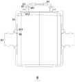
在本实施例里,所述吸附剂罐8包括:罐体81,所述罐体81的侧壁上一体成型有第一金属件811,所述罐体81的顶端一体成型有第二金属件812;第一连接件82,所述第一连接件82与所述第一金属件811固定连接;第二连接件83,所述第二连接件83与所述第二金属件812固定连接,所述第二连接件83的侧壁上设有第一卡扣槽831,所述第一卡扣槽831上设有卡扣通孔832;顶盖84,所述顶盖84与所述第二连接件83可拆卸连接,所述顶盖84的侧壁上设有第二卡扣槽841,所述第二卡扣槽841与所述卡扣通孔832相配合;以及卡扣结构,所述卡扣结构设置在所述第一卡扣槽831上,并卡进所述第二卡扣槽841内,用于使所述顶盖84与所述第二连接件83固定连接。In this embodiment, the
所述罐体81的顶端设有第二通孔,所述第二通孔周围设有与其同轴的第二成型槽,所述罐体81的侧壁上设有第一通孔,所述第一通孔周围设有与其同轴的第一成型槽,所述第一金属件811成型在所述第一成型槽上,所述第二金属件812成型在所述第二成型槽上。所述第一金属件811的截面为“┫”型,所述第一金属件811上设有第三通孔,所述第一连接件82的一端伸入所述第三通孔内,并抵住所述罐体81,使所述第一金属件811、所述第一连接件82及所述罐体81三者之间设有第一环形三角槽。The top of the
所述吸附剂罐8还设有第一密封圈88,所述第一密封圈88设置在所述第一环形三角槽内,所述第一密封圈88分别与所述第一金属件811、所述第一连接件82及所述罐体81紧密接触。所述第二金属件812的截面为“┻”型,所述第二金属件812上设有第四通孔,所述第二连接件83的下端伸入所述第四通孔内,并抵住所述罐体81,使所述第二金属件812、所述第二连接件83及所述罐体81三者之间设有第二环形三角槽。The
所述吸附剂罐8还设有第二密封圈,所述第二密封圈设置在所述第二环形三角槽内,所述第二密封圈分别与所述第二金属件812、所述第二连接件83及所述罐体81紧密接触。所述顶盖84的侧壁上还设有环形密封槽842,所述环形密封槽842上设有第三密封圈,用于对所述顶盖84和所述第二连接件83之间做密封处理。The
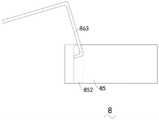
所述卡扣结构包括:卡扣条85,所述卡扣条85呈“Ω”状,所述卡扣条85上设有卡扣凸体851,所述卡扣凸体851与所述卡扣通孔832相配合;拉簧86,所述拉簧86的左右两端分别与所述卡扣条85的左右两端相连接,用于将所述卡扣条85固定在所述第一卡扣槽831上;以及拉绳87,所述拉绳87与所述拉簧86的右端相连接,用于将所述拉簧86的右端拉离所述卡扣条85。所述卡扣条85的两端设有拉簧孔852。The buckle structure includes: a
所述拉簧86包括:左卡钩861,所述左卡钩861穿过所述卡扣条85左端的拉簧孔852,且不能从所述拉簧孔852脱离;左拉簧862,所述左拉簧862与所述左卡钩861连接;右卡钩863,所述右卡钩863穿过所述卡扣条85右端的拉簧孔852,且不能垂直状态的从所述拉簧孔852脱离;右拉簧864,所述右拉簧864与所述右卡钩863连接,所述拉绳87连接在所述右拉簧864处;以及连接条865,所述连接条865的两端分别与所述左拉簧862和所述右拉簧864连接。所述左卡钩861为“”型。所述右卡钩863为“コ”型。所述右卡钩863底部宽度大于所述卡扣条85右端的拉簧孔852的直径。The
需要说明的是,因为所述吸附剂罐8是随身使用,其体积较小,因此活动空间也较小,不方便直接用手将右卡钩863倾斜,且经实验,直接用手去拉右卡钩863时,即使用非常大的力也没办法将其拉出,因此本实施例通过设置拉绳87来拉动右卡钩863,向下按压连接条865,使右卡钩863倾斜,此时再向上或斜向上拉动拉绳87,此时右卡钩863可以倾斜着进入拉簧孔852内,即可轻松将右卡钩863从拉簧孔852脱离。It should be noted that, because the
在一些实施例中,所述氧气罐2连接有气压表,用于监测罐内气体压力。In some embodiments, the
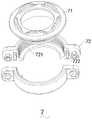
在一些实施例中,所述循环呼吸装置还包括快拆连接件7,所述吸附剂罐8与所述第一肺袋6和所述第二肺袋通过所述快拆连接件7连接。In some embodiments, the rebreathing apparatus further includes a quick-
在一些实施例中,所述呼吸管道11与所述第一肺袋6和所述第二肺袋通过所述快拆连接件7连接,所述自动加气阀5与所述第一肺袋6通过也通过所述快拆连接件7连接。In some embodiments, the
具体的,所述快拆连接件7包括:设有外螺纹的安装圈71,所述安装圈71顶部设有若干第一定位凸体;以及设有内螺纹的固定圈72,所述固定圈72与所述安装圈71螺纹连接,所述固定圈72底部设有第三环形凸体721。所述固定圈72包括设有定位凹槽的右半圈和设有第二定位凸体722的左半圈,所述第二定位凸体722与所述定位凹槽相配合,所述右半圈和所述左半圈通过螺栓固定连接。所述左半圈的两端分别设有第一左耳和第一右耳。所述右半圈的两端分别设有第二左耳和第二右耳,所述第二左耳与所述第一左耳相配合,所述第二右耳与所述第一右耳相配合。所述第一左耳和所述第一右耳上分别设有第一通孔,所述第二左耳和所述第二右耳上分别设有第二通孔,所述第一通孔与所述第二通孔相配合,用于螺栓穿过。Specifically, the quick-
综上所述,本发明包括设有呼吸管道的箱体,所述呼吸管道为单向管道;能够将呼出气体循环利用的循环呼吸装置,所述循环呼吸装置固定在所述箱体内,所述循环呼吸装置包括与所述呼吸管道一端相连的第一肺袋,与所述呼吸管道另一端相连的第二肺袋,及分别与所述第一肺袋和所述第二肺袋相连接的吸附剂罐,所述吸附剂罐用于吸附呼出气体中的二氧化碳;以及能够提供纯氧的纯氧装置,所述纯氧装置固定在所述箱体外侧,所述纯氧装置包括装设有氧气的氧气罐,及与所述氧气罐相连的自动加气阀,所述自动加气阀与所述第一肺袋相连。采用上述设计,使得本发明能够循环利用氧气,能够在下潜不超过6m的深度时使用且能够保持长时间潜水。To sum up, the present invention includes a box body provided with a breathing pipe, and the breathing pipe is a one-way pipe; a circulatory breathing device that can recycle the exhaled gas, the circulatory breathing device is fixed in the box body, and the The circulatory breathing apparatus includes a first lung bag connected to one end of the breathing tube, a second lung bag connected to the other end of the breathing tube, and a lung bag connected to the first lung bag and the second lung bag respectively. an adsorbent tank, the adsorbent tank is used for adsorbing carbon dioxide in exhaled gas; and a pure oxygen device capable of providing pure oxygen, the pure oxygen device is fixed on the outside of the box body, and the pure oxygen device includes a An oxygen tank for oxygen, and an automatic gas filling valve connected with the oxygen tank, the automatic gas filling valve is connected with the first lung bag. By adopting the above design, the present invention can recycle oxygen, can be used when diving to a depth of not more than 6m, and can maintain long-term diving.
以上所述实施例仅表达了本发明的一种或者多种实施方式,其描述较为具体和详细,但并不能因此而理解为对发明专利范围的限制。应当指出的是,对于本领域的普通技术人员来说,在不脱离本发明构思的前提下,还可以做出若干变形和改进,这些都属于本发明的保护范围。因此,本发明专利的保护范围应以所附权利要求为准。The above-mentioned embodiments only represent one or more embodiments of the present invention, and the descriptions thereof are specific and detailed, but should not be construed as a limitation on the scope of the invention patent. It should be pointed out that for those of ordinary skill in the art, without departing from the concept of the present invention, several modifications and improvements can also be made, which all belong to the protection scope of the present invention. Therefore, the protection scope of the patent of the present invention should be subject to the appended claims.
Claims (6)
Applications Claiming Priority (2)
| Application Number | Priority Date | Filing Date | Title |
|---|---|---|---|
| CN2021105801716 | 2021-05-26 | ||
| CN202110580171.6ACN113120195A (en) | 2021-05-26 | 2021-05-26 | Pure oxygen type closed circulation respiratory |
Publications (1)
| Publication Number | Publication Date |
|---|---|
| CN114889783Atrue CN114889783A (en) | 2022-08-12 |
Family
ID=76782573
Family Applications (2)
| Application Number | Title | Priority Date | Filing Date |
|---|---|---|---|
| CN202110580171.6AWithdrawnCN113120195A (en) | 2021-05-26 | 2021-05-26 | Pure oxygen type closed circulation respiratory |
| CN202210583166.5APendingCN114889783A (en) | 2021-05-26 | 2022-05-26 | Pure oxygen type closed circulation respiratory |
Family Applications Before (1)
| Application Number | Title | Priority Date | Filing Date |
|---|---|---|---|
| CN202110580171.6AWithdrawnCN113120195A (en) | 2021-05-26 | 2021-05-26 | Pure oxygen type closed circulation respiratory |
Country Status (1)
| Country | Link |
|---|---|
| CN (2) | CN113120195A (en) |
Cited By (1)
| Publication number | Priority date | Publication date | Assignee | Title |
|---|---|---|---|---|
| CN116039879A (en)* | 2023-02-03 | 2023-05-02 | 中国人民解放军海军特色医学中心 | Circulating type scuba and method for judging use condition of carbon dioxide absorbent |
Families Citing this family (1)
| Publication number | Priority date | Publication date | Assignee | Title |
|---|---|---|---|---|
| CN118358727A (en)* | 2024-04-30 | 2024-07-19 | 广东省兆方科技有限公司 | Air circuit system of a single-person diving breathing apparatus |
Citations (5)
| Publication number | Priority date | Publication date | Assignee | Title |
|---|---|---|---|---|
| CN102210911A (en)* | 2010-04-08 | 2011-10-12 | 德拉格安全股份两合公司 | Respiratory cycle device |
| CN203581360U (en)* | 2013-09-26 | 2014-05-07 | 宜兴市晟裕环保科技有限公司 | Closed-type diving breathing device |
| CN109229308A (en)* | 2018-09-30 | 2019-01-18 | 天津市鹏天工贸有限公司 | From taking the double air supply system enclosed circulation aqualungs not depressurized |
| CN111184953A (en)* | 2020-01-22 | 2020-05-22 | 北京机械设备研究所 | Single-channel gas circuit device of self-rescue respirator and oxygen supply method thereof |
| CN112469626A (en)* | 2018-12-14 | 2021-03-09 | 水呼吸器有限公司 | Personal self-contained breathing apparatus with closed cycle for underwater submersion |
- 2021
- 2021-05-26CNCN202110580171.6Apatent/CN113120195A/ennot_activeWithdrawn
- 2022
- 2022-05-26CNCN202210583166.5Apatent/CN114889783A/enactivePending
Patent Citations (5)
| Publication number | Priority date | Publication date | Assignee | Title |
|---|---|---|---|---|
| CN102210911A (en)* | 2010-04-08 | 2011-10-12 | 德拉格安全股份两合公司 | Respiratory cycle device |
| CN203581360U (en)* | 2013-09-26 | 2014-05-07 | 宜兴市晟裕环保科技有限公司 | Closed-type diving breathing device |
| CN109229308A (en)* | 2018-09-30 | 2019-01-18 | 天津市鹏天工贸有限公司 | From taking the double air supply system enclosed circulation aqualungs not depressurized |
| CN112469626A (en)* | 2018-12-14 | 2021-03-09 | 水呼吸器有限公司 | Personal self-contained breathing apparatus with closed cycle for underwater submersion |
| CN111184953A (en)* | 2020-01-22 | 2020-05-22 | 北京机械设备研究所 | Single-channel gas circuit device of self-rescue respirator and oxygen supply method thereof |
Cited By (1)
| Publication number | Priority date | Publication date | Assignee | Title |
|---|---|---|---|---|
| CN116039879A (en)* | 2023-02-03 | 2023-05-02 | 中国人民解放军海军特色医学中心 | Circulating type scuba and method for judging use condition of carbon dioxide absorbent |
Also Published As
| Publication number | Publication date |
|---|---|
| CN113120195A (en) | 2021-07-16 |
Similar Documents
| Publication | Publication Date | Title |
|---|---|---|
| CN114889783A (en) | Pure oxygen type closed circulation respiratory | |
| KR101743271B1 (en) | Emergency Escape Respirator | |
| CN202777378U (en) | Respiratory valve | |
| CN116674722B (en) | Rebreather, breathing system and operating method thereof | |
| CN220465758U (en) | Multifunctional circulating breathing equipment | |
| CN205814901U (en) | A kind of Self-saving breather of chemical oxygen | |
| CN217575559U (en) | Light underwater circulation respirator | |
| CN206391334U (en) | A kind of safe oxygen head box for hyperbaric oxygen chamber | |
| CN115027646B (en) | Light underwater circulation respirator | |
| CN109529214B (en) | A convenient breathing mask with monitoring function | |
| TWI764832B (en) | Structural Improvement of Breathing Valve for Diving Circulation System | |
| CN114750904A (en) | Closed circulation respiratory system of long worker's hour | |
| CN111184953A (en) | Single-channel gas circuit device of self-rescue respirator and oxygen supply method thereof | |
| CN117382850A (en) | Life-saving respirator and underwater escape method | |
| CN112933448B (en) | A double-bag separately controlled positive pressure oxygen breathing circulation gas storage device | |
| CN206679231U (en) | A kind of underwater breathing apparatus | |
| CN222641113U (en) | Fire-fighting escape self-rescue breathing mask with compressed oxygen bottle isolated type air supply | |
| CN210144941U (en) | Oxygen intake and exhaust control device for oxygen chamber | |
| CN210681099U (en) | Portable diving breathing apparatus | |
| TWM622552U (en) | Breather valve structural improvement for diving circulation system | |
| CN110101987B (en) | Foldable gas mask | |
| GB2340760A (en) | A mouthpiece valve for closed-loop self-contained breathing apparatus | |
| CN222854471U (en) | Chemical oxygen self-rescue respirator connector | |
| CN215275481U (en) | Novel breathing device | |
| CN220842923U (en) | Time-prolonged circulating type scuba |
Legal Events
| Date | Code | Title | Description |
|---|---|---|---|
| PB01 | Publication | ||
| PB01 | Publication | ||
| SE01 | Entry into force of request for substantive examination | ||
| SE01 | Entry into force of request for substantive examination | ||
| RJ01 | Rejection of invention patent application after publication | Application publication date:20220812 | |
| RJ01 | Rejection of invention patent application after publication |