CN114889327B - Electrostatic inkjet printer nozzle and preparation method thereof - Google Patents
Electrostatic inkjet printer nozzle and preparation method thereofDownload PDFInfo
- Publication number
- CN114889327B CN114889327BCN202210423716.7ACN202210423716ACN114889327BCN 114889327 BCN114889327 BCN 114889327BCN 202210423716 ACN202210423716 ACN 202210423716ACN 114889327 BCN114889327 BCN 114889327B
- Authority
- CN
- China
- Prior art keywords
- flow
- silicon substrate
- liquid
- limiting
- nozzle
- Prior art date
- Legal status (The legal status is an assumption and is not a legal conclusion. Google has not performed a legal analysis and makes no representation as to the accuracy of the status listed.)
- Active
Links
- 238000002360preparation methodMethods0.000titleclaimsdescription12
- 239000007788liquidSubstances0.000claimsabstractdescription107
- 239000000758substrateSubstances0.000claimsabstractdescription102
- XUIMIQQOPSSXEZ-UHFFFAOYSA-NSiliconChemical compound[Si]XUIMIQQOPSSXEZ-UHFFFAOYSA-N0.000claimsabstractdescription80
- 229910052710siliconInorganic materials0.000claimsabstractdescription80
- 239000010703siliconSubstances0.000claimsabstractdescription80
- 238000003860storageMethods0.000claimsabstractdescription26
- 238000005507sprayingMethods0.000claimsabstractdescription14
- 238000000034methodMethods0.000claimsdescription32
- 239000011521glassSubstances0.000claimsdescription28
- 238000005520cutting processMethods0.000claimsdescription17
- VYPSYNLAJGMNEJ-UHFFFAOYSA-NSilicium dioxideChemical compoundO=[Si]=OVYPSYNLAJGMNEJ-UHFFFAOYSA-N0.000claimsdescription16
- 239000007921spraySubstances0.000claimsdescription15
- 235000012239silicon dioxideNutrition0.000claimsdescription8
- 239000000377silicon dioxideSubstances0.000claimsdescription8
- 230000005684electric fieldEffects0.000claimsdescription2
- 238000005530etchingMethods0.000claims1
- 230000009286beneficial effectEffects0.000abstractdescription2
- 238000000206photolithographyMethods0.000description15
- 238000005516engineering processMethods0.000description9
- 239000012528membraneSubstances0.000description8
- 238000001020plasma etchingMethods0.000description6
- 239000002184metalSubstances0.000description5
- 238000004544sputter depositionMethods0.000description5
- KRHYYFGTRYWZRS-UHFFFAOYSA-NFluoraneChemical compoundFKRHYYFGTRYWZRS-UHFFFAOYSA-N0.000description4
- 230000000694effectsEffects0.000description4
- 238000004519manufacturing processMethods0.000description4
- 238000000623plasma-assisted chemical vapour depositionMethods0.000description4
- 238000007639printingMethods0.000description3
- 229910052796boronInorganic materials0.000description2
- 238000000151depositionMethods0.000description2
- 238000010586diagramMethods0.000description2
- 239000003292glueSubstances0.000description2
- 238000012986modificationMethods0.000description2
- 230000004048modificationEffects0.000description2
- ZOXJGFHDIHLPTG-UHFFFAOYSA-NBoronChemical compound[B]ZOXJGFHDIHLPTG-UHFFFAOYSA-N0.000description1
- 238000005452bendingMethods0.000description1
- -1boron ionsChemical class0.000description1
- 238000004140cleaningMethods0.000description1
- 230000003247decreasing effectEffects0.000description1
- 238000000708deep reactive-ion etchingMethods0.000description1
- 238000009792diffusion processMethods0.000description1
- 238000001125extrusionMethods0.000description1
- 239000013589supplementSubstances0.000description1
Images


Classifications
- B—PERFORMING OPERATIONS; TRANSPORTING
- B41—PRINTING; LINING MACHINES; TYPEWRITERS; STAMPS
- B41J—TYPEWRITERS; SELECTIVE PRINTING MECHANISMS, i.e. MECHANISMS PRINTING OTHERWISE THAN FROM A FORME; CORRECTION OF TYPOGRAPHICAL ERRORS
- B41J2/00—Typewriters or selective printing mechanisms characterised by the printing or marking process for which they are designed
- B41J2/005—Typewriters or selective printing mechanisms characterised by the printing or marking process for which they are designed characterised by bringing liquid or particles selectively into contact with a printing material
- B41J2/01—Ink jet
- B41J2/135—Nozzles
- B41J2/14—Structure thereof only for on-demand ink jet heads
- B41J2/14314—Structure of ink jet print heads with electrostatically actuated membrane
- B—PERFORMING OPERATIONS; TRANSPORTING
- B41—PRINTING; LINING MACHINES; TYPEWRITERS; STAMPS
- B41J—TYPEWRITERS; SELECTIVE PRINTING MECHANISMS, i.e. MECHANISMS PRINTING OTHERWISE THAN FROM A FORME; CORRECTION OF TYPOGRAPHICAL ERRORS
- B41J2/00—Typewriters or selective printing mechanisms characterised by the printing or marking process for which they are designed
- B41J2/005—Typewriters or selective printing mechanisms characterised by the printing or marking process for which they are designed characterised by bringing liquid or particles selectively into contact with a printing material
- B41J2/01—Ink jet
- B41J2/135—Nozzles
- B41J2/16—Production of nozzles
- B41J2/1621—Manufacturing processes
- B41J2/1626—Manufacturing processes etching
- B—PERFORMING OPERATIONS; TRANSPORTING
- B41—PRINTING; LINING MACHINES; TYPEWRITERS; STAMPS
- B41J—TYPEWRITERS; SELECTIVE PRINTING MECHANISMS, i.e. MECHANISMS PRINTING OTHERWISE THAN FROM A FORME; CORRECTION OF TYPOGRAPHICAL ERRORS
- B41J2/00—Typewriters or selective printing mechanisms characterised by the printing or marking process for which they are designed
- B41J2/005—Typewriters or selective printing mechanisms characterised by the printing or marking process for which they are designed characterised by bringing liquid or particles selectively into contact with a printing material
- B41J2/01—Ink jet
- B41J2/135—Nozzles
- B41J2/16—Production of nozzles
- B41J2/1621—Manufacturing processes
- B41J2/1631—Manufacturing processes photolithography
- B—PERFORMING OPERATIONS; TRANSPORTING
- B41—PRINTING; LINING MACHINES; TYPEWRITERS; STAMPS
- B41J—TYPEWRITERS; SELECTIVE PRINTING MECHANISMS, i.e. MECHANISMS PRINTING OTHERWISE THAN FROM A FORME; CORRECTION OF TYPOGRAPHICAL ERRORS
- B41J2/00—Typewriters or selective printing mechanisms characterised by the printing or marking process for which they are designed
- B41J2/005—Typewriters or selective printing mechanisms characterised by the printing or marking process for which they are designed characterised by bringing liquid or particles selectively into contact with a printing material
- B41J2/01—Ink jet
- B41J2/135—Nozzles
- B41J2/16—Production of nozzles
- B41J2/1621—Manufacturing processes
- B41J2/1632—Manufacturing processes machining
- B—PERFORMING OPERATIONS; TRANSPORTING
- B41—PRINTING; LINING MACHINES; TYPEWRITERS; STAMPS
- B41J—TYPEWRITERS; SELECTIVE PRINTING MECHANISMS, i.e. MECHANISMS PRINTING OTHERWISE THAN FROM A FORME; CORRECTION OF TYPOGRAPHICAL ERRORS
- B41J2/00—Typewriters or selective printing mechanisms characterised by the printing or marking process for which they are designed
- B41J2/005—Typewriters or selective printing mechanisms characterised by the printing or marking process for which they are designed characterised by bringing liquid or particles selectively into contact with a printing material
- B41J2/01—Ink jet
- B41J2/135—Nozzles
- B41J2/16—Production of nozzles
- B41J2/1621—Manufacturing processes
- B41J2/164—Manufacturing processes thin film formation
Landscapes
- Engineering & Computer Science (AREA)
- Manufacturing & Machinery (AREA)
- Particle Formation And Scattering Control In Inkjet Printers (AREA)
Abstract
Translated fromChinese
Description
Translated fromChinese技术领域technical field
本发明属于微机电系统制造技术领域,尤其涉及一种静电式喷墨打印机喷头及其制备方法。The invention belongs to the technical field of micro-electromechanical system manufacturing, and in particular relates to an electrostatic ink-jet printer nozzle and a preparation method thereof.
背景技术Background technique
微滴喷射打印技术是一种通过一定的挤压方式产生墨水腔室与外界之间的压力差,导致喷嘴内部压力大于外界压力,进而将墨水推出喷嘴产生微小墨滴的一种打印技术。Droplet jet printing technology is a printing technology that generates a pressure difference between the ink chamber and the outside world through a certain extrusion method, causing the internal pressure of the nozzle to be greater than the external pressure, and then pushing the ink out of the nozzle to produce tiny ink droplets.
静电式喷墨打印头中,墨水能够通过主墨道直接流向各个压力腔之中,使得主墨道与各个压力腔之间的压力差较小,使墨水从主墨道进入腔室的驱动力就会较小,从而导致腔室内的墨水容易出现回流和串扰的情况。In the electrostatic inkjet print head, ink can flow directly into each pressure chamber through the main ink channel, so that the pressure difference between the main ink channel and each pressure chamber is small, and the driving force for ink to enter the chamber from the main ink channel will be smaller, causing the ink in the chamber to be prone to backflow and crosstalk.
针对以上技术问题,故需要进行改进。For above technical problem, so need to improve.
发明内容Contents of the invention
本发明针对现有技术存在的问题,提出了一种静电式喷墨打印机喷头以及其制备方法。Aiming at the problems existing in the prior art, the invention proposes an electrostatic inkjet printer nozzle and a preparation method thereof.
为实现以上目的,本发明采用以下技术方案:To achieve the above object, the present invention adopts the following technical solutions:
一种静电式喷墨打印机喷头,包括第一硅基片和设置在第一硅基片上方的第二硅基片;所述第二硅基片朝向第一硅基片一侧具有储液池;所述第一硅基片上具有连通储液池使液体进入储液池的进液通道和与进液通道间隔设置使储液池内液体流出的喷嘴;所述储液池内还设有将储液池分为进液区与喷液区的限流部;所述限流部位于进液通道与喷嘴之间;所述限流部上具有连通进液区与喷液区的限流通道;所述限流通道上设有限流柱;所述限流柱向限流通道内侧凸起,使限流通道的进液面积大于出液面积。A nozzle of an electrostatic inkjet printer, comprising a first silicon substrate and a second silicon substrate arranged above the first silicon substrate; the second silicon substrate has a liquid reservoir facing the side of the first silicon substrate ; The first silicon substrate has a liquid inlet channel communicating with the liquid storage tank to allow the liquid to enter the liquid storage tank and a nozzle that is spaced from the liquid inlet channel to allow the liquid in the liquid storage tank to flow out; the liquid storage tank is also provided with a liquid storage tank. The pool is divided into a flow limiting part of the liquid inlet area and a liquid spraying area; the flow limiting part is located between the liquid inlet channel and the nozzle; the flow limiting part has a flow limiting channel connecting the liquid inlet area and the liquid spraying area; A flow-limiting column is arranged on the flow-limiting channel; the flow-limiting column protrudes toward the inner side of the flow-limiting channel, so that the liquid inlet area of the flow-limiting channel is larger than the liquid outlet area.
作为优选方案,限流柱阵列式分布在限流通道两侧,所述限流柱为锯齿形,且锯齿斜面朝向进液区;所述限流通道两侧的限流柱交错排列。As a preferred solution, the flow-limiting columns are distributed in an array on both sides of the flow-limiting channel, the flow-limiting columns are zigzag, and the slope of the sawtooth faces the liquid inlet area; the flow-limiting columns on both sides of the flow-limiting channel are arranged in a staggered manner.
作为优选方案,限流柱阵列式分布在限流通道两侧,所述限流柱为圆弧形;所述限流通道两侧的限流柱交错排列,所述限流柱的圆弧内侧朝向喷液区。As a preferred solution, the current limiting columns are distributed in an array on both sides of the current limiting channel, and the current limiting columns are arc-shaped; the current limiting columns on both sides of the current limiting channel are arranged in a staggered manner, and the inner sides of the arc toward the spray area.
作为优选方案,限流部具有多个限流通道。As a preferred solution, the restrictor has a plurality of restrictor channels.
作为优选方案,喷液区内分隔成若干个腔室;所述腔室与限流通道一一对应。As a preferred solution, the spray area is divided into several chambers; the chambers correspond to the flow-limiting channels one by one.
作为优选方案,所述储液池内还设置有喷墨组件,喷墨组件包括设置在进液区内的振动膜片和设置在振动膜片上方使振动膜片振动的固定电极。As a preferred solution, an inkjet assembly is also arranged in the liquid storage pool, and the inkjet assembly includes a vibrating membrane arranged in the liquid inlet area and a fixed electrode arranged above the vibrating membrane to vibrate the vibrating membrane.
作为优选方案,第二硅基片上表面与下表面均设置有二氧化硅绝缘层。As a preferred solution, both the upper surface and the lower surface of the second silicon substrate are provided with a silicon dioxide insulating layer.
本发明还提供如上方案所述的一种静电式喷墨打印机喷头的制备方法,包括步骤:The present invention also provides a method for preparing a spray head of an electrostatic inkjet printer as described in the above scheme, comprising the steps of:
S1、第一硅基片制备;选取硅基片,在第一硅基片下表面刻透出进液通道和喷嘴;S1. Preparation of the first silicon substrate; select the silicon substrate, and engrave the liquid inlet channel and the nozzle on the lower surface of the first silicon substrate;
S2、第二硅基片制备;选取硅基片,在第二硅基片下表面刻蚀出储液池凹槽并在储液池内刻蚀出限流部;S2. Preparation of the second silicon substrate: select the silicon substrate, etch the groove of the liquid storage tank on the lower surface of the second silicon substrate and etch the flow limiting part in the liquid storage tank;
S3、玻璃基片制备;选取玻璃基片,在玻璃基片下表面刻蚀出固定电极凹槽;S3, glass substrate preparation; select the glass substrate, etch the fixed electrode groove on the lower surface of the glass substrate;
S4、安装;采用硅-硅键合处理将第一硅基片与第二硅基片键合安装;采用硅-玻璃键合处理将第二硅基片与玻璃基片键合安装。S4. Installing: bonding and installing the first silicon substrate and the second silicon substrate by silicon-silicon bonding; bonding and installing the second silicon substrate and the glass substrate by silicon-glass bonding.
作为优选方案,步骤S2中,在第二硅基片刻蚀出振动膜片凹槽宽度约为200-500μm,厚度约为5-50μm;所述步骤S3中,在玻璃基片刻蚀出的固定电极凹槽长度为3000-6000μm,宽度为200-500μm,深度约50-100μm。As a preferred solution, in step S2, the vibrating diaphragm groove width is about 200-500 μm and the thickness is about 5-50 μm is etched on the second silicon substrate; in the step S3, the fixed electrode etched on the glass substrate The length of the groove is 3000-6000 μm, the width is 200-500 μm, and the depth is about 50-100 μm.
本发明与现有技术相比,有益效果是:通过在限流通道内设置限流柱,使通过限流通道的液体的流速加快,根据伯努利原理加大进液区与喷液区的压力差进而使液体在通过限流通道后,在压力差的作用下,不会发生回流或者串扰的情况,进而提高了打印机的打印质量,降低了墨水的消耗。Compared with the prior art, the present invention has the beneficial effects that: by setting the flow-limiting column in the flow-limiting channel, the flow velocity of the liquid passing through the flow-limiting channel is accelerated, and the pressure of the liquid inlet area and the liquid spray area is increased according to Bernoulli's principle The difference further prevents the liquid from backflow or crosstalk under the action of the pressure difference after passing through the flow-limiting channel, thereby improving the printing quality of the printer and reducing ink consumption.
附图说明Description of drawings
图1为本发明实施例的静电式喷墨打印机喷头的平面结构示意图;Fig. 1 is the schematic plan view of the nozzle of the electrostatic inkjet printer embodiment of the present invention;
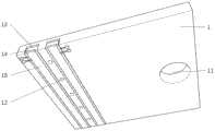
图2为本发明实施例的静电式喷墨打印机喷头的整体结构示意图;2 is a schematic diagram of the overall structure of the spray head of an electrostatic inkjet printer according to an embodiment of the present invention;
图3为本发明实施例一的静电式喷墨打印机喷头的第一硅基片部分结构示意图;3 is a schematic structural view of the first silicon substrate part of the nozzle of the electrostatic inkjet printer according to
图4为本发明实施例一的静电式喷墨打印机喷头的第二硅基片部分结构示意图;4 is a schematic structural view of the second silicon substrate part of the nozzle of the electrostatic inkjet printer according to
图5为本发明实施例一的静电式喷墨打印机喷头的玻璃基片部分结构示意图;5 is a schematic structural view of the glass substrate part of the spray head of the electrostatic inkjet printer according to
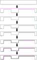
图6为本发明实施例一的静电式喷墨打印机喷头的第一硅基片制作工艺流程图;6 is a flow chart of the first silicon substrate manufacturing process of the nozzle of the electrostatic inkjet printer according to
图7为本发明实施例一的静电式喷墨打印机喷头的第二硅基片制作工艺流程图;Fig. 7 is the process flow chart of the second silicon substrate manufacturing process of the nozzle of the electrostatic inkjet printer according to the first embodiment of the present invention;
图8为本发明实施例一的静电式喷墨打印机喷头的玻璃基片制作工艺流程图;Fig. 8 is the flow chart of the glass substrate manufacturing process of the nozzle of the electrostatic inkjet printer according to
图9为本发明实施例一的静电式喷墨打印机喷头的最终键合示意图;9 is a schematic diagram of the final bonding of the nozzle of the electrostatic inkjet printer according to
其中:1.第一硅基片;11.进液通道;12.喷嘴;13.上电极层;14.PZT压电层;15.下电极层;2.第二硅基片;21.储液池;22.限流部;23.振动膜片;24.振动膜片电极接口;25.振动膜片电极;26.二氧化硅绝缘层;27.二氧化硅绝缘层;3.玻璃基片;31.固定电极;32.接电口;200.进液区;201.喷液区;202.限流通道;203.限流柱;40.喷墨组件。Among them: 1. The first silicon substrate; 11. The liquid inlet channel; 12. The nozzle; 13. The upper electrode layer; 14. The PZT piezoelectric layer; 15. The lower electrode layer; 2. The second silicon substrate; 21. The reservoir Liquid pool; 22. Current limiting part; 23. Vibrating diaphragm; 24. Vibrating diaphragm electrode interface; 25. Vibrating diaphragm electrode; 26. Silicon dioxide insulating layer; 27. Silicon dioxide insulating layer; 3.
具体实施方式Detailed ways
以下通过特定的具体实例说明本发明的实施方式,本领域技术人员可由本说明书所揭露的内容轻易地了解本发明的其他优点与功效。本发明还可以通过另外不同的具体实施方式加以实施或应用,本说明书中的各项细节也可以基于不同观点与应用,在没有背离本发明的精神下进行各种修饰或改变。Embodiments of the present invention are described below through specific examples, and those skilled in the art can easily understand other advantages and effects of the present invention from the content disclosed in this specification. The present invention can also be implemented or applied through other different specific implementation modes, and various modifications or changes can be made to the details in this specification based on different viewpoints and applications without departing from the spirit of the present invention.
实施例一:Embodiment one:
本实施例的静电式喷墨打印机喷头,如图1-5所示,包括第一硅基片1、设置在第一硅基片1上方的第二硅基片2和设置在第二硅基片2上方的玻璃基片3。The electrostatic inkjet printer nozzle of the present embodiment, as shown in Figure 1-5, comprises the
第一硅基片1具有进液通道11和喷嘴12,若干喷嘴12能够组成喷液通路,且喷液通路阵列位于第一硅基片1与第二硅基片2的键合面之间。The
第二硅基片2的下表面还具有连通进液通道11的储液池21和设置在储液池21内的限制墨水回流的限流部22。The lower surface of the
如图4所示,限流部22将储液池21分隔成进液区200与喷液区201,限流部22上还具有连通进液区200与喷液区201的限流通道202,液体通过进液通道11进入储液池21进液区,在通过限流部22内的限流通道202流向喷液区201,最后液体通过喷嘴12从喷液区201离开。As shown in FIG. 4 , the
限流通道202内设有增大液体通过限流通道202流速的限流柱203,限流柱203阵列式分布在限流通道202两侧,限流柱203为锯齿形。限流柱203的锯齿斜面朝向进液区200,限流通道202两侧的限制柱203层交错排列。The flow-limiting
通过限流通道202两侧交错排列的限流柱203,使限流通道202形成锯齿状的流路,并使限流通道202的进液口大于出液口,锯齿状不仅能起到阻碍回流的作用还能进一步增大限流通道202内的压力差。The flow-limiting
液体通过限流柱203上的斜面,在流量不变的情况下,增大液体的行程,进而使增加液体通过限流通道202的流速,使进液区200与喷液区201产生压力差,使通过限流通道202进入喷液区201内的液体在压力差的作用下不会发生回来和串扰的情况。The liquid passes through the slope on the flow-limiting
限流部22上设置有多个限流通道202,每个通道内都设置有限流柱203。喷液区分隔成多个腔室,每个腔室与一个限流通道202相对对应,液体能够通过不同的限流通道202从进液区流向不同的腔室。A plurality of flow-limiting
储液池21上方设置喷墨组件40。喷墨组件40包括能够通过受力能发生弯曲产生吸力的振动膜片23和设置在振动膜片23上方为其提供静电力的固定电极31。第二硅基片2上还设置有与振动膜片23适配的振动膜片电极接口24和振动膜片电极25。第二硅基片的上表面还设置有二氧化硅绝缘层27。An
如图3所示,第一硅基片1下方设置有对墨滴切割的切割头,切割头包括设置在第一硅基片1上的上电极层13、设置在上电极层13下方的PZT压电层14和嵌设在PZT压电层下表面的下电极层15,所述PZT压电层14的逆压电效应形变方向垂直于电场方向,PZT压电层14包裹下电极层15两侧。As shown in Figure 3, a cutting head for cutting ink droplets is provided below the
如图5所示,固定电极31四周被玻璃基片3包围,固定电极31导线阵列于玻璃基片3下表面,通过接电口32与外部电路相连。As shown in FIG. 5 , the fixed
如图6至图9所示,本实施例的静电式喷墨打印机喷头的制备方法,包括以下步骤:As shown in Figures 6 to 9, the preparation method of the nozzle of the electrostatic inkjet printer of the present embodiment comprises the following steps:
S1.选取4inch硅基片,采用光刻工艺将进液通道和喷嘴图形转移至第一硅基片1的下表面,并采用深反应离子刻蚀技术,刻透进液通道11和喷嘴区;S1. Select a 4inch silicon substrate, transfer the liquid inlet channel and the nozzle pattern to the lower surface of the
S2.采用光刻工艺将切割头的图形转移到第一硅基片1的下表面,并采用反应离子刻蚀技术,刻蚀出切割头凹槽约10-100μm;S2. Using a photolithography process to transfer the pattern of the cutting head to the lower surface of the
S3.采用PECVD工艺,在第一硅基片1的下表面沉积一层二氧化硅;S3. Depositing a layer of silicon dioxide on the lower surface of the
S4.采用光刻工艺和金属溅射工艺,在切割头凹槽制备切割头的上电极层13;S4. Prepare the
S5.采用光刻工艺和PECVD工艺,将PZT沉积到切割头凹槽内,形成PZT压电层14;S5. Depositing PZT into the groove of the cutting head by using a photolithography process and a PECVD process to form a
S6.采用光刻工艺和金属溅射工艺,在截割头凹槽制备切割头的下电极层15,去胶并清洗硅片;S6. Using a photolithography process and a metal sputtering process, prepare the
S7.选取4inch硅基片,采用光刻工艺,将储液池21图形转移至第二硅基片2的下表面,采用反应离子刻蚀技术,刻蚀出储液池21凹槽,使得振动膜片23宽度约为200-500μm,厚度约为5-50μm;S7. Select a 4inch silicon substrate, use a photolithography process, transfer the pattern of the
S8.采用光刻工艺和浓硼扩散工艺,在储液池21上的硅片薄板掺杂硼离子,制备出硼硅膜的振动膜片23;S8. Using a photolithography process and a concentrated boron diffusion process, the silicon wafer thin plate on the
S9.采用光刻工艺,将限流部22图形转移至第二硅基片2的下表面,采用反应离子刻蚀技术,刻蚀出限流部22凹槽;S9. Using a photolithography process, transfer the pattern of the current limiting
S10.采用光刻工艺,将振动膜片23图形转移至第二硅基片2的下表面,采用反应离子刻蚀技术,刻蚀出振动膜片凹槽;S10. Using a photolithography process, transfer the pattern of the vibrating
S11.采用金属溅射工艺,在振动膜片凹槽制备出振动膜片23;S11. Using a metal sputtering process, the vibrating
S12.采用光刻工艺和金属溅射工艺,在储液池21凹槽和限流部22凹槽下表面,制备出振动膜片电极25;S12. Using a photolithography process and a metal sputtering process, a vibrating
S13.采用光刻工艺和PECVD工艺,在第二硅基片2的下表面,沉积一层二氧化硅绝缘层26;清洗硅片;S13. Deposit a layer of silicon
S14.采用光刻工艺和PECVD工艺,在第二硅基片2的上表面,沉积一层二氧化硅绝缘层27;S14. Deposit a layer of silicon
S15.选取4inch玻璃基片,采用光刻工艺将静电电极凹槽图形转移至玻璃基片3下表面,并采用反应离子刻蚀技术,刻蚀出固定电极31凹槽,固定电极凹槽长度为3000-6000μm,宽度为200-500μm,深度约20-50μm;S15. Select a 4inch glass substrate, use a photolithography process to transfer the groove pattern of the electrostatic electrode to the lower surface of the
S16.采用光刻工艺将接电口32图形转移至玻璃基片3下表面,并采用反应离子刻蚀技术,刻蚀出接电口32;S16. Transfer the pattern of the
S17.采用光刻工艺和金属溅射工艺,在玻璃基片3上制备固定电极31及导线阵列,去胶并清洗玻璃基片3;S17. Using a photolithography process and a metal sputtering process, prepare a fixed
S18.采用氢氟酸漂洗第一硅基片1的上表面和第二硅基片2的下表面,并采用硅-硅键合工艺将第一硅基片1的上表面和第二硅基片2的下表面键合;S18. Use hydrofluoric acid to rinse the upper surface of the
S19.采用氢氟酸漂洗第二硅基片2的上表面和玻璃基片3的下表面,并采用硅-玻璃键合工艺将第二硅基片2的上表面和玻璃基片3的下表面键合;S19. Use hydrofluoric acid to rinse the upper surface of the
S20.清洗并划片,完成制备。S20. Cleaning and dicing to complete the preparation.
在打印机喷头工作时,固定电极31接受到电压,振动膜片23在静电力作用下向上弯曲,吸入墨水;然后固定电极31电压消失,振动膜片23复位,挤压墨水喷出,在墨水挤出后,切割头开始工作,在墨滴速度达到最大时,利用逆压电效应,使切割头形变推挤喷嘴12切割墨滴,避免卫星墨滴的产生;墨滴喷出后,切割头打开,开始下一轮墨滴的喷出。When the printer nozzle is working, the fixed
本实例的静电式喷墨打印机喷头在传统喷墨打印机喷头的基础上,增加了切割头,避免了墨滴在喷射过程中产生长尾柱,可以有效的控制墨滴的体积,提高墨滴喷出速度;同时设计了锯齿状限流部,通过多重限流柱阻止墨水回流,降低了喷嘴之间的串扰,在工艺允许的情况下可以进一步减小喷头尺寸,使喷头的排列更加紧密。The nozzle of the electrostatic inkjet printer in this example is based on the nozzle of the traditional inkjet printer, and a cutting head is added to avoid the long tail column of the ink drop during the spraying process, which can effectively control the volume of the ink drop and improve the ink droplet spraying rate. At the same time, a sawtooth-shaped restrictor is designed to prevent the ink from flowing back through multiple restrictors, reducing the crosstalk between nozzles. If the process allows, the size of the nozzle can be further reduced to make the arrangement of the nozzle more compact.
本实施例阵列式喷液通路中的喷液通路的数量不限于实施例一所示的数量,还可以根据实际应用需求进行增加或减少。The number of liquid spraying channels in the arrayed liquid spraying channels of this embodiment is not limited to the number shown in
实施例二:Embodiment two:
本实施例与实施例一的不同之处在于,限流柱为圆弧形,限流柱圆弧内侧朝向喷液区,其他具体结构与实施例一相同。The difference between this embodiment and the first embodiment lies in that the current limiting column is arc-shaped, and the inner side of the arc of the current limiting column faces the spraying area, and other specific structures are the same as the first embodiment.
本文中所描述的具体实施例仅仅是对本发明精神作举例说明。本发明所属技术领域的技术人员可以对所描述的具体实施例做各种各样的修改或补充或采用类似的方式替代,但并不会偏离本发明的精神或者超越所附权利要求书所定义的范围。The specific embodiments described herein are merely illustrative of the spirit of the invention. Those skilled in the art to which the present invention belongs can make various modifications or supplements to the described specific embodiments or adopt similar methods to replace them, but they will not deviate from the spirit of the present invention or go beyond the definition of the appended claims range.
Claims (10)
Translated fromChinesePriority Applications (1)
| Application Number | Priority Date | Filing Date | Title |
|---|---|---|---|
| CN202210423716.7ACN114889327B (en) | 2022-04-21 | 2022-04-21 | Electrostatic inkjet printer nozzle and preparation method thereof |
Applications Claiming Priority (1)
| Application Number | Priority Date | Filing Date | Title |
|---|---|---|---|
| CN202210423716.7ACN114889327B (en) | 2022-04-21 | 2022-04-21 | Electrostatic inkjet printer nozzle and preparation method thereof |
Publications (2)
| Publication Number | Publication Date |
|---|---|
| CN114889327A CN114889327A (en) | 2022-08-12 |
| CN114889327Btrue CN114889327B (en) | 2023-05-12 |
Family
ID=82717693
Family Applications (1)
| Application Number | Title | Priority Date | Filing Date |
|---|---|---|---|
| CN202210423716.7AActiveCN114889327B (en) | 2022-04-21 | 2022-04-21 | Electrostatic inkjet printer nozzle and preparation method thereof |
Country Status (1)
| Country | Link |
|---|---|
| CN (1) | CN114889327B (en) |
Citations (4)
| Publication number | Priority date | Publication date | Assignee | Title |
|---|---|---|---|---|
| US4068241A (en)* | 1975-12-08 | 1978-01-10 | Hitachi, Ltd. | Ink-jet recording device with alternate small and large drops |
| US6382782B1 (en)* | 2000-12-29 | 2002-05-07 | Eastman Kodak Company | CMOS/MEMS integrated ink jet print head with oxide based lateral flow nozzle architecture and method of forming same |
| EP1219424A2 (en)* | 2000-12-29 | 2002-07-03 | Eastman Kodak Company | Cmos/mems integrated ink jet print head with silicon based lateral flow nozzle architecture and method of forming same |
| CN101308339A (en)* | 2007-05-16 | 2008-11-19 | 株式会社理光 | Toner preparation method and apparatus, and toner prepared thereby |
Family Cites Families (9)
| Publication number | Priority date | Publication date | Assignee | Title |
|---|---|---|---|---|
| JP2007111957A (en)* | 2005-10-19 | 2007-05-10 | Seiko Epson Corp | Droplet discharge head, manufacturing method thereof, and droplet discharge apparatus |
| JP2009137133A (en)* | 2007-12-05 | 2009-06-25 | Seiko Epson Corp | Method for manufacturing liquid jet head and method for etching crystal substrate |
| KR20110139494A (en)* | 2010-06-23 | 2011-12-29 | 삼성전기주식회사 | Ink flow structure and ink jet head comprising the same |
| CN108909185B (en)* | 2018-06-15 | 2020-07-17 | 大连瑞林数字印刷技术有限公司 | A piezoelectric inkjet print head driven by a thick-film piezoelectric element |
| CN209141700U (en)* | 2018-09-30 | 2019-07-23 | 西安增材制造国家研究院有限公司 | A kind of current limiter in droplet ejection print head |
| CN109130509B (en)* | 2018-09-30 | 2024-01-09 | 西安增材制造国家研究院有限公司 | Restrictor in a droplet ejection printhead |
| CN111038105B (en)* | 2019-12-19 | 2021-09-07 | 西安增材制造国家研究院有限公司 | Piezoelectric type ink-jet printing head |
| CN112265376B (en)* | 2020-10-13 | 2022-06-14 | 武汉科技大学 | Addressable electrofluid ink-jet printing head and printing method |
| CN113059914B (en)* | 2021-03-25 | 2022-07-08 | 苏州印科杰特半导体科技有限公司 | Liquid jet flow passage |
- 2022
- 2022-04-21CNCN202210423716.7Apatent/CN114889327B/enactiveActive
Patent Citations (4)
| Publication number | Priority date | Publication date | Assignee | Title |
|---|---|---|---|---|
| US4068241A (en)* | 1975-12-08 | 1978-01-10 | Hitachi, Ltd. | Ink-jet recording device with alternate small and large drops |
| US6382782B1 (en)* | 2000-12-29 | 2002-05-07 | Eastman Kodak Company | CMOS/MEMS integrated ink jet print head with oxide based lateral flow nozzle architecture and method of forming same |
| EP1219424A2 (en)* | 2000-12-29 | 2002-07-03 | Eastman Kodak Company | Cmos/mems integrated ink jet print head with silicon based lateral flow nozzle architecture and method of forming same |
| CN101308339A (en)* | 2007-05-16 | 2008-11-19 | 株式会社理光 | Toner preparation method and apparatus, and toner prepared thereby |
Also Published As
| Publication number | Publication date |
|---|---|
| CN114889327A (en) | 2022-08-12 |
Similar Documents
| Publication | Publication Date | Title |
|---|---|---|
| CN1144680C (en) | Device for using bubble as a virtual valve in micro-ejector | |
| EP1321294B1 (en) | Piezoelectric ink-jet printhead and method for manufacturing the same | |
| KR100590558B1 (en) | Piezoelectric inkjet printhead and its manufacturing method | |
| WO1994015791A1 (en) | Ink jet head | |
| CN113352758B (en) | High-speed printer ink-jet head based on magnetostriction effect and preparation method thereof | |
| CN114889327B (en) | Electrostatic inkjet printer nozzle and preparation method thereof | |
| CN201220507Y (en) | Liquid injection structure based on piezoelectric cantilever beam | |
| CN114801492B (en) | A dual-drive high-speed ink-jet printer nozzle without satellite ink droplets and its processing method | |
| CN114889325B (en) | High-precision piezoelectric type inkjet printer nozzle and preparation method thereof | |
| CN115091854B (en) | High-precision electrostatic type inkjet printer nozzle and processing method thereof | |
| CN114889326B (en) | High-precision thermal bubble type inkjet printer nozzle and processing method thereof | |
| JP2004167951A (en) | Droplet discharge head, method of manufacturing the same, ink cartridge, and inkjet recording apparatus | |
| JP4061953B2 (en) | Ink jet head and manufacturing method thereof | |
| JP2004306396A (en) | Droplet discharge head and method of manufacturing the same, ink cartridge and ink jet recording apparatus | |
| CN101269363A (en) | Liquid spray head based on piezoelectric cantilever beam | |
| JP2008260236A (en) | Droplet discharge head, droplet discharge apparatus, and discharge control method thereof | |
| JP2008132763A (en) | Nozzle substrate manufacturing method, droplet discharge head manufacturing method, droplet discharge device manufacturing method, nozzle substrate, droplet discharge head, and droplet discharge device | |
| JP2003200578A (en) | Manufacturing method of liquid ejection head | |
| JP4151226B2 (en) | Inkjet head | |
| JPH09300630A (en) | Inkjet head manufacturing method | |
| JP2001010036A (en) | Ink jet head, method of manufacturing the same, and ink jet recording apparatus | |
| KR100641286B1 (en) | Micro Precision Droplet Injection Head and Manufacturing Method Using Piezoelectric Method | |
| JP2009006617A (en) | Electrostatic actuator, liquid droplet discharge head, liquid droplet discharge device, manufacturing method of electrostatic actuator, manufacturing method of liquid droplet discharge head, and manufacturing method of liquid droplet discharge device | |
| JP2000289205A (en) | Ink jet head and method of manufacturing the same | |
| JP2001047621A (en) | Electrostatic inkjet head |
Legal Events
| Date | Code | Title | Description |
|---|---|---|---|
| PB01 | Publication | ||
| PB01 | Publication | ||
| SE01 | Entry into force of request for substantive examination | ||
| SE01 | Entry into force of request for substantive examination | ||
| GR01 | Patent grant | ||
| GR01 | Patent grant |