CN114886556A - Device for blood intraluminal treatment using ultrafast laser - Google Patents
Device for blood intraluminal treatment using ultrafast laserDownload PDFInfo
- Publication number
- CN114886556A CN114886556ACN202210334439.2ACN202210334439ACN114886556ACN 114886556 ACN114886556 ACN 114886556ACN 202210334439 ACN202210334439 ACN 202210334439ACN 114886556 ACN114886556 ACN 114886556A
- Authority
- CN
- China
- Prior art keywords
- ultrafast laser
- fiber
- laser
- ultrafast
- optical fiber
- Prior art date
- Legal status (The legal status is an assumption and is not a legal conclusion. Google has not performed a legal analysis and makes no representation as to the accuracy of the status listed.)
- Pending
Links
Images


Classifications
- A—HUMAN NECESSITIES
- A61—MEDICAL OR VETERINARY SCIENCE; HYGIENE
- A61B—DIAGNOSIS; SURGERY; IDENTIFICATION
- A61B18/00—Surgical instruments, devices or methods for transferring non-mechanical forms of energy to or from the body
- A61B18/18—Surgical instruments, devices or methods for transferring non-mechanical forms of energy to or from the body by applying electromagnetic radiation, e.g. microwaves
- A61B18/20—Surgical instruments, devices or methods for transferring non-mechanical forms of energy to or from the body by applying electromagnetic radiation, e.g. microwaves using laser
- A61B18/22—Surgical instruments, devices or methods for transferring non-mechanical forms of energy to or from the body by applying electromagnetic radiation, e.g. microwaves using laser the beam being directed along or through a flexible conduit, e.g. an optical fibre; Couplings or hand-pieces therefor
- A61B18/24—Surgical instruments, devices or methods for transferring non-mechanical forms of energy to or from the body by applying electromagnetic radiation, e.g. microwaves using laser the beam being directed along or through a flexible conduit, e.g. an optical fibre; Couplings or hand-pieces therefor with a catheter
- A61B18/245—Surgical instruments, devices or methods for transferring non-mechanical forms of energy to or from the body by applying electromagnetic radiation, e.g. microwaves using laser the beam being directed along or through a flexible conduit, e.g. an optical fibre; Couplings or hand-pieces therefor with a catheter for removing obstructions in blood vessels or calculi
- A—HUMAN NECESSITIES
- A61—MEDICAL OR VETERINARY SCIENCE; HYGIENE
- A61B—DIAGNOSIS; SURGERY; IDENTIFICATION
- A61B18/00—Surgical instruments, devices or methods for transferring non-mechanical forms of energy to or from the body
- A61B2018/00315—Surgical instruments, devices or methods for transferring non-mechanical forms of energy to or from the body for treatment of particular body parts
- A61B2018/00345—Vascular system
- A61B2018/00351—Heart
- A—HUMAN NECESSITIES
- A61—MEDICAL OR VETERINARY SCIENCE; HYGIENE
- A61B—DIAGNOSIS; SURGERY; IDENTIFICATION
- A61B18/00—Surgical instruments, devices or methods for transferring non-mechanical forms of energy to or from the body
- A61B2018/00636—Sensing and controlling the application of energy
- A61B2018/00696—Controlled or regulated parameters
- A61B2018/00702—Power or energy
- A—HUMAN NECESSITIES
- A61—MEDICAL OR VETERINARY SCIENCE; HYGIENE
- A61B—DIAGNOSIS; SURGERY; IDENTIFICATION
- A61B18/00—Surgical instruments, devices or methods for transferring non-mechanical forms of energy to or from the body
- A61B2018/00636—Sensing and controlling the application of energy
- A61B2018/00773—Sensed parameters
- A61B2018/00779—Power or energy
- A—HUMAN NECESSITIES
- A61—MEDICAL OR VETERINARY SCIENCE; HYGIENE
- A61B—DIAGNOSIS; SURGERY; IDENTIFICATION
- A61B18/00—Surgical instruments, devices or methods for transferring non-mechanical forms of energy to or from the body
- A61B18/18—Surgical instruments, devices or methods for transferring non-mechanical forms of energy to or from the body by applying electromagnetic radiation, e.g. microwaves
- A61B18/20—Surgical instruments, devices or methods for transferring non-mechanical forms of energy to or from the body by applying electromagnetic radiation, e.g. microwaves using laser
- A61B18/22—Surgical instruments, devices or methods for transferring non-mechanical forms of energy to or from the body by applying electromagnetic radiation, e.g. microwaves using laser the beam being directed along or through a flexible conduit, e.g. an optical fibre; Couplings or hand-pieces therefor
- A61B2018/2205—Characteristics of fibres
Landscapes
- Health & Medical Sciences (AREA)
- Life Sciences & Earth Sciences (AREA)
- Physics & Mathematics (AREA)
- Surgery (AREA)
- Electromagnetism (AREA)
- Heart & Thoracic Surgery (AREA)
- Otolaryngology (AREA)
- Optics & Photonics (AREA)
- Vascular Medicine (AREA)
- Engineering & Computer Science (AREA)
- Biomedical Technology (AREA)
- Nuclear Medicine, Radiotherapy & Molecular Imaging (AREA)
- Medical Informatics (AREA)
- Molecular Biology (AREA)
- Animal Behavior & Ethology (AREA)
- General Health & Medical Sciences (AREA)
- Public Health (AREA)
- Veterinary Medicine (AREA)
- Laser Surgery Devices (AREA)
Abstract
Translated fromChinese
Description
Translated fromChinese技术领域technical field
本发明涉及医疗器械技术领域,尤其是涉及一种利用超快激光供血管腔内治疗的装置。The invention relates to the technical field of medical devices, in particular to a device for intravascular treatment using ultrafast laser.
背景技术Background technique
血栓和动脉粥样硬化斑块是人类心血管疾病的首要病因。血栓主要由人体内纤维蛋白、血小板、白细胞和红细胞等部分组成,可累及冠状动脉与外周动静脉,由血栓引发的脏器组织急性缺血致死率极高。动脉粥样硬化斑块是沿中等动脉和大动脉的壁上形成含有胆固醇、脂肪酸、细胞废物和钙化沉积的硬化斑块,可导致中等动脉和大动脉等血管管腔变窄,是冠心病、中风及外周动脉硬化性疾病的主导原因。因此,防治血栓和动脉粥样硬化斑块是降低人群死亡率、改善生命质量和缓解社会医疗负担的重要问题。Thrombosis and atherosclerotic plaque are the leading causes of cardiovascular disease in humans. Thrombosis is mainly composed of fibrin, platelets, white blood cells and red blood cells in the human body, and can involve coronary arteries and peripheral arteries and veins. Atherosclerotic plaque is a sclerotic plaque containing cholesterol, fatty acids, cellular waste and calcified deposits formed along the walls of medium and large arteries, which can lead to narrowing of the lumen of blood vessels such as medium and large arteries. Leading cause of peripheral arteriosclerotic disease. Therefore, the prevention and treatment of thrombosis and atherosclerotic plaque is an important issue to reduce the mortality rate, improve the quality of life and alleviate the social medical burden.
目前,清除血管腔内血栓和斑块的手段主要包括药物治疗和手术治疗两大类,除少数急性期病症可采取药物治疗外,大部分血栓和斑块仍需借助手术清除,以快速减少血管腔内负荷,改善器官功能。现代微创手术利用微创导管经药物或器械清除血栓和斑块,手术创伤较小,但仍存在一定局限,如药物溶栓导管需长时留置、溶栓药物存在出血风险、机械清除导管对亚急性血栓相对低效或血管壁损伤破裂风险高等,限制了当前微创血栓清除手术的广泛开展。At present, the means of removing thrombus and plaque in the vascular cavity mainly include drug treatment and surgical treatment. Except for a few acute diseases that can be treated with drugs, most thrombus and plaque still need to be removed by surgery to quickly reduce blood vessels. Intraluminal load, improve organ function. Modern minimally invasive surgery uses minimally invasive catheters to remove thrombus and plaques with drugs or instruments. The surgical trauma is small, but there are still certain limitations, such as the need for long-term indwelling of drug thrombolytic catheters, the risk of bleeding with thrombolytic drugs, and mechanical removal of catheters. The relatively low efficacy of subacute thrombus or the high risk of rupture of the vessel wall limits the widespread implementation of minimally invasive thrombectomy.
发明内容SUMMARY OF THE INVENTION
本发明旨在至少解决现有技术中存在的技术问题之一。为此,本发明的一个目的在于提出一种利用超快激光供血管腔内治疗的装置,可以安全高效清除血栓和斑块以实现良好的血管腔内消蚀减容效果。The present invention aims to solve at least one of the technical problems existing in the prior art. To this end, an object of the present invention is to provide a device for intravascular treatment using ultrafast laser, which can safely and efficiently remove thrombus and plaque to achieve a good effect of intraluminal ablation and volume reduction.
根据本发明实施例的利用超快激光供血管腔内治疗的装置,包括超快激光器、光纤导管、光纤耦合模块和手术辅助结构;其中,所述超快激光器用于产生并输出超快激光脉冲;所述光纤耦合模块设置在所述光纤导管的输入端处,用于耦合所述超快激光器输出的超快激光脉冲并将超快激光脉冲传输给所述光纤导管的传导光纤束,所述传导光纤束用于接收所述光纤耦合模块输给的超快激光脉冲并传输至所述光纤导管的输出端,由所述光纤导管的所述输出端向前输出超快激光脉冲以对血管腔内病变进行辐射消蚀;所述手术辅助结构用于设置在所述光纤导管的空腔结构中,将所述光纤导管引导至血管腔内病变处,以及用于向血管腔内病变处输送冷却液体、造影剂或/和药物。An apparatus for intravascular treatment using an ultrafast laser according to an embodiment of the present invention includes an ultrafast laser, an optical fiber catheter, an optical fiber coupling module and a surgical auxiliary structure; wherein the ultrafast laser is used to generate and output ultrafast laser pulses The optical fiber coupling module is arranged at the input end of the optical fiber conduit, and is used for coupling the ultrafast laser pulse output by the ultrafast laser and transmitting the ultrafast laser pulse to the conducting fiber bundle of the optical fiber conduit. The conducting fiber bundle is used for receiving the ultrafast laser pulses input from the fiber coupling module and transmitting to the output end of the fiber optic catheter, and the ultrafast laser pulses are outputted forward from the output end of the fiber optic catheter to align the blood vessel cavity. Radiation ablation is performed on the intravascular lesions; the surgical auxiliary structure is used to be arranged in the cavity structure of the optical fiber catheter, to guide the optical fiber catheter to the intravascular lesion, and to deliver cooling to the intravascular lesion Fluids, contrast media or/and medicines.
根据本发明实施例的利用超快激光供血管腔内治疗的装置,具有如下优点,第一、通过光纤导管将超快激光脉冲输送至血管腔内病变处(例如血栓和斑块)进行辐射消蚀,相比于传统药物和手术治疗方法,具备高度的精准性且对辐照周围组织基本无热损伤,可实现安全高效的血管腔内消蚀减容效果;第二、采用的超快激光器便于集成和开发,几乎无需维护,使用成本低,光束能量稳定;第三、使用光纤耦合模块对超快激光脉冲进行激光能量的耦合传输,使得超快激光脉冲能够适配地进入传导光纤束中,减少超快激光脉冲的能量损失,提高超快激光脉冲的消蚀效率;第四、手术辅助结构的设置可显著降低操作者的操作难度,便于操作者的实际消蚀操作和控制,具备较强的普适性。The device for endovascular treatment using ultrafast laser according to the embodiment of the present invention has the following advantages. First, ultrafast laser pulses are delivered to intravascular lesions (such as thrombus and plaque) through a fiber optic catheter for radiation ablation. Compared with traditional drugs and surgical treatment methods, it has a high degree of accuracy and basically no thermal damage to the surrounding tissue, which can achieve safe and efficient intraluminal ablation and volume reduction. Second, the ultrafast laser used Easy to integrate and develop, almost no maintenance, low cost, stable beam energy; third, use the fiber coupling module to couple and transmit the laser energy of the ultrafast laser pulse, so that the ultrafast laser pulse can fit into the conducting fiber bundle , reduce the energy loss of ultrafast laser pulses and improve the ablation efficiency of ultrafast laser pulses; fourth, the setting of the surgical auxiliary structure can significantly reduce the difficulty of the operator's operation, facilitate the operator's actual ablation operation and control, and has more advantages Strong universality.
根据本发明的一些实施例,所述超快激光器为固体超快激光器或光纤超快激光器。According to some embodiments of the present invention, the ultrafast laser is a solid-state ultrafast laser or a fiber ultrafast laser.
根据本发明的一些实施例,所述光纤耦合模块采用自由空间耦合模块或光纤模式耦合模块。According to some embodiments of the present invention, the fiber coupling module adopts a free space coupling module or a fiber mode coupling module.
根据本发明的一些实施例,当所述光纤耦合模块采用所述自由空间耦合模块时,所述利用超快激光供血管腔内治疗的装置还包括准直扩束光路,所述准直扩束光路设置在所述超快激光器与所述自由空间耦合模块之间,用于对所述超快激光器输出的超快激光脉冲进行处理,使得处理后的超快激光脉冲与所述自由空间耦合模块适配耦合。According to some embodiments of the present invention, when the optical fiber coupling module adopts the free space coupling module, the apparatus for using ultrafast laser for endovascular treatment further comprises a collimated beam expanding optical path, the collimating beam expanding The optical path is arranged between the ultrafast laser and the free space coupling module, and is used for processing the ultrafast laser pulse output by the ultrafast laser, so that the processed ultrafast laser pulse and the free space coupling module Adaptive coupling.
根据本发明的一些实施例,所述准直扩束光路包括第一光隔离器,所述第一光隔离器用于防止后向散射光返回进入所述超快激光器。According to some embodiments of the present invention, the collimated beam expansion optical path includes a first optical isolator for preventing backscattered light from returning into the ultrafast laser.
根据本发明的一些实施例,所述自由空间耦合模块为平面聚焦阵列的光学元件。According to some embodiments of the present invention, the free space coupling module is an optical element of a planar focusing array.
根据本发明的一些实施例,所述自由空间耦合模块为微透镜阵列或微纳光学器件。According to some embodiments of the present invention, the free space coupling module is a microlens array or a micro/nano optical device.
根据本发明的一些实施例,当所述光纤耦合模块采用所述光纤模式耦合模块时,所述光纤模式耦合模块包括与所述超快激光器相连的激光尾纤输出端、第二光纤隔离器,所述激光尾纤输出端、所述第二光纤隔离器和所述传导光纤束的输入端按顺序匹配焊接,所述第二光纤隔离器用于防止后向散射光返回进入所述超快激光器。According to some embodiments of the present invention, when the fiber mode coupling module is adopted as the fiber mode coupling module, the fiber mode coupling module includes a laser pigtail output end connected to the ultrafast laser and a second fiber isolator, The output end of the laser pigtail, the second fiber isolator and the input end of the conducting fiber bundle are matched and welded in sequence, and the second fiber isolator is used to prevent backscattered light from returning into the ultrafast laser.
根据本发明的一些实施例,所述传导光纤束为低损耗光纤束。According to some embodiments of the present invention, the conducting fiber bundle is a low loss fiber bundle.
根据本发明的一些实施例,所述低损耗光纤束采用普通阶跃折射率光纤、光子晶体光纤、微结构光纤、空心光纤中的一种或多种构成。According to some embodiments of the present invention, the low-loss optical fiber bundle is constituted by one or more of ordinary step-index optical fibers, photonic crystal fibers, microstructured optical fibers, and hollow-core optical fibers.
根据本发明的一些实施例,所述传导光纤束中的光纤在所述输入端处呈矩形排列形式或圆形排列形式并采用第一边框固定,所述传导光纤束中的光纤在所述输出端处呈环形排列形式或偏心排列形式并采用内边框和外边框进行固定以及采用保护窗口进行保护。According to some embodiments of the present invention, the optical fibers in the conducting optical fiber bundle are in a rectangular arrangement or a circular arrangement at the input end and are fixed by a first frame, and the optical fibers in the conducting optical fiber bundle are arranged at the output end. The ends are in the form of annular arrangement or eccentric arrangement and are fixed by inner and outer frames and protected by protective windows.
根据本发明的一些实施例,所述利用超快激光供血管腔内治疗的装置还包括激光检测模块和控制模块;所述激光检测模块用于从所述超快激光器输出的超快激光脉冲中分出小部分光束进行激光参数检测并将检测的数据反馈回所述控制模块;所述控制模块用于控制所述利用超快激光供血管腔内治疗的装置的开关运行和模式切换,并根据所述激光检测模块反馈的数据设定自动或手动方式修正激光参数。According to some embodiments of the present invention, the apparatus for using ultrafast laser for endovascular treatment further includes a laser detection module and a control module; the laser detection module is used for the ultrafast laser pulse output from the ultrafast laser Divide a small part of the beam for laser parameter detection and feed back the detected data to the control module; the control module is used to control the switching operation and mode switching of the device for endovascular treatment with ultrafast laser, and according to The data fed back by the laser detection module is set to automatically or manually correct the laser parameters.
根据本发明的一些实施例,当所述光纤耦合模块采用自由空间耦合模块时,所述激光检测模块包括分束器和第一探测器;所述分束器用于从所述超快激光器输出的超快激光脉冲中分出小部分光束;所述第一探测器用于对所述分束器分出的小部分光束进行激光参数检测并反馈回所述控制模块;当所述光纤耦合模块采用权利要求8中的所述光纤模式耦合模块时,所述激光检测模块包括检测光纤和第二探测器,所述检测光纤的一端和所述传导光纤束的输入端一起与所述激光尾纤输出端匹配焊接,所述检测光纤的另一端连接至所述第二探测器,所述第二探测器根据所述检测光纤中的光纤个数占所述检测光纤中的光纤个数和所述传导光纤束中的光纤个数之和的比例计算光路中的实际激光参数并反馈回所述控制模块。According to some embodiments of the present invention, when the fiber coupling module adopts a free-space coupling module, the laser detection module includes a beam splitter and a first detector; the beam splitter is used for the output from the ultrafast laser A small part of the beam is separated from the ultrafast laser pulse; the first detector is used to detect the laser parameters of the small part of the beam separated by the beam splitter and feed it back to the control module; when the fiber coupling module adopts the right When the fiber mode coupling module in
根据本发明的一些实施例,所述控制模块包括显示界面和按键界面;所述显示界面用于显示参数;所述按键界面用于设定参数、“工作/修正”模式切换以及“修正”模式下“自动/手动”模式切换,以控制所述超快激光器输出超快激光脉冲以及根据所述激光检测模块反馈的数据进行自动或手动方式的参数修正。According to some embodiments of the present invention, the control module includes a display interface and a key interface; the display interface is used for displaying parameters; the key interface is used for setting parameters, switching between "work/correction" mode and "correction" mode Under the "automatic/manual" mode switch, to control the ultrafast laser to output ultrafast laser pulses and perform automatic or manual parameter correction according to the data fed back by the laser detection module.
根据本发明的一些实施例,所述“自动”模式为有内部电路和程序对所述激光检测模块反馈的数据进行处理,自动修正错误的激光参数;所述“手动”模式为根据所述显示界面显示的所述激光检测模块反馈的数据,通过使用所述按键界面手动修正错误的激光参数。According to some embodiments of the present invention, the "automatic" mode is that an internal circuit and program process the data fed back by the laser detection module to automatically correct incorrect laser parameters; the "manual" mode is based on the display For the data fed back by the laser detection module displayed on the interface, the wrong laser parameters can be manually corrected by using the button interface.
根据本发明的一些实施例,所述光纤导管上在靠近所述输出端的部位上设有合并接口,所述合并接口与所述空腔结构连通;所述手术辅助结构包括导丝和输液管,所述导丝和所述输液管用于从所述合并接口进入所述空腔结构中,所述导丝用于将所述光纤导管引导至血管腔内病变处,所述输液管用于向血管腔内病变处输送冷却液体、造影剂或/和药物。According to some embodiments of the present invention, a combined interface is provided on the optical fiber catheter at a position close to the output end, and the combined interface is communicated with the cavity structure; the surgical auxiliary structure includes a guide wire and an infusion tube, The guide wire and the infusion tube are used to enter the cavity structure from the combined interface, the guide wire is used to guide the optical fiber catheter to the lesion in the vascular cavity, and the infusion tube is used to guide the vascular cavity. Delivery of cooling fluids, contrast agents or/and drugs to the inner lesion.
本发明的附加方面和优点将在下面的描述中部分给出,部分将从下面的描述中变得明显,或通过本发明的实践了解到。Additional aspects and advantages of the present invention will be set forth, in part, from the following description, and in part will be apparent from the following description, or may be learned by practice of the invention.
附图说明Description of drawings
本发明的上述和/或附加的方面和优点从结合下面附图对实施例的描述中将变得明显和容易理解,其中:The above and/or additional aspects and advantages of the present invention will become apparent and readily understood from the following description of embodiments taken in conjunction with the accompanying drawings, wherein:
图1为本发明一个实施例的利用超快激光供血管腔内治疗的装置的结构示意图。FIG. 1 is a schematic structural diagram of a device for endovascular treatment using an ultrafast laser according to an embodiment of the present invention.
图2为本发明另一个实施例的利用超快激光供血管腔内治疗的装置的结构示意图。FIG. 2 is a schematic structural diagram of a device for endovascular treatment using an ultrafast laser according to another embodiment of the present invention.
图3为本发明实施例的位于传导光纤束的输入端处的光纤排列结构示意图。FIG. 3 is a schematic diagram of an arrangement structure of optical fibers located at the input end of the conducting optical fiber bundle according to an embodiment of the present invention.
图4为本发明实施例的位于传导光纤束的输出端处的一种光纤排列结构示意图。FIG. 4 is a schematic diagram of an arrangement structure of optical fibers located at the output end of the conducting optical fiber bundle according to an embodiment of the present invention.
图5为本发明实施例的位于传导光纤束的输出端处的另一种光纤排列结构示意图。FIG. 5 is a schematic diagram of another optical fiber arrangement structure located at the output end of the conducting optical fiber bundle according to an embodiment of the present invention.
图6为本发明实施例的位于空腔结构中的手术辅助结构的横截面图。6 is a cross-sectional view of a surgical aid structure located in a cavity structure according to an embodiment of the present invention.
图7为本发明实施例的位于空腔结构中的手术辅助结构的纵剖视图。FIG. 7 is a longitudinal cross-sectional view of a surgical auxiliary structure located in a cavity structure according to an embodiment of the present invention.
图8为本发明实施例的控制模块的操作界面示意图。FIG. 8 is a schematic diagram of an operation interface of a control module according to an embodiment of the present invention.
图9为本发明实施例的控制模块的控制流程框图。FIG. 9 is a block diagram of a control flow of a control module according to an embodiment of the present invention.
附图标记:Reference number:
利用超快激光供血管腔内治疗的装置1000
超快激光器1Ultrafast Laser 1
光纤导管2Fiber Optic Catheter 2
传导光纤束201 输入端2011 输出端2013 第一边框2014
内边框2015 外边框2016 空腔结构202 合并接口203 保护窗口204
光纤耦合模块3Fiber
自由空间耦合模块301 准直扩束光路302 光纤模式耦合模块303Free
激光尾纤输出端3031 第二光纤隔离器3032Laser
手术辅助结构4Surgical
导丝401 输液管402
激光检测模块5
分束器501 第一探测器502 检测光纤503 第二探测器504
控制模块6
显示界面601 按键界面602
血管腔A 病变BVascular lumen A Lesion B
具体实施方式Detailed ways
下面详细描述本发明的实施例,所述实施例的示例在附图中示出,其中自始至终相同或类似的标号表示相同或类似的元件或具有相同或类似功能的元件。下面通过参考附图描述的实施例是示例性的,仅用于解释本发明,而不能理解为对本发明的限制。The following describes in detail the embodiments of the present invention, examples of which are illustrated in the accompanying drawings, wherein the same or similar reference numerals refer to the same or similar elements or elements having the same or similar functions throughout. The embodiments described below with reference to the accompanying drawings are exemplary, only used to explain the present invention, and should not be construed as a limitation of the present invention.
下面结合图1至图9来描述本发明实施例的利用超快激光供血管腔内治疗的装置1000。The following describes a
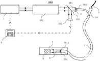
如图1至图7所示,根据本发明实施例的利用超快激光供血管腔内治疗的装置1000,包括超快激光器1、光纤导管2、光纤耦合模块3和手术辅助结构4;其中,超快激光器1用于产生并输出超快激光脉冲(如图1中实线箭头所示);光纤耦合模块3设置在光纤导管2的输入端2011处,用于耦合超快激光器1输出的超快激光脉冲并将超快激光脉冲传输给光纤导管2的传导光纤束201(如图4和图5所示),传导光纤束201用于接收光纤耦合模块3输给的超快激光脉冲并传输至光纤导管2的输出端2013,由光纤导管2的输出端2013向前输出超快激光脉冲以对血管腔A内病变B(如血栓或斑块)进行辐射消蚀(如图1和图2所示);手术辅助结构4用于设置在光纤导管2的空腔结构202中,将光纤导管2引导至血管腔A内病变B处,以及用于向血管腔A内病变B处输送冷却液体、造影剂或/和药物(如图1和图2所示)。As shown in FIG. 1 to FIG. 7 , an
具体地,超快激光器1作为高能光源,可以产生并输出超快激光脉冲。超快激光器1输出的超快激光脉冲具备皮秒、飞秒量级的脉冲宽度和极高的瞬时峰值功率,可以与生物组织作用产生等离子体效应进而对生物组织进行高效汽化消蚀,从而很好地满足血管腔A内减容的医疗需求。例如当超快激光脉冲的波长为中波红外、近红外及其二倍频和三倍频等多种波段,作用于生物组织时可以产生等离子体等多种效应,进而对生物组织进行高效汽化消蚀。Specifically, as a high-energy light source, the
光纤耦合模块3设置在光纤导管2的输入端2011处,用于耦合超快激光器1输出的超快激光脉冲并将超快激光脉冲传输给光纤导管2的传导光纤束201,也就是说,通过设置光纤耦合模块3,可以使得超快激光器1输出的超快激光脉冲能够适配地进入传导光纤束201中,减少超快激光脉冲的能量损失,提高超快激光脉冲的消蚀效率。The optical
传导光纤束201用于接收光纤耦合模块3输给的超快激光脉冲并传输至光纤导管2的输出端2013,由光纤导管2的输出端2013向前输出超快激光脉冲以对血管腔A内病变B进行辐射消蚀。具体的,传导光纤束201的作用主要是传导超快激光脉冲,使得超快激光脉冲能够近距离直接照射在血管腔A内病变B上,因此,光纤导管2在使用时会被插入血管腔A内,光纤导管2的输出端2013会与病变B直接接触,然后利用光纤导管2的输出端2013输出的超快脉冲激光直接照射病变B,对血管腔A内病变B进行辐射消蚀,消蚀效率高,且对周围组织几乎无损伤;通过光纤导管2将超快激光脉冲输送至对血管腔A内病变B处对病变B进行辐射消蚀,相比于传统药物和手术治疗方法,具备高度的精准性且对辐照周围组织基本无热损伤,可实现安全高效的血管腔A内消蚀减容效果。The conducting
手术辅助结构4用于设置在光纤导管2的空腔结构202中,将光纤导管2引导至血管腔A内病变B处。在使用时,手术辅助结构4的前端会伸入到血管腔A内病变B处,然后光纤导管2沿着手术辅助结构4伸入到血管腔A内,直到输出端2013触碰到血管腔A内病变B处,然后利用超快激光脉冲对病变B进行消蚀,不会损伤血管腔A内其他组织;也就是说,手术辅助结构4可以引导光纤导管2快速准确方便地到达病变B处,显著了降低操作者的操作难度,便于操作者的实际消蚀操作和控制,具备较强的普适性。The surgical
手术辅助结构4还可用于向血管腔A内病变B处输送冷却液体、造影剂或/和药物。利用手术辅助结构4向血管腔A内病变B处输送冷却液体(例如生理盐水)用于消除消蚀过程可能产生的热效应;利用手术辅助结构4向血管腔A内病变B处输送造影剂以对血管进行造影,从而方便对血管腔A内的病变B情况或消蚀情况进行观察;利用手术辅助结构4向血管腔A内病变B处输送药物,例如促进血管壁修复等功效的药物,以获得更好的手术治疗效果。The surgical
根据本发明实施例的利用超快激光供血管腔内治疗的装置1000,具有如下优点,第一、通过光纤导管2将超快激光脉冲输送至血管腔A内病变B处(例如血栓和斑块)进行辐射消蚀,相比于传统药物和手术治疗方法,具备高度的精准性且对辐照周围组织基本无热损伤,可实现安全高效的血管腔A内消蚀减容效果;第二、采用的超快激光器1便于集成和开发,几乎无需维护,使用成本低,光束能量稳定;第三、使用光纤耦合模块3对超快激光脉冲进行激光能量的耦合传输,使得超快激光脉冲能够适配地进入传导光纤束201中,减少超快激光脉冲的能量损失,提高超快激光脉冲的消蚀效率;第四、手术辅助结构4的设置可显著降低操作者的操作难度,便于操作者的实际消蚀操作和控制,具备较强的普适性。The
根据本发明的一些实施例,超快激光器1为固体超快激光器或光纤超快激光器,固体超快激光器和光纤超快激光器均能产生超快激光脉冲,该超快激光脉冲具备皮秒、飞秒量级的脉冲宽度和极高的瞬时峰值功率,可以与生物组织作用产生等离子体效应进而对生物组织进行高效汽化消蚀,从而很好地满足血管腔A内减容的医疗需求。固体超快激光器或光纤超快激光器便于集成和开发,寿命长,几乎无需维护,使用成本低,光束能量稳定,临床应用效果更为可靠。优选的,光纤超快激光器1为光纤飞秒脉冲激光器,波长为1030-1035nm,输出激光光束能量稳定,且设备紧凑,寿命长,几乎无需维护。According to some embodiments of the present invention, the
根据本发明的一些实施例,光纤耦合模块3采用自由空间耦合模块301或光纤模式耦合模块303。也就是说,采用自由空间耦合模块301或光纤模式耦合模块303均可以使得超快激光器1输出的超快激光脉冲能够适配地进入传导光纤束201中,减少了超快激光脉冲的能量损失,提高超快激光脉冲的消蚀效率。同时,自由空间耦合模块301可以降低操作者的操作难度低,便于操作者的实际消蚀操作和控制,具备较强的普适性。当光纤耦合模块3为光纤模式耦合模块303时,光纤模式耦合模块303采用光纤模式耦合器的耦合方式进行能量传输,实现了本发明实施例的利用超快激光供血管腔内治疗的装置1000整体的全光纤化,装置结构紧凑,便于集成,制作难度较低。According to some embodiments of the present invention, the
根据本发明的一些实施例,如图1所示,当光纤耦合模块3采用自由空间耦合模块301时,利用超快激光供血管腔内治疗的装置1000还包括准直扩束光路302,准直扩束光路302设置在超快激光器1与自由空间耦合模块301之间,用于对超快激光器1输出的超快激光脉冲进行处理,使得处理后的超快激光脉冲与自由空间耦合模块301适配耦合。需要说明的是,准直扩束光路302用于使从超快激光器1输出超快激光脉冲光束,准直且具有较好的平行性,照射到自由空间耦合模块301上的光场均匀,这样,从准直扩束光路302输出的超快激光脉冲经过自由空间耦合模块301的耦合后,超快激光脉冲的聚焦光斑会位于自由空间耦合模块301的焦平面上,避免了聚焦光斑的位置发生变化。当将传导光纤束201的输入端2011设置在自由空间耦合模块301的焦平面上,且传导光纤束201中的光纤端面与聚焦光斑一一对应时,就实现了对超快激光脉冲的高效匹配耦合传输;设置准直扩束光路302也方便对超快激光脉冲的激光光束孔径的大小进行调整,使得超快激光脉冲耦合时的孔径角不超过光纤导管2的传导光纤束201中光纤的数值孔径,激光模场面积和光纤导管2的传导光纤束201中光纤纤芯的传导模场面积相匹配,满足模式耦合条件,实现更高效的耦合。According to some embodiments of the present invention, as shown in FIG. 1 , when the optical
根据本发明的一些实施例,准直扩束光路302包括第一光隔离器,第一光隔离器用于防止后向散射光返回进入超快激光器1,对超快激光器1起到保护作用,避免后向散射光对超快激光器1造成损害,延长超快激光器1的使用寿命。According to some embodiments of the present invention, the collimated beam expansion
根据本发明的一些实施例,自由空间耦合模块301为平面聚焦阵列的光学元件,可以理解的是,平面聚焦阵列的光学元件可以将超快脉冲激光汇聚在平面聚焦阵列的光学元件的各个聚焦点上,且各个聚焦点与光纤导管2的传导光纤束201中的各个光纤端面位置一一对应,使得超快激光器1输出的超快激光脉冲能够适配地进入传导光纤束201中,减少了超快激光脉冲的能量损失,提高超快激光脉冲的消蚀效率。According to some embodiments of the present invention, the free
根据本发明的一些实施例,自由空间耦合模块301为微透镜阵列或微纳光学器件。微透镜阵列或微纳光学器件均可以将超快脉冲激光汇聚在各自的各个聚焦点上,且各个聚焦点与光纤导管2的传导光纤束201中的各个光纤端面位置一一对应,使得超快激光器1输出的超快激光脉冲能够适配地进入传导光纤束201中,减少了超快激光脉冲的能量损失,提高超快激光脉冲的消蚀效率。具体地,微透镜阵列相当于多个排列在同一平面内焦距相同的小透镜,超快激光脉冲形成的光束入射微透镜阵列后,会在微透镜阵列焦平面上形成一系列聚焦光斑,也就是说每个小透镜都有自己的聚焦光斑,这些聚焦光斑与传导光纤束201中的多个光纤一一对应,以将超快激光器1输出的超快激光脉冲对应耦合进入传导光纤束201中的多个光纤中。According to some embodiments of the present invention, the free-
根据本发明的一些实施例,当光纤耦合模块3采用光纤模式耦合模块303时,光纤模式耦合模块303包括与超快激光器1相连的激光尾纤输出端3031、第二光纤隔离器3032,激光尾纤输出端3031、第二光纤隔离器3032和传导光纤束201的输入端2011按顺序匹配焊接,第二光纤隔离器3032用于防止后向散射光返回进入超快激光器1。如图2所示,激光尾纤输出端3031、第二光纤隔离器3032和传导光纤束201的输入端2011按顺序匹配焊接,使得超快激光器1输出的超快激光脉冲能够适配地进入传导光纤束201中,减少了超快激光脉冲的能量损失,提高超快激光脉冲的消蚀效率。其中,当激光尾纤输出端3031和传导光纤束201的输入端2011的光纤结构相同时,激光尾纤输出端3031和传导光纤束201的输入端2011直接焊接;当激光尾纤输出端3031和传导光纤束201的输入端2011的光纤结构不相同时,传导光纤束201的输入端2011通过拉锥、焊接等过程形成类似于光纤合束器的结构后,再与激光尾纤输出端3031焊接,实现和激光尾纤输出端3031的模式匹配,提高耦合效率。第二光纤隔离器3032对超快激光器1起到保护作用,避免后向散射光对超快激光器1造成损害,延长超快激光器1的使用寿命。According to some embodiments of the present invention, when the
根据本发明的一些实施例,传导光纤束201为低损耗光纤束,以提高超快激光脉冲的传导效率,减少超快激光脉冲在传输过程中的损耗,同时也保证了本发明的利用超快激光供血管腔内治疗的装置1000输出的超快激光脉冲能量的稳定。According to some embodiments of the present invention, the conducting
根据本发明的一些实施例,低损耗光纤束采用普通阶跃折射率光纤、光子晶体光纤、微结构光纤、空心光纤中的一种或多种构成,可以理解的是,普通阶跃折射率光纤、光子晶体光纤、微结构光纤、空心光纤均具有可以低损耗传输超快激光脉冲的特点,在实际应用中可以根据需要进行选择。另外,低损耗光纤束还可以包括内含多模晶体光纤束,内含多模晶体光纤束的耦合难度低,激光能量衰减少。According to some embodiments of the present invention, the low-loss fiber bundle is constituted by one or more of ordinary step-index fibers, photonic crystal fibers, microstructured fibers, and hollow-core fibers. It can be understood that ordinary step-index fibers , photonic crystal fiber, microstructure fiber, and hollow-core fiber all have the characteristics of low-loss transmission of ultrafast laser pulses, and can be selected according to needs in practical applications. In addition, the low-loss optical fiber bundle may also include a multi-mode crystal optical fiber bundle, which has low coupling difficulty and reduced laser energy attenuation.
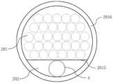
根据本发明的一些实施例,传导光纤束201中的光纤在输入端2011处呈矩形排列形式或圆形排列形式并采用第一边框2014固定,以便于进行耦合操作,例如如图3所示,传导光纤束201中的光纤排列形式为m*n的矩形,m的取值范围为8~10,n的取值范围为9~10。传导光纤束201中的光纤在输出端2013处呈环形排列形式(如图4所示)或偏心排列形式(如图5所示)并采用内边框2015和外边框2016进行固定,以及采用保护窗口204进行保护。内边框2015内侧为空腔结构202,以留出手术辅助结构4的设置空间,保护窗口204的设置用于将位于输出端2013的光纤密封在内边框2015和外边框2016之间,保护光纤不受污染,并且超快激光脉冲可以透过保护窗口204射出。可以理解的是,输入端2011处和输出端2013处的光纤数量相等。According to some embodiments of the present invention, the optical fibers in the conducting
优选的,传导光纤束201中的光纤纤芯直径100-125μm,光纤外的包层直径为125-150μm,实际应用性强,耦合方便。Preferably, the diameter of the fiber core in the conducting
根据本发明的一些实施例,如图1和图2所示,本发明实施例的利用超快激光供血管腔内治疗的装置1000还包括激光检测模块5和控制模块6;激光检测模块5用于从超快激光器1输出的超快激光脉冲中分出小部分光束进行激光参数检测并将检测的数据反馈回控制模块6。可以理解的是,激光检测模块5会根据小部分光束的激光参数以及小部分光束占超快激光脉冲的比例,来计算出超快激光脉冲的实际激光参数,然后将检测的数据反馈会控制模块6,从而控制模块6可以显示检测获得的数据,和/或根据检测的数据对本发明的利用超快激光供血管腔内治疗的装置1000进行控制。控制模块6用于控制利用超快激光供血管腔内治疗的装置1000的开关运行和模式切换,例如工作模式或修正模式,并根据激光检测模块5反馈的数据设定自动或手动方式修正激光参数,以保证激光消蚀过程的安全高效的进行。其中自动方式为由内部电路和程序对反馈的数据进行处理,自动修正超快激光器1错误的激光参数;手动方式为根据显示界面601显示的反馈数据,手动修正超快激光器1错误的激光参数。According to some embodiments of the present invention, as shown in FIG. 1 and FIG. 2 , the
根据本发明的一些实施例,如图1所示,当光纤耦合模块3采用自由空间耦合模块301时,激光检测模块5包括分束器501和第一探测器502;分束器501用于从超快激光器1输出的超快激光脉冲中分出小部分光束;例如分束器501可以通过在一定角度下反射部分超快激光脉冲至第一探测器502的方式,实现分出小部分光束的过程。优选的,分束器501的分光比可为99/1。第一探测器502用于对分束器501分出的小部分光束进行激光参数检测并反馈回控制模块6,以实现对超快激光脉冲的激光参数的检测,有效降低了消蚀操作难度并提高对病变进行消蚀过程的安全性。可以理解的是,第一探测器502会根据分束器501的分光比计算超快激光脉冲的实际激光参数,并反馈到装置控制模块6,为自动或手动方式修正超快激光器1的激光参数提供数据。具体地,第一探测器502可以为能量计或第一光功率计。According to some embodiments of the present invention, as shown in FIG. 1, when the
如图2所示,当光纤耦合模块3采用光纤模式耦合模块303时,激光检测模块5包括检测光纤503和第二探测器504,检测光纤503的一端和传导光纤束201的输入端2011一起与激光尾纤输出端3031匹配焊接,检测光纤503的另一端连接至第二探测器504,第二探测器504根据检测光纤503中的光纤个数占检测光纤503中的光纤个数和传导光纤束201中的光纤个数之和的比例计算光路中的实际激光参数并反馈回控制模块6,以实现对超快激光器1输出的超快激光脉冲的激光参数的检测,有效降低了消蚀操作难度并提高对病变进行消蚀过程的安全性。在一个具体的例子中,可以将传导光纤束201中的2~3根光纤取出作为检测光纤503,并连接到第二探测器504,然后根据检测光纤503中的光纤个数占传导光纤束201中的光纤总个数的比例计算光路中的激光参数,并反馈到装置控制模块6。第二探测器504可以为第二光功率计。As shown in FIG. 2 , when the
根据本发明的一些实施例,如图8所示,控制模块6包括显示界面601和按键界面602;显示界面601用于显示参数;按键界面602用于设定参数、“工作/修正”模式切换以及“修正”模式下“自动/手动”模式切换,以控制超快激光器1输出超快激光脉冲以及根据激光检测模块5反馈的数据进行自动或手动方式的参数修正,保证超快激光器1的准确和正常使用。具体地,控制模块6的操作界面如图8所示,显示界面601可以为液晶显示界面,按键界面602包括数字按键、“功率”按键、“重复频率”按键、“确认”按键、“开/关”按键、“输出”按键、“工作/修正”按键和“自动/手动”按键,按下和抬起表示不同的功能或操作模式。将数字输入后点击“确认”按键即可对激光参数进行输入设定;“开/关”按键按下代表控制模块6开机,按键抬起代表控制模块6关机;“输出”按键按下代表超快激光脉冲输出,按键抬起代表停止激光脉冲输出;“工作/修正”按键按下代表选择“修正”模式,同时“自动/手动”按键指示灯亮起,按键抬起代表选择“工作”模式,同时“自动/手动”按键指示灯熄灭;“自动/手动”按键按下代表选择“手动”模式,按键抬起代表选择“自动”模式,控制方式简单方便,便于操作。According to some embodiments of the present invention, as shown in FIG. 8 , the
在具体使用本发明实施例的利用超快激光供血管腔内治疗的装置1000时,如图9所示,首先将控制模块6开机,控制模块6开机后会不断检测超快激光器1是否开机,若超快激光器1开机,则进行控制操作,选择“修正”或者“工作”模式;选择“修正”模式后,进一步对“自动”或者“手动”模式进行选择,选择“自动”模式后,使用按键界面602设定激光参数并输出超快激光脉冲,通过内部电路和程序处理反馈数据,对错误激光参数进行自动修正,选择“手动”模式后,使用按键界面602设定激光参数并输出激光脉冲,根据显示界面601显示的反馈数据,使用按键界面602修正错误的激光参数。When specifically using the
根据本发明的一些实施例,“自动”模式为有内部电路和程序对激光检测模块5反馈的数据进行处理,自动修正错误的激光参数;“手动”模式为根据显示界面601显示的激光检测模块5反馈的数据,通过使用按键界面602手动修正错误的激光参数,从而操作人员可以采用不同的方式对错误的激光参数进行修正,以适应实际中的需要,适用范围广。According to some embodiments of the present invention, the “automatic” mode is that the data fed back by the
根据本发明的一些实施例,如图1和图2所示,光纤导管2上在靠近输出端2013的部位上设有合并接口203,合并接口203与空腔结构202连通,从而手术辅助结构4可以通过合并接口203进入到空腔结构202中;如图6和图7所示,手术辅助结构4包括导丝401和输液管402,导丝401和输液管402用于从合并接口203进入空腔结构202中。导丝401用于将光纤导管2引导至血管腔A内病变B处,使用时,首先将导丝401从合并接口203插入到空腔结构202中,然后光纤导管2的输出端2013便可以沿着导丝401移动,准确快速地到达病变处。输液管402用于向血管腔A内病变B处输送冷却液体、造影剂或/和药物。例如利用输液管402用于向照射区域喷射生理盐水以冷却可能出现的热效应,输注碘造影剂并在透视下观察血管腔A内病变B情况,还可以利用输液管401输送药物以满足手术需要,提高手术治疗效果。According to some embodiments of the present invention, as shown in FIG. 1 and FIG. 2 , the
根据本发明的一些实施例,光纤导管2的输出端2013的端面为球面或平面等形状,从而可以避免因输出端2013的端面存在缺陷超快激光脉冲发生严重的散射的情况,降低超快激光脉冲的能量损耗,保证输出端2013的出光效果。优选的,光纤导管2的输出端2013的端面为球面,这样,还可以降低从输出端2013输出的超快激光脉冲的发散角,提高照射的能量密度。According to some embodiments of the present invention, the end face of the
根据本发明的一些实施例,超快激光脉冲的重复频率可根据实际辐射消蚀要求进行调整。According to some embodiments of the present invention, the repetition rate of the ultrafast laser pulses can be adjusted according to actual radiation ablation requirements.
下面给出本发明的一个具体的例子。A specific example of the present invention is given below.
在该具体的例子中,利用超快激光供血管腔内治疗的装置1000,包括超快激光器1、光纤导管2、光纤耦合模块3、手术辅助结构4、激光检测模块5和控制模块6;其中,超快激光器1用于产生并输出超快激光脉冲;光纤耦合模块3设置在光纤导管2的输入端2011处,用于耦合超快激光器1输出的超快激光脉冲并将超快激光脉冲传输给光纤导管2的传导光纤束201,传导光纤束201用于接收光纤耦合模块3输给的超快激光脉冲并传输至光纤导管2的输出端2013,由光纤导管2的输出端2013向前输出超快激光脉冲以对血管腔A内病变B进行辐射消蚀,传导光纤束201中的光纤在输入端2011处呈矩形排列形式并采用第一边框2014固定,传导光纤束201中的光纤在输出端2013处呈环形排列形式并采用内边框2015和外边框2016进行固定以及采用保护窗口204进行保护。手术辅助结构4用于设置在光纤导管2的空腔结构202中,将光纤导管2引导至血管腔A内病变B处,以及用于向血管腔A内病变B处输送冷却液体、造影剂或/和药物,激光检测模块5用于从超快激光器1输出的超快激光脉冲中分出小部分光束进行激光参数检测并将检测的数据反馈回控制模块6;控制模块6用于控制利用超快激光供血管腔A内治疗的装置的开关运行和模式切换,并根据激光检测模块5反馈的数据设定自动或手动方式修正激光参数。In this specific example, the
控制模块6包括显示界面601和按键界面602;显示界面601用于显示参数;按键界面602用于设定参数、“工作/修正”模式切换以及“修正”模式下“自动/手动”模式切换,以控制超快激光器1输出超快激光脉冲以及根据激光检测模块5反馈的数据进行自动或手动方式的参数修正。“自动”模式为有内部电路和程序对激光检测模块5反馈的数据进行处理,自动修正错误的激光参数;“手动”模式为根据显示界面601显示的激光检测模块5反馈的数据,通过使用按键界面602手动修正错误的激光参数。The
光纤导管2上在靠近输出端2013的部位上设有合并接口203,合并接口203与空腔结构202连通;手术辅助结构4包括导丝401和输液管402,导丝401和输液管402用于从合并接口203进入空腔结构202中,导丝401用于将光纤导管2引导至血管腔A内病变B处,输液管402用于向血管腔A内病变B处输送冷却液体、造影剂或/和药物。The
该实施例的使用步骤包括,The steps of using this embodiment include,
步骤S1:超快激光器1开机,控制模块6开机,选择“修正”模式,使用按键界面602设定激光参数,输出超快激光脉冲,使用激光检测模块5对实际输出的激光参数进行检测,并反馈回控制模块6进行参数修正,停止输出超快激光;Step S1: the
步骤S2:将手术辅助结构4通过微创介入的方式沿人体血管内部抵达血管腔A内病变B,如血栓和斑块处;Step S2: The surgical
步骤S3:将光纤导管2套在手术辅助结构4上,并沿手术辅助结构4将传导光纤束201的输出端2013伸入血管腔A内,并送至血管腔A内血栓和斑块处;Step S3: sleeve the
步骤S4:选择“工作”模式,使用控制模块6的按键界面602对超快激光器1的参数进行设定,输出超快激光脉冲对血管腔A内血栓和斑块进行辐照消蚀;Step S4: select the "work" mode, use the
步骤S5:在消蚀过程中,手术辅助结构4先推进一小段距离,光纤导管2再按实际消蚀速度逐步推进,如此循环往复;Step S5: During the ablation process, the surgical
步骤S6:通过手术辅助结构4中的输液管402输入造影剂,观察血管造影,若消蚀难以进行或者血流通路尚未恢复,可参照激光检测模块5反馈到显示界面601的数值,使用控制模块6的按键界面602对激光参数进行微调或者再进行一段时间的照射消蚀;若血流通路恢复,则停止输出超快激光,控制模块6关机,超快激光器1关机,先撤出手术辅助结构4,后撤出光纤导管2。Step S6: Input the contrast agent through the
该具体的例子的利用超快激光供血管腔内治疗的装置,具有如下优点,第一、通过光纤导管2将超快激光脉冲输送至血管腔A内病变B处(例如血栓和斑块)进行辐射消蚀,相比于传统药物和手术治疗方法,具备高度的精准性且对辐照周围组织基本无热损伤,可实现安全高效的血管腔A内消蚀减容效果;第二、采用的超快激光器1便于集成和开发,几乎无需维护,使用成本低,光束能量稳定;第三、使用光纤耦合模块3对超快激光脉冲进行激光能量的耦合传输,使得超快激光脉冲能够适配地进入传导光纤束201中,减少超快激光脉冲的能量损失,提高超快激光脉冲的消蚀效率;第四、手术辅助结构4的设置可显著降低操作者的操作难度,便于操作者的实际消蚀操作和控制,具备较强的普适性。该具体的实施例的其他对应结构的作用和优点与上文中的相同,在此不再赘述。The device for endovascular treatment using ultrafast laser in this specific example has the following advantages. First, the ultrafast laser pulse is delivered to the lesion B (such as thrombus and plaque) in the vascular cavity A through the
在本说明书的描述中,参考术语“一个实施例”、“一些实施例”、“示意性实施例”、“示例”、“具体示例”、或“一些示例”等的描述意指结合该实施例或示例描述的具体特征、结构、或者特点包含于本发明的至少一个实施例或示例中。在本说明书中,对上述术语的示意性表述不一定指的是相同的实施例或示例。而且,描述的具体特征、结构、或者特点可以在任何的一个或多个实施例或示例中以合适的方式结合。In the description of this specification, reference to the terms "one embodiment," "some embodiments," "exemplary embodiment," "example," "specific example," or "some examples", etc., is meant to incorporate the embodiments A particular feature, structure, or characteristic described by an example or example is included in at least one embodiment or example of the present invention. In this specification, schematic representations of the above terms do not necessarily refer to the same embodiment or example. Furthermore, the particular features, structures, or characteristics described may be combined in a suitable manner in any one or more embodiments or examples.
尽管已经示出和描述了本发明的实施例,本领域的普通技术人员可以理解:在不脱离本发明的原理和宗旨的情况下可以对这些实施例进行多种变化、修改、替换和变型,本发明的范围由权利要求及其等同物限定。Although embodiments of the present invention have been shown and described, it will be understood by those of ordinary skill in the art that various changes, modifications, substitutions and alterations can be made in these embodiments without departing from the principles and spirit of the invention, The scope of the invention is defined by the claims and their equivalents.
Claims (16)
Translated fromChinesePriority Applications (1)
| Application Number | Priority Date | Filing Date | Title |
|---|---|---|---|
| CN202210334439.2ACN114886556A (en) | 2022-03-30 | 2022-03-30 | Device for blood intraluminal treatment using ultrafast laser |
Applications Claiming Priority (1)
| Application Number | Priority Date | Filing Date | Title |
|---|---|---|---|
| CN202210334439.2ACN114886556A (en) | 2022-03-30 | 2022-03-30 | Device for blood intraluminal treatment using ultrafast laser |
Publications (1)
| Publication Number | Publication Date |
|---|---|
| CN114886556Atrue CN114886556A (en) | 2022-08-12 |
Family
ID=82714880
Family Applications (1)
| Application Number | Title | Priority Date | Filing Date |
|---|---|---|---|
| CN202210334439.2APendingCN114886556A (en) | 2022-03-30 | 2022-03-30 | Device for blood intraluminal treatment using ultrafast laser |
Country Status (1)
| Country | Link |
|---|---|
| CN (1) | CN114886556A (en) |
Cited By (1)
| Publication number | Priority date | Publication date | Assignee | Title |
|---|---|---|---|---|
| CN117860371A (en)* | 2023-11-23 | 2024-04-12 | 中科量光(合肥)医疗科技有限公司 | Multi-wavelength and three-dimensional steering laser scalpel optical fiber device |
Citations (6)
| Publication number | Priority date | Publication date | Assignee | Title |
|---|---|---|---|---|
| CN101247027A (en)* | 2007-02-15 | 2008-08-20 | 昂纳明达数字显示技术(深圳)有限公司 | Red laser module for laser display |
| CN101897619A (en)* | 2010-07-12 | 2010-12-01 | 中国科学院长春光学精密机械与物理研究所 | Long-wavelength high-power semiconductor laser comprehensive treatment instrument |
| CN102512206A (en)* | 2011-12-13 | 2012-06-27 | 苏州生物医学工程技术研究所 | Intravenous ultrasound-based ultrasonic diagnosis and photoacoustic therapy device and therapeutic method thereof |
| CN105636540A (en)* | 2013-10-15 | 2016-06-01 | 尼普洛株式会社 | ablation system and ablation device |
| WO2021046643A1 (en)* | 2019-09-11 | 2021-03-18 | North Star Specialists Inc. | Catheter, sheath or dilator for heart valve decalcification treatment and method of use thereof |
| CN113057732A (en)* | 2021-03-25 | 2021-07-02 | 哈尔滨医科大学 | A laser ablation catheter |
- 2022
- 2022-03-30CNCN202210334439.2Apatent/CN114886556A/enactivePending
Patent Citations (6)
| Publication number | Priority date | Publication date | Assignee | Title |
|---|---|---|---|---|
| CN101247027A (en)* | 2007-02-15 | 2008-08-20 | 昂纳明达数字显示技术(深圳)有限公司 | Red laser module for laser display |
| CN101897619A (en)* | 2010-07-12 | 2010-12-01 | 中国科学院长春光学精密机械与物理研究所 | Long-wavelength high-power semiconductor laser comprehensive treatment instrument |
| CN102512206A (en)* | 2011-12-13 | 2012-06-27 | 苏州生物医学工程技术研究所 | Intravenous ultrasound-based ultrasonic diagnosis and photoacoustic therapy device and therapeutic method thereof |
| CN105636540A (en)* | 2013-10-15 | 2016-06-01 | 尼普洛株式会社 | ablation system and ablation device |
| WO2021046643A1 (en)* | 2019-09-11 | 2021-03-18 | North Star Specialists Inc. | Catheter, sheath or dilator for heart valve decalcification treatment and method of use thereof |
| CN113057732A (en)* | 2021-03-25 | 2021-07-02 | 哈尔滨医科大学 | A laser ablation catheter |
Cited By (1)
| Publication number | Priority date | Publication date | Assignee | Title |
|---|---|---|---|---|
| CN117860371A (en)* | 2023-11-23 | 2024-04-12 | 中科量光(合肥)医疗科技有限公司 | Multi-wavelength and three-dimensional steering laser scalpel optical fiber device |
Similar Documents
| Publication | Publication Date | Title |
|---|---|---|
| US20240407845A1 (en) | System for tissue ablation using pulsed laser | |
| Fried et al. | Advances in laser technology and fibre-optic delivery systems in lithotripsy | |
| US5843073A (en) | Infrared laser catheter system | |
| US6159203A (en) | Infrared laser catheter system | |
| US6213998B1 (en) | Laser surgical cutting probe and system | |
| CN114469336B (en) | Laser output device and laser ablation system | |
| CN115553918A (en) | Pulsed laser ablation system | |
| CN114431955B (en) | Ultra-fast laser galvanometer scanning coupling method | |
| CN114668493A (en) | System and method for ultrafast laser treatment in blood vessel cavity | |
| CN114886556A (en) | Device for blood intraluminal treatment using ultrafast laser | |
| WO2020231975A1 (en) | Methods and apparatus for high-speed and high-aspect ratio laser subtractive material processing | |
| Bidinger et al. | A feasibility study on femtosecond laser thrombolysis | |
| US20250281221A1 (en) | Intravascular lithotripsy catheter system with controller and graphical user interface | |
| Qiu et al. | Near infrared femtosecond laser ablation of urinary calculi in water | |
| CN119632669A (en) | A visual fiber ablation system | |
| Bussiere et al. | Intraoperative XeCl Excimer Laser Coronary Artery Endarterectomy: Clinical Experience. | |
| BUSSIERE et al. | J. zyxwvutsrqponmlkjihgfedcbaZ | |
| WO2025097269A1 (en) | Optical fiber combining-coupled ultraviolet laser ablation system | |
| Fried | Erbium: YAG Laser Incision of Urethral Structures for Treatment of Urinary Incontinence After Prostate Cancer Spray | |
| Hutchens | Novel fiber optic tip designs and devices for laser surgery | |
| Hutchens et al. | Comparison of detachable and tapered fiber optic tips for use in thulium fiber laser lithotripsy | |
| Scott et al. | Thulium fiber laser lithotripsy | |
| Kotsifaki et al. | Fibers and fiber end sealing caps for Er: YAG laser ablation | |
| Avrillier et al. | Intraoperative XeCl excimer laser coronary artery endarterectomy: one-year follow up in ten patients and technical improvement of the method |
Legal Events
| Date | Code | Title | Description |
|---|---|---|---|
| PB01 | Publication | ||
| PB01 | Publication | ||
| SE01 | Entry into force of request for substantive examination | ||
| SE01 | Entry into force of request for substantive examination |