CN114879121A - Method, device, storage medium and device for detecting wrong wiring of smart electric energy meter - Google Patents
Method, device, storage medium and device for detecting wrong wiring of smart electric energy meterDownload PDFInfo
- Publication number
- CN114879121A CN114879121ACN202210601005.4ACN202210601005ACN114879121ACN 114879121 ACN114879121 ACN 114879121ACN 202210601005 ACN202210601005 ACN 202210601005ACN 114879121 ACN114879121 ACN 114879121A
- Authority
- CN
- China
- Prior art keywords
- voltage
- energy meter
- phasor
- current
- phase
- Prior art date
- Legal status (The legal status is an assumption and is not a legal conclusion. Google has not performed a legal analysis and makes no representation as to the accuracy of the status listed.)
- Pending
Links
Images


Classifications
- G—PHYSICS
- G01—MEASURING; TESTING
- G01R—MEASURING ELECTRIC VARIABLES; MEASURING MAGNETIC VARIABLES
- G01R35/00—Testing or calibrating of apparatus covered by the other groups of this subclass
- G01R35/04—Testing or calibrating of apparatus covered by the other groups of this subclass of instruments for measuring time integral of power or current
- G—PHYSICS
- G01—MEASURING; TESTING
- G01R—MEASURING ELECTRIC VARIABLES; MEASURING MAGNETIC VARIABLES
- G01R31/00—Arrangements for testing electric properties; Arrangements for locating electric faults; Arrangements for electrical testing characterised by what is being tested not provided for elsewhere
- G01R31/50—Testing of electric apparatus, lines, cables or components for short-circuits, continuity, leakage current or incorrect line connections
- G01R31/55—Testing for incorrect line connections
- Y—GENERAL TAGGING OF NEW TECHNOLOGICAL DEVELOPMENTS; GENERAL TAGGING OF CROSS-SECTIONAL TECHNOLOGIES SPANNING OVER SEVERAL SECTIONS OF THE IPC; TECHNICAL SUBJECTS COVERED BY FORMER USPC CROSS-REFERENCE ART COLLECTIONS [XRACs] AND DIGESTS
- Y04—INFORMATION OR COMMUNICATION TECHNOLOGIES HAVING AN IMPACT ON OTHER TECHNOLOGY AREAS
- Y04S—SYSTEMS INTEGRATING TECHNOLOGIES RELATED TO POWER NETWORK OPERATION, COMMUNICATION OR INFORMATION TECHNOLOGIES FOR IMPROVING THE ELECTRICAL POWER GENERATION, TRANSMISSION, DISTRIBUTION, MANAGEMENT OR USAGE, i.e. SMART GRIDS
- Y04S10/00—Systems supporting electrical power generation, transmission or distribution
- Y04S10/50—Systems or methods supporting the power network operation or management, involving a certain degree of interaction with the load-side end user applications
- Y04S10/52—Outage or fault management, e.g. fault detection or location
Landscapes
- Physics & Mathematics (AREA)
- General Physics & Mathematics (AREA)
- Remote Monitoring And Control Of Power-Distribution Networks (AREA)
Abstract
Description
Translated fromChinese技术领域technical field
本发明涉及智能电能表技术领域,尤其是涉及一种智能电能表的错接线检测方法、装置、存储介质及设备。The present invention relates to the technical field of smart electric energy meters, in particular to a method, device, storage medium and equipment for detecting wrong wiring of an intelligent electric energy meter.
背景技术Background technique
目前,相关技术人员在对智能电能表的错误接线情况进行分析时,首先需要采用相位伏安表、三相电能表现场检验仪、用电检查仪以及钳形万用表等多种检测仪器对智能电能表进行检测,进而对智能电能表的计量故障与存在的异常进行分析。At present, when the relevant technicians analyze the wrong wiring of the smart energy meter, they first need to use a variety of detection instruments such as phase voltammeter, three-phase electric energy meter field tester, power consumption tester and clamp multimeter. The meter is detected, and then the metering faults and existing anomalies of the smart energy meter are analyzed.
现有的智能电能表错误接线的分析方法需要计量、装表接电以及用电检查等相关技术人员利用仪器仪表进行检测,检测结果的准确度受相关技术人员的专业技能水平以及实践工作经验影响,由于检测人员的技能水平参差不齐,因此得到的检测结果以及分析结果准确度较低,并且在检测过程中存在较大的安全隐患。The existing method for analyzing the wrong wiring of smart electric energy meters requires relevant technical personnel such as measurement, meter installation and electricity inspection, and electricity inspection to use instruments and meters for detection. The accuracy of the detection results is affected by the professional skill level and practical work experience of the relevant technical personnel. , Due to the uneven skill level of the inspectors, the obtained inspection results and analysis results are less accurate, and there are greater safety hazards in the inspection process.
发明内容SUMMARY OF THE INVENTION
有鉴于此,本申请提供了一种智能电能表的错接线检测方法、装置、存储介质及设备,主要目的在于解决现有智能电能表错误接线的分析结果准确度不高,且存在安全隐患的技术问题。In view of this, the present application provides a method, device, storage medium and equipment for detecting wrong wiring of smart electric energy meters, the main purpose of which is to solve the problem that the analysis results of wrong wiring of existing smart electric energy meters are not high in accuracy and have potential safety hazards. technical problem.
根据本发明的第一个方面,提供了一种智能电能表的错接线检测方法,该方法包括:According to a first aspect of the present invention, a method for detecting wrong wiring of a smart electric energy meter is provided, the method comprising:
接收智能电能表上传的运行数据,并获取所述智能电能表的负荷特性;Receive the operation data uploaded by the smart energy meter, and obtain the load characteristics of the smart energy meter;
提取所述运行数据中的功率数据,并判断所述功率数据是否在预设功率数据范围内;extracting power data in the operating data, and judging whether the power data is within a preset power data range;
若所述功率数据不在所述预设功率数据范围内,则提取所述运行数据中的电压相序,并根据所述电压相序的相序类型生成电压相量图;If the power data is not within the preset power data range, extract the voltage phase sequence in the operation data, and generate a voltage phasor diagram according to the phase sequence type of the voltage phase sequence;
通过所述运行数据计算所述智能电能表内每一元件的电流相量,将所述每一元件的电流相量添加在所述电压相量图中,生成所述智能电能表的相量图谱;Calculate the current phasor of each element in the smart energy meter through the operating data, add the current phasor of each element to the voltage phasor diagram, and generate a phasor diagram of the smart energy meter ;
利用所述负荷特性确定所述相量图谱中每一元件的电压接入方式和每一元件的电流接入方式,并根据所述每一元件的电压接入方式和所述每一元件的电流接入方式,得到所述智能电能表的错接线类型。Using the load characteristic to determine the voltage access mode of each element and the current access mode of each element in the phasor map, and according to the voltage access mode of each element and the current access mode of each element The connection method is used to obtain the wrong wiring type of the smart energy meter.
可选地,所述根据所述电压相序的相序类型生成电压相量图,包括:Optionally, the generating a voltage phasor diagram according to the phase sequence type of the voltage phase sequence includes:
当所述电压相序的相序类型为正相序时,沿顺时针间隔120°依次添加所述智能电能表的各相电压,提取所述运行数据中每一元件的电压相量,并根据所述智能电能表的接线方式,添加所述每一元件的电压相量,得到电压相量图;When the phase sequence type of the voltage phase sequence is positive phase sequence, the voltages of each phase of the smart energy meter are sequentially added at 120° clockwise intervals, the voltage phasors of each element in the operating data are extracted, and the The wiring method of the smart energy meter, adding the voltage phasor of each element to obtain a voltage phasor diagram;
当所述电压相序的相序类型为逆相序时,沿逆时针间隔120°依次添加所述智能电能表的各相电压,提取所述运行数据中每一元件的电压相量,并根据所述智能电能表的接线方式,添加所述每一元件的电压相量,得到电压相量图。When the phase sequence type of the voltage phase sequence is reverse phase sequence, the voltages of each phase of the smart energy meter are sequentially added at 120° counterclockwise intervals, the voltage phasors of each element in the operating data are extracted, and the The wiring method of the smart energy meter is to add the voltage phasor of each element to obtain a voltage phasor diagram.
可选地,所述运行数据包括所述每一元件的电流值、有功功率、无功功率和功率因数;所述通过所述运行数据计算所述智能电能表内每一元件的电流相量,将所述每一元件的电流相量添加在所述电压相量图中,生成所述智能电能表的相量图谱,包括:Optionally, the operation data includes the current value, active power, reactive power and power factor of each element; the current phasor of each element in the smart energy meter is calculated by the operation data, Adding the current phasor of each element to the voltage phasor diagram to generate a phasor diagram of the smart energy meter, including:
通过所述每一元件的功率因数,计算每一元件的相位角数值;Calculate the phase angle value of each element through the power factor of each element;
根据所述每一元件的有功功率和无功功率,确定每一元件的相位角方向;Determine the phase angle direction of each element according to the active power and reactive power of each element;
根据所述每一元件的相位角数值和相位角方向,计算所述每一元件的电压相量与电流相量之间的位置关系和角度;According to the phase angle value and phase angle direction of each element, calculate the positional relationship and angle between the voltage phasor and the current phasor of each element;
根据所述每一元件的电压相量与电流相量之间的位置关系和角度以及所述每一元件的电流值,得到所述每一元件的电流相量;According to the positional relationship and angle between the voltage phasor and the current phasor of each element and the current value of each element, obtain the current phasor of each element;
将所述每一元件的电流相量添加在所述电压相量图中,生成所述智能电能表的相量图谱。The current phasor of each element is added to the voltage phasor diagram to generate a phasor diagram of the smart energy meter.
可选地,所述利用所述负荷特性确定所述相量图谱中每一元件的电压接入方式和每一元件的电流接入方式,包括:Optionally, the determining the voltage connection mode of each element and the current connection mode of each element in the phasor map by using the load characteristic includes:
根据所述智能电能表的负荷特性,得到所述每一元件的电流相量与所述智能电能表的相电压之间的理论位置关系和角度;According to the load characteristic of the smart energy meter, obtain the theoretical positional relationship and angle between the current phasor of each element and the phase voltage of the smart energy meter;
根据所述理论位置关系和角度,得到所述相量图谱中所述智能电能表的相电压的相别和所述每一元件的电流相量的相别;According to the theoretical position relationship and angle, obtain the phase difference of the phase voltage of the smart energy meter and the phase difference of the current phasor of each element in the phasor map;
根据所述相量图谱中所述智能电能表的相电压的相别和所述每一元件的电流相量的相别,确定所述每一元件的电压接线方式和所述每一元件的电流接线方式。Determine the voltage connection mode of each element and the current of each element according to the phase voltage of the smart energy meter and the current phasor of each element in the phasor map Wiring.
可选地,所述根据所述每一元件的电压接入方式和所述每一元件的电流接入方式,得到所述智能电能表的错接线类型,包括:Optionally, according to the voltage connection mode of each element and the current connection mode of each element, the wrong wiring type of the smart energy meter is obtained, including:
获取所述智能电能表内每一元件预设的电压接线方式和每一元件预设的电流接线方式;Acquire the preset voltage connection mode of each element and the preset current connection mode of each element in the smart energy meter;
将所述每一元件的电压接线方式与所述每一元件预设的电压接线方式进行比对,并将所述每一元件的电流接线方式与所述每一元件预设的电流接线方式进行比对,得到所述每一元件的电压接线方式的比对结果和所述每一元件的电流接线方式比对结果;Compare the voltage connection mode of each element with the preset voltage connection mode of each element, and compare the current connection mode of each element with the preset current connection mode of each element Comparing, obtaining the comparison result of the voltage connection mode of each element and the comparison result of the current connection mode of each element;
根据所述每一元件的电压接线方式的比对结果,和/或所述每一元件的电流接线方式比对结果,确定所述智能电能表的错接线类型,其中,所述错接线类型包括电压错接、电流错接、电压互感器极性反接和电流互感器极性反接。According to the comparison result of the voltage connection mode of each element and/or the comparison result of the current connection mode of each element, the type of wrong connection of the smart energy meter is determined, wherein the type of wrong connection includes: Voltage misconnection, current misconnection, reverse polarity of voltage transformer and reverse polarity of current transformer.
可选地,所述功率数据包括总功率因数和所述智能电能表内每一元件的功率因数;所述提取所述运行数据中的功率数据,并判断所述功率数据是否在预设功率数据范围内,包括:Optionally, the power data includes the total power factor and the power factor of each element in the smart energy meter; the extracting power data in the operating data, and judging whether the power data is within the preset power data range, including:
根据所述智能电能表的负荷特性,获取预设功率数据范围,其中,所述预设功率数据范围包括所述智能电能表在第I象限、第II象限、第III象限以及第IV象限的不同运行象限和不同负载功率因数角下所对应的总功率因数变化范围和所述每一元件的功率因数变化范围;Acquire a preset power data range according to the load characteristic of the smart electric energy meter, wherein the preset power data range includes the difference between the smart electric energy meter in quadrant I, quadrant II, quadrant III and quadrant IV The total power factor variation range and the power factor variation range of each element corresponding to the operating quadrant and different load power factor angles;
判断所述总功率因数是否在所述总功率因数变化范围内,并判断所述每一元件的功率因数是否在对应的所述每一元件的功率因数变化范围内;judging whether the total power factor is within the variation range of the total power factor, and judging whether the power factor of each element is within the corresponding power factor variation range of each element;
若所述总功率因数不在所述总功率因数的变化范围内,和/或所述每一元件的功率因数不在对应的所述每一元件的功率因数变化范围内,则判定所述功率数据不在所述预设功率数据范围内。If the total power factor is not within the variation range of the total power factor, and/or the power factor of each element is not within the corresponding variation range of the power factor of each element, it is determined that the power data is not within the variation range within the preset power data range.
可选地,所述提取所述运行数据中的功率数据,判断所述功率数据是否在预设功率数据范围内,还包括:Optionally, the extracting the power data in the operating data, and judging whether the power data is within a preset power data range, further includes:
若所述总功率因数在所述总功率因数的变化范围内,且所述每一元件的功率因数在对应的所述每一元件的功率因数变化范围内,则计算所述每一元件的功率因数的和值,并计算所述和值与所述总功率因数的比值,将所述比值与预设比值进行比对,其中,当所述智能电能表的接线方式为三相三线时,所述预设比值为
若所述比值与所述预设比值一致,则所述功率数据在所述预设功率数据范围内;If the ratio is consistent with the preset ratio, the power data is within the preset power data range;
若所述比值与所述预设比值不一致,则所述功率数据不在所述预设功率数据范围内。If the ratio is inconsistent with the preset ratio, the power data is not within the preset power data range.
根据本发明的第二个方面,提供了智能电能表的错接线检测装置,该装置包括:According to a second aspect of the present invention, a device for detecting wrong wiring of a smart electric energy meter is provided, the device comprising:
获取模块,用于接收智能电能表上传的运行数据,并获取所述智能电能表的负荷特性;an acquisition module, configured to receive the operation data uploaded by the smart energy meter, and acquire the load characteristics of the smart energy meter;
判断模块,用于提取所述运行数据中的功率数据,并判断所述功率数据是否在预设功率数据范围内;a judgment module, configured to extract the power data in the operation data, and judge whether the power data is within the preset power data range;
提取模块,用于若所述功率数据不在所述预设功率数据范围内,则提取所述运行数据中的电压相序,并根据所述电压相序的相序类型生成电压相量图;an extraction module, configured to extract the voltage phase sequence in the operation data if the power data is not within the preset power data range, and generate a voltage phasor diagram according to the phase sequence type of the voltage phase sequence;
计算模块,用于通过所述运行数据计算所述智能电能表内每一元件的电流相量,将所述每一元件的电流相量添加在所述电压相量图中,生成所述智能电能表的相量图谱;a calculation module, configured to calculate the current phasor of each element in the smart energy meter through the operating data, add the current phasor of each element to the voltage phasor diagram, and generate the smart electric energy The phasor diagram of the table;
输出模块,用于利用所述负荷特性确定所述相量图谱中每一元件的电压接入方式和每一元件的电流接入方式,并根据所述每一元件的电压接入方式和所述每一元件的电流接入方式,得到所述智能电能表的错接线类型。an output module, configured to use the load characteristic to determine the voltage access mode of each element and the current access mode of each element in the phasor map, and according to the voltage access mode of each element and the The current access mode of each element is used to obtain the wrong wiring type of the smart energy meter.
根据本发明的第三个方面,提供了一种存储介质,其上存储有计算机程序,程序被处理器执行时实现上述智能电能表的错接线检测方法。According to a third aspect of the present invention, there is provided a storage medium on which a computer program is stored, and when the program is executed by a processor, the above-mentioned method for detecting a wrong connection of a smart electric energy meter is implemented.
根据本发明的第四个方面,提供了一种计算机设备,包括存储器、处理器及存储在存储器上并可在处理器上运行的计算机程序,处理器执行程序时实现上述智能电能表的错接线检测方法。According to a fourth aspect of the present invention, a computer device is provided, comprising a memory, a processor, and a computer program stored in the memory and running on the processor, and the processor executes the program to realize the above-mentioned miswiring of the smart energy meter Detection method.
本发明提供的一种智能电能表的错接线检测方法、装置、存储介质及设备,首先接收智能电能表上传的运行数据,并获取智能电能表的负荷特性,其次提取运行数据中的功率数据,并判断功率数据是否在预设功率数据范围内,若功率数据不在预设功率数据范围内,则提取运行数据中的电压相序,并根据电压相序的相序类型生成电压相量图,进而通过运行数据计算智能电能表内每一元件的电流相量,将每一元件的电流相量添加在电压相量图中,生成智能电能表的相量图谱,最后利用负荷特性确定相量图谱中每一元件的电压接入方式和每一元件的电流接入方式,并根据每一元件的电压接入方式和每一元件的电流接入方式,得到智能电能表的错接线类型。上述方法通过对智能电能表运行数据中的功率数据的逻辑关系进行判断,并利用运行数据确定相量图谱,再根据智能电能表的负荷特性分析智能电能表的错接线类型,实现对智能电能表的错接线类型进行自动化判别,提升了判别结果的准确度,同时避免了作业的安全风险。The invention provides a method, device, storage medium and equipment for detecting wrong wiring of a smart electric energy meter. First, the operation data uploaded by the intelligent electric energy meter is received, and the load characteristic of the intelligent electric energy meter is obtained, and then the power data in the operation data is extracted. And determine whether the power data is within the preset power data range, if the power data is not within the preset power data range, extract the voltage phase sequence in the operating data, and generate a voltage phasor diagram according to the phase sequence type of the voltage phase sequence, and then Calculate the current phasor of each element in the smart energy meter through the operating data, add the current phasor of each element to the voltage phasor diagram, generate the phasor diagram of the smart energy meter, and finally use the load characteristics to determine the phasor diagram in the phasor diagram The voltage connection method of each element and the current connection method of each element are obtained, and the wrong wiring type of the smart energy meter is obtained according to the voltage connection method of each element and the current connection method of each element. The above method judges the logical relationship of the power data in the operation data of the smart electric energy meter, determines the phasor diagram by using the operation data, and then analyzes the wrong wiring type of the intelligent electric energy meter according to the load characteristics of the intelligent electric energy meter, so as to realize the intelligent electric energy meter. The type of wrong wiring is automatically judged, which improves the accuracy of the judgment result and avoids the safety risk of the operation.
上述说明仅是本申请技术方案的概述,为了能够更清楚了解本申请的技术手段,而可依照说明书的内容予以实施,并且为了让本申请的上述和其它目的、特征和优点能够更明显易懂,以下特举本申请的具体实施方式。The above description is only an overview of the technical solution of the present application. In order to be able to understand the technical means of the present application more clearly, it can be implemented according to the content of the description, and in order to make the above-mentioned and other purposes, features and advantages of the present application more obvious and easy to understand , and the specific embodiments of the present application are listed below.
附图说明Description of drawings
此处所说明的附图用来提供对本发明的进一步理解,构成本申请的一部分,本发明的示意性实施例及其说明用于解释本发明,并不构成对本发明的不当限定。在附图中:The accompanying drawings described herein are used to provide a further understanding of the present invention and constitute a part of the present application. The exemplary embodiments of the present invention and their descriptions are used to explain the present invention and do not constitute an improper limitation of the present invention. In the attached image:
图1示出了本发明实施例提供的一种智能电能表的错接线检测方法的流程示意图;FIG. 1 shows a schematic flowchart of a method for detecting wrong wiring of a smart electric energy meter according to an embodiment of the present invention;
图2示出了本发明实施例提供的一种智能电能表的错接线检测装置的结构示意图;FIG. 2 shows a schematic structural diagram of a device for detecting wrong wiring of a smart electric energy meter according to an embodiment of the present invention;
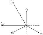
图3示出了本发明实施例提供的一种智能电能表的错接线检测方法中三相三线智能电能表的电压相量图;FIG. 3 shows a voltage phasor diagram of a three-phase three-wire smart energy meter in a method for detecting wrong wiring of a smart energy meter provided by an embodiment of the present invention;
图4示出了本发明实施例提供的一种智能电能表的错接线检测方法中三相三线智能电能表的相量图谱;4 shows a phasor diagram of a three-phase three-wire smart electric energy meter in a method for detecting wrong wiring of a smart electric energy meter provided by an embodiment of the present invention;
图5示出了本发明实施例提供的一种智能电能表的错接线检测方法中三相三线智能电能表的相量图谱中每一元件的电压接线方式和电流接线方式。FIG. 5 shows the voltage wiring mode and the current wiring mode of each element in the phasor diagram of the three-phase three-wire smart energy meter in a method for detecting miswiring of a smart energy meter provided by an embodiment of the present invention.
具体实施方式Detailed ways
下面将参照附图更详细地描述本申请的示例性实施例。虽然附图中显示了本申请的示例性实施例,然而应当理解,可以以各种形式实现本申请而不应被这里阐述的实施例所限制。相反,提供这些实施例是为了能够更透彻地理解本申请,并且能够将本申请的范围完整的传达给本领域的技术人员。Exemplary embodiments of the present application will be described in more detail below with reference to the accompanying drawings. While exemplary embodiments of the present application are shown in the drawings, it should be understood that the present application may be embodied in various forms and should not be limited by the embodiments set forth herein. Rather, these embodiments are provided so that the application will be more thoroughly understood, and will fully convey the scope of the application to those skilled in the art.
本申请实施例提供了一种智能电能表的错接线检测方法,如图1所示,该方法包括:The embodiment of the present application provides a method for detecting wrong wiring of a smart electric energy meter. As shown in FIG. 1 , the method includes:
101、接收智能电能表上传的运行数据,并获取智能电能表的负荷特性。101. Receive the operation data uploaded by the smart electric energy meter, and obtain the load characteristic of the smart electric energy meter.
在本申请实施例中,智能电能表的错接线检测方法可应用于贸易结算关口、贸易结算用户以及线损考核关口等任何计量点,对计量点中处于第I象限、第II象限、第III象限以及第IV象限的不同运行象限以及不同负荷特性下的智能电能表的错接线类型进行研判。In the embodiment of the present application, the method for detecting wrong wiring of smart electric energy meters can be applied to any metering points such as trade settlement gateways, trade settlement users, and line loss assessment gateways. The wrong wiring types of smart energy meters under different operation quadrants of quadrant and IV quadrant and different load characteristics are studied and judged.
具体地,智能电能表能够显示表中每一元件的电压、电流、功率因数、有功功率、无功功率,以及电压相序、总有功功率、总无功功率、总功率因数等智能电能表上传的运行数据,可实时进行读取,也可通过采集系统远程采集以上运行数据。负荷特性是根据一次负荷潮流方向,以及用电设备的投入运行情况、负荷率以及无功补偿装置投入情况等因素进行综合分析,进而确定负荷的类型,即负荷为感性负荷还是容性负荷,以及智能电能表具体的运行象限。Specifically, the smart energy meter can display the voltage, current, power factor, active power, reactive power of each element in the meter, as well as voltage phase sequence, total active power, total reactive power, total power factor, etc. The operating data can be read in real time, or the above operating data can be collected remotely through the acquisition system. The load characteristic is based on a comprehensive analysis of factors such as the direction of the primary load flow, the operation of the electrical equipment, the load rate, and the input of the reactive power compensation device, and then determines the type of the load, that is, whether the load is an inductive load or a capacitive load, and The specific operating quadrant of the smart energy meter.
102、提取运行数据中的功率数据,并判断功率数据是否在预设功率数据范围内。102. Extract power data in the operation data, and determine whether the power data is within a preset power data range.
在本申请实施例中,通过获取智能电能表运行数据中的功率数据,再根据供电线路或用电用户在不同感性和容性负荷特性下呈现出的规律和逻辑关系,判断功率数据是否满足预设的规律以及逻辑关系,以确定智能电能表是否正常运行。In the embodiment of the present application, by acquiring the power data in the operation data of the smart electric energy meter, and then according to the laws and logical relationships presented by the power supply line or electricity users under different inductive and capacitive load characteristics, it is judged whether the power data meets the predetermined requirements. Set the rules and logical relationships to determine whether the smart energy meter is running normally.
具体地,供电线路或用电用户在不同感性和容性负荷特性下呈现出的规律和逻辑关系,具体体现在通过负荷特性获取到的智能电能表在第I象限、第II象限、第III象限以及第IV象限的不同运行象限下预设的各功率数据范围,当智能电能表运行数据中的功率数据在预设功率数据范围内,则表示智能电能表运行正常。Specifically, the laws and logical relationships presented by power supply lines or electricity users under different inductive and capacitive load characteristics are embodied in the first quadrant, the second quadrant, and the third quadrant of the smart energy meter obtained through the load characteristics. and preset power data ranges in different operation quadrants of the IV quadrant. When the power data in the smart energy meter operation data is within the preset power data range, it means that the smart energy meter operates normally.
103、若功率数据不在预设功率数据范围内,则提取运行数据中的电压相序,并根据电压相序的相序类型生成电压相量图。103. If the power data is not within the preset power data range, extract the voltage phase sequence in the operation data, and generate a voltage phasor diagram according to the phase sequence type of the voltage phase sequence.
在本申请实施例中,当智能电能表的功率数据不在预设功率数据范围内,即智能电能表不满足在不同感性和容性负荷特性下应呈现出的规律和逻辑关系,因此可以确定智能电能表运行异常,存在错接线的情况,需要进一步对智能电能表的错接线类型进行判断。In the embodiment of the present application, when the power data of the smart energy meter is not within the preset power data range, that is, the smart energy meter does not meet the laws and logical relationships that should be presented under different inductive and capacitive load characteristics, so it can be determined that the smart energy The electric energy meter is running abnormally and there is a wrong wiring situation. It is necessary to further judge the wrong wiring type of the smart electric energy meter.
具体地,对智能电能表错接线的类型进行判断,需要生成相量图谱,首先根据读取到的智能电能表运行数据中电压的相关数据,生成电压相量图,并以电压相量图为基础进一步生成智能电能表的相量图谱。Specifically, it is necessary to generate a phasor map to determine the type of wrong wiring of the smart energy meter. First, generate a voltage phasor diagram according to the voltage-related data in the read operation data of the smart energy meter, and use the voltage phasor diagram as the The basis further generates the phasor map of the smart energy meter.
104、通过运行数据计算智能电能表内每一元件的电流相量,将每一元件的电流相量添加在电压相量图中,生成智能电能表的相量图谱。104. Calculate the current phasor of each element in the smart electric energy meter through the operation data, add the current phasor of each element to the voltage phasor diagram, and generate a phasor diagram of the smart electric energy meter.
在本申请实施例中,根据智能电能表运行数据中每一元件的功率因数值,通过计算反余弦函数得出每一元件的相位角,再结合每一元件的有功功率和无功功率的方向,确定每一元件的电流相量,最后将电流相量添加在电压相量图中,得到智能电能表的相量图谱。In the embodiment of the present application, according to the power factor value of each element in the operating data of the smart energy meter, the phase angle of each element is obtained by calculating the inverse cosine function, and then the direction of the active power and reactive power of each element is combined. , determine the current phasor of each element, and finally add the current phasor to the voltage phasor diagram to obtain the phasor diagram of the smart energy meter.
105、利用负荷特性确定相量图谱中每一元件的电压接入方式和每一元件的电流接入方式,并根据每一元件的电压接入方式和每一元件的电流接入方式,得到智能电能表的错接线类型。105. Use the load characteristics to determine the voltage access mode of each element and the current access mode of each element in the phasor diagram, and obtain intelligent Wrong wiring type of energy meter.
在本申请实施例中,在生成的智能电能表的相量图谱中,根据负荷特性,能够确定每一元件的电压接入方式和每一元件的电流接入方式,进而对智能电能表错误接线的类型进行准确研判,不需要进行人工测试,可使研判准确率达到100%。In the embodiment of the present application, in the generated phasor map of the smart energy meter, according to the load characteristics, the voltage connection mode of each element and the current connection mode of each element can be determined, and then the smart energy meter is incorrectly wired The type of the device can be accurately researched and judged without manual testing, which can make the research and judgment accuracy rate reach 100%.
本发明提供的一种智能电能表的错接线检测方法、装置、存储介质及设备,首先接收智能电能表上传的运行数据,并获取智能电能表的负荷特性,其次提取运行数据中的功率数据,并判断功率数据是否在预设功率数据范围内,若功率数据不在预设功率数据范围内,则提取运行数据中的电压相序,并根据电压相序的相序类型生成电压相量图,进而通过运行数据计算智能电能表内每一元件的电流相量,将每一元件的电流相量添加在电压相量图中,生成智能电能表的相量图谱,最后利用负荷特性确定相量图谱中每一元件的电压接入方式和每一元件的电流接入方式,并根据每一元件的电压接入方式和每一元件的电流接入方式,得到智能电能表的错接线类型。上述方法通过对智能电能表运行数据中的功率数据的逻辑关系进行判断,并利用运行数据确定相量图谱,再根据智能电能表的负荷特性分析智能电能表的错接线类型,实现对智能电能表的错接线类型进行自动化判别,提升了判别结果的准确度,同时避免了作业的安全风险。The invention provides a method, device, storage medium and equipment for detecting wrong wiring of a smart electric energy meter. First, the operation data uploaded by the intelligent electric energy meter is received, and the load characteristic of the intelligent electric energy meter is obtained, and then the power data in the operation data is extracted. And determine whether the power data is within the preset power data range, if the power data is not within the preset power data range, extract the voltage phase sequence in the operating data, and generate a voltage phasor diagram according to the phase sequence type of the voltage phase sequence, and then Calculate the current phasor of each element in the smart energy meter through the operating data, add the current phasor of each element to the voltage phasor diagram, generate the phasor diagram of the smart energy meter, and finally use the load characteristics to determine the phasor diagram in the phasor diagram The voltage connection method of each element and the current connection method of each element are obtained, and the wrong wiring type of the smart energy meter is obtained according to the voltage connection method of each element and the current connection method of each element. The above method judges the logical relationship of the power data in the operation data of the smart electric energy meter, determines the phasor diagram by using the operation data, and then analyzes the wrong wiring type of the intelligent electric energy meter according to the load characteristics of the intelligent electric energy meter, so as to realize the intelligent electric energy meter. The type of wrong wiring is automatically judged, which improves the accuracy of the judgment result and avoids the safety risk of the operation.
在一个实施例中,步骤103具体可以通过以下方法实现:当电压相序的相序类型为正相序时,沿顺时针间隔120°依次添加智能电能表的各相电压,提取运行数据中每一元件的电压相量,并根据智能电能表的接线方式,添加每一元件的电压相量,得到电压相量图,而当电压相序的相序类型为逆相序时,沿逆时针间隔120°依次添加智能电能表的各相电压,提取运行数据中每一元件的电压相量,并根据智能电能表的接线方式,添加每一元件的电压相量,得到电压相量图。In one embodiment, step 103 can be specifically implemented by the following method: when the phase sequence type of the voltage phase sequence is a positive phase sequence, sequentially adding the voltages of each phase of the smart energy meter at 120° clockwise intervals, and extracting each phase voltage in the operating data. The voltage phasor of one element, and according to the wiring method of the smart energy meter, add the voltage phasor of each element to obtain the voltage phasor diagram, and when the phase sequence type of the voltage phase sequence is reverse phase sequence, the interval is counterclockwise. Add the voltage of each phase of the smart energy meter in sequence by 120°, extract the voltage phasor of each element in the operating data, and add the voltage phasor of each element according to the wiring method of the smart energy meter to obtain a voltage phasor diagram.
在本实施例中,智能电能表的电压相序类型分为正相序和逆相序,根据不同的相序类型以及测得的每一元件的电压相量,生成正确的电压相量图。In this embodiment, the voltage phase sequence types of the smart energy meter are divided into positive phase sequence and reverse phase sequence. According to different phase sequence types and the measured voltage phasor of each element, a correct voltage phasor diagram is generated.
具体地,本申请实施例提供的一种智能电能表的错接线检测方法,选用接线方式为三相三线的智能电能表,其电压规格为3*100V,电流规格为3*1.5(6)A,测得其运行数据如表1所示。Specifically, a method for detecting wrong wiring of a smart electric energy meter provided in the embodiment of the present application selects a smart electric energy meter whose wiring mode is three-phase and three-wire, and whose voltage specification is 3*100V and current specification is 3*1.5(6)A , the measured operating data are shown in Table 1.


表1Table 1
由于测得三相三线智能电能表的电压相序为正相序,以及测得每一元件的电压值,可知根据电压相量确定正相序的电压相量图如图3所示。Since the measured voltage phase sequence of the three-phase three-wire smart energy meter is a positive phase sequence, and the voltage value of each element is measured, it can be seen that the voltage phasor diagram for determining the positive phase sequence according to the voltage phasor is shown in Figure 3.
在一个实施例中,步骤104具体可以通过以下方法实现:首先通过每一元件的功率因数,计算每一元件的相位角数值,其次根据每一元件的有功功率和无功功率,确定每一元件的相位角方向,再根据每一元件的相位角数值和相位角方向,计算每一元件的电压相量与电流相量之间的位置关系和角度,进而根据每一元件的电压相量与电流相量之间的位置关系和角度以及每一元件的电流值,得到每一元件的电流相量,最后将每一元件的电流相量添加在电压相量图中,生成智能电能表的相量图谱。In one embodiment, step 104 can be specifically implemented by the following method: firstly, calculating the phase angle value of each element according to the power factor of each element, and secondly, determining each element according to the active power and reactive power of each element According to the phase angle value and phase angle direction of each element, the positional relationship and angle between the voltage phasor and the current phasor of each element are calculated, and then according to the voltage phasor and current phasor of each element The positional relationship and angle between the phasors and the current value of each element, the current phasor of each element is obtained, and finally the current phasor of each element is added to the voltage phasor diagram to generate the phasor of the smart energy meter Atlas.
在本实施例中,以上述实施例中获取到的三相三线的智能电能表的运行数据以及生成的电压相量图为基准,计算其中第一元件的电流相量


在一个实施例中,步骤105具体可以通过以下方法实现:根据智能电能表的负荷特性,得到每一元件的电流相量与智能电能表的相电压之间的理论位置关系和角度,再根据理论位置关系和角度,得到相量图谱中智能电能表的相电压的相别和每一元件的电流相量的相别,进而根据相量图谱中智能电能表的相电压的相别和每一元件的电流相量的相别,确定每一元件的电压接线方式和每一元件的电流接线方式。In one embodiment, step 105 can be specifically implemented by the following method: obtaining the theoretical positional relationship and angle between the current phasor of each element and the phase voltage of the smart energy meter according to the load characteristics of the smart energy meter, and then according to the theoretical position relationship and angle, obtain the phase difference of the phase voltage of the smart energy meter in the phasor map and the phase difference of the current phasor of each element, and then according to the phase difference of the phase voltage of the smart energy meter in the phasor map and the phase difference of each element The phase difference of the current phasors determines the voltage connection mode of each element and the current connection mode of each element.
在本实施例中,以上述实施例中获取到的三相三线的智能电能表的运行数据以及生成的相量图谱为基准,由于


在一个实施例中,步骤105具体可以通过以下方法实现:首先获取智能电能表内每一元件预设的电压接线方式和每一元件预设的电流接线方式,再将每一元件的电压接线方式与每一元件预设的电压接线方式进行比对,并将每一元件的电流接线方式与每一元件预设的电流接线方式进行比对,得到每一元件的电压接线方式的比对结果和每一元件的电流接线方式比对结果,最后根据每一元件的电压接线方式的比对结果,和/或每一元件的电流接线方式比对结果,确定智能电能表的错接线类型,其中,错接线类型包括电压错接、电流错接、电压互感器极性反接和电流互感器极性反接。In one embodiment, step 105 can be specifically implemented by the following method: firstly obtain the preset voltage connection mode of each element and the preset current connection mode of each element in the smart energy meter, and then connect the voltage connection mode of each element Compare with the preset voltage connection mode of each element, and compare the current connection mode of each element with the preset current connection mode of each element, and obtain the comparison result of the voltage connection mode of each element and The comparison result of the current wiring mode of each element, and finally according to the comparison result of the voltage wiring mode of each element, and/or the comparison result of the current wiring mode of each element, determine the wrong wiring type of the smart energy meter, wherein, Misconnection types include voltage misconnection, current misconnection, reversed voltage transformer polarity, and reversed current transformer polarity.
在本实施例中,智能电能表在不同的接线方式下,其电压电流具有统一正确的接线方式。具体地,对于三相三线智能电能表,其正确接线为电压接线情况为相电压


在一个实施例中,步骤102具体可以通过以下方法实现:根据智能电能表的负荷特性,获取预设功率数据范围,其中,预设功率数据范围包括智能电能表在第I象限、第II象限、第III象限以及第IV象限的不同运行象限和不同负载功率因数角下所对应的总功率因数变化范围和每一元件的功率因数变化范围,再判断总功率因数是否在总功率因数变化范围内,并判断每一元件的功率因数是否在对应的每一元件的功率因数变化范围内,若总功率因数不在总功率因数的变化范围内,和/或每一元件的功率因数不在对应的每一元件的功率因数变化范围内,则判定功率数据不在预设功率数据范围内。In one embodiment, step 102 can be specifically implemented by the following method: obtaining a preset power data range according to the load characteristics of the smart electric energy meter, wherein the preset power data range includes the smart electric energy meter in the first quadrant, the second quadrant, The total power factor variation range and the power factor variation range of each component corresponding to the different operating quadrants and different load power factor angles of the third and fourth quadrants, and then determine whether the total power factor is within the total power factor variation range, And judge whether the power factor of each element is within the variation range of the corresponding power factor of each element, if the total power factor is not within the variation range of the total power factor, and/or the power factor of each element is not within the corresponding power factor of each element Within the range of power factor variation, it is determined that the power data is not within the preset power data range.
在本实施例中,智能电能表的预设功率数据范围具体是指智能电能表的功率因数绝对值按照0.866~1定义为“大”,0.5~0.866定义为“中”,0~0.5定义为“小”,在三相三线智能电能表各元件电压接近于额定值,三相四线智能电能表各元件电压接近于额定值,且各元件电流有一定幅值,幅值一般需在0.075A及以上,呈现出的特性和规律,例如:当智能电能表为三相三线智能电能表时,智能电能表在Ⅰ象限感性负荷下,智能电能表的负载功率因数角为0°~30°的情况下,智能电能表的总功率因数变化范围为0.866~1,绝对值为“大”,其中第一元件的功率因数变化范围为0.5~0.866,绝对值为“中”,第二元件功率因数变化范围为0.866~1,绝对值为“大”;智能电能表在Ⅱ象限容性负荷下,智能电能表的负载功率因数角为0°~30°的情况下,智能电能表的总功率因数变化范围为-0.866~-1,绝对值为“大”,其中第一元件功率因数变化范围为-0.866~-1,绝对值为“大”,第二元件功率因数变化范围为-0.5~-0.866,绝对值为“中”;智能电能表在Ⅲ象限感性负荷下,智能电能表的负载功率因数角为30°~60°的情况下,总功率因数变化范围为-0.5~-0.866,绝对值为“中”,其中第一元件功率因数变化范围为0~-0.5,绝对值为“小”,其中第二元件功率因数变化范围为-0.866~-1,绝对值为“大”;智能电能表在Ⅳ象限容性负荷下,智能电能表的负载功率因数角为60°~90°的情况下,总功率因数变化范围为0~0.5,绝对值为“小”,其中第一元件功率因数变化范围为0.5~0.866,绝对值为“中”,其中第二元件功率因数变化范围为0~-0.5,绝对值为“小”。In this embodiment, the preset power data range of the smart energy meter specifically refers to that the absolute value of the power factor of the smart energy meter is defined as "large" according to 0.866-1, 0.5-0.866 is defined as "medium", and 0-0.5 is defined as "Small", the voltage of each component of the three-phase three-wire smart energy meter is close to the rated value, the voltage of each component of the three-phase four-wire smart energy meter is close to the rated value, and the current of each component has a certain amplitude, and the amplitude generally needs to be 0.075A and above, showing the characteristics and laws, for example: when the smart energy meter is a three-phase three-wire smart energy meter, the smart energy meter is under the inductive load of the I quadrant, and the load power factor angle of the smart energy meter is 0° ~ 30° In this case, the variation range of the total power factor of the smart energy meter is 0.866 to 1, and the absolute value is "large". The variation range is 0.866 to 1, and the absolute value is "large"; when the smart energy meter is under the capacitive load of the II quadrant, and the load power factor angle of the smart energy meter is 0° to 30°, the total power factor of the smart energy meter The variation range is -0.866~-1, the absolute value is "large", the variation range of the power factor of the first element is -0.866~-1, the absolute value is "large", and the variation range of the power factor of the second element is -0.5~- 0.866, the absolute value is "medium"; when the smart energy meter is in the III quadrant inductive load, and the load power factor angle of the smart energy meter is 30°~60°, the total power factor variation range is -0.5~-0.866, absolute The value is "Medium", in which the power factor of the first element varies in the range of 0 to -0.5, and the absolute value is "Small", and the variation in the power factor of the second element is in the range of -0.866 to -1, and the absolute value is "Large"; intelligent When the electric energy meter is under the capacitive load of the IV quadrant and the load power factor angle of the smart electric energy meter is 60°~90°, the total power factor variation range is 0~0.5, and the absolute value is "small". The variation range of the factor is 0.5~0.866, and the absolute value is "medium", and the variation range of the power factor of the second element is 0~-0.5, and the absolute value is "small".
当智能电能表为三相四线智能电能表时,智能电能表在Ⅰ象限感性负荷下,负载功率因数角0°~30°的情况下,总功率因数、第一元件功率因数、第二元件功率因数、第三元件功率因数变化范围为0.866~1,绝对值为“大”;智能电能表在Ⅱ象限容性负荷下,负载功率因数角为30°~60°的情况下,总功率因数、第一元件功率因数、第二元件功率因数、第三元件功率因数变化范围为-0.5~-0.866,绝对值为“中”;智能电能表在Ⅲ象限感性负荷下,负载功率因数角为30°~60°的情况下,总功率因数、第一元件功率因数、第二元件功率因数、第三元件功率因数变化范围为-0.5~-0.866,绝对值为“中”;智能电能表在Ⅳ象限容性负荷下,负载功率因数角为60°~90°的情况下,总功率因数、第一元件功率因数、第二元件功率因数、第三元件功率因数变化范围为0~0.5,绝对值为“小”;When the smart energy meter is a three-phase four-wire smart energy meter, the total power factor, the power factor of the first element, the power factor of the second element, and the The power factor and the power factor of the third element change in the range of 0.866 to 1, and the absolute value is "large"; when the smart energy meter is under the capacitive load of the II quadrant and the load power factor angle is 30° to 60°, the total power factor , The power factor of the first element, the power factor of the second element, and the power factor of the third element vary from -0.5 to -0.866, and the absolute value is "medium"; under the inductive load of the third quadrant, the load power factor angle of the smart energy meter is 30 In the case of °~60°, the variation range of the total power factor, the power factor of the first element, the power factor of the second element, and the power factor of the third element is -0.5~-0.866, and the absolute value is "medium"; Under the quadrant capacitive load, when the load power factor angle is 60°~90°, the variation range of the total power factor, the power factor of the first element, the power factor of the second element, and the power factor of the third element is 0~0.5, the absolute value for "small";
在以上三相三线智能电能表以及三相四线智能电能表中,只要存在智能电能表的总功率因数不在总功率因数的变化范围内,和/或每一元件的功率因数不在对应的每一元件的功率因数变化范围内的情况出现,则可判定功率数据不在预设功率数据范围内。In the above three-phase three-wire smart energy meters and three-phase four-wire smart energy meters, as long as the total power factor of the smart energy meter is not within the variation range of the total power factor, and/or the power factor of each element is not within the corresponding If the situation occurs within the variation range of the power factor of the element, it can be determined that the power data is not within the preset power data range.
在一个实施例中,步骤102还可以通过以下方法实现:若总功率因数在总功率因数的变化范围内,且每一元件的功率因数在对应的每一元件的功率因数变化范围内,则计算每一元件的功率因数的和值,并计算和值与总功率因数的比值,将比值与预设比值进行比对,其中,当智能电能表的接线方式为三相三线时,预设比值为
在本实施例中,当智能电能表的总功率因数在总功率因数的变化范围内,且智能电能表中的每一元件的功率因数在对应的每一元件的功率因数变化范围内,并不能完全说明智能电能表的接线是完全正确的,还需根据功率因数之间的逻辑关系对智能电能表的接线情况做进一步的判断。In this embodiment, when the total power factor of the smart energy meter is within the variation range of the total power factor, and the power factor of each element in the smart energy meter is within the corresponding power factor variation range of each element, it cannot be It fully shows that the wiring of the smart energy meter is completely correct, and it is necessary to further judge the wiring of the smart energy meter according to the logical relationship between the power factors.
具体地,通过计算功率因数之间的逻辑关系,也就是通过将智能电能表中的每一元件的功率因数相加得到和值,再计算和值与总功率因数的比值。进一步地,将比值与预设比值进行比对,其中,当智能电能表的接线方式为三相三线时,预设比值为
公式1:
其中

具体计算三相四线智能电能表的总功率因数与每一元件之间的逻辑关系可以通过下述公式2实现:The specific calculation of the logical relationship between the total power factor of the three-phase four-wire smart energy meter and each element can be realized by the following formula 2:
公式2:
其中

进一步的,作为图1所示方法的具体实现,本实施例提供了智能电能表的错接线检测装置,如图2所示,该装置包括:获取模块21、判断模块22、提取模块23、计算模块24和输出模块25,其中:Further, as a specific implementation of the method shown in FIG. 1 , the present embodiment provides a device for detecting wrong wiring of a smart electric energy meter. As shown in FIG. 2 , the device includes: an
获取模块21,可用于接收智能电能表上传的运行数据,并获取智能电能表的负荷特性;The
判断模块22,可用于提取运行数据中的功率数据,并判断功率数据是否在预设功率数据范围内;The
提取模块23,可用于若功率数据不在预设功率数据范围内,则提取运行数据中的电压相序,并根据电压相序的相序类型生成电压相量图;The
计算模块24,可用于通过运行数据计算智能电能表内每一元件的电流相量,将每一元件的电流相量添加在电压相量图中,生成智能电能表的相量图谱;The
输出模块25,可用于利用负荷特性确定相量图谱中每一元件的电压接入方式和每一元件的电流接入方式,并根据每一元件的电压接入方式和每一元件的电流接入方式,得到智能电能表的错接线类型。The
在具体的应用场景中,提取模块23具体包括当电压相序的相序类型为正相序时,沿顺时针间隔120°依次添加智能电能表的各相电压,提取运行数据中每一元件的电压相量,并根据智能电能表的接线方式,添加每一元件的电压相量,得到电压相量图;当电压相序的相序类型为逆相序时,沿逆时针间隔120°依次添加智能电能表的各相电压,提取运行数据中每一元件的电压相量,并根据智能电能表的接线方式,添加每一元件的电压相量,得到电压相量图。In a specific application scenario, the
在具体的应用场景中,计算模块24具体可用于通过每一元件的功率因数,计算每一元件的相位角数值;根据每一元件的有功功率和无功功率,确定每一元件的相位角方向;根据每一元件的相位角数值和相位角方向,计算每一元件的电压相量与电流相量之间的位置关系和角度;根据每一元件的电压相量与电流相量之间的位置关系和角度以及每一元件的电流值,得到每一元件的电流相量;将每一元件的电流相量添加在电压相量图中,生成智能电能表的相量图谱。In a specific application scenario, the
在具体的应用场景中,输出模块25具体可用于根据智能电能表的负荷特性,得到每一元件的电流相量与智能电能表的相电压之间的理论位置关系和角度;根据理论位置关系和角度,得到相量图谱中智能电能表的相电压的相别和每一元件的电流相量的相别;根据相量图谱中智能电能表的相电压的相别和每一元件的电流相量的相别,确定每一元件的电压接线方式和每一元件的电流接线方式。In a specific application scenario, the
在具体的应用场景中,输出模块25具体可用于获取智能电能表内每一元件预设的电压接线方式和每一元件预设的电流接线方式;将每一元件的电压接线方式与每一元件预设的电压接线方式进行比对,并将每一元件的电流接线方式与每一元件预设的电流接线方式进行比对,得到每一元件的电压接线方式的比对结果和每一元件的电流接线方式比对结果;根据每一元件的电压接线方式的比对结果,和/或每一元件的电流接线方式比对结果,确定智能电能表的错接线类型,其中,错接线类型包括电压错接、电流错接、电压互感器极性反接和电流互感器极性反接。In a specific application scenario, the
在具体的应用场景中,判断模块22具体可用于根据智能电能表的负荷特性,获取预设功率数据范围,其中,预设功率数据范围包括智能电能表在第I象限、第II象限、第III象限以及第IV象限的不同运行象限和不同负载功率因数角下所对应的总功率因数变化范围和每一元件的功率因数变化范围;判断总功率因数是否在总功率因数变化范围内,并判断每一元件的功率因数是否在对应的每一元件的功率因数变化范围内;若总功率因数不在总功率因数的变化范围内,和/或每一元件的功率因数不在对应的每一元件的功率因数变化范围内,则判定功率数据不在预设功率数据范围内。In a specific application scenario, the judging
在具体的应用场景中,判断模块22还可用于若总功率因数在总功率因数的变化范围内,且每一元件的功率因数在对应的每一元件的功率因数变化范围内,则计算每一元件的功率因数的和值,并计算和值与总功率因数的比值,将比值与预设比值进行比对,其中,当智能电能表的接线方式为三相三线时,预设比值为
需要说明的是,本实施例提供的一种智能电能表的错接线检测装置所涉及各功能单元的其它相应描述,可以参考图1中的对应描述,在此不再赘述。It should be noted that, for other corresponding descriptions of the functional units involved in the device for detecting miswiring of a smart electric energy meter provided in this embodiment, reference may be made to the corresponding descriptions in FIG. 1 , which will not be repeated here.
基于上述如图1所示方法,相应的,本实施例还提供了一种存储介质,其上存储有计算机程序,该程序被处理器执行时实现上述如图1所示的智能电能表的错接线检测方法。Based on the above method shown in FIG. 1 , correspondingly, the present embodiment also provides a storage medium on which a computer program is stored, and when the program is executed by a processor, the above error of the smart energy meter shown in FIG. 1 is realized. Wiring detection method.
基于这样的理解,本申请的技术方案可以以软件产品的形式体现出来,该待识别软件产品可以存储在一个非易失性存储介质(可以是CD-ROM,U盘,移动硬盘等)中,包括若干指令用以使得一台计算机设备(可以是个人计算机,服务器,或者网络设备等)执行本申请各个实施场景的方法。Based on this understanding, the technical solution of the present application can be embodied in the form of a software product, and the software product to be identified can be stored in a non-volatile storage medium (which can be a CD-ROM, U disk, mobile hard disk, etc.), Several instructions are included to cause a computer device (which may be a personal computer, a server, or a network device, etc.) to execute the methods of various implementation scenarios of the present application.
基于上述如图1所示的方法,以及图2所示的智能电能表的错接线检测装置实施例,为了实现上述目的,本实施例还提供了一种智能电能表的错接线检测的实体设备,具体可以为个人计算机、服务器、智能手机、平板电脑、智能手表、或者其它网络设备等,该实体设备包括存储介质和处理器;存储介质,用于存储计算机程序;处理器,用于执行计算机程序以实现上述如图1所示的方法。Based on the above method shown in FIG. 1 and the embodiment of the device for detecting wrong wiring of a smart energy meter shown in FIG. 2 , in order to achieve the above purpose, this embodiment also provides a physical device for detecting wrong wiring of a smart energy meter , specifically a personal computer, a server, a smart phone, a tablet computer, a smart watch, or other network devices, etc., the physical device includes a storage medium and a processor; a storage medium for storing computer programs; a processor for executing the computer program to achieve the above-mentioned method shown in Figure 1.
可选的,该实体设备还可以包括用户接口、网络接口、摄像头、射频(RadioFrequency,RF)电路,传感器、音频电路、WI-FI模块等等。用户接口可以包括显示屏(Display)、输入单元比如键盘(Keyboard)等,可选用户接口还可以包括USB接口、读卡器接口等。网络接口可选的可以包括标准的有线接口、无线接口(如WI-FI接口)等。Optionally, the physical device may further include a user interface, a network interface, a camera, a radio frequency (Radio Frequency, RF) circuit, a sensor, an audio circuit, a WI-FI module, and the like. The user interface may include a display screen (Display), an input unit such as a keyboard (Keyboard), etc., and the optional user interface may also include a USB interface, a card reader interface, and the like. Optional network interfaces may include standard wired interfaces, wireless interfaces (such as WI-FI interfaces), and the like.
本领域技术人员可以理解,本实施例提供的智能电能表的错接线检测的实体设备结构并不构成对该实体设备的限定,可以包括更多或更少的部件,或者组合某些部件,或者不同的部件布置。Those skilled in the art can understand that the physical device structure of the miswiring detection of the smart energy meter provided in this embodiment does not constitute a limitation on the physical device, and may include more or less components, or combine certain components, or Different component arrangements.
存储介质中还可以包括操作系统、网络通信模块。操作系统是管理上述实体设备硬件和待识别软件资源的程序,支持信息处理程序以及其它待识别软件和/或程序的运行。网络通信模块用于实现存储介质内部各组件之间的通信,以及与信息处理实体设备中其它硬件和软件之间通信。The storage medium may also include an operating system and a network communication module. The operating system is a program that manages the above-mentioned physical device hardware and software resources to be identified, and supports the operation of information processing programs and other software and/or programs to be identified. The network communication module is used to realize the communication between various components in the storage medium, as well as the communication with other hardware and software in the information processing entity device.
通过以上的实施方式的描述,本领域的技术人员可以清楚地了解到本申请可以借助软件加必要的通用硬件平台的方式来实现,也可以通过硬件实现。通过应用本申请的技术方案,首先接收智能电能表上传的运行数据,并获取智能电能表的负荷特性,其次提取运行数据中的功率数据,并判断功率数据是否在预设功率数据范围内,若功率数据不在预设功率数据范围内,则提取运行数据中的电压相序,并根据电压相序的相序类型生成电压相量图,进而通过运行数据计算智能电能表内每一元件的电流相量,将每一元件的电流相量添加在电压相量图中,生成智能电能表的相量图谱,最后利用负荷特性确定相量图谱中每一元件的电压接入方式和每一元件的电流接入方式,并根据每一元件的电压接入方式和每一元件的电流接入方式,得到智能电能表的错接线类型。上述方法通过对智能电能表运行数据中的功率数据的逻辑关系进行判断,并利用运行数据确定相量图谱,再根据智能电能表的负荷特性分析智能电能表的错接线类型,实现对智能电能表的错接线类型进行自动化判别,提升了判别结果的准确度,同时避免了作业的安全风险。From the description of the above embodiments, those skilled in the art can clearly understand that the present application can be implemented by means of software plus a necessary general hardware platform, and can also be implemented by hardware. By applying the technical solution of the present application, firstly, the operation data uploaded by the smart energy meter is received, and the load characteristics of the smart energy meter are obtained, and then the power data in the operation data is extracted, and it is judged whether the power data is within the preset power data range. If the power data is not within the preset power data range, the voltage phase sequence in the operation data is extracted, and the voltage phasor diagram is generated according to the phase sequence type of the voltage phase sequence, and then the current phase sequence of each element in the smart energy meter is calculated through the operation data. Add the current phasor of each element to the voltage phasor diagram to generate the phasor diagram of the smart energy meter, and finally use the load characteristics to determine the voltage access mode of each element and the current of each element in the phasor diagram The connection method is determined, and the wrong wiring type of the smart energy meter is obtained according to the voltage connection method of each element and the current connection method of each element. The above method judges the logical relationship of the power data in the operation data of the smart electric energy meter, determines the phasor diagram by using the operation data, and then analyzes the wrong wiring type of the intelligent electric energy meter according to the load characteristics of the intelligent electric energy meter, so as to realize the intelligent electric energy meter. The type of wrong wiring is automatically judged, which improves the accuracy of the judgment result and avoids the safety risk of the operation.
本领域技术人员可以理解附图只是一个优选实施场景的示意图,附图中的模块或流程并不一定是实施本申请所必须的。本领域技术人员可以理解实施场景中的装置中的模块可以按照实施场景描述进行分布于实施场景的装置中,也可以进行相应变化位于不同于本实施场景的一个或多个装置中。上述实施场景的模块可以合并为一个模块,也可以进一步拆分成多个子模块。Those skilled in the art can understand that the accompanying drawing is only a schematic diagram of a preferred implementation scenario, and the modules or processes in the accompanying drawing are not necessarily necessary to implement the present application. Those skilled in the art can understand that the modules in the device in the implementation scenario may be distributed in the device in the implementation scenario according to the description of the implementation scenario, or may be located in one or more devices different from the implementation scenario with corresponding changes. The modules of the above implementation scenarios may be combined into one module, or may be further split into multiple sub-modules.
上述本申请序号仅仅为了描述,不代表实施场景的优劣。以上公开的仅为本申请的几个具体实施场景,但是,本申请并非局限于此,任何本领域的技术人员能思之的变化都应落入本申请的保护范围。The above serial numbers in the present application are only for description, and do not represent the pros and cons of the implementation scenarios. The above disclosures are only a few specific implementation scenarios of the present application, however, the present application is not limited thereto, and any changes that can be conceived by those skilled in the art should fall within the protection scope of the present application.
Claims (10)
Translated fromChinese
Priority Applications (1)
| Application Number | Priority Date | Filing Date | Title |
|---|---|---|---|
| CN202210601005.4ACN114879121A (en) | 2022-05-30 | 2022-05-30 | Method, device, storage medium and device for detecting wrong wiring of smart electric energy meter |
Applications Claiming Priority (1)
| Application Number | Priority Date | Filing Date | Title |
|---|---|---|---|
| CN202210601005.4ACN114879121A (en) | 2022-05-30 | 2022-05-30 | Method, device, storage medium and device for detecting wrong wiring of smart electric energy meter |
Publications (1)
| Publication Number | Publication Date |
|---|---|
| CN114879121Atrue CN114879121A (en) | 2022-08-09 |
Family
ID=82680612
Family Applications (1)
| Application Number | Title | Priority Date | Filing Date |
|---|---|---|---|
| CN202210601005.4APendingCN114879121A (en) | 2022-05-30 | 2022-05-30 | Method, device, storage medium and device for detecting wrong wiring of smart electric energy meter |
Country Status (1)
| Country | Link |
|---|---|
| CN (1) | CN114879121A (en) |
Cited By (4)
| Publication number | Priority date | Publication date | Assignee | Title |
|---|---|---|---|---|
| CN115343530A (en)* | 2022-08-15 | 2022-11-15 | 广东电网有限责任公司 | A three-phase electric energy meter |
| CN115372887A (en)* | 2022-08-29 | 2022-11-22 | 国网重庆市电力公司营销服务中心 | Quadrant abnormality detection method, device and equipment for three-phase three-wire smart energy meter |
| CN115372695A (en)* | 2022-08-29 | 2022-11-22 | 国网重庆市电力公司营销服务中心 | Anti-stealing identification method, device, storage medium and equipment for smart energy meters |
| CN115372886A (en)* | 2022-08-29 | 2022-11-22 | 国网重庆市电力公司营销服务中心 | Quadrant abnormality detection method, device and equipment for three-phase four-wire smart energy meter |
Citations (3)
| Publication number | Priority date | Publication date | Assignee | Title |
|---|---|---|---|---|
| CN110806552A (en)* | 2019-11-22 | 2020-02-18 | 国网北京市电力公司 | Wrong wiring type detection method for three-phase three-wire metering device |
| CN111983521A (en)* | 2020-06-05 | 2020-11-24 | 安徽南瑞中天电力电子有限公司 | An electric energy meter with functions of automatic identification of wrong wiring and correct measurement and method thereof |
| CN114167129A (en)* | 2021-12-06 | 2022-03-11 | 国网重庆市电力公司营销服务中心 | Method for rapidly judging wrong wiring of metering device |
- 2022
- 2022-05-30CNCN202210601005.4Apatent/CN114879121A/enactivePending
Patent Citations (3)
| Publication number | Priority date | Publication date | Assignee | Title |
|---|---|---|---|---|
| CN110806552A (en)* | 2019-11-22 | 2020-02-18 | 国网北京市电力公司 | Wrong wiring type detection method for three-phase three-wire metering device |
| CN111983521A (en)* | 2020-06-05 | 2020-11-24 | 安徽南瑞中天电力电子有限公司 | An electric energy meter with functions of automatic identification of wrong wiring and correct measurement and method thereof |
| CN114167129A (en)* | 2021-12-06 | 2022-03-11 | 国网重庆市电力公司营销服务中心 | Method for rapidly judging wrong wiring of metering device |
Non-Patent Citations (2)
| Title |
|---|
| 井斌: "电能计量装置错误接线检查方法的探讨", 《工业计量》, vol. 22, no. 2, 31 December 2012 (2012-12-31), pages 69 - 70* |
| 刘超男 等: "三相三线电能表TV 二次接地点失去时的错接线分析", 《国网技术学院学报》, vol. 22, no. 3, 29 August 2019 (2019-08-29), pages 19 - 21* |
Cited By (4)
| Publication number | Priority date | Publication date | Assignee | Title |
|---|---|---|---|---|
| CN115343530A (en)* | 2022-08-15 | 2022-11-15 | 广东电网有限责任公司 | A three-phase electric energy meter |
| CN115372887A (en)* | 2022-08-29 | 2022-11-22 | 国网重庆市电力公司营销服务中心 | Quadrant abnormality detection method, device and equipment for three-phase three-wire smart energy meter |
| CN115372695A (en)* | 2022-08-29 | 2022-11-22 | 国网重庆市电力公司营销服务中心 | Anti-stealing identification method, device, storage medium and equipment for smart energy meters |
| CN115372886A (en)* | 2022-08-29 | 2022-11-22 | 国网重庆市电力公司营销服务中心 | Quadrant abnormality detection method, device and equipment for three-phase four-wire smart energy meter |
Similar Documents
| Publication | Publication Date | Title |
|---|---|---|
| CN114879121A (en) | Method, device, storage medium and device for detecting wrong wiring of smart electric energy meter | |
| CN108445438B (en) | Method and device for detecting wrong wiring of electric energy metering device | |
| CN114879122A (en) | Method, device and equipment for detecting abnormal operation of three-phase three-wire intelligent electric energy meter | |
| WO2021109517A1 (en) | Method for detecting reliability of results of load identification device | |
| CN103513223A (en) | Electric energy meter communication interface load capacity test system | |
| CN111983548A (en) | Power factor analysis-based electric energy meter abnormity judgment device and method | |
| CN114167108A (en) | Electric energy meter phasor diagram drawing method, system, device and storage medium | |
| US8589099B2 (en) | Determining components of an electric service using tolerance ranges | |
| CN109541520B (en) | Phase-split calculation method for fault and error power of electric energy metering device | |
| CN113253155A (en) | Load testing device and method for autotransformer | |
| CN111721988A (en) | Measuring instrument and method for electric quantity compensation of metering device | |
| CN115656910A (en) | Remote calibration system, method and equipment for mutual inductor calibration instrument | |
| CN112068067A (en) | On-load error detection system of epitope isolation transformer of assembly line metrological verification device | |
| CN115308672A (en) | Electric energy metering device fault analysis method based on VV wiring traction transformer | |
| CN115236554A (en) | Method, device and computer equipment for detecting reverse polarity of voltage transformer | |
| CN119126002A (en) | A rapid screening method for incorrect wiring of three-phase four-wire electric energy meters | |
| CN104635088A (en) | Intelligent sensing device of zinc oxide arrester tester | |
| CN114879123A (en) | Method and device for detecting error wiring of three-phase four-wire intelligent electric energy meter | |
| CN109975607A (en) | Power distribution station capacity recognition methods, device, storage medium and electronic equipment | |
| CN106526305B (en) | A phasor analyzer for judging the correctness of three-phase secondary circuit wiring | |
| CN109283423A (en) | Three-phase three-wire electric energy metering device TV single-phase polarity reverse connection error wiring judgment method | |
| CN116203495A (en) | Measurement fault analysis method, device, medium and equipment based on wireless communication | |
| CN107271830B (en) | Method for rapidly calculating transformation ratio of special transformer in unbalanced state | |
| CN111781553B (en) | System and method for verifying voltage divider | |
| CN212932921U (en) | One-key type transformer hexagonal diagram rapid tester |
Legal Events
| Date | Code | Title | Description |
|---|---|---|---|
| PB01 | Publication | ||
| PB01 | Publication | ||
| SE01 | Entry into force of request for substantive examination | ||
| SE01 | Entry into force of request for substantive examination |