CN114876596A - Operation system and method for fused salt steam heat storage of cylinder cutting unit - Google Patents
Operation system and method for fused salt steam heat storage of cylinder cutting unitDownload PDFInfo
- Publication number
- CN114876596A CN114876596ACN202210542172.6ACN202210542172ACN114876596ACN 114876596 ACN114876596 ACN 114876596ACN 202210542172 ACN202210542172 ACN 202210542172ACN 114876596 ACN114876596 ACN 114876596A
- Authority
- CN
- China
- Prior art keywords
- pipeline
- molten salt
- valve
- low
- temperature molten
- Prior art date
- Legal status (The legal status is an assumption and is not a legal conclusion. Google has not performed a legal analysis and makes no representation as to the accuracy of the status listed.)
- Granted
Links
- 150000003839saltsChemical class0.000titleclaimsabstractdescription223
- 238000005338heat storageMethods0.000titleclaimsabstractdescription37
- 238000000034methodMethods0.000titleclaimsdescription15
- XLYOFNOQVPJJNP-UHFFFAOYSA-NwaterSubstancesOXLYOFNOQVPJJNP-UHFFFAOYSA-N0.000claimsdescription5
- 238000004146energy storageMethods0.000abstractdescription2
- 238000010438heat treatmentMethods0.000description29
- 238000009833condensationMethods0.000description7
- 230000008569processEffects0.000description6
- 230000008878couplingEffects0.000description3
- 238000010168coupling processMethods0.000description3
- 238000005859coupling reactionMethods0.000description3
- 230000005494condensationEffects0.000description2
- 238000001816coolingMethods0.000description2
- 238000010586diagramMethods0.000description2
- 238000000605extractionMethods0.000description2
- 230000007774longtermEffects0.000description2
- 239000000463materialSubstances0.000description2
- 238000012986modificationMethods0.000description2
- 230000004048modificationEffects0.000description2
- 238000010521absorption reactionMethods0.000description1
- QVGXLLKOCUKJST-UHFFFAOYSA-Natomic oxygenChemical compound[O]QVGXLLKOCUKJST-UHFFFAOYSA-N0.000description1
- 230000008859changeEffects0.000description1
- 230000009977dual effectEffects0.000description1
- 230000005611electricityEffects0.000description1
- 229910052760oxygenInorganic materials0.000description1
- 239000001301oxygenSubstances0.000description1
- 238000010248power generationMethods0.000description1
- 238000006467substitution reactionMethods0.000description1
Images
Classifications
- F—MECHANICAL ENGINEERING; LIGHTING; HEATING; WEAPONS; BLASTING
- F01—MACHINES OR ENGINES IN GENERAL; ENGINE PLANTS IN GENERAL; STEAM ENGINES
- F01K—STEAM ENGINE PLANTS; STEAM ACCUMULATORS; ENGINE PLANTS NOT OTHERWISE PROVIDED FOR; ENGINES USING SPECIAL WORKING FLUIDS OR CYCLES
- F01K17/00—Using steam or condensate extracted or exhausted from steam engine plant
- F01K17/02—Using steam or condensate extracted or exhausted from steam engine plant for heating purposes, e.g. industrial, domestic
- F—MECHANICAL ENGINEERING; LIGHTING; HEATING; WEAPONS; BLASTING
- F01—MACHINES OR ENGINES IN GENERAL; ENGINE PLANTS IN GENERAL; STEAM ENGINES
- F01K—STEAM ENGINE PLANTS; STEAM ACCUMULATORS; ENGINE PLANTS NOT OTHERWISE PROVIDED FOR; ENGINES USING SPECIAL WORKING FLUIDS OR CYCLES
- F01K7/00—Steam engine plants characterised by the use of specific types of engine; Plants or engines characterised by their use of special steam systems, cycles or processes; Control means specially adapted for such systems, cycles or processes; Use of withdrawn or exhaust steam for feed-water heating
- F01K7/16—Steam engine plants characterised by the use of specific types of engine; Plants or engines characterised by their use of special steam systems, cycles or processes; Control means specially adapted for such systems, cycles or processes; Use of withdrawn or exhaust steam for feed-water heating the engines being only of turbine type
- F—MECHANICAL ENGINEERING; LIGHTING; HEATING; WEAPONS; BLASTING
- F22—STEAM GENERATION
- F22D—PREHEATING, OR ACCUMULATING PREHEATED, FEED-WATER FOR STEAM GENERATION; FEED-WATER SUPPLY FOR STEAM GENERATION; CONTROLLING WATER LEVEL FOR STEAM GENERATION; AUXILIARY DEVICES FOR PROMOTING WATER CIRCULATION WITHIN STEAM BOILERS
- F22D1/00—Feed-water heaters, i.e. economisers or like preheaters
- F22D1/50—Feed-water heaters, i.e. economisers or like preheaters incorporating thermal de-aeration of feed-water
- F—MECHANICAL ENGINEERING; LIGHTING; HEATING; WEAPONS; BLASTING
- F28—HEAT EXCHANGE IN GENERAL
- F28D—HEAT-EXCHANGE APPARATUS, NOT PROVIDED FOR IN ANOTHER SUBCLASS, IN WHICH THE HEAT-EXCHANGE MEDIA DO NOT COME INTO DIRECT CONTACT
- F28D20/00—Heat storage plants or apparatus in general; Regenerative heat-exchange apparatus not covered by groups F28D17/00 or F28D19/00
- F28D20/0034—Heat storage plants or apparatus in general; Regenerative heat-exchange apparatus not covered by groups F28D17/00 or F28D19/00 using liquid heat storage material
- F—MECHANICAL ENGINEERING; LIGHTING; HEATING; WEAPONS; BLASTING
- F28—HEAT EXCHANGE IN GENERAL
- F28F—DETAILS OF HEAT-EXCHANGE AND HEAT-TRANSFER APPARATUS, OF GENERAL APPLICATION
- F28F27/00—Control arrangements or safety devices specially adapted for heat-exchange or heat-transfer apparatus
- F28F27/02—Control arrangements or safety devices specially adapted for heat-exchange or heat-transfer apparatus for controlling the distribution of heat-exchange media between different channels
- F—MECHANICAL ENGINEERING; LIGHTING; HEATING; WEAPONS; BLASTING
- F28—HEAT EXCHANGE IN GENERAL
- F28D—HEAT-EXCHANGE APPARATUS, NOT PROVIDED FOR IN ANOTHER SUBCLASS, IN WHICH THE HEAT-EXCHANGE MEDIA DO NOT COME INTO DIRECT CONTACT
- F28D20/00—Heat storage plants or apparatus in general; Regenerative heat-exchange apparatus not covered by groups F28D17/00 or F28D19/00
- F28D20/0034—Heat storage plants or apparatus in general; Regenerative heat-exchange apparatus not covered by groups F28D17/00 or F28D19/00 using liquid heat storage material
- F28D2020/0047—Heat storage plants or apparatus in general; Regenerative heat-exchange apparatus not covered by groups F28D17/00 or F28D19/00 using liquid heat storage material using molten salts or liquid metals
- Y—GENERAL TAGGING OF NEW TECHNOLOGICAL DEVELOPMENTS; GENERAL TAGGING OF CROSS-SECTIONAL TECHNOLOGIES SPANNING OVER SEVERAL SECTIONS OF THE IPC; TECHNICAL SUBJECTS COVERED BY FORMER USPC CROSS-REFERENCE ART COLLECTIONS [XRACs] AND DIGESTS
- Y02—TECHNOLOGIES OR APPLICATIONS FOR MITIGATION OR ADAPTATION AGAINST CLIMATE CHANGE
- Y02E—REDUCTION OF GREENHOUSE GAS [GHG] EMISSIONS, RELATED TO ENERGY GENERATION, TRANSMISSION OR DISTRIBUTION
- Y02E60/00—Enabling technologies; Technologies with a potential or indirect contribution to GHG emissions mitigation
- Y02E60/14—Thermal energy storage
Landscapes
- Engineering & Computer Science (AREA)
- Mechanical Engineering (AREA)
- General Engineering & Computer Science (AREA)
- Physics & Mathematics (AREA)
- Thermal Sciences (AREA)
- Chemical & Material Sciences (AREA)
- Combustion & Propulsion (AREA)
- Engine Equipment That Uses Special Cycles (AREA)
Abstract
Description
Translated fromChinese技术领域technical field
本申请涉及熔盐储热技术领域,尤其涉及一种切缸机组熔融盐蒸汽储热的运行系统和方法。The present application relates to the technical field of molten salt heat storage, and in particular, to an operating system and method for molten salt vapor heat storage of a cylinder cutting unit.
背景技术Background technique
近年来风电、光伏等可再生能源发电的规模和比重大幅提高。然而,可再生能源具有波动性和间歇性等特点,接入电网后,需要常规火电机组增加调峰、顶峰等辅助服务的能力。在燃煤发电机组占据主体电源地位,同时大规模不稳定可再生能源亟待并网的双重背景下,我国火电机组负荷调节能力亟待提高。In recent years, the scale and proportion of renewable energy power generation such as wind power and photovoltaics have increased significantly. However, renewable energy has the characteristics of volatility and intermittency. After connecting to the power grid, conventional thermal power units need to increase the capacity of auxiliary services such as peak shaving and peaking. Under the dual background of coal-fired power generating units occupying the main power source position and large-scale unstable renewable energy urgently needing to be connected to the grid, the load regulation capacity of thermal power generating units in my country needs to be improved urgently.
对于供热机组,由于民生保供要求,如何在满足供热的前提下,提升机组电出力可调节能力,是急需解决的问题。目前,部分电厂已通过低压缸零出力等技术手段,在一定程度上缓解了机组热电耦合、难以灵活运行的矛盾,但在“双碳”背景下的新能源仍有大规模发展的迅猛之势,对于火电机组的调峰顶峰深度也有了更高的要求,当前切缸机组小幅度的热电解耦已无法满足电网更进一步的需求。For heating units, due to the requirements of people's livelihood and supply, how to improve the adjustable capacity of the unit's electrical output on the premise of meeting the heating requirements is an urgent problem to be solved. At present, some power plants have alleviated the contradiction between thermoelectric coupling and flexible operation of units to a certain extent through technical means such as zero output of low-pressure cylinders. , there are also higher requirements for the peak depth of thermal power units, and the current small-scale thermoelectric coupling of cylinder-cutting units can no longer meet the further needs of the power grid.
发明内容SUMMARY OF THE INVENTION
本申请旨在至少在一定程度上解决相关技术中的技术问题之一。The present application aims to solve one of the technical problems in the related art at least to a certain extent.
为此,本申请的目的在于提出一种切缸机组熔融盐蒸汽储热的运行系统和方法,从切缸机组系统本身出发进行挖潜,利用熔融盐储热装置,将机组电高峰时段较为富裕的中排切缸抽汽显热热量进行储存,在低谷和顶高峰时段机组无法提供更多供热热量时释放储能热量,实现机组电出力和热出力时间维度的灵活转移。充分发挥熔融盐储能优势,大幅度提高机组在供热期电出力的可调节范围,更好地适应当前电力市场的需求。For this reason, the purpose of this application is to propose an operation system and method for the heat storage of molten salt steam of the cylinder cutting unit, starting from the cylinder cutting unit system itself to tap the potential, using the molten salt heat storage device, the relatively rich electricity peak period of the unit. The sensible heat of the extraction steam is stored in the middle row cut cylinder, and the stored heat is released when the unit cannot provide more heating heat during the trough and peak hours, so as to realize the flexible transfer of the time dimension of the unit's electrical output and thermal output. Give full play to the advantages of molten salt energy storage, greatly increase the adjustable range of the unit's power output during the heating period, and better meet the needs of the current power market.
为达到上述目的,本申请提出的一种切缸机组熔融盐蒸汽储热的运行系统,包括:In order to achieve the above-mentioned purpose, the operation system for the molten salt steam heat storage of a cylinder cutting unit proposed by the application includes:
熔盐换热器,所述熔盐换热器分别通过第一管道和第二管道连接高温熔盐罐和低温熔盐罐;a molten salt heat exchanger, the molten salt heat exchanger is connected to the high temperature molten salt tank and the low temperature molten salt tank through the first pipeline and the second pipeline respectively;
第三管道,所述第三管道的一端与所述熔盐换热器相连,另一端与所述高温熔盐罐相连;a third pipeline, one end of the third pipeline is connected to the molten salt heat exchanger, and the other end is connected to the high temperature molten salt tank;
第四管道,所述第四管道的一端与所述熔盐换热器相连,另一端与所述低温熔盐罐相连;a fourth pipeline, one end of the fourth pipeline is connected with the molten salt heat exchanger, and the other end is connected with the low temperature molten salt tank;
第五管道,所述第五管道的一端与所述熔盐换热器相连,另一端外接待供热设备,所述第五管道上连接有第六管道,所述第六管道的一端外接除氧器;A fifth pipe, one end of the fifth pipe is connected with the molten salt heat exchanger, and the other end is outside the heating equipment, the fifth pipe is connected with a sixth pipe, and one end of the sixth pipe is externally connected to the outside oxygenator;
汽轮机中压缸,所述汽轮机中压缸上连接有第七管道,所述第七管道的一端分别连接有第八管道和第九管道,所述第八管道和所述第九管道的一端分别与所述待供热设备和所述熔盐换热器相连。A steam turbine medium pressure cylinder, a seventh pipe is connected to the steam turbine medium pressure cylinder, one end of the seventh pipe is respectively connected with an eighth pipe and a ninth pipe, and one end of the eighth pipe and the ninth pipe are respectively It is connected with the equipment to be heated and the molten salt heat exchanger.
进一步地,所述第一管道和所述第二管道上分别连接有第九阀门和第八阀门;所述第三管道和所述第四管道上分别设置有第七阀门和第十阀门。Further, a ninth valve and an eighth valve are respectively connected to the first pipeline and the second pipeline; a seventh valve and a tenth valve are respectively arranged on the third pipeline and the fourth pipeline.
进一步地,所述第三管道上设置有高温熔盐泵,所述高温熔盐泵位于所述第七阀门和所述高温熔盐罐之间。Further, a high temperature molten salt pump is provided on the third pipeline, and the high temperature molten salt pump is located between the seventh valve and the high temperature molten salt tank.
进一步地,所述第四管道上设置有低温熔盐泵,所述低温熔盐泵位于所述第八阀门和所述低温熔盐罐之间。Further, a low temperature molten salt pump is provided on the fourth pipeline, and the low temperature molten salt pump is located between the eighth valve and the low temperature molten salt tank.
进一步地,还包括第十管道,所述第十管道的一端与第一管道相连且位于所述第九阀门和所述高温熔盐罐之间,所述第十管道的另一端与所述第四管道相连且位于所述第十阀门和所述低温熔盐罐之间。Further, it also includes a tenth pipeline, one end of the tenth pipeline is connected to the first pipeline and is located between the ninth valve and the high temperature molten salt tank, and the other end of the tenth pipeline is connected to the first pipeline. Four pipes are connected and located between the tenth valve and the cryogenic molten salt tank.
进一步地,所述第五管道上设置有第六阀门,所述第六管道的一端连接在所述第五管道上且位于所述第六阀门和所述熔盐换热器之间。Further, a sixth valve is provided on the fifth pipeline, and one end of the sixth pipeline is connected to the fifth pipeline and is located between the sixth valve and the molten salt heat exchanger.
进一步地,所述第七管道上设置有第二阀门,所述第八管道和所述第九管道上分别设置有第三阀门和第四阀门。Further, the seventh pipeline is provided with a second valve, and the eighth pipeline and the ninth pipeline are respectively provided with a third valve and a fourth valve.
进一步地,所述汽轮机中压缸连接汽轮机低压缸,所述汽轮机中压缸和所述汽轮机低压缸之间连接有第十管道和第十一管道,所述第十管道和所述第十一管道上分别设置有第一阀门和第十二阀门。Further, the middle pressure cylinder of the steam turbine is connected to the low pressure cylinder of the steam turbine, a tenth pipeline and an eleventh pipeline are connected between the middle pressure cylinder of the steam turbine and the low pressure cylinder of the steam turbine, and the tenth pipeline and the eleventh pipeline are connected. A first valve and a twelfth valve are respectively arranged on the pipeline.
一种切缸机组熔融盐蒸汽储热的运行方法,包括如下过程:A method for operating molten salt steam heat storage of a cylinder cutting unit, comprising the following processes:
供热负荷较低且机组电负荷较低时,将汽轮机中压缸的排汽先进入熔盐换热器释放出蒸汽显热后再通入待供热设备中进行供热,同时将低温熔盐罐中的低温熔盐通入熔盐换热器中以通过所述蒸汽显热加热后形成高温熔盐进入高温熔盐罐中存储;When the heating load is low and the electrical load of the unit is low, the exhaust steam from the medium pressure cylinder of the steam turbine first enters the molten salt heat exchanger to release the sensible heat of the steam, and then passes it into the equipment to be heated for heating. The low-temperature molten salt in the salt tank is passed into the molten salt heat exchanger to form high-temperature molten salt after being heated by the sensible heat of the steam, which is stored in the high-temperature molten salt tank;
在供热负荷较低且机组电负荷较高时,将高温储盐罐中的高温熔盐通入熔盐换热器中放热后进入低温储盐罐,将除氧器来的凝结水通入熔盐换热器中吸收所述高温熔盐释放的热量得到高温蒸汽,以使所述高温蒸汽和所述汽轮机中压缸中一定量的排汽共同通入待供热设备中供热。When the heating load is low and the electrical load of the unit is high, the high-temperature molten salt in the high-temperature salt storage tank is passed into the molten salt heat exchanger to release heat, and then enters the low-temperature salt storage tank, and the condensed water from the deaerator is passed through Enter the molten salt heat exchanger to absorb the heat released by the high temperature molten salt to obtain high temperature steam, so that the high temperature steam and a certain amount of exhaust steam in the middle pressure cylinder of the steam turbine are jointly passed into the equipment to be heated for heating.
进一步地,还包括如下过程:当非供热期,熔融盐储热系统长期不运行时,将高温熔盐罐中的高温熔盐直接通入低温熔盐罐中,在高温熔盐罐中的高温熔盐释放完后,将汽轮机中压缸1的排汽进入熔盐换热器释放出蒸汽显热,同时将低温熔盐罐中的低温熔盐通入所述熔盐换热器中吸收所述蒸汽显热后再通入所述低温熔盐罐中。Further, the following process is also included: when the molten salt heat storage system does not operate for a long time during the non-heating period, the high temperature molten salt in the high temperature molten salt tank is directly passed into the low temperature molten salt tank, and the high temperature molten salt in the high temperature molten salt tank is directly passed into the molten salt tank. After the high temperature molten salt is released, the exhaust steam of the steam turbine
本申请附加的方面和优点将在下面的描述中部分给出,部分将从下面的描述中变得明显,或通过本申请的实践了解到。Additional aspects and advantages of the present application will be set forth, in part, in the following description, and in part will be apparent from the following description, or learned by practice of the present application.
附图说明Description of drawings
本申请上述的和/或附加的方面和优点从下面结合附图对实施例的描述中将变得明显和容易理解,其中:The above and/or additional aspects and advantages of the present application will become apparent and readily understood from the following description of embodiments taken in conjunction with the accompanying drawings, wherein:
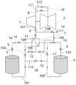
图1是本申请一实施例提出的一种切缸机组熔融盐蒸汽储热的运行系统的结构示意图。FIG. 1 is a schematic structural diagram of an operation system for molten salt vapor heat storage of a cylinder cutting unit proposed in an embodiment of the present application.
具体实施方式Detailed ways
下面详细描述本申请的实施例,所述实施例的示例在附图中示出,其中自始至终相同或类似的标号表示相同或类似的元件或具有相同或类似功能的元件。下面通过参考附图描述的实施例是示例性的,仅用于解释本申请,而不能理解为对本申请的限制。相反,本申请的实施例包括落入所附加权利要求书的精神和内涵范围内的所有变化、修改和等同物。The following describes in detail the embodiments of the present application, examples of which are illustrated in the accompanying drawings, wherein the same or similar reference numerals refer to the same or similar elements or elements having the same or similar functions throughout. The embodiments described below with reference to the accompanying drawings are exemplary and are only used to explain the present application, but should not be construed as a limitation on the present application. On the contrary, the embodiments of the present application include all changes, modifications and equivalents falling within the spirit and scope of the appended claims.
图1是本申请一实施例提出的一种切缸机组熔融盐蒸汽储热的运行系统结构示意图。FIG. 1 is a schematic structural diagram of an operation system of molten salt vapor heat storage of a cylinder cutting unit proposed in an embodiment of the present application.
参见图1,一种切缸机组熔融盐蒸汽储热的运行系统,包括熔盐换热器7、第三管道103、第四管道104、第五管道105、汽轮机中压缸1,熔盐换热器7分别通过第一管道101和第二管道102连接高温熔盐罐3和低温熔盐罐4,第三管道103的一端与熔盐换热器7相连,另一端与高温熔盐罐3相连,第四管道104的一端与熔盐换热器7相连,另一端与低温熔盐罐4相连,第五管道105的一端与熔盐换热器7相连,另一端外接待供热设备,第五管道105上连接有第六管道106,第六管道106的一端外接除氧器,汽轮机中压缸1上连接有第七管道107,第七管道107的一端分别连接有第八管道108和第九管道109,第八管道108和第九管道109的一端分别与待供热设备和熔盐换热器7相连。Referring to Fig. 1, an operation system for molten salt steam heat storage of a cylinder cutting unit includes a molten
可以理解的是,在不同的情况下进行不同的调节,实现不同形式的储热和供热,具体调节情况如下:It can be understood that different adjustments are made under different circumstances to achieve different forms of heat storage and heat supply. The specific adjustment conditions are as follows:
第一种情况:在供热负荷较低且机组电负荷较低时,可以连通第一管道101和第二管道102,关闭第三管道103和第四管道104,同时连通第七管道107和第九管道109,关闭第八管道108,使得汽轮机中压缸1的排汽先进入熔盐换热器7释放出蒸汽显热后再去供热,此时熔盐换热器7中存储一定的蒸汽显热,将低温熔盐罐4中的低温熔盐通过熔盐换热器7中的蒸汽显热进行加热后形成高温熔盐进入高温熔盐罐3中进行热量的存储,其中对于200MW等级机组可在切缸模式下,30%电负荷下可实现储热负荷15MW;对于300MW等级机组可在切缸模式下,30%电负荷下可实现储热负荷23MW;对于600MW等级机组可在切缸模式下,30%电负荷下可实现储热负荷55MW。The first situation: when the heating load is low and the electrical load of the unit is low, the
第二种情况:在供热负荷较低且机组电负荷较高时,根据供热负荷的实际需求,可以连通第三管道103、第四管道104,关闭第一管道101和第二管道102,同时连通第七管道107、第八管道108,关闭第九管道109和第五管道105,使得高温储盐罐3中的高温熔盐进入熔盐换热器7放热后进入低温储盐罐4,同时除氧器来的凝结水进入熔盐换热器7吸热后通过第九管道109进入第八管道108,其中汽轮机中压缸1排汽也进入第八管道108,两者一起混合后为待供热设备进行供热。The second case: when the heating load is low and the electrical load of the unit is high, according to the actual demand of the heating load, the
在一些实施例中,第一管道101和所述第二管道102上分别连接有第九阀门16和第八阀门15,第三管道103和第四管道104上分别设置有第七阀门14和第十阀门17。In some embodiments, a
可以理解的是,在第一管道101、第二管道102、第三管道103和第四管道104进行连通以及关闭是,只需要通过开闭第九阀门16、第八阀门15、第七阀门14和第十阀门17即可实现。It can be understood that, when the
在一些实施例中,第三管道103上设置有高温熔盐泵5,高温熔盐泵5位于第七阀门14和高温熔盐罐3之间。In some embodiments, the
可以理解的是,通过高温熔盐泵5能够控制高温熔盐罐中的高温熔盐进入熔盐换热器7中。It can be understood that the high temperature molten salt in the high temperature molten salt tank can be controlled to enter the molten
在一些实施例中,第四管道104上设置有低温熔盐泵6,低温熔盐泵6位于第八阀门15和低温熔盐罐4之间。In some embodiments, the
在一些实施例中,还包括第十管道110,第十管道110的一端与第一管道101相连且位于第九阀门16和高温熔盐罐3之间,第十管道110的另一端与第四管道104相连且位于第十阀门110和低温熔盐罐4之间,第十管道110上设置有第十一阀门18。In some embodiments, a
可以理解的是,当非供热期,熔融盐储热系统长期不运行时,需要保持低温储盐罐4中的熔融盐温度要高于凝结温度,此时通过启动高温熔盐泵5,关闭第八阀门15和第十阀门17,打开第七阀门14、第九阀门16和第十一阀门18,使得高温储盐罐3中的高温熔盐直接进入低温储盐罐4混合,以达到低温储盐罐4的防凝功能;在高温储盐罐3中的高温熔盐释放完后,通过连通第七管道107、第九管道109和第六管道106,关闭第八管道108和第五管道105,使得部分汽轮机中压缸1排汽进入熔盐换热器7放热后去除氧器入口,通过启动低温熔盐泵6,打开第八阀门15、第九阀门16和第十一阀门18,关闭第十阀门17、第七阀门14,使得低温熔盐罐4中的低温熔盐进入熔盐换热器7吸热后再回到低温储盐罐4中,以实现长期不运行背景下的熔融盐储热系统的安全可靠。It can be understood that when the molten salt heat storage system is not running for a long time during the non-heating period, it is necessary to keep the molten salt temperature in the low-temperature
在一些实施例中,第五管道105上设置有第六阀门13,第六管道106的一端连接在第五管道105上且位于第六阀门13和熔盐换热器7之间,第六管道106上设置有第五阀门12。In some embodiments, the
另外,第七管道107上设置有第二阀门9,第八管道108和第九管道109上分别设置有第三阀门10和第四阀门11。In addition, the
可以理解的是,在第五管道105、第六管道106、第七管道107、第八管道108、第四管道109开闭过程中可以通过调节第六阀门13、第五阀门12、第二阀门9、第三阀门10和第四阀门11实现各管路的开闭。It can be understood that, during the opening and closing process of the
在一些实施例中,汽轮机中压缸1连接汽轮机低压缸2,汽轮机中压缸1和汽轮机低压缸2之间连接有第十一管道111和第十二管道112,第十一管道111和第十二管道112上分别设置有第一阀门8和第十二阀门19。In some embodiments, the steam turbine
可以理解的是,在供热负荷较低且机组电负荷较低时,通过关闭第一阀门8,调节第十二阀门19,保持微量冷却蒸汽进入低压缸2,机组在切缸模式下稳定运行;在供热负荷较低且机组电负荷较高时,通过全开或半开第一阀门8,根据供热负荷的实际需求,实现机组在抽凝或者纯凝模式下运行。It can be understood that when the heating load is low and the electrical load of the unit is low, by closing the
在一些实施例中,还公开了一种切缸机组熔融盐蒸汽储热的运行方法,包括如下过程:In some embodiments, a method for operating molten salt vapor heat storage of a cylinder cutting unit is also disclosed, including the following processes:
供热负荷较低且机组电负荷较低时,将汽轮机中压缸1的排汽先进入熔盐换热器7释放出蒸汽显热后再通入待供热设备中进行供热,同时将低温熔盐罐4中的低温熔盐通入熔盐换热器7中以通过蒸汽显热加热后形成高温熔盐进入高温熔盐罐3中存储;When the heating load is low and the electrical load of the unit is low, the exhaust steam from the
在供热负荷较低且机组电负荷较高时,将高温储盐罐3中的高温熔盐通入熔盐换热器7中放热后进入低温储盐罐4,将除氧器来的凝结水通入熔盐换热器7中吸收高温熔盐释放的热量得到高温蒸汽,以使高温蒸汽和所述汽轮机中压缸1中一定量的排汽共同通入待供热设备中供热。When the heating load is low and the electrical load of the unit is high, the high-temperature molten salt in the high-temperature
具体来说,在供热负荷较低且机组电负荷较低时,通过关闭第一阀门8,调节第十二阀门19,保持微量冷却蒸汽进入低压缸2,机组在切缸模式下稳定运行,启动低温熔盐泵6,打开第八阀门15和第九阀门16,关闭第七阀门14、第十阀门17和第十一阀门18,使得低温储盐罐4中的低温熔盐进入熔盐换热器7吸热后进入高温储盐罐3,同时关闭第三阀门10和第五阀门12,打开第二阀门9、第四阀门11和第六阀门13,将大量汽轮机中压缸1的排汽先进入熔盐换热器7释放出蒸汽显热后再去供热,对于200MW等级机组可在切缸模式下,30%电负荷下可实现储热负荷15MW;对于300MW等级机组可在切缸模式下,30%电负荷下可实现储热负荷23MW;对于600MW等级机组可在切缸模式下,30%电负荷下可实现储热负荷55MW。Specifically, when the heating load is low and the electrical load of the unit is low, by closing the
在供热负荷较低且机组电负荷较高时,通过全开或半开第一阀门8,根据供热负荷的实际需求,实现机组在抽凝或者纯凝模式下运行,启动高温熔盐泵6,打开第七阀门14和第十阀门17,关闭第九阀门16、第八阀门15和第十一阀门18,使得高温储盐罐3中的高温熔盐进入熔盐换热器7放热后进入低温储盐罐4,关闭第六阀门13,打开第三阀门10、第四阀门11和第五阀门12,使得除氧器来的凝结水进入熔盐换热器7吸热后与适量中压缸1排汽汇合后去供热,根据供热负荷需求的变化,结合熔融盐储热系统释热的热负荷,灵活调整第二阀门9的开度,以达到电负荷的顶峰,最大可在机组保障供热的同时实现满出力。When the heating load is low and the electrical load of the unit is high, the
在一些实施例中,还包括:当非供热期,熔融盐储热系统长期不运行时,将高温熔盐罐中的高温熔盐直接通入低温熔盐罐中,在高温熔盐罐3中的高温熔盐释放完后,将汽轮机中压缸1的排汽进入熔盐换热器7释放出蒸汽显热,同时将低温熔盐罐4中的低温熔盐通入熔盐换热器7中吸收所述蒸汽显热后再通入低温熔盐罐4中。In some embodiments, it also includes: when the molten salt heat storage system does not operate for a long time during the non-heating period, directly passing the high temperature molten salt in the high temperature molten salt tank into the low temperature molten salt tank, and in the high temperature
可以理解的是,当非供热期,熔融盐储热系统长期不运行时,需要保持低温储盐罐4中的熔融盐温度要高于凝结温度,通过启动高温熔盐泵5,关闭第八阀门15和第十阀门17,打开第七阀门14、第九阀门16和第十一阀门18,使得高温储盐罐3中的高温熔盐直接进入低温储盐罐4混合,以达到低温储盐罐4的防凝功能;在高温储盐罐3中的高温熔盐释放完后,通过启动低温熔盐泵6,打开第八阀门15、第九阀门16和第十一阀门18,关闭第十阀门17、第七阀门14,使得低温熔盐进入熔盐换热器7吸热后再回到低温储盐罐4中,关闭第三阀门10和第六阀门13,调节第二阀门9、第四阀门11和第五阀门12的开度,使得部分中压缸1排汽进入熔盐换热器7放热后去除氧器入口,以实现长期不运行背景下的熔融盐储热系统的安全可靠。It can be understood that when the molten salt heat storage system does not operate for a long time during the non-heating period, it is necessary to keep the molten salt temperature in the low-temperature
综上可知,本申请在通过消纳和替代机组供热抽汽,以实现电负荷和热负荷的时空转移,同时可利用蒸汽进行熔融盐储热装置的防凝,从而达到机组的灵活运行,实现了机组更深度的热电解耦,更好适应当前电力系统需求。To sum up, the present application realizes the time-space transfer of electrical load and thermal load by absorbing and replacing the unit heat supply and steam extraction, and at the same time, the steam can be used for the anti-condensation of the molten salt heat storage device, so as to achieve the flexible operation of the unit. It realizes a deeper thermal and electrolytic coupling of the unit, and better adapts to the current power system needs.
需要说明的是,在本申请的描述中,术语“第一”、“第二”等仅用于描述目的,而不能理解为指示或暗示相对重要性。此外,在本申请的描述中,除非另有说明,“多个”的含义是两个或两个以上。It should be noted that, in the description of the present application, the terms "first", "second" and the like are only used for the purpose of description, and should not be construed as indicating or implying relative importance. Also, in the description of this application, unless otherwise specified, "plurality" means two or more.
流程图中或在此以其他方式描述的任何过程或方法描述可以被理解为,表示包括一个或更多个用于实现特定逻辑功能或过程的步骤的可执行指令的代码的模块、片段或部分,并且本申请的优选实施方式的范围包括另外的实现,其中可以不按所示出或讨论的顺序,包括根据所涉及的功能按基本同时的方式或按相反的顺序,来执行功能,这应被本申请的实施例所属技术领域的技术人员所理解。Any description of a process or method in the flowcharts or otherwise described herein may be understood to represent a module, segment or portion of code comprising one or more executable instructions for implementing a specified logical function or step of the process , and the scope of the preferred embodiments of the present application includes alternative implementations in which the functions may be performed out of the order shown or discussed, including performing the functions substantially concurrently or in the reverse order depending upon the functions involved, which should It is understood by those skilled in the art to which the embodiments of the present application belong.
在本说明书的描述中,参考术语“一个实施例”、“一些实施例”、“示例”、“具体示例”、或“一些示例”等的描述意指结合该实施例或示例描述的具体特征、结构、材料或者特点包含于本申请的至少一个实施例或示例中。在本说明书中,对上述术语的示意性表述不一定指的是相同的实施例或示例。而且,描述的具体特征、结构、材料或者特点可以在任何的一个或多个实施例或示例中以合适的方式结合。In the description of this specification, description with reference to the terms "one embodiment," "some embodiments," "example," "specific example," or "some examples", etc., mean specific features described in connection with the embodiment or example , structure, material or feature is included in at least one embodiment or example of the present application. In this specification, schematic representations of the above terms do not necessarily refer to the same embodiment or example. Furthermore, the particular features, structures, materials or characteristics described may be combined in any suitable manner in any one or more embodiments or examples.
尽管上面已经示出和描述了本申请的实施例,可以理解的是,上述实施例是示例性的,不能理解为对本申请的限制,本领域的普通技术人员在本申请的范围内可以对上述实施例进行变化、修改、替换和变型。Although the embodiments of the present application have been shown and described above, it should be understood that the above embodiments are exemplary and should not be construed as limitations to the present application. Embodiments are subject to variations, modifications, substitutions and variations.
Claims (10)
Priority Applications (2)
| Application Number | Priority Date | Filing Date | Title |
|---|---|---|---|
| CN202210542172.6ACN114876596B (en) | 2022-05-18 | 2022-05-18 | An operating system and method for heat storage of molten salt steam in a cylinder cutting unit |
| PCT/CN2022/101601WO2023221244A1 (en) | 2022-05-18 | 2022-06-27 | Molten salt steam heat storage operating system and method for cylinder cutting unit |
Applications Claiming Priority (1)
| Application Number | Priority Date | Filing Date | Title |
|---|---|---|---|
| CN202210542172.6ACN114876596B (en) | 2022-05-18 | 2022-05-18 | An operating system and method for heat storage of molten salt steam in a cylinder cutting unit |
Publications (2)
| Publication Number | Publication Date |
|---|---|
| CN114876596Atrue CN114876596A (en) | 2022-08-09 |
| CN114876596B CN114876596B (en) | 2023-05-23 |
Family
ID=82675160
Family Applications (1)
| Application Number | Title | Priority Date | Filing Date |
|---|---|---|---|
| CN202210542172.6AActiveCN114876596B (en) | 2022-05-18 | 2022-05-18 | An operating system and method for heat storage of molten salt steam in a cylinder cutting unit |
Country Status (2)
| Country | Link |
|---|---|
| CN (1) | CN114876596B (en) |
| WO (1) | WO2023221244A1 (en) |
Families Citing this family (3)
| Publication number | Priority date | Publication date | Assignee | Title |
|---|---|---|---|---|
| CN117628959A (en)* | 2024-01-04 | 2024-03-01 | 陕西榆林能源集团杨伙盘煤电有限公司 | A molten salt heat storage depth peak-shaving system |
| CN118960456A (en)* | 2024-07-29 | 2024-11-15 | 华能国际电力股份有限公司德州电厂 | External steam supply system and method for cascade utilization of high-temperature steam heat energy |
| CN118936184B (en)* | 2024-09-13 | 2025-09-16 | 西安热工研究院有限公司 | A system and method for improving the efficiency and reliability of molten salt thermal storage energy utilization |
Citations (8)
| Publication number | Priority date | Publication date | Assignee | Title |
|---|---|---|---|---|
| CN205823355U (en)* | 2016-06-12 | 2016-12-21 | 铂瑞能源环境工程有限公司 | A kind of co-generation unit |
| CN110206603A (en)* | 2019-05-16 | 2019-09-06 | 浙江浙能技术研究院有限公司 | A kind of fired power generating unit thermoelectricity decoupling system and method based on steam heating fused salt accumulation of heat |
| CN111365086A (en)* | 2020-05-07 | 2020-07-03 | 西安西热节能技术有限公司 | Shutdown non-shutdown system and method based on molten salt heat storage |
| CN112610292A (en)* | 2020-12-11 | 2021-04-06 | 北京前沿动力科技股份有限公司 | Deep peak regulation power generation system |
| CN113623032A (en)* | 2021-09-13 | 2021-11-09 | 西安交通大学 | Coal-fired boiler flue gas heat storage and power generation integrated system and operation method |
| CN113864014A (en)* | 2021-10-26 | 2021-12-31 | 西安热工研究院有限公司 | Thermal power heat exchange molten salt energy storage black start system |
| CN114233417A (en)* | 2021-12-22 | 2022-03-25 | 斯玛特储能技术有限公司 | Heat storage type deep flexible peak regulation thermal power generation system and heat storage and release method |
| CN114251142A (en)* | 2021-12-14 | 2022-03-29 | 西安热工研究院有限公司 | An elastic heat storage type rapid peak regulation and medium pressure heating system and method |
Family Cites Families (6)
| Publication number | Priority date | Publication date | Assignee | Title |
|---|---|---|---|---|
| US4037579A (en)* | 1976-01-26 | 1977-07-26 | Chubb Talbot A | Energy storage-boiler tank using salt fusion and heat piping |
| JP2014092086A (en)* | 2012-11-05 | 2014-05-19 | Hitachi Ltd | Solar heat power plant, and solar heat storage and radiation apparatus |
| CN103868389A (en)* | 2014-03-13 | 2014-06-18 | 北京工业大学 | Independent fused salt heat storage power plant |
| CN104406152A (en)* | 2014-11-05 | 2015-03-11 | 江苏太阳宝新能源有限公司 | Method for modifying thermal power station by storing energy through fused salt and device of method |
| CN110006026B (en)* | 2019-04-18 | 2023-10-17 | 北京工业大学 | Deep peak regulation system of thermal power plant |
| CN111140296B (en)* | 2020-02-25 | 2024-02-06 | 中国电力工程顾问集团华东电力设计院有限公司 | A molten salt cascade energy storage and discharge peaking system and method for thermal power units |
- 2022
- 2022-05-18CNCN202210542172.6Apatent/CN114876596B/enactiveActive
- 2022-06-27WOPCT/CN2022/101601patent/WO2023221244A1/ennot_activeCeased
Patent Citations (8)
| Publication number | Priority date | Publication date | Assignee | Title |
|---|---|---|---|---|
| CN205823355U (en)* | 2016-06-12 | 2016-12-21 | 铂瑞能源环境工程有限公司 | A kind of co-generation unit |
| CN110206603A (en)* | 2019-05-16 | 2019-09-06 | 浙江浙能技术研究院有限公司 | A kind of fired power generating unit thermoelectricity decoupling system and method based on steam heating fused salt accumulation of heat |
| CN111365086A (en)* | 2020-05-07 | 2020-07-03 | 西安西热节能技术有限公司 | Shutdown non-shutdown system and method based on molten salt heat storage |
| CN112610292A (en)* | 2020-12-11 | 2021-04-06 | 北京前沿动力科技股份有限公司 | Deep peak regulation power generation system |
| CN113623032A (en)* | 2021-09-13 | 2021-11-09 | 西安交通大学 | Coal-fired boiler flue gas heat storage and power generation integrated system and operation method |
| CN113864014A (en)* | 2021-10-26 | 2021-12-31 | 西安热工研究院有限公司 | Thermal power heat exchange molten salt energy storage black start system |
| CN114251142A (en)* | 2021-12-14 | 2022-03-29 | 西安热工研究院有限公司 | An elastic heat storage type rapid peak regulation and medium pressure heating system and method |
| CN114233417A (en)* | 2021-12-22 | 2022-03-25 | 斯玛特储能技术有限公司 | Heat storage type deep flexible peak regulation thermal power generation system and heat storage and release method |
Also Published As
| Publication number | Publication date |
|---|---|
| CN114876596B (en) | 2023-05-23 |
| WO2023221244A1 (en) | 2023-11-23 |
Similar Documents
| Publication | Publication Date | Title |
|---|---|---|
| CN106196697B (en) | Thermoelectricity unit and its peak regulating method associated with steam drive heat pump and regenerative apparatus | |
| CN106287902B (en) | Combined heat and power unit combined with electric heat pump and heat storage device and its peak regulation method | |
| CN114876596A (en) | Operation system and method for fused salt steam heat storage of cylinder cutting unit | |
| CN111577410B (en) | Gas turbine inlet air temperature control device and gas turbine inlet air temperature control method | |
| CN114704815A (en) | Vapor heat storage system | |
| CN114992619B (en) | A combined heat and power unit based on molten salt heat storage | |
| CN107940538A (en) | A kind of classification hold over system and its peak regulating method for cogeneration units | |
| CN103953402A (en) | Solar energy and biomass energy combined power generation optimizing integrated system | |
| CN112611010B (en) | A kind of regulation method for flexible regulation system of power generation load of multi-heat source cogeneration unit | |
| CN208519750U (en) | A kind of thermal power plant's fused salt accumulation of heat peak regulation system heated using main steam | |
| CN217712695U (en) | Industry supplies vapour system based on fused salt energy storage | |
| CN116658267A (en) | Solar-assisted cogeneration system and operation method | |
| CN108361679A (en) | The system and method energized using Proton Exchange Membrane Fuel Cells and gas turbine waste heat | |
| CN106401679B (en) | Thermoelectric unit with peak regulation and heat storage functions | |
| CN114110714A (en) | Low-pressure cylinder low-flow working condition waste heat deep recovery heat supply system and application method thereof | |
| CN207728409U (en) | Three-exhauster 200MW unit mesolow cylinders combine zero output heating system | |
| CN117846908A (en) | Solar energy coupled geothermal energy low-temperature heat cogeneration system and method | |
| CN114718676B (en) | Heat storage and release system for fused salt heated by coal-fired unit steam | |
| CN114963281B (en) | Cogeneration system and operation method for coupling energy storage system and coal-fired unit | |
| CN117248979A (en) | Multi-temperature-zone heat storage power generation system and operation method | |
| CN116398296A (en) | A Precise Heat Extraction Combined Cycle Air Intake Cooling Heating Cycle System | |
| CN214221275U (en) | An extraction steam cogeneration unit suitable for primary frequency modulation of large extraction steam | |
| CN115306502A (en) | Thermal power generation system and operation method thereof | |
| CN211781370U (en) | Solar-assisted coal-fired cogeneration system based on absorption heat pump | |
| CN112383077A (en) | New energy coupling thermal power generating unit power generation energy storage peak regulation combined system and operation method |
Legal Events
| Date | Code | Title | Description |
|---|---|---|---|
| PB01 | Publication | ||
| PB01 | Publication | ||
| SE01 | Entry into force of request for substantive examination | ||
| SE01 | Entry into force of request for substantive examination | ||
| GR01 | Patent grant | ||
| GR01 | Patent grant |