CN114876218A - Synchronous reinforcing structure and reinforcing method for building beam column - Google Patents
Synchronous reinforcing structure and reinforcing method for building beam columnDownload PDFInfo
- Publication number
- CN114876218A CN114876218ACN202210460468.3ACN202210460468ACN114876218ACN 114876218 ACN114876218 ACN 114876218ACN 202210460468 ACN202210460468 ACN 202210460468ACN 114876218 ACN114876218 ACN 114876218A
- Authority
- CN
- China
- Prior art keywords
- reinforcing
- module
- guide
- rod
- beam column
- Prior art date
- Legal status (The legal status is an assumption and is not a legal conclusion. Google has not performed a legal analysis and makes no representation as to the accuracy of the status listed.)
- Granted
Links
Images


Classifications
- E—FIXED CONSTRUCTIONS
- E04—BUILDING
- E04G—SCAFFOLDING; FORMS; SHUTTERING; BUILDING IMPLEMENTS OR AIDS, OR THEIR USE; HANDLING BUILDING MATERIALS ON THE SITE; REPAIRING, BREAKING-UP OR OTHER WORK ON EXISTING BUILDINGS
- E04G21/00—Preparing, conveying, or working-up building materials or building elements in situ; Other devices or measures for constructional work
- E04G21/14—Conveying or assembling building elements
- E04G21/16—Tools or apparatus
- E04G21/18—Adjusting tools; Templates
- E04G21/1841—Means for positioning building parts or elements
Landscapes
- Engineering & Computer Science (AREA)
- Architecture (AREA)
- Mechanical Engineering (AREA)
- Civil Engineering (AREA)
- Structural Engineering (AREA)
- Conveying And Assembling Of Building Elements In Situ (AREA)
Abstract
Translated fromChinese
Description
Translated fromChinese技术领域technical field
本发明涉及高端装备制造领域,尤其涉及一种建筑梁柱同步加固结构及加固方法。The invention relates to the field of high-end equipment manufacturing, in particular to a synchronous reinforcement structure of building beams and columns and a reinforcement method.
背景技术Background technique
建筑梁作为建筑物的主要构件,在保证整个建筑物的稳定性中发挥着重要作用。其中,为了便于建筑过程中的搭建设计,往往会采用梁柱结构。为了便于梁柱机构之间的配装,往往会采用同步加固结构对梁柱连接处进行加固。As the main component of a building, building beams play an important role in ensuring the stability of the entire building. Among them, in order to facilitate the construction design in the construction process, beam-column structures are often used. In order to facilitate the assembly between beam-column mechanisms, a synchronous reinforcement structure is often used to reinforce the beam-column connection.
然而,现有的建筑梁柱同步加固结构在使用过程中不便于多个方向上的配合固定,进而形成更为稳定的同步加固。因此,急需设计出一种新型建筑梁柱同步加固结构及相应加固方法。However, the existing building beam-column synchronous reinforcement structure is inconvenient to cooperate and fix in multiple directions during use, thereby forming a more stable synchronous reinforcement. Therefore, it is urgent to design a new type of building beam-column synchronous reinforcement structure and a corresponding reinforcement method.
发明内容SUMMARY OF THE INVENTION
本发明所要解决的技术问题在于提供一种新型建筑梁柱同步加固结构及加固方法,以避免采用现有同步加固结构进行建筑梁柱加固时带来的不便于多个方向上的配合固定问题。The technical problem to be solved by the present invention is to provide a novel building beam-column synchronous reinforcement structure and a reinforcement method, so as to avoid the problem of inconvenient coordination and fixation in multiple directions when using the existing synchronous reinforcement structure for building beam-column reinforcement.
本发明采用以下技术方案解决上述技术问题:The present invention adopts the following technical solutions to solve the above-mentioned technical problems:
一种建筑梁柱同步加固结构,包括梁柱主体以及夹设在所述梁柱主体外周的多向同步加工结构;所述多向同步加工结构包括端向配装加固模块和两个对称而设的侧向配装加固模块;所述端向配装加固模块布置在所述梁柱主体的一侧,两个侧向配装加固模块则连接在所述端向配装加固模块上靠近梁柱主体所在侧的左右两端,且彼此配合,共同将所述梁柱主体夹紧于其内。A building beam-column synchronous reinforcement structure includes a beam-column main body and a multi-directional synchronous processing structure sandwiched on the outer periphery of the beam-column main body; the multi-directional synchronous processing structure comprises an end-fit reinforcement module and two symmetrically arranged The side fitting reinforcement module; the end fitting reinforcement module is arranged on one side of the beam column main body, and the two lateral fitting reinforcement modules are connected on the end fitting reinforcement module close to the beam column The left and right ends of the side where the main body is located are matched with each other to jointly clamp the beam column main body therein.
作为本发明的优选方式之一,所述端向配装加固模块包括动导组块和从动组块;所述从动组块的一端与所述动导组块活动相连,其另一端分别与两个侧向配装加固模块活动相连。As one of the preferred modes of the present invention, the end-to-fit reinforcement module includes a moving guide block and a driven block; one end of the driven block is movably connected to the moving guide block, and the other end is respectively It is movably connected to two laterally fitted reinforcement modules.
作为本发明的优选方式之一,所述动导组块包括定位搭载板、吊装环、第一轴承座、配动杆、中心连杆、螺杆、第二轴承座、第一手轮轴和引导滑槽;所述定位搭载板竖向布置,且定位搭载板的顶部设置有吊装环,定位搭载板上靠近梁柱主体方向的一侧沿其长度方向自上而下依次设置有第一轴承座、引导滑槽、第二轴承座,同时,所述第一轴承座中配合有配动杆,第二轴承座中配合有第一手轮轴;其中,所述第一手轮轴的顶端向上穿过所述第二轴承座后还连接有螺杆,螺杆顶端套接有中心连杆,中心连杆顶端与所述配动杆的底端固定连接。As one of the preferred modes of the present invention, the moving guide block includes a positioning mounting plate, a hoisting ring, a first bearing seat, a moving rod, a central connecting rod, a screw rod, a second bearing seat, a first hand wheel shaft and a guide slide The positioning and carrying plate is arranged vertically, and the top of the positioning and carrying plate is provided with a hoisting ring. Guide the chute and the second bearing seat, at the same time, the first bearing seat is fitted with a moving rod, and the second bearing seat is fitted with a first hand wheel shaft; wherein the top of the first hand wheel shaft passes upward through the The second bearing seat is also connected with a screw rod, the top end of the screw rod is sleeved with a center connecting rod, and the top end of the center connecting rod is fixedly connected with the bottom end of the moving rod.
作为本发明的优选方式之一,所述从动组块包括第一配动块、第一收折拉杆、联动片、第二配动块第二收折拉杆和带动块;其中,所述第一配动块通过螺纹连接套接在所述螺杆外周,且同时,所述第一配动块的一侧与所述引导滑槽滑动连接,第一配动块的左右两端分别连接有一个第一收折拉杆,所述第一收折拉杆的一端与第一配动块转动相连,其另一端与联动片转动相连,联动片上固定有带动块;As one of the preferred modes of the present invention, the driven block includes a first moving block, a first folding pull rod, a linkage piece, a second moving block, a second folding pull rod, and a driving block; A moving block is sleeved on the outer circumference of the screw through a threaded connection, and at the same time, one side of the first moving block is slidably connected with the guide chute, and the left and right ends of the first moving block are respectively connected with one a first folding pull rod, one end of the first folding pull rod is rotatably connected with the first moving block, and the other end is rotatably connected with a linkage piece, and a driving block is fixed on the linkage piece;
所述第二配动块直接套接在所述配动杆的外周,且同时,所述第二配动块的左右两端分别连接有一个第二收折拉杆,所述第二收折拉杆的一端与第二配动块转动相连,其另一端与所述联动片转动相连。The second moving block is directly sleeved on the outer circumference of the moving rod, and at the same time, the left and right ends of the second moving block are respectively connected with a second folding pull rod, the second folding pull rod One end is rotatably connected with the second moving block, and the other end is rotatably connected with the linkage piece.
作为本发明的优选方式之一,每个所述侧向配装加固模块分别包括推导搭载输出模块、从动推导模块和延伸引导模块;所述推导搭载输出模块与所述端向配装加固模块相连,且同时,推导搭载输出模块上靠近另一组侧向配装加固模块的一侧连接有从动推导模块,所述从动推导模块末端连接有延伸引导模块。As one of the preferred modes of the present invention, each of the lateral fitting and reinforcement modules respectively includes a derivation and loading output module, a driven derivation module and an extension guide module; the derivation and loading output module and the end-side fitting and reinforcement module respectively and at the same time, a driven derivation module is connected to one side of the derivation loading output module close to the other set of lateral fitting reinforcement modules, and an extension guide module is connected to the end of the driven derivation module.
作为本发明的优选方式之一,所述推导搭载输出模块包括配装定位板、第二手轮轴、延伸搭载柱、辅助定位板和蜗杆;所述配装定位板与所述端向配装加固模块相连,且同时,配装定位板上远离另一组侧向配装加固模块的一侧设置有第二手轮轴,其另一侧设置有延伸搭载柱;其中,所述第二手轮轴穿过所述配装定位板、与之转动连接,第二手轮轴末端延伸连接有所述蜗杆;所述延伸搭载柱的左右两侧分别固定连接有一个所述辅助定位板。As one of the preferred modes of the present invention, the derivation and loading output module includes a fitting positioning plate, a second handwheel shaft, an extended loading column, an auxiliary positioning plate and a worm; the fitting positioning plate and the end fitting reinforcement The modules are connected, and at the same time, a second handwheel shaft is arranged on one side of the fitting positioning plate away from the other group of lateral fitting reinforcement modules, and an extension carrying column is arranged on the other side; wherein, the second handwheel shaft passes through The worm is extended and connected to the end of the second handwheel shaft through the fitting positioning plate and is rotatably connected to it; the auxiliary positioning plate is fixedly connected to the left and right sides of the extended carrying column respectively.
作为本发明的优选方式之一,所述从动推导模块包括配装架、蜗轮轴、收折调节推杆、中心导杆、辅助拉杆和加固臂;所述配装架设置有两个,分别固定在所述延伸搭载柱内端两侧,且每个所述配装架的内侧分别转动连接有一个蜗轮轴;每个所述蜗轮轴的一侧分别与所述蜗杆啮合连接,其另一侧则分别固定连接有一个收折调节推杆;其中,两个所述收折调节推杆上远离蜗轮轴的一端转动连接有同一个中心导杆,且所述中心导杆的两侧分别转动连接有一个辅助拉杆,每个所述辅助拉杆上远离中心导杆的一端分别转动连接有一个加固臂;所述加固臂用于夹设梁柱主体。As one of the preferred modes of the present invention, the driven derivation module includes an assembly frame, a worm gear shaft, a folding adjustment push rod, a central guide rod, an auxiliary pull rod and a rigidiser arm; the assembly frame is provided with two, respectively It is fixed on both sides of the inner end of the extended carrying column, and a worm gear shaft is rotatably connected to the inner side of each mounting frame; one side of each worm gear shaft is meshed with the worm, and the other A folding adjustment push rod is fixedly connected to the side respectively; wherein, the ends of the two folding adjustment push rods away from the worm wheel shaft are rotatably connected with the same central guide rod, and the two sides of the central guide rod are rotated respectively. An auxiliary pull rod is connected, and one end of each auxiliary pull rod away from the central guide rod is rotatably connected with a rigidiser arm; the rigidiser arm is used for clamping the main body of the beam and column.
作为本发明的优选方式之一,所述延伸引导模块包括配导板、中空引导板和限位槽;其中,所述配导板的中部开有供中心导杆横穿的导孔,配导板的两侧分别连接有一个中空引导板;每个所述中空引导板的中部分别设有中空槽,中空槽内设有限位槽,所述限位槽与所述加固臂滑动配合;此外,所述中空引导板还分别与辅助定位板固定相连。As one of the preferred modes of the present invention, the extension guide module includes a guide plate, a hollow guide plate, and a limit groove; wherein, a guide hole for the center guide rod to traverse is opened in the middle of the guide plate, and two parts of the guide plate are provided with a guide hole. The sides are respectively connected with a hollow guide plate; the middle part of each hollow guide plate is respectively provided with a hollow slot, and a limit slot is arranged in the hollow slot, and the limit slot is slidably matched with the rigidiser arm; The guide plates are also fixedly connected with the auxiliary positioning plates respectively.
作为本发明的优选方式之一,所述中心导杆与配导板的导孔为间隙配合,所述辅助定位板的一端与中空引导板焊接连接。As one of the preferred modes of the present invention, the center guide rod and the guide hole of the guide plate are in clearance fit, and one end of the auxiliary positioning plate is connected to the hollow guide plate by welding.
一种建筑梁柱的加固方法,采用上述建筑梁柱同步加固结构,包括如下步骤:A reinforcement method for building beams and columns, using the above-mentioned building beams and columns synchronous reinforcement structure, comprising the following steps:
(1)先将多向同步加工结构整体吊装到目标位置,再将操作人员同步升降至相应高度,最后,再将多向同步加工结构与梁柱主体需要连接处贴合;(1) First lift the multi-directional synchronous processing structure as a whole to the target position, then lift the operator to the corresponding height synchronously, and finally, fit the multi-directional synchronous processing structure with the beam-column main body where it needs to be connected;
(2)调节端向配装加固模块位置;(2) Adjust the position of the end-to-fit reinforcement module;
(3)调节侧向配装加固模块位置,完成侧向固定加固。(3) Adjust the position of the lateral assembly reinforcement module to complete the lateral fixation and reinforcement.
本发明相比现有技术的优点在于:Compared with the prior art, the present invention has the following advantages:
(1)本发明通过端向配装加固模块和侧向配装加固模块的配合设计,使得装置便于对梁柱连接处进行端向与侧向的多向加固,大大提高了梁柱连接处受力的辅助限位效果,避免了连接脱落,形成了受力加固;(1) In the present invention, through the cooperation design of the end-fit reinforcement module and the side-fit reinforcement module, the device facilitates the multi-directional reinforcement of the beam-column connection at the end and the side, which greatly improves the beam-column connection. The auxiliary force limit effect avoids the connection from falling off and forms a force reinforcement;
(2)本发明通过转动第一手轮轴,可带动两个侧向配装加固模块相靠近或远离,据此实现梁柱主体端向尺寸的相适应调节;同时,通过转动两个第二手轮轴,可带动同组的两个加固臂收拢或张开,据此实现梁柱主体侧向尺寸的相适应调节;据此,本发明可适用于多种尺寸的建筑梁柱加固;(2) In the present invention, by rotating the first hand wheel shaft, it can drive the two lateral fitting and reinforcing modules to approach or move away, so as to realize the adaptive adjustment of the end dimension of the main body of the beam and column; at the same time, by rotating the two second hand wheels The wheel axle can drive the two rigidiser arms of the same group to fold or unfold, thereby realizing the adaptive adjustment of the lateral dimensions of the main body of the beam and column; accordingly, the present invention can be applied to the reinforcement of building beams and columns of various sizes;
(3)本发明可通过吊装达到不同的梁柱高度,进而进行不同高度的多向同步加固。(3) The present invention can achieve different beam-column heights by hoisting, and then perform multi-directional synchronous reinforcement of different heights.
附图说明Description of drawings
为了更清楚地说明本发明实施例的技术方案,下面将对实施例描述所需要使用的附图作简单地介绍,显而易见地,下面描述中的附图仅仅是本发明的一些实施例,对于本领域普通技术人员来讲,在不付出创造性劳动的前提下,还可以根据这些附图获得其他的附图。In order to illustrate the technical solutions of the embodiments of the present invention more clearly, the following briefly introduces the accompanying drawings used in the description of the embodiments. Obviously, the drawings in the following description are only some embodiments of the present invention. For those of ordinary skill in the art, other drawings can also be obtained from these drawings without any creative effort.
图1为本发明建筑梁柱同步加固结构的整体结构示意图;Fig. 1 is the overall structure schematic diagram of the building beam-column synchronous reinforcement structure of the present invention;
图2为本发明建筑梁柱同步加固结构的局部结构示意图;Fig. 2 is the partial structure schematic diagram of the building beam-column synchronous reinforcement structure of the present invention;
图3为本发明端向配装加固模块的局部结构示意图;Fig. 3 is the partial structural schematic diagram of the end-to-end fitting reinforcement module of the present invention;
图4为本发明侧向配装加固模块的局部结构示意图;FIG. 4 is a partial structural schematic diagram of a laterally assembled reinforcement module of the present invention;
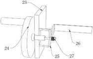
图5为本发明推导搭载输出模块的局部结构示意图;5 is a schematic diagram of the partial structure of the derivation and mounting output module of the present invention;
图6为本发明从动推导模块的局部结构示意图;Fig. 6 is the partial structure schematic diagram of the slave derivation module of the present invention;
图7为本发明延伸引导模块的局部结构示意图。FIG. 7 is a partial structural schematic diagram of the extension guide module of the present invention.
附图中,各标号所代表的部件如下:In the accompanying drawings, the components represented by each number are as follows:
1、梁柱主体;2、多向同步加工结构;3、端向配装加固模块;4、侧向配装加固模块;5、定位搭载板;6、吊装环;7、第一轴承座;8、配动杆;9、中心连杆;10、螺杆;11、第二轴承座;12、第一手轮轴;13、第一配动块;14、引导滑槽;15、第一收折拉杆;16、联动片;17、第二配动块;18、第二收折拉杆;19、带动块;20、推导搭载输出模块;21、从动推导模块;22、延伸引导模块;23、配装定位板;24、第二手轮轴;25、延伸搭载柱;26、辅助定位板;27、蜗杆;28、配装架;29、蜗轮轴;30、收折调节推杆;31、中心导杆;32、辅助拉杆;33、加固臂;34、配导板;35、中空引导板;36、限位槽。1. Main body of beam and column; 2. Multi-directional synchronous processing structure; 3. End-fit reinforcement module; 4. Side-fit reinforcement module; 5. Positioning plate; 6. Hoisting ring; 7. First bearing seat; 8. Distribution rod; 9. Central connecting rod; 10. Screw; 11. Second bearing seat; 12. First handwheel shaft; 13. First distribution block; 14. Guide chute; 15. First folding tie rod; 16, linkage piece; 17, second moving block; 18, second folding pull rod; 19, driving block; 20, derivation and carrying output module; 21, driven derivation module; 22, extension guide module; 23, Fitting and positioning plate; 24. Second handwheel shaft; 25. Extending carrying column; 26. Auxiliary positioning plate; 27. Worm; 28. Fitting frame; 29. Worm wheel shaft; Guide rod; 32, auxiliary pull rod; 33, rigidiser arm; 34, matching guide plate; 35, hollow guide plate; 36, limit slot.
具体实施方式Detailed ways
下面将结合本发明实施例中的附图,对本发明实施例中的技术方案进行清楚、完整地描述,显然,所描述的实施例仅仅是本发明一部分实施例,而不是全部的实施例。基于本发明中的实施例,本领域普通技术人员在没有作出创造性劳动前提下所获得的所有其它实施例,都属于本发明保护的范围。The technical solutions in the embodiments of the present invention will be clearly and completely described below with reference to the accompanying drawings in the embodiments of the present invention. Obviously, the described embodiments are only a part of the embodiments of the present invention, but not all of the embodiments. Based on the embodiments of the present invention, all other embodiments obtained by those of ordinary skill in the art without creative efforts shall fall within the protection scope of the present invention.
实施例一:Example 1:
请参阅图1~7,本实施例的一种建筑梁柱同步加固结构,包括梁柱主体1以及夹设在梁柱主体1外周的多向同步加工结构2;多向同步加工结构2包括端向配装加固模块3和两个对称而设的侧向配装加固模块4;其中,端向配装加固模块3布置在梁柱主体1的一侧,两个侧向配装加固模块4则连接在端向配装加固模块3上靠近梁柱主体1所在侧的左右两端,且彼此配合,共同将梁柱主体1夹紧于其内。Referring to FIGS. 1 to 7 , a building beam-column synchronous reinforcement structure in this embodiment includes a beam-column main body 1 and a multi-directional
本实施例通过端向配装加固模块和侧向配装加固模块的配合设计,使得装置便于对梁柱连接处进行端向与侧向的多向加固,大大提高了梁柱连接处受力的辅助限位效果,避免了连接脱落,形成了受力加固。In this embodiment, through the cooperation design of the end-fit reinforcement module and the side-fit reinforcement module, the device facilitates the multi-directional reinforcement of the beam-column connection at the end and the side, which greatly improves the stress resistance of the beam-column connection. The auxiliary limit effect prevents the connection from falling off and forms a force reinforcement.
具体地,本实施例中,端向配装加固模块3包括动导组块和从动组块;从动组块的一端与动导组块活动相连,其另一端分别与两个侧向配装加固模块4活动相连。Specifically, in this embodiment, the end-
进一步地,动导组块包括定位搭载板5、吊装环6、第一轴承座7、配动杆8、中心连杆9、螺杆10、第二轴承座11、第一手轮轴12和引导滑槽14;定位搭载板5竖向布置,且定位搭载板5的顶部设置有吊装环6,定位搭载板5上靠近梁柱主体1方向的一侧沿其长度方向自上而下依次设置有第一轴承座7、引导滑槽14、第二轴承座11,同时,第一轴承座7中配合有配动杆8,第二轴承座11中配合有第一手轮轴12;其中,第一手轮轴12的顶端向上穿过第二轴承座11后还连接有螺杆10,螺杆10顶端套接有中心连杆9,中心连杆9顶端与配动杆8的底端固定连接。Further, the moving guide block includes a
从动组块包括第一配动块13、第一收折拉杆15、联动片16、第二配动块17第二收折拉杆18和带动块19;其中,第一配动块13通过螺纹连接套接在螺杆10外周,且同时,第一配动块13的一侧与引导滑槽14滑动连接,第一配动块13的左右两端分别连接有一个第一收折拉杆15,第一收折拉杆15的一端与第一配动块13转动相连,其另一端与联动片16转动相连,联动片16上固定有带动块19。第二配动块17直接套接在配动杆8的外周,且同时,第二配动块17的左右两端分别连接有一个第二收折拉杆18,第二收折拉杆18的一端与第二配动块17转动相连,其另一端与联动片16转动相连。The driven block includes a first moving
本实施例中,转动第一手轮轴12,使得第一手轮轴12带动螺杆10完成转动;利用螺杆10与第一配动块13的螺纹连接,使得第一配动块13获得转矩,同时利用第一配动块13与引导滑槽14的滑动连接,使得第一配动块13处的转矩被限位形成滑动位移;接着,利用第一配动块13的滑动推导使得第一收折拉杆15进行展开或收拢,并配合联动片16、第二配动块17和第二收折拉杆18的联动设计,带动两个侧向配装加固模块4相远离或靠近,据此实现梁柱主体端向的距离调节。In this embodiment, the
具体地,本实施例中,每个侧向配装加固模块4分别包括推导搭载输出模块20、从动推导模块21和延伸引导模块22;推导搭载输出模块20与带动块19相连,且同时,推导搭载输出模块20上靠近另一组侧向配装加固模块4的一侧连接有从动推导模块21,从动推导模块21末端连接有延伸引导模块22。Specifically, in this embodiment, each lateral assembly reinforcement module 4 includes a derivation and
进一步地,推导搭载输出模块20包括配装定位板23、第二手轮轴24、延伸搭载柱25、辅助定位板26和蜗杆27;配装定位板23与带动块19相连,且同时,配装定位板23上远离另一组侧向配装加固模块4的一侧设置有第二手轮轴24,其另一侧设置有延伸搭载柱25;其中,第二手轮轴24穿过配装定位板23、与之转动连接,第二手轮轴24末端延伸连接有蜗杆27;延伸搭载柱25的左右两侧分别固定连接有一个辅助定位板26。Further, it is deduced that the
进一步地,从动推导模块21包括配装架28、蜗轮轴29、收折调节推杆30、中心导杆31、辅助拉杆32和加固臂33;配装架28设置有两个,分别固定在延伸搭载柱25内端两侧,且每个配装架28的内侧分别转动连接有一个蜗轮轴29;每个蜗轮轴29的一侧分别与蜗杆27啮合连接,其另一侧则分别固定连接有一个收折调节推杆30;其中,两个收折调节推杆30上远离蜗轮轴29的一端转动连接有同一个中心导杆31,且中心导杆31的两侧分别转动连接有一个辅助拉杆32,每个辅助拉杆32上远离中心导杆31的一端分别转动连接有一个加固臂33;加固臂33用于夹设梁柱主体1。Further, the driven
进一步地,延伸引导模块22包括配导板34、中空引导板35和限位槽36;其中,配导板34的中部开有供中心导杆31横穿的导孔,配导板34的两侧分别连接有一个中空引导板35;每个中空引导板35的中部分别设有中空槽,中空槽内设有限位槽36,限位槽36与加固臂33滑动配合;此外,中心导杆31与配导板34的导孔为间隙配合,辅助定位板26的一端与中空引导板35焊接固定。Further, the
本实施例中,转动第二手轮轴24,使得从动推导模块21带动蜗杆27完成转动;利用蜗杆27与蜗轮轴29的啮合连接,使得蜗轮轴29在蜗杆27的拨动下完成转动;利用该转动推导收折调节推杆30进行角度调节,形成延伸推导;推导中心导杆31在配导板34的辅助限位下进行位移,进而推导辅助拉杆32带动加固臂33在限位槽36的引导下完成角度调节,形成侧向上的收拢或张开,据此实现梁柱主体侧向的距离调节,大大提高了使用便捷性。In this embodiment, the second
此外,需要说明的是,当本装置侧向配装加固模块4调节至目标位置后,可通过以下结构对其当下状态进行固定:在第二手轮轴24上设置螺栓孔,同时,在配装定位板23上设置一圈螺栓固定槽,螺栓固定槽的位置与螺栓孔相应(无论第二手轮轴24如何转动,螺栓孔的位置均与螺栓固定槽的位置相应);当需要对侧向配装加固模块4位置进行固定时,将一个锁紧螺栓自螺栓孔插入,至其底端进入配装定位板23的螺栓固定槽中、并与该位置完全紧密锁紧,实现当下状态的固定。In addition, it should be noted that, after the lateral fitting and reinforcement module 4 of the device is adjusted to the target position, its current state can be fixed by the following structure: bolt holes are provided on the
实施例二:Embodiment 2:
本实施例的一种建筑梁柱的加固方法,采用上述实施例1建筑梁柱同步加固结构,包括如下步骤:A method for reinforcing beams and columns of a building in the present embodiment adopts the synchronous strengthening structure of building beams and columns in the above-mentioned embodiment 1, and includes the following steps:
第一步:将吊机钩与吊装环6连接,将多向同步加工结构2整体吊装到合适的位置处,此时通过建筑工地的升降措施,将操作人员同步升降至合适的高度,将多向同步加工结构2与梁柱主体1需要连接处贴合;The first step: connect the hoist hook with the
第二步:调节端向配装加固模块3位置,完成端向固定加固;The second step: adjust the position of the end-to-
第三步:调节侧向配装加固模块4位置,完成侧向固定加固。Step 3: Adjust the position of the lateral assembly reinforcement module 4 to complete the lateral fixation and reinforcement.
在本说明书的描述中,参考术语“一个实施例”、“示例”、“具体示例”等的描述意指结合该实施例或示例描述的具体特征、结构、材料或者特点包含于本发明的至少一个实施例或示例中。在本说明书中,对上述术语的示意性表述不一定指的是相同的实施例或示例。而且,描述的具体特征、结构、材料或者特点可以在任何的一个或多个实施例或示例中以合适的方式结合。In the description of this specification, description with reference to the terms "one embodiment," "example," "specific example," etc. means that a particular feature, structure, material, or characteristic described in connection with the embodiment or example is included in at least one aspect of the present invention. in one embodiment or example. In this specification, schematic representations of the above terms do not necessarily refer to the same embodiment or example. Furthermore, the particular features, structures, materials or characteristics described may be combined in any suitable manner in any one or more embodiments or examples.
以上公开的本发明优选实施例只是用于帮助阐述本发明。优选实施例并没有详尽叙述所有的细节,也不限制该本发明仅为所述的具体实施方式。显然,根据本说明书的内容,可作很多的修改和变化。本说明书选取并具体描述这些实施例,是为了更好地解释本发明的原理和实际应用,从而使所属技术领域技术人员能很好地理解和利用本发明。本发明仅受权利要求书及其全部范围和等效物的限制。The above-disclosed preferred embodiments of the present invention are provided only to help illustrate the present invention. The preferred embodiments do not exhaust all the details, nor do they limit the invention to only the described embodiments. Obviously, many modifications and variations are possible in light of the content of this specification. The present specification selects and specifically describes these embodiments in order to better explain the principles and practical applications of the present invention, so that those skilled in the art can well understand and utilize the present invention. The present invention is to be limited only by the claims and their full scope and equivalents.
Claims (10)
Priority Applications (1)
| Application Number | Priority Date | Filing Date | Title |
|---|---|---|---|
| CN202210460468.3ACN114876218B (en) | 2022-04-24 | 2022-04-24 | A building beam-column synchronous reinforcement structure and reinforcement method |
Applications Claiming Priority (1)
| Application Number | Priority Date | Filing Date | Title |
|---|---|---|---|
| CN202210460468.3ACN114876218B (en) | 2022-04-24 | 2022-04-24 | A building beam-column synchronous reinforcement structure and reinforcement method |
Publications (2)
| Publication Number | Publication Date |
|---|---|
| CN114876218Atrue CN114876218A (en) | 2022-08-09 |
| CN114876218B CN114876218B (en) | 2025-10-03 |
Family
ID=82672373
Family Applications (1)
| Application Number | Title | Priority Date | Filing Date |
|---|---|---|---|
| CN202210460468.3AActiveCN114876218B (en) | 2022-04-24 | 2022-04-24 | A building beam-column synchronous reinforcement structure and reinforcement method |
Country Status (1)
| Country | Link |
|---|---|
| CN (1) | CN114876218B (en) |
Cited By (1)
| Publication number | Priority date | Publication date | Assignee | Title |
|---|---|---|---|---|
| CN119266525A (en)* | 2024-12-09 | 2025-01-07 | 内蒙古智方科技有限责任公司 | A kind of building reinforcement beam column structure |
Citations (9)
| Publication number | Priority date | Publication date | Assignee | Title |
|---|---|---|---|---|
| EP1617013A1 (en)* | 2004-07-13 | 2006-01-18 | CEDEMAT - Aluguer de Materiais de Construçao, Lda | Horizontal formwork |
| WO2018103071A1 (en)* | 2016-12-09 | 2018-06-14 | 冯庆柱 | Laser welding quality monitoring apparatus |
| CN208686072U (en)* | 2018-06-12 | 2019-04-02 | 重庆新久融科技有限公司 | A kind of aluminum alloy mould plate bracing means |
| CN111751205A (en)* | 2020-08-17 | 2020-10-09 | 柴子靖 | Fabric lateral stretching performance random detection device for fabric textile processing |
| CN211851023U (en)* | 2020-03-18 | 2020-11-03 | 吴百玉 | A kind of building structural beam reinforcement structure |
| CN112431406A (en)* | 2020-11-10 | 2021-03-02 | 中土(苏州)工程建设有限公司 | Beam side template reinforcing frame |
| CN212715914U (en)* | 2020-07-03 | 2021-03-16 | 中建七局第四建筑有限公司 | Frame post template reinforcing apparatus is built in room |
| CN213390531U (en)* | 2020-08-21 | 2021-06-08 | 中交鹭建有限公司 | Reinforced concrete beam column node reinforced structure |
| WO2021231824A1 (en)* | 2020-05-14 | 2021-11-18 | Edwards Lifesciences Corporation | Prosthetic heart valve leaflet commissure assemblies and methods |
- 2022
- 2022-04-24CNCN202210460468.3Apatent/CN114876218B/enactiveActive
Patent Citations (9)
| Publication number | Priority date | Publication date | Assignee | Title |
|---|---|---|---|---|
| EP1617013A1 (en)* | 2004-07-13 | 2006-01-18 | CEDEMAT - Aluguer de Materiais de Construçao, Lda | Horizontal formwork |
| WO2018103071A1 (en)* | 2016-12-09 | 2018-06-14 | 冯庆柱 | Laser welding quality monitoring apparatus |
| CN208686072U (en)* | 2018-06-12 | 2019-04-02 | 重庆新久融科技有限公司 | A kind of aluminum alloy mould plate bracing means |
| CN211851023U (en)* | 2020-03-18 | 2020-11-03 | 吴百玉 | A kind of building structural beam reinforcement structure |
| WO2021231824A1 (en)* | 2020-05-14 | 2021-11-18 | Edwards Lifesciences Corporation | Prosthetic heart valve leaflet commissure assemblies and methods |
| CN212715914U (en)* | 2020-07-03 | 2021-03-16 | 中建七局第四建筑有限公司 | Frame post template reinforcing apparatus is built in room |
| CN111751205A (en)* | 2020-08-17 | 2020-10-09 | 柴子靖 | Fabric lateral stretching performance random detection device for fabric textile processing |
| CN213390531U (en)* | 2020-08-21 | 2021-06-08 | 中交鹭建有限公司 | Reinforced concrete beam column node reinforced structure |
| CN112431406A (en)* | 2020-11-10 | 2021-03-02 | 中土(苏州)工程建设有限公司 | Beam side template reinforcing frame |
Cited By (1)
| Publication number | Priority date | Publication date | Assignee | Title |
|---|---|---|---|---|
| CN119266525A (en)* | 2024-12-09 | 2025-01-07 | 内蒙古智方科技有限责任公司 | A kind of building reinforcement beam column structure |
Also Published As
| Publication number | Publication date |
|---|---|
| CN114876218B (en) | 2025-10-03 |
Similar Documents
| Publication | Publication Date | Title |
|---|---|---|
| CN114876218A (en) | Synchronous reinforcing structure and reinforcing method for building beam column | |
| CN116475641B (en) | Steel construction welding process equipment | |
| CN109704248A (en) | Foldable lift aircraft maintenance scaffolding unit | |
| CN114934594B (en) | But high strength steel structure truss of fast assembly | |
| CN114013625B (en) | Can dismantle fixed wing unmanned aerial vehicle | |
| CN118997392A (en) | High-altitude assembly system of large-span cantilever truss and construction method | |
| CN103526942A (en) | Concrete pump truck and arm frame connecting mechanism thereof | |
| CN212836808U (en) | Adjustable anti-seismic reinforcing plate for building engineering | |
| CN118323487A (en) | A flexible solar wing folding and unfolding mechanism based on pod poles | |
| CN117867979B (en) | Steel pipe arch bridge arch rib folding device | |
| CN113669068A (en) | Mid-partition installation process suitable for tunnel | |
| CN217279221U (en) | A splicing type adjustable lighting system for film and television | |
| CN212577892U (en) | Turnover device for welding standard section of tower crane | |
| WO2019180167A1 (en) | Mobile crane with two-part jib, and method for aligning the boom system of such a mobile crane | |
| CN115459140A (en) | A kind of power equipment failure maintenance equipment | |
| CN111852178B (en) | Special safety fence for converter station | |
| CN203255939U (en) | Universal adjustable type hoist high-place operation platform | |
| CN219365431U (en) | A fastening device for a formwork | |
| CN207670484U (en) | A kind of individual wheel omnidirectional steering structure | |
| CN115929060B (en) | A reinforcement device and reinforcement method for assembled building door-shaped components | |
| CN115613725B (en) | Lever bridge type mixed two-stage amplifying damper | |
| CN221723757U (en) | A radar lifting mechanism | |
| CN116131145B (en) | Skid-mounted electric control integrated transformer substation assembly structure and assembly method | |
| CN213005142U (en) | Manual adjustable support | |
| CN222612744U (en) | Installation orthotic devices of large-span steel truss |
Legal Events
| Date | Code | Title | Description |
|---|---|---|---|
| PB01 | Publication | ||
| PB01 | Publication | ||
| SE01 | Entry into force of request for substantive examination | ||
| SE01 | Entry into force of request for substantive examination | ||
| GR01 | Patent grant |