CN114872649A - Power Management Devices, Vehicle Power Supplies, and Vehicles - Google Patents
Power Management Devices, Vehicle Power Supplies, and VehiclesDownload PDFInfo
- Publication number
- CN114872649A CN114872649ACN202210614680.0ACN202210614680ACN114872649ACN 114872649 ACN114872649 ACN 114872649ACN 202210614680 ACN202210614680 ACN 202210614680ACN 114872649 ACN114872649 ACN 114872649A
- Authority
- CN
- China
- Prior art keywords
- module
- voltage conversion
- output interface
- power
- power supply
- Prior art date
- Legal status (The legal status is an assumption and is not a legal conclusion. Google has not performed a legal analysis and makes no representation as to the accuracy of the status listed.)
- Pending
Links
Images


Classifications
- B—PERFORMING OPERATIONS; TRANSPORTING
- B60—VEHICLES IN GENERAL
- B60R—VEHICLES, VEHICLE FITTINGS, OR VEHICLE PARTS, NOT OTHERWISE PROVIDED FOR
- B60R16/00—Electric or fluid circuits specially adapted for vehicles and not otherwise provided for; Arrangement of elements of electric or fluid circuits specially adapted for vehicles and not otherwise provided for
- B60R16/02—Electric or fluid circuits specially adapted for vehicles and not otherwise provided for; Arrangement of elements of electric or fluid circuits specially adapted for vehicles and not otherwise provided for electric constitutive elements
- B60R16/03—Electric or fluid circuits specially adapted for vehicles and not otherwise provided for; Arrangement of elements of electric or fluid circuits specially adapted for vehicles and not otherwise provided for electric constitutive elements for supply of electrical power to vehicle subsystems or for
- B60R16/033—Electric or fluid circuits specially adapted for vehicles and not otherwise provided for; Arrangement of elements of electric or fluid circuits specially adapted for vehicles and not otherwise provided for electric constitutive elements for supply of electrical power to vehicle subsystems or for characterised by the use of electrical cells or batteries
- H—ELECTRICITY
- H02—GENERATION; CONVERSION OR DISTRIBUTION OF ELECTRIC POWER
- H02J—CIRCUIT ARRANGEMENTS OR SYSTEMS FOR SUPPLYING OR DISTRIBUTING ELECTRIC POWER; SYSTEMS FOR STORING ELECTRIC ENERGY
- H02J7/00—Circuit arrangements for charging or depolarising batteries or for supplying loads from batteries
- H02J7/0063—Circuit arrangements for charging or depolarising batteries or for supplying loads from batteries with circuits adapted for supplying loads from the battery
- H—ELECTRICITY
- H02—GENERATION; CONVERSION OR DISTRIBUTION OF ELECTRIC POWER
- H02J—CIRCUIT ARRANGEMENTS OR SYSTEMS FOR SUPPLYING OR DISTRIBUTING ELECTRIC POWER; SYSTEMS FOR STORING ELECTRIC ENERGY
- H02J7/00—Circuit arrangements for charging or depolarising batteries or for supplying loads from batteries
- H02J7/007—Regulation of charging or discharging current or voltage
- H—ELECTRICITY
- H02—GENERATION; CONVERSION OR DISTRIBUTION OF ELECTRIC POWER
- H02M—APPARATUS FOR CONVERSION BETWEEN AC AND AC, BETWEEN AC AND DC, OR BETWEEN DC AND DC, AND FOR USE WITH MAINS OR SIMILAR POWER SUPPLY SYSTEMS; CONVERSION OF DC OR AC INPUT POWER INTO SURGE OUTPUT POWER; CONTROL OR REGULATION THEREOF
- H02M1/00—Details of apparatus for conversion
- H02M1/0083—Converters characterised by their input or output configuration
- H02M1/009—Converters characterised by their input or output configuration having two or more independently controlled outputs
- H—ELECTRICITY
- H02—GENERATION; CONVERSION OR DISTRIBUTION OF ELECTRIC POWER
- H02M—APPARATUS FOR CONVERSION BETWEEN AC AND AC, BETWEEN AC AND DC, OR BETWEEN DC AND DC, AND FOR USE WITH MAINS OR SIMILAR POWER SUPPLY SYSTEMS; CONVERSION OF DC OR AC INPUT POWER INTO SURGE OUTPUT POWER; CONTROL OR REGULATION THEREOF
- H02M3/00—Conversion of DC power input into DC power output
- H02M3/02—Conversion of DC power input into DC power output without intermediate conversion into AC
- H02M3/04—Conversion of DC power input into DC power output without intermediate conversion into AC by static converters
- H02M3/10—Conversion of DC power input into DC power output without intermediate conversion into AC by static converters using discharge tubes with control electrode or semiconductor devices with control electrode
- H02M3/145—Conversion of DC power input into DC power output without intermediate conversion into AC by static converters using discharge tubes with control electrode or semiconductor devices with control electrode using devices of a triode or transistor type requiring continuous application of a control signal
- H02M3/155—Conversion of DC power input into DC power output without intermediate conversion into AC by static converters using discharge tubes with control electrode or semiconductor devices with control electrode using devices of a triode or transistor type requiring continuous application of a control signal using semiconductor devices only
- H02M3/156—Conversion of DC power input into DC power output without intermediate conversion into AC by static converters using discharge tubes with control electrode or semiconductor devices with control electrode using devices of a triode or transistor type requiring continuous application of a control signal using semiconductor devices only with automatic control of output voltage or current, e.g. switching regulators
- H02M3/158—Conversion of DC power input into DC power output without intermediate conversion into AC by static converters using discharge tubes with control electrode or semiconductor devices with control electrode using devices of a triode or transistor type requiring continuous application of a control signal using semiconductor devices only with automatic control of output voltage or current, e.g. switching regulators including plural semiconductor devices as final control devices for a single load
- H02M3/1582—Buck-boost converters
- Y—GENERAL TAGGING OF NEW TECHNOLOGICAL DEVELOPMENTS; GENERAL TAGGING OF CROSS-SECTIONAL TECHNOLOGIES SPANNING OVER SEVERAL SECTIONS OF THE IPC; TECHNICAL SUBJECTS COVERED BY FORMER USPC CROSS-REFERENCE ART COLLECTIONS [XRACs] AND DIGESTS
- Y02—TECHNOLOGIES OR APPLICATIONS FOR MITIGATION OR ADAPTATION AGAINST CLIMATE CHANGE
- Y02T—CLIMATE CHANGE MITIGATION TECHNOLOGIES RELATED TO TRANSPORTATION
- Y02T10/00—Road transport of goods or passengers
- Y02T10/80—Technologies aiming to reduce greenhouse gasses emissions common to all road transportation technologies
- Y02T10/92—Energy efficient charging or discharging systems for batteries, ultracapacitors, supercapacitors or double-layer capacitors specially adapted for vehicles
Landscapes
- Engineering & Computer Science (AREA)
- Power Engineering (AREA)
- Mechanical Engineering (AREA)
- Direct Current Feeding And Distribution (AREA)
Abstract
Description
Translated fromChinese技术领域technical field
本公开涉及电源管理技术领域,具体而言,涉及一种电源管理装置、车载电源及车辆。The present disclosure relates to the technical field of power management, and in particular, to a power management device, a vehicle power supply, and a vehicle.
背景技术Background technique
随着自动驾驶技术的发展,自动驾驶汽车开始走进人们的日常生活,自动驾驶汽车的供电问题越来越被重视。在自动驾驶汽车启动后,即可通过车载蓄电池对车辆中的各类负载(如各类传感器以及显示屏)进行供电。With the development of self-driving technology, self-driving cars have begun to enter people's daily life, and the issue of power supply for self-driving cars has been paid more and more attention. After the self-driving car starts, it can supply power to various loads in the vehicle (such as various sensors and display screens) through the on-board battery.
然而,相关技术中,在接收到车辆启动信号后,会同时对各类负载进行供电,进而会出现因上电时序错乱而引发的系统供电故障问题。However, in the related art, after the vehicle start signal is received, power is supplied to various loads at the same time, and a system power supply failure problem caused by disordered power-on sequence may occur.
发明内容SUMMARY OF THE INVENTION
有鉴于此,本公开的目的在于提供一种电源管理装置、车载电源及车辆。In view of this, the purpose of the present disclosure is to provide a power management device, a vehicle power supply and a vehicle.
本公开实施例提供了一种电源管理装置,用于转换供电装置输出的电源信号为各类负载供电;所述电源管理装置包括选择单元、主控模块以及多个电压转换模块;An embodiment of the present disclosure provides a power management device for converting a power signal output by a power supply device to supply power to various loads; the power management device includes a selection unit, a main control module, and a plurality of voltage conversion modules;
所述选择单元,分别与所述主控模块以及所述多个电压转换模块中的目标电压转换模块连接,所述选择单元用于接收车辆启动信号,并根据所述车辆启动信号控制所述目标电压转换模块上电工作,进而为所述主控模块提供工作电压,使得所述主控模块上电工作;The selection unit is respectively connected with the main control module and the target voltage conversion module in the plurality of voltage conversion modules, and the selection unit is used for receiving a vehicle start signal and controlling the target according to the vehicle start signal The voltage conversion module is powered on to work, and then provides a working voltage for the main control module, so that the main control module is powered on and works;
所述主控模块还分别与除所述目标电压转换模块之外的其他电压转换模块连接,所述主控模块上电工作后,所述主控模块用于控制所述其他电压转换模块按照预设的上电时序依次上电工作。The main control module is also connected to other voltage conversion modules except the target voltage conversion module. After the main control module is powered on and works, the main control module is used to control the other voltage conversion modules according to the preset. The set power-on sequence is powered on in sequence.
本公开实施例中,选择单元分别与主控模块以及目标电压转换模块连接,用于接收车辆启动信号,并根据车辆启动信号控制目标电压转换模块上电工作,进而为主控模块提供工作电压,使得主控模块上电工作,同时主控模块可以控制其他电压转换模块按照预设的上电时序依次上电工作,如此,可以进一步使得各类负载能够有序上电,减少了因上电时序错乱引发的系统供电问题的发生。In the embodiment of the present disclosure, the selection unit is respectively connected to the main control module and the target voltage conversion module, and is used to receive the vehicle start signal, and control the target voltage conversion module to work according to the vehicle start signal, so as to provide the main control module with a working voltage, The main control module is powered on to work, and the main control module can control other voltage conversion modules to power on and work in sequence according to the preset power-on sequence. In this way, various loads can be powered on in an orderly manner, reducing the power-on sequence caused by the power-on sequence. The occurrence of system power supply problems caused by confusion.
在一种可能的实施方式中,所述主控模块用于接收车辆关闭信号,并根据所述车辆关闭信号控制所述其他电压转换模块按照预设的下电时序依次下电停止工作。In a possible implementation manner, the main control module is configured to receive a vehicle shutdown signal, and control the other voltage conversion modules to power off and stop working in sequence according to a preset power off sequence according to the vehicle shutdown signal.
本公开实施例中,主控模块在接收到车辆关闭信号后,可以控制其他电压转换模块按照预设的下电时序依次下电停止工作,如此,可以进一步使得各类负载能够有序下电,实现下电工作的自动化,减少了系统供电故障问题发生的概率。In the embodiment of the present disclosure, after receiving the vehicle shutdown signal, the main control module can control the other voltage conversion modules to power off and stop working in sequence according to the preset power off sequence. In this way, various loads can be powered off in an orderly manner. The automation of power-off work is realized and the probability of system power supply failure is reduced.
在一种可能的实施方式中,所述多个电压转换模块包括至少一个第一电压转换模块以及至少一个第二电压转换模块,所述目标电压转换模块为所述至少一个第一电压转换模块中的电压转换模块;In a possible implementation manner, the plurality of voltage conversion modules include at least one first voltage conversion module and at least one second voltage conversion module, and the target voltage conversion module is one of the at least one first voltage conversion module the voltage conversion module;
所述至少一个第一电压转换模块,分别与所述供电装置连接,每个第一电压转换模块用于将所述电源信号转换成第一电压信号以为第一类型的负载供电;The at least one first voltage conversion module is respectively connected to the power supply device, and each first voltage conversion module is used to convert the power signal into a first voltage signal to supply power for a first type of load;
所述至少一个第二电压转换模块,分别与所述供电装置连接,每个第二电压转换模块用于将所述电源信号转换成第二电压信号以为第二类型的负载供电;其中,所述第一电压信号小于所述第二电压信号。The at least one second voltage conversion module is respectively connected to the power supply device, and each second voltage conversion module is used to convert the power signal into a second voltage signal to supply power for a second type of load; wherein, the The first voltage signal is smaller than the second voltage signal.
本公开实施例中,由于多个电压转换模块包括至少一个第一电压转换模块以及至少一个第二电压转换模块,且第一电压转换模块用于将电源信号转换成第一电压信号,第二电压转换模块用于将电源信号转换成第二电压信号,如此,可以实现不同负载的不同供电需求,以使得每个负载都能正常工作。In the embodiment of the present disclosure, since the plurality of voltage conversion modules include at least one first voltage conversion module and at least one second voltage conversion module, and the first voltage conversion module is used to convert the power signal into the first voltage signal, the second voltage The conversion module is used to convert the power signal into the second voltage signal, so that different power supply requirements of different loads can be realized, so that each load can work normally.
在一种可能的实施方式中,所述电源管理装置还包括至少一个第一输出接口以及至少一个第二输出接口;In a possible implementation manner, the power management apparatus further includes at least one first output interface and at least one second output interface;
所述至少一个第一输出接口的数量与所述至少一个第一电压转换模块的数量相同且一一对应,所述第一输出接口用于将所述第一电压信号输出,以为所述第一类型的负载供电;The number of the at least one first output interface is the same as the number of the at least one first voltage conversion module and has a one-to-one correspondence, and the first output interface is used to output the first voltage signal as the first voltage signal. type of load power supply;
所述至少一个第二输出接口的数量与所述至少一个第二电压转换模块的数量相同且一一对应,所述第二输出接口用于将所述第二电压信号输出,以为所述第二类型的负载供电;The number of the at least one second output interface is the same as the number of the at least one second voltage conversion module and is in one-to-one correspondence, and the second output interface is used to output the second voltage signal as the second voltage signal. type of load power supply;
所述至少一个第一电压转换模块、所述至少一个第一输出接口、所述至少一个第二电压转换模块以及所述至少一个第二输出接口集成于同一印制电路板。The at least one first voltage conversion module, the at least one first output interface, the at least one second voltage conversion module, and the at least one second output interface are integrated on the same printed circuit board.
本公开实施例中,由于将所述至少一个第一电压转换模块、所述至少一个第一输出接口、所述至少一个第二电压转换模块以及所述至少一个第二输出接口集成于同一印制电路板,可以使得电源管理装置形成能够多路输出的电源,为不同类型的负载进行供电,简化了供电设备的布线需求,有利于电源的管理,从而使得供电线路更加美观。In the embodiment of the present disclosure, since the at least one first voltage conversion module, the at least one first output interface, the at least one second voltage conversion module, and the at least one second output interface are integrated into the same printing The circuit board can make the power management device form a power supply capable of multiple outputs, supply power for different types of loads, simplify the wiring requirements of power supply equipment, facilitate power management, and make the power supply circuit more beautiful.
在一种可能的实施方式中,所述电源管理装置还包括第三输出接口以及第四输出接口;In a possible implementation manner, the power management apparatus further includes a third output interface and a fourth output interface;
所述第三输出接口,与所述供电装置连接,用于将所述电源信号输出,以为第三类型的负载供电;the third output interface, connected to the power supply device, for outputting the power supply signal to supply power for a third type of load;
所述第四输出接口,与所述供电装置连接,用于将所述电源信号输出,以为第四类型的负载供电;所述第四输出接口的过流能力大于所述第三输出接口。The fourth output interface is connected to the power supply device, and is used for outputting the power signal to supply power for a fourth type of load; the overcurrent capability of the fourth output interface is greater than that of the third output interface.
本公开实施例中,第三输出接口以及第四输出接口直接与供电装置连接,以为普通负载和大电流负载进行供电,如此,可以为更多类型的负载进行供电。In the embodiment of the present disclosure, the third output interface and the fourth output interface are directly connected to the power supply device to supply power for common loads and high-current loads, so that more types of loads can be supplied with power.
在一种可能的实施方式中,所述电源管理装置还包括至少一个第一保护模块以及至少一个第二保护模块;In a possible implementation manner, the power management apparatus further includes at least one first protection module and at least one second protection module;
所述至少一个第一保护模块,分别与所述至少一个第一电压转换模块以及所述至少一个第一输出接口一一对应,每个第一保护模块连接于对应的所述第一电压转换模块以及对应的所述第一输出接口模块之间,用于检测其所在回路的第一状态信息;The at least one first protection module is in one-to-one correspondence with the at least one first voltage conversion module and the at least one first output interface, and each first protection module is connected to the corresponding first voltage conversion module and between the corresponding first output interface modules, for detecting the first state information of the loop where it is located;
所述至少一个第二保护模块,分别与所述至少一个第二电压转换模块以及所述至少一个第二输出接口一一对应,每个第二保护模块连接于对应的所述第二电压转换模块以及对应的所述第二输出接口模块之间,用于检测其所在回路的第二状态信息;The at least one second protection module is in one-to-one correspondence with the at least one second voltage conversion module and the at least one second output interface, and each second protection module is connected to the corresponding second voltage conversion module and between the corresponding second output interface modules, for detecting the second state information of the loop where it is located;
所述主控模块,分别与所述每个第一保护模块以及所述每个第二保护模块相连,用于接收所述第一状态信息以及所述第二状态信息;针对每个回路,所述主控模块还用于在所述第一状态信息异常时,控制所述第一保护模块断开所述第一电压转换模块与所述第一输出接口之间的电性连接,或者,所述主控模块还用于在所述第二状态信息异常时,控制所述第二保护模块断开所述第二电压转换模块与所述第二输出接口之间的电性连接。The main control module is connected to each of the first protection modules and each of the second protection modules respectively, and is used to receive the first state information and the second state information; for each loop, the The main control module is further configured to control the first protection module to disconnect the electrical connection between the first voltage conversion module and the first output interface when the first state information is abnormal, or, The main control module is further configured to control the second protection module to disconnect the electrical connection between the second voltage conversion module and the second output interface when the second state information is abnormal.
本公开实施例中,由于保护模块连接于对应的电压转换模块以及对应的输出接口之间,并且主控模块与保护模块相连,同时主控模块可以接收状态信息并且在检测到状态信息异常的情况下,可以控制保护模块断开,如此,可以对每一条回路的状态信息进行监控,并且控制每一条回路的输出,为每一条回路提供更好的保护。In the embodiment of the present disclosure, since the protection module is connected between the corresponding voltage conversion module and the corresponding output interface, and the main control module is connected with the protection module, at the same time, the main control module can receive the status information and detect that the status information is abnormal In this way, the status information of each loop can be monitored, and the output of each loop can be controlled to provide better protection for each loop.
在一种可能的实施方式中,所述主控模块还用于针对所述每个回路,在所述第一状态信息恢复为正常状态时,控制所述第一保护模块建立所述第一电压转换模块与所述第一输出接口之间的电性连接;或者,In a possible implementation manner, the main control module is further configured to, for each loop, control the first protection module to establish the first voltage when the first state information returns to a normal state the electrical connection between the conversion module and the first output interface; or,
所述主控模块还用于在所述第二状态信息恢复为正常状态时,控制所述第二保护模块建立所述第二电压转换模块与所述第二输出接口之间的电性连接。The main control module is further configured to control the second protection module to establish an electrical connection between the second voltage conversion module and the second output interface when the second state information returns to a normal state.
本公开实施例中,主控模块在检测到状态信息恢复到正常状态的情况下,控制保护模块建立电性连接,如此,可以提供自动恢复的保护功能,避免手动更换保险丝。In the embodiment of the present disclosure, the main control module controls the protection module to establish an electrical connection when it detects that the state information is restored to a normal state. In this way, an automatic recovery protection function can be provided to avoid manual fuse replacement.
在一种可能的实施方式中,所述电源管理装置还包括第三保护模块以及第四保护模块;In a possible implementation manner, the power management apparatus further includes a third protection module and a fourth protection module;
所述第三保护模块连接于所述供电装置以及所述第三输出接口之间,用于检测其所在回路的第三状态信息;The third protection module is connected between the power supply device and the third output interface, and is used for detecting the third state information of the loop where it is located;
所述第四保护模块连接于所述供电装置以及所述第四输出接口之间,用于检测其所在回路的第四状态信息;The fourth protection module is connected between the power supply device and the fourth output interface, and is used for detecting the fourth state information of the loop where it is located;
主控模块,分别与所述第三保护模块以及所述第四保护模块相连,用于接收所述第三状态信息以及所述第四状态信息,并在所述第三状态信息异常时,控制所述第三保护模块断开所述供电装置与所述第三输出接口之间的电性连接,或者,在所述第四状态信息异常时,控制所述第四保护模块断开所述供电装置与所述第四输出接口之间的电性连接。The main control module is respectively connected with the third protection module and the fourth protection module, and is used for receiving the third state information and the fourth state information, and when the third state information is abnormal, controls the The third protection module disconnects the electrical connection between the power supply device and the third output interface, or, when the fourth state information is abnormal, controls the fourth protection module to disconnect the power supply Electrical connection between the device and the fourth output interface.
在一种可能的实施方式中,所述主控模块还用于在所述第三状态信息恢复为正常状态时,控制所述第三保护模块建立所述供电装置与所述第三输出接口之间的电性连接;或者,In a possible implementation manner, the main control module is further configured to control the third protection module to establish a connection between the power supply device and the third output interface when the third state information returns to a normal state electrical connection between; or,
所述主控模块还用于在所述第四状态信息恢复为正常状态时,控制所述第四保护模块建立所述供电装置与所述第四输出接口之间的电性连接。The main control module is further configured to control the fourth protection module to establish an electrical connection between the power supply device and the fourth output interface when the fourth state information returns to a normal state.
在一种可能的实施方式中,所述第四保护模块包括:In a possible implementation, the fourth protection module includes:
多个分流单元,所述多个分流单元并联于所述供电装置与所述第四输出接口之间。A plurality of shunt units, the plurality of shunt units are connected in parallel between the power supply device and the fourth output interface.
本公开实施例中,通过将多个分流单元并联于供电装置与第四输出接口之间,可以提升大电流的承载能力,更好的实现大电流的控制输出。In the embodiment of the present disclosure, by connecting a plurality of shunt units in parallel between the power supply device and the fourth output interface, the carrying capacity of a large current can be improved, and the control output of a large current can be better realized.
在一种可能的实施方式中,所述至少一个第一电压转换模块中的目标第一电压转换模块还与所述主控模块连接,用于为所述主控模块提供工作电压。In a possible implementation manner, the target first voltage conversion module in the at least one first voltage conversion module is further connected to the main control module, and is used for providing the main control module with a working voltage.
在一种可能的实施方式中,所述电源管理装置还包括采集模块;In a possible implementation manner, the power management apparatus further includes a collection module;
所述采集模块,分别与所述供电装置以及所述主控模块连接,用于检测所述供电装置的供电状态信息,并将检测到的所述供电状态信息发送给所述主控模块。The acquisition module is respectively connected to the power supply device and the main control module, and is used for detecting the power supply state information of the power supply device, and sending the detected power supply state information to the main control module.
本公开实施例中,采集模块分别与供电装置以及主控模块连接,用于检测供电装置的供电状态信息,并将检测到的信息发送给主控模块,如此,可以对供电装置输出的供电状态信息进行实时监测,有利于对供电装置的保护,从而使得电源管理装置可以正常运行。In the embodiment of the present disclosure, the acquisition module is respectively connected to the power supply device and the main control module, and is used to detect the power supply status information of the power supply device, and send the detected information to the main control module, so that the power supply status output by the power supply device can be detected. The information is monitored in real time, which is beneficial to the protection of the power supply device, so that the power management device can operate normally.
本公开实施例还提供了一种车载电源,包括:Embodiments of the present disclosure also provide an on-board power supply, including:
供电装置,用于输出电源信号;Power supply device for outputting power signal;
上述实施例及上述任一可能的实施方式所述的电源管理装置,所述电源管理装置与所述供电装置连接,用于转换所述供电装置输出的电源信号为各类负载供电。In the power management device according to the above embodiment and any possible implementation manner, the power management device is connected to the power supply device, and is used for converting the power signal output by the power supply device to supply power to various loads.
本公开实施例提供了一种车辆,包括:Embodiments of the present disclosure provide a vehicle, including:
自动驾驶系统,所述自动驾驶系统包括传感器模块以及组合导航模块;An automatic driving system, the automatic driving system includes a sensor module and an integrated navigation module;
上述实施例所述的车载电源,所述车载电源与所述自动驾驶系统连接,用于为所述传感器模块以及所述组合导航模块提供工作电压。In the vehicle power supply described in the above embodiment, the vehicle power supply is connected to the automatic driving system, and is used for providing the working voltage for the sensor module and the integrated navigation module.
为使本公开的上述目的、特征和优点能更明显易懂,下文特举较佳实施例,并配合所附附图,作详细说明如下。In order to make the above-mentioned objects, features and advantages of the present disclosure more obvious and easy to understand, the preferred embodiments are exemplified below, and are described in detail as follows in conjunction with the accompanying drawings.
附图说明Description of drawings
为了更清楚地说明本公开实施例的技术方案,下面将对实施例中所需要使用的附图作简单地介绍,此处的附图被并入说明书中并构成本说明书中的一部分,这些附图示出了符合本公开的实施例,并与说明书一起用于说明本公开的技术方案。应当理解,以下附图仅示出了本公开的某些实施例,因此不应被看作是对范围的限定,对于本领域普通技术人员来讲,在不付出创造性劳动的前提下,还可以根据这些附图获得其他相关的附图。In order to explain the technical solutions of the embodiments of the present disclosure more clearly, the following briefly introduces the accompanying drawings required in the embodiments, which are incorporated into the specification and constitute a part of the specification. The drawings illustrate embodiments consistent with the present disclosure, and together with the description serve to explain the technical solutions of the present disclosure. It should be understood that the following drawings only show some embodiments of the present disclosure, and therefore should not be regarded as limiting the scope. Other related figures are obtained from these figures.
图1示出了本公开实施例所提供的一种自动驾驶车辆的结构示意图;FIG. 1 shows a schematic structural diagram of an automatic driving vehicle provided by an embodiment of the present disclosure;
图2示出了本公开实施例所提供的一种自动驾驶系统的结构示意图;FIG. 2 shows a schematic structural diagram of an automatic driving system provided by an embodiment of the present disclosure;
图3示出了本公开实施例所提供的一种车载电源的结构示意图;FIG. 3 shows a schematic structural diagram of an on-board power supply provided by an embodiment of the present disclosure;
图4示出了本公开实施例所提供的第一种电源管理装置的原理框图;FIG. 4 shows a principle block diagram of a first power management apparatus provided by an embodiment of the present disclosure;
图5示出了本公开实施例所提供的第二种电源管理装置的原理框图;FIG. 5 shows a principle block diagram of a second power management apparatus provided by an embodiment of the present disclosure;
图6示出了本公开实施例所提供的第三种电源管理装置的原理框图;FIG. 6 shows a functional block diagram of a third power management apparatus provided by an embodiment of the present disclosure;
图7示出了本公开实施例所提供的第四种电源管理装置的原理框图;FIG. 7 shows a functional block diagram of a fourth power management apparatus provided by an embodiment of the present disclosure;
图8示出了本公开实施例所提供的第五种电源管理装置的原理框图;FIG. 8 shows a functional block diagram of a fifth power management apparatus provided by an embodiment of the present disclosure;
图9示出了本公开实施例所提供的一种第四保护模块的原理框图;FIG. 9 shows a functional block diagram of a fourth protection module provided by an embodiment of the present disclosure;
图10示出了本公开实施例所提供的第六种电源管理装置的原理框图。FIG. 10 shows a functional block diagram of a sixth power management apparatus provided by an embodiment of the present disclosure.
具体实施方式Detailed ways
为使本公开实施例的目的、技术方案和优点更加清楚,下面将结合本公开实施例中附图,对本公开实施例中的技术方案进行清楚、完整地描述,显然,所描述的实施例仅仅是本公开一部分实施例,而不是全部的实施例。通常在此处附图中描述和示出的本公开实施例的组件可以以各种不同的配置来布置和设计。因此,以下对在附图中提供的本公开的实施例的详细描述并非旨在限制要求保护的本公开的范围,而是仅仅表示本公开的选定实施例。基于本公开的实施例,本领域技术人员在没有做出创造性劳动的前提下所获得的所有其他实施例,都属于本公开保护的范围。In order to make the purposes, technical solutions and advantages of the embodiments of the present disclosure more clear, the technical solutions in the embodiments of the present disclosure will be clearly and completely described below with reference to the accompanying drawings in the embodiments of the present disclosure. Obviously, the described embodiments are only These are some, but not all, embodiments of the present disclosure. The components of the disclosed embodiments generally described and illustrated in the drawings herein may be arranged and designed in a variety of different configurations. Therefore, the following detailed description of the embodiments of the disclosure provided in the accompanying drawings is not intended to limit the scope of the disclosure as claimed, but is merely representative of selected embodiments of the disclosure. Based on the embodiments of the present disclosure, all other embodiments obtained by those skilled in the art without creative work fall within the protection scope of the present disclosure.
应注意到:相似的标号和字母在下面的附图中表示类似项,因此,一旦某一项在一个附图中被定义,则在随后的附图中不需要对其进行进一步定义和解释。It should be noted that like numerals and letters refer to like items in the following figures, so once an item is defined in one figure, it does not require further definition and explanation in subsequent figures.
本文中术语“和/或”,仅仅是描述一种关联关系,表示可以存在三种关系,例如,A和/或B,可以表示:单独存在A,同时存在A和B,单独存在B这三种情况。另外,本文中术语“至少一种”表示多种中的任意一种或多种中的至少两种的任意组合,例如,包括A、B、C中的至少一种,可以表示包括从A、B和C构成的集合中选择的任意一个或多个元素。The term "and/or" in this paper only describes an association relationship, which means that there can be three kinds of relationships, for example, A and/or B, which can mean: the existence of A alone, the existence of A and B at the same time, the existence of B alone. a situation. In addition, the term "at least one" herein refers to any combination of any one of the plurality or at least two of the plurality, for example, including at least one of A, B, and C, and may mean including from A, B, and C. Any one or more elements selected from the set of B and C.
相关技术中,在接收到车辆启动信号后,会同时对各类负载(如各类传感器以及显示屏)进行供电,进而会出现因上电时序错乱而引发的系统供电故障问题。In the related art, after a vehicle start signal is received, power is supplied to various loads (such as various sensors and a display screen) at the same time, and a system power supply failure problem caused by disordered power-on sequence occurs.
针对上述问题,本公开实施例提供了一种电源管理装置,用于转换供电装置输出的电源信号为各类负载供电;所述电源管理装置包括选择单元、主控模块以及多个电压转换模块;所述选择单元分别与所述主控模块以及所述多个电压转换模块中的目标电压转换模块连接,所述选择单元用于接收车辆启动信号,并根据所述车辆启动信号控制所述目标电压转换模块上电工作,进而为所述主控模块提供工作电压,使得所述主控模块上电工作;所述主控模块还分别与除所述目标电压转换模块之外的其他电压转换模块连接,所述主控模块上电工作后,所述主控模块用于控制所述其他电压转换模块按照预设的上电时序依次上电工作。In view of the above problems, an embodiment of the present disclosure provides a power management device for converting a power signal output by the power supply device to supply power to various loads; the power management device includes a selection unit, a main control module, and a plurality of voltage conversion modules; The selection unit is respectively connected with the main control module and a target voltage conversion module in the plurality of voltage conversion modules, and the selection unit is used for receiving a vehicle start signal and controlling the target voltage according to the vehicle start signal The conversion module is powered on to work, and then provides a working voltage for the main control module, so that the main control module is powered on and works; the main control module is also respectively connected with other voltage conversion modules except the target voltage conversion module. , after the main control module is powered on to work, the main control module is configured to control the other voltage conversion modules to be powered on and work sequentially according to a preset power-on sequence.
本公开实施例中,选择单元分别与主控模块以及目标电压转换模块连接,用于接收车辆启动信号,并根据车辆启动信号控制目标电压转换模块上电工作,进而为主控模块提供工作电压,使得主控模块上电工作,同时主控模块可以控制其他电压转换模块按照预设的上电时序依次上电工作,如此,可以进一步使得各类负载能够有序上电,进而能够减少因上电时序错乱而引发的系统供电故障问题发生的频率。In the embodiment of the present disclosure, the selection unit is respectively connected to the main control module and the target voltage conversion module, and is used to receive the vehicle start signal, and control the target voltage conversion module to work according to the vehicle start signal, so as to provide the main control module with a working voltage, The main control module is powered on to work, and at the same time, the main control module can control other voltage conversion modules to be powered on and work in sequence according to the preset power-on sequence. In this way, various loads can be powered on in an orderly manner, thereby reducing power-on problems. The frequency of system power failure problems caused by timing disorder.
针对以上方案所存在的缺陷,均是发明人在经过实践并仔细研究后得出的结果,因此,上述问题的发现过程以及下文中本公开针对上述问题所提出的解决方案,都应该是发明人在本公开过程中对本公开做出的贡献。The defects existing in the above solutions are all the results obtained by the inventor after practice and careful research. Therefore, the discovery process of the above problems and the solutions to the above problems proposed by the present disclosure hereinafter should be the inventors Contributions made to this disclosure during the course of this disclosure.
下面结合具体的系统应用架构对本申请方案进行详细说明。The solution of the present application will be described in detail below with reference to a specific system application architecture.
请参阅图1,图1示出了本公开实施例中的自动驾驶车辆的结构示意图。如图1所示,以自动驾驶车辆为例进行说明,自动驾驶车辆1000包括车载电源100、自动驾驶系统200、车辆底层系统300以及车辆操作部件400。其中,车载电源100与自动驾驶系统200相连,用于为自动驾驶系统200供电。车辆底层系统300分别与自动驾驶系统200和车辆操作部件400相连。Please refer to FIG. 1 , which shows a schematic structural diagram of an automatic driving vehicle in an embodiment of the present disclosure. As shown in FIG. 1 , an automatic driving vehicle is taken as an example for description. The automatic driving vehicle 1000 includes an on-
具体地,车辆底层系统300包括但不限于转向系统、制动系统及动力系统等。车辆操作部件400包括但不限于制动踏板、方向盘及油门踏板等。可以理解,转向系统与方向盘连接,用于接收方向盘的操作信号;制动系统与制动踏板连接,用于接收制动踏板的操作信号;动力系统与油门踏板连接,用于接收油门踏板的操作信号。Specifically, the vehicle underlying system 300 includes, but is not limited to, a steering system, a braking system, a power system, and the like. The vehicle operating components 400 include, but are not limited to, a brake pedal, a steering wheel, an accelerator pedal, and the like. It can be understood that the steering system is connected to the steering wheel to receive the operation signal of the steering wheel; the braking system is connected to the brake pedal to receive the operation signal of the brake pedal; the power system is connected to the accelerator pedal to receive the operation of the accelerator pedal Signal.
目前,自动驾驶车辆1000提供了多种车辆驾驶模式,例如包括人工驾驶模式、辅助驾驶模式和自动驾驶模式。其中,人工驾驶模式对应的自动驾驶等级为L0,辅助驾驶模式对应的自动驾驶等级为L1,自动驾驶模式对应的自动驾驶级别为L2至L5。其中,自动驾驶模式是自动驾驶车辆的自动驾驶系统实现车辆自动驾驶的规划控制。在人工驾驶模式下,自动驾驶系统处于休眠状态,不进行工作;在自动驾驶模式下,自动驾驶系统处于激活状态。Currently, the autonomous vehicle 1000 provides various vehicle driving modes, including, for example, a manual driving mode, an assisted driving mode, and an automatic driving mode. The automatic driving level corresponding to the manual driving mode is L0, the automatic driving level corresponding to the assisted driving mode is L1, and the automatic driving level corresponding to the automatic driving mode is L2 to L5. Among them, the automatic driving mode is the planning control of the automatic driving system of the automatic driving vehicle to realize the automatic driving of the vehicle. In the manual driving mode, the autopilot system is in a dormant state and does not work; in the autopilot mode, the autopilot system is active.
具体地,在人工驾驶模式下,驾驶员通过观察车辆外界环境,而对车辆操作部件400进行操作,进而通过车辆底层系统300控制车辆行驶。自动驾驶模式下,车载电源100为自动驾驶系统200供电,自动驾驶系统200检测车辆外界环境,并根据检测到的车辆外界环境,通过车辆底层系统300控制车辆行驶。Specifically, in the manual driving mode, the driver operates the vehicle operating component 400 by observing the external environment of the vehicle, and then controls the driving of the vehicle through the vehicle underlying system 300 . In the automatic driving mode, the
可以理解的是,本申请实施例示意的结构并不构成对自动驾驶车辆1000的具体限定。在本申请另一些实施例中,自动驾驶车辆1000可以包括比图示更多或更少的部件,或者组合某些部件,或者拆分某些部件,或者不同的部件布置。图示的部件可以以硬件,软件或软件和硬件的组合实现。It can be understood that the structures illustrated in the embodiments of the present application do not constitute a specific limitation on the autonomous driving vehicle 1000 . In other embodiments of the present application, the autonomous vehicle 1000 may include more or less components than shown, or combine some components, or separate some components, or different component arrangements. The illustrated components may be implemented in hardware, software, or a combination of software and hardware.
请参阅图2,为本公开实施例提供的一种自动驾驶系统的结构示意图。如图2所示,该自动驾驶系统200包括传感器模块210以及组合导航模块220。车载电源100分别与传感器模块210以及组合导航模块220电性连接,用于为所述传感器模块210以及组合导航模块220供电。Please refer to FIG. 2 , which is a schematic structural diagram of an automatic driving system according to an embodiment of the present disclosure. As shown in FIG. 2 , the automatic driving system 200 includes a
在一些实施方式中,传感器模块210包括但不限于激光雷达、毫米波雷达及相机等。组合导航模块220包括但不限于全球导航卫星系统(Global Navigation SatelliteSystem,GNSS)、惯性传感器(Inertial Measurement Unit,IMU)等。此外,自动驾驶系统200还可以包括车载单元(On Board Unit,OBU)等,此处不做限定。In some embodiments, the
其中,激光雷达包括发射单元、接收单元和信息处理单元,发射单元用于发射探测信号即激光束,发射的信号经探测体反射被所述接收单元接收,再由信息处理单元将反射回来的信号与发射信号进行比对并处理后,就可以获知目标的有关信息,例如,目标距离、方位、高度、速度、姿态、甚至形状等参数,从而对目标进行识别。在一些实施方式中,激光雷达需要12V稳压的电源进行供电。Among them, the laser radar includes a transmitting unit, a receiving unit and an information processing unit. The transmitting unit is used to transmit a detection signal, that is, a laser beam. The transmitted signal is reflected by the detection body and is received by the receiving unit, and then the reflected signal is returned by the information processing unit. After comparing and processing with the transmitted signal, the relevant information of the target can be obtained, for example, parameters such as target distance, orientation, height, speed, attitude, and even shape, so as to identify the target. In some embodiments, the lidar requires a regulated 12V power supply for power.
毫米波雷达可采用级联方式工作,这方式可以使得毫米波雷达呈现出清新的360度全景图像,还可以跟踪上千目标。并且毫米波雷达应对复杂环境的能力最强,因此,为了保证安全,可额外增加一个毫米波雷达作为冗余系统,在其他传感器即摄像机和激光雷达等都失效的情况下,依然能够安全行驶到路边停车。在一些实施方式中,毫米波雷达需要12V稳压的电源进行供电。Millimeter-wave radars can work in a cascaded manner, which allows the millimeter-wave radars to present a fresh 360-degree panoramic image and track thousands of targets. And the millimeter-wave radar has the strongest ability to deal with complex environments. Therefore, in order to ensure safety, an additional millimeter-wave radar can be added as a redundant system. In the case of failure of other sensors, such as cameras and lidars, it is still safe to drive to Parking on the street. In some embodiments, the mmWave radar requires a regulated 12V power supply for power.
相机可以为工业相机,可将采集的光信号转变为有序的电信号,相机具有高图像稳定性、高传输能力和高抗干扰能力等,从而使得采集的图像即环境数据更清晰。此外,还可在相机周围设置红外发光二极管(LED),使得相机能够在低照度甚至黑夜下工作。在一些实施方式中,相机需要5V稳压的电源进行供电。The camera can be an industrial camera, which can convert the collected optical signal into an ordered electrical signal. The camera has high image stability, high transmission capability and high anti-interference capability, etc., so that the collected image, that is, the environmental data, is clearer. In addition, infrared light-emitting diodes (LEDs) can be placed around the camera, enabling the camera to work in low light or even in the dark. In some embodiments, the camera requires a regulated 5V power supply for power.
需要说明的是,由于激光雷达的分辨率高,但是容易受天气影响,而毫米波雷达分辨率低,但是不受天气影响,因此可以将激光雷达为基础,毫米波雷达用来补充,来探测车辆周围障碍物(比如,车辆、行人、电动车)。其中,雷达主要用于探测中长距离的物体,而相机主要拍摄近距离的物体,用于和雷达相互补充。当然,其他实施方式中,相机也可以用于拍摄远处图像,以感知探测物体。It should be noted that since the resolution of lidar is high, but it is easily affected by the weather, while the resolution of millimeter-wave radar is low, but it is not affected by the weather, so lidar can be used as the basis, and millimeter-wave radar can be used as a supplement to detect Obstacles around the vehicle (eg, vehicles, pedestrians, electric vehicles). Among them, the radar is mainly used to detect medium and long-distance objects, and the camera is mainly used to shoot close-up objects to complement the radar. Of course, in other implementations, the camera can also be used to capture distant images to perceive the detected object.
可以理解,传感器模块210可以采用上述多种传感器中的至少两种,其中,每一种传感器的数量不限于一个,传感器的类型和数量可根据实际需求自行选择,通过多种不同类型的传感器采集车辆周围的环境数据,可以提高目标识别率。比如,在一些实施方式中,传感器模块210还可以包括超声波雷达,在此不做限定。It can be understood that the
全球导航卫星系统用于通过卫星获取三维坐标、速度以及时间数据。全球导航卫星系统输出的时钟信号格式可以为脉冲信号,该脉冲信号作为每个传感器的基准时间同步信号。在一些实施方式中,全球导航卫星系统需要12V稳压的电源进行供电。GNSS is used to obtain three-dimensional coordinates, velocity, and time data from satellites. The format of the clock signal output by the global navigation satellite system can be a pulse signal, and the pulse signal is used as a reference time synchronization signal for each sensor. In some embodiments, the GNSS requires a regulated 12V power supply for power.
惯性导航系统用于确定车辆状态信息,其中,该车辆状态信息包括车辆的位置信息、速度信息及行驶方向信息。如此,保证了对车辆的定位导航功能。在一些实施方式中,惯性导航系统需要12V稳压的电源进行供电。The inertial navigation system is used to determine vehicle state information, wherein the vehicle state information includes vehicle position information, speed information and travel direction information. In this way, the positioning and navigation function of the vehicle is guaranteed. In some embodiments, the inertial navigation system requires a regulated 12V power supply for power.
车载单元用于与RSU(Road Side Unit,路侧单元)进行通讯的微波装置。在ETC(Electronic Toll Collection,电子不停车收费)系统中,OBU放在车上,路边架设路侧单元,相互之间通过微波进行通讯。在一些实施方式中,车载单元需要12V稳压的电源进行供电。The on-board unit is a microwave device used to communicate with an RSU (Road Side Unit). In the ETC (Electronic Toll Collection) system, the OBU is placed on the vehicle, the roadside unit is erected on the roadside, and communicates with each other through microwave. In some embodiments, the on-board unit requires a 12V regulated power supply for power.
需要说明的是,上述各个不同的传感器的供电需求仅仅是示例,在实际应用中,由于厂家或者型号的不同,一些传感器可能支持9-14V的电源进行供电,另一些传感器可能支持9-36V的电源进行供电,还一些传感器可能支持5V的电源进行供电,此处不做限定。It should be noted that the power supply requirements of the various sensors mentioned above are only examples. In practical applications, due to different manufacturers or models, some sensors may support 9-14V power supply for power supply, while others may support 9-36V power supply. The power supply is used for power supply, and some sensors may support 5V power supply for power supply, which is not limited here.
可以理解的是,本申请实施例示意的结构并不构成对自动驾驶系统200的具体限定。在本申请另一些实施例中,自动驾驶系统200可以包括比图示更多或更少的部件,或者组合某些部件,或者拆分某些部件,或者不同的部件布置。图示的部件可以以硬件,软件或软件和硬件的组合实现。It can be understood that the structures illustrated in the embodiments of the present application do not constitute a specific limitation on the automatic driving system 200 . In other embodiments of the present application, the automatic driving system 200 may include more or less components than shown, or combine some components, or separate some components, or arrange different components. The illustrated components may be implemented in hardware, software, or a combination of software and hardware.
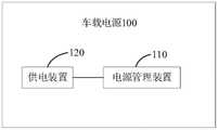
请参阅图3,为本公开实施例提供的一种车载电源的结构示意图。如图3所示,该车载电源100包括电源管理装置110以及供电装置120。电源管理装置110与供电装置120电性连接。其中,电源管理装置110用于转换供电装置120输出的电源信号为各类负载供电。其中,该各类负载可以是前述的自动驾驶系统200中的传感器模块和/或组合导航模块中的各个部件。Please refer to FIG. 3 , which is a schematic structural diagram of an in-vehicle power supply according to an embodiment of the present disclosure. As shown in FIG. 3 , the
具体地,供电装置120可以是自动驾驶车辆上的车载蓄电池,也即电瓶,通常供电装置120输出的电源信号为12V,而不同类型的负载所需要的电压信号不同,因此需要将供电装置120输出的电压信号经过电源管理装置110进行转换后,才能输出给不同类型的负载进行供电。Specifically, the
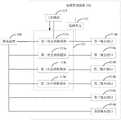
请参阅图4,为本公开实施例提供的第一种电源管理装置的原理框图。如图4所示,该电源管理装置110包括选择单元111、主控模块112以及多个电压转换模块113。其中,选择单元111分别与主控模块112以及多个电压转换模块113中的目标电压转换模块113a连接,用于接收车辆启动信号,并根据所述车辆启动信号控制所述目标电压转换模块113a上电工作,进而为主控模块112提供工作电压,使得主控模块112上电工作。Please refer to FIG. 4 , which is a schematic block diagram of a first power management apparatus provided by an embodiment of the present disclosure. As shown in FIG. 4 , the
示例性地,选择单元111包括或门。Illustratively, the
具体地,电压转换模块113用于将供电装置120输出的电源信号进行转换,以为不同类型的负载进行供电。Specifically, the
所述主控模块112还分别与除所述目标电压转换模块113a之外的其他电压转换模块113连接,所述主控模块112上电工作后,用于控制所述其他电压转换模块113按照预设的上电时序依次上电工作。The
具体地,主控模块112可以为微控制单元,也即处理器。该处理器可能是一种集成电路芯片,具有信号的处理能力。前述的处理器可以是通用处理器,包括中央处理器(Central Processing Unit,CPU)、网络处理器(Network Processor,NP)等;还可以是数字信号处理器(DSP)、专用集成电路(ASIC)、现场可编程门阵列(FPGA)或者其他可编程逻辑器件、分立门或者晶体管逻辑器件、分立硬件组件等。Specifically, the
本公开实施例中,选择单元分别与主控模块以及目标电压转换模块连接,用于接收车辆启动信号,并根据车辆启动信号控制目标电压转换模块上电工作,进而为主控模块提供工作电压,使得主控模块上电工作,同时主控模块可以控制其他电压转换模块按照预设的上电时序依次上电工作,如此,可以进一步使得各类负载能够有序上电,进而能够减少因上电时序错乱而引发的系统供电故障问题发生的频率。In the embodiment of the present disclosure, the selection unit is respectively connected to the main control module and the target voltage conversion module, and is used to receive the vehicle start signal, and control the target voltage conversion module to work according to the vehicle start signal, so as to provide the main control module with a working voltage, The main control module is powered on to work, and at the same time, the main control module can control other voltage conversion modules to be powered on and work in sequence according to the preset power-on sequence. In this way, various loads can be powered on in an orderly manner, thereby reducing power-on problems. The frequency of system power failure problems caused by timing disorder.
在一种可能的实施方式中,参见图5所示,为本公开实施例提供的第二种电源管理装置的原理框图。如图5所示,所述多个电压转换模块113包括至少一个第一电压转换模块113a以及至少一个第二电压转换模块113b,所述目标电压转换模块113a为所述至少一个第一电压转换模块113a中的电压转换模块。其中,至少一个第一电压转换模块113b,分别与所述供电装置120连接,每个第一电压转换模块113b用于将所述电源信号转换成第一电压信号以为第一类型的负载供电。In a possible implementation manner, referring to FIG. 5 , it is a schematic block diagram of a second power management apparatus provided by an embodiment of the present disclosure. As shown in FIG. 5 , the plurality of
具体地,至少一个第二电压转换模块113b,分别与所述供电装置120连接,每个第二电压转换模块113b用于将所述电源信号转换成第二电压信号以为第二类型的负载供电。本实施方式中,示意出了两个,在其他实施方式中,可以是一个还可以是更多。如此,可以实现不同负载的不同供电需求,以使得每个负载都能正常工作。Specifically, at least one second
在一些实施方式中,第一电压信号小于第二电压信号,比如,第一电压信号对应的电压可以为5V稳压电源,第一类型的负载可以是通用的电子设备,比如手机,使用第一接口(USB接口)对电子设备进行供电,还可以是主控模块,通常为单片机,还可以是显示屏,此处不作限定。第二电压信号对应的电压可以为12V稳压电源。第二类型的负载可以是前述的自动驾驶系统200中的传感器模块中的激光雷达、毫米波雷达等,还可以是前述的自动驾驶系统200中的组合导航模块中的全球导航卫星系统、惯性传感器等,还可以是前述的自动驾驶系统200中的车载单元。In some embodiments, the first voltage signal is smaller than the second voltage signal. For example, the voltage corresponding to the first voltage signal may be a 5V regulated power supply, and the first type of load may be a general electronic device, such as a mobile phone, using the first The interface (USB interface) supplies power to the electronic device, and can also be a main control module, usually a single-chip microcomputer, or a display screen, which is not limited here. The voltage corresponding to the second voltage signal may be a 12V regulated power supply. The second type of load may be the aforementioned lidar, millimeter-wave radar, etc. in the sensor module in the automatic driving system 200 , and may also be the global navigation satellite system and inertial sensor in the aforementioned integrated navigation module in the automatic driving system 200 . etc., it may also be the vehicle-mounted unit in the aforementioned automatic driving system 200 .
示例性地,至少一个第一电压转换模块113b.1可以采用同步Buck电路实现;至少一个第二电压转换模块113b.2可以采用四开关Buck-Boost电路拓扑,进而实现宽输入电压、大电流高效率的电压转换。Exemplarily, the at least one first voltage conversion module 113b.1 may be implemented by a synchronous Buck circuit; the at least one second voltage conversion module 113b.2 may be implemented by a four-switch Buck-Boost circuit topology, thereby realizing wide input voltage, high current and high current. Efficient voltage conversion.
在一种可能的实施方式中,请再次参见图5所示,所述电源管理装置还包括至少一个第一输出接口114a以及至少一个第二输出接口114b。其中,至少一个第一输出接口114a与至少一个第一电压转换模块113a电性连接,用于将第一电压信号输出,以为第一类型的负载供电。至少一个第二输出接口114b与至少一个第二电压转换模块113b电性连接,用于将所述第二电压信号输出,以为第二类型的负载供电。In a possible implementation manner, referring to FIG. 5 again, the power management apparatus further includes at least one
具体地,至少一个第一输出接口114a的数量与至少一个第一电压转换模块113a的数量相同且一一对应,至少一个第二输出接口114b的数量与至少一个第二电压转换模块113b的数量相同且一一对应。本实施方式中,所述至少一个第一电压转换模块113a、所述至少一个第二电压转换模块113b、所述至少一个第一输出接口114a以及所述至少一个第二输出接口114b集成于同一印制电路板。如此,可以使得电源管理装置形成能够多路输出的电源,为不同类型的负载进行供电,简化了供电设备的布线需求,有利于电源的管理,从而使得供电线路更加美观。Specifically, the number of at least one
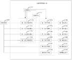
请参阅图6,为本公开实施例提供的第三种电源管理装置的结构示意图。如图6所示,该电源管理装置110还包括第三输出接口114c以及第四输出接口114d。所述第三输出接口114c与供电装置120电性连接,用于将所述电源信号输出,以为第三类型的负载供电,所述第三类型的负载可以是12V非稳压电源需求的设备,比如,充气阀。所述第四输出接口114d与供电装置120电性连接,用于将所述电源信号输出,以为第四类型的负载供电,所述第四类型的负载可以是12V大电流输出需求的设备,可以是工控机,也即车载计算机。Please refer to FIG. 6 , which is a schematic structural diagram of a third power management apparatus according to an embodiment of the present disclosure. As shown in FIG. 6 , the
在一种可能的实施方式中,请参阅图7,为本公开实施例提供的第四种电源管理装置的结构示意图。如图7所示,该电源管理装置110还包括至少一个第一保护模块115a以及至少一个第二保护模块115b。所述至少一个第一保护模块115a,分别与所述至少一个第一电压转换模块113a以及所述至少一个第一输出接口114a一一对应,每个所述第一保护模块115a连接于对应的所述第一电压转换模块111a以及对应的所述第一输出接口模块114a之间,用于检测其所在回路的第一状态信息,所述第一状态信息包括第一保护模块115a所在回路的电压信息、电流信息、温度信息等。其中,第一保护模块115a所在回路由供电装置120、第一电压转换模块113a、第一保护模块115a、第一输出接口114a以及与第一输出接口114a连接的第一类型负载构成。In a possible implementation manner, please refer to FIG. 7 , which is a schematic structural diagram of a fourth power management apparatus according to an embodiment of the present disclosure. As shown in FIG. 7 , the
所述至少一个第二保护模块115b,分别与所述至少一个第二电压转换模块113b以及所述至少一个第二输出接口114b一一对应,每个所述第二保护模块115b连接于对应的所述第二电压转换模块113b以及对应的所述第二输出接口模块114b之间,用于检测其所在回路的第二状态信息,所述第二状态信息包括第二保护模块115b所在回路的电压信息、电流信息、温度信息等。类似地,第二保护模块115b所在回路由供电装置120、第二电压转换模块113b、第二保护模块115b、第二输出接口114b以及与第二输出接口114b连接的第二类型负载构成。The at least one
示例性地,该第一保护模块115a以及第二保护模块115b可以包括电子保险丝(E-fuse)或者热插拔控制器芯片。Exemplarily, the
示例性地,所述主控模块112分别与所述第一保护模块115a以及所述第二保护模块115b相连,用于接收所述第一状态信息以及所述第二状态信息;针对每个回路,所述主控模块112还用于在所述第一状态信息异常时,控制所述第一保护模块115a断开所述第一电压转换模块113a与所述第一输出接口114a之间的电性连接,如此,可以为第一保护模块115a所在回路提供过压保护、欠压保护、过流保护以及过温保护。所述主控模块112还用于在所述第二状态信息异常时,控制所述第二保护模块115b断开所述第二电压转换模块113b与所述第二输出接口114b之间的电性连接。如此,可以为第二保护模块115b所在的回路提供过压保护、欠压保护、过流保护以及过温保护。Exemplarily, the
在另一些实施方式中,所述主控模块112还用于针对所述每个回路,在所述第一状态信息恢复为正常状态时,控制所述第一保护模块115a建立所述第一电压转换模块113a与所述第一输出接口114a之间的电性连接,或者,在所述第二状态信息恢复为正常状态时,控制所述第二保护模块115b建立所述第二电压转换模块113b与所述第二输出接口114b之间的电性连接。如此,可以提供自动恢复的保护功能,避免手动更换保险丝。In other embodiments, the
在一种可能的实施方式中,请参阅图8,为本公开实施例提供的第五种电源管理装置的结构示意图。如图8所示,该电源管理装置110还包括第三保护模块115c以及第四保护模块115d。所述第三保护模块115c连接于供电装置120以及第三输出接口114c之间,用于检测其所在回路的第三状态信息,所述第三状态信息包括第三保护模块115c所在回路的电压信息、电流信息、温度信息等。类似地,第三保护模块115c所在回路由供电装置120、第三保护模块115c、第三输出接口114c以及第三输出接口114c连接的第三类型负载构成。In a possible implementation manner, please refer to FIG. 8 , which is a schematic structural diagram of a fifth power management apparatus according to an embodiment of the present disclosure. As shown in FIG. 8 , the
其中,所述第四保护模块115d连接于供电装置120以及第四输出接口114d电性之间,用于检测其所在回路的第四状态信息,所述第四状态信息包括第四保护模块115d所在回路的电压信息、电流信息、温度信息等。类似地,第四保护模块115d所在回路由供电装置120、第四保护模块115d、第四输出接口114d以及第四输出接口114d连接的第四类型负载构成。Wherein, the
所述主控模块112分别与所述第三保护模块115c以及所述第四保护模块115d相连,用于接收所述第三状态信息以及所述第四状态信息,并在所述第三状态信息异常时,控制所述第三保护模块115c断开所述供电装置120与所述第三输出接口114c之间的电性连接,如此,可以为第三保护模块115c所在回路提供过压保护、欠压保护、过流保护以及过温保护。所述主控模块112还用于在所述第四状态信息异常时,控制所述第四保护模块115d断开所述供电装置120与所述第四输出接口114d之间的电性连接,如此,可以为第四保护模块115d所在回路提供过压保护、欠压保护、过流保护以及过温保护。The
在另一些实施方式中,所述主控模块112还用于在所述第三状态信息恢复为正常状态时,控制所述第三保护模块115c建立所述供电装置120与所述第三输出接口114c之间的电性连接,或者,在所述第四状态信息恢复为正常状态时,控制所述第四保护模块115d建立所述供电装置120与所述第四输出接口114d之间的电性连接。In other embodiments, the
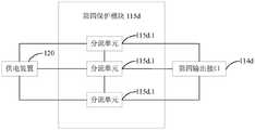
示例性地,参见图9所示,所述第四保护模块115d包括多个分流单元115d.1,所述多个分流单元115d.1并联于所述供电装置120与所述第四输出接口114d之间,用于实现对大电流的输出控制,以使得第四输出接口114d可以对功率较高的负载进行供电。Exemplarily, as shown in FIG. 9 , the
示例性地,每个分流单元115d.1可以是电子保险丝(E-fuse),或者是热插拔控制器芯片,也即采用多个电子保险丝或者热插拔控制器芯片并联,并且完成均流,进而实现大电流的输出控制。Exemplarily, each shunt unit 115d.1 may be an electronic fuse (E-fuse), or a hot-plug controller chip, that is, multiple electronic fuses or hot-plug controller chips are used in parallel, and the current sharing is completed. , and then realize the output control of large current.
类似地,第三保护模块115c也可以包括电子保险丝或者热插拔控制器芯片。具体实用数量可以根据实际需求而定,比如,可以采用一片电子保险丝或者一个热插拔控制器芯片。Similarly, the
在一种可能的实施方式中,请参阅图10,为本公开实施例提供的第五种电源管理装置的结构示意图。如图10所示,该电源管理装置110还包括采集模块116,该采集模块116连接于所述供电装置120以及所述主控模块112之间,用于检测所述供电装置120的供电状态信息,并将检测到的所述供电状态信息发送给所述主控模块112。其中,所述供电状态信息包括供电装置120的供电电压信息、供电电流信息、供电温度信息等。In a possible implementation manner, please refer to FIG. 10 , which is a schematic structural diagram of a fifth power management apparatus according to an embodiment of the present disclosure. As shown in FIG. 10 , the
应注意到:相似的标号和字母在下面的附图中表示类似项,因此,一旦某一项在一个附图中被定义,则在随后的附图中不需要对其进行进一步定义和解释。It should be noted that like numerals and letters refer to like items in the following figures, so once an item is defined in one figure, it does not require further definition and explanation in subsequent figures.
在本公开的描述中,需要说明的是,术语“中心”、“上”、“下”、“左”、“右”、“竖直”、“水平”、“内”、“外”等指示的方位或位置关系为基于附图所示的方位或位置关系,或者是该发明产品使用时惯常摆放的方位或位置关系,仅是为了便于描述本公开和简化描述,而不是指示或暗示所指的自动驾驶系统或元件必须具有特定的方位、以特定的方位构造和操作,因此不能理解为对本公开的限制。此外,术语“第一”、“第二”、“第三”等仅用于区分描述,而不能理解为指示或暗示相对重要性。In the description of the present disclosure, it should be noted that the terms "center", "upper", "lower", "left", "right", "vertical", "horizontal", "inner", "outer", etc. The indicated orientation or positional relationship is based on the orientation or positional relationship shown in the accompanying drawings, or the orientation or positional relationship that the product of the invention is usually placed in use, only for the convenience of describing the present disclosure and simplifying the description, rather than indicating or implying The referenced autonomous driving system or element must have a specific orientation, be constructed and operated in a specific orientation, and therefore should not be construed as a limitation of the present disclosure. Furthermore, the terms "first", "second", "third", etc. are only used to differentiate the description and should not be construed as indicating or implying relative importance.
在本公开的描述中,还需要说明的是,除非另有明确的规定和限定,术语“设置”、“安装”、“相连”、“连接”应做广义理解,例如,可以是固定连接,也可以是可拆卸连接,或一体地连接;可以是机械连接,也可以是电连接;可以是直接相连,也可以通过中间媒介间接相连,可以是两个元件内部的连通。对于本领域的普通技术人员而言,可以具体情况理解上述术语在本公开中的具体含义。In the description of the present disclosure, it should also be noted that, unless otherwise expressly specified and limited, the terms "arranged", "installed", "connected" and "connected" should be understood in a broad sense, for example, it may be a fixed connection, It can also be a detachable connection, or an integral connection; it can be a mechanical connection or an electrical connection; it can be a direct connection, or an indirect connection through an intermediate medium, or the internal communication between the two components. For those of ordinary skill in the art, the specific meanings of the above terms in the present disclosure can be understood in specific situations.
最后应说明的是:以上所述实施例,仅为本公开的具体实施方式,用以说明本公开的技术方案,而非对其限制,本公开的保护范围并不局限于此,尽管参照前述实施例对本公开进行了详细的说明,本领域的普通技术人员应当理解:任何熟悉本技术领域的技术人员在本公开揭露的技术范围内,其依然可以对前述实施例所记载的技术方案进行修改或可轻易想到变化,或者对其中部分技术特征进行等同替换;而这些修改、变化或者替换,并不使相应技术方案的本质脱离本申请实施例技术方案的精神和范围。都应涵盖在本公开的保护范围之内。因此,本公开的保护范围应所述以权利要求的保护范围为准。Finally, it should be noted that the above-mentioned embodiments are only specific implementations of the present disclosure, and are used to illustrate the technical solutions of the present disclosure rather than limit them. The protection scope of the present disclosure is not limited thereto, although referring to the foregoing The embodiments describe the present disclosure in detail. Those of ordinary skill in the art should understand that: any person skilled in the art can still modify the technical solutions described in the foregoing embodiments within the technical scope disclosed by the present disclosure. Changes can be easily conceived, or equivalent replacements are made to some of the technical features; and these modifications, changes or replacements do not make the essence of the corresponding technical solutions deviate from the spirit and scope of the technical solutions in the embodiments of the present application. All should be included within the protection scope of the present disclosure. Therefore, the protection scope of the present disclosure should be based on the protection scope of the claims.
Claims (13)
Translated fromChinesePriority Applications (1)
| Application Number | Priority Date | Filing Date | Title |
|---|---|---|---|
| CN202210614680.0ACN114872649A (en) | 2022-05-31 | 2022-05-31 | Power Management Devices, Vehicle Power Supplies, and Vehicles |
Applications Claiming Priority (1)
| Application Number | Priority Date | Filing Date | Title |
|---|---|---|---|
| CN202210614680.0ACN114872649A (en) | 2022-05-31 | 2022-05-31 | Power Management Devices, Vehicle Power Supplies, and Vehicles |
Publications (1)
| Publication Number | Publication Date |
|---|---|
| CN114872649Atrue CN114872649A (en) | 2022-08-09 |
Family
ID=82679177
Family Applications (1)
| Application Number | Title | Priority Date | Filing Date |
|---|---|---|---|
| CN202210614680.0APendingCN114872649A (en) | 2022-05-31 | 2022-05-31 | Power Management Devices, Vehicle Power Supplies, and Vehicles |
Country Status (1)
| Country | Link |
|---|---|
| CN (1) | CN114872649A (en) |
Cited By (1)
| Publication number | Priority date | Publication date | Assignee | Title |
|---|---|---|---|---|
| CN120056887A (en)* | 2024-08-23 | 2025-05-30 | 北京卡文新能源汽车有限公司 | Power supply device, method and vehicle |
Citations (37)
| Publication number | Priority date | Publication date | Assignee | Title |
|---|---|---|---|---|
| DE10250616C1 (en)* | 2002-10-30 | 2003-11-20 | Siemens Ag | Automobile onboard electrical supply network for control devices, has master control device controlling switching of slave control devices from stand-by mode to normal operating mode |
| US20110025125A1 (en)* | 2009-07-31 | 2011-02-03 | Ladislaus Joseph Brabec | Bi-directional battery voltage converter |
| CN102255342A (en)* | 2010-05-18 | 2011-11-23 | 中国兵器工业第二〇五研究所 | Power manager used by armoured vehicle |
| CN102361332A (en)* | 2011-09-29 | 2012-02-22 | 重庆小康工业集团股份有限公司 | Wake-up device for main power supply |
| CN102420458A (en)* | 2010-09-24 | 2012-04-18 | 三菱电机株式会社 | Power Systems |
| CN203734355U (en)* | 2014-03-21 | 2014-07-23 | 北京经纬恒润科技有限公司 | Vehicle-mounted system |
| CN203770799U (en)* | 2014-03-28 | 2014-08-13 | 青岛歌尔声学科技有限公司 | Power supply time-sequence control circuit and electromagnetic valve control system |
| JP2016037231A (en)* | 2014-08-08 | 2016-03-22 | マツダ株式会社 | Vehicle power supply controller |
| CN105717841A (en)* | 2016-03-21 | 2016-06-29 | 广州橙行智动汽车科技有限公司 | Power supply circuit of electric automobile central control system and implementation method thereof |
| CN107054258A (en)* | 2015-12-03 | 2017-08-18 | 福特全球技术公司 | Distributed using the vehicle electrical power of the relay with integrated electric pressure converter |
| CN107472171A (en)* | 2017-07-04 | 2017-12-15 | 北汽福田汽车股份有限公司 | Power supply management device, method and vehicle |
| CN107681707A (en)* | 2016-10-17 | 2018-02-09 | 深圳市东方之星电源有限公司 | A kind of automobile and automobile power supply system dormancy control circuit |
| CN207166170U (en)* | 2017-08-10 | 2018-03-30 | 中山市远大科技有限公司 | A vehicle charging manager |
| CN107878364A (en)* | 2017-01-25 | 2018-04-06 | 问众智能信息科技(北京)有限公司 | A kind of Optimal Control System and control method of automobile power source change-over circuit |
| CN108162898A (en)* | 2017-12-26 | 2018-06-15 | 天津天地伟业投资管理有限公司 | Method is delayed to turn off after a kind of mobile unit igniting closing |
| CN108944746A (en)* | 2018-08-31 | 2018-12-07 | 华勤通讯技术有限公司 | A kind of mobile unit and automobile |
| CN109407648A (en)* | 2018-08-30 | 2019-03-01 | 深圳市易成自动驾驶技术有限公司 | Troubleshooting methodology, system and computer readable storage medium in power up |
| JP2019103323A (en)* | 2017-12-06 | 2019-06-24 | トヨタ自動車株式会社 | Power supply system |
| CN110884450A (en)* | 2019-11-25 | 2020-03-17 | 珠海格力电器股份有限公司 | Power supply control circuit and electric automobile |
| CN211089223U (en)* | 2019-12-25 | 2020-07-24 | 深圳市诺威达科技有限公司 | Vehicle navigation MCU power supply circuit capable of improving power-on stability |
| CN111930040A (en)* | 2020-08-04 | 2020-11-13 | 湖北亿咖通科技有限公司 | Control device and method for vehicle-mounted central control display screen |
| US20200377044A1 (en)* | 2019-05-28 | 2020-12-03 | Mazda Motor Corporation | Power control device for vehicle |
| CN112087034A (en)* | 2020-09-14 | 2020-12-15 | 广东高标电子科技有限公司 | Electric vehicle power-on and power-off control method and circuit and electric vehicle |
| CN212243231U (en)* | 2020-08-04 | 2020-12-29 | 湖北亿咖通科技有限公司 | Control device of vehicle-mounted central control display screen, vehicle-mounted information entertainment system and vehicle |
| CN112243556A (en)* | 2018-06-11 | 2021-01-19 | 沃尔沃卡车集团 | DC/DC converter overload management in vehicle electrical systems |
| CN112277851A (en)* | 2020-10-30 | 2021-01-29 | 东风商用车有限公司 | Vehicle multi-energy management 48V power-on and power-off control method and system |
| CN212796765U (en)* | 2020-06-05 | 2021-03-26 | 湖北亿咖通科技有限公司 | Vehicle-mounted power consumption control device, vehicle-mounted information entertainment system and vehicle |
| CN212873573U (en)* | 2020-05-21 | 2021-04-02 | 北京万集科技股份有限公司 | Power supply control circuit of vehicle-mounted electronic unit, vehicle-mounted electronic unit and ETC system |
| CN113085551A (en)* | 2021-05-14 | 2021-07-09 | 潍柴动力股份有限公司 | Power management system for whole vehicle system and motor controller |
| CN113126545A (en)* | 2021-04-15 | 2021-07-16 | 南京兆岳智能科技有限公司 | Power management system, method and apparatus for autonomous vehicle controller |
| CN113119732A (en)* | 2021-05-17 | 2021-07-16 | 合肥阳光电动力科技有限公司 | Power supply control method and system and new energy automobile |
| CN113799716A (en)* | 2020-06-12 | 2021-12-17 | 广州汽车集团股份有限公司 | SOC power supply system and monitoring method based on SOC power supply system |
| CN215378758U (en)* | 2021-01-14 | 2021-12-31 | 深圳市兆驰数码科技股份有限公司 | Power-on sequence control system |
| CN113859047A (en)* | 2020-06-30 | 2021-12-31 | 宁德时代新能源科技股份有限公司 | Low-voltage power transmission system, DCDC converter, control method, equipment and medium |
| CN113937985A (en)* | 2021-11-24 | 2022-01-14 | 北京百度网讯科技有限公司 | Power supply control system and vehicle |
| CN114077018A (en)* | 2020-08-17 | 2022-02-22 | 广东海信宽带科技有限公司 | Optical module |
| CN219980435U (en)* | 2022-12-29 | 2023-11-07 | 兆讯恒达科技股份有限公司 | Chip sequential power-on time sequence control circuit |
- 2022
- 2022-05-31CNCN202210614680.0Apatent/CN114872649A/enactivePending
Patent Citations (37)
| Publication number | Priority date | Publication date | Assignee | Title |
|---|---|---|---|---|
| DE10250616C1 (en)* | 2002-10-30 | 2003-11-20 | Siemens Ag | Automobile onboard electrical supply network for control devices, has master control device controlling switching of slave control devices from stand-by mode to normal operating mode |
| US20110025125A1 (en)* | 2009-07-31 | 2011-02-03 | Ladislaus Joseph Brabec | Bi-directional battery voltage converter |
| CN102255342A (en)* | 2010-05-18 | 2011-11-23 | 中国兵器工业第二〇五研究所 | Power manager used by armoured vehicle |
| CN102420458A (en)* | 2010-09-24 | 2012-04-18 | 三菱电机株式会社 | Power Systems |
| CN102361332A (en)* | 2011-09-29 | 2012-02-22 | 重庆小康工业集团股份有限公司 | Wake-up device for main power supply |
| CN203734355U (en)* | 2014-03-21 | 2014-07-23 | 北京经纬恒润科技有限公司 | Vehicle-mounted system |
| CN203770799U (en)* | 2014-03-28 | 2014-08-13 | 青岛歌尔声学科技有限公司 | Power supply time-sequence control circuit and electromagnetic valve control system |
| JP2016037231A (en)* | 2014-08-08 | 2016-03-22 | マツダ株式会社 | Vehicle power supply controller |
| CN107054258A (en)* | 2015-12-03 | 2017-08-18 | 福特全球技术公司 | Distributed using the vehicle electrical power of the relay with integrated electric pressure converter |
| CN105717841A (en)* | 2016-03-21 | 2016-06-29 | 广州橙行智动汽车科技有限公司 | Power supply circuit of electric automobile central control system and implementation method thereof |
| CN107681707A (en)* | 2016-10-17 | 2018-02-09 | 深圳市东方之星电源有限公司 | A kind of automobile and automobile power supply system dormancy control circuit |
| CN107878364A (en)* | 2017-01-25 | 2018-04-06 | 问众智能信息科技(北京)有限公司 | A kind of Optimal Control System and control method of automobile power source change-over circuit |
| CN107472171A (en)* | 2017-07-04 | 2017-12-15 | 北汽福田汽车股份有限公司 | Power supply management device, method and vehicle |
| CN207166170U (en)* | 2017-08-10 | 2018-03-30 | 中山市远大科技有限公司 | A vehicle charging manager |
| JP2019103323A (en)* | 2017-12-06 | 2019-06-24 | トヨタ自動車株式会社 | Power supply system |
| CN108162898A (en)* | 2017-12-26 | 2018-06-15 | 天津天地伟业投资管理有限公司 | Method is delayed to turn off after a kind of mobile unit igniting closing |
| CN112243556A (en)* | 2018-06-11 | 2021-01-19 | 沃尔沃卡车集团 | DC/DC converter overload management in vehicle electrical systems |
| CN109407648A (en)* | 2018-08-30 | 2019-03-01 | 深圳市易成自动驾驶技术有限公司 | Troubleshooting methodology, system and computer readable storage medium in power up |
| CN108944746A (en)* | 2018-08-31 | 2018-12-07 | 华勤通讯技术有限公司 | A kind of mobile unit and automobile |
| US20200377044A1 (en)* | 2019-05-28 | 2020-12-03 | Mazda Motor Corporation | Power control device for vehicle |
| CN110884450A (en)* | 2019-11-25 | 2020-03-17 | 珠海格力电器股份有限公司 | Power supply control circuit and electric automobile |
| CN211089223U (en)* | 2019-12-25 | 2020-07-24 | 深圳市诺威达科技有限公司 | Vehicle navigation MCU power supply circuit capable of improving power-on stability |
| CN212873573U (en)* | 2020-05-21 | 2021-04-02 | 北京万集科技股份有限公司 | Power supply control circuit of vehicle-mounted electronic unit, vehicle-mounted electronic unit and ETC system |
| CN212796765U (en)* | 2020-06-05 | 2021-03-26 | 湖北亿咖通科技有限公司 | Vehicle-mounted power consumption control device, vehicle-mounted information entertainment system and vehicle |
| CN113799716A (en)* | 2020-06-12 | 2021-12-17 | 广州汽车集团股份有限公司 | SOC power supply system and monitoring method based on SOC power supply system |
| CN113859047A (en)* | 2020-06-30 | 2021-12-31 | 宁德时代新能源科技股份有限公司 | Low-voltage power transmission system, DCDC converter, control method, equipment and medium |
| CN212243231U (en)* | 2020-08-04 | 2020-12-29 | 湖北亿咖通科技有限公司 | Control device of vehicle-mounted central control display screen, vehicle-mounted information entertainment system and vehicle |
| CN111930040A (en)* | 2020-08-04 | 2020-11-13 | 湖北亿咖通科技有限公司 | Control device and method for vehicle-mounted central control display screen |
| CN114077018A (en)* | 2020-08-17 | 2022-02-22 | 广东海信宽带科技有限公司 | Optical module |
| CN112087034A (en)* | 2020-09-14 | 2020-12-15 | 广东高标电子科技有限公司 | Electric vehicle power-on and power-off control method and circuit and electric vehicle |
| CN112277851A (en)* | 2020-10-30 | 2021-01-29 | 东风商用车有限公司 | Vehicle multi-energy management 48V power-on and power-off control method and system |
| CN215378758U (en)* | 2021-01-14 | 2021-12-31 | 深圳市兆驰数码科技股份有限公司 | Power-on sequence control system |
| CN113126545A (en)* | 2021-04-15 | 2021-07-16 | 南京兆岳智能科技有限公司 | Power management system, method and apparatus for autonomous vehicle controller |
| CN113085551A (en)* | 2021-05-14 | 2021-07-09 | 潍柴动力股份有限公司 | Power management system for whole vehicle system and motor controller |
| CN113119732A (en)* | 2021-05-17 | 2021-07-16 | 合肥阳光电动力科技有限公司 | Power supply control method and system and new energy automobile |
| CN113937985A (en)* | 2021-11-24 | 2022-01-14 | 北京百度网讯科技有限公司 | Power supply control system and vehicle |
| CN219980435U (en)* | 2022-12-29 | 2023-11-07 | 兆讯恒达科技股份有限公司 | Chip sequential power-on time sequence control circuit |
Cited By (1)
| Publication number | Priority date | Publication date | Assignee | Title |
|---|---|---|---|---|
| CN120056887A (en)* | 2024-08-23 | 2025-05-30 | 北京卡文新能源汽车有限公司 | Power supply device, method and vehicle |
Similar Documents
| Publication | Publication Date | Title |
|---|---|---|
| CN112622928B (en) | Automatic driving system and vehicle | |
| US20220080990A1 (en) | Redundant Hardware System For Autonomous Vehicles | |
| CN108170126B (en) | Control system and automobile | |
| US9829886B2 (en) | Flight control system, a circuit board assembly and a configuration method thereof | |
| US20230106791A1 (en) | Control device for vehicle and automatic driving system | |
| CN108995537B (en) | A whole car controlling means for vehicle intelligence is driven | |
| US11807259B2 (en) | Hardware systems for an autonomous vehicle | |
| CN210391112U (en) | Self-driving vehicles and systems for self-driving vehicles | |
| JP2022126594A (en) | Data transmission device and system | |
| US11912291B2 (en) | Autonomous vehicle and system for autonomous vehicle | |
| US12060081B2 (en) | Integrated module for sensor data aggregation and control of sensor support hardware | |
| US11758392B1 (en) | Electronic tag device | |
| CN114872649A (en) | Power Management Devices, Vehicle Power Supplies, and Vehicles | |
| KR101703500B1 (en) | Vehicle unit | |
| CN211015932U (en) | A road traffic accident early warning system | |
| CN220708749U (en) | Equipment test system for test vehicle and test vehicle thereof | |
| CN205070985U (en) | Vehicle -mounted terminal | |
| CN220323755U (en) | Controller suitable for high-altitude unmanned mining card | |
| CN211856901U (en) | Miniature intelligent vehicle and intelligent networking system with same | |
| CN206171448U (en) | Speed limiting device based on driving habits | |
| CN106652538A (en) | Intelligent electronic bus-stop board control system | |
| CN111190187A (en) | Miniature intelligent vehicle and intelligent networking system with same | |
| CN221446666U (en) | A roadside equipment in a mining area | |
| US20250083689A1 (en) | Hardware systems for an autonomous vehicle | |
| CN215773580U (en) | A vehicle positioning module and electronic device |
Legal Events
| Date | Code | Title | Description |
|---|---|---|---|
| PB01 | Publication | ||
| PB01 | Publication | ||
| SE01 | Entry into force of request for substantive examination | ||
| SE01 | Entry into force of request for substantive examination |