CN114870242A - Blood pump and its driving device - Google Patents
Blood pump and its driving deviceDownload PDFInfo
- Publication number
- CN114870242A CN114870242ACN202210169758.2ACN202210169758ACN114870242ACN 114870242 ACN114870242 ACN 114870242ACN 202210169758 ACN202210169758 ACN 202210169758ACN 114870242 ACN114870242 ACN 114870242A
- Authority
- CN
- China
- Prior art keywords
- shaft
- driving
- magnet
- rotor
- stator
- Prior art date
- Legal status (The legal status is an assumption and is not a legal conclusion. Google has not performed a legal analysis and makes no representation as to the accuracy of the status listed.)
- Pending
Links
- 210000004369bloodAnatomy0.000titleclaimsabstractdescription38
- 239000008280bloodSubstances0.000titleclaimsabstractdescription38
- 230000007246mechanismEffects0.000claimsabstractdescription18
- 238000004891communicationMethods0.000claimsdescription27
- 239000012530fluidSubstances0.000claimsdescription27
- 230000004087circulationEffects0.000claimsdescription5
- 238000004140cleaningMethods0.000description13
- 239000003292glueSubstances0.000description13
- 238000009434installationMethods0.000description13
- 230000005415magnetizationEffects0.000description11
- 238000010586diagramMethods0.000description8
- 239000000243solutionSubstances0.000description7
- 230000004907fluxEffects0.000description5
- 239000000463materialSubstances0.000description5
- 230000009286beneficial effectEffects0.000description4
- 230000020169heat generationEffects0.000description3
- 238000004519manufacturing processMethods0.000description3
- 238000000034methodMethods0.000description3
- 230000002093peripheral effectEffects0.000description3
- MCMNRKCIXSYSNV-UHFFFAOYSA-NZirconium dioxideChemical compoundO=[Zr]=OMCMNRKCIXSYSNV-UHFFFAOYSA-N0.000description2
- 239000000853adhesiveSubstances0.000description2
- 230000001070adhesive effectEffects0.000description2
- 210000004204blood vesselAnatomy0.000description2
- 230000008878couplingEffects0.000description2
- 238000010168coupling processMethods0.000description2
- 238000005859coupling reactionMethods0.000description2
- 239000002504physiological saline solutionSubstances0.000description2
- 230000008569processEffects0.000description2
- 238000007789sealingMethods0.000description2
- 230000002861ventricularEffects0.000description2
- WQZGKKKJIJFFOK-GASJEMHNSA-NGlucoseNatural productsOC[C@H]1OC(O)[C@H](O)[C@@H](O)[C@@H]1OWQZGKKKJIJFFOK-GASJEMHNSA-N0.000description1
- HTTJABKRGRZYRN-UHFFFAOYSA-NHeparinChemical compoundOC1C(NC(=O)C)C(O)OC(COS(O)(=O)=O)C1OC1C(OS(O)(=O)=O)C(O)C(OC2C(C(OS(O)(=O)=O)C(OC3C(C(O)C(O)C(O3)C(O)=O)OS(O)(=O)=O)C(CO)O2)NS(O)(=O)=O)C(C(O)=O)O1HTTJABKRGRZYRN-UHFFFAOYSA-N0.000description1
- 239000004677NylonSubstances0.000description1
- 239000004952PolyamideSubstances0.000description1
- 229920002614Polyether block amidePolymers0.000description1
- 239000004698PolyethyleneSubstances0.000description1
- 239000004721Polyphenylene oxideSubstances0.000description1
- VYPSYNLAJGMNEJ-UHFFFAOYSA-NSilicium dioxideChemical compoundO=[Si]=OVYPSYNLAJGMNEJ-UHFFFAOYSA-N0.000description1
- 229910000831SteelInorganic materials0.000description1
- HZEWFHLRYVTOIW-UHFFFAOYSA-N[Ti].[Ni]Chemical compound[Ti].[Ni]HZEWFHLRYVTOIW-UHFFFAOYSA-N0.000description1
- 238000004026adhesive bondingMethods0.000description1
- PNEYBMLMFCGWSK-UHFFFAOYSA-Naluminium oxideInorganic materials[O-2].[O-2].[O-2].[Al+3].[Al+3]PNEYBMLMFCGWSK-UHFFFAOYSA-N0.000description1
- 210000000709aortaAnatomy0.000description1
- 210000001765aortic valveAnatomy0.000description1
- 238000011001backwashingMethods0.000description1
- WQZGKKKJIJFFOK-VFUOTHLCSA-Nbeta-D-glucoseChemical compoundOC[C@H]1O[C@@H](O)[C@H](O)[C@@H](O)[C@@H]1OWQZGKKKJIJFFOK-VFUOTHLCSA-N0.000description1
- 230000017531blood circulationEffects0.000description1
- 239000000919ceramicSubstances0.000description1
- 239000010941cobaltSubstances0.000description1
- 229910017052cobaltInorganic materials0.000description1
- GUTLYIVDDKVIGB-UHFFFAOYSA-Ncobalt atomChemical compound[Co]GUTLYIVDDKVIGB-UHFFFAOYSA-N0.000description1
- 230000007423decreaseEffects0.000description1
- 230000000694effectsEffects0.000description1
- 210000003743erythrocyteAnatomy0.000description1
- 239000008103glucoseSubstances0.000description1
- 210000005003heart tissueAnatomy0.000description1
- 210000003709heart valveAnatomy0.000description1
- 229960002897heparinDrugs0.000description1
- 229920000669heparinPolymers0.000description1
- 239000012774insulation materialSubstances0.000description1
- 239000004816latexSubstances0.000description1
- 229920000126latexPolymers0.000description1
- 238000005461lubricationMethods0.000description1
- 239000000696magnetic materialSubstances0.000description1
- 238000012986modificationMethods0.000description1
- 230000004048modificationEffects0.000description1
- 229910001000nickel titaniumInorganic materials0.000description1
- 229920001778nylonPolymers0.000description1
- 230000000149penetrating effectEffects0.000description1
- 229920002647polyamidePolymers0.000description1
- 229920000570polyetherPolymers0.000description1
- -1polyethylenePolymers0.000description1
- 229920000573polyethylenePolymers0.000description1
- 229920002635polyurethanePolymers0.000description1
- 239000004814polyurethaneSubstances0.000description1
- 238000005086pumpingMethods0.000description1
- 230000009467reductionEffects0.000description1
- 239000000741silica gelSubstances0.000description1
- 229910002027silica gelInorganic materials0.000description1
- 229910001220stainless steelInorganic materials0.000description1
- 239000010935stainless steelSubstances0.000description1
- 239000010959steelSubstances0.000description1
- 238000003466weldingMethods0.000description1
- 238000004804windingMethods0.000description1
Images


Classifications
- A—HUMAN NECESSITIES
- A61—MEDICAL OR VETERINARY SCIENCE; HYGIENE
- A61M—DEVICES FOR INTRODUCING MEDIA INTO, OR ONTO, THE BODY; DEVICES FOR TRANSDUCING BODY MEDIA OR FOR TAKING MEDIA FROM THE BODY; DEVICES FOR PRODUCING OR ENDING SLEEP OR STUPOR
- A61M60/00—Blood pumps; Devices for mechanical circulatory actuation; Balloon pumps for circulatory assistance
- A61M60/40—Details relating to driving
- A61M60/403—Details relating to driving for non-positive displacement blood pumps
- A61M60/422—Details relating to driving for non-positive displacement blood pumps the force acting on the blood contacting member being electromagnetic, e.g. using canned motor pumps
- A—HUMAN NECESSITIES
- A61—MEDICAL OR VETERINARY SCIENCE; HYGIENE
- A61M—DEVICES FOR INTRODUCING MEDIA INTO, OR ONTO, THE BODY; DEVICES FOR TRANSDUCING BODY MEDIA OR FOR TAKING MEDIA FROM THE BODY; DEVICES FOR PRODUCING OR ENDING SLEEP OR STUPOR
- A61M60/00—Blood pumps; Devices for mechanical circulatory actuation; Balloon pumps for circulatory assistance
- A61M60/10—Location thereof with respect to the patient's body
- A61M60/122—Implantable pumps or pumping devices, i.e. the blood being pumped inside the patient's body
- A61M60/165—Implantable pumps or pumping devices, i.e. the blood being pumped inside the patient's body implantable in, on, or around the heart
- A61M60/17—Implantable pumps or pumping devices, i.e. the blood being pumped inside the patient's body implantable in, on, or around the heart inside a ventricle, e.g. intraventricular balloon pumps
- A—HUMAN NECESSITIES
- A61—MEDICAL OR VETERINARY SCIENCE; HYGIENE
- A61M—DEVICES FOR INTRODUCING MEDIA INTO, OR ONTO, THE BODY; DEVICES FOR TRANSDUCING BODY MEDIA OR FOR TAKING MEDIA FROM THE BODY; DEVICES FOR PRODUCING OR ENDING SLEEP OR STUPOR
- A61M60/00—Blood pumps; Devices for mechanical circulatory actuation; Balloon pumps for circulatory assistance
- A61M60/20—Type thereof
- A61M60/205—Non-positive displacement blood pumps
- A61M60/216—Non-positive displacement blood pumps including a rotating member acting on the blood, e.g. impeller
Landscapes
- Health & Medical Sciences (AREA)
- Engineering & Computer Science (AREA)
- Heart & Thoracic Surgery (AREA)
- Cardiology (AREA)
- Biomedical Technology (AREA)
- Anesthesiology (AREA)
- Mechanical Engineering (AREA)
- Hematology (AREA)
- Life Sciences & Earth Sciences (AREA)
- Animal Behavior & Ethology (AREA)
- General Health & Medical Sciences (AREA)
- Public Health (AREA)
- Veterinary Medicine (AREA)
- Structures Of Non-Positive Displacement Pumps (AREA)
Abstract
Description
Translated fromChinese技术领域technical field
本申请涉及医疗器械技术领域,尤其涉及一种血泵及其驱动装置。The present application relates to the technical field of medical devices, and in particular, to a blood pump and a driving device thereof.
背景技术Background technique
血管内血泵,是一种被设计为经皮插入患者的血管中,被探入患者的心脏 中作为左心室辅助设备或右心室辅助设备的装置,血管内血泵也可以被称为心 内血泵。An intravascular blood pump is a device designed to be inserted percutaneously into a patient's blood vessel and probed into the patient's heart as a left ventricular assist device or a right ventricular assist device. An intravascular blood pump may also be referred to as an intracardiac blood pump.
目前的血管内血泵主要包括叶轮及驱动该叶轮旋转的电机,电机工作时产 生旋转磁场,叶轮上设有与该旋转磁场相互作用的磁体,以使叶轮围绕其轴线 旋转,将血液从血泵的血液流入口输送至血液流出口。然而,由于血管内血泵 的体积较小,所以装配难度较大。The current intravascular blood pump mainly includes an impeller and a motor that drives the impeller to rotate. When the motor works, a rotating magnetic field is generated. The impeller is provided with a magnet that interacts with the rotating magnetic field, so that the impeller rotates around its axis, and the blood is pumped from the blood pump. The blood inflow port is transported to the blood outflow port. However, due to the small volume of the intravascular blood pump, assembly is difficult.
发明内容SUMMARY OF THE INVENTION
本申请提供了一种血泵及其驱动装置,可以使得血泵的装配过程更加简单、 方便。The present application provides a blood pump and a driving device thereof, which can make the assembly process of the blood pump simpler and more convenient.
一种驱动装置,能够带动血泵的叶轮转动,包括:A driving device capable of driving an impeller of a blood pump to rotate, comprising:
驱动壳,设有连通口和限位部;The drive shell is provided with a communication port and a limit part;
转子,能够转动地安装于所述驱动壳,所述转子的部分收容于所述驱动壳, 部分延伸至所述驱动壳外、并与所述叶轮固接;a rotor, which is rotatably mounted on the drive casing, a part of the rotor is accommodated in the drive casing, a part of the rotor extends outside the drive casing, and is fixedly connected to the impeller;
定子机构,收容于所述驱动壳内,所述定子机构能够产生驱动所述转子旋 转的旋转磁场;及a stator mechanism, housed in the drive housing, the stator mechanism capable of generating a rotating magnetic field that drives the rotor to rotate; and
轴套组件,包括安装于所述驱动壳的第一轴套和第二轴套,所述第一轴套 和所述第二轴套沿所述转子的旋转轴线设置,所述第一轴套和所述第二轴套中 的一个与所述限位部抵接,所述第二轴套包括环本体及从所述环本体上延伸出 的延伸部,所述延伸部与所述第一轴套抵接,以使所述环本体与所述第一轴套 间隔,其中,所述转子能够转动地穿设于所述第一轴套和所述环本体,所述连 通口能够供所述第一轴套和所述第二轴套穿过。A bushing assembly, comprising a first bushing and a second bushing mounted on the drive housing, the first bushing and the second bushing are arranged along the rotation axis of the rotor, the first bushing and one of the second bushings is in contact with the limiting portion, the second bushing includes a ring body and an extension portion extending from the ring body, and the extension portion is connected to the first The shaft sleeve is abutted, so that the ring body is spaced from the first shaft sleeve, wherein the rotor is rotatably penetrated through the first shaft sleeve and the ring body, and the communication port can be used for all The first bushing and the second bushing pass through.
在其中一个实施例中,所述转子包括:In one embodiment, the rotor includes:
转轴,所述转轴包括轴本体和环设于所述轴本体的限位环,所述轴本体能 够转动地穿设于所述第一轴套和所述环本体,所述轴本体的一端收容于所述驱 动壳,另一端从所述连通口延伸至所述驱动壳外、并与所述叶轮固接,所述限 位环位于所述环本体和所述第一轴套之间,且所述限位环位于所述轴本体和所 述延伸部之间,所述限位环的外径分别大于所述环本体的内径和所述第一轴套 的内径,以在所述轴本体的延伸方向上对所述转轴限位;A rotating shaft, the rotating shaft includes a shaft body and a limit ring arranged around the shaft body, the shaft body is rotatably penetrated through the first shaft sleeve and the ring body, and one end of the shaft body accommodates In the drive housing, the other end extends from the communication port to the outside of the drive housing and is fixedly connected with the impeller, the limiting ring is located between the ring body and the first bushing, and The limiting ring is located between the shaft body and the extension part, and the outer diameter of the limiting ring is respectively larger than the inner diameter of the ring body and the inner diameter of the first bushing, so as to prevent the shaft body Limiting the rotating shaft in the extension direction of ;
磁组件,所述磁组件固接于所述轴本体,其中,所述定子机构能够产生驱 动所述磁组件旋转的旋转磁场,所述磁组件能够带动所述转轴旋转。A magnetic assembly, the magnetic assembly is fixed on the shaft body, wherein the stator mechanism can generate a rotating magnetic field that drives the magnetic assembly to rotate, and the magnetic assembly can drive the rotating shaft to rotate.
在其中一个实施例中,所述延伸部为环形,所述延伸部与所述环本体共轴, 所述延伸部的内径大于所述限位环的外径,所述延伸部和所述限位环之间形成 供流体流通的间隙。In one embodiment, the extension portion is annular, the extension portion is coaxial with the ring body, the inner diameter of the extension portion is larger than the outer diameter of the limiting ring, the extension portion and the limiting ring are A gap for fluid flow is formed between the bit rings.
在其中一个实施例中,所述第一轴套具有第一轴孔,所述第一轴套的朝向 所述限位环的一侧上还开设有第一导流槽,所述第一导流槽与所述第一轴孔连 通,所述轴本体能够转动地穿设于所述第一轴孔,所述轴本体与所述第一轴孔 之间具有供流体流通的间隙;In one embodiment, the first shaft sleeve has a first shaft hole, a first guide groove is further opened on the side of the first shaft sleeve facing the limit ring, and the first guide groove is The flow groove is communicated with the first shaft hole, the shaft body is rotatably penetrated through the first shaft hole, and there is a gap for fluid circulation between the shaft body and the first shaft hole;
及/或,所述环本体具有第二轴孔,所述环本体的朝向所述限位环的一侧上 还开设有第二导流槽,所述第二导流槽与所述第二轴孔连通,所述轴本体能够 转动地穿设于所述第二轴孔,所述轴本体与所述第二轴孔之间具有供流体流通 的间隙。And/or, the ring body has a second shaft hole, and the side of the ring body facing the limit ring is also provided with a second guide groove, and the second guide groove is connected to the second guide groove. The shaft holes are communicated with each other, the shaft body is rotatably penetrated through the second shaft hole, and there is a gap for fluid circulation between the shaft body and the second shaft hole.
在其中一个实施例中,所述限位环具有外环面及与所述外环面连接的两端 面,所述外环面和所述两端面的连接处均设有倒角。In one of the embodiments, the limiting ring has an outer annular surface and two end surfaces connected to the outer annular surface, and the connection between the outer annular surface and the two end surfaces is provided with a chamfer.
在其中一个实施例中,所述第一轴套上开设有定位槽,所述延伸部的远离 所述环本体的一端收容于所述定位槽中,以对所述第二轴套定位。In one embodiment, a positioning groove is formed on the first bushing, and one end of the extension portion away from the ring body is received in the positioning groove to position the second bushing.
在其中一个实施例中,所述第一轴套包括盘部及形成在所述盘部的一表面 的圆台部,所述第一轴套具有第一轴孔,所述第一轴孔从所述盘部的远离所述 圆台部的表面延伸至所述圆台部的远离所述盘部的一端的端面;所述延伸部为 环形,所述延伸部与所述环本体共轴,所述延伸部套设于所述圆台部上,所述 延伸部的远离所述环本体的一端的端面与所述盘部抵接,其中,所述转子能够 转动地穿设于所述第一轴孔。In one embodiment, the first bushing includes a disc portion and a circular frustum portion formed on a surface of the disc portion, the first bushing has a first shaft hole, and the first shaft hole extends from the The surface of the disc portion away from the circular truncated portion extends to the end face of the end of the circular truncated portion away from the disc portion; the extension portion is annular, the extension portion is coaxial with the ring body, and the extension The end surface of the extension part away from the ring body is in contact with the disk part, wherein the rotor is rotatably penetrated through the first shaft hole.
在其中一个实施例中,所述第一轴套的靠近所述环本体的一侧的孔径大于 所述第一轴套的背离所述环本体的一侧的孔径;及/或,所述环本体的靠近所述 第二轴套的一侧的孔径大于所述环本体的背离所述环本体的一侧的孔径。In one embodiment, the hole diameter of the side of the first bushing close to the ring body is larger than the hole diameter of the side of the first bushing facing away from the ring body; and/or the ring The hole diameter of the side of the body close to the second bushing is larger than the hole diameter of the side of the ring body facing away from the ring body.
在其中一个实施例中,所述第二轴套具有第二轴孔,所述第二轴孔具有直 孔部及与所述直孔部连通的锥形孔部,所述锥形孔部的孔径较小的一端与所述 直孔部连通,孔径较大的一端朝向所述第一轴套,所述转子能够转动地穿设于 所述直孔部和所述锥形孔部。In one embodiment, the second shaft sleeve has a second shaft hole, the second shaft hole has a straight hole portion and a tapered hole portion communicating with the straight hole portion, and the tapered hole portion has a An end with a smaller aperture is communicated with the straight hole portion, an end with a larger aperture faces the first bushing, and the rotor is rotatably penetrated through the straight hole portion and the tapered hole portion.
在其中一个实施例中,所述直孔部在所述转子的旋转轴线方向上的长度大 于或等于0.5毫米。In one of the embodiments, the length of the straight hole portion in the direction of the rotation axis of the rotor is greater than or equal to 0.5 mm.
在其中一个实施例中,所述驱动壳包括壳本体及与所述壳本体对接的安装 壳,所述第一轴套和所述第二轴套均安装于所述安装壳,所述定子机构收容于 所述壳本体,所述连通口和所述限位部均设置于所述安装壳。In one embodiment, the drive casing includes a casing body and a mounting casing that is butted with the casing body, the first bushing and the second bushing are both mounted on the mounting casing, and the stator mechanism It is accommodated in the housing body, and both the communication port and the limiting portion are arranged on the mounting housing.
在其中一个实施例中,所述转子包括转轴和磁组件,所述转轴的一端收容 于所述驱动壳,另一端延伸至所述驱动壳外、并与所述叶轮固接,所述转轴相 对所述驱动壳能够转动,所述磁组件包括第一磁体和第二磁体,所述第一磁体 和所述第二磁体均固接于所述转轴;In one embodiment, the rotor includes a rotating shaft and a magnetic assembly, one end of the rotating shaft is accommodated in the driving casing, and the other end extends outside the driving casing and is fixedly connected to the impeller, and the rotating shaft is opposite to The drive housing can rotate, the magnet assembly includes a first magnet and a second magnet, and the first magnet and the second magnet are both fixed to the rotating shaft;
所述定子机构包括驱动定子和动力定子,所述驱动定子和所述动力定子沿 所述转轴的旋转轴线布置,所述驱动定子能够产生驱动所述第一磁体旋转的旋 转磁场,所述动力定子能够产生驱动所述第二磁体旋转的旋转磁场;其中,所 述第一磁体位于所述驱动定子和所述动力定子之间,其中,所述转轴穿设于所 述动力定子,所述驱动定子在所述转轴的延伸方向上与所述转轴间隔。The stator mechanism includes a driving stator and a power stator, which are arranged along a rotation axis of the rotating shaft, the driving stator capable of generating a rotating magnetic field that drives the rotation of the first magnet, and the power stator. A rotating magnetic field can be generated to drive the second magnet to rotate; wherein, the first magnet is located between the driving stator and the power stator, wherein the rotating shaft passes through the power stator, and the driving stator It is spaced from the rotating shaft in the extending direction of the rotating shaft.
在其中一个实施例中,所述驱动定子包括多个第一磁芯及分别缠绕多个所 述第一磁芯设置的多个第一线圈,多个所述第一磁芯环绕所述转轴的旋转轴线 所在的直线设置一周;所述动力定子包括多个第二磁芯及分别缠绕多个所述第 二磁芯设置的多个第二线圈,多个所述第二磁芯环绕所述转轴设置一周,其中, 所述第一磁芯和所述第二磁芯均包括磁柱,所述第一磁芯的所述磁柱的横截面 积大于所述第二磁芯的所述磁柱的横截面积。In one embodiment, the driving stator includes a plurality of first magnetic cores and a plurality of first coils respectively wound around the plurality of first magnetic cores, and the plurality of first magnetic cores surround the rotating shaft. The straight line where the rotation axis is located is arranged for a circle; the power stator includes a plurality of second magnetic cores and a plurality of second coils respectively wound around the plurality of second magnetic cores, and a plurality of the second magnetic cores surround the rotating shaft The first magnetic core and the second magnetic core both include magnetic pillars, and the cross-sectional area of the magnetic pillars of the first magnetic core is larger than the magnetic pillars of the second magnetic core. cross-sectional area.
在其中一个实施例中,所述转轴具有第一配合段和第二配合段,所述第一 配合段的横截面积大于所述第二配合段的横截面积,所述第一配合段能够转动 地穿设于所述轴套组件,所述第二配合段能够转动地穿设于所述动力定子。In one embodiment, the rotating shaft has a first fitting section and a second fitting section, the cross-sectional area of the first fitting section is larger than the cross-sectional area of the second fitting section, and the first fitting section can The second matching segment is rotatably penetrated through the power stator.
一种血泵,包括:A blood pump that includes:
上述驱动装置;the above-mentioned driving device;
叶轮,设置于所述驱动壳外,所述叶轮与所述转子固接,并且能够随所述 转子旋转。The impeller is arranged outside the drive casing, the impeller is fixedly connected with the rotor, and can rotate with the rotor.
上述血泵的驱动装置用于支撑转子的第一轴套和第二轴套沿转子的旋转轴 线设置,且第一轴套和第二轴套中的一个与驱动壳的限位件抵接,以支撑第一 轴套和第二轴套中的一个,第二轴套的支撑转子的环本体通过第二轴承的延伸 部与第一轴套抵接,以支撑分隔环本体和第一轴套,以更好地支撑转子,且延 伸部和环本体为一体件,能够减少零件的装配,有利于简化驱动装置的装配; 进一步将连通口设置为能够供第一轴套和第二轴套穿过,以使第一轴套和第二 轴套能够从连通口装入驱动壳的安装壳中,以使驱动装置的装配更加方便;且 上述结构设计使得驱动装置不仅装配简单方便,而且能够提高驱动装置的装配 精度,提高生产效率。The driving device of the above-mentioned blood pump is used to support the first bushing and the second bushing of the rotor, which are arranged along the rotation axis of the rotor, and one of the first bushing and the second bushing is in contact with the limiting member of the driving shell, to support one of the first bushing and the second bushing, the ring body of the second bushing supporting the rotor abuts the first bushing through the extension of the second bearing to support the dividing ring body and the first bushing , in order to better support the rotor, and the extension part and the ring body are integrated, which can reduce the assembly of parts, which is beneficial to simplify the assembly of the driving device; further, the communication port is set to be able to be worn by the first bushing and the second bushing However, the first bushing and the second bushing can be installed into the installation shell of the drive housing from the communication port, so as to make the assembly of the drive device more convenient; and the above structural design makes the drive device not only simple and convenient to assemble, but also can improve the The assembly accuracy of the drive device improves production efficiency.
附图说明Description of drawings
为了更清楚地说明本申请实施例中的技术方案,下面将对实施例或现有技 术描述中所需要使用的附图作简单地介绍,显而易见地,下面描述中的附图仅 仅是本申请的一些实施例,对于本领域普通技术人员来讲,在不付出创造性劳 动性的前提下,还可以根据这些附图获得其他的附图。In order to illustrate the technical solutions in the embodiments of the present application more clearly, the following briefly introduces the accompanying drawings that need to be used in the description of the embodiments or the prior art. Obviously, the drawings in the following description are only for the present application. In some embodiments, for those of ordinary skill in the art, other drawings can also be obtained according to these drawings without any creative effort.
图1是一实施方式的血泵的结构示意图;1 is a schematic structural diagram of a blood pump according to an embodiment;
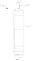
图2是图1所示血泵的省略了部分套管组件和猪尾管的结构示意图;FIG. 2 is a schematic structural diagram of the blood pump shown in FIG. 1 omitting part of the cannula assembly and pigtail tube;
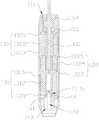
图3是图2所示的血泵沿A-A的剖视图;3 is a cross-sectional view of the blood pump shown in FIG. 2 along A-A;
图4是图1所示的血泵的驱动装置的结构示意图;Fig. 4 is the structural representation of the drive device of the blood pump shown in Fig. 1;
图5是图4所示的驱动装置的另一角度的结构示意图;FIG. 5 is a schematic structural diagram of the driving device shown in FIG. 4 from another angle;
图6是图5所示的驱动装置沿B-B线的剖视图;FIG. 6 is a cross-sectional view of the driving device shown in FIG. 5 along line B-B;
图7是图4所示的驱动装置的另一角度的结构示意图;FIG. 7 is a schematic structural diagram of the driving device shown in FIG. 4 from another angle;
图8是图7所示的驱动装置沿C-C线的剖视图;FIG. 8 is a cross-sectional view of the driving device shown in FIG. 7 along line C-C;
图9是图4所示的驱动装置的分解图;Figure 9 is an exploded view of the drive device shown in Figure 4;
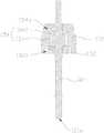
图10是图6所示的驱动装置的转轴、轴套组件和驱动壳的安装壳的剖视图;FIG. 10 is a cross-sectional view of the rotating shaft, the shaft sleeve assembly and the mounting shell of the drive housing of the drive device shown in FIG. 6;
图11是图9所示的驱动装置的轴套组件的第一轴套的另一角度的结构示意 图;Figure 11 is a schematic structural diagram of another angle of the first bushing of the bushing assembly of the drive device shown in Figure 9;
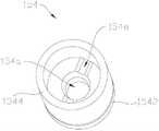
图12是图9所示的驱动装置的轴套组件的第二轴套的另一角度的结构示意 图;Figure 12 is a schematic structural diagram of another angle of the second bushing of the bushing assembly of the drive device shown in Figure 9;
图13是图10所示的驱动装置的轴套组件的剖视图;Figure 13 is a cross-sectional view of a bushing assembly of the drive device shown in Figure 10;
图14是图9所示的驱动装置的转轴的剖视图;FIG. 14 is a cross-sectional view of the rotating shaft of the drive device shown in FIG. 9;
图15是图8所示的驱动装置的转轴、轴套组件和驱动壳的安装壳的剖视图;FIG. 15 is a cross-sectional view of the rotating shaft, the bushing assembly and the mounting shell of the drive housing of the drive device shown in FIG. 8;
图16是图9所示的驱动装置的转子的磁组件的另一角度的结构示意图;FIG. 16 is a schematic structural diagram of another angle of the magnetic assembly of the rotor of the driving device shown in FIG. 9;
图17是图16所示的磁组件沿D-D线的剖视图;FIG. 17 is a cross-sectional view of the magnetic assembly shown in FIG. 16 along line D-D;
图18是图16所示的磁组件的分解图;Figure 18 is an exploded view of the magnet assembly shown in Figure 16;
图19为图9所示的驱动装置的驱动定子的另一角度的结构示意图。FIG. 19 is a schematic structural diagram of another angle of the driving stator of the driving device shown in FIG. 9 .
具体实施方式Detailed ways
为了使本申请的目的、技术方案及优点更加清楚明白,以下结合附图即实 施例,对本申请进行进一步详细说明。应当理解,此处所描述的具体实施例仅 用以解释本申请,并不用于限定本申请。In order to make the purpose, technical solutions and advantages of the present application clearer, the present application will be described in further detail below with reference to the accompanying drawings, namely the embodiments. It should be understood that the specific embodiments described herein are only used to explain the present application, but not to limit the present application.
需要说明的是,当元件被称为“固定于”或“设置于”另一个元件,它可 以直接在另一个元件上或者间接在该另一个元件上。当一个元件被称为是“连 接于”另一个元件,它可以是直接连接到另一个元件或间接连接至该另一个元 件上。It should be noted that when an element is referred to as being "fixed to" or "disposed on" another element, it can be directly on the other element or indirectly on the other element. When an element is referred to as being "connected to" another element, it can be directly connected to the other element or indirectly connected to the other element.
此外,术语“第一”、“第二”仅用于描述目的,而不能理解为指示或暗示 相对重要性或者隐含指明所指示的技术特征的数量。由此,限定有“第一”、“第 二”的特征可以明示或者隐含地包括一个或者更多个该特征。在本申请的描述 中,“多个”的含义是两个或两个以上,除非另有明确具体的限定。In addition, the terms "first" and "second" are only used for descriptive purposes, and should not be understood as indicating or implying relative importance or implying the number of indicated technical features. Thus, a feature defined as "first" or "second" may expressly or implicitly include one or more of that feature. In the description of this application, "plurality" means two or more, unless otherwise expressly and specifically defined.
为了说明本申请的技术方案,下面结合具体附图及实施例来进行说明。In order to illustrate the technical solutions of the present application, the following description is made with reference to the specific drawings and embodiments.
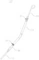
请参考图1~图3,本申请第一实施方式提供了一种血泵100,包括驱动装 置10、套管组件20和叶轮30。套管组件20与驱动装置10连接;叶轮30能够 转动地收容于套管组件20中;叶轮30与驱动装置10连接,驱动装置10能够 带动叶轮30转动,以实现血泵100的泵血功能。Referring to FIGS. 1 to 3 , the first embodiment of the present application provides a
具体地,套管组件20具有流入口21和流出口22。在其中一个实施例中, 套管组件20延伸穿过心脏瓣膜,诸如主动脉瓣膜,而流入口21位于心脏内, 流出口22和驱动装置10位于心脏外的诸如主动脉的血管中。当叶轮30旋转时, 血液从流入口21流入套管组件20中,再从流出口22流出套管组件20。Specifically, the
更具体地,套管组件20的一端与驱动装置10连接,另一端可设置猪尾管 23,猪尾管23用于稳定血泵100在心脏中的位置,为心脏组织提供无创伤支持。More specifically, one end of the
具体地,猪尾管23为中空结构。猪尾管23的材料选自聚氨酯、尼龙、聚 乙烯、聚醚嵌段聚酰胺PEBAX及乳胶材料中的至少一种。Specifically, the
进一步地,血泵100还包括导管组件40,导管组件40与驱动装置10连接, 导管组件40内设置有供应管线,供应管线包括用于给驱动装置10通入清洗流 体的清洗管线411。具体在图示的实施例中,驱动装置10位于套管组件20和 导管组件40之间。Further, the
具体地,清洗流体可以为生理盐水、含有肝素生理盐水或葡萄糖等。Specifically, the cleaning fluid may be physiological saline, physiological saline containing heparin, glucose, or the like.
请一并参阅图3~图9,驱动装置10与叶轮30传动连接,驱动装置10能 够带动血泵100的叶轮30转动。在图示的实施例中,驱动装置10包括驱动壳 11、转子12、定子机构13、固定件14和轴套组件15。Please refer to FIG. 3 to FIG. 9 together, the driving
驱动壳11具有连通口11a。连通口11a位于驱动壳11的靠近套管组件20 的一侧。具体地,连通口11a连通驱动壳11和套管组件20。叶轮30设置在驱 动壳11外。其中,清洗管线411中通入的清洗流体能够流经驱动壳11的内部, 从连通口11a流入套管组件20中,以阻止血液从驱动壳11的连通口11a渗透 到驱动壳11中。The
请一并参阅图10,驱动壳11内还设有限位部11b。本实施例中,驱动壳 11包括壳本体111及与壳本体111对接的安装壳112,连通口11a和限位部11b 均设置于安装壳112。具体地,壳本体111和安装壳112均大致为筒形。限位 部11b为设置于安装壳112的内壁上的环形凸起。安装壳112的一开口端与壳 本体111的一开口端对接,连通口11a为安装壳112的远离壳本体111的一端 的开口。其中,限位部11b位于安装壳112的远离连通口11a的一端,也即安 装壳112的靠近壳本体111的一端。Please also refer to FIG. 10 , a limiting
转子12能够转动地安装于驱动壳11,转子12部分收容于驱动壳11,部分 延伸至驱动壳11外、并与叶轮30固接,转子12能够带动叶轮30转动。The
请结合图3、图6、图8和图9,具体地,转子12包括转轴121和磁组件 122,转轴121的一端收容于驱动壳11,另一端从连通口11a延伸至驱动壳11 外、并与叶轮30固接,转轴121能够相对驱动壳11转动,磁组件122与转轴 121固接。具体地,转轴121穿设于安装壳112,一端收容于壳本体111,另一 端从连通口11a延伸至驱动壳11外而与叶轮30固接。磁组件122位于驱动壳 11的壳本体111中。3, 6, 8 and 9, specifically, the
具体地,转轴121为陶瓷或不锈钢等材料制造,例如氧化铝增韧氧化锆 (ATZ)或SUS316L等制造,以避免转轴121断裂。Specifically, the
定子机构13收容于驱动壳11,定子机构13能够产生驱动转子12旋转的 旋转磁场。具体地,定子机构13能够产生驱动磁组件122旋转的旋转磁场,以 使磁组件122能够带动转轴121绕转轴121的轴线旋转。具体地,定子机构13 收容于驱动壳11的壳本体111中。The
在其中一个实施例中,磁组件122包括第一磁体1222,第一磁体1222与 转轴121固接。定子机构13包括驱动定子131,驱动定子131与转轴121沿转 轴121的轴线间隔设置,即转轴121不穿设至驱动定子131内。驱动定子131 能够产生与第一磁体1222相互作用的旋转磁场,以使第一磁体1222能够带动 转轴121绕转轴121的轴线旋转,从而带动叶轮30旋转。其中,驱动定子131 与转轴121沿转轴121的轴线间隔设置,即转轴121不穿设至驱动定子131内, 可使得驱动定子131沿垂直于转轴121轴向的横截面更大,驱动定子131产生 的旋转磁场的磁通量更大,对第一磁体1222的扭矩也更大,从而减少了驱动定 子131在带动转轴121旋转时所需的电流,可以确保血泵100功耗更低,发热 量更少。In one embodiment, the
具体地,驱动定子131包括第一背板1311、多个第一磁芯1312及多个分 别环绕第一磁芯1312设置的第一线圈1313。第一背板1311固接于驱动壳11 内。多个第一磁芯1312环绕转轴121的轴线间隔设置一周。具体地,每个第一 磁芯1312的延伸方向均与转轴121的延伸方向平行。每个第一磁芯1312的一 端与第一背板1311固接,另一端延伸至靠近第一磁体1222。第一线圈1313能 够产生与第一磁体1222相互作用的旋转磁场,从而引起第一磁体1222旋转, 以带动转轴121旋转,叶轮30随转轴121旋转。Specifically, the driving
需要说明的是,在一些实施例中,驱动定子131也可以不具有第一背板1311。第一背板1311起到闭合磁路的作用,以促进和增加驱动定子131磁通量 的产生,提高耦合能力。由于第一背板1311能够增加磁通量,因此,设置第一 背板1311有利于减小血泵100的整体直径。第一背板1311与第一磁芯1312 的材料相同,在一些实施例中,第一背板1311与第一磁芯1312均由软磁性材 料制成,如钴钢等。It should be noted that, in some embodiments, the driving
固定件14固定于驱动壳11内,固定件14上设置有定位柱141;第一背板 1311上开设置有定位孔1311a,定位柱141穿设于定位孔1311a,从而以便于 驱动定子131的定位安装。其中,定位柱141的轴线与转轴121的轴线重合。The fixing
具体地,固定件14上开设有贯通孔142,贯通孔142与驱动壳11的内腔 连通,贯通孔142用于收容清洗管线411的一端。Specifically, the fixing
进一步地,固定件14上还开设有支撑孔143,导管组件40内还设置有支 撑件(图未示),支撑件用于在输送血泵100时支撑导管组件40和/或血泵100 的作用,支撑件的一端能够收容于支撑孔143中。具体地,支撑件例如为镍钛 丝。Further, a
请再次结合图10,轴套组件15包括安装于驱动壳11的第一轴套152和第 二轴套154,第一轴套152和第二轴套154沿转子12的旋转轴线设置,第一轴 套152和第二轴套154中的一个与限位部11b抵接,转子12能够转动地穿设于 第一轴套152和第二轴套154。其中,连通口11a能够供第一轴套152和第二 轴套154穿过。将连通口11a设置为能够供第一轴套152和第二轴套154穿过, 以使第一轴套152和第二轴套154能够从连通口11a装入驱动壳11的安装壳 112中,能够方便驱动装置10的装配和提高装配精度,提高生产效率。具体在 图示的实施例中,第一轴套152和第二轴套154均安装于安装壳112中;第二 轴套154较第一轴套152更靠近连通口11a;第一轴套152与限位部11b抵接; 转轴121能够转动地穿设于第一轴套152和第二轴套154。Referring to FIG. 10 again, the
第一轴套152和转轴121共同构成轴承结构。第一轴套152具有第一轴孔 152a,转子12(具体为转轴121)能够转动地穿设于第一轴孔152a,第一轴孔 152a的孔壁与转轴121之间具有供流体(例如清洗流体)流通的间隙。The
请一并参阅图11,具体地,第一轴套152包括盘部1522及形成在盘部1522 的一表面的圆台部1524,第一轴孔152a从盘部1522的远离圆台部1524的表 面延伸至圆台部1524的远离盘部1522的一端的端面。其中,盘部1522的远离 圆台部1524的一侧与限位部11b抵接。Please also refer to FIG. 11 , specifically, the
请一并参阅图10、图12和图13,第二轴套154与转轴121共同构成轴承 结构。其中,第二轴套154包括环本体1542及从环本体1542上延伸出的延伸 部1544,即环本体1542与延伸部1544组成一体件。通过环本体1542与延伸 部1544组成一体件能够简化驱动装置10的装配,且能够使转轴121在旋转中 更加地稳定。其中,延伸部1544与第一轴套152抵接,以使环本体1542与第 一轴套152间隔,从而对第一轴套152和环本体1542的相对位置进行定位,其 中,转子12能够转动地穿设于环本体1542。具体地,环本体1542具有第二轴 孔154a,转轴121能够转动地穿设于第二轴孔154a,第二轴孔154a的孔壁与 转轴121之间具有供流体(例如清洗流体)流通的间隙。Please refer to Fig. 10, Fig. 12 and Fig. 13 together, the
具体在图示的实施例中,延伸部1544为环形,延伸部1544与环本体1542 共轴,延伸部1544套设于圆台部1524上,延伸部1544的远离环本体1542的 一端的端面与盘部1522抵接。其中,圆台部1524的外径与延伸部1544的内径 相适配。Specifically in the illustrated embodiment, the
请再次结合图9和图10,进一步地,转轴121包括轴本体1212和环设于 轴本体1212的限位环1214,轴本体1212能够转动地穿设于第一轴套152和环 本体1542,轴本体1212的一端收容于驱动壳11,另一端从连通口11a延伸至 驱动壳11外、并与叶轮30固接;限位环1214位于环本体1542和第一轴套152 之间,且限位环1214位于轴本体1212和延伸部1544之间,限位环1214的外 径分别大于环本体1542的内径和第一轴套152的内径,以在轴本体1212的延 伸方向上对转轴121限位,避免转轴121在转轴121的延伸方向上相对于驱动 壳11发生大幅度移动。Please refer to FIG. 9 and FIG. 10 again. Further, the
其中,延伸部1544的内径大于限位环1214的外径,延伸部1544和限位环 1214之间形成供流体流通的间隙。从清洗管线411中通入驱动壳11内部的清 洗流体,流经第一轴孔152a和转轴121之间的间隙、限位环121a与延伸部1544 之间的间隙、第二轴孔154a的孔壁和转轴121之间的间隙,而从连通口11a进 入套管组件20内,不仅能够起到反冲洗的作用,还能起到转轴121和第一轴套 152之间、转轴121与第二轴套154之间的润滑作用。The inner diameter of the extending
请再次结合图11~图13,具体地,第一轴套152的朝向限位环1214的一侧 上还开设有第一导流槽152b,第一导流槽152b与第一轴孔152a连通。由于第 一导流槽152b设置在第一轴套152的朝向限位环1214的一侧,第一导流槽152b 也连通至延伸部1544和限位环1214之间的间隙,第一导流槽152b能够有利于 流体流通,降低限位环1214与第一轴套152抵接时对流体流通的影响。具体地, 第一导流槽152b开设于圆台部1524的远离盘部1522的一侧上。Please refer to FIG. 11 to FIG. 13 again. Specifically, the side of the
具体地,第二轴套154的环本体1542的朝向限位环1214的一侧上还开设 有第二导流槽154b,第二导流槽154b与第二轴孔154a连通。由于第二导流槽 154b设置环本体1542的朝向限位环1214的一侧,第二导流槽154b也连通至 延伸部1544和限位环1214之间的间隙,第二导流槽154b能够有利于流体在延 伸部1544和限位环1214之间的间隙和第二轴孔154a之间流通,降低限位环 1214与环本体1542抵接时对流体流通的影响。Specifically, the side of the
需要说明的是,在其它实施例中,还可以在第一轴套152和环本体1542 中的其中一个设置导流槽,或者不设置导流槽。It should be noted that, in other embodiments, a guide groove may also be provided in one of the
可以理解,延伸部1544不限于为环形,在一个实施例中,延伸部1544为 杆状结构,延伸部1544为多个,多个延伸部1544环绕转子的旋转轴线设置, 第一轴套152上还开设有定位槽,延伸部1544的远离环本体1542的一端收容 于定位槽中,以对第二轴套154定位。It can be understood that the
具体地,第一轴套152的靠近环本体1542的一侧的孔径大于第一轴套152 的背离环本体1542的一侧的孔径。如此设置,不仅能够较小第一轴套152与转 轴121之间接触面积,减小摩擦,而且有利于流体的流动,以及减小转轴121 的晃动幅度。Specifically, the hole diameter of the side of the
具体地,环本体1542的靠近第一轴套152的一侧的孔径大于环本体1542 的背离第一轴套152的一侧的孔径。如此设置,不仅能够较小环本体1542与转 轴121之间接触面积,减小摩擦,而且有利于流体的流动,以及减小转轴121 的晃动幅度和防止套管组件20中的血液通过第二轴孔154a进入驱动壳11中。Specifically, the hole diameter of the side of the
在其中一个实施例中,环本体1542的远离第一轴套152的一端与转轴121 之间的间隙小于或等于2μm。由于最小的红血球(直径约为8μm,厚度约为2μm) 难以进入宽度小于或等于2μm的间隙,加之反向冲洗的清洗流体经过此间隙, 阻止了血液通过第二轴孔154a进入驱动壳11的内部。In one embodiment, the gap between the end of the
具体地,第二轴孔154a具有直孔部154c及与直孔部154c连通的锥形孔部 154d,锥形孔部154d的孔径较小的一端与直孔部154c连通,孔径较大的一端 朝向环本体1542,转子12(具体为转轴121)能够转动地穿设于直孔部154c 和锥形孔部154d。Specifically, the
具体地,直孔部154c在转子12的旋转轴线方向上的长度大于或等于0.5 毫米。即在图示的实施例中,直孔部154c在转轴121的延伸方向上的长度大于 或等于0.5毫米,以更好地对转轴121进行支撑。Specifically, the length of the
在图示的实施例中,第一轴孔152a也类似于第二轴孔154a,具有直孔部 和锥形孔部,第一轴孔152a的锥形孔部较其直孔部更靠近环本体1542。In the illustrated embodiment, the
可以理解,第一轴孔152a和第二轴孔154a也不限于为上述结构,在其它 实施例中,第二轴孔154a也可以为从靠近第一轴套154的一侧到远离第一轴套 154的一侧,第二轴孔154a的逐渐减小;在与图13所示的视角相同的视角下, 第二轴孔154a的孔壁可以相对于转轴121的延伸方向呈倾斜的直面,或者呈弧 面状;或者,从靠近第一轴套154的一侧到远离第一轴套154的一侧,第二轴 孔154的孔径相等。第一轴孔152a也可以为第二轴孔154a类似的构造。在同 一个实施例中,第一轴孔152a和第二轴孔154a的构造可以基本相同,也可以 不相同。It can be understood that the
请参阅图14,具体地,限位环1214具有外环面1214a及与外环面1214a 连接的两端面1214b,外环面1214a和两端面1214b的连接处均设有倒角1214c。 在外环面1214a和和两端1214b面的连接处均设置倒角1214c,不仅能够降低 限位环1214与第一轴套152、第二轴套154之间的摩擦,而且还有利于流体的 流通。Please refer to FIG. 14 , specifically, the limiting
请结合图15,具体地,第一轴套152和第二轴套154均与驱动壳11固定 连接。在其中一个实施例中,第一轴套152和第二轴套154均与驱动壳11通过 胶黏剂粘结固定。具体在图示的实施例中,安装壳112的靠近壳本体111的一 端开设有与安装壳112的内孔连通的第一置胶槽112a,第一置胶槽112a中的胶 黏剂将安装壳112、第一轴套152和延伸部1544的远离环本体1542的一端粘 接固定。第二轴套154的外壁上还开设有第二置胶槽154e,第二置胶槽154e 中的胶黏剂将安装壳112、第二轴套154固定粘结。Please refer to FIG. 15 , specifically, both the
请再次结合图8,进一步地,磁组件122还包括第二磁体1223,第二磁体 1223与转轴121固定连接;定子机构13还包括动力定子132,动力定子132 和驱动定子131沿转轴121的轴线设置,且动力定子132较驱动定子131更靠 近叶轮30,即在转轴121的延伸方向上,动力定子132布置在叶轮30和驱动 定子131之间。其中,转轴121能够转动地穿设于动力定子132,动力定子132 能够产生与第二磁体1223相互作用的旋转磁场。驱动定子131和动力定子132 能够分别驱动第一磁体1222和第二磁体1223转动,而使驱动定子131和动力 定子132能够共同带动转轴121绕转轴121的轴线旋转,从而带动叶轮30旋转, 以给叶轮30的旋转提供更大的驱动力。Referring again to FIG. 8 , further, the
在图示的实施例中,第一磁体1222和第二磁体1223布置在驱动定子131 和动力定子132之间。具体地,磁组件122还包括与转轴121固接的飞轮1224, 飞轮1224位于动力定子132和驱动定子131之间,第一磁体1222和第二磁体 1223均设置在飞轮1224上。In the illustrated embodiment, the
飞轮1224固定地套设在转轴121的远离叶轮30的一端。其中,飞轮1224 与转轴121可以为一体成型,或者通过粘接、焊接等方式与转轴121固定。The
通过设置飞轮1224可以增加磁体与转轴121的连接强度,提高转轴121 旋转的稳定性;另外,通过将第一磁体1222和第二磁体1223均设置在同一个 飞轮1224上,能够减少转轴121在旋转过程中的晃动,使转轴121在旋转过程 中更加稳定。By arranging the
请结合图16和图17,飞轮1224包括盘状部1224a和管状部1224b,管状 部1224b固定地穿设于盘状部1224a的中部、并与盘状部1224a共轴,转轴121 的远离叶轮30的一端固定地收容于管状部1224b内,第一磁体1222和第二磁 体1223分别设置在盘状部1224a的相背离的两侧,从而方便第一磁体1222和 第二磁体1223的装配,以便于更好地将第一磁体1222和第二磁体1223与转轴 121固定。16 and FIG. 17, the
请结合图18,具体地,第一磁体1222和第二磁体1223均为环状的海尔贝 克阵列磁铁。第一磁体1222包括多个充磁方向与第一磁体1222的轴线平行的 第一磁块1222a,第二磁体1223包括多个充磁方向与第二磁体1223的轴线平 行的第二磁块1223a,多个第二磁块1223a和多个第一磁块1222a分别环绕转 轴121设置在盘状部1224a的相背离的两侧。在转轴121的延伸方向上,每个 第二磁块1223a与一个第一磁块1222a相对设置,且相对设置的第二磁块1223a 与第一磁块1222a的朝向盘状部1224a的一侧的极性相反。如此设置可以方便 第一磁体1222和第二磁体1223的安装,避免第一磁体1222的磁块和第二磁体 1223的磁块相互排斥而造成装配困难的问题。Please refer to FIG. 18 , specifically, the
在一些实施例中,第一磁体1222还包括多个沿第一磁体1222的周向充磁 的第三磁块1222b,周向充磁的第三磁块1222b和沿平行于第一磁体1222的轴 线充磁的第一磁块1222a沿第一磁体1222所在的圆周交替设置。其中,相邻的 第一磁块1222a的充磁方向相反,例如,相邻的第一磁体1222中的一个的充磁 方向是从第一磁块1222a的背离盘状部1224a的一侧指向朝向盘状部1224a的 一侧,另一个的充磁方向则为从第一磁块1222a的朝向盘状部1224a的一侧指 向背离盘状部1224a的一侧。相邻的第三磁块1222b的充磁方向在第一磁体1222 所在的圆周上相反。In some embodiments, the
对应地,第二磁体1223还包括多个沿第二磁体1223的周向充磁的第四磁 块1223b,第四磁块1223b和第二磁块1223a沿第二磁体1223所在的圆周交替 设置。其中,相邻的第二磁块1223a的充磁方向相反,相邻的第四磁块1223b 的充磁方向在第二磁体1223所在的圆周上相反。Correspondingly, the
需要说明的是,第三磁块1222b和第四磁块1223b的充磁方向不限于为周 向充磁,在一些实施例中,第三磁块1222b和第四磁块1223b的充磁方向还可 以为相对转轴121的轴线是倾斜的。It should be noted that the magnetization directions of the
本实施例中,第一磁体1222和第二磁体1223均设置八个磁块,即,第一 磁块1222a、第二磁块1223a、第三磁块1222b和第四磁块1223b均为四个。第 一磁块1222a、第二磁块1223a、第三磁块1222b和第四磁块1223b均为扇环形 磁铁,第一磁体1222和第二磁体1223大致为圆环状结构。可以理解的是,在 其他实施例中,第一磁体1222和第二磁体1223还可以由更多或更少的磁块组 成,如两个、四个、六个或十个等。In this embodiment, the
为了方便第一磁体1222和第二磁体1223的安装,飞轮1224上还设有用于 确定第一磁块1222a的安装位置和第二磁块1223a的安装位置的标识部1224c。 标识部1224c可以设置为槽、刻度线或者是标识等。在安装第一磁块1222a和 第二磁块1223a时,只要使用标识部1224c标识出其中一个第一磁块1222a和 其中一个第二磁块1223a的位置,就可以确定剩余磁块的安装位置,从而方便 第一磁体1222和第二磁体1223的安装。具体地,标识部1224c可以在管状部 1224b及盘状部1224a中的至少一个上。In order to facilitate the installation of the
在其中一个实施例中,飞轮1224通过粘接的方式与转轴121固定。请结合 图15和图17,转轴121的远离叶轮30的一端的端部开设有点胶槽121a,管状 部1224b的内壁上设置与点胶槽121a相抵接的止位凸起1224d。如此可以通过 在点胶槽121a内布置胶水以方便转轴121与止位凸起1224d固接。In one embodiment, the
进一步地,点胶槽121a沿垂直于转轴121的轴线方向延伸,且点胶槽121a 的端部延伸至转轴121的外圆周面。如此设置可以使对点胶槽121a布置胶水, 胶水溢流至转轴121的外圆周面,以粘接管状部1224b的内周壁和转轴121的 周面,使得转轴121与飞轮1224之间可以更好地固定,或者,也方便用于粘结 转轴121和管状部1224b之间的多余的胶水溢流到点胶槽121a中。Further, the
在本实施例中,飞轮1224还包括环绕盘状部1224a设置的外环壁1224e, 外环壁1224e、管状部1224b和盘状部1224a共同围设出分别容置第一磁体1222 和第二磁体1223的第一容置部和第二容置部,且第一容置部和第二容置部被盘 状部1224a分隔。如此设置能够对第一磁体1222和第二磁体1223限位,不仅 方便第一磁体1222和第二磁体1223的安装,而且也使得第一磁体1222和第二 磁体1223和飞轮1224结合更加稳固。In this embodiment, the
在本实施例中,在管状部1224b的轴向上,第一磁体1222的背离盘状部 1224a的一侧高出外环壁1224e一段距离,第二磁体1223的背离盘状部1224a 的一侧高出外环壁1224e一段距离,以方便第一磁体1222、第二磁体1223装 配于飞轮1224上。In this embodiment, in the axial direction of the
需要说明的是,飞轮1224不限于为上述结构,在一些实施例中,飞轮1224 不具有外环壁1224e;在一些实施例中,飞轮1224不具有外环壁1224e和管状 部1224b,此时,转轴121固定地穿设于盘状部1224a,例如,盘状部1224a的 中心。相对于仅具有盘状部1224a的飞轮1224,设置管状部1224b能够使飞轮 1224与转轴121更加稳定地连接。It should be noted that the
请结合图8,动力定子132的结构与驱动定子131的结构类似。其中,动 力定子132包括第二背板1321、多个第二磁芯1322及多个第二线圈1323。多 个第二磁芯1322环绕转轴121间隔设置一周,每个第二磁芯1322的延伸方向 均与转轴121的轴线平行。每个第二磁芯1322的一端与第二背板1321固接, 另一端延伸至靠近第二磁体1223。换而言之,在转轴121的轴向上,驱动定子 131和动力定子132反向设置。每个第二线圈1323分别缠于相应的第二磁芯 1322。第二线圈1323能够产生与第二磁体1223相互作用的旋转磁场。Please refer to FIG. 8 , the structure of the
其中,第一磁芯1312和第二磁芯1322包括磁柱,第一线圈1313缠绕于第 一磁芯1312的磁柱上,第二线圈1323缠绕在第二磁芯1322的磁柱上。第一磁 芯1312的磁柱的横截面积大于第二磁芯1322的磁柱的横截面积。即第一磁芯 1312的磁柱比第二磁芯1322的磁柱粗。The first
磁柱的横截面积越大,所产生的磁通量就越大,定子对磁体的扭矩就越大, 所需电流越小,有利于降低功耗,减少发热。由于动力定子132的中部有转轴 121穿过,受到血泵100径向尺寸的限制,限制了第二磁芯1322的横截面积, 而驱动定子131的中部没有转轴121穿过,使得第一磁芯1312能够选择较大的 横截面积,换而言之,如此设置可以降低功耗,减少驱动装置10发热。The larger the cross-sectional area of the magnetic column, the larger the generated magnetic flux, the larger the torque of the stator to the magnet, and the smaller the required current, which is beneficial to reduce power consumption and heat generation. Because the
在本实施例中,第一磁芯1312和第二磁芯1322均仅具有磁柱,即第一磁 芯1312和第二磁芯1322均没有宽度较大的头部(即极靴),在第一磁芯1312 和第二磁芯1322的长度方向上,其宽度是恒定的,整个第一磁芯1312均能够 与第一磁体1222进行磁耦合,整个第二磁芯1322均能够与第二磁体1223进行 磁耦合,相较于设置有极靴的磁芯,本申请能够减少磁损耗,增加第一磁芯1312 和第一磁体1222、第二磁芯1322和第二磁体1223之间的磁耦合密度,以增大 驱动定子131对第一磁体1222的扭矩(在相等电流条件下)和动力定子132对第二磁体1223的扭矩(在相等电流条件下)。另外,没有头部的第一磁芯 1312和第二磁芯1322还能够大大降低相邻磁芯之间的接触而导致的局部磁短 路造成的电机功率降低的问题。In this embodiment, both the first
仅具有磁柱的第一磁芯1312和第二磁芯1322的横截面的形状可以为扇形、 圆形、梯形、扇环形等等。如图19所示,在图示的实施例中,仅具有磁柱的第 一磁芯1312和第二磁芯1322大致为三棱柱状,每个磁芯的一个棱边朝向转轴 121的轴线。在本实施例中,第一磁芯1312和第二磁芯1322的棱边均做了倒 圆处理,通过将棱边倒圆处理可以方便后续线圈的缠绕,同时有利于保护线圈 上包覆的绝缘材料。The shape of the cross section of the first
可以理解,在其它实施例中,第一磁芯1312和第二磁芯1322还可以包括 设置在磁柱的一端的头部,第一背板1311与第一磁芯1312的磁柱的远离头部 的一端接合;第二背板1321与第二磁芯1322的磁柱的远离头部的一端结合。 或者,在一些实施例中,还可以为第一磁芯1312和第二磁芯1322中的一个同 时具有磁柱和头部,另一个仅具有磁柱。It can be understood that, in other embodiments, the first
请再次参阅图14,为了使动力定子132的第二磁芯1322尽可能地粗,穿 设于动力定子132的转轴121需较细,但是考虑到转轴121与轴套组件15需要 配合,转轴121又需要较大的刚度和较耐磨,为此,转轴121的轴本体1212 具有第一配合段1212a和第二配合段1212b,在垂直于轴本体1212的延伸方向 上,第一配合段1212a的横截面积大于第二配合段1212b的横截面积,即第一 配合段1212a比第二配合段1212b要粗,第一配合段1212a穿设于轴套组件15, 第二配合段1212b穿设于动力定子132。其中,限位环1214固定地设置于第一配合段1212a上。Please refer to FIG. 14 again, in order to make the second
为了避免清洗流体被污染和/或驱动装置10内的元件被腐蚀,驱动装置10 的驱动定子131和动力定子132上均上包覆有防水密封膜。其中,防水密封膜 的材料可以为硅胶、胶水等。In order to prevent the cleaning fluid from being polluted and/or the components in the driving
上述驱动装置10至少具有以下优点:The
(1)上述驱动装置10用于支撑转子12的第一轴套152和第二轴套154 沿转子12的旋转轴线设置,且第一轴套152和第二轴套154中的一个与驱动壳 11的限位件11b抵接,以支撑第一轴套152和第二轴套154中的一个,第二轴 套154的支撑转子12的环本体1542通过第二轴承154的延伸部1544与第一轴 套152抵接,以支撑分隔环本体1542和第一轴套152,以更好地支撑转子12; 且延伸部1544和环本体1542为一体件,能够减少零件的装配,有利于简化驱 动装置10的装配;进一步将连通口11a设置为能够供第一轴套152和第二轴套154穿过,以使第一轴套152和第二轴套154能够从连通口11a装入驱动壳11 的安装壳112中,以使驱动装置10的装配更加方便;且上述结构设计使得驱动 装置10不仅装配简单方便,而且能够提高驱动装置10的装配精度,提高生产 效率。(1) The
(2)通过在转轴121上设置限位环1214,限位环1214的外径分别大于环 本体1542的内径和第一轴套152的内径,以在轴本体1212的延伸方向上对转 轴121限位,避免转轴121在转轴121的延伸方向上相对于驱动壳11发生大幅 度移动;而通过设置第一导流槽152b和/或第二导流槽154b,能够有利于流体 流通,降低限位环1214与第一轴套152或环本体1542抵接时对流体流通的影 响。(2) By disposing the limiting
(3)将第一轴套152的靠近环本体1542的一侧的孔径设置为大于第一轴 套152的背离环本体1542的一侧的孔径,环本体1542的靠近第一轴套152的 一侧的孔径大于环本体1542的背离第一轴套152的一侧的孔径,不仅可以使第 一轴套152和环本体1542起到支撑转轴121的部分相隔尽可能远,以尽可能地 降低转轴121的晃动幅度,而且还可以减少轴套组件15与转轴121之间的接触 面积,减小摩擦,另外还有利于流体(例如清洗流体)的流动。(3) The hole diameter of the side of the
(4)将第二轴孔154a的直孔部154c在转轴121的延伸方向上的长度大于 或等于0.5毫米,以更好地实现对转轴121的支撑。(4) The length of the
(5)将驱动定子131与转轴121沿转轴121的轴线间隔设置,可使得驱动 定子131沿垂直于转轴121轴向的横截面更大,驱动定子131产生的旋转磁场 的磁通量更大,对第一磁体1222的扭矩也更大,从而减少了驱动定子131在带 动转轴121旋转时所需的电流,可以确保血泵100功耗更低,发热量更少;通 过进一步地设置动力定子132,而使驱动定子131和动力定子132能够共同带 动转轴121绕转轴121的轴线旋转,从而带动叶轮30旋转,以给叶轮30的旋 转提供更大的驱动力。(5) Disposing the driving
需要说明的是,驱动装置10不限于为上述结构,在一些实施例中,驱动装 置10具有两个飞轮,两个飞轮均设置在动力定子132和驱动定子131之间,两 个飞轮均与转轴121固接,且沿转轴121的旋转轴线布置,第一磁体1222和第 二磁体1223分别安装于两个飞轮上。It should be noted that the driving
可以理解,此时,转子12也可以不具有飞轮;或者,飞轮为一个,该飞轮 用于安装第一磁体1222和第二磁体1223中的一个。It can be understood that, at this time, the
或者,动力定子132位于两个飞轮之间,即一个飞轮位于叶轮30和动力定 子132之间,另一个飞轮位于动力定子132和驱动定子131之间,第一磁体1222 固定在动力定子132和驱动定子131之间的飞轮上,第二磁体1223固定在叶轮 30和动力定子132之间的飞轮上,即,第一磁体1222位于动力定子132和驱 动定子131之间,第二磁体1223位于叶轮30和动力定子132之间。可以理解, 此时,转子12也可以不具有飞轮。Alternatively, the
或者,在一些实施例中,转轴121也可以设置为穿设于驱动定子131,转 轴121穿设于驱动定子131和动力定子132,此时,整个磁组件122可以设置 在驱动定子131和动力定子132之间;或者,动力定子132位于第一磁体1222 和第二磁体1223之间,或者,驱动定子131和动力定子132均位于第一磁体 1222和第二磁体1223之间。可以理解,此时,转子12也可以不具有飞轮。Alternatively, in some embodiments, the
或者,在一些实施例中,驱动装置10仅具有动力定子132和驱动定子131 中的一个。Alternatively, in some embodiments, the
以上实施例仅用以说明本申请的技术方案,而非对其限制;尽管参照前述 实施例对本申请进行了详细的说明,本领域的普通技术人员应当理解:其依然 可以对前述各实施例所记载的技术方案进行修改,或者对其中部分技术特征进 行等同替换;而这些修改或者替换,并不使相应技术方案的本质脱离本申请各 实施例技术方案的精神和范围,均应包含在本申请的保护范围之内。The above embodiments are only used to illustrate the technical solutions of the present application, but not to limit them; although the present application has been described in detail with reference to the foregoing embodiments, those of ordinary skill in the art should understand that: The recorded technical solutions are modified, or some technical features thereof are equivalently replaced; and these modifications or replacements do not make the essence of the corresponding technical solutions deviate from the spirit and scope of the technical solutions of the embodiments of the application, and should be included in the application. within the scope of protection.
Claims (15)
Priority Applications (2)
| Application Number | Priority Date | Filing Date | Title |
|---|---|---|---|
| CN202210169758.2ACN114870242A (en) | 2022-02-23 | 2022-02-23 | Blood pump and its driving device |
| PCT/CN2023/075745WO2023160424A1 (en) | 2022-02-23 | 2023-02-13 | Blood pump and driver apparatus thereof |
Applications Claiming Priority (1)
| Application Number | Priority Date | Filing Date | Title |
|---|---|---|---|
| CN202210169758.2ACN114870242A (en) | 2022-02-23 | 2022-02-23 | Blood pump and its driving device |
Publications (1)
| Publication Number | Publication Date |
|---|---|
| CN114870242Atrue CN114870242A (en) | 2022-08-09 |
Family
ID=82667088
Family Applications (1)
| Application Number | Title | Priority Date | Filing Date |
|---|---|---|---|
| CN202210169758.2APendingCN114870242A (en) | 2022-02-23 | 2022-02-23 | Blood pump and its driving device |
Country Status (2)
| Country | Link |
|---|---|
| CN (1) | CN114870242A (en) |
| WO (1) | WO2023160424A1 (en) |
Cited By (3)
| Publication number | Priority date | Publication date | Assignee | Title |
|---|---|---|---|---|
| CN115382092A (en)* | 2022-09-05 | 2022-11-25 | 深圳核心医疗科技有限公司 | Drives and blood pumps |
| WO2023160422A1 (en)* | 2022-02-23 | 2023-08-31 | 深圳核心医疗科技有限公司 | Blood pump and driving device therefor |
| WO2023160424A1 (en)* | 2022-02-23 | 2023-08-31 | 深圳核心医疗科技有限公司 | Blood pump and driver apparatus thereof |
Citations (14)
| Publication number | Priority date | Publication date | Assignee | Title |
|---|---|---|---|---|
| US5911685A (en)* | 1996-04-03 | 1999-06-15 | Guidant Corporation | Method and apparatus for cardiac blood flow assistance |
| CN102481398A (en)* | 2009-07-01 | 2012-05-30 | 宾夕法尼亚州研究基金会 | Blood pump with expandable cannula |
| CN106151055A (en)* | 2015-03-26 | 2016-11-23 | 杭州三花研究院有限公司 | Electric drive pump |
| CN111375098A (en)* | 2018-12-29 | 2020-07-07 | 上海微创心力医疗科技有限公司 | Percutaneous blood pump and rotor limit structure thereof |
| CN211693252U (en)* | 2020-01-07 | 2020-10-16 | 丰凯医疗器械(上海)有限公司 | Sealing structure capable of isolating bearing wear particles |
| CN111971080A (en)* | 2018-03-23 | 2020-11-20 | 阿比奥梅德欧洲股份有限公司 | Intravascular blood pump with ceramic inner sleeve |
| CN112472999A (en)* | 2020-12-22 | 2021-03-12 | 余顺周 | Blood pump |
| CN112494803A (en)* | 2020-12-22 | 2021-03-16 | 余顺周 | Blood pump |
| CN112587792A (en)* | 2020-12-22 | 2021-04-02 | 余顺周 | Blood pump |
| WO2021152013A1 (en)* | 2020-01-31 | 2021-08-05 | Ecp Entwicklungsgesellschaft Mbh | Intravascular blood pump |
| CN113599692A (en)* | 2021-08-05 | 2021-11-05 | 深圳核心医疗科技有限公司 | Blood pump |
| CN215025224U (en)* | 2020-12-22 | 2021-12-07 | 深圳核心医疗科技有限公司 | Blood pump |
| CN215025223U (en)* | 2020-12-22 | 2021-12-07 | 深圳核心医疗科技有限公司 | Blood pump |
| CN215084231U (en)* | 2020-12-22 | 2021-12-10 | 深圳核心医疗科技有限公司 | Blood pump |
Family Cites Families (6)
| Publication number | Priority date | Publication date | Assignee | Title |
|---|---|---|---|---|
| JP3725323B2 (en)* | 1998-02-23 | 2005-12-07 | 日創電機株式会社 | Drive motor and drive device for molding machine |
| CN108815601B (en)* | 2018-10-15 | 2019-01-29 | 上海微创医疗器械(集团)有限公司 | Magnetic coupling centrifugal blood pump and blood pump pedestal |
| CN114796846B (en)* | 2021-12-03 | 2023-07-11 | 深圳核心医疗科技股份有限公司 | Blood pump and driving device thereof |
| CN114870241B (en)* | 2021-12-03 | 2024-08-27 | 深圳核心医疗科技股份有限公司 | Driving device and blood pump |
| CN114796849A (en)* | 2022-02-23 | 2022-07-29 | 深圳核心医疗科技有限公司 | Blood pump and driving device thereof |
| CN114870242A (en)* | 2022-02-23 | 2022-08-09 | 深圳核心医疗科技有限公司 | Blood pump and its driving device |
- 2022
- 2022-02-23CNCN202210169758.2Apatent/CN114870242A/enactivePending
- 2023
- 2023-02-13WOPCT/CN2023/075745patent/WO2023160424A1/ennot_activeCeased
Patent Citations (14)
| Publication number | Priority date | Publication date | Assignee | Title |
|---|---|---|---|---|
| US5911685A (en)* | 1996-04-03 | 1999-06-15 | Guidant Corporation | Method and apparatus for cardiac blood flow assistance |
| CN102481398A (en)* | 2009-07-01 | 2012-05-30 | 宾夕法尼亚州研究基金会 | Blood pump with expandable cannula |
| CN106151055A (en)* | 2015-03-26 | 2016-11-23 | 杭州三花研究院有限公司 | Electric drive pump |
| CN111971080A (en)* | 2018-03-23 | 2020-11-20 | 阿比奥梅德欧洲股份有限公司 | Intravascular blood pump with ceramic inner sleeve |
| CN111375098A (en)* | 2018-12-29 | 2020-07-07 | 上海微创心力医疗科技有限公司 | Percutaneous blood pump and rotor limit structure thereof |
| CN211693252U (en)* | 2020-01-07 | 2020-10-16 | 丰凯医疗器械(上海)有限公司 | Sealing structure capable of isolating bearing wear particles |
| WO2021152013A1 (en)* | 2020-01-31 | 2021-08-05 | Ecp Entwicklungsgesellschaft Mbh | Intravascular blood pump |
| CN112494803A (en)* | 2020-12-22 | 2021-03-16 | 余顺周 | Blood pump |
| CN112587792A (en)* | 2020-12-22 | 2021-04-02 | 余顺周 | Blood pump |
| CN112472999A (en)* | 2020-12-22 | 2021-03-12 | 余顺周 | Blood pump |
| CN215025224U (en)* | 2020-12-22 | 2021-12-07 | 深圳核心医疗科技有限公司 | Blood pump |
| CN215025223U (en)* | 2020-12-22 | 2021-12-07 | 深圳核心医疗科技有限公司 | Blood pump |
| CN215084231U (en)* | 2020-12-22 | 2021-12-10 | 深圳核心医疗科技有限公司 | Blood pump |
| CN113599692A (en)* | 2021-08-05 | 2021-11-05 | 深圳核心医疗科技有限公司 | Blood pump |
Cited By (3)
| Publication number | Priority date | Publication date | Assignee | Title |
|---|---|---|---|---|
| WO2023160422A1 (en)* | 2022-02-23 | 2023-08-31 | 深圳核心医疗科技有限公司 | Blood pump and driving device therefor |
| WO2023160424A1 (en)* | 2022-02-23 | 2023-08-31 | 深圳核心医疗科技有限公司 | Blood pump and driver apparatus thereof |
| CN115382092A (en)* | 2022-09-05 | 2022-11-25 | 深圳核心医疗科技有限公司 | Drives and blood pumps |
Also Published As
| Publication number | Publication date |
|---|---|
| WO2023160424A1 (en) | 2023-08-31 |
Similar Documents
| Publication | Publication Date | Title |
|---|---|---|
| CA3160944C (en) | Blood pump | |
| CN114870242A (en) | Blood pump and its driving device | |
| CN114796849A (en) | Blood pump and driving device thereof | |
| JP7638029B2 (en) | Blood pump and its drive device | |
| CN114768088A (en) | Drive and blood pump | |
| EP4299103A1 (en) | Blood pump and driving device thereof | |
| CN114917469A (en) | Drives and blood pumps | |
| EP4477252A1 (en) | Driving device and blood pump | |
| JP2025521309A (en) | Driving device and blood pump | |
| CN115282467B (en) | Driving mechanism and blood pump | |
| CN115192894A (en) | Drive device and blood pump | |
| EP4393537A1 (en) | Driving apparatus and blood pump | |
| CN115025387B (en) | Driving device and blood pump | |
| CN115006715A (en) | Drives and blood pumps | |
| WO2024007813A1 (en) | Driving mechanism and blood pump | |
| WO2023236717A1 (en) | Driving device and blood pump | |
| WO2024021918A1 (en) | Driving apparatus and blood pump |
Legal Events
| Date | Code | Title | Description |
|---|---|---|---|
| PB01 | Publication | ||
| PB01 | Publication | ||
| SE01 | Entry into force of request for substantive examination | ||
| SE01 | Entry into force of request for substantive examination |