CN114869392A - Supporting device and assembling method - Google Patents
Supporting device and assembling methodDownload PDFInfo
- Publication number
- CN114869392A CN114869392ACN202210596476.0ACN202210596476ACN114869392ACN 114869392 ACN114869392 ACN 114869392ACN 202210596476 ACN202210596476 ACN 202210596476ACN 114869392 ACN114869392 ACN 114869392A
- Authority
- CN
- China
- Prior art keywords
- catheter
- elastic balloon
- conduit
- injection channel
- hole
- Prior art date
- Legal status (The legal status is an assumption and is not a legal conclusion. Google has not performed a legal analysis and makes no representation as to the accuracy of the status listed.)
- Pending
Links
Images


Classifications
- A—HUMAN NECESSITIES
- A61—MEDICAL OR VETERINARY SCIENCE; HYGIENE
- A61B—DIAGNOSIS; SURGERY; IDENTIFICATION
- A61B17/00—Surgical instruments, devices or methods
- A61B17/12—Surgical instruments, devices or methods for ligaturing or otherwise compressing tubular parts of the body, e.g. blood vessels or umbilical cord
- A61B17/12022—Occluding by internal devices, e.g. balloons or releasable wires
- A61B17/12027—Type of occlusion
- A61B17/12031—Type of occlusion complete occlusion
- A—HUMAN NECESSITIES
- A61—MEDICAL OR VETERINARY SCIENCE; HYGIENE
- A61B—DIAGNOSIS; SURGERY; IDENTIFICATION
- A61B17/00—Surgical instruments, devices or methods
- A61B17/12—Surgical instruments, devices or methods for ligaturing or otherwise compressing tubular parts of the body, e.g. blood vessels or umbilical cord
- A61B17/12022—Occluding by internal devices, e.g. balloons or releasable wires
- A61B17/12099—Occluding by internal devices, e.g. balloons or releasable wires characterised by the location of the occluder
- A—HUMAN NECESSITIES
- A61—MEDICAL OR VETERINARY SCIENCE; HYGIENE
- A61B—DIAGNOSIS; SURGERY; IDENTIFICATION
- A61B17/00—Surgical instruments, devices or methods
- A61B17/12—Surgical instruments, devices or methods for ligaturing or otherwise compressing tubular parts of the body, e.g. blood vessels or umbilical cord
- A61B17/12022—Occluding by internal devices, e.g. balloons or releasable wires
- A61B17/12131—Occluding by internal devices, e.g. balloons or releasable wires characterised by the type of occluding device
- A61B17/12136—Balloons
- A—HUMAN NECESSITIES
- A61—MEDICAL OR VETERINARY SCIENCE; HYGIENE
- A61M—DEVICES FOR INTRODUCING MEDIA INTO, OR ONTO, THE BODY; DEVICES FOR TRANSDUCING BODY MEDIA OR FOR TAKING MEDIA FROM THE BODY; DEVICES FOR PRODUCING OR ENDING SLEEP OR STUPOR
- A61M25/00—Catheters; Hollow probes
- A61M25/0021—Catheters; Hollow probes characterised by the form of the tubing
- A61M25/0023—Catheters; Hollow probes characterised by the form of the tubing by the form of the lumen, e.g. cross-section, variable diameter
- A61M25/0026—Multi-lumen catheters with stationary elements
- A—HUMAN NECESSITIES
- A61—MEDICAL OR VETERINARY SCIENCE; HYGIENE
- A61M—DEVICES FOR INTRODUCING MEDIA INTO, OR ONTO, THE BODY; DEVICES FOR TRANSDUCING BODY MEDIA OR FOR TAKING MEDIA FROM THE BODY; DEVICES FOR PRODUCING OR ENDING SLEEP OR STUPOR
- A61M25/00—Catheters; Hollow probes
- A61M25/0043—Catheters; Hollow probes characterised by structural features
- A—HUMAN NECESSITIES
- A61—MEDICAL OR VETERINARY SCIENCE; HYGIENE
- A61M—DEVICES FOR INTRODUCING MEDIA INTO, OR ONTO, THE BODY; DEVICES FOR TRANSDUCING BODY MEDIA OR FOR TAKING MEDIA FROM THE BODY; DEVICES FOR PRODUCING OR ENDING SLEEP OR STUPOR
- A61M25/00—Catheters; Hollow probes
- A61M25/10—Balloon catheters
- A61M25/1018—Balloon inflating or inflation-control devices
- A—HUMAN NECESSITIES
- A61—MEDICAL OR VETERINARY SCIENCE; HYGIENE
- A61M—DEVICES FOR INTRODUCING MEDIA INTO, OR ONTO, THE BODY; DEVICES FOR TRANSDUCING BODY MEDIA OR FOR TAKING MEDIA FROM THE BODY; DEVICES FOR PRODUCING OR ENDING SLEEP OR STUPOR
- A61M25/00—Catheters; Hollow probes
- A61M25/10—Balloon catheters
- A61M25/1027—Making of balloon catheters
Landscapes
- Health & Medical Sciences (AREA)
- Life Sciences & Earth Sciences (AREA)
- Heart & Thoracic Surgery (AREA)
- General Health & Medical Sciences (AREA)
- Veterinary Medicine (AREA)
- Engineering & Computer Science (AREA)
- Biomedical Technology (AREA)
- Public Health (AREA)
- Animal Behavior & Ethology (AREA)
- Surgery (AREA)
- Anesthesiology (AREA)
- Hematology (AREA)
- Pulmonology (AREA)
- Biophysics (AREA)
- Reproductive Health (AREA)
- Vascular Medicine (AREA)
- Nuclear Medicine, Radiotherapy & Molecular Imaging (AREA)
- Medical Informatics (AREA)
- Molecular Biology (AREA)
- Child & Adolescent Psychology (AREA)
- Media Introduction/Drainage Providing Device (AREA)
Abstract
Translated fromChinese
Description
Translated fromChinese技术领域technical field
本发明实施例涉及医疗器械技术领域,特别是涉及一种支撑装置及装配方法。The embodiments of the present invention relate to the technical field of medical devices, and in particular, to a support device and an assembling method.
背景技术Background technique
经蝶窦入路垂体瘤切除手术是治疗垂体瘤的常用手术,在切除了垂体瘤后,需要对鞍底进行修复,根据鞍膈膜损坏程度使用自体鼻软骨材料及止血棉纱、明胶海绵、生物胶等填充材料对创口进行封堵。Transsphenoidal pituitary tumor resection is a common operation for pituitary tumors. After the pituitary tumor is removed, the sellar floor needs to be repaired. According to the degree of damage to the sellar diaphragm, autologous nasal cartilage materials and hemostatic cotton gauze, gelatin sponge, biological Filling material such as glue to seal the wound.
本发明实施例的发明人实现本发明的过程中,发现:目前在进行鞍底修复时,使用填充材料将鞍隔膜的缺口封堵后,缺少合适的支撑装置,以用于支撑封堵缺口的填充材料。During the process of realizing the present invention, the inventors of the embodiments of the present invention found that: at present, when the saddle bottom is repaired, after the gap of the saddle diaphragm is sealed with a filling material, there is a lack of a suitable supporting device for supporting the gap for sealing the gap. Filler.
发明内容SUMMARY OF THE INVENTION
鉴于上述问题,本发明实施例提供了一种支撑装置,克服了上述问题或者至少部分地解决了上述问题。In view of the above problems, embodiments of the present invention provide a support device that overcomes the above problems or at least partially solves the above problems.
为解决上述技术问题,本发明采用的一个技术方案是:提供一种支撑装置,包括弹性球囊和导管,所述弹性球囊套设于所述导管的第一端,所述弹性球囊与导管的第一端的外壁共同围合有膨胀腔,所述导管设置有注射通道,所述注射通道的第一端设置有侧孔,所述侧孔将膨胀腔和注射通道连通,所述注射通道的第二端用于与外界连通;In order to solve the above technical problems, a technical solution adopted in the present invention is to provide a support device, which includes an elastic balloon and a catheter, the elastic balloon is sleeved on the first end of the catheter, and the elastic balloon is connected to the catheter. The outer wall of the first end of the catheter together encloses an expansion chamber, the catheter is provided with an injection channel, the first end of the injection channel is provided with a side hole, the side hole communicates the expansion chamber and the injection channel, the injection channel is The second end of the channel is used to communicate with the outside world;
当通过所述注射通道向所述膨胀腔内注入流体时,所述弹性球囊膨胀后体积变大,当通过所述注射通道将膨胀腔内流体抽出时,所述弹性球囊收缩后体积变小。When the fluid is injected into the inflation cavity through the injection channel, the volume of the elastic balloon becomes larger after inflation, and when the fluid in the inflation cavity is drawn out through the injection channel, the volume of the elastic balloon becomes larger after contraction Small.
可选的,所述弹性球囊设置有第一通孔,所述第一通孔贯穿所述弹性球囊,所述导管的第一端插入所述第一通孔,沿第一通孔的轴向,所述弹性球囊的两端分别与导管的外壁密封连接,所述弹性球囊与所述导管的外壁围合形成所述膨胀腔。Optionally, the elastic balloon is provided with a first through hole, the first through hole penetrates the elastic balloon, the first end of the catheter is inserted into the first through hole, along the first through hole. In the axial direction, both ends of the elastic balloon are respectively sealed and connected with the outer wall of the catheter, and the elastic balloon and the outer wall of the catheter are enclosed to form the inflation cavity.
可选的,所述导管的第一端的端面不凸出于所述弹性球囊。Optionally, the end face of the first end of the catheter does not protrude from the elastic balloon.
可选的,所述导管还设置有引流通道,所述引流通道的第一端设置于所述导管的第一端,所述引流通道的第一端与外界连通,所述引流通道的第二端设置于所述导管的第二端,所述引流通道的第二端与外界连通。Optionally, the catheter is further provided with a drainage channel, the first end of the drainage channel is set at the first end of the catheter, the first end of the drainage channel is communicated with the outside world, and the second end of the drainage channel is connected to the outside. The end is arranged at the second end of the conduit, and the second end of the drainage channel communicates with the outside world.
可选的,所述支撑装置还包括密封帽,所述密封帽盖设于所述导管的第二端以封闭所述引流通道的第二端。Optionally, the support device further includes a sealing cap, the sealing cap is covered on the second end of the conduit to close the second end of the drainage channel.
可选的,所述导管还设置有分支部,所述分支部的第一端与所述导管的第二端的侧壁连接,所述注射通道的第二端设置于所述分支部的第二端。Optionally, the conduit is further provided with a branch portion, the first end of the branch portion is connected to the side wall of the second end of the conduit, and the second end of the injection channel is arranged on the second end of the branch portion. end.
可选的,还包括指示气囊,所述指示气囊设置有指示腔,所述指示气囊的第一端与所述分支部的第二端连接,所述注射通道的第二端与所述指示腔连通,所述指示气囊的第二端设置有第二通孔,所述第二通孔将所述指示腔与外界连通。Optionally, it also includes an indicator air bag, the indicator air bag is provided with an indicator cavity, the first end of the indicator air bag is connected to the second end of the branch portion, and the second end of the injection channel is connected to the indicator chamber The second end of the indicating airbag is provided with a second through hole, and the second through hole communicates the indicating cavity with the outside world.
可选的,还包括耳挂,所述耳挂的一端与所述导管的第二端连接,所述耳挂的第二端自所述耳挂的第一端朝向所述导管的第一端方向弯折后延伸得到。Optionally, it also includes an ear hook, one end of the ear hook is connected to the second end of the conduit, and the second end of the ear hook faces the first end of the conduit from the first end of the ear hook The direction is bent and extended.
可选的,还包括套环,所述套环与所述耳挂的第一端连接,所述套环套设于所述导管的第二端。Optionally, a collar is also included, the collar is connected to the first end of the ear hook, and the collar is sleeved on the second end of the catheter.
本发明还提供一种弹性球囊和所述导管的装配方法,应用于上述的支撑装置,步骤如下:The present invention also provides a method for assembling an elastic balloon and the catheter, which is applied to the above-mentioned support device, and the steps are as follows:
将所述导管的第一端插入所述第一通孔,所述导管的第一端的外壁与所述第一通孔的内壁密封连接;inserting the first end of the conduit into the first through hole, and the outer wall of the first end of the conduit is sealingly connected with the inner wall of the first through hole;
将所述第一通孔远离所述导管的孔口的边沿沿着朝向所述导管的方向翻折后与所述导管的外壁密封连接,以使所述弹性球囊与所述导管的外壁围合形成所述膨胀腔。The edge of the first through hole away from the orifice of the catheter is folded along the direction toward the catheter and then tightly connected with the outer wall of the catheter, so that the elastic balloon is surrounded by the outer wall of the catheter. combined to form the expansion chamber.
本发明实施例的有益效果是:在本发明实施例中,支撑装置包括弹性球囊和导管,所述弹性球囊套设于所述导管的第一端,所述弹性球囊与导管的第一端的外壁共同围合有膨胀腔,所述导管设置有注射通道,所述注射通道的第一端设置有侧孔,所述侧孔将与膨胀腔和注射通道连通,所述注射通道的第二端用于与外界连通;当通过所述注射通道向所述膨胀腔内注入流体时,所述弹性球囊膨胀后体积变大,当通过所述注射通道将膨胀腔内流体抽出时,所述弹性球囊收缩后体积变小。弹性球囊在注入流体膨胀后,将弹性球囊与鞍隔破损处的填充材料抵接,给予填充材料弹性支撑,避免了用于封堵鞍隔破损处的填充材料移位导致脑脊液外漏的问题,加快了鞍隔破损处伤口的恢复。The beneficial effects of the embodiments of the present invention are: in the embodiments of the present invention, the support device includes an elastic balloon and a catheter, the elastic balloon is sleeved on the first end of the catheter, and the elastic balloon and the first end of the catheter are sleeved. The outer wall of one end jointly encloses an expansion cavity, the catheter is provided with an injection channel, and the first end of the injection channel is provided with a side hole, the side hole will be communicated with the expansion cavity and the injection channel, and the injection channel has a side hole. The second end is used to communicate with the outside world; when fluid is injected into the expansion cavity through the injection channel, the volume of the elastic balloon becomes larger after being expanded, and when the fluid in the expansion cavity is drawn out through the injection channel, The volume of the elastic balloon becomes smaller after being contracted. After the elastic balloon is inflated by the injected fluid, it abuts the elastic balloon with the filling material at the damaged part of the saddle septum, giving elastic support to the filling material, avoiding the leakage of cerebrospinal fluid caused by the displacement of the filling material used to seal the damaged part of the saddle septum. problem, speeding up the recovery of the wound at the broken saddle septum.
附图说明Description of drawings
为了更清楚地说明本申请实施例的技术方案,下面将对本申请实施例中所需要使用的附图作简单地介绍,显而易见地,下面所描述的附图仅仅是本申请的一些实施例,对于本领域普通技术人员来讲,在不付出创造性劳动的前提下,还可以根据附图获得其他的附图。In order to illustrate the technical solutions of the embodiments of the present application more clearly, the following briefly introduces the drawings required in the embodiments of the present application. Obviously, the drawings described below are only some embodiments of the present application. For those of ordinary skill in the art, other drawings can also be obtained according to the drawings without any creative effort.
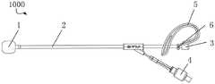
图1是本发明实施例提供的一种支撑装置的示意图;1 is a schematic diagram of a support device provided by an embodiment of the present invention;
图2是图1所示支撑装置使用时的示意图;Fig. 2 is the schematic diagram when the support device shown in Fig. 1 is in use;
图3是图1所示支撑装置的剖面图;Figure 3 is a cross-sectional view of the support device shown in Figure 1;
图4是图3所示剖面图的局部放大图;Fig. 4 is a partial enlarged view of the sectional view shown in Fig. 3;
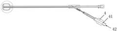
图5是本发明实施例提供的一种支撑装置在完成装配步骤S01后的示意图;5 is a schematic diagram of a support device provided by an embodiment of the present invention after completing the assembly step S01;
图6是是本发明实施例提供的一种支撑装置在完成装配步骤S02后的示意图。FIG. 6 is a schematic diagram of a support device provided by an embodiment of the present invention after completing the assembly step S02.
具体实施方式Detailed ways
为了便于理解本发明,下面结合附图和具体实施例,对本发明进行更详细的说明。需要说明的是,当元件被表述“固定于”另一个元件,它可以直接在另一个元件上、或者其间可以存在一个或多个居中的元件。当一个元件被表述“连接”另一个元件,它可以是直接连接到另一个元件、或者其间可以存在一个或多个居中的元件。本说明书所使用的术语“垂直的”、“水平的”、“左”、“右”以及类似的表述只是为了说明的目的。In order to facilitate understanding of the present invention, the present invention will be described in more detail below with reference to the accompanying drawings and specific embodiments. It should be noted that when an element is referred to as being "fixed to" another element, it can be directly on the other element, or one or more intervening elements may be present therebetween. When an element is referred to as being "connected" to another element, it can be directly connected to the other element or one or more intervening elements may be present therebetween. The terms "vertical", "horizontal", "left", "right" and similar expressions used in this specification are for illustrative purposes only.
除非另有定义,本说明书所使用的所有的技术和科学术语与属于本发明的技术领域的技术人员通常理解的含义相同。本说明书中在本发明的说明书中所使用的术语只是为了描述具体的实施例的目的,不是用于限制本发明。本说明书所使用的术语“和/或”包括一个或多个相关的所列项目的任意的和所有的组合。Unless otherwise defined, all technical and scientific terms used in this specification have the same meaning as commonly understood by one of ordinary skill in the technical field of the present invention. The terms used in the description of the present invention in this specification are only for the purpose of describing specific embodiments, and are not used to limit the present invention. As used in this specification, the term "and/or" includes any and all combinations of one or more of the associated listed items.
请参阅图1-4,支撑装置1000包括弹性球囊1和导管2。弹性球囊1套设于导管2的第一端,弹性球囊1与导管2的第一端的外壁共同围合有膨胀腔11。导管2用于支撑弹性球囊1和将膨胀腔11与外界连通,当通过导管2向膨胀腔11内注入流体时,弹性球囊1膨胀后体积变大,当通过注射通道21将膨胀腔11内流体抽出时,弹性球囊1收缩后体积变小。在进行鞍底修复时,将鞍隔b的破损处使用填充材料封堵后,将导管2套设有弹性球囊1的第一端插入蝶窦a中,通过导管2向膨胀腔11内注入流体时弹性球囊1膨胀后体积变大,弹性球囊1抵接于填充材料起支撑填充材料的作用。Referring to FIGS. 1-4 , the
在本实施例中,流体使用生理溶液,当弹性球囊1破损导致生理溶液泄露时,不会对病人造成二次伤害。In this embodiment, a physiological solution is used as the fluid, and when the
在本实施例中,弹性球囊1设置有第一通孔12,第一通孔12贯穿弹性球囊1。弹性球囊1的材料为硅胶,可以理解的是,弹性球囊1的材料还可以为塑料PVC、乳胶和TPE等材料。In this embodiment, the
在本实施例中,导管2设置有注射通道21,注射通道21的第一端设置于导管2的第一端,注射通道21的第一端设置有侧孔211。注射通道21的第二端设置于导管2的第二端,注射通道21的第二端与外界连通。导管2采用的材料为硅胶,可以理解的是,导管2的材料还可以为PVC、乳胶和TPE等材料。In this embodiment, the
在本实施例中,导管2的第一端插入第一通孔12,沿第一通孔12的轴向,弹性球囊1的两端分别与导管2的外壁密封连接,弹性球囊1与导管2的外壁围合形成膨胀腔11。侧孔211贯穿导管2的侧壁,侧孔211连通注射通道21和膨胀腔11。沿第一通孔12的轴向,导管2的第一端的端面不凸出于弹性球囊1。将导管2的第一端送入蝶窦a后,导管2的第一端的端面朝向鞍隔b的破损处,通过位于导管2的第二端的注射通道21的入口向膨胀腔11内注射流体,流体从注射通道21的第二端流向注射通道21的第一端,经侧孔211流入膨胀腔11内,使弹性球囊1膨胀体积变大,环绕在导管2的第一端的端面周围的弹性球囊1抵接于鞍隔b破损处的填充材料,以支撑填充材料,使填充材料稳固地保持在鞍隔b破损的位置,避免填充材料移位、脱落导致鞍隔b破损处再次出现缺口造成脑脊液外漏。由于导管2的第一端的端面不凸出于弹性球囊1,避免导管2的第一端的端面与填充材料干涉,导致填充材料产生位移。In this embodiment, the first end of the
进一步的,导管2还设置有分支部22和引流通道23。分支部22的第一端与导管2第二端的侧壁连接,注射通道21的第二端设置于分支部22的第二端。引流通道23的第一端设置于导管2的第一端,引流通道23的第一端与外界连通,引流通道23的第一端与外界连通的出口设置于导管2的第一端的端面。引流通道23的第二端设置于导管2的第二端,引流通道23的第二端与外界连通,引流通道23的第二端与外界连接的出口设置于导管2的第二端的端面。支撑装置1000还包括有密封盖3,密封盖3盖设于导管2的第二端的端面,以封闭引流通道23的第二端。Further, the
当弹性球囊1朝向鞍隔b的一端的端面抵接于鞍隔b破损处的填充材料时,鞍隔b破损处有脑脊液外漏,外漏的脑脊液可沿经引流通道23的第二端进入引流通道23中。通过引流通道23是否有脑脊液流出,可以判断鞍底修复的情况,若引流通道23持续有脑脊液排出,说明鞍隔b破损处仍未修复到位。When the end face of the
再进一步的,支撑装置1000还包括指示气囊4、耳挂5和套环6。指示气囊4设置有指示腔41,指示气囊4的第一端与分支部22的第二端连接,注射通道21的第二端与指示腔41连通,指示气囊4的第二端设置有第二通孔42,第二通孔42将指示腔41与外界连通。流体依次通过第二通孔42、指示腔41和注射通道21后进入膨胀腔11,由于指示腔41与膨胀腔11连通,当弹性球囊1膨胀体积变大时,指示气囊4也同时膨胀体积变大,当将流体抽出时,弹性球囊1和指示气囊4同时收缩体积变小,通过观察指示气囊4的膨胀和收缩情况,可判断弹性球囊1的膨胀和收缩情况。耳挂5的一端与导管2的第二端连接,耳挂5的第二端自耳挂5的第一端朝向导管2的第一端方向弯折后延伸得到。套环6与耳挂5的第一端连接,套环6套设于导管2的第二端,使耳挂5固定于导管2的第二端。当将导管2套设有弹性球囊1的第一端插入病人的蝶窦a中后,耳挂5可挂设于病人的一侧耳朵处。Still further, the
当进行鞍底修复时,使用填充材料封堵鞍隔b破损处后,将支撑装置1000具有弹性气囊的一端经病人鼻腔后插入蝶窦a内,此时指示气囊4位于病人鼻孔外附近,过观察指示气囊4可判断弹性气囊的膨胀和收缩情况;使用无针注射器吸取生理溶液后,将无针注射器的注射口插入第二通孔42,通过第二通孔42将生理溶液注入膨胀腔11内,以使弹性球囊1膨胀后体积变大,导管2的第一端的端面朝向鞍隔b破损处,弹性球囊1朝向鞍隔b破损处的一端的端面抵接鞍隔b破损处的填充材料,弹性球囊1环绕导管2的侧壁的侧面抵接于蝶窦a的内壁,使弹性球囊1固定在蝶窦a内;将耳挂5挂在病人的一侧耳朵上,将支撑装置1000固定,防止导管2移动造成支撑装置1000失效。在使用完成后,使用无针注射器将膨胀腔11内的生理溶液抽出,弹性气囊收缩体积变小,此时可将支撑装置1000从病人的蝶窦a中取出。When the saddle bottom is repaired, after sealing the damaged part of the septum b with a filling material, insert the end of the
在本发明实施例中,支撑装置1000包括弹性球囊1和导管2,弹性球囊1套设于导管2的第一端,弹性球囊1与导管2的第一端的外壁共同围合有膨胀腔11,导管2设置有注射通道21,注射通道21的第一端设置有侧孔211,侧孔211将与膨胀腔11和注射通道21连通,注射通道21的第二端用于与外界连通;当通过注射通道21向膨胀腔11内注入流体时,弹性球囊1膨胀后体积变大,当通过注射通道21将膨胀腔11内流体抽出时,弹性球囊1收缩后体积变小。弹性球囊1在注入流体膨胀后,将弹性球囊1与鞍隔b破损处的填充材料抵接,给予填充材料弹性支撑,避免了用于封堵鞍隔b破损处的填充材料移位导致脑脊液外漏的问题,加快了鞍隔b破损处伤口的恢复。In the embodiment of the present invention, the
本发明实施例还提供一种弹性球囊1和导管2的装配方法,应用于上述支撑装置1000,请参阅图2、图4、图5和图6,弹性球囊1和导管2的装配方法包括:The embodiment of the present invention also provides an assembling method of the
步骤S01,如图5所示,将导管2的第一端插入第一通孔12,导管2的第一端的外壁与第一通孔12的内壁密封连接。Step S01 , as shown in FIG. 5 , insert the first end of the
步骤S02,如图6所示,将第一通孔12远离导管2的孔口的边沿沿着朝向导管2的方向翻折后与导管2的外壁密封连接,以使弹性球囊1与导管2的外壁围合形成膨胀腔11。Step S02, as shown in FIG. 6 , the edge of the first through
具体的,将导管2的第一端插入第一通孔12,通过粘接的方式将导管2固定在第一通孔12内,导管2的第一端的侧壁与通孔的内壁贴合;将第一通孔12远离导管2的孔口的边沿沿着朝向导管2的方向翻折后粘接在导管2的外壁,原本弹性球囊1的外壁经过翻折后,与导管2的的一端的外壁围合形成膨胀腔11。通过上述将弹性球囊1翻折后与导管2围合形成膨胀腔11的方式,在膨胀腔11内未注入流体的状态下,可使弹性球囊1包裹依附在导管2的侧壁,在将弹性球囊1送入蝶窦a的过程中,弹性球囊1不会与周围的人体组织产生干涉;在膨胀腔11内注入流体膨胀后,弹性球囊1环绕导管2的第一端且沿着导管2的第一端朝向鞍隔b破损处的方向凸出于导管2的第一端的端面,避免了导管2的第一端凸出弹性球囊1,导管2的第一端凸出弹性球囊1的部分与鞍隔b破损处的填充材料造成填充材料移位。Specifically, the first end of the
需要说明的是,本发明的说明书及其附图中给出了本发明的较佳的实施例,但是,本发明可以通过许多不同的形式来实现,并不限于本说明书所描述的实施例,这些实施例不作为对本发明内容的额外限制,提供这些实施例的目的是使对本发明的公开内容的理解更加透彻全面。并且,上述各技术特征继续相互组合,形成未在上面列举的各种实施例,均视为本发明说明书记载的范围;进一步地,对本领域普通技术人员来说,可以根据上述说明加以改进或变换,而所有这些改进和变换都应属于本发明所附权利要求的保护范围。It should be noted that the description of the present invention and the accompanying drawings provide preferred embodiments of the present invention, however, the present invention can be implemented in many different forms, and is not limited to the embodiments described in this specification. These examples are not intended as additional limitations to the content of the present invention, and are provided for the purpose of providing a more thorough and complete understanding of the present disclosure. In addition, the above technical features continue to be combined with each other to form various embodiments not listed above, which are all regarded as the scope of the description of the present invention; further, for those of ordinary skill in the art, they can be improved or transformed according to the above description. , and all these improvements and transformations should belong to the protection scope of the appended claims of the present invention.
Claims (10)
Translated fromChinesePriority Applications (1)
| Application Number | Priority Date | Filing Date | Title |
|---|---|---|---|
| CN202210596476.0ACN114869392A (en) | 2022-05-30 | 2022-05-30 | Supporting device and assembling method |
Applications Claiming Priority (1)
| Application Number | Priority Date | Filing Date | Title |
|---|---|---|---|
| CN202210596476.0ACN114869392A (en) | 2022-05-30 | 2022-05-30 | Supporting device and assembling method |
Publications (1)
| Publication Number | Publication Date |
|---|---|
| CN114869392Atrue CN114869392A (en) | 2022-08-09 |
Family
ID=82680578
Family Applications (1)
| Application Number | Title | Priority Date | Filing Date |
|---|---|---|---|
| CN202210596476.0APendingCN114869392A (en) | 2022-05-30 | 2022-05-30 | Supporting device and assembling method |
Country Status (1)
| Country | Link |
|---|---|
| CN (1) | CN114869392A (en) |
Citations (7)
| Publication number | Priority date | Publication date | Assignee | Title |
|---|---|---|---|---|
| US20100100107A1 (en)* | 2008-10-20 | 2010-04-22 | IMDS, Inc. | Systems and methods for cerebrospinal fluid repair |
| CN203122506U (en)* | 2013-01-15 | 2013-08-14 | 北京大学第三医院 | Uterus blood stopping ball bag |
| CN104688290A (en)* | 2013-12-07 | 2015-06-10 | 复旦大学附属妇产科医院 | Method for internal compression hemostasis after minimally invasive breast lump rotary varicotomy and hemostatic balloon |
| CN109966627A (en)* | 2019-03-27 | 2019-07-05 | 深圳市擎源医疗器械有限公司 | Foley's tube |
| US20200397976A1 (en)* | 2013-02-04 | 2020-12-24 | Michael Rontal | Balloon irrigation and cleaning system for interior walls of sinus cavities |
| CN112890880A (en)* | 2019-11-19 | 2021-06-04 | 中山大学肿瘤防治中心(中山大学附属肿瘤医院、中山大学肿瘤研究所) | Supporting device for repairing skull base of four-cavity balloon |
| CN217548137U (en)* | 2022-05-30 | 2022-10-11 | 深圳市擎源医疗器械有限公司 | Supporting device |
- 2022
- 2022-05-30CNCN202210596476.0Apatent/CN114869392A/enactivePending
Patent Citations (7)
| Publication number | Priority date | Publication date | Assignee | Title |
|---|---|---|---|---|
| US20100100107A1 (en)* | 2008-10-20 | 2010-04-22 | IMDS, Inc. | Systems and methods for cerebrospinal fluid repair |
| CN203122506U (en)* | 2013-01-15 | 2013-08-14 | 北京大学第三医院 | Uterus blood stopping ball bag |
| US20200397976A1 (en)* | 2013-02-04 | 2020-12-24 | Michael Rontal | Balloon irrigation and cleaning system for interior walls of sinus cavities |
| CN104688290A (en)* | 2013-12-07 | 2015-06-10 | 复旦大学附属妇产科医院 | Method for internal compression hemostasis after minimally invasive breast lump rotary varicotomy and hemostatic balloon |
| CN109966627A (en)* | 2019-03-27 | 2019-07-05 | 深圳市擎源医疗器械有限公司 | Foley's tube |
| CN112890880A (en)* | 2019-11-19 | 2021-06-04 | 中山大学肿瘤防治中心(中山大学附属肿瘤医院、中山大学肿瘤研究所) | Supporting device for repairing skull base of four-cavity balloon |
| CN217548137U (en)* | 2022-05-30 | 2022-10-11 | 深圳市擎源医疗器械有限公司 | Supporting device |
Similar Documents
| Publication | Publication Date | Title |
|---|---|---|
| KR880002040B1 (en) | Apparatus for receiving and reinfusing blood | |
| JP3396085B2 (en) | Hollow fiber membrane type blood processor | |
| JP4002300B2 (en) | Flexible fluid junction | |
| JP2826333B2 (en) | Inflation indicator for cuffed tubing | |
| US20110184374A1 (en) | Peristaltic Pump and Cassette | |
| US9566425B2 (en) | Line, in particular a line of a blood tubing system or of a blood bag system | |
| WO2018006630A1 (en) | Breast pad, bra body, and breast pump | |
| CN211835806U (en) | External balance type hemostatic valve and catheter sheath | |
| CN114869392A (en) | Supporting device and assembling method | |
| CN217548137U (en) | Supporting device | |
| CN107206132A (en) | Gelled product for fluid collecting container | |
| WO2024149113A1 (en) | Balloon puncture device | |
| CN110786916A (en) | Ovarian Cyst Removal Leak Prevention Device | |
| CN219662583U (en) | Catheter sheath | |
| EP0300002A1 (en) | Balloon | |
| CN207980078U (en) | One and seperated multi-purpose charging electric breast pump | |
| CN113926061B (en) | Balloon catheter | |
| CN210301960U (en) | Silica gel bronchus two-chamber intubate | |
| KR200191611Y1 (en) | Endotracheal tube | |
| CN216854938U (en) | A Rat Thin Endometrial Modeling Device | |
| US6582653B1 (en) | Apparatus and method for the sterilization-in-place of intravenous bags and the like | |
| CN208838246U (en) | Intravascular stent | |
| CA1226492A (en) | Apparatus for receiving and reinfusing blood | |
| CN214762832U (en) | A connector for esophageal expansion probe | |
| JPH0423534Y2 (en) |
Legal Events
| Date | Code | Title | Description |
|---|---|---|---|
| PB01 | Publication | ||
| PB01 | Publication | ||
| SE01 | Entry into force of request for substantive examination | ||
| SE01 | Entry into force of request for substantive examination |