CN114869161A - Maintenance of base stations and cleaning of robotic systems - Google Patents
Maintenance of base stations and cleaning of robotic systemsDownload PDFInfo
- Publication number
- CN114869161A CN114869161ACN202110163517.2ACN202110163517ACN114869161ACN 114869161 ACN114869161 ACN 114869161ACN 202110163517 ACN202110163517 ACN 202110163517ACN 114869161 ACN114869161 ACN 114869161A
- Authority
- CN
- China
- Prior art keywords
- docking
- cleaning
- base
- cleaning robot
- fluid
- Prior art date
- Legal status (The legal status is an assumption and is not a legal conclusion. Google has not performed a legal analysis and makes no representation as to the accuracy of the status listed.)
- Pending
Links
- 238000004140cleaningMethods0.000titleclaimsabstractdescription279
- 238000012423maintenanceMethods0.000titleclaimsabstractdescription76
- 238000003032molecular dockingMethods0.000claimsabstractdescription226
- 239000012530fluidSubstances0.000claimsabstractdescription97
- 238000004891communicationMethods0.000claimsabstractdescription26
- 230000007246mechanismEffects0.000claimsdescription74
- XLYOFNOQVPJJNP-UHFFFAOYSA-NwaterSubstancesOXLYOFNOQVPJJNP-UHFFFAOYSA-N0.000claimsdescription46
- 230000005540biological transmissionEffects0.000claimsdescription16
- 230000001154acute effectEffects0.000claimsdescription2
- 239000008213purified waterSubstances0.000claimsdescription2
- 210000001503jointAnatomy0.000claims5
- 230000000712assemblyEffects0.000abstractdescription2
- 238000000429assemblyMethods0.000abstractdescription2
- 238000000746purificationMethods0.000description28
- 239000010865sewageSubstances0.000description16
- 238000010586diagramMethods0.000description11
- 239000007788liquidSubstances0.000description6
- 238000000034methodMethods0.000description6
- 239000000428dustSubstances0.000description5
- 238000009434installationMethods0.000description4
- 230000008569processEffects0.000description4
- 238000010408sweepingMethods0.000description3
- 230000009286beneficial effectEffects0.000description2
- 238000001514detection methodMethods0.000description2
- 239000003599detergentSubstances0.000description2
- 230000000694effectsEffects0.000description2
- 230000002093peripheral effectEffects0.000description2
- 238000011084recoveryMethods0.000description2
- 239000007787solidSubstances0.000description2
- 230000009471actionEffects0.000description1
- 238000013461designMethods0.000description1
- 239000000645desinfectantSubstances0.000description1
- 238000011161developmentMethods0.000description1
- 239000011521glassSubstances0.000description1
- 230000005484gravityEffects0.000description1
- 230000006872improvementEffects0.000description1
- 239000000463materialSubstances0.000description1
- 238000012986modificationMethods0.000description1
- 230000004048modificationEffects0.000description1
- 238000004064recyclingMethods0.000description1
- 230000002787reinforcementEffects0.000description1
- 230000004044responseEffects0.000description1
- 238000007789sealingMethods0.000description1
- 238000005406washingMethods0.000description1
- 239000002699waste materialSubstances0.000description1
Images


Classifications
- A—HUMAN NECESSITIES
- A47—FURNITURE; DOMESTIC ARTICLES OR APPLIANCES; COFFEE MILLS; SPICE MILLS; SUCTION CLEANERS IN GENERAL
- A47L—DOMESTIC WASHING OR CLEANING; SUCTION CLEANERS IN GENERAL
- A47L1/00—Cleaning windows
- A47L1/02—Power-driven machines or devices
- A—HUMAN NECESSITIES
- A47—FURNITURE; DOMESTIC ARTICLES OR APPLIANCES; COFFEE MILLS; SPICE MILLS; SUCTION CLEANERS IN GENERAL
- A47L—DOMESTIC WASHING OR CLEANING; SUCTION CLEANERS IN GENERAL
- A47L11/00—Machines for cleaning floors, carpets, furniture, walls, or wall coverings
- A47L11/24—Floor-sweeping machines, motor-driven
- A—HUMAN NECESSITIES
- A47—FURNITURE; DOMESTIC ARTICLES OR APPLIANCES; COFFEE MILLS; SPICE MILLS; SUCTION CLEANERS IN GENERAL
- A47L—DOMESTIC WASHING OR CLEANING; SUCTION CLEANERS IN GENERAL
- A47L11/00—Machines for cleaning floors, carpets, furniture, walls, or wall coverings
- A47L11/28—Floor-scrubbing machines, motor-driven
- A—HUMAN NECESSITIES
- A47—FURNITURE; DOMESTIC ARTICLES OR APPLIANCES; COFFEE MILLS; SPICE MILLS; SUCTION CLEANERS IN GENERAL
- A47L—DOMESTIC WASHING OR CLEANING; SUCTION CLEANERS IN GENERAL
- A47L11/00—Machines for cleaning floors, carpets, furniture, walls, or wall coverings
- A47L11/40—Parts or details of machines not provided for in groups A47L11/02 - A47L11/38, or not restricted to one of these groups, e.g. handles, arrangements of switches, skirts, buffers, levers
- A47L11/4013—Contaminants collecting devices, i.e. hoppers, tanks or the like
- A47L11/4025—Means for emptying
- A—HUMAN NECESSITIES
- A47—FURNITURE; DOMESTIC ARTICLES OR APPLIANCES; COFFEE MILLS; SPICE MILLS; SUCTION CLEANERS IN GENERAL
- A47L—DOMESTIC WASHING OR CLEANING; SUCTION CLEANERS IN GENERAL
- A47L11/00—Machines for cleaning floors, carpets, furniture, walls, or wall coverings
- A47L11/40—Parts or details of machines not provided for in groups A47L11/02 - A47L11/38, or not restricted to one of these groups, e.g. handles, arrangements of switches, skirts, buffers, levers
- A47L11/4091—Storing or parking devices, arrangements therefor; Means allowing transport of the machine when it is not being used
- A—HUMAN NECESSITIES
- A47—FURNITURE; DOMESTIC ARTICLES OR APPLIANCES; COFFEE MILLS; SPICE MILLS; SUCTION CLEANERS IN GENERAL
- A47L—DOMESTIC WASHING OR CLEANING; SUCTION CLEANERS IN GENERAL
- A47L2201/00—Robotic cleaning machines, i.e. with automatic control of the travelling movement or the cleaning operation
- A47L2201/02—Docking stations; Docking operations
- A47L2201/024—Emptying dust or waste liquid containers
- A—HUMAN NECESSITIES
- A47—FURNITURE; DOMESTIC ARTICLES OR APPLIANCES; COFFEE MILLS; SPICE MILLS; SUCTION CLEANERS IN GENERAL
- A47L—DOMESTIC WASHING OR CLEANING; SUCTION CLEANERS IN GENERAL
- A47L2201/00—Robotic cleaning machines, i.e. with automatic control of the travelling movement or the cleaning operation
- A47L2201/02—Docking stations; Docking operations
- A47L2201/026—Refilling cleaning liquid containers
Landscapes
- Manipulator (AREA)
Abstract
Translated fromChinese
Description
Translated fromChinese技术领域technical field
本申请涉及清洁设备领域,具体涉及一种维护基站以及清洁机器人系统。The present application relates to the field of cleaning equipment, in particular to a maintenance base station and a cleaning robot system.
背景技术Background technique
随着经济的发展和生活水平的提高,各种各样的清洁机器人广泛应用于家庭清洁任务中,比如扫地机器人、洗地机器人或擦玻璃机器人等。通常清洁机器人包括清洁容器组件,用于分开接收清洁机器人在清洁过程中所收集的灰尘、垃圾碎屑或污水等中的一种或多种,但是,由于缺少对清洁机器人的清洁容器组件的必要维护,容易影响清洁机器人的正常工作性能。With the development of the economy and the improvement of living standards, various cleaning robots are widely used in household cleaning tasks, such as sweeping robots, floor washing robots or glass cleaning robots. Usually the cleaning robot includes a cleaning container assembly for separately receiving one or more of the dust, garbage debris or sewage collected by the cleaning robot during the cleaning process. However, due to the lack of the need for the cleaning container assembly of the cleaning robot Maintenance can easily affect the normal working performance of the cleaning robot.
发明内容SUMMARY OF THE INVENTION
本申请实施例提供一种维护基站以及清洁机器人系统,以解决目前清洁机器人的清洁容器组件缺少必要维护的技术问题。Embodiments of the present application provide a maintenance base station and a cleaning robot system to solve the technical problem that the cleaning container assembly of the current cleaning robot lacks necessary maintenance.
本申请实施例提供一种维护基站,所述维护基站用于与清洁机器人配合,所述清洁机器人包括清洁容器组件和与所述清洁容器组件气动连通的对接阀,所述维护基站包括基座、至少一个清洁箱、对接装置和至少一个流体驱动装置,所述至少一个清洁箱、所述对接装置和所述至少一个流体驱动装置均安装于所述基座上,所述对接装置通过管道与所述至少一个清洁箱气动连通,所述对接装置用于与所述清洁机器人的对接阀对接,以建立连通所述清洁容器组件和所述至少一个清洁箱的流体通道,所述至少一个流体驱动装置分别与所述至少一个清洁箱一一对应,每一所述流体驱动装置用于驱动流体从对应的清洁箱通过所述流体通道流向所述清洁机器人的清洁容器组件,或者用于驱动流体从所述清洁机器人的清洁容器组件通过所述流体通道流向对应的清洁箱。An embodiment of the present application provides a maintenance base station, the maintenance base station is configured to cooperate with a cleaning robot, the cleaning robot includes a cleaning container assembly and a docking valve in pneumatic communication with the cleaning container assembly, and the maintenance base station includes a base, At least one cleaning box, a docking device and at least one fluid drive device, all of which are mounted on the base, the docking device being connected to the base via a pipe. The at least one cleaning box is in pneumatic communication, the docking device is used for docking with a docking valve of the cleaning robot to establish a fluid channel connecting the cleaning container assembly and the at least one cleaning box, and the at least one fluid driving device There is a one-to-one correspondence with the at least one cleaning box, and each of the fluid driving devices is used for driving the fluid from the corresponding cleaning box to flow to the cleaning container assembly of the cleaning robot through the fluid channel, or for driving the fluid from the corresponding cleaning box to the cleaning container assembly of the cleaning robot. The cleaning container assembly of the cleaning robot flows to the corresponding cleaning box through the fluid channel.
本申请实施例还提供一种清洁机器人系统,所述清洁机器人系统包括清洁机器人和如上所述的维护基站。Embodiments of the present application further provide a cleaning robot system, where the cleaning robot system includes a cleaning robot and the maintenance base station as described above.
区别于现有技术,本申请实施例提供一种维护基站以及清洁机器人系统,通过所述维护基站包括基座、至少一个清洁箱、对接装置和至少一个流体驱动装置,所述对接装置用于与所述清洁机器人的对接阀对接,从而可以建立连通所述清洁容器组件和所述至少一个清洁箱的流体通道,又通过所述至少一个流体驱动装置分别与所述至少一个清洁箱一一对应,每一所述流体驱动装置用于驱动流体从对应的清洁箱通过所述流体通道流向所述清洁机器人的清洁容器组件,或者用于驱动流体从所述清洁机器人的清洁容器组件通过所述流体通道流向对应的清洁箱,从而可以实现对所述清洁机器人的清洁容器组件进行维护,避免出现垃圾滞留时间过长或清洁介质耗尽的情况,使得所述清洁机器人可以在维护之后持续工作。Different from the prior art, an embodiment of the present application provides a maintenance base station and a cleaning robot system. The maintenance base station includes a base, at least one cleaning box, a docking device, and at least one fluid driving device, and the docking device is used for The docking valve of the cleaning robot is docked, so that a fluid channel connecting the cleaning container assembly and the at least one cleaning box can be established, and the at least one fluid driving device is in a one-to-one correspondence with the at least one cleaning box, respectively, Each of the fluid drive devices is used to drive fluid from the corresponding cleaning box through the fluid channel to the cleaning container assembly of the cleaning robot, or to drive fluid from the cleaning container assembly of the cleaning robot through the fluid channel Flow to the corresponding cleaning box, so that the cleaning container assembly of the cleaning robot can be maintained, and the situation that the garbage stays for too long or the cleaning medium is exhausted can be avoided, so that the cleaning robot can continue to work after maintenance.
附图说明Description of drawings
一个或多个实施例通过与之对应的附图中的图片进行示例性说明,这些示例性说明并不构成对实施例的限定,附图中具有相同参考数字标号的元件表示为类似的元件,除非有特别申明,附图中的图不构成比例限制。One or more embodiments are exemplified by the pictures in the corresponding drawings, and these exemplifications do not constitute limitations of the embodiments, and elements with the same reference numerals in the drawings are denoted as similar elements, Unless otherwise stated, the figures in the accompanying drawings do not constitute a scale limitation.
图1是本申请实施例提供的一种清洁机器人系统的结构示意图一(对接装置相对基座收缩状态);1 is a schematic structural diagram 1 of a cleaning robot system provided by an embodiment of the present application (the docking device is in a retracted state relative to the base);
图2是本申请实施例提供的一种清洁机器人系统的结构示意图二(对接装置伸展相对基座伸展状态);2 is a second structural schematic diagram of a cleaning robot system provided by an embodiment of the present application (the docking device is extended relative to the base extended state);
图3是图1提供的清洁机器人的结构示意图;Fig. 3 is the structural representation of the cleaning robot provided by Fig. 1;
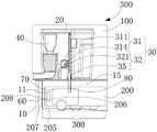
图4是图1提供的维护基站的截面结构示意图一;FIG. 4 is a schematic diagram 1 of a cross-sectional structure of the maintenance base station provided in FIG. 1;
图5是本申请实施例提供的一种清洁机器人系统的结构示意图三(对接装置相对基座收缩状态);5 is a schematic structural diagram 3 of a cleaning robot system provided by an embodiment of the present application (the docking device is in a retracted state relative to the base);
图6是本申请实施例提供的一种清洁机器人系统的结构示意图四(对接装置伸展相对基座伸展状态);FIG. 6 is a schematic structural diagram 4 of a cleaning robot system provided by an embodiment of the present application (the docking device is extended relative to the base extended state);
图7是本申请实施例提供的一种清洁机器人系统和基座的俯视示意图;7 is a schematic top view of a cleaning robot system and a base provided by an embodiment of the present application;
图8是本申请实施例提供的一种清洁机器人系统的结构示意图五(对接装置伸展相对基座伸展状态);8 is a schematic structural diagram 5 of a cleaning robot system provided by an embodiment of the present application (the docking device is extended relative to the base extended state);
图9是图1提供的维护基站的截面结构示意图二;FIG. 9 is a second schematic diagram of the cross-sectional structure of the maintenance base station provided in FIG. 1;
图10是申请实施例提供的另一种维护基站的截面结构示意图;10 is a schematic cross-sectional structural diagram of another maintenance base station provided by an embodiment of the application;
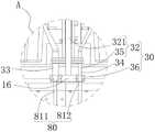
图11是图2中A处放大示意图;Fig. 11 is the enlarged schematic diagram at A in Fig. 2;
图12是图1提供的维护基站的对接装置的分解示意图;FIG. 12 is an exploded schematic diagram of the docking device for the maintenance base station provided in FIG. 1;
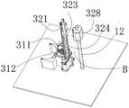
图13是图12中B处放大示意图。FIG. 13 is an enlarged schematic view of B in FIG. 12 .
具体实施方式Detailed ways
为了使本申请的目的、技术方案及优点更加清楚明白,以下结合附图及实施例,对本申请进行进一步详细说明。应当理解,此处所描述的具体实施例仅用以解释本申请,并不用于限定本申请。基于本申请中的实施例,本领域普通技术人员在没有作出创造性劳动前提下所获得的所有其他实施例,都属于本申请保护的范围。In order to make the purpose, technical solutions and advantages of the present application more clearly understood, the present application will be described in further detail below with reference to the accompanying drawings and embodiments. It should be understood that the specific embodiments described herein are only used to explain the present application, but not to limit the present application. Based on the embodiments in the present application, all other embodiments obtained by those of ordinary skill in the art without creative work fall within the protection scope of the present application.
需要说明的是,如果不冲突,本申请实施例中的各个特征可以相互结合,均在本申请的保护范围之内。另外,虽然在装置示意图中进行了功能模块划分,在流程图中示出了逻辑顺序,但是在某些情况下,可以以不同于装置中的模块划分,或流程图中的顺序执行所示出或描述的步骤。再者,本申请所采用的“第一”、“第二”、“第三”等字样并不对数据和执行次序进行限定,仅是对功能和作用基本相同的相同项或相似项进行区分。It should be noted that, if there is no conflict, various features in the embodiments of the present application may be combined with each other, which are all within the protection scope of the present application. In addition, although the functional modules are divided in the schematic diagram of the device, and the logical sequence is shown in the flowchart, in some cases, the modules in the device may be divided differently, or the sequence shown in the flowchart may be performed. or the described steps. Furthermore, the words "first", "second" and "third" used in this application do not limit the data and execution order, but only distinguish the same or similar items with basically the same function and effect.
请参阅图1和图2,本申请实施例提供一种清洁机器人系统300,所述清洁机器人系统300包括清洁机器人200和维护基站100。Referring to FIGS. 1 and 2 , an embodiment of the present application provides a
对于本申请实施例提供的清洁机器人200,可以理解的是,所述清洁机器人200可以是扫地机器人、扫拖一体机器人、洗地机器人或擦地机器人等其中任意一种。For the
所述清洁机器人200包括机器人主体201和可拆卸连接于所述机器人主体201的清洁容器组件70、以及与所述清洁容器组件70气动连通的对接阀80。所述清洁容器组件70用于分开接收清洁机器人200在清洁过程中所收集的灰尘、垃圾碎屑或污水等中的一种或多种。所述清洁容器组件70可以包括至少一个容器。其中,所述至少一个容器可以包括净水容器71和集污容器72,所述净水容器71用于存储清水或洗涤剂,所述集污容器72用于存储垃圾碎屑或者用于存储污水。其中,所述净水容器71和所述集污容器72可以一体设置,或者,所述净水容器71和所述集污容器72也可以组装形成一个整体,或者,所述净水容器71和所述集污容器72也可以为两个相互独立的部件。在其他实施方式中,所述至少一个容器可以包括净水容器71,但不包括集污容器72;或者,所述至少一个容器可以包括集污容器72,但不包括净水容器71。The
所述对接阀80包括至少一个对接端口81,所述对接端口81的结构形式不限,例如,所述对接端口81可以为设置有单向阀的端口,也可以为设置有可活动盖板的端口,可以防止所述清洁容器组件70内的灰尘碎屑或液体泄漏。所述对接端口81的数量可以根据实际需要自行设置,例如,所述对接端口81的数量可以为一个,用于与净水容器71或集污容器72气动连通,从而方便维护基站100通过所述对接端口81对净水容器71提供补给维护,或者对集污容器72提供脏污回收维护;或者,所述对接端口81的数量也可以为一个以上,所述至少一个对接端口81可以包括第一对接端口811和第二对接端口812,所述第一对接端口811与所述净水容器71气动连通,所述第二对接端口812与所述集污容器72气动连通,从而维护基站100可以通过所述第一对接端口811和所述第二对接端口812分别对所述净水容器71和所述集污容器72提供维护。The
所述机器人主体201为所述清洁机器人200的主体部分,所述机器人主体201可以呈圆形、矩形或D形等任意一种形状,在此不作限定。在一可选实施例中,机器人主体201也可以是其他设计构造,例如,机器人主体201为一体成型结构、左右分离设置的结构,本申请实施例对本体的材料、形状、结构等不做限定。The robot
所述机器人主体201可以包括底盘和上盖组件,上盖组件可拆卸地安装于底盘上,以在使用期间保护清洁机器人200内部的各种功能部件免受激烈撞击或无意间滴洒的液体的损坏;底盘和/或上盖组件用于承载和支撑各种功能部件。所述上盖组件背离所述底盘的表面形成外观面,可以提升所述清洁机器人200的整体外观,外观面上可以设置按键,方便用户通过按键操作所述清洁机器人200。所述底盘和所述上盖组件之间形成所述安装腔,所述安装腔用于为所述清洁机器人200的内部器件提供排布空间。所述清洁机器人200可以在所述安装腔中排布真空泵、电路板、地面检测传感器、碰撞检测传感器和沿墙传感器等。The
请继续参阅图3,所述清洁机器人200包括安装于所述底盘上的行走机构202,所述行走机构202包括一对行走轮203、至少一个万向轮204、以及用于带动轮子转动的马达,所述一对行走轮203和所述至少一个万向轮204至少部分凸伸出所述底盘的底部,例如,在清洁机器人200在自身重量的作用下,所述一对行走轮203可以部分地隐藏于底盘内。在一可选实施例中,所述行走机构202还可以包括三角履带轮、麦克纳姆轮等中的任意一种。所述行走机构202也可以不包括所述至少一个万向轮204。Please continue to refer to FIG. 3 , the
所述清洁机器人200可以被设计成自主地在地面上规划路径,也可以被设计成响应于遥控指令在地面上移动。所述清洁机器人200可以通过陀螺仪、加速度计、摄像头、GPS定位和/或激光雷达等其中一种或几种的组合进行导航,例如,所述清洁机器人200可以在顶面凸出设置激光雷达,通过激光雷达对周围环境进行扫描采集障碍物数据,根据障碍物数据建立环境地图,可以根据环境地图进行实时定位,便于规划清洁路径。The cleaning
所述清洁机器人200可以自主地导航至维护基站100,使得所述清洁机器人200与维护基站100完成对接,以方便所述维护基站100对所述清洁机器人200进行维护。The cleaning
对于本申请实施例提供的维护基站100,所述维护基站100用于对所述清洁机器人200进行维护,所述维护基站100可以对所述清洁机器人200执行充电、清洁介质补给、污水回收或清洁垃圾回收等其中任意一种或多种的维护。For the
请参阅继续图1和图2,所述维护基站100包括基座10、至少一个清洁箱20、对接装置30和至少一个流体驱动装置40。所述至少一个清洁箱20、所述对接装置30和所述至少一个流体驱动装置40均安装于所述基座10上,所述对接装置30通过管道与所述至少一个清洁箱20气动连通,所述对接装置30用于与所述清洁机器人200的对接阀80对接,以建立连通所述清洁容器组件70和所述至少一个清洁箱20的流体通道50。所述至少一个流体驱动装置40分别与所述至少一个清洁箱20一一对应,每一所述流体驱动装置40用于驱动流体从对应的清洁箱20通过所述流体通道50流向所述清洁机器人200的清洁容器组件70,或者用于驱动流体从所述清洁机器人200的清洁容器组件70通过所述流体通道50流向对应的清洁箱20。1 and 2 , the
区别于现有技术,本申请实施例提供一种维护基站100以及清洁机器人系统300,通过所述维护基站100包括基座10、至少一个清洁箱20、对接装置30和至少一个流体驱动装置40,所述对接装置30用于与所述清洁机器人200的对接阀80对接,从而可以建立连通所述清洁容器组件70和所述至少一个清洁箱20的流体通道50,又通过所述至少一个流体驱动装置40分别与所述至少一个清洁箱20一一对应,每一所述流体驱动装置40用于驱动流体从对应的清洁箱20通过所述流体通道50流向所述清洁机器人200的清洁容器组件70,或者用于驱动流体从所述清洁机器人200的清洁容器组件70通过所述流体通道50流向对应的清洁箱20,从而可以实现对所述清洁机器人200的清洁容器组件70进行维护,避免出现垃圾滞留时间过长或清洁介质耗尽的情况,使得所述清洁机器人200可以在维护之后持续工作。Different from the prior art, the embodiment of the present application provides a
在本实施方式中,所述维护基站100可以实现分别对所述清洁机器人200的净水容器71和集污容器72提供维护。所述清洁机器人200可以自主地导航至清洁基站,使得所述清洁机器人200的对接阀80与维护基站100的对接装置30完成对接,以方便所述维护基站100对所述清洁机器人200进行维护。In this embodiment, the
所述至少一个清洁箱20包括净水箱21和集污箱22。所述对接装置30包括第一对接部33和第二对接部34,所述第一对接部33通过第一柔性管与所述集污箱22气动连通,所述第一对接部33用于与所述对接阀80的第一对接端口811对接连通,以建立连通所述净水容器71和所述净水箱21之间的流体通道50;所述第二对接部34通过第二柔性管与所述净水箱21气动连通,所述第二对接部34用于与所述对接阀80的第二对接端口812对接连通,以建立连通所述集污容器72和所述集污箱22之间的流体通道50。所述至少一个流体驱动装置40包括第一流体驱动装置41和第二流体驱动装置42,所述第一流体驱动装置41用于驱动所述净水箱21内的流体通过所述第一对接部33而流向所述清洁机器人200的净水容器71,所述第二流体驱动装置42用于驱动所述清洁机器人200的集污容器72内的流体通过所述第二对接部34而流向所述集污箱22。The at least one
其中,所述净水箱21可以存储清水或洗涤剂或消毒剂等任意一种清洁介质,通过所述第一流体驱动装置41用于驱动所述净水箱21内的流体通过所述第一对接部33而流向所述清洁机器人200的净水容器71,可以及时补充所述净水箱21内的清洁介质,从而实现清洁介质的自动补给,使得所述清洁机器人200能够继续应用清洁介质于清洁地面,有利于提高清洁效果。Wherein, the
所述集污箱22可以是集尘箱,所述集污箱22可以收集灰尘碎屑,或者,所述集污箱22也可以为污水回收箱,所述集污箱22可以收集污水,通过所述第二流体驱动装置42用于驱动所述清洁机器人200的集污容器72内的流体通过所述第二对接部34而流向所述集污箱22,可以充分排空所述集污箱22内的脏污,避免脏污滞留在所述集污箱22中而发霉发臭,同时提高清洁机器人200的持续清洁能力。The
所述流体驱动装置40可以是水泵、气泵或风机等其中任意一种。The
所述第一流体驱动装置41可以是气泵或水泵,当所述第一流体驱动装置41是气泵时,所述第一流体驱动装置41与所述净水箱21的内腔气动连通,所述第一流体驱动装置41可以增加所述净水箱21内液面上方的气压,以将所述净水箱21内的液体传输至所述对接装置30而进入所述清洁机器人200;当所述第一流体驱动装置41是水泵时,所述第一流体驱动装置41可以连通在所述净水箱21和所述对接装置30之间,以将所述净水箱21内的液体传输至所述对接装置30而进入所述清洁机器人200。The first
所述第二流体驱动装置42可以是风机或水泵,当所述第二流体驱动装置42是气泵时,所述第二流体驱动装置42与所述集污箱22的内腔气动连通,所述第二流体驱动装置42可以在所述集污箱22内腔中产生负压,以产生吸力将所述清洁机器人200所存储的脏污抽吸至所述集污箱22内;当所述第一流体驱动装置41是水泵时,所述第二流体驱动装置42可以连通在所述集污箱22和所述对接装置30之间,以将所述清洁机器人200所存储的脏污抽吸至所述集污箱22内。The second
在其他实施方式中,所述维护基站100仅对所述清洁机器人200的净水容器71提供维护,则相应的,所述对接装置30用于与所述清洁机器人200的净水容器71对接并气动连通;或者,所述维护基站100仅对所述清洁机器人200的集污容器72提供维护,则相应的,所述对接装置30用于与所述清洁机器人200的集污容器72对接并气动连通。In other embodiments, the
请继续参阅图4、图5和图6,在本实施方式中,所述基座10为所述维护基站100的主体部分,所述基座10可以为所述清洁机器人200提供承载作用,并为所述至少一个清洁箱20、所述对接装置30和所述至少一个流体驱动装置40提供安装空间。所述基座10上可以设置充电组件11,以通过所述充电组件11对所述清洁机器人200进行充电。所述至少一个清洁箱20可以与所述基座10可拆卸连接,从而方便将所述至少一个清洁箱20取出,以便于对所述至少一个清洁箱20的维护,方便进行更换清洁介质或清空脏污等操作。在其他实施方式中,所述至少一个清洁箱20也可以不可拆卸地固定于所述基座10。Please continue to refer to FIG. 4 , FIG. 5 and FIG. 6 , in this embodiment, the
请继续参阅图4、图5和图6,进一步地,所述对接装置30包括驱动组件31和传动连接所述驱动组件31的对接机构32,所述驱动组件31安装于所述基座10上,所述对接机构32可伸缩地连接于所述基座10,所述对接机构32通过管道与所述至少一个清洁箱20气动连通,所述驱动组件31可驱动所述对接机构32相对所述基座10伸展而与所述清洁机器人200对接,或相对所述基座10收缩而与所述清洁机器人200分离。Please continue to refer to FIG. 4 , FIG. 5 and FIG. 6 , further, the
在本实施方式中,所述驱动组件31包括驱动电机311和传动机构314。所述驱动电机311安装于所述基座10上。所述传动机构314传动连接所述驱动电机311和所述对接机构32,所述驱动电机311可以通过所述传动机构314驱动所述对接机构32相对所述基座10伸缩移动。In this embodiment, the
其中,所述传动机构314可以包括一个或多个传动齿轮、螺杆或连杆等其中任意一种或多种的组合。Wherein, the
当所述维护基站100检测到所述清洁机器人200移动至预设对位区域300,所述驱动电机311可以驱动所述对接机构32相对所述基座10伸展,所述驱动电机311可以调节所述对接机构32的伸展位置,保证所述对接机构32移动至与所述清洁机器人200的对接阀80紧密接合的位置,可以有效防止所述对接机构32与所述清洁机器人200的对接阀80的接合处密封程度不足而导致泄漏;在维护基站100完成基本维护工作之后,所述驱动电机311可以驱动所述对接机构32相对所述基座10收缩,以使得所述对接机构32与所述清洁机器人200的对接阀80相互分离,可以避免所述对接机构32妨碍所述清洁机器人200退出所述维护基站100。When the
请继续参阅图4、图5和图6,在一些实施方式中,所述基座10在预设对位区域300设有充电组件11,所述维护基站100还包括主控制板60,所述主控制板60电连接所述充电组件11和所述驱动组件31,当所述清洁机器人200到达所述基座10的预设对位区域300上并与所述充电组件11对接时,所述充电组件11向所述主控制板60发送充电信号,所述主控制板60根据所述充电信号控制所述驱动组件31驱动所述对接机构32可相对所述基座10伸展至预设位置以与所述清洁机器人200的对接阀80对接。Please continue to refer to FIG. 4 , FIG. 5 and FIG. 6 , in some embodiments, the
其中,所述清洁机器人200设置有第一充电极片205和电连接所述第一充电极片205的可充电电池206,所述第一充电极片205可以设置在所述清洁机器人200的侧面或底面,所述充电组件11包括第二充电极片207和电连接所述第二充电极片207和所述主控制板60的电源转换器208,所述第二充电极片207在所述基座10上的位置对应所述第一充电极片205的位置设置,所述第一充电极片205可与所述第二充电极片207对接建立电性连接,所述第二充电极片207处的充电信号可反馈至所述主控制板60。当所述清洁机器人200在预设对位区域300成功与所述充电组件11对接进行充电时,可以理解的是,所述清洁机器人200的对接阀80也正好位于对准所述对接机构32的位置,从而无需额外的传感器,通过借助充电信号可以准确判断控制所述对接机构32与所述对接阀80进行结合的时机,这种方式简单准确,有利于节省复杂的对位传感器硬件并降低产品成本。The cleaning
在其他实施方式中,所述对接机构32也可以固定在所述基座10上,通过所述清洁机器人200移动至预设对位区域300,主动与所述对接机构32对接。In other embodiments, the
请继续参阅图4、图5和图6,进一步地,所述对接机构32的伸缩方向平行于所述基座10的高度方向,或者,所述对接机构32的伸缩方向与所述基座10的高度方向呈锐角设置。Please continue to refer to FIG. 4 , FIG. 5 and FIG. 6 , further, the telescopic direction of the
在本实施方式中,所述对接机构32大致在所述基座10高度方向上进行伸缩,则所述对接机构32主要占用所述基座10的高度方向上的空间进行活动,有利于避免所述对接机构32过多占用所述维护基站100的横向尺寸。In the present embodiment, the
以所述基座10所在地面为参考基准,所述对接机构32的初始位置可以在所述基座10的第一预设高度,所述对接机构32可相对所述基座10伸展至第二预设高度,其中,所述第二预设高度小于所述第一预设高度,即所述对接机构32在伸展过程中相对所述基座10下降,所述对接机构32最终可以抵接在所述清洁机器人200的顶部,可以通过所述对接机构32对所述清洁机器人200的抵压力实现锁定所述清洁机器人200,避免所述清洁机器人200在维护过程中位置漂移;或者,所述第二预设高度大于所述第一预设高度,即所述对接机构32在伸展过程中相对所述基座10上升,所述对接机构32最终可以抵接在所述清洁机器人200的底部,从而所述清洁容器组件70的流体或固体可以在重力作用下自然进入所述对接机构32。Taking the ground of the base 10 as a reference, the initial position of the
在其他实施方式中,所述对接机构32的伸缩方向垂直于所述基座10的高度方向,或者所述对接机构32的伸缩方向相对所述基座10的水平方向倾斜设置。In other embodiments, the telescopic direction of the
请继续参阅图4、图5和图6,进一步地,所述基座10包括底座13和固定连接所述底座13的主壳体14,所述底座13用于承载所述清洁机器人200,所述主壳体14和所述底座13围合形成有收容腔15,所述收容腔15用于接收所述清洁机器人200,所述至少一个清洁箱20、所述对接装置30和所述至少一个流体驱动装置40均安装于所述主壳体14上,所述对接装置30布置在所述收容腔15背离所述底座13一侧。Please continue to refer to FIG. 4 , FIG. 5 and FIG. 6 , further, the
在本实施方式中,所述主壳体14固定于所述底座13的上侧,所述底座13放置于地面上,所述主壳体14连接于所述底座13背离地面一侧。所述主壳体14为中空壳体,所述至少一个清洁箱20和所述至少一个流体驱动装置40收容于所述主壳体14的内腔中。所述主壳体14设有连通所述收容腔15的开口,所述开口布置在所述收容腔15背离所述底座13一侧,所述对接机构32经所述开口收缩于所述主壳体14的内腔中,所述对接机构32也可以经所述开口伸入所述收容腔15内,所述对接机构32最终可以抵接在所述清洁机器人200的顶部,可以通过所述对接机构32对所述清洁机器人200的抵压力实现锁定所述清洁机器人200,避免所述清洁机器人200在维护过程中位置漂移。In this embodiment, the
请继续参阅图4、图5、图6和图7,进一步地,所述底座13邻近所述对接装置30一侧的表面凹设有一对定位槽16,所述一对定位槽16用于分别与所述清洁机器人200的一对行走轮203定位配合。在本实施方式中,所述一对定位槽16分别布置于所述底座13的左右两侧,所述一对定位槽16位于预设对位区域300内。所述一对定位槽16分别与所述清洁机器人200的一对行走轮203相匹配,当所述清洁机器人200移动至所述底座13上时,所述清洁机器人200的一对行走轮203可分别定位于所述底座13上的一对定位槽16内,可以保证所述清洁机器人200定位在预设对位区域300内,从而方便所述对接机构32与所述清洁机器人200进行稳定对接。Please continue to refer to FIG. 4 , FIG. 5 , FIG. 6 and FIG. 7 , further, a pair of
请继续参阅图4、图5、图6和图7,进一步地,所述对接机构32正对所述一对定位槽16之间的中心线,且所述对接机构32与所述一对定位槽16在水平方向上的距离d小于所述清洁机器人200的宽度D的四分之一。从而所述对接机构32与所述清洁机器人200的对接处较为接近所述清洁机器人200的中心位置,可以避免所述清洁机器人200因前端部分或后端部分受到所述对接机构抵压而翘起的情况。Please continue to refer to FIG. 4 , FIG. 5 , FIG. 6 and FIG. 7 , further, the
请参阅图6和图8,进一步地,所述对接机构32可相对所述基座10伸展至预设位置,所述对接机构32在预设位置抵触于所述清洁机器人200的上表面,或者,所述对接机构32在预设位置伸入所述清洁机器人200的清洁容器组件70内。Please refer to FIG. 6 and FIG. 8 , further, the
请参阅图6,一种实施方式中,所述对接机构32可相对所述基座10伸展至预设位置,所述对接机构32在预设位置抵触于所述清洁机器人200的上表面。在本实施方式中,所述清洁机器人200在上表面设置有所述对接阀80,所述对接阀80可以通过管道连通所述清洁容器组件70,连通所述对接阀80的管道一端延伸至所述清洁容器组件70的底部,从而方便通过所述对接阀80和对应的管道排空所述清洁容器组件70内的液体或固体。Referring to FIG. 6 , in one embodiment, the
请参阅图8,另一种实施方式中,所述对接机构32在预设位置至少部分伸入所述清洁机器人200的清洁容器组件70内。在本实施方式中,所述对接机构32伸入所述清洁机器人200的清洁容器组件70内,从而即使流体从所述对接机构32与所述清洁机器人200的接合处泄漏也能完全回流至所述清洁容器组件70内,避免流体泄漏至所述清洁机器人200的表面或者维护基站的内部。Referring to FIG. 8 , in another embodiment, the
请参阅图9,进一步地,所述对接机构32包括伸缩架321和固定连接所述伸缩架321的至少一个对接部35,所述伸缩架321滑动连接所述基座10,所述驱动组件31驱动所述伸缩架321相对所述基座10滑动伸缩,所述至少一个对接部35可随所述伸缩架321活动而相对所述基座10伸缩。Referring to FIG. 9 , further, the
在本实施方式中,所述驱动组件31包括驱动电机311和传动连接所述驱动电机311的传动齿轮312,所述伸缩架321设有齿条结构322,所述齿条结构322沿所述伸缩架321相对所述基座10滑动方向延伸,所述齿条结构322与所述传动齿轮312相啮合,所述驱动电机311可驱动所述传动齿轮312转动,进而经所述齿条结构322带动所述伸缩架321相对所述基座10滑动。例如,所述驱动电机311可驱动所述传动齿轮312沿第一预设方向转动,进而经所述齿条结构322带动所述伸缩架321相对所述基座10伸展;所述驱动电机311可驱动所述传动齿轮312沿第二预设方向转动,进而经所述齿条结构322带动所述伸缩架321相对所述基座10收缩,其中,第一预设方向和第二预设方向相反。In this embodiment, the
所述伸缩架321呈长条状,所述伸缩架321的长度方向平行于所述伸缩架321相对所述基座10的滑动方向。所述齿条结构322沿所述伸缩架321的长度方向延伸。所述至少一个对接部35连接于所述伸缩架321的端部。所述对接部35的数量可以是一个或一个以上,本领域的技术人员可以根据实际需要进行设置。The
请参阅图10,在其他实施方式中,所述驱动组件31的结构形式并不局限于上述举例,例如,所述驱动组件31包括驱动电机311和传动连接所述驱动电机311的螺杆313,所述螺杆313的长度方向平行于所述伸缩架321的滑动方向,所述伸缩架321设有与所述螺杆313螺接的螺纹连接部327,所述驱动电机311可驱动所述螺杆313转动,进而通过所述螺纹连接部327带动所述伸缩架321相对所述基座10滑动。Referring to FIG. 10 , in other embodiments, the structure of the
请参阅图2和图11,进一步地,所述对接阀80包括与所述清洁容器组件70气动连通的至少一个对接端口81,所述对接装置30包括至少一个对接部35和固定连接所述至少一个对接部35的定位件36,所述至少一个对接部35分别与所述至少一个清洁箱20一一对应并气动连通,所述定位件36用于与所述清洁机器人200对接并定位配合,以使得所述至少一个对接部35分别对准所述清洁机器人200的至少一个对接端口81。Please refer to FIGS. 2 and 11 , further, the
在本实施方式中,所述对接阀80包括第一对接端口811和第二对接端口812。所述第一对接端口811与所述净水容器71气动连通。所述第二对接端口812与所述集污容器72气动连通。所述至少一个对接部35包括第一对接部33和第二对接部34,所述第一对接部33通过管道与所述集污箱22气动连通,所述第一对接部33用于与所述对接阀80的第一对接端口811对接连通,以建立连通所述净水容器71和所述净水箱21之间的流体通道50;所述第二对接部34通过管道与所述净水箱21气动连通,所述第二对接部34用于与所述对接阀80的第二对接端口812对接连通,以建立连通所述集污容器72和所述集污箱22之间的流体通道50。所述第一流体驱动装置41用于驱动所述净水箱21内的流体通过所述第一对接部33而流向所述清洁机器人200的净水容器71,所述第二流体驱动装置42用于驱动所述清洁机器人200的集污容器72内的流体通过所述第二对接部34而流向所述集污箱22。In this embodiment, the
所述清洁机器人200在外表面凹设有定位槽16,所述第一对接端口811设置于所述定位槽16所在区域内,所述第二对接端口812设置于所述定位槽16所在区域内。所述定位件36用于与所述定位槽16定位配合,所述定位件36的形状尺寸和所述定位槽16的形状尺寸相匹配,本领域技术人员可以自行设置具体的形状尺寸。所述第一对接部33设置于所述定位件36对应所述第一对接端口811的位置,所述第二对接部34设置于所述定位件36对应所述第二对接端口812的位置。通过所述定位件36与所述定位槽16定位配合,可以实现所述第一对接部33和所述第二对接部34分别对准所述第一对接端口811和所述第二对接端口812,从而同时保证两者的对接精度。在一些实施方式中,所述定位槽16的周侧面和所述定位件36的周侧面均为锥形侧面,使得所述定位件36可以经锥形侧面引导而与所述定位槽16准确接合。The cleaning
一种实施方式中,所述定位件36设有第一通孔和第二通孔,所述第一对接部33嵌设于所述第一通孔内,所述第二对接部34嵌设于所述第二通孔内。In one embodiment, the positioning
另一种实施方式中,所述定位件36、所述第一对接部33和所述第二对接部34一体设置。In another embodiment, the positioning
请参阅图9,进一步地,所述基座10设有导滑杆12,所述伸缩架321呈长条状,所述伸缩架321的长度方向平行于所述导滑杆12的长度方向,所述伸缩架321一端设有所述至少一个对接部35,另一端设有与所述导滑杆12滑动连接的滑块328。其中,所述导滑杆12与所述伸缩架321相邻设置。所述滑块328可以通过螺钉固定连接所述伸缩架321,或者,所述滑块328与所述伸缩架321一体设置。Please refer to FIG. 9 , further, the
请参阅图9、图12和图13,进一步地,所述伸缩架321呈长条状,所述伸缩架321设有支撑筋结构323,所述支撑筋结构323和所述齿条结构322分别位于所述伸缩架321的正反两侧,且所述支撑筋结构323和所述齿条结构322均沿所述伸缩架321的长度方向延伸,所述支撑筋结构323对所述齿条结构322补强。其中,所述支撑筋结构323可以增强所述齿条结构322抵抗变形的能力,保证所述齿条结构322与所述传动齿轮312的啮合精度,进而保证所述至少一个对接部35能够伸展至准确的位置。Please refer to FIG. 9 , FIG. 12 and FIG. 13 , further, the
请参阅图9、图12和图13,进一步地,所述基座10设有导滑杆12,所述导滑杆12的长度方向平行于所述伸缩架321的长度方向,所述支撑筋结构323背离所述齿条结构322一侧设有凹陷部324,所述支撑筋结构323通过所述凹陷部324与所述导滑杆12滑动配合。Please refer to FIG. 9 , FIG. 12 and FIG. 13 , further, the
在本实施方式中,所述凹陷部324沿所述伸缩架321的长度方向延伸,所述支撑筋结构323通过所述凹陷部324与所述导滑杆12滑动配合,可以增加所述伸缩架321与所述导滑杆12的滑动配合面积,从而增加所述伸缩架321相对所述导滑杆12滑动的稳定度。并且,所述凹陷部324具有与所述导滑杆12相贴合的定位凹面,通过所述定位凹面与所述导滑杆12相配合,所述定位凹面的形状尺寸与所述导滑杆12的形状尺寸相匹配,所述凹陷部324通过定位凹面可以对所述导滑杆12起到类似导轨的作用,可以对所述伸缩架321起到限位作用和定位作用,一方面,避免所述传动齿轮312驱动所述伸缩架321相对所述基座10滑动时左右晃动,进而避免所述对接机构32无法准确对接所述清洁机器人200上的对接阀80;另一方面,避免了在所述伸缩架321上设置复杂且昂贵的导轨,明显降低了成本。In this embodiment, the
请参阅图9、图12和图13,进一步地,所述支撑筋结构323包括沿所述伸缩架321的长度方向间隔排列的多个支撑分段325,每一所述支撑分段325设有子凹槽326,多个所述支撑分段325的子凹槽326组成所述支撑筋结构323的凹陷部324。其中,通过多个所述支撑分段325的子凹槽326组成所述支撑筋结构323的凹陷部324,使得所述凹槽的定位凹面由不连续的多个子凹槽326的凹面组成,可以明显减少所述凹陷部324与所述导滑杆12的接触面积,有利于减少摩擦力;又通过所述支撑筋结构323还包括连接所述多个支撑分段325的纵向筋条329,所述纵向筋条329沿所述伸缩架321的长度方向延伸,并连接所述多个支撑分段325,从而加强所述纵向筋条329和所述多个支撑分段325的整体结构强度。Please refer to FIG. 9 , FIG. 12 and FIG. 13 , further, the
最后应说明的是:以上实施例仅用以说明本申请的技术方案,而非对其限制;在本申请的思路下,以上实施例或者不同实施例中的技术特征之间也可以进行组合,步骤可以以任意顺序实现,并存在如上所述的本申请的不同方面的许多其它变化,为了简明,它们没有在细节中提供;尽管参照前述实施例对本申请进行了详细的说明,本领域的普通技术人员应当理解:其依然可以对前述各实施例所记载的技术方案进行修改,或者对其中部分技术特征进行等同替换;而这些修改或者替换,并不使相应技术方案的本质脱离本申请各实施例技术方案的范围。Finally, it should be noted that the above embodiments are only used to illustrate the technical solutions of the present application, but not to limit them; under the thinking of the present application, the technical features in the above embodiments or different embodiments can also be combined, The steps may be carried out in any order, and there are many other variations of the different aspects of the present application as described above, which are not provided in detail for the sake of brevity; although the present application has been The skilled person should understand that it is still possible to modify the technical solutions recorded in the foregoing embodiments, or to perform equivalent replacements on some of the technical features; and these modifications or replacements do not make the essence of the corresponding technical solutions deviate from the implementation of the application. scope of technical solutions.
Claims (18)
Priority Applications (1)
| Application Number | Priority Date | Filing Date | Title |
|---|---|---|---|
| CN202110163517.2ACN114869161A (en) | 2021-02-05 | 2021-02-05 | Maintenance of base stations and cleaning of robotic systems |
Applications Claiming Priority (1)
| Application Number | Priority Date | Filing Date | Title |
|---|---|---|---|
| CN202110163517.2ACN114869161A (en) | 2021-02-05 | 2021-02-05 | Maintenance of base stations and cleaning of robotic systems |
Publications (1)
| Publication Number | Publication Date |
|---|---|
| CN114869161Atrue CN114869161A (en) | 2022-08-09 |
Family
ID=82666864
Family Applications (1)
| Application Number | Title | Priority Date | Filing Date |
|---|---|---|---|
| CN202110163517.2APendingCN114869161A (en) | 2021-02-05 | 2021-02-05 | Maintenance of base stations and cleaning of robotic systems |
Country Status (1)
| Country | Link |
|---|---|
| CN (1) | CN114869161A (en) |
Cited By (1)
| Publication number | Priority date | Publication date | Assignee | Title |
|---|---|---|---|---|
| WO2025044270A1 (en)* | 2023-08-25 | 2025-03-06 | 北京石头世纪科技股份有限公司 | Cleaning base station |
Citations (6)
| Publication number | Priority date | Publication date | Assignee | Title |
|---|---|---|---|---|
| CN201003844Y (en)* | 2007-01-27 | 2008-01-09 | 珠海格力电器股份有限公司 | Air filtering and cleaning device for air conditioner |
| CN103343519A (en)* | 2013-07-11 | 2013-10-09 | 山东理工大学 | Novel intelligent cleaning robot and control method thereof |
| CN109528088A (en)* | 2015-06-25 | 2019-03-29 | 艾罗伯特公司 | emptying station |
| CN111419124A (en)* | 2020-04-13 | 2020-07-17 | 追创科技(苏州)有限公司 | Dust collection conduction structure, mobile cleaning system with same and dust collection charging station |
| CN112006615A (en)* | 2020-07-30 | 2020-12-01 | 杭州匠龙机器人科技有限公司 | Cleaning machines people's collection station |
| CN214906357U (en)* | 2021-02-05 | 2021-11-30 | 深圳市银星智能科技股份有限公司 | Maintenance base station and cleaning robot system |
- 2021
- 2021-02-05CNCN202110163517.2Apatent/CN114869161A/enactivePending
Patent Citations (6)
| Publication number | Priority date | Publication date | Assignee | Title |
|---|---|---|---|---|
| CN201003844Y (en)* | 2007-01-27 | 2008-01-09 | 珠海格力电器股份有限公司 | Air filtering and cleaning device for air conditioner |
| CN103343519A (en)* | 2013-07-11 | 2013-10-09 | 山东理工大学 | Novel intelligent cleaning robot and control method thereof |
| CN109528088A (en)* | 2015-06-25 | 2019-03-29 | 艾罗伯特公司 | emptying station |
| CN111419124A (en)* | 2020-04-13 | 2020-07-17 | 追创科技(苏州)有限公司 | Dust collection conduction structure, mobile cleaning system with same and dust collection charging station |
| CN112006615A (en)* | 2020-07-30 | 2020-12-01 | 杭州匠龙机器人科技有限公司 | Cleaning machines people's collection station |
| CN214906357U (en)* | 2021-02-05 | 2021-11-30 | 深圳市银星智能科技股份有限公司 | Maintenance base station and cleaning robot system |
Cited By (1)
| Publication number | Priority date | Publication date | Assignee | Title |
|---|---|---|---|---|
| WO2025044270A1 (en)* | 2023-08-25 | 2025-03-06 | 北京石头世纪科技股份有限公司 | Cleaning base station |
Similar Documents
| Publication | Publication Date | Title |
|---|---|---|
| CN214906357U (en) | Maintenance base station and cleaning robot system | |
| TWI789624B (en) | Smart cleaning device | |
| CN112168085B (en) | Base station for water adding and draining of cleaning robot and robot system | |
| JP2025063064A (en) | Liquid storage case and intelligent cleaning device having the same | |
| EP4011266B1 (en) | Sealing structure and smart cleaning apparatus | |
| US12369766B2 (en) | Blocking plug and intelligent cleaning device | |
| WO2023011171A1 (en) | Robot base station, base module of base station, and robot system | |
| US12022987B2 (en) | Water tank and cleaning robot | |
| JP7574383B2 (en) | Cleaning components and smart cleaning devices | |
| CN114869161A (en) | Maintenance of base stations and cleaning of robotic systems | |
| CN219126212U (en) | Base station | |
| CN210931184U (en) | Cleaning assembly and intelligent cleaning equipment | |
| CN222787665U (en) | Base station and cleaning system | |
| CN210931185U (en) | A smart cleaning device | |
| CN216417068U (en) | Maintenance base station and cleaning robot system | |
| CN216135812U (en) | Self-moving equipment | |
| CN113679314B (en) | Water tank structure for cleaning robot and cleaning robot | |
| CN213371787U (en) | Cleaning robot assembly and cleaning robot | |
| CN216984758U (en) | Automatic cleaning equipment | |
| CN220967248U (en) | Liquid container, base station, cleaning equipment and cleaning system | |
| CN119969895A (en) | A nuclear industry cleaning robot and method with magnetic adsorption capability | |
| WO2025145963A1 (en) | Cleaning base station and cleaning system | |
| CN115590413A (en) | Self-moving cleaning equipment and cleaning system with same | |
| CN114983297A (en) | Base station robot and intelligent machine system | |
| CN114532926A (en) | Cleaning base station and cleaning machine system |
Legal Events
| Date | Code | Title | Description |
|---|---|---|---|
| PB01 | Publication | ||
| PB01 | Publication | ||
| SE01 | Entry into force of request for substantive examination | ||
| SE01 | Entry into force of request for substantive examination |