Movatterモバイル変換


[0]ホーム

URL:


CN114868069A - Predictive eye tracking system and method with foveal rendering of electronic displays - Google Patents

Predictive eye tracking system and method with foveal rendering of electronic displays
Download PDF

Info

Publication number
CN114868069A
CN114868069ACN202080084632.4ACN202080084632ACN114868069ACN 114868069 ACN114868069 ACN 114868069ACN 202080084632 ACN202080084632 ACN 202080084632ACN 114868069 ACN114868069 ACN 114868069A
Authority
CN
China
Prior art keywords
eye
display
predicted
user
vergence
Prior art date
Legal status (The legal status is an assumption and is not a legal conclusion. Google has not performed a legal analysis and makes no representation as to the accuracy of the status listed.)
Granted
Application number
CN202080084632.4A
Other languages
Chinese (zh)
Other versions
CN114868069B (en
Inventor
塞巴斯蒂安·什图克
哈维尔·圣阿古斯丁洛佩斯
史蒂文·保罗·兰塞尔
Current Assignee (The listed assignees may be inaccurate. Google has not performed a legal analysis and makes no representation or warranty as to the accuracy of the list.)
Meta Platforms Technologies LLC
Original Assignee
Meta Platforms Technologies LLC
Priority date (The priority date is an assumption and is not a legal conclusion. Google has not performed a legal analysis and makes no representation as to the accuracy of the date listed.)
Filing date
Publication date
Application filed by Meta Platforms Technologies LLCfiledCriticalMeta Platforms Technologies LLC
Publication of CN114868069ApublicationCriticalpatent/CN114868069A/en
Application grantedgrantedCritical
Publication of CN114868069BpublicationCriticalpatent/CN114868069B/en
Activelegal-statusCriticalCurrent
Anticipated expirationlegal-statusCritical

Links

Images

Classifications

Landscapes

Abstract

Translated fromChinese

本主题技术的各个方面涉及对头戴式显示设备的用户的眼睛运动的预测。还公开了使用预测的眼睛运动的预测性中央凹显示系统和方法。还公开了使用预测的眼睛运动的预测性变焦显示系统和方法。预测眼睛运动可以包括基于用户眼睛中的一只或两只眼睛的当前运动来预测用户眼睛的未来注视定位和/或预测用户眼睛的未来辐辏平面。预测的注视定位可用于预渲染在预测的注视定位处具有高分辨率区域的中央凹显示图像帧。预测的辐辏平面可用于修改显示组件的图像平面,以减轻或避免用户的辐辏/调节冲突。

Figure 202080084632

Aspects of the subject technology relate to prediction of eye movement of a user of a head mounted display device. Predictive foveal display systems and methods using predicted eye movements are also disclosed. Predictive zoom display systems and methods using predicted eye movements are also disclosed. Predicting eye motion may include predicting a future gaze location of the user's eyes and/or predicting a future vergence plane of the user's eyes based on current motion of one or both of the user's eyes. The predicted gaze location may be used to pre-render a foveal display image frame with a high resolution region at the predicted gaze location. The predicted vergence plane can be used to modify the image plane of the display assembly to mitigate or avoid user vergence/accommodation conflicts.

Figure 202080084632

Description

Translated fromChinese
用电子显示器的中央凹渲染的预测性眼睛跟踪系统和方法Predictive eye tracking system and method with foveal rendering of electronic displays

背景background

发明领域Field of Invention

本公开总体上涉及用于沉浸式观看的显示系统,更具体的涉及用于头戴式显示设备的预测性眼睛跟踪。The present disclosure relates generally to display systems for immersive viewing, and more particularly to predictive eye tracking for head mounted display devices.

相关技术的描述Description of Related Art

头戴式显示器(HMD)可以包括可以用于向用户显示虚拟现实、增强现实或混合现实环境的诸如液晶显示面板、发光二极管显示面板或波导显示器的显示面板。例如,立体图像可以显示在头戴式装置(headset)内部的电子显示器上,以模拟深度错觉。头部跟踪传感器和眼睛跟踪传感器可以用于估计用户当前正在观看虚拟环境的哪个部分,以确定环境的哪个部分会呈现在显示器上。然而,当呈现随着用户头部和眼睛位置变化而变化的模拟三维内容时,可能会出现挑战。A head mounted display (HMD) may include a display panel such as a liquid crystal display panel, a light emitting diode display panel, or a waveguide display that may be used to display a virtual reality, augmented reality or mixed reality environment to a user. For example, a stereoscopic image can be displayed on an electronic display inside a headset to simulate the illusion of depth. Head tracking sensors and eye tracking sensors can be used to estimate which part of the virtual environment the user is currently viewing to determine which part of the environment will be presented on the display. Challenges can arise, however, when rendering simulated 3D content that changes with the user's head and eye position.

例如,这种模拟在一些情况下会导致视觉疲劳和恶心,这是由于现有的头戴式装置无法正确地渲染或以其他方式补偿辐辏和调节冲突(vergence and accommodationconflict)。具有先进的显示特征(诸如变焦显示特征)的HMD已经被提出来解决这些辐辏和调节问题。For example, such simulations can lead to visual fatigue and nausea in some cases due to the inability of existing headsets to render properly or otherwise compensate for vergence and accommodation conflicts. HMDs with advanced display features, such as zoom display features, have been proposed to address these vergence and accommodation issues.

作为另一示例,传统显示器以恒定分辨率呈现图像。相反,分辨率在人眼的视网膜上变化。虽然眼睛从大约200度的视野中接收数据,但在这个范围内的大部分敏锐度都很差。事实上,光线必须落在中央凹(fovea)上才能形成高分辨率的图像,这将敏锐的视角限制在15度左右。在头戴式显示器中,在任何给定的时间,从显示器发射的图像光中只有一小部分实际上成像到中央凹上。成像到视网膜上的剩余图像光在不能感知发射的图像光中的高分辨率的其他区域处成像。因此,由于用户不能以其全分辨率感知在中央凹外成像的图像光的部分,因此浪费了一些用于生成由用户观看的高分辨率图像的资源(例如,功率、存储器、处理时间等)。为了解决这些效率低下的问题,提出了具有先进的显示特征(诸如中央凹显示特征)的HMD。As another example, conventional displays present images at constant resolution. Instead, resolution varies across the retina of the human eye. While the eye receives data from a field of view of about 200 degrees, much of the acuity in this range is poor. The fact that light has to fall on the fovea to form a high-resolution image limits sharp viewing angles to around 15 degrees. In a head mounted display, only a fraction of the image light emitted from the display is actually imaged onto the fovea at any given time. The remaining image light imaged onto the retina is imaged at other areas that cannot perceive high resolution in the emitted image light. Thus, some resources (eg, power, memory, processing time, etc.) used to generate high-resolution images viewed by the user are wasted since the user cannot perceive the portion of the image light imaged outside the fovea at its full resolution. . To address these inefficiencies, HMDs with advanced display features, such as foveal display features, have been proposed.

然而,将诸如变焦显示特征和中央凹显示特征的先进的显示特征的操作与从内容生成到内容显示的显示流水线(pipeline)的其他部分集成可能具有额外的挑战。However, integrating the operation of advanced display features such as zoom display features and fovea display features with other parts of the display pipeline from content generation to content display may have additional challenges.

概述Overview

本公开提供具有预测性眼睛跟踪的头戴式显示系统。本文公开的预测性眼睛跟踪系统和方法可以特别用于提供头戴式显示设备的预测性变焦系统和/或预测性中央凹显示系统,包括用于显示虚拟现实、增强现实和/或混合现实内容。The present disclosure provides a head mounted display system with predictive eye tracking. The predictive eye tracking systems and methods disclosed herein may be particularly useful for providing predictive zoom systems and/or predictive foveal display systems for head mounted display devices, including for displaying virtual reality, augmented reality and/or mixed reality content .

因此,本发明涉及根据权利要求1的头戴式显示器和根据权利要求9和11的方法。有利的实施例可以包括从属权利要求的特征。Accordingly, the present invention relates to a head mounted display according toclaim 1 and a method according to claims 9 and 11 . Advantageous embodiments may comprise the features of the dependent claims.

因此,根据本发明的头戴式显示系统包括头戴式显示设备,该头戴式显示设备具有外壳、位于外壳内的显示面板和被配置成获得眼睛跟踪数据的一个或更多个眼睛跟踪单元。系统还包括:被配置成基于眼睛跟踪数据识别当前注视定位(location)的变化的眼睛跟踪模块;被配置成基于识别的变化生成预测的未来注视定位的眼睛预测模块;以及处理电路,该处理电路被配置成基于预测的未来注视定位渲染至少一个预测性中央凹显示图像帧,以用于由显示面板显示。Accordingly, a head mounted display system according to the present invention includes a head mounted display device having a housing, a display panel located within the housing, and one or more eye tracking units configured to obtain eye tracking data . The system also includes: an eye-tracking module configured to identify changes in a current gaze location based on the eye-tracking data; an eye prediction module configured to generate a predicted future gaze location based on the identified changes; and a processing circuit that is configured to render at least one predictive foveal display image frame for display by the display panel based on the predicted future gaze location.

在一个实施例中,显示面板可以被配置成在处理电路渲染至少一个预测性中央凹显示图像帧的同时,基于当前注视定位显示当前中央凹显示图像帧。当前中央凹显示图像帧可以包括以当前注视定位为中心并具有第一分辨率的高分辨率部分、围绕高分辨率部分的至少一部分并具有低于第一分辨率的第二分辨率的周边部分、以及在高分辨率部分和周边部分之间延伸的过渡部分。预测性中央凹显示图像帧可以包括以预测的未来注视定位为中心并具有第一分辨率的高分辨率部分、围绕高分辨率部分的至少一部分并具有低于第一分辨率的第二分辨率的周边部分、以及在高分辨率部分和周边部分之间延伸的过渡部分。可选地,当前注视定位和预测的未来注视定位可以是显示面板上的定位。可选地,眼睛预测模块还可以被配置成生成针对预测的未来注视定位的注视定位置信水平。在这种情况下,处理电路可以可选地被配置成基于注视定位置信水平确定预测性中央凹显示图像帧的高分辨率部分的大小。此外,可选地,处理电路可以被配置成基于注视定位置信水平确定预测性中央凹显示图像帧的高分辨率部分的形状。In one embodiment, the display panel may be configured to display the current foveal display image frame based on the current gaze position while the processing circuit renders the at least one predictive foveal display image frame. The current foveal display image frame may include a high-resolution portion centered on the current gaze location and having a first resolution, a peripheral portion surrounding at least a portion of the high-resolution portion and having a second resolution lower than the first resolution , and a transition portion extending between the high-resolution portion and the peripheral portion. The predictive foveal display image frame may include a high-resolution portion centered on the predicted future fixation location and having a first resolution, surrounding at least a portion of the high-resolution portion and having a second resolution lower than the first resolution and a transition portion extending between the high-resolution portion and the peripheral portion. Alternatively, the current gaze location and the predicted future gaze location may be locations on the display panel. Optionally, the eye prediction module may also be configured to generate a gaze fixation confidence level for the predicted future gaze fixation. In this case, the processing circuit may optionally be configured to determine the size of the high-resolution portion of the predictive foveal display image frame based on the gaze-fixation information level. Furthermore, optionally, the processing circuit may be configured to determine the shape of the high-resolution portion of the predictive foveal display image frame based on the gaze-fixation confidence level.

根据又一实施例,眼睛预测模块可以被配置成基于识别的变化通过以下步骤来生成预测的未来注视定位:基于识别的变化来识别眼睛运动的类型;以及基于识别的变化并基于所识别的眼睛运动类型的模型来生成预测的未来注视定位和注视定位置信水平。可选地,眼睛运动的类型可以是眼跳运动(saccade movement)、平滑追踪运动、或前庭-眼部运动。According to yet another embodiment, the eye prediction module may be configured to generate a predicted future gaze location based on the identified change by: identifying the type of eye movement based on the identified change; and based on the identified change and based on the identified eye Motion-type models to generate predicted future gaze localization and gaze localization confidence levels. Optionally, the type of eye movement may be saccade movement, smooth tracking movement, or vestibulo-ocular movement.

在又一实施例中,眼睛预测模块可以被配置成基于识别的变化生成第一预测的未来注视定位、第二预测的未来注视定位和第三预测的未来注视定位,处理电路可被配置成基于第一预测的未来注视定位、第二预测的未来注视定位和第三预测的未来注视定位来预渲染对应的第一预测性中央凹显示图像帧、第二预测性中央凹显示图像帧和第三预测性中央凹显示图像帧。可选地,第一预测的未来注视定位、第二预测的未来注视定位和第三预测的未来注视定位可以对应于与未来显示帧相关联的时间,该未来显示帧分别是距当前显示帧的一个显示帧、三个显示帧和十个显示帧。In yet another embodiment, the eye prediction module may be configured to generate a first predicted future fixation location, a second predicted future fixation location, and a third predicted future fixation location based on the identified changes, and the processing circuit may be configured based on The first predicted future gaze location, the second predicted future gaze location, and the third predicted future gaze location prerender the corresponding first predictive foveal display image frame, second predictive foveal display image frame, and third Predictive fovea display image frame. Optionally, the first predicted future gaze location, the second predicted future gaze location, and the third predicted future gaze location may correspond to times associated with future display frames that are respectively distances from the current display frame. One display frame, three display frames, and ten display frames.

在一个实施例中,系统还可以包括通信地耦合到头戴式显示设备的控制台,其中处理电路包括控制台的人工现实引擎。In one embodiment, the system may also include a console communicatively coupled to the head mounted display device, wherein the processing circuitry includes an artificial reality engine of the console.

根据又一实施例,处理电路可以包括头戴式显示设备的场景渲染模块。According to yet another embodiment, the processing circuit may comprise a scene rendering module of a head mounted display device.

根据本发明的一种方法包括:获得关于具有显示面板的头戴式显示设备的用户的眼睛跟踪数据,基于眼睛跟踪数据确定当前注视定位和当前注视定位的变化的当前方向和速度,基于当前方向和速度生成预测的未来注视定位,基于当前注视定位渲染当前中央凹显示图像帧以用于由显示面板显示,以及在显示当前中央凹显示图像帧之后基于预测的未来注视定位预渲染至少一个预测性中央凹显示图像帧以用于由显示面板显示。A method according to the present invention includes obtaining eye tracking data for a user of a head mounted display device having a display panel, determining a current gaze location and a current direction and speed of change in the current gaze location based on the eye tracking data, based on the current direction generating a predicted future gaze location based on the current gaze location, rendering the current foveal display image frame for display by the display panel based on the current gaze location, and prerendering at least one predictive future based on the predicted future gaze location after displaying the current foveal display image frame The fovea displays image frames for display by the display panel.

在一个实施例中,该方法还可以包括基于当前方向和速度生成预测的未来辐辏平面。可选地,方法还可以包括,在显示当前中央凹显示图像帧的同时,基于预测的未来辐辏平面修改与显示面板对齐的光学元件。In one embodiment, the method may further include generating a predicted future convergence plane based on the current direction and velocity. Optionally, the method may further comprise, while displaying the current foveal display image frame, modifying the optical elements aligned with the display panel based on the predicted future vergence plane.

根据本发明的一种方法,用于操作具有头戴式显示设备的头戴式显示系统,该头戴式显示设备包括显示面板、被配置成聚焦来自显示面板的显示光的光学块以及左眼和右眼跟踪单元,该方法包括:利用头戴式显示系统的眼睛预测模块从左眼和右眼跟踪单元获得眼睛跟踪数据;使用眼睛跟踪数据利用眼睛预测模块确定眼睛运动的类型;以及使用眼睛跟踪数据和确定的眼睛运动类型利用眼睛预测模块生成预测的未来注视定位或预测的未来辐辏平面中的至少一个。A method according to the present invention for operating a head mounted display system having a head mounted display device including a display panel, an optical block configured to focus display light from the display panel, and a left eye and a right eye tracking unit, the method comprising: obtaining eye tracking data from the left and right eye tracking units using an eye prediction module of a head mounted display system; using the eye tracking data to determine a type of eye movement using the eye prediction module; and using the eye The tracking data and the determined eye movement type utilize the eye prediction module to generate at least one of a predicted future gaze location or a predicted future vergence plane.

在一个实施例中,眼睛运动的类型可以是眼跳运动、平滑追踪运动或前庭-眼部运动,其中生成预测的未来注视定位或预测的未来辐辏平面中的至少一个可以包括生成预测的未来注视定位。In one embodiment, the type of eye movement may be saccade, smooth tracking, or vestibulo-ocular movement, wherein generating at least one of predicted future fixation location or predicted future vergence plane may include generating predicted future fixation position.

在又一实施例中,眼睛运动的类型可以是辐辏运动,并且生成预测的未来注视定位或预测的未来辐辏平面中的至少一个可以包括生成预测的未来辐辏平面。In yet another embodiment, the type of eye movement may be vergence movement, and generating at least one of a predicted future gaze location or a predicted future vergence plane may include generating a predicted future vergence plane.

在一个实施例中,眼睛预测模块可以是头戴式显示设备的眼睛预测模块。In one embodiment, the eye prediction module may be an eye prediction module of a head mounted display device.

根据本公开的一些方面,公开了一种头戴式显示设备,包括:外壳;位于外壳内的显示组件,显示组件包括显示面板;光学块,其包括被配置成聚焦来自显示面板的显示光的至少一个光学元件;以及一个或更多个眼睛跟踪单元,其被配置成获得眼睛跟踪数据;眼睛跟踪模块,其被配置成基于眼睛跟踪数据识别眼睛运动;眼睛预测模块,其被配置成基于识别的眼睛运动生成预测的未来辐辏平面;以及变焦致动块,其被配置成基于预测的未来辐辏平面调整显示面板或光学块的部件中的至少一个。According to some aspects of the present disclosure, a head-mounted display device is disclosed, comprising: a housing; a display assembly within the housing, the display assembly including a display panel; an optical block including an optical block configured to focus display light from the display panel at least one optical element; and one or more eye-tracking units configured to obtain eye-tracking data; an eye-tracking module configured to identify eye movements based on the eye-tracking data; an eye prediction module configured to identify eye movements based on the identification generating a predicted future vergence plane; and a zoom actuation block configured to adjust at least one of the components of the display panel or the optical block based on the predicted future vergence plane.

根据本公开的一些方面,公开了一种方法,该方法包括:获得关于具有显示面板和用于显示面板的光学块的头戴式显示设备的用户的眼睛跟踪数据;基于眼睛跟踪数据确定眼睛运动的当前方向和速度;基于眼睛运动的当前方向和速度生成预测的未来辐辏平面;以及基于预测的未来辐辏平面调整显示面板或光学块的部件中的至少一个。According to some aspects of the present disclosure, a method is disclosed, the method comprising: obtaining eye tracking data for a user of a head mounted display device having a display panel and an optical block for the display panel; determining eye movement based on the eye tracking data generating a predicted future vergence plane based on the current direction and velocity of eye movement; and adjusting at least one of the components of the display panel or the optical block based on the predicted future vergence plane.

根据本公开的一些方面,公开了一种用于操作具有头戴式显示设备的头戴式显示系统的方法,该头戴式显示设备包括显示面板、被配置成聚焦来自显示面板的显示光的光学块以及左眼和右眼跟踪单元。该方法包括:利用头戴式显示系统的眼睛预测模块,从左眼和右眼跟踪单元获得眼睛跟踪数据;利用眼睛预测模块确定:基于眼睛跟踪数据和眼睛运动的眼跳模型的第一预测的注视定位、基于眼睛跟踪数据和眼睛运动的平滑追踪模型的第二预测的注视定位、基于眼睛跟踪数据和眼睛运动的前庭-眼部模型的第三预测的注视定位、以及基于眼睛跟踪数据和眼睛运动的辐辏模型的预测的辐辏平面。According to some aspects of the present disclosure, a method for operating a head-mounted display system having a head-mounted display device is disclosed, the head-mounted display device including a display panel, a device configured to focus display light from the display panel Optical block and left and right eye tracking units. The method includes: using an eye prediction module of a head-mounted display system to obtain eye tracking data from left eye and right eye tracking units; using the eye prediction module to determine: a first prediction based on the eye tracking data and a saccade model of eye movement Gaze localization, second predicted gaze localization based on eye tracking data and smooth tracking model of eye movement, third predicted gaze localization based on eye tracking data and vestibular-eye model of eye movement, and eye tracking data and eye movement The predicted vergence plane of the vergence model of motion.

应当理解,从以下详细描述,本领域技术人员将容易地了解本主题技术的其他配置,其中通过图示的方式示出并描述了本主题技术的各种配置。如将认识到的,本主题技术能够具有其他的以及不同的配置,并且其若干细节能够在各种其他方面进行修改,所有这些都不脱离本主题技术的范围。因此,附图和详细描述本质上被视为说明性的,而不是限制性的。It should be understood that other configurations of the subject technology will be readily apparent to those skilled in the art from the following detailed description, wherein various configurations of the subject technology are shown and described by way of illustration. As will be realized, the subject technology is capable of other and different configurations, and its several details are capable of modification in various other respects, all without departing from the scope of the subject technology. Accordingly, the drawings and detailed description are to be regarded as illustrative in nature and not restrictive.

附图简述Brief Description of Drawings

所包括的附图用于提供进一步的理解,并且被并入并构成本说明书的一部分,这些附图示出了所公开的实施例,并且与描述一起用于解释所公开的实施例的原理。在附图中:The accompanying drawings, which are included to provide a further understanding and are incorporated in and constitute a part of this specification, illustrate the disclosed embodiments and together with the description serve to explain the principles of the disclosed embodiments. In the attached image:

图1示出了根据本公开的方面的头戴式显示设备的透视图。1 illustrates a perspective view of a head mounted display device according to aspects of the present disclosure.

图2示出了根据本公开的方面的头戴式显示设备的正面视图。2 illustrates a front view of a head mounted display device according to aspects of the present disclosure.

图3示出了根据本公开的方面的头戴式显示设备的显示元件和眼睛跟踪元件的俯视图。3 illustrates a top view of display elements and eye tracking elements of a head mounted display device according to aspects of the present disclosure.

图4示出了根据本公开的方面的中央凹显示图像的各种分量。4 illustrates various components of a foveal display image in accordance with aspects of the present disclosure.

图5示出了根据本公开的方面的与头戴式显示设备相关联的各种显示和眼睛跟踪元件、以及辐辏方面的指示器的俯视图。5 illustrates a top view of various display and eye tracking elements associated with a head mounted display device, and a vergence aspect indicator, in accordance with aspects of the present disclosure.

图6示出了根据本公开的方面的用于头戴式显示设备的变焦部件的横截面侧视图。6 illustrates a cross-sectional side view of a zoom component for a head mounted display device according to aspects of the present disclosure.

图7示出了根据本公开的方面的头戴式显示系统的示意图。7 shows a schematic diagram of a head mounted display system in accordance with aspects of the present disclosure.

图8示出了根据本公开的方面的用于头戴式显示系统的眼睛预测模块的示意图。8 shows a schematic diagram of an eye prediction module for a head mounted display system in accordance with aspects of the present disclosure.

图9示出了根据本公开的方面的可以被执行用于使用预测的眼睛数据来操作头戴式显示设备的说明性操作的流程图。9 shows a flowchart of illustrative operations that may be performed for operating a head mounted display device using predicted eye data in accordance with aspects of the present disclosure.

图10示出了根据本公开的方面的可以被执行用于预测注视定位和/或辐辏深度的说明性操作的流程图。10 shows a flowchart of illustrative operations that may be performed to predict gaze location and/or vergence depth in accordance with aspects of the present disclosure.

图11示出了根据本公开的方面的可以被执行用于预测注视定位和/或辐辏深度的说明性操作的另一流程图。11 shows another flowchart of illustrative operations that may be performed to predict gaze location and/or vergence depth in accordance with aspects of the present disclosure.

图12示出了根据本公开的方面的可以被执行用于预测性中央凹显示的说明性操作的流程图。12 shows a flowchart of illustrative operations that may be performed for predictive foveal display in accordance with aspects of the present disclosure.

图13-图16示出了根据本公开的方面的与检测到的用户眼睛的眼跳运动相关联的中央凹显示操作的各个阶段。13-16 illustrate various stages of a foveal display operation associated with detected saccade movement of a user's eye in accordance with aspects of the present disclosure.

图17示出了根据本公开的方面的与检测到的用户眼睛的平滑追踪运动相关联的中央凹显示操作的各个阶段。17 illustrates various stages of a foveal display operation associated with detected smooth tracking motion of a user's eye in accordance with aspects of the present disclosure.

图18示出了根据本公开的方面的与检测到的用户眼睛的前庭-眼部运动相关联的中央凹显示操作的各个阶段。18 illustrates various stages of a foveal display operation associated with detected vestibulo-ocular movements of a user's eye, in accordance with aspects of the present disclosure.

图19示出了根据本公开的方面的可以被执行用于预测性变焦显示的说明性操作的流程图。19 shows a flowchart of illustrative operations that may be performed for predictive zoom display in accordance with aspects of the present disclosure.

图20-图23示出了根据本公开的方面的与检测到的用户眼睛的辐辏运动相关联的变焦显示操作的各个阶段。20-23 illustrate various stages of a zoom display operation associated with detected vergence motion of a user's eyes in accordance with aspects of the present disclosure.

详细描述Detailed Description

在以下详细描述中,阐述了许多具体细节以提供对本公开的全面理解。然而,对于本领域的普通技术人员来说,明显的是,可以在没有这些具体细节中的一些具体细节的情况下实施本公开的实施例。在其他情况下,没有详细示出众所周知的结构和技术,以免模糊本公开。In the following detailed description, numerous specific details are set forth in order to provide a thorough understanding of the present disclosure. However, it will be apparent to one of ordinary skill in the art that embodiments of the present disclosure may be practiced without some of these specific details. In other instances, well-known structures and techniques have not been shown in detail in order not to obscure the present disclosure.

总体概述General overview

头戴式显示设备可以包括当用户佩戴头戴式显示设备时对用户的单只眼睛可见的单独的显示面板或显示面板的单独部分。例如,左眼透镜和右眼透镜可以安装在设备的外壳中,以分别将来自左眼显示像素阵列和右眼显示像素阵列的光聚焦到用户的左眼和右眼中。A head mounted display device may include a separate display panel or separate portions of a display panel that are visible to a single eye of a user when the user wears the head mounted display device. For example, a left-eye lens and a right-eye lens may be mounted in the housing of the device to focus light from the left-eye display pixel array and the right-eye display pixel array into the user's left and right eyes, respectively.

为了在用显示面板向用户显示图像帧时节省能量和处理复杂性,显示面板的显示像素可以以中央凹显示模式操作。在中央凹显示模式中,在用户的注视定位周围的区域(例如,高分辨率区域)中的显示像素显示图像帧的高分辨率部分。因为用户的视觉不能在其视场的中央(中央凹)部分之外感知如此高的分辨率,所以周围区域的显示像素在该区域中显示图像帧的较低分辨率版本。还可以提供高分辨率区域和周围区域之间的过渡区域。To save energy and processing complexity when displaying image frames to a user with the display panel, the display pixels of the display panel may operate in a foveated display mode. In the foveal display mode, display pixels in an area around the user's gaze location (eg, a high-resolution area) display a high-resolution portion of the image frame. Because the user's vision cannot perceive such a high resolution outside the central (foveal) portion of his field of view, the display pixels of the surrounding area display a lower resolution version of the image frame in that area. A transition area between the high-resolution area and the surrounding area can also be provided.

通过跟踪用户眼睛的注视定位,显示面板的对应于图像的高分辨率部分的部分可以随着用户眼睛的运动而移动。然而,如果显示器的高分辨率区域不位于用户的当前注视定位处,则对用户来说可能特别具有破坏性和/或迷惑性。此外,完成显示流水线的所有部分(例如,从跟踪操作、到内容识别和/或生成、到渲染)可能需要时间,这可能使得当眼睛停留在注视点(fixation)时(或在眼睛停留在注视点之前)难以在正确的注视定位处显示高分辨率区域。By tracking the gaze position of the user's eyes, the portion of the display panel that corresponds to the high-resolution portion of the image can move with the movement of the user's eyes. However, it may be particularly disruptive and/or confusing to the user if the high-resolution area of the display is not located at the user's current gaze location. Additionally, it may take time to complete all parts of the display pipeline (eg, from tracking operations, to content recognition and/or generation, to rendering), which may make it difficult to keep the eye on fixation (or when the eye is on fixation). point) difficult to display high-resolution regions at the correct gaze localization.

因此,本文描述了注视预测系统和方法,通过这些系统和方法可以确定预测的注视定位。可以基于预测的注视定位来调整高分辨率区域、过渡区域和/或周围区域的大小、形状、定位和/或其他特征,以帮助确保用户的眼睛始终注视显示器的高分辨率部分。高分辨率(例如,中央凹)区域的大小和/或形状也可以动态地变化(例如,随着预测模型建立置信度而变化),如下文进一步详细描述的。下文将进一步详细描述注视预测系统和方法,以及基于注视预测的预测性中央凹显示系统和方法。Accordingly, this paper describes gaze prediction systems and methods by which predicted gaze localization can be determined. The size, shape, positioning, and/or other characteristics of the high-resolution regions, transition regions, and/or surrounding regions may be adjusted based on the predicted gaze localization to help ensure that the user's eyes remain fixed on the high-resolution portion of the display. The size and/or shape of the high-resolution (eg, foveal) region may also vary dynamically (eg, as the predictive model builds confidence), as described in further detail below. Gaze prediction systems and methods, as well as predictive foveal display systems and methods based on gaze prediction, will be described in further detail below.

为了使显示的对象在不同的距离处出现,可以针对用户的每只眼睛改变显示的对象的位置。例如,为了使对象看起来远离用户移动,可以使对象的单独显示给用户的左眼和右眼的副本远离彼此移动。类似地,为了使对象看起来朝向用户移动,可以使对象的单独显示给用户的左眼和右眼的副本朝向彼此移动。对象图像副本的这些移动导致用户的眼睛单独跟随该副本,从而发散或会聚,造成三维运动的印象。用户还可以选择观看各种虚拟距离处的各种对象,在该对象的对用户的左眼和右眼进行显示的左副本和右副本之间具有(沿着显示平面的)各种横向距离。In order for the displayed objects to appear at different distances, the position of the displayed objects may be changed for each eye of the user. For example, in order to make the object appear to be moving away from the user, copies of the object that are displayed separately to the user's left and right eyes may be moved away from each other. Similarly, to make the object appear to be moving towards the user, copies of the object, individually displayed to the user's left and right eyes, may be moved towards each other. These movements of a copy of the object image cause the user's eyes to follow the copy individually, either diverging or converging, creating the impression of three-dimensional motion. The user may also choose to view various objects at various virtual distances with various lateral distances (along the display plane) between the left and right copies of the object displayed to the user's left and right eyes.

然而,每个对象的两个显示副本中的每一个在针对每只眼睛的图像平面(imageplane)处聚焦地(in focus)显示。图像平面的距离由光学系统和显示组件的布置确定(例如,通过诸如液晶显示面板、发光二极管显示面板或波导显示器的显示面板的布置和/或被布置成引导、聚焦和/或重定向显示光的一个或更多个透镜的大小、形状和/或位置确定,或者通过控制液晶光学系统、多焦系统和/或光场显示器的部件确定),并且可以不同于由对象的显示给每只眼睛的两个副本之间的横向距离引起的对象的视深度(apparent depth)。因此,无论被显示对象的被感知的三维位置或运动如何,用户的每只眼睛可能聚焦在图像平面处,或者可能无法聚焦在图像平面上。当用户眼睛的辐辏变化时,如果不调整用户眼睛的聚焦(例如,由图像平面的深度调整引起的调整),辐辏调节冲突会导致用户疲劳和/或头晕。对于较大的辐辏调节冲突,用户的眼睛甚至可能无法聚焦在图像平面上,这导致显示的图像看起来模糊。为了减轻这些辐辏调节冲突,可以修改诸如透镜、多焦液晶光学部件的一个或更多个光学元件的位置、形状或其他方面和/或显示面板的位置和/或配置(作为示例),以移动图像平面,从而使用户的聚焦也随着变化的辐辏而变化。However, each of the two display copies of each object is displayed in focus at the image plane for each eye. The distance of the image plane is determined by the arrangement of the optical system and the display assembly (eg, by the arrangement and/or arrangement of display panels such as liquid crystal display panels, light emitting diode display panels or waveguide displays to direct, focus and/or redirect display light) The size, shape and/or position of one or more of the lenses are determined, or by control of components of the liquid crystal optical system, multifocal system and/or light field display), and may differ from the display of the object to each eye The apparent depth of the object caused by the lateral distance between two copies of . Thus, each eye of the user may or may not be in focus at the image plane, regardless of the perceived three-dimensional position or motion of the displayed object. When the vergence of the user's eyes changes, vergence adjustment conflicts can cause user fatigue and/or dizziness if the focus of the user's eyes is not adjusted (eg, caused by adjustment of the depth of the image plane). For large vergence accommodation conflicts, the user's eyes may not even be able to focus on the image plane, causing the displayed image to appear blurry. To mitigate these vergence adjustment conflicts, the position, shape, or other aspects of one or more optical elements, such as lenses, multifocal liquid crystal optics, and/or the position and/or configuration of the display panel (as an example) may be modified to move image plane, so that the user's focus also changes with changing vergence.

在某些情况下,在人工现实显示中,将图像平面一直移动到所有对象的实际虚拟距离可能是不实际或不可行的。因此,可以为每个辐辏平面定义舒适区,图像平面可以放置在该舒适区内,以为用户提供舒适的观看体验。例如,舒适方式的区垂直于辐辏平面延伸到+/-2屈光度。In some cases, it may not be practical or feasible to move the image plane all the way to the actual virtual distance of all objects in an artificial reality display. Therefore, a comfort zone can be defined for each vergence plane in which the image plane can be placed to provide a comfortable viewing experience for the user. For example, the zone of comfort mode extends to +/- 2 diopters perpendicular to the plane of vergence.

通过将图像平面朝向对应于特定辐辏平面的舒适区移动和/或将其移动到进入该区,显示组件光学部件的调整引起用户眼睛在与辐辏变化的方向一致的方向上的调节变化,从而减轻和/或防止当辐辏变化(但聚焦(调节)不变化)时的疲劳或头晕的冲突感。By moving the image plane toward and/or into the comfort zone corresponding to a particular vergence plane, adjustment of the display assembly optics causes an accommodation change of the user's eye in a direction consistent with the direction of the vergence change, thereby mitigating And/or prevent the conflicting feeling of fatigue or dizziness when vergence changes (but not focus (accommodation)).

然而,调整(例如,移动、改变形状或以其他方式调整)显示组件的元件以移动图像平面需要时间。因为用户可能正在观看动态场景和/或动态地环顾静态场景,所以期望使显示组件响应辐辏变化的时间最小化,以便在下一个辐辏变化之前及时执行显示组件响应以向用户提供权益。However, it takes time to adjust (eg, move, reshape, or otherwise adjust) elements of the display assembly to move the image plane. Because a user may be viewing a dynamic scene and/or dynamically looking around a static scene, it is desirable to minimize the time for the display component to respond to a vergence change so that the display component response is performed in time to provide benefits to the user before the next vergence change.

因此,本文描述了辐辏预测系统和方法,通过该系统和方法可以确定预测的辐辏平面和/或舒适区。在用户完成移动到新的辐辏平面之前,可以基于预测的辐辏度来调整由显示面板和对应光学器件生成的图像平面。以这种方式,本文公开的辐辏预测系统和方法可以帮助减少或最小化用户的眼睛落在辐辏平面上与虚拟图像平面的焦点落在对应于该辐辏平面的舒适区内之间的时间。下文将进一步详细描述辐辏预测系统和方法,以及基于辐辏预测的预测性变焦显示系统和方法。Accordingly, vergence prediction systems and methods are described herein by which predicted vergence planes and/or comfort zones can be determined. Before the user finishes moving to the new vergence plane, the image plane generated by the display panel and corresponding optics can be adjusted based on the predicted vergence. In this manner, the vergence prediction systems and methods disclosed herein can help reduce or minimize the time between a user's eyes falling on a vergence plane and the virtual image plane's focus falling within a comfort zone corresponding to that vergence plane. The vergence prediction system and method, as well as the predictive zoom display system and method based on vergence prediction, will be described in further detail below.

示例头戴式显示系统Example Head Mounted Display System

图1示出了根据本公开的方面的示例头戴式显示系统100。如图1所示,头戴式显示系统100可以包括头戴式显示设备102、面部界面系统108、带组件114和音频子系统116。头戴式显示设备可以包括佩戴在用户头部上或周围并且向用户显示视觉内容的任何类型或形式的显示设备或系统。头戴式显示设备可以以任何合适的方式——包括经由显示面板(例如,LCD或LED显示面板)、投影仪、阴极射线管、光学混合器等——显示视觉内容。头戴式显示设备可以以一种或更多种不同的媒体格式显示内容。例如,头戴式显示设备可以显示视频、照片和/或计算机生成的影像(CGI)。FIG. 1 illustrates an example head mounteddisplay system 100 in accordance with aspects of the present disclosure. As shown in FIG. 1 , head mounteddisplay system 100 may include head mounteddisplay device 102 ,facial interface system 108 ,belt assembly 114 andaudio subsystem 116 . A head mounted display device may include any type or form of display device or system that is worn on or around a user's head and that displays visual content to the user. Head mounted display devices may display visual content in any suitable manner, including via display panels (eg, LCD or LED display panels), projectors, cathode ray tubes, optical mixers, and the like. Head mounted display devices can display content in one or more different media formats. For example, a head-mounted display device may display video, photographs, and/or computer-generated imagery (CGI).

在图1的示例中,头戴式显示设备102包括显示器外壳110,头戴式显示设备102的各种部件可以安装在该显示器外壳110内和/或安装到其上,头戴式显示设备102的各种部件包括透镜104和/或包括如本文所述的显示部件的各种电子部件。显示器外壳110可以包括外壳后表面112和基本上围绕一个或更多个内部部件的周边表面113,以及围绕显示器外壳110前侧处的观看区域106的开口115。In the example of FIG. 1 , head mounteddisplay device 102 includes adisplay housing 110 into which and/or onto which various components of head mounteddisplay device 102 may be mounted, head mounteddisplay device 102 Various components of the includelens 104 and/or various electronic components including display components as described herein.Display housing 110 may include arear housing surface 112 and aperipheral surface 113 substantially surrounding one or more internal components, and anopening 115 surroundingviewing area 106 at the front side ofdisplay housing 110 .

诸如头戴式显示设备102的头戴式显示设备可以提供不同且独特的用户体验。一些头戴式显示设备可以提供虚拟现实(VR)体验(即,它们可以向用户显示计算机生成的或预先记录的内容,并阻挡用户对其真实世界环境的视图),而其他头戴式显示器可以提供真实世界体验(即,它们可以显示来自物理世界的实况影像)。头戴式显示器也可以提供实况内容和虚拟内容的任何混合。例如,虚拟内容可以(例如,经由光学或视频透视(see-through))被投影到物理世界的视图上,这可以导致用户的增强现实(AR)或混合现实(MR)体验。诸如头戴式显示设备102的头戴式显示设备可以被配置成以多种方式安装到用户的头部。一些头戴式显示设备可以并入眼镜或护目镜中。其他头戴式显示设备可以并入头盔、帽子或其他头饰中。Head mounted display devices such as head mounteddisplay device 102 may provide different and unique user experiences. Some head-mounted displays can provide virtual reality (VR) experiences (ie, they can display computer-generated or pre-recorded content to the user and block the user's view of their real-world environment), while other head-mounted displays can Provide real-world experiences (ie, they can display live imagery from the physical world). Head mounted displays can also provide any mix of live and virtual content. For example, virtual content may be projected (eg, via optical or video see-through) onto a view of the physical world, which may result in an augmented reality (AR) or mixed reality (MR) experience for the user. A head mounted display device, such as head mounteddisplay device 102, may be configured to mount to a user's head in a variety of ways. Some head mounted display devices can be incorporated into glasses or goggles. Other head mounted display devices may be incorporated into helmets, hats or other headgear.

头戴式显示设备102可以包括人工现实系统或者结合人工现实系统来实现。人工现实是指设备的音频、视觉、触觉和/或其他感官输出的用户体验,在呈现给用户之前,该输出已经由设备创建或由设备相对于真实世界进行了调整。人工现实可以指例如虚拟现实(VR)、增强现实(AR)、混合现实(MR)、混杂现实(hybrid reality)或它们的某种组合和/或衍生物。人工现实内容可以包括完全是虚拟设备生成的内容和/或系统生成的内容,和/或可以包括与用户(例如,通过设备的透明或半透明部分)可直接观看或由一个或更多个系统相机捕获并由设备向用户显示的真实世界内容组合的虚拟内容。The head mounteddisplay device 102 may include or be implemented in conjunction with an artificial reality system. Artificial reality refers to the user experience of a device's audio, visual, tactile, and/or other sensory output, which has been created by the device or adjusted by the device relative to the real world before being presented to the user. Artificial reality may refer to, for example, virtual reality (VR), augmented reality (AR), mixed reality (MR), hybrid reality, or some combination and/or derivative thereof. Artificial reality content may include entirely virtual device-generated content and/or system-generated content, and/or may include content that is directly viewable by a user (eg, through transparent or translucent portions of the device) or by one or more systems Virtual content composed of real-world content captured by the camera and displayed by the device to the user.

人工现实内容可以包括视频、音频、触觉反馈、或其某种组合,且其中任何一个都可以在单个通道中或在多个通道中被呈现(例如向观看者产生三维视觉效果的立体视频)。此外,人工现实还可以与应用、产品、附件、服务或其某种组合相关联,这些应用、产品、附件、服务或其某种组合用于例如在人工现实中创建内容和/或在人工现实中以其他方式被使用(例如在人工现实中执行活动)。提供人工现实内容的人工现实系统可以在包括连接到主计算机系统的头戴式显示器(有时也称为头戴式显示器(HMD),而并不旨在要求该HMD当前正佩戴在用户的头上)、独立的HMD、移动设备或计算系统、或者能够向一个或更多个观看者提供人工现实内容的任何其它硬件平台的各种平台上实现。Artificial reality content may include video, audio, haptic feedback, or some combination thereof, any of which may be presented in a single channel or in multiple channels (eg, stereoscopic video that produces a three-dimensional visual effect to the viewer). In addition, artificial reality may also be associated with applications, products, accessories, services, or some combination thereof, which are used, for example, to create content in artificial reality and/or in artificial reality is used in other ways (such as performing activities in artificial reality). Artificial reality systems that provide artificial reality content may include a head-mounted display (sometimes called a head-mounted display (HMD)) connected to a host computer system and are not intended to require that the HMD is currently being worn on the user's head. ), a standalone HMD, a mobile device or computing system, or any other hardware platform capable of providing artificial reality content to one or more viewers.

音频子系统116可以包括(例如,通过延伸部123)安装到外壳110的扬声器121,并且可以与头戴式显示设备102集成或由安装到外壳或直接可附接到用户耳朵的分离部件形成。音频子系统116可以结合显示的内容或独立于显示的内容向用户的耳朵提供音频信号。如图1所示,头戴式显示系统100可以例如具有位于头戴式显示设备102的左侧和右侧的两个音频子系统116,以向用户的左耳和右耳提供音频信号。Audio subsystem 116 may includespeakers 121 mounted to housing 110 (eg, via extension 123), and may be integrated with head mounteddisplay device 102 or formed from separate components mounted to the housing or directly attachable to a user's ear.Audio subsystem 116 may provide audio signals to the user's ear in conjunction with or independently of the displayed content. As shown in FIG. 1 , the head mounteddisplay system 100 may, for example, have twoaudio subsystems 116 located on the left and right sides of the head mounteddisplay device 102 to provide audio signals to the left and right ears of the user.

如图所示,头戴式显示设备102可以包括带组件114,带组件114可以用于将头戴式显示设备102可调节地安装在用户的头部上。如图1所示,带组件114可以包括下带和/或上带,它们耦合到头戴式显示设备102,以在用户佩戴头戴式显示系统100时,可调节地符合用户头部的顶部和/或侧部。带组件114可以包括与上带和下带耦合的后部件(back piece)125,以抵靠用户头部的后部(例如,用户的枕叶周围)。在至少一个实施例中,后部件可以包括开口,该开口的大小和位置被设计成牢固地配合在用户头部的后部部分(例如,用户的枕骨的一部分)周围。As shown, the head mounteddisplay device 102 may include astrap assembly 114 that may be used to adjustably mount the head mounteddisplay device 102 on a user's head. As shown in FIG. 1 ,strap assembly 114 may include lower and/or upper straps coupled to head mounteddisplay device 102 to adjustably conform to the top of a user's head when head mounteddisplay system 100 is worn by the user and/or side. Thestrap assembly 114 may include aback piece 125 coupled to the upper and lower straps to rest against the back of the user's head (eg, around the user's occipital lobes). In at least one embodiment, the rear member may include an opening sized and positioned to fit securely around a rear portion of the user's head (eg, a portion of the user's occipital bone).

面部界面系统108可以被配置成当用户佩戴头戴式显示系统100时舒适地抵靠用户面部的区域,包括用户眼睛周围的区域。例如,面部界面系统108可以包括界面垫,该界面垫被配置成抵靠用户面部的部分(例如,用户的鼻部、脸颊、太阳穴和/或前额面部区域的至少一部分)。面部界面系统108围绕观看区域106延伸,并且可以被布置成允许佩戴头戴式显示设备102的用户通过头戴式显示设备102的透镜104进行观看,而不受外部光的干扰。Facial interface system 108 may be configured to comfortably rest against an area of the user's face, including the area around the user's eyes, when the user wears head mounteddisplay system 100 . For example, thefacial interface system 108 may include an interface pad configured to rest against a portion of the user's face (eg, at least a portion of the user's nose, cheeks, temples, and/or forehead facial region).Facial interface system 108 extends aroundviewing area 106 and may be arranged to allow a user wearing head mounteddisplay device 102 to view throughlens 104 of head mounteddisplay device 102 without interference from external light.

图2示出了根据本公开的方面的头戴式显示设备102的正面视图。如图2所示,头戴式显示设备102可以包括设置在显示器外壳110内的显示面板118。显示面板118可以被实现为液晶显示(LCD)面板、发光二极管(LED)显示面板或实现其他显示像素技术的显示面板。FIG. 2 shows a front view of the head mounteddisplay device 102 in accordance with aspects of the present disclosure. As shown in FIG. 2 , the head mounteddisplay device 102 may include adisplay panel 118 disposed within thedisplay housing 110 .Display panel 118 may be implemented as a liquid crystal display (LCD) panel, a light emitting diode (LED) display panel, or a display panel implementing other display pixel technologies.

如图2所示,显示面板118可以设置在显示器外壳110内,以便使左眼透镜104L和右眼透镜104R重叠,使得由显示面板118的对应区域产生的图像通过左眼透镜104L和右眼透镜104R对用户可见。例如,显示面板118的不同部分可以对用户的每只眼睛可见,其中显示面板的不同部分由在显示面板118和用于左眼透镜104L和右眼透镜104R的安装结构之间延伸的分割区域(例如,每个透镜的独立眼罩的部分、中央分隔物等)分开。这种配置可以使得显示面板118能够向用户的每只眼睛呈现不同的图像,从而允许用户感知三维内容。尽管在图2中示出了单个连续显示面板118(具有用于用户的每只眼睛的显示区域的连续面板),但应当理解,头戴式显示设备102可以设置有多个显示面板(例如,用于用户的每只眼睛的一个显示面板,诸如一个LCD显示面板)。As shown in FIG. 2,display panel 118 may be disposed withindisplay housing 110 such that left-eye lens 104L and right-eye lens 104R overlap such that images produced by corresponding regions ofdisplay panel 118 pass through left-eye lens 104L and right-eye lens 104R is visible to the user. For example, different portions of thedisplay panel 118 may be visible to each eye of the user, wherein the different portions of the display panel are composed of divided regions ( For example, parts of individual eyecups for each lens, central dividers, etc.) are separated. This configuration may enable thedisplay panel 118 to present a different image to each eye of the user, thereby allowing the user to perceive three-dimensional content. Although a single continuous display panel 118 (a continuous panel with a display area for each eye of the user) is shown in FIG. 2, it should be understood that the head mounteddisplay device 102 may be provided with multiple display panels (eg, One display panel for each eye of the user, such as one LCD display panel).

如图2所示,头戴式显示设备102还可以包括被布置成跟踪用户每只眼睛的位置、取向和/或移动的眼睛跟踪单元215,并且还可以包括围绕左眼透镜104L和右眼透镜104R的遮光层119。例如,遮光层119可以在左眼透镜104L和右眼透镜104R与显示器外壳110的周围部分之间延伸。遮光层119可以包括例如吸光材料(例如,深色聚合物和/或织物材料),该吸光材料遮蔽头戴式显示设备102的内部部件,并且防止(例如,通过用户面部和面部界面系统108之间的间隙)偶然进入观看区域106的任何外部光在观看区域106内被反射。As shown in Figure 2, the head mounteddisplay device 102 may also include aneye tracking unit 215 arranged to track the position, orientation and/or movement of each eye of the user, and may also include surroundingleft eye lens 104L and right eye lens Thelight shielding layer 119 of 104R. For example, thelight shielding layer 119 may extend between theleft eye lens 104L and theright eye lens 104R and the surrounding portion of thedisplay housing 110 . Light-shielding layer 119 may include, for example, a light-absorbing material (eg, a dark polymer and/or fabric material) that shields the internal components of head mounteddisplay device 102 and prevents (eg, through interaction between the user's face and facial interface system 108 ). Any external light that accidentally enters theviewing area 106 is reflected within theviewing area 106 .

显示器外壳110可以由诸如刚性塑料的刚性材料形成,该刚性材料支撑并保护在其中容纳的内部部件,诸如显示面板108以及其他电子器件。显示器外壳110的至少一部分,诸如围绕观看区域106的显示器外壳110的一部分,可以包括防止外部光通过并防止偶然进入观看区域106的光的反射的吸光材料。阻挡外部光和/或防止光在头戴式显示设备102的观看区域106中的反射可以通过确保几乎所有对用户可见的光是从显示面板118发射而大大增强用户的沉浸式观看体验。返回参考图1,头戴式显示设备102可以设置有连接电缆129,该连接电缆129将头戴式显示设备102通信地耦合到诸如远程计算设备(例如,台式计算机、平板电脑、游戏控制台、服务器、专用计算机等)的远程系统,该远程系统生成要由显示面板118显示的内容。然而,还应理解,头戴式显示设备102可无线耦合到远程计算设备。Display housing 110 may be formed from a rigid material, such as rigid plastic, that supports and protects the internal components housed therein, such asdisplay panel 108 and other electronic devices. At least a portion of thedisplay housing 110 , such as a portion of thedisplay housing 110 surrounding theviewing area 106 , may include a light absorbing material that prevents the passage of external light and prevents reflection of light that accidentally enters theviewing area 106 . Blocking external light and/or preventing reflection of light in theviewing area 106 of the head mounteddisplay device 102 may greatly enhance the user's immersive viewing experience by ensuring that substantially all light visible to the user is emitted from thedisplay panel 118 . Referring back to FIG. 1 , the head mounteddisplay device 102 may be provided with a connectingcable 129 that communicatively couples the head mounteddisplay device 102 to a remote computing device such as a desktop computer, tablet computer, game console, A remote system of a server, dedicated computer, etc.) that generates the content to be displayed by thedisplay panel 118 . However, it should also be understood that the head mounteddisplay device 102 may be wirelessly coupled to a remote computing device.

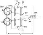
图3示出了包括用于用户单只眼睛的显示组件和显示面板的一部分的头戴式显示设备的一部分的示意性俯视图。在示例图3中,针对用户的每只眼睛,头戴式显示设备102包括刚体305(例如,对应于外壳110的后表面112的一部分)、包括光学块320的显示组件360和显示面板118的一部分。为了说明的目的,图3示出了与单只眼睛350相关联的显示组件360的横截面。因此,可在外壳110中为用户的另一只眼睛提供单独的光学块320和/或显示面板118和/或眼睛跟踪单元215。3 shows a schematic top view of a portion of a head mounted display device including a display assembly for a single eye of a user and a portion of a display panel. In example FIG. 3 , for each eye of the user, head mounteddisplay device 102 includes rigid body 305 (eg, corresponding to a portion ofrear surface 112 of housing 110 ),display assembly 360 includingoptical block 320 anddisplay panel 118 part. For illustrative purposes, FIG. 3 shows a cross-section of thedisplay assembly 360 associated with asingle eye 350 . Accordingly, a separateoptical block 320 and/ordisplay panel 118 and/oreye tracking unit 215 may be provided inhousing 110 for the user's other eye.

在操作中,图3的示例显示组件中的显示面板118的显示像素朝向光学块320发射显示光。光学块320可以包括一个或更多个光学元件,该光学元件包括透镜,诸如图1和图2的透镜104,光学元件被布置成、大小被设计成、被成形为和被定位成组合显示光、放大显示光和/或针对一个或更多个附加光学误差(例如,失真、散光等)校正显示光。光学块320可以包括一个或更多个光圈、菲涅耳透镜、凸透镜、凹透镜、滤光器等,并且可以包括不同光学元件的组合。光学块320的一个或更多个光学元件可以具有一个或更多个涂层,诸如抗反射涂层。光学块320对来自显示面板118的图像光的放大可以允许显示面板118比更大的显示器物理上更小、重量更轻并且消耗更少的功率。另外,显示光的放大可以增加显示内容的视场。例如,所显示内容的视场使得所显示内容使用用户的几乎全部视场(例如,150度对角线)以及在一些情况下用户的全部视场来呈现。光学块320将显示光引导到出射光瞳(exitpupil)340,以呈现给用户的眼睛350。出射光瞳340定位在用户眼睛350的瞳孔354的定位处或附近。尽管图3的示例示出了显示面板和将显示光从显示面板的显示像素引导到出射光瞳340的光学块,但应当理解,可以为头戴式显示设备102提供其他显示组件布置,诸如包括将显示光引导到出射光瞳340(例如,通过使用波导衬底上的一个或更多个光栅将来自投影仪的显示光重定向到出射光瞳)的波导显示器的显示组件。In operation, display pixels ofdisplay panel 118 in the example display assembly of FIG. 3 emit display light towardoptical block 320 .Optical block 320 may include one or more optical elements, including lenses, such aslens 104 of FIGS. 1 and 2, arranged, sized, shaped, and positioned to combine display light , magnify the display light, and/or correct the display light for one or more additional optical errors (eg, distortion, astigmatism, etc.).Optical block 320 may include one or more apertures, Fresnel lenses, convex lenses, concave lenses, filters, etc., and may include combinations of different optical elements. One or more optical elements ofoptical block 320 may have one or more coatings, such as anti-reflection coatings. The magnification of image light fromdisplay panel 118 byoptical block 320 may allowdisplay panel 118 to be physically smaller, lighter in weight, and consume less power than larger displays. In addition, magnification of the display light can increase the field of view of the displayed content. For example, the field of view of the displayed content is such that the displayed content is presented using substantially the entire field of view of the user (eg, 150 degree diagonal), and in some cases the entire field of view of the user.Optical block 320 directs the display light to anexit pupil 340 for presentation to the user'seye 350 . Theexit pupil 340 is positioned at or near the position of thepupil 354 of the user'seye 350 . Although the example of FIG. 3 shows a display panel and optical blocks that direct display light from the display pixels of the display panel to theexit pupil 340, it should be understood that other display component arrangements may be provided for the head mounteddisplay device 102, such as including A display component of a waveguide display that directs display light to an exit pupil 340 (eg, by redirecting display light from a projector to the exit pupil using one or more gratings on the waveguide substrate).

如图3所示,头戴式显示设备102还可以包括一个或更多个眼睛跟踪单元215。眼睛跟踪单元215可以包括一个或更多个相机和/或一个或更多个光源(例如,红外光源),该一个或更多个相机和/或一个或更多个光源被配置用于获得与眼睛350的运动相对应的眼睛跟踪数据。在一个示例中,红外光368在头戴式显示设备102内发射并从用户的每只眼睛350反射。反射的光由相机接收或检测并被分析以提取眼睛旋转信息以从由每只眼睛反射的红外光的变化识别眼睛运动(例如,通过(诸如通过确定眼睛运动的方向和速度)识别注视定位的变化来识别)。As shown in FIG. 3 , the head mounteddisplay device 102 may also include one or moreeye tracking units 215 .Eye tracking unit 215 may include one or more cameras and/or one or more light sources (eg, infrared light sources) configured to Eye tracking data corresponding to the movements of theeyes 350 . In one example,infrared light 368 is emitted within head mounteddisplay device 102 and reflected from eacheye 350 of the user. The reflected light is received or detected by the camera and analyzed to extract eye rotation information to identify eye movement from changes in the infrared light reflected by each eye (eg, by identifying gaze localization (such as by determining the direction and speed of eye movement) change to identify).

如图3所示,用户的眼睛350包括角膜352、瞳孔354、晶状体356、虹膜358、巩膜361和中央凹362。中央凹362被示出为视网膜上的小凹陷。中央凹362对应于用户视网膜的具有最高视觉敏锐度的区域。如图3所示,眼睛350的角度取向对应于朝向显示面板118上的注视定位317的用户注视的方向。本文将注视方向定义为中央凹轴364的方向(包括由光学块320进行的任何修改或重定向),中央凹轴364是眼睛的中央凹与眼睛瞳孔354的中心之间的轴。通常,当用户的眼睛固定在一点上时,用户眼睛的中央凹轴与该点相交。眼睛还包括瞳孔轴366,瞳孔轴是穿过瞳孔354的中心的轴,其垂直于角膜表面352。在一些实施例中,眼睛跟踪单元215检测瞳孔轴的取向,并基于检测到的瞳孔轴来估计中央凹轴364。可替代地,眼睛跟踪单元215通过直接检测中央凹362的定位和/或眼睛视网膜的其他特征的定位来估计中央凹轴。As shown in FIG. 3 , the user'seye 350 includes acornea 352 , apupil 354 , alens 356 , aniris 358 , asclera 361 and afovea 362 . Thefovea 362 is shown as a small depression on the retina. Thefovea 362 corresponds to the area of the user's retina with the highest visual acuity. As shown in FIG. 3 , the angular orientation of theeye 350 corresponds to the direction of the user's gaze toward thegaze location 317 on thedisplay panel 118 . Gaze direction is defined herein as the direction of the foveal axis 364 (including any modification or redirection by optical block 320 ), which is the axis between the fovea of the eye and the center of thepupil 354 of the eye. Typically, when the user's eyes are fixed at a point, the foveal axis of the user's eye intersects that point. The eye also includes a pupillary axis 366 , which is an axis passing through the center of thepupil 354 that is perpendicular to thecorneal surface 352 . In some embodiments, theeye tracking unit 215 detects the orientation of the pupil axis and estimates thefoveal axis 364 based on the detected pupil axis. Alternatively, theeye tracking unit 215 estimates the foveal axis by directly detecting the location of thefovea 362 and/or the location of other features of the retina of the eye.

如下文进一步详细描述的,显示面板118上显示的图像帧可以取决于如头戴式显示设备102所跟踪的用户头部的位置和/或移动。例如,当用户移动其头部以环视虚拟现实场景、增强现实场景、混合现实场景或人工现实场景时,场景中对应于显示面板在该场景中的位置的部分由显示面板显示。As described in further detail below, the image frames displayed ondisplay panel 118 may depend on the position and/or movement of the user's head as tracked by head mounteddisplay device 102 . For example, when a user moves his head to look around a virtual reality scene, an augmented reality scene, a mixed reality scene or an artificial reality scene, a portion of the scene corresponding to the position of the display panel in the scene is displayed by the display panel.

在一些操作情形中,显示器118被操作以提供每个图像帧的中央凹显示。在中央凹显示中,以高分辨率显示图像帧的围绕注视定位317的部分。如图3所示,显示面板118的围绕用户注视定位的部分319可以被用于显示显示图像的高分辨率部分。显示面板118的部分321(其围绕显示图像帧的高分辨率部分的部分319)可以被用于显示过渡区域,在该过渡区域中,显示的图像帧的分辨率随着离注视定位317的距离的增加而降低。显示面板118的剩余部分323可以被用于显示图像帧的相对低的分辨率部分。In some operating situations, thedisplay 118 is operated to provide a foveal display of each image frame. In a foveal display, the portion of the image frame surrounding thegaze location 317 is displayed in high resolution. As shown in FIG. 3, aportion 319 of thedisplay panel 118 positioned around the user's gaze may be used to display a high-resolution portion of the displayed image. Theportion 321 of the display panel 118 (which surrounds theportion 319 that displays the high-resolution portion of the image frame) may be used to display a transition region in which the resolution of the displayed image frame varies with distance from thegaze location 317 increase and decrease. Theremainder 323 of thedisplay panel 118 may be used to display relatively low resolution portions of the image frame.

当用户的注视定位317由于用户眼睛350的旋转而围绕显示面板移动时,显示面板118的对应于图像的高分辨率部分、过渡部分和周边部分的部分319、321和323相应地变化。As the user'sgaze location 317 moves around the display panel due to the rotation of the user'seyes 350, theportions 319, 321 and 323 of thedisplay panel 118 corresponding to the high resolution, transition and peripheral portions of the image change accordingly.

图4示出了可以使用显示面板118显示的中央凹显示图像帧的示例。如图4所示,中央凹显示图像帧401可以包括高分辨率部分430、周边部分400和在高分辨率部分和周边部分之间延伸的过渡部分440。高分辨率部分430、过渡部分440和周边部分400可以分别由显示面板118的部分319、321和323显示(注意,对应于这些部分319、321和323的像素可以随着用户注视定位的变化而变化)。FIG. 4 shows an example of a fovea display image frame that may be displayed usingdisplay panel 118 . As shown in FIG. 4, a fovealdisplay image frame 401 may include ahigh resolution portion 430, aperipheral portion 400, and atransition portion 440 extending between the high resolution portion and the peripheral portion. High-resolution portion 430,transition portion 440, andperipheral portion 400 may be displayed byportions 319, 321, and 323 ofdisplay panel 118, respectively (note that pixels corresponding to theseportions 319, 321, and 323 may Variety).

图像帧401的周边部分400可以具有低于高分辨率部分430的分辨率的分辨率。例如,周边部分400可以具有与人眼的非中央凹区域的分辨率相对应的分辨率。例如,高分辨率部分430可以以对应于人眼的中央凹区域的分辨率显示。Theperipheral portion 400 of theimage frame 401 may have a resolution lower than that of the high-resolution portion 430 . For example, theperipheral portion 400 may have a resolution corresponding to the resolution of the non-foveal region of the human eye. For example, the high-resolution portion 430 may be displayed at a resolution corresponding to the foveal region of the human eye.

如图所示,过渡部分440具有外边界455和内边界460(为了本描述的清楚起见,它们在图4被标记,但是当显示图像401时对用户不可见)。过渡部分440可以被混合,使得分辨率从外边界455以上面讨论的低分辨率部分400的分辨率平滑地变化到内边界460处的高分辨率部分430的高分辨率。另外,可以将过渡部分450褪色(faded)以与背景部分400混合。As shown,transition portion 440 has anouter boundary 455 and an inner boundary 460 (which are labeled in FIG. 4 for clarity of this description, but are not visible to the user whenimage 401 is displayed). Thetransition portion 440 may be blended such that the resolution smoothly changes from the resolution of thelow resolution portion 400 discussed above at theouter boundary 455 to the high resolution of thehigh resolution portion 430 at theinner boundary 460 . Additionally, the transition portion 450 may be faded to blend with thebackground portion 400 .

在图4的示例中,高分辨率部分430具有以用户的注视定位417为中心、在图像401内居中并具有对称圆角的直线边界。然而,应当理解,随着高分辨率部分430根据用户的注视定位317的移动而移动,高分辨率部分430的定位(以及周围的过渡部分440)可以移动得更接近或远离图像401的边缘(例如,在用户的注视定位接近显示面板118的边缘和/或其视场的边缘的情况下)。In the example of FIG. 4, thehigh resolution portion 430 has a straight line boundary centered on the user'sgaze location 417, centered within theimage 401, and with symmetrically rounded corners. It should be understood, however, that as thehigh resolution portion 430 moves according to the movement of the user'sgaze location 317, the location of the high resolution portion 430 (and surrounding transition portion 440) may move closer to or away from the edge of the image 401 ( For example, where the user's gaze is positioned near the edge of thedisplay panel 118 and/or the edge of its field of view).

还应理解,图4的高分辨率部分430和过渡部分440的大小和形状仅是说明性的。高分辨率部分430和/或过渡部分440的其他形状可以包括圆形、卵(oval)形、椭圆(elliptical)形、细长的直线形状等,并且这些形状可以如图4中的示例那样是对称的,或者可以是沿着显示面板的一个或更多个维度不对称的(例如,高分辨率部分430和/或过渡部分440可以沿着用户眼睛305的运动方向伸长)。高分辨率部分430和过渡部分440可以具有相似的、同心的形状和位置,或者可以具有不同的形状和/或在图像401内不同地居中(例如,过渡部分440可以沿着用户眼睛的运动方向伸长并围绕圆形或伸长的高分辨率区域430)。It should also be understood that the size and shape of thehigh resolution portion 430 andtransition portion 440 of FIG. 4 are merely illustrative. Other shapes for thehigh resolution portion 430 and/ortransition portion 440 may include circular, oval, elliptical, elongated rectilinear shapes, etc., and these shapes may be as exemplified in FIG. 4 Symmetrical, or may be asymmetrical along one or more dimensions of the display panel (eg,high resolution portion 430 and/ortransition portion 440 may be elongated along the direction of motion of user's eye 305).High resolution portion 430 andtransition portion 440 may have similar, concentric shapes and positions, or may have different shapes and/or be centered differently within image 401 (eg,transition portion 440 may be along the direction of movement of the user's eyes) Elongate and surround a circular or elongated high-resolution region 430).

为了显示以当前注视定位317为中心的高分辨率区域430和过渡区域440,使得用户在区域440和400中不感知到降低的分辨率,用户的眼睛被跟踪。然而,在可以向用户显示针对该注视定位的中央凹显示图像帧之前,将注视定位提供给显示控制电路,识别与注视定位相关联的内容,渲染、校正和/或以其他方式处理显示图像,并且操作显示像素以显示中央凹显示图像帧401。这些操作(例如,除了诸如头部跟踪和/或接收和/或处理用户输入的其他操作之外的操作)中的每一个都需要时间,使得难以在实时跟踪用户眼睛时完成所有操作。由于这些原因,并且由于使用户的注视定位落在过渡区域440的一部分或低分辨率部分400上可能特别破坏用户的体验,因此提前知晓用户的注视定位是有帮助的(例如,使得处理可以在用户的眼睛到达每个注视定位之前开始)。In order to display ahigh resolution area 430 and atransition area 440 centered on thecurrent gaze location 317 so that the user does not perceive the reduced resolution inareas 440 and 400, the user's eyes are tracked. However, before the foveal display image frame for that gaze location can be displayed to the user, the gaze location is provided to display control circuitry, the content associated with the gaze location is identified, and the display image is rendered, corrected, and/or otherwise processed, And the display pixels are manipulated to display the foveadisplay image frame 401 . Each of these operations (eg, in addition to other operations such as head tracking and/or receiving and/or processing user input) requires time, making it difficult to complete all operations while tracking the user's eyes in real time. For these reasons, and because having the user's gaze location fall on a portion of thetransition region 440 or the low-resolution portion 400 can be particularly disruptive to the user's experience, it is helpful to know the user's gaze location in advance (eg, so that processing can be beginning before the user's eye reaches each fixation).

根据本主题公开的方面,可以获得针对未来显示帧的预测的注视定位,从而可以为该未来显示帧预先生成(例如,预渲染和/或存储)中央凹显示图像帧401。因为未来(预测的)注视定位可能不是确切确定地已知,所以可以基于例如每个预测注视定位的置信水平、用户眼睛350的运动类型和/或其他信息来自适应地修改高分辨率区域430、过渡区域440和背景部分400的大小和/或形状。According to aspects of the subject disclosure, a predicted gaze localization for a future display frame may be obtained, such that a fovealdisplay image frame 401 may be pre-generated (eg, pre-rendered and/or stored) for the future display frame. Because future (predicted) gaze locations may not be known with certainty,high resolution regions 430, The size and/or shape of thetransition area 440 and thebackground portion 400 .

因此,高分辨率区域430可以以当前注视定位或预测的(例如,未来)注视定位为中心。当基于预测的注视定位定位高分辨率部分430时,高分辨率部分430、过渡部分440和/或背景部分400的大小和/或形状可以基于预测(例如,基于未来用户预期达到预测定位的时间的量、基于与预测相关联的置信水平和/或基于在用户预期达到预测定位的时刻要在图像401中显示的内容)来确定。下文描述了注视定位预测和对中央凹显示的一些部分的大小和/或形状的修改的进一步细节。Thus, the high-resolution region 430 may be centered on a current gaze location or a predicted (eg, future) gaze location. When positioning the high-resolution portion 430 based on a predicted gaze location, the size and/or shape of the high-resolution portion 430,transition portion 440, and/orbackground portion 400 may be based on predictions (eg, based on when the future user is expected to reach the predicted location). amount, based on a confidence level associated with the prediction, and/or based on what is to be displayed inimage 401 at the moment the user expects to reach the predicted location). Further details of gaze localization prediction and modification of the size and/or shape of some portions of the foveal display are described below.

除了结合图3和图4描述的中央凹显示特征之外,显示组件360还可以包括用于提供变焦以减少或防止来自辐辏/调节冲突的不期望效果的部件和/或操作。In addition to the foveal display features described in connection with Figures 3 and 4,display assembly 360 may include components and/or operations for providing zoom to reduce or prevent undesired effects from vergence/accommodation conflicts.

例如,在确定并显示与用户正在观看的人工场景的一部分相对应的图像帧(例如,诸如图4的图像帧401的中央凹显示图像帧或均匀分辨率图像帧)之后,系统100然后可以确定用户正在观看的所确定部分内的定位或对象,并相应地调整该定位或对象的焦点。为了确定用户正在观看的虚拟场景的所确定部分内的定位或对象,每只眼睛的眼睛跟踪单元215可以被用于确定注视定位317和/或辐辏平面(例如,垂直于显示面板118的平面,用户两只眼睛的中央凹轴364在该平面处相交)。For example, after determining and displaying an image frame corresponding to a portion of the artificial scene that the user is viewing (eg, a fovea display image frame such asimage frame 401 of FIG. 4 or a uniform resolution image frame),system 100 may then determine The user is viewing a location or object within the determined portion and adjusts the focus of the location or object accordingly. To determine locations or objects within the determined portion of the virtual scene that the user is viewing, theeye tracking unit 215 of each eye may be used to determine thegaze location 317 and/or the vergence plane (eg, the plane perpendicular to thedisplay panel 118, Thefoveal axis 364 of the user's two eyes intersects at this plane).

眼睛跟踪单元215可以被用于跟踪用户的每只眼睛350的眼睛位置、方向和/或取向。例如,头戴式显示设备102可使用来自眼睛跟踪单元215的眼睛跟踪数据来跟踪每只眼睛350的3D位置、滚动(roll)、俯仰(pitch)和偏航(yaw)的至少一个子集,并使用包括或基于这些量的眼睛跟踪数据来估计每只眼睛的注视定位317、辐辏平面和/或3D注视点。此外,来自过去眼睛位置的信息、描述用户头部位置的信息以及描述呈现给用户的场景的信息也可以用于在各种实施例中估计眼睛的3D注视点。Eye tracking unit 215 may be used to track the eye position, direction and/or orientation of eacheye 350 of the user. For example, the head mounteddisplay device 102 may use the eye tracking data from theeye tracking unit 215 to track at least a subset of the 3D position, roll, pitch and yaw of eacheye 350, Thegaze location 317, vergence plane, and/or 3D gaze point for each eye is estimated using eye tracking data including or based on these quantities. Additionally, information from past eye positions, information describing the position of the user's head, and information describing the scene presented to the user may also be used to estimate the 3D gaze point of the eyes in various embodiments.

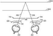
例如,图5示出了显示组件360的展开俯视图,其中可以看到用于双眼350的眼睛跟踪单元215和显示部件。在图5的示例中,眼睛跟踪单元215各自包括相机(例如,包括光源),并且显示组件360包括设置在用户的每只眼睛与显示面板118的针对每只眼睛350的单独部分之间的透镜104(例如,透镜块320中的透镜)。例如,透镜104可以形成包括两个或更多个弯曲光学元件(例如,用于用户左眼和右眼中的每一个的一对薄饼透镜(pancake lens))的薄饼透镜块。For example, FIG. 5 shows an expanded top view ofdisplay assembly 360 in whicheye tracking unit 215 and display components for botheyes 350 can be seen. In the example of FIG. 5 ,eye tracking units 215 each include a camera (eg, including a light source), anddisplay assembly 360 includes a lens disposed between each eye of the user and a separate portion ofdisplay panel 118 for eacheye 350 104 (eg, a lens in lens block 320). For example,lens 104 may form a pancake lens block that includes two or more curved optical elements (eg, a pair of pancake lenses for each of a user's left and right eyes).

在图5的示例中,眼睛跟踪单元215捕获正在观看虚拟对象508的用户眼睛350的图像,该虚拟对象508使用显示面板118在距用户的虚拟距离处显示。头戴式显示设备102可以使用来自眼睛跟踪单元215的眼睛跟踪数据来确定要为每只眼睛350显示的场景内容(例如,基于在显示面板118上为每只眼睛所确定的注视定位317),并确定注视线506的交点(例如,对应于中央凹轴或瞳孔轴,如图3中所述)。辐辏深度(dν)可以基于注视线506的估计交点来确定。辐辏深度可以对应于虚拟对象508的虚拟深度。可以识别与平行于显示面板118并包含注视线506的交点的平面相对应的辐辏平面。In the example of FIG. 5 , theeye tracking unit 215 captures an image of the user'seye 350 viewing avirtual object 508 displayed using thedisplay panel 118 at a virtual distance from the user. The head mounteddisplay device 102 may use the eye tracking data from theeye tracking unit 215 to determine the scene content to be displayed for each eye 350 (eg, based on thegaze location 317 determined for each eye on the display panel 118), And determine the intersection of gaze lines 506 (eg, corresponding to the foveal or pupillary axis, as described in Figure 3). The vergence depth (dν ) may be determined based on the estimated intersection of the gaze lines 506 . The vergence depth may correspond to the virtual depth ofvirtual object 508 . A plane of convergence can be identified that corresponds to a plane parallel to thedisplay panel 118 and containing the intersection of the lines ofgaze 506 .

为了改变头戴式显示设备102的光学系统的焦距(或焦度),从而针对所确定的辐辏深度提供调节,该确定的辐辏深度对应于用户正在观看的虚拟场景的被显示部分的位置或被显示部分中的内容,基于所确定的辐辏深度和/或辐辏平面,可以相对于用户眼睛350和/或相对于显示组件的其他部件移动显示组件360的一个或更多个部件。作为示例,多透镜块中的一个或更多个透镜104可以朝向或远离用户的眼睛移动,或者朝向或远离多透镜块中的另一个透镜移动,透镜104中的一个或更多个可以变形以改变通过该透镜的光路来修改光学系统的焦距,显示面板118可以朝向或远离用户眼睛350和/或朝向或远离透镜104移动,和/或透镜104可以朝向或远离用户眼睛350和/或朝向或远离显示面板118移动。To vary the focal length (or power) of the optical system of the head mounteddisplay device 102, thereby providing an adjustment to the determined vergence depth that corresponds to the position of the displayed portion of the virtual scene that the user is viewing or is The content in the display portion, based on the determined vergence depth and/or vergence plane, may move one or more components ofdisplay assembly 360 relative touser eye 350 and/or relative to other components of display assembly. As an example, one ormore lenses 104 in a multi-lens block may move toward or away from the user's eye, or toward or away from another lens in the multi-lens block, one or more of thelenses 104 may be deformed to Changing the light path through the lens to modify the focal length of the optical system, thedisplay panel 118 can move toward or away from the user'seye 350 and/or toward or away from thelens 104, and/or thelens 104 can move toward or away from the user'seye 350 and/or toward or Move away from thedisplay panel 118 .

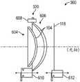
例如,图6示出了显示组件360的一部分的横截面视图,其中透镜块320是具有彼此间隔开的两个弯曲透镜104的薄饼透镜块。在该示例中,透镜块320设置有致动器610(例如,马达、压电部件等),该致动器被布置成修改透镜104中的一个的位置和/或形状,以调整头戴式显示设备102的光学系统的焦距(或焦度),从而移动所得到的图像平面并为所确定的辐辏深度提供调节。在一个示例中,修改透镜104中的一个的位置和/或形状包括改变后光学元件606和前光学元件604之间的距离。在另一示例中,修改透镜104中的一个的位置和/或形状包括将力施加到两个光学元件中较大的一个(例如,后光学元件606)。在另一示例中,可以同时改变两个光学元件604和606的形状,或者改变光学元件的形状中的至少一个或改变两个光学元件之间的距离的组合可以被用来改变透镜块320的焦距。For example, FIG. 6 shows a cross-sectional view of a portion ofdisplay assembly 360 where lens block 320 is a pancake lens block having twocurved lenses 104 spaced apart from each other. In this example, thelens block 320 is provided with an actuator 610 (eg, motor, piezoelectric component, etc.) arranged to modify the position and/or shape of one of thelenses 104 to adjust the head-mounted display The focal length (or power) of the optical system ofdevice 102, thereby moving the resulting image plane and providing adjustment for the determined depth of vergence. In one example, modifying the position and/or shape of one of thelenses 104 includes changing the distance between the rearoptical element 606 and the frontoptical element 604 . In another example, modifying the position and/or shape of one oflenses 104 includes applying a force to the larger of the two optical elements (eg, rear optical element 606). In another example, the shapes of bothoptical elements 604 and 606 may be changed simultaneously, or a combination of changing at least one of the shapes of the optical elements or changing the distance between the two optical elements may be used to change the size of thelens block 320 focal length.

在一个示例中,修改透镜104中的一个的位置和/或形状包括操作音圈马达,该音圈马达能够提供大约3-4mm的线性行程,以相对于前光学元件604移动后光学元件606。还可以提供导轴(guide shaft)608或其他结构限制器以引导后光学元件606的移动并防止倾斜。在一些实施例中,压电马达或某种其他合适的马达可用作该实现中音圈马达的替代方案。In one example, modifying the position and/or shape of one of thelenses 104 includes operating a voice coil motor capable of providing approximately 3-4 mm of linear travel to move the rearoptical element 606 relative to the frontoptical element 604 . Aguide shaft 608 or other structural restraint may also be provided to guide movement of the rearoptical element 606 and prevent tilting. In some embodiments, a piezoelectric motor or some other suitable motor may be used as an alternative to a voice coil motor in this implementation.

在另一示例中,后光学元件606可以安装在固定外壳或螺纹环中,并且可以在外边缘上包括阳螺纹(male thread),而螺纹环的内部包括阴螺纹(female thread)。在另一示例中,透镜104可设置在真空压力外壳内,使得透镜104之间或周围的真空压力可以被用于基于所确定的辐辏平面/深度改变光学系统的焦距。In another example, the rearoptical element 606 may be mounted in a stationary housing or a threaded ring and may include male threads on the outer edge while the interior of the threaded ring includes female threads. In another example, thelenses 104 may be disposed within a vacuum pressure enclosure such that vacuum pressure between or around thelenses 104 may be used to change the focal length of the optical system based on the determined plane/depth of vergence.

除了这些用于变焦致动的示例之外,还应当理解,光学系统的焦点还可以或者可替代地通过调整诸如液体可调透镜、液晶光学器件、多焦光学器件、光场显示器、多焦液晶光学器件、Alvarez透镜和/或Pancharatnam-Berry相位(PBP)透镜(作为示例)的其他部件来修改。In addition to these examples for zoom actuation, it should be understood that the focal point of the optical system may also or alternatively be adjusted by means of adjustments such as liquid tunable lenses, liquid crystal optics, multifocal optics, light field displays, multifocal liquid crystals Other components of optics, Alvarez lenses and/or Pancharatnam-Berry phase (PBP) lenses (as examples) are modified.

如图6所示,致动器612还可以或可替代地耦合到显示面板118,以基于所确定的辐辏平面/距离来调整包括显示面板118和透镜块320的光学系统的图像平面。As shown in FIG. 6 ,actuator 612 may also or alternatively be coupled todisplay panel 118 to adjust the image plane of the optical system includingdisplay panel 118 and lens block 320 based on the determined vergence plane/distance.

在本文所描述的用于致动显示系统的部件以调整焦距和/或所得到的图像平面的各种实现中的任何一个中,为减少调节/辐辏冲突,用于致动光学元件的时间可能导致不希望的效果,诸如渲染中的延迟、帧丢失,和/或可能太晚而无法赶上用户的眼睛运动。In any of the various implementations described herein for actuating components of a display system to adjust focus and/or resulting image plane, to reduce adjustment/vergence conflicts, the time for actuating optical elements may be Causes undesired effects, such as delays in rendering, dropped frames, and/or may be too late to catch up with the user's eye movement.

根据本主题公开的方面,可以获得用于未来显示帧的预测的辐辏平面和/或辐辏深度,从而可以提前开始针对该未来显示帧的光学元件调整。由于未来(预测的)辐辏平面/深度可能不是确切确定地已知,因此与每个预测的辐辏平面相关联的舒适区可以基于例如针对每个预测的辐辏平面的置信水平和/或其他信息(诸如在未来显示帧时的场景内容信息、用户校准信息和/或用户建模数据)来自适应地修改。下文描述了辐辏平面预测以及对舒适区的修改和对变焦部件的致动的进一步细节。According to aspects of the subject disclosure, predicted vergence planes and/or vergence depths for future display frames can be obtained so that optical element adjustments for that future display frame can be initiated in advance. Since future (predicted) vergence planes/depths may not be known with exact certainty, the comfort zone associated with each predicted vergence plane may be based on, for example, a confidence level and/or other information for each predicted vergence plane ( Such as scene content information, user calibration information, and/or user modeling data when displaying frames in the future) to be adaptively modified. The vergence plane prediction and further details of the modification of the comfort zone and actuation of the zoom components are described below.

图7示出了系统100的各种部件的示意图,包括用于预测注视定位和/或辐辏平面的部件,和/或用于预测性中央凹显示和/或预测性变焦操作的部件。如图7所示,系统100可包括具有显示面板118和透镜块320的头戴式显示设备102。在该示例中,系统100也包括成像设备760和输入接口770,它们各自耦合到控制台750。7 shows a schematic diagram of various components ofsystem 100, including components for predictive gaze localization and/or vergence planes, and/or components for predictive foveal display and/or predictive zoom manipulation. As shown in FIG. 7 ,system 100 may include head mounteddisplay device 102 havingdisplay panel 118 andlens block 320 . In this example,system 100 also includesimaging device 760 andinput interface 770 , each coupled toconsole 750 .

尽管图7示出了单个头戴式显示设备102、单个成像设备760和单个输入接口770,但应当理解,系统中可以包括任意数量的这些部件。例如,系统100可以包括多个头戴式显示设备102,每个显示设备有相关联的输入接口770,并且由一个或更多个成像设备760监测,其中每个头戴式显示设备102、输入接口770和成像设备760都与控制台750通信。在替代配置中,在系统100中也可以包括不同的和/或附加的部件。Although FIG. 7 shows a single head mounteddisplay device 102, asingle imaging device 760, and asingle input interface 770, it should be understood that any number of these components may be included in the system. For example,system 100 may include a plurality of head mounteddisplay devices 102, each display device having an associatedinput interface 770 and monitored by one ormore imaging devices 760, wherein each head mounteddisplay device 102, an input Both theinterface 770 and theimaging device 760 are in communication with theconsole 750 . In alternate configurations, different and/or additional components may also be included insystem 100 .

头戴式显示设备102操作显示器118和/或诸如音频部件的其他部件以向用户呈现内容。在该示例中,头戴式显示设备102包括变焦致动块706、聚焦预测模块708、眼睛跟踪模块710、辐辏处理模块712、一个或更多个定位器714、内部测量单元(IMU)716、头部跟踪传感器718、场景渲染模块720以及眼睛预测模块722。Head mounteddisplay device 102 operatesdisplay 118 and/or other components such as audio components to present content to a user. In this example, the head mounteddisplay device 102 includes azoom actuation block 706, afocus prediction module 708, aneye tracking module 710, avergence processing module 712, one or more localizers 714, an internal measurement unit (IMU) 716,Head tracking sensor 718 ,scene rendering module 720 andeye prediction module 722 .

变焦致动块706包括一个或更多个变焦元件(例如,图6的致动器610或612中的一个或更多个、一个或更多个液体可调透镜、光场显示器的一个或更多个微透镜等),该变焦元件调整光学块320的一个或更多个部件和/或显示面板118以改变头戴式显示设备102的焦距(或光焦度),以在辐辏和调节改变时使用户的眼睛保持在舒适区。在其中变焦元件的调整是部件的机械移动的一个示例中,变焦致动块706基于针对用户的预测的辐辏平面和/或当前辐辏平面物理地改变光学块320的两个光学元件之间的距离。在机械聚焦变化的相同示例中,可替代地,或者除了改变光学元件之间的距离之外,变焦致动块706可以通过向图6中描述的后光学元件606或前光学元件604中的一个施加力来改变光学块320的焦距。在机械和/或其他变焦实现的各种示例中,变焦致动块706可以包括致动器、马达、真空压力控制器、可控偏振器、用于调节液体可调透镜和/或其他液晶光学器件的电子和/或机械部件、光场显示部件等,其改变光学块320的至少一个光学元件的形状、位置、取向和/或相位、偏振和/或其他响应度。变焦致动块706可以基于当前辐辏平面或基于针对用户的预测的辐辏平面来调整光学块320和/或显示面板118的布置。Thezoom actuation block 706 includes one or more zoom elements (eg, one or more of theactuators 610 or 612 of FIG. 6 , one or more liquid tunable lenses, one or more of the light field display microlenses, etc.), the zoom element adjusts one or more components of theoptical block 320 and/or thedisplay panel 118 to change the focal length (or optical power) of the head mounteddisplay device 102 to change in vergence and adjustment Keep the user's eyes in the comfort zone. In one example where the adjustment of the zoom element is a mechanical movement of a component, thezoom actuation block 706 physically changes the distance between the two optical elements of the optics block 320 based on the predicted vergence plane and/or the current vergence plane for the user . In the same example of a mechanical focus change, alternatively, or in addition to changing the distance between the optical elements, thezoom actuation block 706 can be adjusted to one of the rearoptical element 606 or the frontoptical element 604 described in FIG. A force is applied to change the focal length of theoptical block 320 . In various examples of mechanical and/or other zoom implementations,zoom actuation block 706 may include actuators, motors, vacuum pressure controllers, controllable polarizers, adjustable lenses for adjusting liquids, and/or other liquid crystal optics Electronic and/or mechanical components of a device, light field display components, etc. that alter the shape, position, orientation and/or phase, polarization and/or other responsivity of at least one optical element ofoptical block 320 . Thezoom actuation block 706 may adjust the arrangement of theoptical block 320 and/or thedisplay panel 118 based on the current vergence plane or based on a predicted vergence plane for the user.

例如,变焦致动块706可以设置和/或改变光学块320的状态和/或显示面板118的状态,以实现期望的焦距和/或对象距离,这减轻了针对用户的特定的当前或预测的辐辏平面的调节/辐辏冲突。For example, thezoom actuation block 706 may set and/or change the state of theoptical block 320 and/or the state of thedisplay panel 118 to achieve the desired focus and/or object distance, which alleviates the user-specific current or predicted Conditioning/vergence conflict at the vergence plane.

聚焦预测模块708是包括逻辑的编码器,该逻辑跟踪光学块320的状态,以预测光学块320的一个或更多个未来状态。例如,聚焦预测模块708累积对应于光学块320的先前状态的历史信息,并基于先前状态预测光学块320的未来状态。由于基于光学块320的状态来调整设备102对场景的渲染,因此预测的状态允许场景渲染模块720(下面进一步描述)确定要应用于特定帧的场景的调整。因此,聚焦预测模块708将描述用于帧的光学块320的预测状态的信息传送到场景渲染模块720。下面进一步描述由场景渲染模块720执行的针对光学块320的不同状态的调整。聚焦预测模块708可以操作来预测光学块320的状态,以甚至用于基于当前辐辏平面的变焦操作。Focus prediction module 708 is an encoder that includes logic that tracks the state ofoptical block 320 to predict one or more future states ofoptical block 320 . For example, focusprediction module 708 accumulates historical information corresponding to previous states ofoptical block 320 and predicts future states ofoptical block 320 based on the previous state. Since the rendering of the scene bydevice 102 is adjusted based on the state of optics block 320, the predicted state allows scene rendering module 720 (described further below) to determine adjustments to apply to the scene of a particular frame. Accordingly, thefocus prediction module 708 transmits information to thescene rendering module 720 describing the predicted state of theoptical block 320 for the frame. The adjustments performed by thescene rendering module 720 for different states of theoptical block 320 are described further below. Thefocus prediction module 708 is operable to predict the state of theoptical block 320 for even zoom operations based on the current vergence plane.

眼睛跟踪模块710可以从眼睛跟踪单元215接收眼睛跟踪数据,并基于眼睛跟踪数据跟踪用户眼睛350的眼睛位置和眼睛运动。头戴式显示设备102内部的眼睛跟踪单元215的相机或其他光学传感器捕获用户眼睛的图像信息,并且眼睛跟踪模块710使用捕获的图像信息来确定瞳间(interpupillary)距离、眼间距离、每只眼睛350相对于显示面板118和/或透镜104中的一个或更多个的三维(3D)位置(例如,用于失真调节目的),包括扭转和旋转(例如,滚动、俯仰和偏航)的幅度。Theeye tracking module 710 may receive eye tracking data from theeye tracking unit 215 and track the eye position and eye movement of the user'seyes 350 based on the eye tracking data. The camera or other optical sensor of theeye tracking unit 215 inside the head mounteddisplay device 102 captures image information of the user's eyes, and theeye tracking module 710 uses the captured image information to determine the interpupillary distance, the The three-dimensional (3D) position ofeye 350 relative to displaypanel 118 and/or one or more of lens 104 (eg, for distortion adjustment purposes), including twist and rotation (eg, roll, pitch, and yaw) magnitude.

眼睛跟踪模块710可以跟踪每只眼睛350的多达六个自由度(例如,3D位置、滚动、俯仰和偏航),并且可以从用户的两只眼睛组合所跟踪的量的至少一个子集以估计注视定位和/或辐辏平面。在一些示例中,可以确定虚拟场景中用户注视的3D定位或位置。例如,眼睛跟踪模块710整合来自过去的眼睛跟踪测量的信息、识别用户头部位置的测量值、以及描述由显示面板118呈现的场景的3D内容信息。Eye tracking module 710 can track up to six degrees of freedom (eg, 3D position, roll, pitch, and yaw) of eacheye 350, and can combine at least a subset of the amounts tracked from both eyes of the user to Estimate gaze localization and/or vergence plane. In some examples, the 3D position or position of the user's gaze in the virtual scene may be determined. For example,eye tracking module 710 integrates information from past eye tracking measurements, measurements identifying the position of the user's head, and 3D content information describing the scene presented bydisplay panel 118 .

眼睛跟踪模块710可以输出眼睛跟踪数据,诸如每只眼睛的过去注视方向的集合、用户眼睛的过去辐辏平面的集合、每只眼睛的当前注视方向、用户眼睛的当前辐辏平面、和/或用户每只眼睛的运动的当前方向、速度和/或加速度。可以将从眼睛跟踪模块710输出的眼睛跟踪数据提供给头戴式显示设备102的辐辏处理模块、场景渲染模块720、聚焦预测模块708和/或眼睛预测模块722。也可以将从眼睛跟踪模块输出的眼睛跟踪数据在头戴式显示设备102的外部提供到例如控制台750的人工现实引擎756。Eye tracking module 710 can output eye tracking data, such as a set of past gaze directions for each eye, a set of past vergence planes for the user's eyes, the current gaze direction for each eye, the current vergence plane for the user's eyes, and/or the user's eye's current vergence plane. The current direction, velocity, and/or acceleration of eye-only movement. The eye tracking data output from theeye tracking module 710 may be provided to the vergence processing module, thescene rendering module 720 , thefocus prediction module 708 and/or theeye prediction module 722 of the head mounteddisplay device 102 . The eye tracking data output from the eye tracking module may also be provided external to the head mounteddisplay device 102 to anartificial reality engine 756 such as theconsole 750 .

眼睛预测模块722可以基于从眼睛跟踪模块接收的眼睛跟踪数据(例如,当前注视定位、当前辐辏平面、以及当前和过去的注视方向、每只眼睛运动的速度和/或加速度)和/或其他信息(例如,场景内容信息和/或用户校准信息)来生成一个或更多个预测的注视定位和/或一个或更多个预测的辐辏平面。预测的注视定位和/或预测的辐辏平面可以基于在眼睛运动期间用户眼睛的速度和/或加速度的前两个、前三个或前三个以上的测量值来确定。眼睛预测模块722可以为要由显示面板118显示的下一个图像帧和/或为一个或更多个后续图像帧生成预测的注视定位和/或预测的辐辏平面。作为示例,眼睛预测模块722可以为注视定位和/或辐辏平面生成接下来的一帧预测、两帧预测、三帧预测、五帧预测、十帧预测等。作为另一个示例,眼睛预测模块722可以为多个即将到来的时间生成多个预测,诸如10毫秒(ms)预测、20ms预测、30ms预测、50毫秒预测和100ms预测。例如,对于辐辏平面预测,变焦致动块706可以具有已知的最大调整时间(例如,以ms为单位)。眼睛预测模块722可以生成未来时间的预测的辐辏平面,这些时间基于变焦致动块706中的该已知延迟(例如,该已知延迟的一倍或更多倍)。应当理解,这些预测时间可以独立于显示帧时间。Theeye prediction module 722 may be based on eye tracking data received from the eye tracking module (eg, current gaze location, current vergence plane, and current and past gaze direction, speed and/or acceleration of each eye movement) and/or other information (eg, scene content information and/or user calibration information) to generate one or more predicted gaze locations and/or one or more predicted vergence planes. The predicted gaze location and/or the predicted vergence plane may be determined based on the first two, three or more measurements of the speed and/or acceleration of the user's eyes during eye movement.Eye prediction module 722 may generate a predicted gaze location and/or a predicted vergence plane for the next image frame to be displayed bydisplay panel 118 and/or for one or more subsequent image frames. As an example, theeye prediction module 722 may generate next-frame predictions, two-frame predictions, three-frame predictions, five-frame predictions, ten-frame predictions, etc., for gaze localization and/or vergence planes. As another example, theeye prediction module 722 may generate multiple predictions for multiple upcoming times, such as 10 millisecond (ms) predictions, 20 ms predictions, 30 ms predictions, 50 ms predictions, and 100 ms predictions. For example, for vergence plane prediction, thezoom actuation block 706 may have a known maximum adjustment time (eg, in ms).Eye prediction module 722 may generate predicted vergence planes for future times based on the known delay in zoom actuation block 706 (eg, one or more times the known delay). It should be understood that these prediction times may be independent of display frame times.

眼睛预测模块722可以生成针对每个预测的注视定位和/或辐辏平面的置信水平。例如,在用户眼睛的特定运动期间,当在运动期间从眼睛跟踪模块710提供更多眼睛跟踪数据时,在该运动结束时针对预测的注视定位和/或辐辏平面的置信水平可以提高。下文(例如,结合图8)将描述眼睛预测模块722的另外的特征。Eye prediction module 722 may generate a confidence level for each predicted gaze location and/or vergence plane. For example, during a particular movement of the user's eyes, as more eye tracking data is provided from theeye tracking module 710 during the movement, the confidence level for the predicted gaze location and/or vergence plane at the end of the movement may increase. Additional features of theeye prediction module 722 will be described below (eg, in conjunction with FIG. 8).

辐辏处理模块712可以对从眼睛跟踪模块710接收的辐辏深度或辐辏平面进行操作,以确定对光学块320和/或显示器110的修改,以实现对应的图像平面深度,从而保持用户的舒适区。在一些实现中,当前辐辏深度也可以或者可替代地由辐辏处理模块712(例如,基于从眼睛跟踪模块710提供的针对每只眼睛的注视方向信息)确定。Thevergence processing module 712 may operate on the vergence depths or vergence planes received from theeye tracking module 710 to determine modifications to the optics block 320 and/or thedisplay 110 to achieve the corresponding image plane depths to maintain the user's comfort zone. In some implementations, the current vergence depth may also or alternatively be determined by vergence processing module 712 (eg, based on gaze direction information provided fromeye tracking module 710 for each eye).

定位器714是相对于彼此并且相对于头戴式显示设备102上的特定参考点位于头戴式显示设备102上特定位置的部件。定位器714可以被实现为发光二极管(LED)、角立方体反射器(corner cube reflector)、反射标记(reflective marker)、与头戴式显示设备102的操作环境形成对比的另一种类型的光源、或它们的某种组合。有源定位器714(例如,LED或其他类型的发光设备)可以发射在可见光波段(例如,380nm至750nm之间)中、在红外(IR)波段(例如,750nm至1mm之间)中、在紫外波段(例如,10nm至380nm之间)中、电磁波谱的某个其他部分、或它们的某种组合中的光。Thelocators 714 are components that are located at particular locations on the head mounteddisplay device 102 relative to each other and relative to a particular reference point on the head mounteddisplay device 102 .Positioner 714 may be implemented as a light emitting diode (LED), corner cube reflector, reflective marker, another type of light source that contrasts with the operating environment of head mounteddisplay device 102, or some combination of them. Active localizers 714 (eg, LEDs or other types of light emitting devices) may emit in the visible light band (eg, between 380 nm and 750 nm), in the infrared (IR) band (eg, between 750 nm and 1 mm), in the Light in the ultraviolet wavelength band (eg, between 10 nm and 380 nm), in some other part of the electromagnetic spectrum, or some combination thereof.

定位器714可以位于头戴式显示设备102的外表面之下,该外表面对于由定位器714发射或反射的光的波长是透光的,或者足够薄而基本上不使由定位器714发射或反射的光的波长衰减。此外,头戴式显示设备102的外表面或其他部分在光波长的可见光波段中可以是不透光(opaque)的。因此,定位器714当在头戴式显示设备102的外表面下时可以发射在IR波段中的光,该外表面在IR波段中是透光的但在可见光波段中是不透光的。Thepositioner 714 may be located below an outer surface of the head mounteddisplay device 102 that is transparent to the wavelengths of light emitted or reflected by thepositioner 714 , or thin enough to be substantially not emitted by thepositioner 714 or wavelength attenuation of reflected light. Additionally, the outer surface or other portion of the head mounteddisplay device 102 may be opaque in the visible wavelength band of light. Thus, thepositioner 714 may emit light in the IR band when under the outer surface of the head mounteddisplay device 102, which is transparent in the IR band but opaque in the visible band.

惯性测量单元(IMU)716是基于从一个或更多个头部跟踪传感器718接收的测量信号来生成快速校准数据的电子设备,头部跟踪传感器718响应于头戴式显示设备102的运动生成一个或更多个测量信号。头部跟踪传感器718的示例包括加速度计、陀螺仪、磁力计、适于检测运动、校正与IMU 716相关联的误差的其他传感器或者其某种组合。头部跟踪传感器718可以位于IMU 716的外部、IMU 716的内部或者其某种组合。Inertial measurement unit (IMU) 716 is an electronic device that generates rapid calibration data based on measurement signals received from one or morehead tracking sensors 718 that generate a or more measurement signals. Examples ofhead tracking sensors 718 include accelerometers, gyroscopes, magnetometers, other sensors suitable for detecting motion, correcting errors associated withIMU 716, or some combination thereof. Thehead tracking sensor 718 may be located external to theIMU 716, internal to theIMU 716, or some combination thereof.

基于来自头部跟踪传感器718的测量信号,IMU 716生成快速校准数据,该快速校准数据指示头戴式显示设备102相对于头戴式显示设备102的初始位置的估计位置。例如,头部跟踪传感器718包括测量平移运动(向前/向后、向上/向下、向左/向右)的多个加速度计和测量旋转运动(例如,俯仰、偏航、和横滚)的多个陀螺仪。例如,IMU 716可以对测量信号进行快速采样,并根据采样的数据计算头戴式显示设备102的估计位置。例如,IMU 716在时间上对从加速度计接收的测量信号进行积分以估计速度向量,并在时间上对速度向量进行积分以确定头戴式显示设备102上参考点的估计位置。参考点是可以用来描述头戴式显示设备102的位置的点。虽然参考点通常可以被定义为空间中的点,但是在各种实施例中参考点被定义为在头戴式显示设备102内的点(例如,IMU 716的中心)。可替代地,IMU 716向控制台750提供所采样的测量信号,控制台750确定快速校准数据。Based on the measurement signals from thehead tracking sensor 718 , theIMU 716 generates fast calibration data indicating the estimated position of the head mounteddisplay device 102 relative to the initial position of the head mounteddisplay device 102 . For example,head tracking sensor 718 includes multiple accelerometers that measure translational motion (forward/backward, up/down, left/right) and rotational motion (eg, pitch, yaw, and roll) of multiple gyroscopes. For example, theIMU 716 may rapidly sample the measurement signal and calculate an estimated position of the head mounteddisplay device 102 from the sampled data. For example, theIMU 716 integrates the measurement signals received from the accelerometers over time to estimate the velocity vector, and integrates the velocity vector over time to determine the estimated location of the reference point on the head mounteddisplay device 102 . A reference point is a point that can be used to describe the position of the head mounteddisplay device 102 . Although a reference point may generally be defined as a point in space, in various embodiments a reference point is defined as a point within the head mounted display device 102 (eg, the center of the IMU 716). Alternatively,IMU 716 provides the sampled measurement signals to console 750, which determines quick calibration data.

IMU 716可以附加地从控制台750接收一个或更多个校准参数。如下面进一步讨论的,一个或更多个校准参数用于保持对头戴式显示设备102的跟踪。基于接收到的校准参数,IMU 716可以调整一个或更多个IMU参数(例如,采样率)。在一些实施例中,某些校准参数使IMU 716更新参考点的初始位置以对应于参考点的下一个校准位置。将参考点的初始位置更新为参考点的下一个校准位置有助于减少与确定估计位置相关联的累积误差。累积误差(也称为漂移误差(drift error))导致参考点的估计位置随着时间的推移“漂移”远离参考点的实际位置。IMU 716 may additionally receive one or more calibration parameters fromconsole 750 . As discussed further below, one or more calibration parameters are used to keep track of the head mounteddisplay device 102 . Based on the received calibration parameters,IMU 716 may adjust one or more IMU parameters (eg, sampling rate). In some embodiments, certain calibration parameters cause theIMU 716 to update the initial position of the reference point to correspond to the next calibration position of the reference point. Updating the initial position of the reference point to the next calibrated position of the reference point helps reduce the accumulated error associated with determining the estimated position. Accumulated error (also known as drift error) causes the estimated position of the reference point to "drift" away from the actual position of the reference point over time.

场景渲染模块720从人工现实引擎756接收用于人工场景的内容,并提供该内容以在显示面板118上显示。另外,场景渲染模块720可以基于来自聚焦预测模块708、辐辏处理模块712、IMU 716、头部跟踪传感器718和眼睛预测模块722的信息来调整内容。例如,在从引擎756接收到内容时,场景渲染模块720基于从聚焦预测模块708接收到的光学块320的预测状态来调整内容。例如,场景渲染模块720可将失真校正应用于要显示的显示内容(例如,通过在显示之前基于光学块320的预测状态来扭曲所渲染的图像帧),以抵消可能由光学块320的光学元件引起的所显示图像帧的任何失真。预测的三维注视定位(例如,其基于预测的注视定位和预测的辐辏平面)可以被用于在一些情形中预测该失真校正(例如,通过将预测的三维注视定位提供给聚焦预测模块708)。另外,如下面进一步描述的,场景渲染模块720基于跟踪模块754、头部跟踪传感器718或IMU 716中的一个或更多个来确定待显示在电子显示器118上的内容的一部分。Thescene rendering module 720 receives content for the artificial scene from theartificial reality engine 756 and provides the content for display on thedisplay panel 118 . Additionally,scene rendering module 720 may adjust content based on information fromfocus prediction module 708 ,vergence processing module 712 ,IMU 716 ,head tracking sensor 718 , andeye prediction module 722 . For example, upon receiving content fromengine 756 ,scene rendering module 720 adjusts the content based on the predicted state ofoptical block 320 received fromfocus prediction module 708 . For example, thescene rendering module 720 may apply distortion correction to the display content to be displayed (eg, by distorting the rendered image frame based on the predicted state of theoptical block 320 prior to display) to counteract the optical elements that may be caused by theoptical block 320 Any distortion of the displayed image frame caused. The predicted 3D fixation location (eg, which is based on the predicted fixation location and the predicted vergence plane) may be used to predict the distortion correction in some cases (eg, by providing the predicted 3D fixation location to focus prediction module 708). Additionally, as described further below, thescene rendering module 720 determines a portion of the content to be displayed on theelectronic display 118 based on one or more of the tracking module 754 , thehead tracking sensor 718 , or theIMU 716 .

如本文所述,场景渲染模块720和/或头戴式显示设备102和/或控制台750内的其他处理电路可将图像帧(或图像帧系列)划分为高分辨率部分430、过渡部分440和周边部分400,以渲染中央凹显示图像帧以用于由显示面板118显示。As described herein,scene rendering module 720 and/or other processing circuitry within head mounteddisplay device 102 and/orconsole 750 may divide an image frame (or series of image frames) intohigh resolution portion 430,transition portion 440 andperipheral portion 400 to render a fovea display image frame for display bydisplay panel 118 .

场景渲染模块720基于来自眼睛跟踪模块710的当前注视定位和/或来自眼睛预测模块722的一个或更多个预测的注视定位来确定要渲染的高分辨率区域430、过渡区域440和周边区域400中的每一个的定位、大小和/或形状。场景渲染模块720然后可以例如以目标分辨率(例如,对应于人眼的中央凹区域的分辨率)渲染高分辨率区域430,并且以低于高分辨率部分430的分辨率的分辨率渲染周边部分400。在一些操作情形中,高分辨率区域430可以被上采样(诸如经由超分辨率技术上采样)(如果需要的话)以实现目标分辨率。在一些操作情形中,场景渲染模块720可以基于预测的注视定位和针对该预测的注视定位的置信水平来调整周边部分400的内容。例如,场景渲染模块720可以根据针对预测的注视定位的置信水平对周边部分400应用填充(fill)。Thescene rendering module 720 determines thehigh resolution area 430 , thetransition area 440 and the surroundingarea 400 to render based on the current gaze location from theeye tracking module 710 and/or one or more predicted gaze locations from theeye prediction module 722 The positioning, size and/or shape of each of the . Thescene rendering module 720 may then render the high-resolution region 430 at a target resolution (eg, a resolution corresponding to the foveal region of the human eye), and render the perimeter at a lower resolution than the resolution of the high-resolution portion 430, forexample Section 400. In some operational situations, the high-resolution region 430 may be upsampled (such as via super-resolution techniques), if desired, to achieve the target resolution. In some operational situations,scene rendering module 720 may adjust the content ofperipheral portion 400 based on the predicted gaze location and a confidence level for the predicted gaze location. For example, thescene rendering module 720 may apply a fill to theperipheral portion 400 according to the confidence level for the predicted gaze location.

场景渲染模块720还可以应用混合函数来调整要渲染的过渡部分440的分辨率,使得在渲染时,分辨率从图像的高分辨率部分430的分辨率平滑地过渡到背景区域400的分辨率。混合函数可以对应于与从人眼的中央凹到非中央凹区域的过渡相关联的敏锐度下降。混合函数可以是例如高斯金字塔分解函数、高斯混合函数、从嵌入(inset)区域的分辨率平滑地过渡到背景区域的分辨率的某个函数或其某种组合。另外,金字塔混合函数可以包括执行高斯金字塔分解(例如,用适当的平滑滤波器平滑内容,然后对平滑内容进行子采样,并继续该处理以达到预定的采样密度水平)。可以使用高斯混合函数将子采样和已平滑的内容混合到原始内容。混合的过渡部分可用于复合内容的过渡区域440。Thescene rendering module 720 may also apply a blending function to adjust the resolution of thetransition portion 440 to be rendered so that upon rendering, the resolution transitions smoothly from the resolution of thehigh resolution portion 430 of the image to the resolution of thebackground region 400 . The blending function may correspond to a decrease in acuity associated with the transition from the foveal to non-foveal region of the human eye. The mixture function may be, for example, a Gaussian pyramid decomposition function, a Gaussian mixture function, some function that smoothly transitions from the resolution of the inset region to the resolution of the background region, or some combination thereof. Additionally, the pyramid mixing function may include performing a Gaussian pyramid decomposition (eg, smoothing the content with an appropriate smoothing filter, then subsampling the smoothed content, and continuing the process to reach a predetermined level of sampling density). Subsampled and smoothed content can be blended to the original content using a Gaussian mixture function. The blended transition portion may be used in thetransition area 440 of the composite content.

场景渲染模块720还可以使用强度褪色函数在周边部分400和/或过渡部分440中褪色(例如,减小显示强度)。在一些操作情况下,场景渲染模块720可以基于预测的辐辏平面来调整高分辨率部分430、过渡部分440和/或周边部分400中的一个或更多个中的一些或全部的分辨率(例如,通过有意模糊高分辨率区域430中的对象,该对象与用户的眼睛进行辐辏(verged)的高分辨率区域中的另一个对象处于不同深度),以增强允许用户对各种对象进行辐辏并聚焦于各种对象的深度线索。这种人工散焦(defocus)模糊可以进一步帮助模拟其中眼睛具有有限景深的真实世界效果。由于所显示的图像帧可能完全在单个焦平面上,即使该图像帧可能包含不同深度的对象,场景渲染模块也可以基于对象与焦平面的距离来人为地模糊图像帧中的对象。这种人工散焦可以通过以全分辨率渲染高分辨率区域430,然后人为地对该区域中处于远离焦平面的深度的对象应用散焦模糊来执行,或者可以通过以较低分辨率渲染高分辨率区域中处于远离焦平面的深度的对象来执行。该人工散焦模糊可以仅针对高分辨率区域(例如,用户的视觉可以最好地感知效果的地方)中的对象、高分辨率区域430和过渡部分440中的对象、或者全部的高分辨率区域430、过渡部分440和周边部分400中的对象执行。Thescene rendering module 720 may also fade (eg, reduce display intensity) in theperipheral portion 400 and/or thetransition portion 440 using an intensity fade function. In some operational cases,scene rendering module 720 may adjust the resolution of some or all of one or more of high-resolution portion 430 ,transition portion 440 , and/orperimeter portion 400 based on the predicted vergence plane (eg, , by intentionally blurring an object in the high-resolution region 430 that is at a different depth from another object in the high-resolution region where the user's eyes are verged) to enhance the ability to allow the user to verge and verge various objects Focus on depth cues for various objects. This artificial defocus blur can further help simulate real world effects where the eye has a limited depth of field. Since the displayed image frame may be entirely on a single focal plane, even though the image frame may contain objects of different depths, the scene rendering module can artificially blur objects in the image frame based on their distance from the focal plane. This artificial defocusing can be performed by rendering a high-resolution region 430 at full resolution and then artificially applying a defocus blur to objects in that region that are at depths far from the focal plane, or can be performed by rendering a high-resolution region 430 at a lower resolution Objects in the resolution region at depths far from the focal plane are performed. The artificial defocus blur may be for only objects in high-resolution regions (eg, where the user's vision can best perceive the effect), objects in high-resolution regions 430 andtransitions 440, or all high-resolution Objects inregion 430 ,transition portion 440 andperipheral portion 400 execute.

当基于诸如预测的注视定位和/或预测辐辏平面的预测眼睛数据操作时,场景渲染模块720可预渲染一个或更多个图像帧,并在显示这些图像帧之前存储预渲染的图像帧。当获得更新的和/或改进的预测眼睛数据时,还可以在显示之前调整和/或替换预渲染的图像帧。When operating based on predicted eye data, such as predicted gaze localization and/or predicted vergence planes,scene rendering module 720 may prerender one or more image frames and store the prerendered image frames prior to displaying the image frames. The pre-rendered image frames may also be adjusted and/or replaced prior to display when updated and/or improved predicted eye data is obtained.

成像设备760根据从控制台750接收的校准参数来生成慢速校准数据。慢速校准数据包括示出定位器714的所观察到的位置的一个或更多个图像,这些图像能够由成像设备760检测。成像设备760可以包括一个或更多个相机、一个或更多个摄像机、能够捕获包括一个或更多个定位器714的图像的其他设备或者其某种组合。另外,成像设备760可以包括一个或更多个滤波器(例如,用于增加信噪比)。成像设备760被配置成在成像设备760的视场中检测从定位器714发射或反射的光。在定位器714包括无源元件(例如,逆反射器(retroreflector))的实施例中,成像设备760可以包括照射一些或所有定位器714的光源,这些定位器朝向成像设备760中的光源逆反射光。慢速校准数据从成像设备760被传送到控制台750,并且成像设备760从控制台750接收一个或更多个校准参数以调整一个或更多个成像参数(例如,焦距、焦点、帧速率、ISO、传感器温度、快门速度、光圈等)。Imaging device 760 generates slow calibration data from calibration parameters received fromconsole 750 . The slow calibration data includes one or more images showing the observed position of thelocalizer 714 that can be detected by theimaging device 760 .Imaging device 760 may include one or more cameras, one or more video cameras, other devices capable of capturing images including one or more localizers 714, or some combination thereof. Additionally,imaging device 760 may include one or more filters (eg, to increase the signal-to-noise ratio).Imaging device 760 is configured to detect light emitted or reflected fromlocalizer 714 in the field of view ofimaging device 760 . In embodiments where thepositioners 714 include passive elements (eg, retroreflectors), theimaging device 760 may include light sources that illuminate some or all of thepositioners 714 that retroreflect toward the light sources in theimaging device 760 Light. Slow calibration data is transmitted fromimaging device 760 to console 750, andimaging device 760 receives one or more calibration parameters fromconsole 750 to adjust one or more imaging parameters (eg, focus, focus, frame rate, ISO, sensor temperature, shutter speed, aperture, etc.).

输入接口770是允许用户向控制台750发送诸如动作请求的输入的设备。动作请求是执行特定动作的请求。例如,动作请求可以是开始或结束应用,或者是在应用内执行特定动作。输入接口770可以包括一个或更多个输入设备。示例输入设备包括键盘、鼠标、游戏控制器或用于接收动作请求并将接收到的动作请求传送到控制台750的任何其他合适的设备。由输入接口770接收到的动作请求可以被传送到控制台750,控制台750执行对应于动作请求的动作。在一些实施例中,输入接口770可以根据从控制台750接收到的指令来向用户提供触觉反馈。Input interface 770 is a device that allows a user to send input, such as an action request, to console 750 . An action request is a request to perform a specific action. For example, an action request can be to start or end an application, or to perform a specific action within an application.Input interface 770 may include one or more input devices. Example input devices include a keyboard, mouse, game controller, or any other suitable device for receiving motion requests and communicating the received motion requests to console 750 . Action requests received byinput interface 770 may be communicated to console 750, which executes actions corresponding to the action requests. In some embodiments, theinput interface 770 may provide haptic feedback to the user according to instructions received from theconsole 750 .

控制台750根据从成像设备760、头戴式显示设备102和/或输入接口770接收的信息向头戴式显示设备102提供内容以呈现给用户。在图7所示的示例中,控制台750包括应用储存器752、跟踪模块754和引擎756。控制台750的一些实现具有与结合图7描述的模块不同的或附加的模块。类似地,下面进一步描述的功能可以以不同于这里描述的方式在控制台750的部件之间分配。Console 750 provides content to head mounteddisplay device 102 for presentation to the user based on information received fromimaging device 760 , head mounteddisplay device 102 and/orinput interface 770 . In the example shown in FIG. 7 ,console 750 includes application store 752 , tracking module 754 andengine 756 . Some implementations ofconsole 750 have different or additional modules than those described in connection with FIG. 7 . Similarly, functionality described further below may be distributed among the components ofconsole 750 in ways other than those described herein.

应用储存器752存储用于由控制台750执行的一个或更多个应用。应用是一组指令,该一组指令在由处理器执行时生成用于呈现给用户的内容。由应用生成的内容可以响应于经由头戴式显示设备102的移动和/或接口设备770而从用户接收的输入。应用的示例包括游戏应用、会议应用、视频回放应用或其他合适的应用。Application store 752 stores one or more applications for execution byconsole 750 . An application is a set of instructions that, when executed by a processor, generate content for presentation to a user. The content generated by the application may be in response to input received from the user via movement of the head mounteddisplay device 102 and/or theinterface device 770 . Examples of applications include gaming applications, conferencing applications, video playback applications, or other suitable applications.

跟踪模块754使用来自成像设备760的慢速校准信息跟踪头戴式显示设备102的移动,并使用来自慢速校准信息的观察到的定位器714和头戴式显示设备102的模型确定头戴式显示设备102上的参考点的位置。跟踪模块754还使用来自头戴式显示设备102上的IMU716的快速校准信息的位置信息来确定头戴式显示设备102上的参考点的位置。另外,跟踪模块754可以使用快速校准信息、慢速校准信息或其某种组合的部分来预测头戴式显示设备102的未来定位,该未来定位被提供给引擎756。The tracking module 754 uses the slow calibration information from theimaging device 760 to track the movement of the head mounteddisplay device 102 and uses the observedlocalizer 714 from the slow calibration information and the model of the head mounteddisplay device 102 to determine the head mounted display The location of the reference point on thedisplay device 102 is displayed. The tracking module 754 also uses the location information from the quick calibration information of theIMU 716 on the head mounteddisplay device 102 to determine the location of the reference point on the head mounteddisplay device 102 . Additionally, the tracking module 754 may use portions of the fast calibration information, the slow calibration information, or some combination thereof, to predict a future position of the head mounteddisplay device 102 , which is provided to theengine 756 .

引擎756执行系统内的应用,并从跟踪模块754接收头戴式显示设备102的位置信息、加速度信息、速度信息、所预测的未来位置或其某种组合。基于接收到的信息,引擎756确定要提供给头戴式显示设备102用于呈现给用户的内容(例如人工场景)。例如,如果接收到的信息指示用户已经向左看,则引擎756根据用户在人工环境中的移动为头戴式显示设备102生成位于先前显示内容左侧的内容。另外,引擎756响应于从输入接口770接收到的动作请求来执行在控制台750上执行的应用内的动作,并且向用户提供动作被执行的反馈。所提供的反馈可以是经由头戴式显示设备102的视觉或听觉反馈或者经由输入接口770的触觉反馈。应当理解,在各种实现中,被描述为由场景渲染模块720正在执行的一些或全部操作可以在其他地方执行,诸如由AR引擎756执行。Engine 756 executes applications within the system and receives from tracking module 754 position information, acceleration information, velocity information, predicted future position, or some combination of head mounteddisplay device 102 . Based on the received information, theengine 756 determines content (eg, artificial scenes) to provide to the head mounteddisplay device 102 for presentation to the user. For example, if the received information indicates that the user has looked to the left, theengine 756 generates content for the head mounteddisplay device 102 to the left of the previously displayed content based on the user's movement in the artificial environment. Additionally, theengine 756 performs actions within the application executing on theconsole 750 in response to action requests received from theinput interface 770 and provides feedback to the user that the actions were performed. The feedback provided may be visual or auditory feedback via the head mounteddisplay device 102 or haptic feedback via theinput interface 770 . It should be appreciated that in various implementations, some or all of the operations described as being performed byscene rendering module 720 may be performed elsewhere, such as byAR engine 756 .

用于头戴式显示设备的示例眼睛预测部件和方法Example eye prediction component and method for a head mounted display device

图8示出了眼睛预测模块722的示例性实现的示意图。如图所示,眼睛预测模块722可以包括滤波模块800、注视预测模块802和辐辏预测模块804。滤波模块800可以从眼睛跟踪模块710接收眼跟踪数据814(例如,每只眼睛的当前注视方向、当前注视运动方向和当前注视运动速度和/或其他眼睛跟踪数据,诸如针对每只用户眼睛的一个或更多个部分的当前和/或过去的原始位置和/或取向数据),并且可以输出预测,诸如预测的注视定位和/或预测的辐辏平面。FIG. 8 shows a schematic diagram of an exemplary implementation of theeye prediction module 722 . As shown,eye prediction module 722 may includefiltering module 800 ,gaze prediction module 802 , andvergence prediction module 804 .Filtering module 800 may receive eye tracking data 814 (eg, current gaze direction, current gaze motion direction, and current gaze motion speed for each eye, and/or other eye tracking data, such as one for each user eye, for each eye) fromeye tracking module 710. or more portions of current and/or past raw position and/or orientation data), and predictions such as predicted gaze location and/or predicted vergence planes may be output.

滤波模块800还可以接收诸如用户校准数据816、场景内容信息818和/或头部跟踪数据820的其他数据。例如,可以在针对每个特定用户的训练会话中获得用户校准数据816。在训练会话中,可通过显示面板118向佩戴头戴式显示设备102的用户呈现视觉刺激,该视觉刺激使用户的眼睛以一种或更多种已知类型的眼睛运动进行运动。Filtering module 800 may also receive other data such asuser calibration data 816 ,scene content information 818 , and/orhead tracking data 820 . For example,user calibration data 816 may be obtained in a training session for each particular user. During a training session, a user wearing head mounteddisplay device 102 may be presented with visual stimuli throughdisplay panel 118 that cause the user's eyes to move in one or more known types of eye movements.

例如,四种类型的人眼运动包括眼跳运动(例如,两只眼睛一起向注视方向的快速移动)、平滑追踪运动(例如,两只眼睛一起的相对较慢的运动,典型地跟随移动的对象)、前庭-眼部运动(例如,两只眼睛一起的相对较慢的稳定运动,该运动针对身体和/或头部运动稳定视觉)、以及辐辏运动(例如,眼睛在不同方向上的注视方向单独的会聚或发散运动)。For example, the four types of human eye movements include saccadic movement (eg, fast movement of both eyes together in a gaze direction), smooth tracking movement (eg, relatively slow movement of both eyes together, typically following a moving object), vestibulo-ocular movements (eg, relatively slow steady movement of both eyes together that stabilizes vision against body and/or head movement), and vergence movements (eg, eye gaze in different directions) direction separate converging or diverging motion).

在针对每个用户的设备训练会话期间,可以由显示器118提供视觉刺激,该视觉刺激引起用户的眼睛执行这四种类型的眼睛运动中的一种或更多种。在已知的眼睛运动期间由眼睛跟踪单元215收集的眼睛跟踪数据可以稍后由滤波模块800使用,以(i)识别在设备102的正常操作期间由用户的眼睛执行的眼睛运动的类型,以及(ii)使用眼睛跟踪数据和识别的眼睛运动的类型来预测一个或更多个未来注视定位和/或辐辏平面。During a device training session for each user, visual stimuli may be provided bydisplay 118 that cause the user's eyes to perform one or more of these four types of eye movements. Eye-tracking data collected by eye-trackingunit 215 during known eye movements may later be used by filteringmodule 800 to (i) identify the types of eye movements performed by the user's eyes during normal operation ofdevice 102, and (ii) Using the eye tracking data and the identified type of eye movement to predict one or more future gaze locations and/or vergence planes.

因为人眼通常执行这四种基本类型的运动中的一种,所以眼睛预测模块722可以包括对应于每种自然眼睛运动类型的处理滤波器。例如,滤波模块800可以包括眼跳滤波器806、平滑追踪滤波器808、前庭-眼部滤波器810和辐辏滤波器812。尽管其他运动滤波器可以包括在滤波模块800中,但应当理解,由眼睛预测模块722生成的预测的注视定位和预测的辐辏平面被限制(例如,由滤波器限制)到那些可以由人眼能够自然执行的眼睛运动实现的预测。眼跳滤波器806、平滑追踪滤波器808、前庭-眼部滤波器810和辐辏滤波器812和/或其他自然眼睛运动滤波器可以各自从眼睛运动跟踪模块710接收眼睛跟踪数据(例如,过去和/或未来的注视定位、和/或每只眼睛的运动的方向和速度),并且可以各自基于当前眼睛运动是对应于该滤波器的眼睛运动类型的假设来处理所接收的眼睛跟踪数据。Because the human eye typically performs one of these four basic types of motion,eye prediction module 722 may include processing filters corresponding to each type of natural eye motion. For example,filtering module 800 may includesaccade filter 806 ,smooth pursuit filter 808 , vestibular-ocular filter 810 , andvergence filter 812 . Although other motion filters may be included in thefiltering module 800, it should be understood that the predicted gaze localization and predicted vergence planes generated by theeye prediction module 722 are limited (eg, by filters) to those that can be detected by the human eye. Predictions achieved by naturally executed eye movements.Saccade filter 806,smooth tracking filter 808, vestibular-eye filter 810, andvergence filter 812 and/or other natural eye motion filters may each receive eye tracking data (eg, past and and/or future gaze location, and/or direction and speed of movement of each eye), and the received eye tracking data may each be processed based on the assumption that the current eye movement is the type of eye movement corresponding to the filter.

例如,眼跳滤波器806、平滑追踪滤波器808、前庭-眼部滤波器810和辐辏滤波器812中的每一个可以尝试将接收到的眼睛跟踪数据拟合或应用到对应于该类型的眼睛运动的一个或更多个曲线、表面或其他模型(例如,可调整的参数化模型或经训练的机器学习的模型),并且可以基于例如拟合的良好性来生成当前眼睛运动是对应于该滤波器的眼睛运动类型的置信水平。眼跳滤波器806、平滑追踪滤波器808、前庭-眼部滤波器810和辐辏滤波器812中的每一个试图将接收到的眼睛跟踪数据拟合到或应用到的曲线或其他模型对每个滤波器可以是唯一的(例如,对应于该类型的眼睛运动的已知特征的曲线或模型),并且可以(例如,使用用户校准数据816)针对设备102的每个特定用户进行调节(例如,基于用户校准数据816进行调节,该用户校准数据816可以被用作例如特定于每种类型的眼睛运动的机器学习模型的训练数据)。当该滤波器内的置信水平上升到预定阈值时,或者可以比较多个滤波器的置信水平直到置信水平中的一个上升到比所有其他置信水平高出预定比较阈值为止,可以通过滤波器806、808、810或812中的一个来识别用户当前正在执行的眼睛运动的类型。例如,当接收到新的眼睛跟踪数据并将其并入到尝试的拟合中时,置信水平可能会改变。例如,在平滑追踪滤波器808中,如果当前眼睛运动是平滑追踪运动,则置信水平将随着附加的眼睛跟踪数据而上升,而在所有其他滤波器中则下降。For example, each of thesaccade filter 806,smooth tracking filter 808, vestibular-eye filter 810, andvergence filter 812 may attempt to fit or apply the received eye tracking data to the eye corresponding to that type One or more curves, surfaces, or other models of motion (eg, an adjustable parametric model or a trained machine-learned model), and the current eye motion may be generated based on, for example, the goodness of fit that corresponds to the The confidence level of the filter's eye movement type. Each of thesaccade filter 806,smooth tracking filter 808, vestibular-eye filter 810, andvergence filter 812 attempts to fit or apply the received eye tracking data to a curve or other model for each Filters may be unique (eg, curves or models corresponding to known characteristics of the type of eye movement) and may be adjusted (eg, using user calibration data 816 ) for each particular user of device 102 (eg, Adjustments are made based onuser calibration data 816, which may be used, for example, as training data for a machine learning model specific to each type of eye movement). When the confidence level within the filter rises to a predetermined threshold, or the confidence levels of multiple filters may be compared until one of the confidence levels rises above all other confidence levels by a predetermined comparison threshold, thefilter 806, One of 808, 810, or 812 to identify the type of eye movement the user is currently performing. For example, when new eye-tracking data is received and incorporated into an attempted fit, the confidence level may change. For example, insmooth tracking filter 808, if the current eye motion is a smooth tracking motion, the confidence level will increase with additional eye tracking data, and decrease in all other filters.

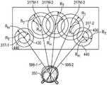
在一些示例中,一旦滤波模块800识别出眼睛运动的类型,就可以将眼睛运动的类型和眼睛跟踪数据(例如,包括用于进行确定的眼睛跟踪数据和在识别之后连续获得的附加眼睛跟踪数据)提供给注视预测模块802或辐辏预测模块804中的一个或两个。例如,当识别出眼跳、平滑追踪运动或前庭-眼部运动时,可将所识别出的运动类型和眼睛跟踪数据(例如,用于进行识别的眼睛跟踪数据和连续获得的附加眼睛跟踪数据)提供给注视预测模块802。在这些示例中,注视预测模块802然后确定一个或更多个预测的未来注视定位,以及针对预测的未来注视定位中的每一个的一个或更多个对应的置信水平。然后,可以从注视预测模块802向例如场景渲染模块720、聚焦预测模块708和/或人工现实引擎756提供预测注视定位和注视预测元数据(包括每个预测注视定位的置信水平),用于渲染(例如,预渲染)中央凹显示图像帧以用于由显示面板118显示。当识别出辐辏运动时,可将所识别的运动类型和眼睛跟踪数据(例如,用于进行识别的眼睛跟踪数据和连续获得的附加眼睛跟踪数据)提供给辐辏预测模块804。在这些示例中,辐辏预测模块804然后确定一个或更多个预测的未来辐辏平面或深度,以及针对预测的辐辏平面或深度中的每一个的一个或更多个对应的置信水平。然后,可以从辐辏预测模块804向例如场景渲染模块720、聚焦预测模块708、人工现实引擎756和/或辐辏处理模块712提供预测的辐辏平面和辐辏预测元数据(包括针对每个预测的辐辏平面的置信水平),以用于用显示组件360进行变焦显示。In some examples, once the type of eye movement is identified by thefiltering module 800, the type of eye movement and the eye tracking data (eg, including the eye tracking data used to make the determination and additional eye tracking data obtained continuously after the identification) may be ) is provided to one or both ofgaze prediction module 802 orvergence prediction module 804. For example, when a saccade, smooth tracking motion, or vestibulo-eye motion is identified, the identified motion type and eye tracking data (eg, eye tracking data for identification and additional eye tracking data obtained continuously) may be combined ) is provided to gazeprediction module 802. In these examples,gaze prediction module 802 then determines one or more predicted future gaze locations, and one or more corresponding confidence levels for each of the predicted future gaze locations. Predicted gaze locations and gaze prediction metadata (including a confidence level for each predicted gaze location) may then be provided fromgaze prediction module 802 to, for example,scene rendering module 720,focus prediction module 708, and/orartificial reality engine 756 for rendering A fovea display image frame is (eg, pre-rendered) for display bydisplay panel 118 . When vergence motion is identified, the identified type of motion and eye-tracking data (eg, eye-tracking data for the identification and additional eye-tracking data obtained sequentially) may be provided to thevergence prediction module 804 . In these examples, thevergence prediction module 804 then determines one or more predicted future vergence planes or depths, and one or more corresponding confidence levels for each of the predicted vergence planes or depths. The predicted vergence planes and vergence prediction metadata (including for each predicted vergence plane) may then be provided from thevergence prediction module 804 to, for example, thescene rendering module 720, thefocus prediction module 708, theartificial reality engine 756, and/or thevergence processing module 712. confidence level) for zoom display withdisplay assembly 360.

在上面的示例中,眼睛运动的类型以及注视定位和/或辐辏平面的预测是在单独的、不同的操作中执行的。然而,还应当理解,类型识别和预测可以在并行或部分并行操作中执行。例如,眼跳滤波器806、平滑追踪滤波器808、前庭-眼部滤波器810和辐辏滤波器812中的每一个可以用每个输入的眼睛跟踪测量值来生成和/或更新预测和置信水平。例如,随着每次试图将眼睛跟踪数据拟合或应用到眼跳模型,眼跳滤波器806可以生成置信水平和预测的注视定位,并且当该预测的置信水平高于预定阈值时输出基于眼跳的注视预测。在眼跳的示例中,尽管平滑追踪滤波器808、前庭-眼部滤波器810和辐辏滤波器812与眼跳滤波器806并行地生成预测,但这些预测将不被使用,因为眼睛跟踪数据将导致那些预测中的置信水平低于眼跳滤波器中的置信水平,并且随着附加数据而降低。In the above example, the type of eye movement and the prediction of gaze location and/or vergence plane are performed in separate, distinct operations. However, it should also be understood that type identification and prediction may be performed in parallel or partially parallel operations. For example, each ofsaccade filter 806,smooth tracking filter 808, vestibular-eye filter 810, andvergence filter 812 may use each input eye tracking measurement to generate and/or update predictions and confidence levels . For example, with each attempt to fit or apply eye tracking data to a saccade model, thesaccade filter 806 may generate a confidence level and a predicted gaze location, and output an eye-based gaze location when the predicted confidence level is above a predetermined threshold Jump gaze prediction. In the saccade example, althoughsmooth tracking filter 808, vestibular-eye filter 810, andvergence filter 812 generate predictions in parallel withsaccade filter 806, these predictions will not be used because the eye tracking data will Causes the confidence level in those predictions to be lower than that in the saccade filter and decrease with additional data.

还应理解,用于眼跳滤波器806、平滑追踪滤波器808、前庭-眼部滤波器810和辐辏滤波器812中的任一个或全部的模型可以在设备正常操作之前的训练会话中,和/或当模型随着时间的推移学习并适应每个用户的眼睛的行为时的头戴式显示设备102的正常使用期间,相对于头戴式显示设备102的每个用户进行调节。It should also be understood that the models for any or all of thesaccade filter 806,smooth pursuit filter 808, vestibular-ocular filter 810, andvergence filter 812 may be in a training session prior to normal operation of the device, and Adjustments are made relative to each user of the head mounteddisplay device 102 during normal use of the head mounteddisplay device 102 as the model learns and adapts over time to the behavior of each user's eyes.

在一些情形中,场景内容信息818还可以由滤波器806、808、810或812中的一个或更多个使用。例如,当滤波模块800识别出平滑追踪运动时,可以将呈现给用户的场景中的对象识别为被追踪的对象。在该情形中,由于场景中对象的运动是预先已知的,因此在视觉追踪该对象期间,可以将提前知道的知识应用于预测的未来注视定位。在另一示例中,在其中用户的眼睛在最近的视觉刺激(例如,爆炸,或游戏角色通过门进入)的方向上执行眼跳运动的情形中,最近的视觉刺激的定位可用于确定当前眼跳结束时的预测的注视定位(例如,通过向模型应用约束或附加输入数据点,以使预测眼睛会移动到最近的视觉刺激的定位的可能性更大)。场景内容信息818还可以被用于确定针对预测的注视定位和/或预测的辐辏平面的置信水平。例如,在活动的场景对象显示在预测的注视定位处或在其附近的情形中,针对该预测的注视定位的置信水平可以高于仅在预测的注视定位处显示背景的情形中的置信水平。In some cases,scene content information 818 may also be used by one or more offilters 806 , 808 , 810 or 812 . For example, objects in the scene presented to the user may be identified as tracked objects when smooth tracking motion is identified by thefiltering module 800 . In this case, since the motion of an object in the scene is known in advance, during visual tracking of the object, the knowledge known in advance can be applied to the predicted future gaze localization. In another example, in situations where the user's eyes perform saccades in the direction of the closest visual stimulus (eg, an explosion, or a game character entering through a door), the location of the closest visual stimulus can be used to determine the current eye Predicted fixation location at the end of the jump (eg, by applying constraints to the model or additional input data points to make it more likely that the predicted eye will move to the location of the closest visual stimulus). Thescene content information 818 may also be used to determine a confidence level for the predicted gaze location and/or the predicted vergence plane. For example, where an active scene object is displayed at or near a predicted gaze location, the confidence level for the predicted gaze location may be higher than that where the background is displayed only at the predicted gaze location.

在一些情形中,头部跟踪数据820(例如,来自跟踪模块754、IMU 716和/或头部跟踪传感器718)也可由滤波器806、808、810或812中的一个或更多个使用。例如,当滤波模块800识别出前庭-眼部运动时,头部跟踪数据可以被用于预测用户眼睛的即将发生的运动,以补偿头部跟踪数据指示的头部运动的一些或全部。由头部跟踪数据820指示的头部运动信息也可以被用于增强对眼跳运动、平滑追踪运动和/或辐辏运动的预测(例如,单独地使用或与用户校准数据816和/或场景内容信息818结合地使用)。In some cases, head tracking data 820 (eg, from tracking module 754 ,IMU 716 , and/or head tracking sensor 718 ) may also be used by one or more offilters 806 , 808 , 810 , or 812 . For example, when thefiltering module 800 identifies vestibulo-ocular motion, the head tracking data may be used to predict the imminent motion of the user's eyes to compensate for some or all of the head motion indicated by the head tracking data. Head motion information indicated byhead tracking data 820 may also be used to enhance prediction of saccade, smooth tracking, and/or vergence motion (eg, alone or withuser calibration data 816 and/or scene content).information 818 used in conjunction).

还应理解,虽然单独示出了注视预测模块802和辐辏预测模块804,但在一些实现中,注视预测和辐辏预测可以由公共模块执行和/或同时地执行(例如,通过基于识别的眼睛运动类型和眼睛跟踪数据预测三维注视定位)。It should also be understood that whilegaze prediction module 802 andvergence prediction module 804 are shown separately, in some implementations gaze prediction and vergence prediction may be performed by a common module and/or performed concurrently (eg, through recognition-based eye movement). type and eye-tracking data to predict 3D gaze localization).

图9示出了根据一个或更多个实现的用于诸如头戴式显示设备中的显示面板的电子显示器的预测性操作的示例过程的流程图。为了解释的目的,本文主要参考图1-图3和图5-图8中一个或更多个设备(特别是参考头戴式显示设备102、眼睛跟踪单元215、眼睛跟踪模块710、眼睛预测模块722、场景渲染模块720、辐辏处理模块712、变焦致动块706、显示组件360和显示面板118)描述图9的过程,其中一些过程可以由图1的头戴式设备102的一个或更多个处理器执行。然而,图9的过程不限于这些设备和/或模块,过程的一个或更多个块(或操作)可以由其他合适设备的一个或更多个其他部件执行。进一步为了解释的目的,本文图9的过程的块被描述为串行或线性地发生。然而,图9的过程的多个块可以并行发生。此外,图9的过程的块不需要以示出的顺序执行和/或图9的过程的一个或更多个块不需要被执行和/或可以由其他操作代替。9 illustrates a flowchart of an example process for predictive operation of an electronic display, such as a display panel in a head mounted display device, in accordance with one or more implementations. For purposes of explanation, reference is made herein primarily to one or more of the devices in FIGS. 1-3 and 5-8 (in particular with reference to head mounteddisplay device 102,eye tracking unit 215,eye tracking module 710,eye prediction module 722,scene rendering module 720,vergence processing module 712,zoom actuation block 706,display assembly 360, and display panel 118) describe the processes of FIG. 9, some of which may be performed by one or more of the head mounteddevice 102 of FIG. processor executes. However, the process of FIG. 9 is not limited to these devices and/or modules, and one or more blocks (or operations) of the process may be performed by one or more other components of other suitable devices. Further for purposes of explanation, blocks of the process of FIG. 9 are described herein as occurring serially or linearly. However, multiple blocks of the process of FIG. 9 may occur in parallel. Furthermore, blocks of the process of FIG. 9 need not be performed in the order shown and/or one or more blocks of the process of FIG. 9 need not be performed and/or may be replaced by other operations.

在块900处,获得预测的眼睛数据。对于佩戴头戴式显示设备(诸如头戴式显示设备102)的用户,预测的眼睛数据可以包括一个或更多个预测的注视定位和/或一个或更多个预测的辐辏平面或辐辏深度。每个预测的注视定位和每个预测的辐辏平面可以在未来具有相关联的预测时间,诸如与用于由显示面板118显示的即将到来的图像帧的显示时间相对应的预测时间。在一些示例中,可以针对下一个即将到来的图像帧和/或针对距当前显示帧的两个、三个、四个、五个、十个或更多个显示帧获得预测的眼睛数据。获得预测的眼睛数据可以包括利用例如图7和图8的眼睛预测模块722生成预测的眼睛数据。例如,结合图7和图8以及图10和图11的流程图,进一步详细描述了为获得预测的眼睛数据而可以被执行的操作的示例。Atblock 900, predicted eye data is obtained. For a user wearing a head mounted display device, such as head mounteddisplay device 102, the predicted eye data may include one or more predicted gaze locations and/or one or more predicted vergence planes or vergence depths. Each predicted gaze location and each predicted vergence plane may have an associated predicted time in the future, such as a predicted time corresponding to the display time for upcoming image frames displayed bydisplay panel 118 . In some examples, predicted eye data may be obtained for the next upcoming image frame and/or for two, three, four, five, ten or more display frames from the current display frame. Obtaining predicted eye data may include generating predicted eye data using, for example,eye prediction module 722 of FIGS. 7 and 8 . Examples of operations that may be performed to obtain predicted eye data are described in further detail, for example, in conjunction with the flowcharts of FIGS. 7 and 8 and FIGS. 10 and 11 .

在块902处,可以基于预测的眼睛数据来控制头戴式显示设备102的中央凹显示特征。例如,场景渲染模块720和/或AR引擎756可以生成(例如,预渲染)中央凹显示图像帧(例如图4的图像帧401)以用于由显示面板118显示,该图像帧具有围绕来自眼睛预测模块722的预测的注视定位的高分辨率区域。场景渲染模块720和/或AR引擎756可以基于例如与预测的注视定位相关联的置信水平来确定高分辨率区域和/或周围过渡区域和/或周边区域的大小和/或形状。结合例如图12-图18进一步详细描述了可以被执行用于基于预测的眼睛数据控制中央凹显示特征的操作的示例。Atblock 902, a foveal display characteristic of the head mounteddisplay device 102 may be controlled based on the predicted eye data. For example,scene rendering module 720 and/orAR engine 756 may generate (eg, pre-render) a foveal display image frame (eg,image frame 401 of FIG. 4 ) for display bydisplay panel 118 having a surrounding area from the eye The high-resolution region of the predicted gaze localization of theprediction module 722 . Thescene rendering module 720 and/or theAR engine 756 may determine the size and/or shape of the high-resolution area and/or surrounding transition area and/or surrounding area based on, for example, a confidence level associated with the predicted gaze localization. Examples of operations that may be performed to control foveal display features based on predicted eye data are described in further detail in conjunction with, eg, FIGS. 12-18 .

在块904处,可以基于预测的眼睛数据来控制诸如头戴式显示设备102的辐辏处理模块712和/或变焦致动块706的变焦系统。例如,当预测的眼睛数据包括不同于当前辐辏平面的预测的辐辏平面时,辐辏处理模块712可以操作变焦致动块706以移动或改变显示组件306的一个或更多个部件的形状(例如,通过移动或使薄饼透镜块中的透镜104中的一个变形)。在一些示例中,辐辏处理模块712可以确定与预测的辐辏平面相关联的舒适区,并修改显示组件的一个或更多个部件以将显示组件的图像平面移动到舒适区中。结合例如图19-图23进一步详细描述了可以被执行用于基于预测的眼睛数据控制中央凹显示特征的操作的示例。Atblock 904, a zoom system, such as thevergence processing module 712 and/or thezoom actuation block 706 of the head mounteddisplay device 102, may be controlled based on the predicted eye data. For example, when the predicted eye data includes a predicted vergence plane that is different from the current vergence plane, thevergence processing module 712 may operate thezoom actuation block 706 to move or change the shape of one or more components of the display assembly 306 (eg, by moving or deforming one of thelenses 104 in the pancake lens block). In some examples, thevergence processing module 712 may determine a comfort zone associated with the predicted vergence plane and modify one or more components of the display assembly to move the image plane of the display assembly into the comfort zone. Examples of operations that may be performed to control foveal display features based on predicted eye data are described in further detail in conjunction with, eg, FIGS. 19-23 .

图10示出了根据一个或更多个实现的用于获得预测的眼睛数据的示例过程的流程图。图10的过程的块在本文被描述为串行或线性地发生。然而,图10的过程的多个块可以并行发生。此外,图10的过程的块不需要以示出的顺序执行和/或图10的过程的一个或更多个块不需要被执行和/或可以由其他操作代替。10 illustrates a flowchart of an example process for obtaining predicted eye data, in accordance with one or more implementations. The blocks of the process of Figure 10 are described herein as occurring serially or linearly. However, multiple blocks of the process of Figure 10 may occur in parallel. Furthermore, blocks of the process of FIG. 10 need not be performed in the order shown and/or one or more blocks of the process of FIG. 10 need not be performed and/or may be replaced by other operations.

在块1000处,获得针对用户(诸如佩戴头戴式显示设备102的用户)的双眼的眼睛跟踪数据。可以通过在每个眼睛跟踪单元215中用红外光源照射用户的眼睛,以及在每个眼睛跟踪单元215中用红外相机捕获用户眼睛的红外图像来获得眼睛跟踪数据。可以处理眼睛跟踪数据以识别用户眼睛的一个或更多个特征,并识别每只眼睛的当前注视定位(例如,对应于用户的中央凹轴与显示面板118相交的定位处的定位),并识别每只眼睛的注视定位和/或中央凹轴的变化(例如,通过确定运动的当前方向和/或速度)。Atblock 1000, eye tracking data for both eyes of a user, such as a user wearing the head mounteddisplay device 102, is obtained. Eye tracking data may be obtained by illuminating the user's eyes with an infrared light source in eacheye tracking unit 215, and capturing an infrared image of the user's eyes with an infrared camera in eacheye tracking unit 215. The eye tracking data may be processed to identify one or more characteristics of the user's eyes, and to identify the current gaze location of each eye (eg, the location corresponding to the location where the user's foveal axis intersects the display panel 118), and to identify Changes in gaze location and/or foveal axis for each eye (eg, by determining the current direction and/or speed of motion).

在块1002处,基于眼睛跟踪数据确定眼睛运动的一种或更多种类型。眼睛运动的类型可以是例如当前正由头戴式显示设备102的用户的眼睛执行的眼跳、平滑追踪运动、前庭-眼部运动、辐辏运动或者这些眼睛运动类型中的两种或更多种的组合。可以基于在眼睛运动期间以及在眼睛运动完成之前的前两个、三个或几个眼睛跟踪数据点来确定眼睛运动的类型。确定眼睛运动的类型可以包括同时尝试将前几个眼睛跟踪数据点拟合或应用到针对每种眼睛运动类型的模型或被训练成将输入数据分类为眼睛运动的输出类型的组合的模型,确定针对眼睛运动的每种类型的置信水平,以及基于单独的置信水平和/或置信水平的比较来识别眼睛运动的一种或更多种类型。在一些情形中,可以基于眼睛跟踪数据指示眼睛运动的单一类型(例如,眼跳、平滑追踪运动、前庭-眼部运动或辐辏运动)。在其他情形中,用户的眼睛可以执行组合的运动(例如,眼跳到新深度处的对象,或者平滑地追踪后退或接近的对象),在这种情形中,可以识别两种并发的眼睛运动类型。在其他情形中,基于针对眼睛运动的每种类型的置信水平,眼睛运动的两种类型可以是可信的,在这种情况下,可以识别眼睛运动的两种类型。Atblock 1002, one or more types of eye movements are determined based on the eye tracking data. The type of eye movement may be, for example, saccade, smooth tracking movement, vestibulo-ocular movement, vergence movement, or two or more of these types of eye movement currently being performed by the eyes of the user of the head mounteddisplay device 102 The combination. The type of eye movement can be determined based on the first two, three or several eye tracking data points during the eye movement and before the eye movement is completed. Determining the type of eye movement may include simultaneously attempting to fit or apply the first few eye-tracking data points to a model for each type of eye movement or a model trained to classify input data into a combination of output types of eye movement, determining A confidence level for each type of eye movement, and one or more types of eye movement are identified based on individual confidence levels and/or comparisons of confidence levels. In some cases, a single type of eye motion (eg, saccade, smooth tracking motion, vestibulo-ocular motion, or vergence motion) may be indicated based on the eye tracking data. In other situations, the user's eyes may perform combined movements (eg, saccade to an object at a new depth, or smoothly track a receding or approaching object), in which case two concurrent eye movements may be identified type. In other cases, both types of eye movement may be plausible based on the confidence level for each type of eye movement, in which case both types of eye movement may be identified.

在块1004处,基于所确定的眼睛运动的一种或更多种类型、眼睛跟踪数据以及在识别了眼睛运动类型之后且在完成眼睛运动之前获得的附加眼睛跟踪数据点来确定预测的注视定位和/或预测的辐辏平面。例如,如果眼睛运动被确定为辐辏运动,则可以使用过去和/或当前注视方向和/或每只眼睛的注视方向的运动速度和方向来预测在眼睛运动结束时每只眼睛的注视方向,由此可以确定两只眼睛的定位的交叉点以识别辐辏深度或平面。作为另一示例,如果单个地识别出眼跳、平滑追踪或前庭-眼部运动中的任何一个,则可以将眼睛跟踪数据和附加的眼睛跟踪数据应用于该类型的眼睛运动的模型(例如,如针对特定用户所调节的),以确定当前眼部运动结束时的最终注视定位。作为另一示例,如果眼跳、平滑追踪和前庭-眼部运动中的两个或更多个被识别为对于由用户的眼睛当前正在执行的眼睛运动来说是可信的类型,则眼睛跟踪数据和附加的眼睛跟踪数据可以被应用于每种类型的眼睛运动的模型(例如,如针对特定用户所调节的),并且可以(例如,使用基于置信水平的加权平均值)组合所得到的预测以确定当前眼睛运动结束时的最终注视定位。预测的注视定位和/或预测的辐辏平面随后可以被用于控制设备的预测性中央凹显示和/或预测性变焦特征。At block 1004, a predicted gaze location is determined based on the determined one or more types of eye movement, eye tracking data, and additional eye tracking data points obtained after the eye movement type is identified and before the eye movement is completed and/or predicted vergence planes. For example, if the eye movement is determined to be a vergence movement, the past and/or current gaze direction and/or the movement speed and direction of each eye's gaze direction can be used to predict the gaze direction of each eye at the end of the eye movement, given by This can determine the intersection of the positioning of the two eyes to identify the vergence depth or plane. As another example, if any of saccade, smooth tracking, or vestibular-eye movement are individually identified, the eye-tracking data and additional eye-tracking data may be applied to a model of that type of eye movement (eg, as adjusted for a particular user) to determine the final fixation location at the end of the current eye movement. As another example, if two or more of saccade, smooth tracking, and vestibulo-eye movements are identified as plausible types of eye movements currently being performed by the user's eyes, eye tracking The data and additional eye tracking data can be applied to a model of each type of eye movement (eg, as adjusted for a particular user), and the resulting predictions can be combined (eg, using a weighted average based on confidence levels) to determine the final fixation location at the end of the current eye movement. The predicted gaze location and/or the predicted vergence plane may then be used to control the device's predictive foveal display and/or predictive zoom feature.

在一些情形中,预测的注视定位和/或预测的辐辏平面可以与眼睛运动类型的识别并行地确定。图11示出了根据一个或更多个实现的用于获得预测的眼睛数据的示例过程的流程图,其中可以看到各种并行处理方面。本文将图11的过程的一些块描述为与其他块串行发生,或线性地发生。然而,图11的过程的多个块可以并行发生。此外,图11的过程的块不需要以示出的顺序执行和/或图11的过程的一个或更多个块不需要被执行和/或可以由其他操作代替。In some cases, the predicted gaze location and/or the predicted vergence plane may be determined in parallel with the identification of eye movement types. 11 shows a flow diagram of an example process for obtaining predicted eye data in accordance with one or more implementations, in which various aspects of parallel processing can be seen. Some blocks of the process of FIG. 11 are described herein as occurring serially with other blocks, or linearly. However, multiple blocks of the process of FIG. 11 may occur in parallel. Furthermore, blocks of the process of FIG. 11 need not be performed in the order shown and/or one or more blocks of the process of FIG. 11 need not be performed and/or may be replaced by other operations.

在块1100处,使用安装到设备外壳的至少一个相机,获得针对用户(诸如佩戴头戴式显示设备102的用户)的双眼的眼睛跟踪数据。例如,眼睛跟踪数据可以使用两个红外相机来获得,每个红外相机捕获由安装在外壳中的红外光源照明的用户眼睛的图像。可以处理眼睛跟踪数据以识别用户眼睛的一个或更多个特征,识别每只眼睛的当前注视定位(例如,对应于用户的中央凹轴与显示面板118相交的定位处的定位),识别眼睛运动,识别注视定位的变化,和/或确定针对每只眼睛的注视定位和/或中央凹轴的运动的当前方向和/或速度。Atblock 1100, eye tracking data for both eyes of a user, such as a user wearing the head mounteddisplay device 102, is obtained using at least one camera mounted to the device housing. For example, eye tracking data may be obtained using two infrared cameras, each capturing an image of a user's eye illuminated by an infrared light source mounted in the housing. The eye tracking data may be processed to identify one or more characteristics of the user's eyes, identify the current gaze position of each eye (eg, the position corresponding to the position where the user's foveal axis intersects the display panel 118), identify eye movement , identify changes in gaze location, and/or determine the current direction and/or velocity of gaze location and/or movement of the foveal axis for each eye.

在块1102、1104、1106和1108处,头戴式显示设备中的处理电路可以并行地尝试识别当前可能正由用户眼睛执行的四种(或更多种)类型的眼睛运动。块1102、1104、1106和1108的操作可以例如分别由图8的滤波模块806、808、810和812执行。Atblocks 1102, 1104, 1106, and 1108, processing circuitry in the head mounted display device may attempt in parallel to identify four (or more) types of eye movements that may currently be performed by the user's eyes. The operations ofblocks 1102, 1104, 1106, and 1108 may be performed, for example, by filteringmodules 806, 808, 810, and 812 of FIG. 8, respectively.

在块1102处,可以基于眼睛跟踪数据并使用眼跳模型(例如,通过尝试将眼睛跟踪数据的特征拟合到经历眼跳的眼睛运动的相同特征的模型,或者通过提供眼睛跟踪数据作为机器学习眼跳模型的输入,该机器学习眼跳模型已被训练成响应于输入眼睛跟踪数据,输出预测的注视定位和预测的注视定位置信水平)来(例如,由眼跳滤波器806)确定第一预测的注视定位和第一注视定位置信水平。例如,通过将针对当前眼睛运动获得的前几个(例如,两个、三个或四个)速度(例如,速度和方向)测量值应用于针对一般用户的眼跳的典型速度测量值的模型或针对当前用户调节的速度测量值的模型(例如,并使用前几个速度测量值调节眼跳模型的参数),模型可以被用于输出未来时间的预测的注视定位。当前眼睛运动的加速度测量值(例如,其使用速度测量值确定)也可以或者可替代地应用于眼跳典型的加速度测量值的模型(例如,用于一般用户或针对当前用户调节的模型)。前几个速度测量值和/或加速度测量值的模型拟合的良好性或质量可以提供针对预测的注视定位的置信水平(例如,差的拟合将导致低置信水平,而好的拟合将导致高置信水平)。作为另一个示例,可以(例如,在眼睛预测模型722的眼跳滤波器806中)提供已经训练好的机器学习模型(例如,通过以下方式训练的:(i)将与用户和/或具有眼睛跟踪能力的设备的一个或更多个先前用户的已知眼跳运动相对应的眼睛跟踪数据提供给机器学习模型作为输入训练数据,(ii)将已知眼跳运动提供给机器学习模型作为输出训练数据,以及(iii)使用输入训练数据和输出训练数据调整模型的参数以生成经训练的模型)来输出用于新的眼睛跟踪数据的输入集合的预测注视定位和注视定位置信水平。在该机器学习示例中,例如,可以生成预测的注视定位和注视定位置信水平,而无需调整模型的参数以拟合当前的眼睛跟踪数据。当获得每个新的眼睛跟踪数据点时,可以更新预测、置信水平和/或模型参数。如果当前的眼睛运动确实是眼跳,则基于眼跳模型的预测的置信水平将随着每个增加的数据点而提高,并且预测的注视定位将趋向于最终预测。如果当前的眼睛运动不是眼跳,那么置信水平将随着每个增加的数据点而降低,因为从数据中可以更清楚地看出该运动不是眼跳。Atblock 1102, a saccade model can be used based on the eye-tracking data (eg, by attempting to fit features of the eye-tracking data to a model of the same features of eye movements that experience saccades, or by providing the eye-tracking data as machine learning input to a saccade model that has been trained to output a predicted gaze location and a predicted gaze location confidence level in response to input eye tracking data to determine (e.g., by the saccade filter 806) a first Predicted gaze localization and first gaze localization confidence levels. For example, by applying the first few (eg, two, three, or four) velocity (eg, speed and direction) measurements obtained for the current eye movement to a model of typical velocity measurements for a typical user's saccade Or a model of velocity measurements adjusted for the current user (eg, and using previous velocity measurements to adjust the parameters of the saccade model), the model can be used to output a predicted gaze location for future times. Acceleration measurements of current eye movement (eg, determined using velocity measurements) may also or alternatively be applied to models of acceleration measurements typical of saccades (eg, for a typical user or a model adjusted for the current user). The goodness or quality of the model fit of the first few velocity measurements and/or acceleration measurements can provide a confidence level for the predicted gaze location (eg, a poor fit will result in a low confidence level, while a good fit will leading to a high confidence level). As another example, an already trained machine learning model (eg, trained by (i) interacting with the user and/or having eyes Eye tracking data corresponding to known saccade movements of one or more previous users of the tracking capable device is provided to the machine learning model as input training data, (ii) the known saccade movements are provided to the machine learning model as output training data, and (iii) using the input training data and output training data to adjust the parameters of the model to generate a trained model) to output predicted gaze localization and gaze localization confidence levels for the input set of new eye tracking data. In this machine learning example, for example, predicted gaze localization and gaze localization confidence levels can be generated without adjusting the parameters of the model to fit current eye-tracking data. As each new eye tracking data point is obtained, predictions, confidence levels, and/or model parameters may be updated. If the current eye movement is indeed saccade, the confidence level of the prediction based on the saccade model will increase with each additional data point, and the predicted gaze localization will tend towards the final prediction. If the current eye movement is not a saccade, the confidence level will decrease with each additional data point, as it becomes clearer from the data that the movement is not a saccade.

在与块1102的操作并行的块1104处,可以基于眼睛跟踪数据和平滑追踪模型(例如,通过尝试将眼睛跟踪数据的特征拟合到经历平滑追踪的眼睛运动的相同特征的模型,或者通过提供眼睛跟踪数据作为机器学习平滑追踪模型的输入,该机器学习平滑追踪模型已被训练成响应于输入眼睛跟踪数据,输出预测的注视定位和预测的注视定位置信水平)来确定(例如,由平滑追踪滤波器808确定)第二预测的注视定位和第二注视定位置信水平。Atblock 1104, in parallel with the operations ofblock 1102, the eye-tracking data and a smooth-tracking model may be based on the eye-tracking data (eg, by attempting to fit features of the eye-tracking data to a model of the same features of eye motion undergoing smooth-tracking, or by providing eye-tracking data as input to a machine-learning smooth-tracking model that has been trained to output predicted gaze localization and predicted gaze-location confidence levels in response to input eye-tracking data (e.g., by smooth-tracking)Filter 808 determines) the second predicted gaze location and the second gaze location confidence level.

在与块1102和1104的操作并行的块1106处,可以基于眼睛跟踪数据并假设用户的当前眼睛运动是前庭-眼部运动来(例如,由前庭-眼部滤波器810)确定第三预测的注视定位和第三注视定位置信水平(例如,通过尝试将眼睛跟踪数据和/或头部跟踪的特征拟合到经历前庭-眼部运动的眼睛运动的相同特征的模型,或者通过提供眼睛跟踪数据和/或头部跟踪数据作为机器学习前庭-眼部模型的输入来确定,该机器学习前庭-眼部模型已经被训练成响应于输入眼睛跟踪数据而输出预测的注视定位和预测的注视定位置信水平)。Atblock 1106 parallel to the operations ofblocks 1102 and 1104, a third predicted third may be determined (eg, by the vestibulo-ocular filter 810) based on the eye tracking data and assuming that the user's current eye movement is vestibular-ocular movement Gaze localization and third gaze localization confidence levels (for example, by attempting to fit the features of eye tracking data and/or head tracking to a model of the same features of eye movement undergoing vestibular-eye movement, or by providing eye tracking data and/or head tracking data is determined as input to a machine learning vestibular-eye model that has been trained to output predicted gaze localization and predicted gaze localization information in response to input eye tracking data. Level).

在与块1102、1104和1106的操作并行的块1108处,可以基于眼睛跟踪数据并假设用户的当前眼睛运动是辐辏运动来(例如,由辐辏滤波器812)确定预测的辐辏平面和辐辏平面置信水平(例如,通过尝试将眼睛跟踪数据的特征拟合到经历辐辏运动的眼睛运动的相同特征的模型,或者通过提供眼睛跟踪数据作为机器学习辐辏模型的输入来确定,该机器学习辐辏模型已经被训练成响应于输入眼睛跟踪数据而输出预测的注视定位和预测的注视定位置信水平)。Atblock 1108, in parallel with the operations ofblocks 1102, 1104, and 1106, a predicted vergence plane and vergence plane confidence may be determined (eg, by vergence filter 812) based on the eye tracking data and assuming that the user's current eye movement is vergence movement level (for example, determined by attempting to fit features of eye-tracking data to a model of the same features of eye movements undergoing vergence motion, or by providing eye-tracking data as input to a machine-learning vergence model that has been trained to output a predicted gaze location and a predicted gaze location confidence level in response to input eye tracking data).

还可以针对头戴式显示设备102的一个或更多个特定用户中的每一个来调节结合块1102、1104、1106和1108描述的模型。例如,在用户在使用头戴式显示设备102期间执行的眼睛运动之后,可以将该眼睛运动所产生的眼睛跟踪数据、预测的注视定位、预测的辐辏平面、实际注视定位和/或实际辐辏平面反馈到模型(例如,作为附加训练数据),以进一步微调针对每个用户的模型。以这种方式,模型可以学习和适应每个用户的特定的眼睛行为。The models described in connection withblocks 1102 , 1104 , 1106 , and 1108 may also be adjusted for each of one or more specific users of the head mounteddisplay device 102 . For example, eye tracking data, predicted gaze location, predicted vergence plane, actual gaze location, and/or actual vergence plane resulting from the eye movement may be followed by eye movements performed by the user during use of the head mounteddisplay device 102 Feedback to the model (e.g., as additional training data) to further fine-tune the model for each user. In this way, the model can learn and adapt to each user's specific eye behavior.

在块1110处,眼睛预测模块722可以确定第一注视定位置信水平、第二注视定位置信水平或第三注视定位置信水平中的任何一个是否高于置信水平阈值。置信水平阈值可以是与第一注视定位置信水平、第二注视定位置信水平和第三注视定位置信水平中的每一个共同比较的预定阈值,或者可以是基于当前注视定位置信水平变化的动态置信水平。例如,在块1110处,当第一注视定位置信水平、第二注视定位置信水平或第三注视定位置信水平中的任何一个上升到高于公共置信水平阈值时,与该置信水平相关联的眼睛运动的类型可以被标识为用户当前正在执行的眼睛运动的类型。在另一示例中,当第一注视定位置信水平、第二注视定位置信水平或第三注视定位置信水平中的任一个上升到高于第一注视定位置信水平、第二注视定位置信水平和第三注视定位置信水平和/或辐辏平面置信水平中的另两个时,与该置信水平相关联的眼睛运动的类型可被识别为用户当前正在执行的眼睛运动的类型。Atblock 1110, theeye prediction module 722 may determine whether any of the first fixation confidence level, the second fixation confidence level, or the third fixation confidence level is above a confidence level threshold. The confidence level threshold may be a predetermined threshold that is compared with each of the first, second, and third gaze-location confidence levels, or may be a dynamic confidence level based on changes in the current gaze-location confidence level. . For example, atblock 1110, when any of the first fixation confidence level, the second fixation confidence level, or the third fixation confidence level rises above a common confidence level threshold, the eye associated with that confidence level The type of movement may be identified as the type of eye movement the user is currently performing. In another example, when any of the first gaze fixation confidence level, the second gaze fixation confidence level, or the third gaze fixation confidence level rises above the first gaze fixation confidence level, the second gaze fixation confidence level, and the third When looking at the other two of the fixation confidence level and/or the vergence plane confidence level, the type of eye movement associated with that confidence level may be identified as the type of eye movement the user is currently performing.

在块1112处,眼睛预测模块722还可以确定辐辏平面置信水平是否高于辐辏平面置信水平阈值。如果辐辏平面置信水平高于辐辏平面置信水平阈值,则眼睛预测模块722可以确定用户的当前眼睛运动是辐辏运动。例如,可以通过确定用户的两只眼睛水平地在不同(例如,相反)方向上移动来确定辐辏运动。Atblock 1112, theeye prediction module 722 may also determine whether the vergence plane confidence level is above the vergence plane confidence level threshold. If the vergence plane confidence level is above the vergence plane confidence level threshold, theeye prediction module 722 may determine that the user's current eye movement is a vergence movement. For example, vergence motion may be determined by determining that the user's two eyes are moving horizontally in different (eg, opposite) directions.

因为在图11的示例中,对于每个注视定位置信水平生成预测的注视定位,并且在识别眼睛运动的类型的同时对于每个预测的辐辏平面生成辐辏平面,所以在识别眼睛运动的时候,已准备好将对应的注视定位和/或辐辏平面提供给其他部件以用于中央凹显示和/或变焦操作。Since, in the example of FIG. 11, a predicted gaze localization is generated for each gaze localization confidence level, and a vergence plane is generated for each predicted vergence plane while identifying the type of eye movement, when recognizing eye movements, the Be prepared to provide corresponding gaze localization and/or vergence planes to other components for foveal display and/or zoom manipulation.

例如,在块1114处,如果第一注视定位置信水平、第二注视定位置信水平或第三注视定位置信水平中的任一个高于置信水平阈值,则可以将对应的第一预测的注视定位、第二预测的注视定位或第三预测的注视定位连同高于阈值的注视定位置信水平提供给场景渲染模块720和/或人工现实引擎756,以用于预测性中央凹显示操作。在一些情形中,在块1114处,(例如,如果要在预测定位处显示的显示内容位于与用户当前定位处的显示内容不同的深度处,诸如,如果用户的眼睛从对应于远处对象的注视定位朝向用户前面的桌子向下移动)还可以将预测的注视定位提供给辐辏处理模块712。以这种方式,变焦部件可以预测性地移动以预期尚未开始的辐辏变化。For example, atblock 1114, if any of the first gaze fixation confidence level, the second gaze fixation confidence level, or the third gaze fixation confidence level is above the confidence level threshold, the corresponding first predicted fixation confidence level, The second predicted gaze fixation or the third predicted fixation fix, along with a gaze fixation confidence level above a threshold, is provided to thescene rendering module 720 and/or theartificial reality engine 756 for predictive foveal display operations. In some cases, atblock 1114, (eg, if the display content to be displayed at the predicted location is at a different depth than the display content at the user's current location, such as if the user's eyes are drawn from a distance corresponding to a distant object, The gaze location moves down toward the table in front of the user) The predicted gaze location can also be provided to thevergence processing module 712. In this way, the zoom member can move predictively in anticipation of vergence changes that have not yet begun.

例如,在块1116处,如果辐辏平面置信水平高于辐辏平面置信水平阈值,则可将对应的预测的辐辏平面连同辐辏平面置信水平提供给辐辏处理模块712和/或聚焦预测模块708,用于预测性变焦操作。For example, atblock 1116, if the vergence plane confidence level is above the vergence plane confidence level threshold, the corresponding predicted vergence plane may be provided to thevergence processing module 712 and/or thefocus prediction module 708 along with the vergence plane confidence level for use by thevergence processing module 712 and/or thefocus prediction module 708 Predictive zoom action.

在注视定位和辐辏平面都在变化的情况下,可以在块1114处提供一个或更多个预测的注视定位,并且可以在块1116处提供一个或更多个预测的辐辏平面。Where both the gaze location and the vergence plane are changing, one or more predicted gaze locations may be provided atblock 1114 and one or more predicted vergence planes may be provided atblock 1116 .

示例预测性中央凹显示系统和方法Example predictive foveal display systems and methods

图12示出了根据一个或更多个实现的用于预测性中央凹显示的示例过程的流程图。为了解释的目的,本文主要参考图1-图3和图7-图8的一个或更多个设备(特别是参考头戴式显示设备102、眼睛跟踪单元215、眼睛跟踪模块710、眼睛预测模块722、场景渲染模块720、显示组件360和显示面板110)描述图12的过程,其中一些过程可以由图1的头戴式设备102的一个或更多个处理器执行。然而,图12的过程不限于这些设备和/或模块,过程的一个或更多个块(或操作)可以由其他合适设备的一个或更多个其他部件执行。进一步为了解释的目的,图12的过程的块在本文中被描述为串行或线性地发生。然而,图12的过程的多个块可以并行发生。此外,图12的过程的块不需要以示出的顺序执行和/或图12的过程的一个或更多个块不需要被执行和/或可以由其他操作代替。12 shows a flowchart of an example process for predictive foveal display in accordance with one or more implementations. For purposes of explanation, reference is made herein primarily to one or more of the devices of FIGS. 1-3 and 7-8 (in particular with reference to head mounteddisplay device 102,eye tracking unit 215,eye tracking module 710,eye prediction module 722,scene rendering module 720,display component 360, and display panel 110) describe the processes of FIG. 12, some of which may be performed by one or more processors of the head mounteddevice 102 of FIG. However, the process of FIG. 12 is not limited to these devices and/or modules, and one or more blocks (or operations) of the process may be performed by one or more other components of other suitable devices. Further for purposes of explanation, the blocks of the process of FIG. 12 are described herein as occurring serially or linearly. However, multiple blocks of the process of FIG. 12 may occur in parallel. Furthermore, blocks of the process of FIG. 12 need not be performed in the order shown and/or one or more blocks of the process of FIG. 12 need not be performed and/or may be replaced by other operations.

在块1200处,获得一个或更多个预测的注视定位。可以基于例如图10或图11的操作从例如眼睛预测模块722获得预测的注视定位。预测的注视定位可以包括一帧的预测、三帧的预测和十帧的预测(作为示例),它们对应于从当前显示的帧开始的未来一帧、未来三帧或未来十帧的预测时间。每个预测的注视定位具有也可以获得的相关联的置信水平。Atblock 1200, one or more predicted gaze locations are obtained. The predicted gaze location may be obtained, for example, fromeye prediction module 722 based on, for example, the operations of FIG. 10 or FIG. 11 . Predicted gaze localization may include one-frame prediction, three-frame prediction, and ten-frame prediction (as examples), which correspond to predicted times one, three, or ten frames in the future from the currently displayed frame. Each predicted gaze location has an associated confidence level that can also be obtained.

在块1202处,场景渲染模块720、AR引擎756和/或头戴式显示设备102的其他处理电路和/或控制台750基于预测的注视定位及其相关联的注视定位置信水平中的一个或更多个来确定即将到来的图像帧的高分辨率区域的定位(例如,中心)、大小和/或形状。Atblock 1202, thescene rendering module 720,AR engine 756 and/or other processing circuitry of the head mounteddisplay device 102 and/or theconsole 750 is based on one of the predicted gaze location and its associated gaze location belief level or More to determine the location (eg, center), size, and/or shape of the high-resolution region of the upcoming image frame.

例如,高分辨率区域可以是以预测的注视定位为中心并由同心的矩形或圆形的过渡区域到周围的周边区域所包围的矩形或圆形高分辨率区域。在该示例中,高分辨率区域和过渡区域的宽度或半径可以基于置信水平(例如,与置信水平成反比地)确定。以这种方式,当预测的确定性相对较低时,在预测的注视定位处生成相对较大的高分辨率区域。然而,针对图像帧的矩形或圆形区域的示例仅仅是说明性的。For example, the high-resolution region may be a rectangular or circular high-resolution region centered on the predicted fixation location and surrounded by a concentric rectangular or circular transition region to the surrounding perimeter region. In this example, the width or radius of the high resolution region and the transition region may be determined based on the confidence level (eg, inversely proportional to the confidence level). In this way, a relatively large high-resolution region is generated at the predicted fixation location when the certainty of the prediction is relatively low. However, the example for a rectangular or circular area of an image frame is merely illustrative.

高分辨率区域、过渡区域和/或周边区域的形状也可以基于注视定位置信水平来确定。例如,高分辨率区域和/或过渡区域可以沿着用户注视的运动方向伸长,(例如)伸长量与置信水平成反比。例如,当针对预测的注视定位的置信水平相对较低时,高分辨率区域和/或过渡区域可以具有沿运动方向的相对较大的伸长。随着针对预测的注视定位的置信水平提高,伸长可以减小(例如,针对高于上阈值的置信水平,或者针对当前(测量的)注视定位,减小到正方形或者圆形形状)。伸长可以是关于预测的注视定位对称的,或者可以具有不对称性(例如,恒定不对称性或与置信水平成反比的不对称性)。高分辨率区域(例如,中央凹区域)的大小和/或形状可以随着预测模型建立置信度而动态变化,如结合例如图13-图18进一步详细描述的。The shape of the high-resolution area, transition area, and/or peripheral area may also be determined based on the level of gaze fixation confidence. For example, the high-resolution region and/or the transition region may be elongated in the direction of motion of the user's gaze, eg, by an amount that is inversely proportional to the confidence level. For example, when the confidence level for the predicted gaze localization is relatively low, the high-resolution region and/or transition region may have a relatively large elongation in the direction of motion. As the confidence level for the predicted gaze location increases, the elongation may decrease (eg, to a square or circular shape for a confidence level above an upper threshold, or for the current (measured) gaze location). Elongation can be symmetric about the predicted gaze location, or can have asymmetry (eg, constant asymmetry or asymmetry that is inversely proportional to the confidence level). The size and/or shape of the high-resolution region (eg, the foveal region) may vary dynamically as the predictive model builds confidence, as described in further detail in connection with, eg, FIGS. 13-18 .

在渲染之前,随着获得附加的眼睛跟踪数据,针对每个预测的注视定位的置信水平可以提高(或降低),并且针对每个预测的高分辨率区域430和过渡区域440的大小和/或形状可以相应地修改。例如,在针对一帧预测的注视定位、三帧预测的注视定位和十帧预测的注视定位中的每一个的置信水平随着输入的眼睛跟踪数据而上升时,与每个预测相关联的高分辨率区域430和过渡区域440的大小可以减小。Prior to rendering, as additional eye-tracking data is obtained, the confidence level for each predicted gaze localization may be increased (or decreased), and the size and/or size of the high-resolution region 430 andtransition region 440 for each predicted The shape can be modified accordingly. For example, as the confidence level for each of the one-frame predicted gaze localization, the three-frame predicted gaze localization, and the ten-frame predicted gaze localization rises with the input eye-tracking data, the high value associated with each prediction increases. The size of theresolution region 430 and thetransition region 440 may be reduced.

在块1204处,可以渲染图像帧的第一内容以在具有所确定的定位、大小和/或形状的高分辨率区域中(例如,使用显示面板118)显示。高分辨率区域中的第一内容可以以相对高(例如,中央凹)分辨率渲染。围绕第一内容的第二内容可以被渲染用于在过渡区域中显示,该过渡区域具有针对过渡区域所确定的大小和/或形状,并且分辨率从高分辨率区域的边界处的高分辨率降低到周边区域的边界处的较低分辨率。可以渲染围绕第二内容的第三内容,以便在周边区域中以相对低的分辨率显示。以这种方式,在用户的眼睛运动到未来注视定位时,可以提供图像帧的中央凹显示,其中高分辨率区域在针对用户眼睛的未来注视定位处被预渲染。渲染的中央凹显示图像帧可以被存储以用于以后的显示和/或用于在显示之前的更新或修改,和/或可以在用户的眼睛朝着预测的注视定位运动时被显示。例如,因为一旦启动眼跳运动,用户就不能重定向眼跳,并且眼跳期间的视觉感知可能会降低(例如,因为眼睛在快速眼睛运动或焦点移动期间不会感知到大量细节),所以当识别出眼跳运动和相关联的未来注视定位时,在用户的眼睛到达预测的未来注视定位之前,可以显示和/或调整预测的未来注视定位处的具有高分辨率区域的中央凹显示图像帧。在其他情况下,在预测的未来注视定位处的具有高分辨率区域的中央凹显示图像帧可以被预渲染并存储以用于当眼睛的当前运动完成时进行显示。在一些情况下,渲染的和/或显示的图像帧的高分辨率区域的大小可以在渲染之后增大(例如,基于不同于预测注视定位的新的预测注视定位处的更新的预测而增大,由于不同于预测注视定位的当前注视定位和/或由于预测注视定位的置信度降低),以确保用户的眼睛落在高分辨率区域中。在一些情况下,可以首先渲染周边(低分辨率)区域400,稍后基于新更新的眼睛跟踪数据添加高分辨率区域。Atblock 1204, the first content of the image frame may be rendered for display in a high-resolution area having the determined positioning, size, and/or shape (eg, using display panel 118). The first content in the high-resolution region may be rendered at a relatively high (eg, foveal) resolution. The second content surrounding the first content may be rendered for display in a transition area, the transition area having a size and/or shape determined for the transition area and at a resolution from the high resolution at the boundaries of the high resolution area Down to a lower resolution at the border of the surrounding area. The third content surrounding the second content may be rendered for display at a relatively low resolution in the surrounding area. In this way, as the user's eyes move to the future fixation location, a foveal display of the image frame can be provided, with high resolution regions pre-rendered at the future fixation location for the user's eyes. The rendered foveal display image frames may be stored for later display and/or for updating or modification prior to display, and/or may be displayed as the user's eyes move toward the predicted gaze location. For example, because users cannot redirect saccades once saccades are initiated, and visual perception during saccades may be reduced (eg, because the eyes do not perceive a great deal of detail during rapid eye movements or focus shifts), when When the saccade movement and associated future fixation location are identified, a foveal display image frame with a high resolution region at the predicted future fixation location may be displayed and/or adjusted before the user's eyes reach the predicted future fixation location . In other cases, a foveal display image frame with a high-resolution region at the predicted future fixation location may be pre-rendered and stored for display when the current movement of the eye is complete. In some cases, the size of the high-resolution region of the rendered and/or displayed image frame may be increased after rendering (eg, based on an updated prediction at a new predicted gaze location other than the predicted gaze location) , due to the current gaze location being different from the predicted gaze location and/or due to reduced confidence in the predicted gaze location) to ensure that the user's eyes fall in the high-resolution region. In some cases, peripheral (low resolution)regions 400 may be rendered first, with high resolution regions added later based on newly updated eye tracking data.

在块1206处,下一显示帧的高分辨率区域的大小和/或形状可以相对于渲染的和/或显示的图像帧的大小和/或形状进行修改。例如,当用户的眼睛仍然朝着渲染的和/或显示的图像帧的预测的未来注视定位运动时,由于获得附加的眼睛跟踪数据,针对预测的注视定位的置信水平可以提高,从而允许下一显示帧的高分辨率区域(和/或周围的过渡区域)的大小减小。当用户的眼睛接近预测的注视定位时,高分辨率区域(和/或周围的过渡区域)的形状也可以随着置信水平的提高而变化(例如,变得更对称和/或更圆)。Atblock 1206, the size and/or shape of the high-resolution region of the next display frame may be modified relative to the size and/or shape of the rendered and/or displayed image frame. For example, while the user's eyes are still moving towards the predicted future fixation location of the rendered and/or displayed image frame, the confidence level for the predicted fixation location may be increased due to the acquisition of additional eye tracking data, allowing the next The size of the high-resolution area of the display frame (and/or the surrounding transition area) is reduced. The shape of the high-resolution region (and/or the surrounding transition region) may also change (eg, become more symmetrical and/or rounded) as the confidence level increases as the user's eyes approach the predicted gaze location.

在块1208处,可以确定静态或当前注视定位。例如,在用户的眼睛运动完成之后,并且用户的注视已经(至少暂时地)落在静态注视定位处,可以使用例如最新的(最近的)眼睛跟踪数据点来识别当前的静态注视定位。静态注视定位可以在先前获得的预测未来注视定位处或附近。Atblock 1208, a static or current gaze location may be determined. For example, after the user's eye movement is complete, and the user's gaze has fallen (at least temporarily) at a static gaze location, the current static gaze location can be identified using, for example, the most recent (most recent) eye tracking data points. The static gaze localization may be at or near previously obtained predicted future gaze localizations.

在块1210处,因为现在已知用户的注视定位(例如,因为该定位在最近测量的定位处是静态的),所以可以进一步将高分辨率区域的大小减小到当注视定位是静态时要显示的中央凹显示帧的最小大小。如图12的操作所示,预测的注视定位和对应的置信水平允许中央凹显示操作的各个方面提前和/或与其他场景内容识别和渲染操作并行地执行,使得中央凹显示图像帧可以在用户的眼睛到达新定位之前生成,从而减少系统延迟的影响并防止用户的视觉错误或中断。Atblock 1210, since the user's gaze location is now known (eg, because the location was static at the most recently measured location), the size of the high-resolution region can be further reduced to the point where the gaze location is static. The minimum size of the displayed fovea display frame. As shown in the operations of Figure 12, the predicted gaze location and corresponding confidence levels allow various aspects of foveal display operations to be performed in advance and/or in parallel with other scene content recognition and rendering operations, so that foveal display image frames can be generated before the eye reaches a new location, reducing the impact of system latency and preventing user visual errors or interruptions.

图13-图18示出了根据本公开的方面的在预测性中央凹显示操作期间显示面板118的各种视图。例如,在图13中,显示面板118被示出为显示针对当前静态注视定位317的中央凹显示图像帧401。在图13-图18的示例中,仅为了当前讨论的清楚性而省略光学块320及其光学效果,但应当理解,该光学块320插入在用户眼睛和设备102中的显示面板118之间。13-18 illustrate various views of thedisplay panel 118 during predictive foveal display operations in accordance with aspects of the present disclosure. For example, in FIG. 13 ,display panel 118 is shown displaying a foveadisplay image frame 401 for the currentstatic gaze position 317 . In the examples of FIGS. 13-18 , theoptical block 320 and its optical effects are omitted only for clarity of the present discussion, but it should be understood that theoptical block 320 is interposed between the user's eye and thedisplay panel 118 in thedevice 102 .

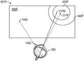
在图13的示例中,注视定位317是基于来自眼睛跟踪单元215和眼睛跟踪模块710的注视方向506的最近测量值的当前静态注视定位。在该示例中,中央凹显示图像帧401的高分辨率区域430和过渡区域440是圆形的,并且具有作为这些区域在中央凹显示操作中的最小宽度的各自的宽度RH和RT(本示例中的半径)。尽管在图13的示例中,中央凹显示图像帧401的高分辨率区域430和过渡区域440是圆形的,但是应当理解,诸如矩形形状的其他形状可以用于中央凹显示图像帧401的高分辨率区域430和过渡区域440。In the example of FIG. 13 ,gaze location 317 is the current static gaze location based on the most recent measurements ofgaze direction 506 fromeye tracking unit 215 andeye tracking module 710 . In this example,high resolution region 430 andtransition region 440 of fovealdisplay image frame 401 are circular and have respective widthsRH and RT( radius in this example). Although in the example of FIG. 13 thehigh resolution area 430 andtransition area 440 of the fovealdisplay image frame 401 are circular, it should be understood that other shapes such as rectangular shapes may be used for the height of the fovealdisplay image frame 401Resolution area 430 andtransition area 440 .

图14示出了其中用户的眼睛350已经开始从图13的注视定位317(在图14中标记为先前的注视定位1400)朝向新的未知的注视定位进行眼跳运动的示例。在图14的示例中,眼睛350具有以速度S在方向D上改变的当前注视定位317M。方向D和速度S可以基于例如用户瞳孔和/或用户眼睛的其他识别部分的运动的眼睛跟踪数据点1402(例如,测量值)来确定。可以用收集的每个数据点1402测量和/或更新方向D和速度S。如图14所示,基于方向D和速度S(例如,其与眼睛运动的已完成部分相关联的一个或多更个测量值),生成(例如,由眼睛预测模块722生成)预测的注视定位317P。还应当理解,在各种时间(例如,其对应于用户眼睛的注视方向的变化)的眼睛跟踪数据点1402(例如,测量值)可以被用于生成预测的注视定位317P,而无需明确地输出速度S或方向D的测量值。FIG. 14 shows an example where the user'seyes 350 have begun saccades fromgaze location 317 of FIG. 13 (labeled asprevious gaze location 1400 in FIG. 14 ) toward a new, unknown gaze location. In the example of FIG. 14 ,eye 350 has acurrent gaze location 317M changing in direction D at speed S. The direction D and speed S may be determined based on eye tracking data points 1402 (eg, measurements) such as the movement of the user's pupils and/or other identified parts of the user's eyes. Direction D and speed S may be measured and/or updated with eachdata point 1402 collected. As shown in FIG. 14, based on direction D and velocity S (eg, one or more measurements of which are associated with the completed portion of eye movement), a predicted gaze location is generated (eg, by eye prediction module 722) 317P. It should also be appreciated that eye tracking data points 1402 (eg, measurements) at various times (eg, corresponding to changes in the gaze direction of the user's eyes) can be used to generate predictedgaze locations 317P without explicitly outputting A measurement of speed S or direction D.

如上所讨论的(参见,例如,图9-图11),以一置信水平生成预测的注视定位317P,该置信水平可以被用于确定在用户的眼睛到达预测的注视定位时或之前要显示的图像帧的高分辨率区域430和过渡区域440的大小和形状。在图14的示例中,由于在用户眼睛运动的这个阶段对于预测的注视定位317P的相对低的置信水平,预测性中央凹显示图像帧401P被显示有比图13的高分辨率区域430大的高分辨率区域430P,并且沿着注视定位317M的运动方向伸长。在图14的示例中,由于在用户眼睛运动的这个阶段对于预测的注视定位317P的相对低的置信水平,过渡区域440P也比图13的过渡区域440大,并且沿着注视定位317M的运动方向伸长。相应地确定周边部分400P的大小和形状。As discussed above (see, eg, FIGS. 9-11 ), the predictedgaze location 317P is generated with a confidence level that can be used to determine what to display when or before the user's eyes reach the predicted gaze location The size and shape of thehigh resolution area 430 andtransition area 440 of the image frame. In the example of FIG. 14, the predictive fovealdisplay image frame 401P is displayed with a larger size than thehigh resolution area 430 of FIG. 13 due to the relatively low confidence level in the predictedgaze location 317P at this stage of the user's eye movementHigh resolution region 430P, and is elongated along the direction of motion ofgaze location 317M. In the example of FIG. 14, thetransition area 440P is also larger than thetransition area 440 of FIG. 13 due to the relatively low confidence level in the predictedgaze location 317P at this stage of the user's eye movement, and is along the direction of movement of thegaze location 317M elongation. The size and shape of theperipheral portion 400P are determined accordingly.

图15示出了其中用户的眼睛350已经完成了从先前注视定位1400朝向预测的注视定位317P的大部分眼跳运动的示例。如图15所示,已经获得了更多的眼睛跟踪数据点1402,允许以比图14时的置信水平相对更高的置信水平来生成预测的注视定位317P。因此,在图15时,显示的图像帧中的高分辨率区域430P和过渡区域440P的大小相对于在图14时显示的图像帧中的那些区域的大小减小,并且由于图15预测的更高置信水平,高分辨率区域430P和过渡区域440P具有沿注视定位317M的运动的减小的伸长。15 shows an example where the user'seyes 350 have completed most of the saccade movement from theprevious gaze location 1400 toward the predictedgaze location 317P. As shown in FIG. 15 , more eye trackingdata points 1402 have been obtained, allowing the predictedgaze location 317P to be generated with a relatively higher confidence level than that of FIG. 14 . Therefore, at the time of Figure 15, the size of the high-resolution region 430P and thetransition region 440P in the displayed image frame is reduced relative to the size of those regions in the displayed image frame at the time of Figure 14, and due to the larger size predicted by Figure 15 High confidence level, high-resolution region 430P andtransition region 440P have reduced elongation of motion alonggaze location 317M.

图16示出了其中眼跳运动完成并且用户的注视方向506已经落在注视定位317并且静止在新的注视定位317处的示例。在该示例中,新的注视定位317接近但不恰好在先前预测的注视定位317P的定位处。在该示例中,因为注视定位317再次是静态的,所以高分辨率区域430和过渡区域440是对称的(例如,在该说明性示例中是圆形的)、同心的,并且分别具有最小宽度RH和RTFIG. 16 shows an example where the saccade movement is complete and the user'sgaze direction 506 has fallen on thegaze location 317 and is stationary at thenew gaze location 317 . In this example, thenew gaze location 317 is near but not exactly at the location of the previously predictedgaze location 317P. In this example, becausegaze location 317 is again static, high-resolution region 430 andtransition region 440 are symmetrical (eg, circular in this illustrative example), concentric, and each have a minimum widthRH and RT.

图17示出了根据本公开的方面的在用户眼睛的平滑追踪运动期间的预测性中央凹显示操作期间的显示面板118。例如,在图17中,显示面板118被示出为在用户的注视定位变化以执行从第一静态注视定位317-1(移动通过中间注视定位317M-1、317M-2和317M-3)到第二静态注视定位317-2的平滑追踪运动时显示中央凹显示图像帧。在图17的示例中,注视定位317-1和317-2各自是基于来自眼睛跟踪单元215和眼睛跟踪模块710的注视方向506-1和506-2的最近测量值的当前静态注视定位。因此,中央凹显示图像帧401的高分辨率区域430和过渡区域440具有各自的宽度RH和RT(例如,在图17的示例中的半径),该宽度RH和RT是在用户眼睛的平滑追踪运动之前和之后用于中央凹显示操作的这些区域的最小宽度。17 illustratesdisplay panel 118 during a predictive foveal display operation during smooth tracking motion of a user's eye, in accordance with aspects of the present disclosure. For example, in Figure 17,display panel 118 is shown as the user's gaze location changes to perform a transition from a first static gaze location 317-1 (moving throughintermediate gaze locations 317M-1, 317M-2, and 317M-3) to A fovea display image frame is displayed while the smooth tracking motion of the second static gaze position 317-2 is displayed. In the example of FIG. 17 , gaze locations 317 - 1 and 317 - 2 are each a current static gaze location based on the most recent measurements of gaze directions 506 - 1 and 506 - 2 fromeye tracking unit 215 andeye tracking module 710 . Accordingly, the high-resolution region 430 andtransition region 440 of the foveadisplay image frame 401 have respective widthsRH and RT( eg,radii in the example of FIG. 17) that are The minimum width of these regions for foveal display operations before and after smooth tracking motion of the eye.

如图17所示,当检测到平滑追踪运动时,因为用户的眼睛的运动比图13-图16中所示的眼跳运动慢,并且可以以更高的置信水平来预测(例如,特别是,如果对应于显示对象的已知运动的已知显示内容可以与追踪相关联),移动和/或预测的注视定位(诸如图17的注视定位317M)周围的区域430和440可以保持恒定的形状,并且可以基于预测(例如,基于预测的注视定位的置信水平)相对于针对已知注视定位的图像帧的最小RH和RT增加图像帧中的大小(例如,宽度或半径),但小于眼跳运动的增加。As shown in Figure 17, when smooth tracking motion is detected, because the user's eye movement is slower than the saccade motion shown in Figures 13-16, and can be predicted with a higher level of confidence (eg, especially , theregions 430 and 440 around the movement and/or predicted gaze location (such asgaze location 317M of FIG. 17 ) may maintain a constant shape if known display content corresponding to the known motion of the displayed object can be associated with tracking) , and the size (e.g., width or radius) in the image frame may be increased based on prediction (e.g., confidence level based on the predicted gaze localization) relative to the minimumRH and RT of the image frame for the known gaze localization, but less than Increased saccade movement.

图18示出了根据本公开的方面的在用户眼睛的前庭-眼部运动期间的预测性中央凹显示操作期间的显示面板118。例如,在图18中,显示面板118被示出为当用户的静态注视定位执行到静态注视定位317周围的各种移动注视定位317M的前庭-眼部运动时显示中央凹图像帧。当确定用户眼睛的运动是前庭-眼部的,并且主要是由于头部和/或身体运动而用于稳定,高分辨率区域430和过渡区域440的大小和形状可以保持在最小宽度,即使在预测用户注视定位的小的运动时也是如此,以用于低延迟的渲染。然而,在一些情形中,在前庭-眼部运动期间,高分辨率区域和/或过渡区域440的大小和/或形状也可以基于注视预测置信水平被修改(例如,增加)。18 illustratesdisplay panel 118 during a predictive foveal display operation during vestibulo-ocular motion of a user's eye, in accordance with aspects of the present disclosure. For example, in FIG. 18,display panel 118 is shown displaying a foveal image frame as the user's static gaze location performs vestibulo-ocular movements of various movinggaze locations 317M aroundstatic gaze location 317. When it is determined that the movement of the user's eyes is vestibulo-ocular and is primarily due to head and/or body movement for stabilization, the size and shape of the high-resolution region 430 andtransition region 440 can be kept to a minimum width, even in The same is true when predicting small movements of user gaze positioning for low-latency rendering. However, in some cases, the size and/or shape of the high-resolution region and/ortransition region 440 may also be modified (eg, increased) based on the gaze prediction confidence level during vestibulo-ocular movement.

应当理解,在图13-图18中描绘的区域430和440的大小和形状仅仅是说明性的,并且区域430和/或440的其他大小和/或形状可以基于眼睛运动的类型、预测的注视定位和/或预测的注视定位的置信水平来确定。It should be understood that the sizes and shapes ofregions 430 and 440 depicted in Figures 13-18 are illustrative only and that other sizes and/or shapes ofregions 430 and/or 440 may be based on the type of eye movement, predicted gaze The confidence level of the localization and/or predicted gaze localization is determined.

示例变焦显示系统和方法Example zoom display system and method

图19示出了根据一个或更多个实现的用于预测性变焦显示的示例过程的流程图。为了解释的目的,本文主要参考图1-图2和图5-图8的中一个或更多个设备(特别是参考头戴式显示设备102、眼睛跟踪单元215、眼睛跟踪模块710、眼睛预测模块722、辐辏处理模块712、变焦致动块706、显示组件360和显示面板110)描述图19的过程,其中一些过程可以由图1的头戴式设备102的一个或更多个处理器执行。然而,图19的过程不限于这些设备和/或模块,过程的一个或更多个块(或操作)可以由其他合适设备的一个或更多个其他部件执行。进一步为了解释的目的,本文图19的过程的块被描述为串行或线性地发生。然而,图19的过程的多个块可以并行发生。此外,图19的过程的块不需要以示出的顺序执行和/或图19的过程的一个或更多个块不需要被执行和/或可以由其他操作代替。19 illustrates a flowchart of an example process for predictive zoom display in accordance with one or more implementations. For purposes of explanation, reference is made herein primarily to one or more of the devices of FIGS. 1-2 and 5-8 (in particular, reference to head mounteddisplay device 102,eye tracking unit 215,eye tracking module 710,eye prediction module 722,vergence processing module 712,zoom actuation block 706,display assembly 360, and display panel 110) describe the processes of FIG. 19, some of which may be performed by one or more processors of the head mounteddevice 102 of FIG. 1 . However, the process of FIG. 19 is not limited to these devices and/or modules, and one or more blocks (or operations) of the process may be performed by one or more other components of other suitable devices. Further for purposes of explanation, blocks of the process of FIG. 19 are described herein as occurring serially or linearly. However, multiple blocks of the process of Figure 19 may occur in parallel. Furthermore, blocks of the process of FIG. 19 need not be performed in the order shown and/or one or more blocks of the process of FIG. 19 need not be performed and/or may be replaced by other operations.

在块1900处,获得一个或更多个预测的辐辏平面。可以基于例如图10或图11的操作从例如眼睛预测模块722获得预测的辐辏平面。预测的辐辏平面可以分别包括针对从当前时间开始的10ms、30ms和100ms的预测时间的10ms预测、30ms预测和100ms预测。例如,对于辐辏平面预测,变焦致动块706可以具有已知的最大调整时间(例如,以ms为单位)。预测时间可以是基于变焦致动块706中的已知延迟时间的未来时间(例如,是已知延迟时间的一倍或更多倍)。作为另一示例,预测的辐辏平面可以包括一帧的预测、三帧的预测和十帧的预测(作为示例),它们对应于从当前显示的帧开始的未来一帧、未来三帧或未来十帧的预测时间。每个预测的辐辏平面具有也可以获得的相关联的置信水平。Atblock 1900, one or more predicted vergence planes are obtained. The predicted vergence plane may be obtained, for example, from theeye prediction module 722 based on, for example, the operations of FIG. 10 or FIG. 11 . The predicted vergence planes may include 10ms predictions, 30ms predictions and 100ms predictions for prediction times of 10ms, 30ms and 100ms from the current time, respectively. For example, for vergence plane prediction, thezoom actuation block 706 may have a known maximum adjustment time (eg, in ms). The predicted time may be a future time based on a known delay time in the zoom actuation block 706 (eg, one or more times the known delay time). As another example, the predicted vergence plane may include a prediction of one frame, a prediction of three frames, and a prediction of ten frames (as an example), which correspond to one, three or ten frames in the future from the currently displayed frame The prediction time of the frame. Each predicted vergence plane has an associated confidence level that can also be obtained.

在块1902处,基于预测的辐辏平面和针对预测的辐辏平面的置信水平,确定用于显示组件360的光学系统的图像平面的预测的舒适区。预测的舒适区可以是这样的范围,在该范围内,尽管光学系统的图像平面可能不与辐辏深度或虚拟对象深度相同,但图像平面和辐辏深度之间的差对于用户仍然是舒适的。图像平面的预测的舒适区可以是在例如辐辏平面的1.5屈光度内的区。在一些操作情形中,在块1902处确定的预测的舒适区可以基于用户观看预测的辐辏平面的舒适度和预测的辐辏平面的置信水平来确定。例如,当预测的平面的置信水平小于阈值时,预测的舒适区的大小可以相对于最小舒适大小增大。以这种方式,系统可以避免基于低置信度辐辏预测对显示组件360的光学系统进行过大的改变。Atblock 1902, a predicted comfort zone for an image plane of an optical system ofdisplay assembly 360 is determined based on the predicted vergence plane and the confidence level for the predicted vergence plane. The predicted comfort zone may be the range within which, although the image plane of the optical system may not be the same as the vergence depth or the virtual object depth, the difference between the image plane and the vergence depth is still comfortable for the user. The predicted comfort zone of the image plane may be, for example, a zone within 1.5 diopters of the vergence plane. In some operational situations, the predicted comfort zone determined atblock 1902 may be determined based on a user's comfort level in viewing the predicted vergence plane and a confidence level of the predicted vergence plane. For example, when the confidence level of the predicted plane is less than a threshold, the size of the predicted comfort zone may be increased relative to the minimum comfort size. In this way, the system can avoid making excessive changes to the optical system of thedisplay assembly 360 based on the low confidence vergence prediction.

在块1904处,可以调整一个或更多个光学元件(例如,透镜104和/或显示面板118中的一个或更多个)以将图像平面移动到预测的舒适区中。调整光学元件可以包括移动和/或使透镜104中的一个或更多个变形(例如,如上面结合图5和图6所讨论的)、移动和/或使显示组件360的一个或更多个其他元件变形(例如,通过移动显示面板118进行)、调节液体可调透镜、移动一个或更多个Alvarez透镜的一个或更多个部件、和/或修改穿过一个或更多个Pancharatnam-Berry相位(PBP)透镜(作为示例)的显示光的偏振。一个或更多个光学元件可以例如在用户的眼睛在预测的辐辏平面处辐辏之前(例如,在用户的眼睛的辐辏运动期间)被调整。在块1904处,可以将图像平面调整到预测的舒适区的下冲边缘(undershoot edge)。预测的舒适区的下冲边缘是预测的舒适区的最接近当前图像平面的边缘。以这种方式,减少了在用户的眼睛落在新的辐辏平面之前对光学元件的调整。在用户眼睛的辐辏运动期间,将光学元件调整到预测的舒适区的下冲边缘可以是总体调整,并且可以以总体调整速率执行。Atblock 1904, one or more optical elements (eg, one or more oflens 104 and/or display panel 118) may be adjusted to move the image plane into the predicted comfort zone. Adjusting the optical elements may include moving and/or deforming one or more of the lenses 104 (eg, as discussed above in connection with FIGS. 5 and 6 ), moving and/or deforming one or more of thedisplay assembly 360 Other element deformations (eg, by moving display panel 118), adjusting liquid tunable lenses, moving one or more components of one or more Alvarez lenses, and/or modifying one or more Pancharatnam-Berry A phase (PBP) lens (as an example) shows the polarization of light. The one or more optical elements may be adjusted, eg, before the user's eyes converge at the predicted convergence plane (eg, during the convergence movement of the user's eyes). Atblock 1904, the image plane may be adjusted to the undershoot edge of the predicted comfort zone. The undershoot edge of the predicted comfort zone is the edge of the predicted comfort zone closest to the current image plane. In this way, adjustments to the optics before the user's eye falls on the new plane of vergence are reduced. Adjusting the optical element to the undershoot edge of the predicted comfort zone during vergence motion of the user's eyes may be a global adjustment and may be performed at a global adjustment rate.

在块1906处,当用户的眼睛朝向新的辐辏平面辐辏(例如,会聚或发散)时,可以调整预测的舒适区和/或预测的辐辏平面。例如,当从眼睛跟踪模块710获得附加的眼睛跟踪数据点时,可以以提高的置信水平生成更新的预测的辐辏平面和预测的舒适区。Atblock 1906, as the user's eyes converge (eg, converge or diverge) toward the new convergence plane, the predicted comfort zone and/or predicted convergence plane may be adjusted. For example, when additional eye-tracking data points are obtained from eye-trackingmodule 710, updated predicted vergence planes and predicted comfort zones can be generated with an increased level of confidence.

在块1908处,还可以在用户的眼睛在预测的辐辏平面处辐辏之前进一步调整一个或更多个光学元件。例如,可以进行进一步的调整以将图像平面保持在经调整的预测的舒适区域内,并且可以以第二(例如,较慢)调整速率进行调整。Atblock 1908, one or more optical elements may also be further adjusted before the user's eyes converge at the predicted convergence plane. For example, further adjustments may be made to keep the image plane within the adjusted predicted comfort zone, and adjustments may be made at a second (eg, slower) adjustment rate.

在块1910处,可以确定静态或当前辐辏平面。例如,在用户的辐辏运动完成之后,并且用户的注视已经(至少暂时地)落在静态辐辏深度处,可以使用例如针对每只眼睛的注视方向的最新的(最近的)眼睛跟踪数据点来识别当前的静态辐辏平面。静态辐辏平面可以在先前获得的预测的未来辐辏平面处或附近。Atblock 1910, a static or current vergence plane may be determined. For example, after the user's vergence movement is complete, and the user's gaze has fallen (at least temporarily) at a static vergence depth, the most recent (nearest) eye-tracking data points for each eye's gaze direction can be used, for example, to identify The current static vergence plane. The static vergence plane may be at or near a previously obtained predicted future vergence plane.

在块1912处,因为现在已知用户的辐辏平面(例如,因为平面在最近测量的辐辏深度处是静态的),所以可以识别针对当前辐辏平面的期望的图像平面和对应的期望舒适区(例如,在当前辐辏平面的1.5屈光度内)。Atblock 1912, since the user's vergence plane is now known (eg, because the plane was static at the most recently measured vergence depth), a desired image plane and corresponding desired comfort zone for the current vergence plane may be identified (eg, , within 1.5 diopters of the current plane of vergence).

在块1914处,可以进一步调整一个或更多个光学元件以将图像平面移动到期望的图像平面。由于在块1904和/或1908处的一个或更多个光学元件的先前预测性调整,其中光学元件基于预测性辐辏平面被预测性地移动(以在当前辐辏平面的方向上移动图像平面),在用户的眼睛在当前辐辏平面处进行辐辏之前,块1914处的调整可以是微调调整,该微调调整可以以例如相对较慢的第三调整速率执行。Atblock 1914, one or more optical elements may be further adjusted to move the image plane to the desired image plane. Due to previous predictive adjustments of one or more optical elements atblocks 1904 and/or 1908, wherein the optical elements were predictively moved based on the predictive vergence plane (to move the image plane in the direction of the current vergence plane), Before the user's eyes converge at the current vergence plane, the adjustment atblock 1914 may be a fine adjustment, which may be performed, for example, at a relatively slow third adjustment rate.

图20-图23示出了根据本公开的方面的在预测性变焦显示操作期间的显示组件360的各种视图。例如,在图20中,显示面板118显示虚拟对象(未示出),其中用户的眼睛350在该对象所在的辐辏平面2000处辐辏。在图20的示例中,辐辏平面2000是基于来自眼睛跟踪单元215和眼睛跟踪模块710的每只眼睛350的注视方向506的最近测量值已知的当前静态辐辏平面。20-23 illustrate various views ofdisplay assembly 360 during predictive zoom display operations in accordance with aspects of the present disclosure. For example, in Figure 20, thedisplay panel 118 displays a virtual object (not shown) in which the user'seyes 350 converge at theconvergence plane 2000 where the object is located. In the example of FIG. 20 , thevergence plane 2000 is the current static vergence plane known based on the most recent measurements of thegaze direction 506 of eacheye 350 from theeye tracking unit 215 and theeye tracking module 710 .

在图20的示例中,光学块320的透镜104被布置成在图像平面2002处形成显示面板118的图像。如图20所示,用户聚焦于显示面板118的图像的图像平面2002可能与用户的眼睛在显示的特定虚拟对象进行辐辏的辐辏平面2000不同。In the example of FIG. 20 , thelenses 104 of theoptical block 320 are arranged to form an image of thedisplay panel 118 at theimage plane 2002 . As shown in FIG. 20, theimage plane 2002 on which the user focuses the image of thedisplay panel 118 may be different from thevergence plane 2000 on which the user's eyes converge on the particular virtual object displayed.

图21示出了其中用户的眼睛已经开始从先前的静态辐辏平面(在图21中被指示为先前辐辏平面2100)朝向新的尚未到达的辐辏平面发散的示例。例如,眼睛跟踪测量值2110可以指示用户的两只眼睛正在相互远离地旋转。即使注视方向506当前在中间辐辏平面2000M处相交,但用户右眼的运动的方向DR和速度SR以及用户左眼的运动的方向DL和速度SL(或随时间变化而不显式计算或输出速度或方向的眼睛跟踪数据点)也可以被用于生成预测的辐辏平面2000P。如图21中的箭头2103所示,基于预测的辐辏平面2000P,光学块320和/或显示面板118的调整已经开始将图像平面2102朝向预测的辐辏平面移动,以根据正在进行的辐辏变化引起用户眼睛350的调节。Figure 21 shows an example where the user's eyes have begun to diverge from a previous static convergence plane (indicated in Figure 21 as previous convergence plane 2100) towards a new yet unreached convergence plane. For example,eye tracking measurements 2110 may indicate that the user's two eyes are rotating away from each other. Even thoughgaze direction 506 currently intersects at themedian vergence plane 2000M, the directionDR and speedSR of the user's right eye movement and the directionDL and speed SLof the user's left eye movement (or vary over time without explicit Eye tracking data points that compute or output velocity or direction) can also be used to generate the predictedvergence plane 2000P. As indicated byarrow 2103 in FIG. 21 , based on the predictedvergence plane 2000P, adjustment of theoptical block 320 and/ordisplay panel 118 has begun to move theimage plane 2102 towards the predicted vergence plane to induce the user according to the ongoing vergence change Adjustment of theeyes 350 .

例如,为了在箭头2103的方向上移动图像平面2102,可以调整诸如前光学元件604或后光学元件606(参见例如图6)的光学元件的位置和/或形状,以将图像平面移动到已经针对预测的辐辏平面2000P识别出的舒适区2104中。如图21所示,舒适区2104可包括下冲边缘2106和过冲边缘2108。显示组件360的元件可以在眼睛350的辐辏运动期间移动和/或变形,以将图像平面2102移动到位于舒适区2104的下冲边缘2106处或其附近的深度。如图所示,下冲边缘2106是舒适区2104最接近当前图像平面2102的边缘。For example, to moveimage plane 2102 in the direction ofarrow 2103, the position and/or shape of optical elements, such as frontoptical element 604 or rear optical element 606 (see, eg, FIG. 6), may be adjusted to move the image plane to In thecomfort zone 2104 identified by the predictedvergence plane 2000P. As shown in FIG. 21 , thecomfort zone 2104 may include anundershoot edge 2106 and anovershoot edge 2108 . Elements ofdisplay assembly 360 may move and/or deform during vergence motion ofeye 350 to moveimage plane 2102 to a depth at ornear undershoot edge 2106 ofcomfort zone 2104 . As shown, theundershoot edge 2106 is the edge of thecomfort zone 2104 closest to thecurrent image plane 2102 .

图22示出了一个示例,其中自对应于图21的时间以来,当前辐辏平面2000M已经进一步朝向预测的辐辏平面2000P移动,并且如箭头2203指示正在继续移动。如图22所示,图像平面2102已经移动到舒适区2104内,正好在下冲边缘2106内。如图22所示,随着用户眼睛350的运动继续,已经获得了附加的眼睛跟踪数据点2110。预测的辐辏平面2000P、针对预测的辐辏平面2000P的置信水平、和/或下冲边缘2106和/或过冲边缘2108可以基于附加的眼睛跟踪数据点2110来调整。FIG. 22 shows an example where thecurrent vergence plane 2000M has moved further towards the predictedvergence plane 2000P since the time corresponding to FIG. 21 , and is continuing to move as indicated byarrow 2203 . As shown in FIG. 22 , theimage plane 2102 has moved into thecomfort zone 2104 , just within theundershoot edge 2106 . As shown in Figure 22, as the movement of the user'seye 350 continues, additional eye trackingdata points 2110 have been acquired. The predictedvergence plane 2000P, the confidence level for the predictedvergence plane 2000P, and/or theundershoot edge 2106 and/or theovershoot edge 2108 may be adjusted based on additional eye trackingdata points 2110 .

在图23的示例中,用户的眼睛350已经在新的辐辏平面2000处固定并且是静止的。如所指示,新的辐辏平面2000可以在先前预测的辐辏平面2000P处或其附近(例如,取决于预测的精度)。如图23中的箭头2300所指示,在已经检测到静态辐辏平面2000之后,可以继续进行图像平面2102的附加的(例如,微调)调整,以进一步增强用户的舒适度。图23中所指示的微调调整可以例如以比在用户眼睛的辐辏运动期间执行的总调整率慢的微调调整速率执行。In the example of FIG. 23, the user'seye 350 has been fixed at thenew convergence plane 2000 and is stationary. As indicated, thenew vergence plane 2000 may be at or near the previously predictedvergence plane 2000P (eg, depending on the accuracy of the prediction). As indicated byarrow 2300 in Figure 23, afterstatic vergence plane 2000 has been detected, additional (eg, fine-tuning) adjustments ofimage plane 2102 may continue to further enhance user comfort. The fine adjustment indicated in Figure 23 may be performed, for example, at a slower rate of fine adjustment than the overall adjustment rate performed during the vergence movement of the user's eyes.

如本文所使用的,在一系列项(用术语“和”或“或”来分隔任何项)之前的短语“......中的至少一个(at least one of)”将列表作为一个整体而不是针对列表的每个成员(即,每个项)来修改。短语“......中的至少一个”不要求选择至少一个项;相反,该短语允许包括以下中的任何一个的含义:项中的至少一个、和/或项的任何组合中的至少一个、和/或每一项中的至少一个。举例来说,短语“A、B和C中的至少一个”或者“A、B或C中的至少一个”各自指仅A、仅B或仅C;A、B和C的任意组合;和/或每个A、B和C中的至少一个。As used herein, the phrase "at least one of" preceding a series of items (with the terms "and" or "or" separating any item) treats the list as a Modified as a whole rather than for each member of the list (ie, each item). The phrase "at least one of" does not require the selection of at least one item; rather, the phrase is permitted to include any of the following meanings: at least one of the items, and/or at least one of any combination of items one, and/or at least one of each. For example, the phrases "at least one of A, B, and C" or "at least one of A, B, or C" each mean only A, only B, or only C; any combination of A, B, and C; and/ or at least one of each of A, B and C.

就说明书或权利要求中使用的术语“包括”、“具有”等而言,该术语旨在以类似于术语“包含”(在权利要求中用作过渡词时所解释的“包含”)的方式包含在内。词语“示例性的”在本文中用于表示“用作示例、实例或说明”。本文描述为“示例性”的任何实施例不一定被解释为比其他实施例更优选或更有利。To the extent that the terms "comprise", "have", etc. are used in the specification or claims, this term is intended to be in a manner similar to the term "comprising" ("comprising" when used as a transition word in the claims) Included. The word "exemplary" is used herein to mean "serving as an example, instance, or illustration." Any embodiment described herein as "exemplary" is not necessarily to be construed as preferred or advantageous over other embodiments.

除非特别说明,否则对单数形式的元件的引用并不意指“一个且只有一个”,而是指“一个或更多个”。本领域普通技术人员已知或以后将会知道的贯穿本公开描述的各种配置的元件的所有结构和功能等同物通过引用明确地结合于此,并且旨在被本主题技术所包含。此外,本文公开的任何内容都不旨在奉献于公众,无论此类公开是否在以上描述中被明确陈述。Reference to an element in the singular does not mean "one and only one" unless specifically stated, but rather "one or more." All structural and functional equivalents to the elements of the various configurations described throughout this disclosure that are known or later come to be known to those of ordinary skill in the art are expressly incorporated herein by reference and are intended to be encompassed by the subject technology. Furthermore, nothing disclosed herein is intended to be dedicated to the public, whether or not such disclosure is expressly stated in the above description.

虽然本说明书包含许多细节,但是这些细节不应被解释为对所要求保护的范围的限制,而是对主题的特定实现的描述。在单独的实施例的上下文中本说明书中所描述的某些特征也可在单个实施例中结合实现。相反,在单个实施例的上下文中所描述的各种特征也可以在多个实施例中单独实现或者在任何合适的子组合中实现。此外,尽管上文可将特征描述为以某些组合形式起作用且甚至最初是如此主张的,但在某些情形中,可从一所主张组合去除来自该组合的一个或更多个特征,且所主张组合可涉及一子组合或一子组合的变化形式。Although this specification contains many details, these should not be construed as limitations on the scope of what is claimed, but as descriptions of particular implementations of the subject matter. Certain features that are described in this specification in the context of separate embodiments can also be implemented in combination in a single embodiment. Conversely, various features that are described in the context of a single embodiment can also be implemented in multiple embodiments separately or in any suitable subcombination. Furthermore, although features may be described above as functioning in certain combinations and even as originally claimed, in certain instances one or more features from a claimed combination may be removed from that combination, And the claimed combination may involve a subcombination or a variation of a subcombination.

诸如顶、底、前、后、侧、水平、垂直等术语指的是任意的参考系,而不是一般的重力参考系。因此,这样的术语可以在重力参考系中向上、向下、对角线或水平延伸。Terms such as top, bottom, front, back, side, horizontal, vertical, etc. refer to an arbitrary frame of reference, not a general gravitational frame of reference. Thus, such terms may extend upward, downward, diagonal or horizontal in the gravitational reference frame.

已经根据特定方面描述了本说明书的主题,但是可以实现其他方面,并且这些方面在所附权利要求的范围内。例如,虽然在附图中以特定顺序描述了操作,但是这不应该被理解为要求以所示的特定顺序或顺序地执行这些操作,或者要求执行所有示出的操作以获得期望的结果。权利要求中列举的动作可以以不同的顺序执行,并且仍然获得期望的结果。作为一个示例,附图中描述的过程不一定需要所示的特定顺序或顺序地来实现期望的结果。在某些情形下,多任务和并行处理可能是有利的。此外,上述方面中的各种系统组件的分离不应被理解为要求所有方面中的这种分离,并且应当理解,所描述的程序组件和系统通常可以一起集成在单个软件产品中或者封装到多个软件产品中。其他变化在所附权利要求的范围内。The subject matter of this specification has been described in terms of certain aspects, but other aspects may be practiced and are within the scope of the appended claims. For example, although operations in the figures are depicted in a particular order, this should not be construed as requiring that the operations be performed in the particular order shown, or sequential order, or that all illustrated operations be performed to achieve desirable results. The actions recited in the claims can be performed in a different order and still achieve desirable results. As one example, the processes depicted in the figures do not necessarily require the particular order shown, or sequential order, to achieve desirable results. In some situations, multitasking and parallel processing may be advantageous. Furthermore, the separation of various system components in the above-described aspects should not be construed as requiring such separation in all aspects, and it should be understood that the described program components and systems may generally be integrated together in a single software product or packaged into multiple in a software product. Other variations are within the scope of the appended claims.

Claims (14)

Translated fromChinese
1.一种头戴式显示系统,包括:1. A head-mounted display system, comprising:头戴式显示设备,所述头戴式显示设备包括:A head-mounted display device, the head-mounted display device includes:外壳;shell;显示面板,其位于所述外壳内;以及a display panel located within the housing; and一个或更多个眼睛跟踪单元,其被配置成获得眼睛跟踪数据;one or more eye tracking units configured to obtain eye tracking data;眼睛跟踪模块,其被配置成基于所述眼睛跟踪数据识别当前注视定位的变化;an eye tracking module configured to identify changes in current gaze positioning based on the eye tracking data;眼睛预测模块,其被配置成基于识别的变化生成预测的未来注视定位;以及an eye prediction module configured to generate a predicted future gaze location based on the identified changes; and处理电路,其被配置成基于所预测的未来注视定位渲染至少一个预测性中央凹显示图像帧,以用于由所述显示面板显示。Processing circuitry configured to render at least one predictive foveal display image frame for display by the display panel based on the predicted future gaze position.2.根据权利要求1所述的头戴式显示系统,其中:2. The head mounted display system of claim 1, wherein:所述显示面板被配置成在所述处理电路渲染所述至少一个预测性中央凹显示图像帧的同时,基于所述当前注视定位显示当前中央凹显示图像帧,the display panel is configured to display a current foveal display image frame based on the current gaze position while the processing circuit is rendering the at least one predictive foveal display image frame,所述当前中央凹显示图像帧包括以所述当前注视定位为中心并具有第一分辨率的高分辨率部分、围绕所述高分辨率部分的至少一部分并具有低于所述第一分辨率的第二分辨率的周边部分、以及在所述高分辨率部分和所述周边部分之间延伸的过渡部分,并且The current fovea display image frame includes a high-resolution portion centered on the current fixation location and having a first resolution, surrounding at least a portion of the high-resolution portion and having a lower resolution than the first resolution. a peripheral portion of a second resolution, and a transition portion extending between the high-resolution portion and the peripheral portion, and所述预测性中央凹显示图像帧包括:以所述预测的未来注视定位为中心并具有所述第一分辨率的高分辨率部分;围绕所述高分辨率部分的至少一部分并具有低于所述第一分辨率的所述第二分辨率的周边部分;以及在所述高分辨率部分和所述周边部分之间延伸的过渡部分。The predictive foveal display image frame includes: a high-resolution portion centered on the predicted future fixation location and having the first resolution; surrounding at least a portion of the high-resolution portion and having a lower resolution than the predetermined a peripheral portion of the second resolution of the first resolution; and a transition portion extending between the high resolution portion and the peripheral portion.3.根据权利要求2所述的头戴式显示系统,其中,所述当前注视定位和所述预测的未来注视定位是所述显示面板上的定位。3. The head mounted display system of claim 2, wherein the current gaze location and the predicted future gaze location are locations on the display panel.4.根据权利要求2所述的头戴式显示系统,其中,所述眼睛预测模块还被配置成生成针对所述预测的未来注视定位的注视定位置信水平,4. The head mounted display system of claim 2, wherein the eye prediction module is further configured to generate a gaze location confidence level for the predicted future gaze location,其中,可选地,所述处理电路被配置成基于所述注视定位置信水平确定所述预测性中央凹显示图像帧的高分辨率部分的大小和/或所述预测性中央凹显示图像帧的高分辨率部分的形状。wherein, optionally, the processing circuit is configured to determine the size of the high-resolution portion of the predictive foveal display image frame and/or the size of the predictive foveal display image frame based on the gaze fixation information level The shape of the high-resolution part.5.根据权利要求4所述的头戴式显示系统,其中,所述眼睛预测模块被配置成基于识别的变化通过以下步骤生成所述预测的未来注视定位:5. The head mounted display system of claim 4, wherein the eye prediction module is configured to generate the predicted future gaze location based on the identified changes by:基于所述识别的变化识别眼睛运动的类型;以及Identifying the type of eye movement based on the identified change; and基于所述识别的变化并基于识别的眼睛运动的类型的模型生成所述预测的未来注视定位和所述注视定位置信水平,generating the predicted future gaze location and the gaze location confidence level based on the identified changes and based on the model of the identified type of eye movement,其中,可选地,眼睛运动的类型是眼跳运动、平滑追踪运动或前庭-眼部运动。Wherein, optionally, the type of eye movement is saccadic movement, smooth tracking movement or vestibulo-ocular movement.6.根据权利要求1所述的头戴式显示系统,其中:6. The head mounted display system of claim 1, wherein:所述眼睛预测模块被配置成基于所述识别的变化生成第一预测的未来注视定位、第二预测的未来注视定位和第三预测的未来注视定位;并且the eye prediction module is configured to generate a first predicted future gaze location, a second predicted future gaze location, and a third predicted future gaze location based on the identified change; and所述处理电路被配置成基于所述第一预测的未来注视定位、第二预测的未来注视定位和第三预测的未来注视定位预渲染对应的第一预测性中央凹显示图像帧、第二预测性中央凹显示图像帧和第三预测性中央凹显示图像帧,The processing circuit is configured to pre-render the corresponding first predictive foveal display image frame, the second predicted foveal display image frame based on the first predicted future gaze location, the second predicted future gaze location and the third predicted future gaze location foveal display image frame and third predictive foveal display image frame,其中,可选地,所述第一预测的未来注视定位、第二预测的未来注视定位和第三预测的未来注视定位对应于与未来显示帧相关联的时间,所述未来显示帧分别是距当前显示帧的一个显示帧、三个显示帧和十个显示帧。Wherein, optionally, the first predicted future gaze location, the second predicted future gaze location, and the third predicted future gaze location correspond to times associated with future display frames, and the future display frames are respectively One display frame, three display frames, and ten display frames of the current display frame.7.根据权利要求1所述的头戴式显示系统,还包括能够通信地耦合到所述头戴式显示设备的控制台,其中,所述处理电路包括所述控制台的人工现实引擎。7. The head mounted display system of claim 1, further comprising a console communicatively coupled to the head mounted display device, wherein the processing circuit comprises an artificial reality engine of the console.8.根据权利要求1所述的头戴式显示系统,其中,所述处理电路包括所述头戴式显示设备的场景渲染模块。8. The head mounted display system of claim 1, wherein the processing circuit comprises a scene rendering module of the head mounted display device.9.一种方法,包括:9. A method comprising:获得关于具有显示面板的头戴式显示设备的用户的眼睛跟踪数据;obtaining eye-tracking data for a user of a head-mounted display device having a display panel;基于所述眼睛跟踪数据确定当前注视定位以及所述当前注视定位的变化的当前方向和速度;determining a current gaze location and a current direction and speed of change of the current gaze location based on the eye tracking data;基于所述当前方向和速度生成预测的未来注视定位;generating a predicted future gaze location based on the current direction and velocity;基于所述当前注视定位渲染当前中央凹显示图像帧,以用于由所述显示面板显示;以及rendering a current foveal display image frame based on the current gaze position for display by the display panel; and在显示所述当前中央凹显示图像帧之后,基于所述预测的未来注视定位预渲染至少一个预测性中央凹显示图像帧,以用于由所述显示面板显示。After displaying the current foveal display image frame, at least one predictive foveal display image frame is pre-rendered for display by the display panel based on the predicted future gaze location.10.根据权利要求9所述的方法,还包括基于所述当前方向和速度生成预测的未来辐辏平面,10. The method of claim 9, further comprising generating a predicted future convergence plane based on the current direction and velocity,其中,可选地,所述方法还包括,在显示所述当前中央凹显示图像帧的同时,基于所述预测的未来辐辏平面修改与所述显示面板对齐的光学元件。Wherein, optionally, the method further comprises, while displaying the current foveal display image frame, modifying an optical element aligned with the display panel based on the predicted future vergence plane.11.一种操作头戴式显示系统的方法,所述头戴式显示系统具有头戴式显示设备,所述头戴式显示设备包括显示面板、被配置成聚焦来自所述显示面板的显示光的光学块以及左眼和右眼跟踪单元,所述方法包括:11. A method of operating a head mounted display system having a head mounted display device comprising a display panel configured to focus display light from the display panel The optical block and left-eye and right-eye tracking units, the method includes:利用所述头戴式显示系统的眼睛预测模块,从所述左眼和右眼跟踪单元获得眼睛跟踪数据;obtaining eye tracking data from the left and right eye tracking units using an eye prediction module of the head mounted display system;使用所述眼睛跟踪数据,利用所述眼睛预测模块确定眼睛运动的类型;以及using the eye tracking data, determining a type of eye movement with the eye prediction module; and使用所述眼睛跟踪数据和确定的眼睛运动的类型,利用所述眼睛预测模块生成预测的未来注视定位或预测的未来辐辏平面中的至少一个。Using the eye tracking data and the determined type of eye movement, at least one of a predicted future gaze location or a predicted future vergence plane is generated using the eye prediction module.12.根据权利要求11所述的方法,其中,所述眼睛运动的类型是眼跳运动、平滑追踪运动或前庭-眼部运动,并且其中,生成所述预测的未来注视定位或所述预测的未来辐辏平面中的至少一个包括生成所述预测的未来注视定位。12. The method of claim 11, wherein the type of eye movement is saccade, smooth pursuit, or vestibulo-ocular movement, and wherein the predicted future gaze location or the predicted future fixation is generated. At least one of the future vergence planes includes generating the predicted future gaze fix.13.根据权利要求11所述的方法,其中,所述眼睛运动的类型是辐辏运动,并且其中,生成所述预测的未来注视定位或所述预测的未来辐辏平面中的至少一个包括生成所述预测的未来辐辏平面。13. The method of claim 11, wherein the type of eye movement is vergence movement, and wherein generating at least one of the predicted future gaze location or the predicted future vergence plane comprises generating the predicted future vergence plane. Predicted future vergence plane.14.根据权利要求11所述的方法,其中,所述眼睛预测模块是所述头戴式显示设备的眼睛预测模块。14. The method of claim 11, wherein the eye prediction module is an eye prediction module of the head mounted display device.
CN202080084632.4A2019-12-042020-10-31Predictive eye tracking system and method with foveal rendering of electronic displaysActiveCN114868069B (en)

Applications Claiming Priority (3)

Application NumberPriority DateFiling DateTitle
US16/703,6492019-12-04
US16/703,649US11132056B2 (en)2019-12-042019-12-04Predictive eye tracking systems and methods for foveated rendering for electronic displays
PCT/US2020/058436WO2021112990A1 (en)2019-12-042020-10-31Predictive eye tracking systems and methods for foveated rendering for electronic displays

Publications (2)

Publication NumberPublication Date
CN114868069Atrue CN114868069A (en)2022-08-05
CN114868069B CN114868069B (en)2024-09-20

Family

ID=73544394

Family Applications (1)

Application NumberTitlePriority DateFiling Date
CN202080084632.4AActiveCN114868069B (en)2019-12-042020-10-31Predictive eye tracking system and method with foveal rendering of electronic displays

Country Status (6)

CountryLink
US (2)US11132056B2 (en)
EP (1)EP4070146A1 (en)
JP (1)JP2023504373A (en)
KR (1)KR20220120571A (en)
CN (1)CN114868069B (en)
WO (1)WO2021112990A1 (en)

Cited By (3)

* Cited by examiner, † Cited by third party
Publication numberPriority datePublication dateAssigneeTitle
CN116088175A (en)*2022-11-302023-05-09业成科技(成都)有限公司Display system and vehicle head-up display system thereof
CN118262403A (en)*2024-03-272024-06-28北京极溯光学科技有限公司 Eye movement data processing method, device, equipment and readable storage medium
WO2025091228A1 (en)*2023-10-312025-05-08京东方科技集团股份有限公司Image generation method, display device and server

Families Citing this family (48)

* Cited by examiner, † Cited by third party
Publication numberPriority datePublication dateAssigneeTitle
EP4005201B1 (en)*2019-07-282025-10-15Google LLCMethods, systems and media for rendering immersive video content with foveated meshes
WO2021113540A1 (en)*2019-12-062021-06-10Magic Leap, Inc.Virtual, augmented, and mixed reality systems and methods
US12066624B2 (en)*2020-01-062024-08-20Eyeway Vision Ltd.Eye tracking device and method thereof
CN111629198B (en)*2020-06-082022-08-09京东方科技集团股份有限公司Imaging system, control method, control device and storage medium thereof
US11410272B2 (en)*2020-07-012022-08-09Facebook Technologies, Llc.Dynamic uniformity correction
GB2597533B (en)*2020-07-282022-11-23Sony Interactive Entertainment IncGaze tracking system and method
US12131731B2 (en)*2020-09-042024-10-29Rajiv TrehanMethod and system for analysing activity performance of users through smart mirror
WO2022066478A1 (en)*2020-09-222022-03-31Sterling Labs LlcGlint analysis using multi-zone lens
GB2599900B (en)*2020-10-092023-01-11Sony Interactive Entertainment IncData processing system and method for image enhancement
CN112380989B (en)*2020-11-132023-01-24歌尔科技有限公司Head-mounted display equipment, data acquisition method and device thereof, and host
US11593962B2 (en)*2020-12-292023-02-28Tobii AbEye gaze tracking system, associated methods and computer programs
US11263821B1 (en)2021-01-202022-03-01Google LlcGenerating augmented reality prerenderings using template images
US11442543B1 (en)*2021-01-292022-09-13Apple Inc.Electronic devices with monocular gaze estimation capabilities
US20250147578A1 (en)*2021-05-282025-05-08Apple Inc.Gaze Activation of Display Interface
US20220413292A1 (en)*2021-06-292022-12-29Htc CorporationVirtual reality head mounted display
EP4113252A1 (en)*2021-07-022023-01-04IniVation AGEye tracking device, eye tracking method, and computer-readable medium
US20230020061A1 (en)*2021-07-152023-01-19Robert Bosch GmbhVehicle mounted virtual visor system having predictive pre-shading of visor segments
TW202315398A (en)*2021-08-052023-04-01美商元平台技術有限公司Optical systems and methods for predicting fixation distance
US11822085B2 (en)*2021-09-032023-11-21Advanced Semiconductor Engineering, Inc.Optical adaptive device and wearable device
JP2023040750A (en)*2021-09-102023-03-23キヤノン株式会社Attention position detection device, attention position detection method, program, recording medium, acquisition method, and learning method
US11722655B2 (en)*2021-11-302023-08-08SoliDDD Corp.Low latency networking of plenoptic data
WO2023203923A1 (en)*2022-04-222023-10-26ソニーグループ株式会社Head-mounted information processing device, information processing method, recording medium
US12053699B2 (en)*2022-04-262024-08-06Sony Interactive Entertainment Inc.Foveated enhancement of non-XR games within a HMD system
CN119137568A (en)*2022-05-042024-12-13苹果公司 Retinal reflection tracking for gaze alignment
EP4533243A1 (en)*2022-05-312025-04-093M Innovative Properties CompanyMultiple displays in a full-face respiratory protected facepiece
US12118655B2 (en)*2022-06-172024-10-15Inseye Inc.Minimal latency apparatus and method for supporting foveated rendering
WO2024006107A1 (en)*2022-06-282024-01-04Apple Inc.Gaze behavior detection
CN119546998A (en)*2022-07-042025-02-28三星电子株式会社 Wearable electronic device including lens assembly
US12147596B1 (en)*2022-08-262024-11-19Meta Platforms Technologies, LlcEvent sensing and tracking
US20240085712A1 (en)*2022-09-122024-03-14Rovi Guides, Inc.Systems and method for rendering of virtual objects
US12374056B2 (en)2022-09-122025-07-29Adeia Guides Inc.Systems and method for rendering of virtual objects
US20240087191A1 (en)*2022-09-122024-03-14Rovi Guides, Inc.Systems and method for rendering of virtual objects
KR102586828B1 (en)*2022-12-162023-10-10한국전자기술연구원Advanced image display method based on face, eye shape, and HMD wearing position
US20240248533A1 (en)*2023-01-252024-07-25Valorbec Societe En CommanditeMethods and systems for real-time saccade prediction
US12242063B2 (en)*2023-03-202025-03-04Microsoft Technology Licensing, LlcVertical misalignment correction in binocular display systems
CN119002048A (en)*2023-05-162024-11-22北京字跳网络技术有限公司Head-mounted display device, control method thereof, and computer-readable storage medium
WO2025068745A1 (en)*2023-09-272025-04-03Nokia Solutions And Networks OyApparatuses, methods and non-transitory computer-readable storage mediums for video stitching
US12436391B2 (en)2023-10-102025-10-07Meat Platforms Technologies, LLCDisplays with vergence distance for extended reality devices
US20250138630A1 (en)*2023-10-282025-05-01The Board Of Trustees Of The University Of IllinoisGaze-depth Interaction in Virtual, Augmented, or Mixed Reality
GB2635219A (en)*2023-11-032025-05-07Sony Interactive Entertainment IncImage processing method and system
CN117233972B (en)*2023-11-032024-05-31广州纳立多科技有限公司Near-to-eye display optical module, head-mounted display device and virtual reality system
WO2025111285A1 (en)*2023-11-202025-05-30Magic Leap, Inc.Method and system for performing mask-based video image compression
WO2025110444A1 (en)*2023-11-232025-05-30삼성전자주식회사Wearable device for changing frame rate related to foveated rendering according to moving speed of gaze position, and method therefor
CN117635888B (en)*2023-12-072024-04-26腾讯科技(深圳)有限公司Data processing method and related device
KR20250108410A (en)*2024-01-082025-07-15삼성전자주식회사Electronic device and operating method thereof
WO2025187497A1 (en)*2024-03-082025-09-12ソニーグループ株式会社Optical system and image display device
CN119027624B (en)*2024-10-282024-12-20云南邦彦科技有限公司 3D exhibition hall effect visualization experience platform
CN120128692B (en)*2025-05-122025-08-26江西财经大学 Multi-camera imaging method and system for head-mounted device

Citations (6)

* Cited by examiner, † Cited by third party
Publication numberPriority datePublication dateAssigneeTitle
US20170287112A1 (en)*2016-03-312017-10-05Sony Computer Entertainment Inc.Selective peripheral vision filtering in a foveated rendering system
CN107852521A (en)*2015-08-072018-03-27Smi创新传感技术有限公司 System and method for displaying image stream
CN108734640A (en)*2017-04-242018-11-02英特尔公司Display bandwidth reduction is carried out using a variety of resolution ratio
CN110325895A (en)*2017-02-212019-10-11脸谱科技有限责任公司Focus adjustment multi-plane head-mounted display
CN110460837A (en)*2018-05-072019-11-15苹果公司With central fovea display and the electronic equipment for watching prediction attentively
CN110520781A (en)*2017-03-272019-11-29阿维甘特公司Central fovea display can be turned to

Family Cites Families (5)

* Cited by examiner, † Cited by third party
Publication numberPriority datePublication dateAssigneeTitle
US9857871B2 (en)*2015-09-042018-01-02Sony Interactive Entertainment Inc.Apparatus and method for dynamic graphics rendering based on saccade detection
US10192528B2 (en)*2016-03-312019-01-29Sony Interactive Entertainment Inc.Real-time user adaptive foveated rendering
US10429647B2 (en)2016-06-102019-10-01Facebook Technologies, LlcFocus adjusting virtual reality headset
US10140695B2 (en)2016-10-042018-11-27Facebook Technologies, LlcHead-mounted compound display including a high resolution inset
US10942564B2 (en)2018-05-172021-03-09Sony Interactive Entertainment Inc.Dynamic graphics rendering based on predicted saccade landing point

Patent Citations (6)

* Cited by examiner, † Cited by third party
Publication numberPriority datePublication dateAssigneeTitle
CN107852521A (en)*2015-08-072018-03-27Smi创新传感技术有限公司 System and method for displaying image stream
US20170287112A1 (en)*2016-03-312017-10-05Sony Computer Entertainment Inc.Selective peripheral vision filtering in a foveated rendering system
CN110325895A (en)*2017-02-212019-10-11脸谱科技有限责任公司Focus adjustment multi-plane head-mounted display
CN110520781A (en)*2017-03-272019-11-29阿维甘特公司Central fovea display can be turned to
CN108734640A (en)*2017-04-242018-11-02英特尔公司Display bandwidth reduction is carried out using a variety of resolution ratio
CN110460837A (en)*2018-05-072019-11-15苹果公司With central fovea display and the electronic equipment for watching prediction attentively

Cited By (4)

* Cited by examiner, † Cited by third party
Publication numberPriority datePublication dateAssigneeTitle
CN116088175A (en)*2022-11-302023-05-09业成科技(成都)有限公司Display system and vehicle head-up display system thereof
WO2025091228A1 (en)*2023-10-312025-05-08京东方科技集团股份有限公司Image generation method, display device and server
CN118262403A (en)*2024-03-272024-06-28北京极溯光学科技有限公司 Eye movement data processing method, device, equipment and readable storage medium
CN118262403B (en)*2024-03-272024-11-19北京极溯光学科技有限公司Eye movement data processing method, device, equipment and readable storage medium

Also Published As

Publication numberPublication date
US11669160B2 (en)2023-06-06
KR20220120571A (en)2022-08-30
US20210173474A1 (en)2021-06-10
JP2023504373A (en)2023-02-03
US20220004256A1 (en)2022-01-06
CN114868069B (en)2024-09-20
EP4070146A1 (en)2022-10-12
WO2021112990A1 (en)2021-06-10
US11132056B2 (en)2021-09-28

Similar Documents

PublicationPublication DateTitle
CN114868069B (en)Predictive eye tracking system and method with foveal rendering of electronic displays
US10871825B1 (en)Predictive eye tracking systems and methods for variable focus electronic displays
US12183310B2 (en)Depth based foveated rendering for display systems
CN110325895B (en) Focus Adjustment for Multi-Plane Head Mounted Displays
US10241329B2 (en)Varifocal aberration compensation for near-eye displays
CN109154723B (en) Virtual and Augmented Reality Systems and Methods
US7428001B2 (en)Materials and methods for simulating focal shifts in viewers using large depth of focus displays
JP2025000843A (en)Steerable foveal display
US20150187115A1 (en)Dynamically adjustable 3d goggles
EP3987355B1 (en)Imaging device with field-of-view shift control
US11983310B2 (en)Gaze tracking apparatus and systems
US12393268B2 (en)Gaze tracking system and method based on a confidence value indicating an expected reliability of detected pupil location
US11743447B2 (en)Gaze tracking apparatus and systems
CN110192142B (en)Display device, display method thereof and display system
US12393027B2 (en)Head-mountable display apparatus and methods
WO2015034453A1 (en)Providing a wide angle view image
US20250067982A1 (en)Controllable aperture projection for waveguide display

Legal Events

DateCodeTitleDescription
PB01Publication
PB01Publication
SE01Entry into force of request for substantive examination
GR01Patent grant
GR01Patent grant

[8]ページ先頭

©2009-2025 Movatter.jp