CN114867507A - Modular Fluid Delivery System - Google Patents
Modular Fluid Delivery SystemDownload PDFInfo
- Publication number
- CN114867507A CN114867507ACN202080089645.0ACN202080089645ACN114867507ACN 114867507 ACN114867507 ACN 114867507ACN 202080089645 ACN202080089645 ACN 202080089645ACN 114867507 ACN114867507 ACN 114867507A
- Authority
- CN
- China
- Prior art keywords
- fluid
- inlet
- path
- delivery system
- fluid circuit
- Prior art date
- Legal status (The legal status is an assumption and is not a legal conclusion. Google has not performed a legal analysis and makes no representation as to the accuracy of the status listed.)
- Granted
Links
- 239000012530fluidSubstances0.000titleclaimsabstractdescription1416
- 238000004891communicationMethods0.000claimsdescription48
- 230000003134recirculating effectEffects0.000claimsdescription40
- 238000000429assemblyMethods0.000claimsdescription15
- 230000000712assemblyEffects0.000claimsdescription15
- 238000007599dischargingMethods0.000claimsdescription7
- 238000001514detection methodMethods0.000claimsdescription6
- 230000009471actionEffects0.000claimsdescription4
- 239000002872contrast mediaSubstances0.000description60
- 238000001802infusionMethods0.000description39
- 239000000203mixtureSubstances0.000description36
- 238000000034methodMethods0.000description29
- FAPWRFPIFSIZLT-UHFFFAOYSA-MSodium chlorideChemical compound[Na+].[Cl-]FAPWRFPIFSIZLT-UHFFFAOYSA-M0.000description26
- 230000033001locomotionEffects0.000description23
- 238000013519translationMethods0.000description21
- 238000002591computed tomographyMethods0.000description17
- 239000007788liquidSubstances0.000description17
- 230000002441reversible effectEffects0.000description17
- 238000011144upstream manufacturingMethods0.000description17
- 239000003814drugSubstances0.000description14
- 238000011049fillingMethods0.000description13
- 238000009472formulationMethods0.000description12
- 239000007789gasSubstances0.000description12
- 238000002347injectionMethods0.000description11
- 239000007924injectionSubstances0.000description11
- 238000010586diagramMethods0.000description10
- 230000000694effectsEffects0.000description10
- 229940039231contrast mediaDrugs0.000description9
- 238000002595magnetic resonance imagingMethods0.000description9
- 230000037452primingEffects0.000description9
- 239000000243solutionSubstances0.000description9
- 230000007423decreaseEffects0.000description8
- 230000003993interactionEffects0.000description8
- 239000000126substanceSubstances0.000description8
- 239000000725suspensionSubstances0.000description8
- 238000002583angiographyMethods0.000description7
- 238000002716delivery methodMethods0.000description7
- 229940079593drugDrugs0.000description7
- 230000006870functionEffects0.000description7
- 239000003292glueSubstances0.000description7
- 210000000056organAnatomy0.000description7
- 230000001105regulatory effectEffects0.000description7
- 210000005166vasculatureAnatomy0.000description7
- 230000005484gravityEffects0.000description6
- 238000005516engineering processMethods0.000description5
- 238000003384imaging methodMethods0.000description5
- 230000000977initiatory effectEffects0.000description5
- IJGRMHOSHXDMSA-UHFFFAOYSA-NAtomic nitrogenChemical compoundN#NIJGRMHOSHXDMSA-UHFFFAOYSA-N0.000description4
- 230000008901benefitEffects0.000description4
- 239000008199coating compositionSubstances0.000description4
- 238000009826distributionMethods0.000description4
- 229960004647iopamidolDrugs0.000description4
- XQZXYNRDCRIARQ-LURJTMIESA-NiopamidolChemical compoundC[C@H](O)C(=O)NC1=C(I)C(C(=O)NC(CO)CO)=C(I)C(C(=O)NC(CO)CO)=C1IXQZXYNRDCRIARQ-LURJTMIESA-N0.000description4
- 239000003973paintSubstances0.000description4
- 239000002245particleSubstances0.000description4
- 238000002604ultrasonographyMethods0.000description4
- 210000003462veinAnatomy0.000description4
- 210000004204blood vesselAnatomy0.000description3
- 238000013461designMethods0.000description3
- 238000007726management methodMethods0.000description3
- 238000005259measurementMethods0.000description3
- 230000002572peristaltic effectEffects0.000description3
- 230000010349pulsationEffects0.000description3
- 230000004044responseEffects0.000description3
- 239000011780sodium chlorideSubstances0.000description3
- 239000002699waste materialSubstances0.000description3
- 238000003466weldingMethods0.000description3
- ZCYVEMRRCGMTRW-UHFFFAOYSA-N7553-56-2Chemical compound[I]ZCYVEMRRCGMTRW-UHFFFAOYSA-N0.000description2
- CURLTUGMZLYLDI-UHFFFAOYSA-NCarbon dioxideChemical compoundO=C=OCURLTUGMZLYLDI-UHFFFAOYSA-N0.000description2
- 239000002616MRI contrast agentSubstances0.000description2
- 229910018503SF6Inorganic materials0.000description2
- 239000013543active substanceSubstances0.000description2
- 238000004026adhesive bondingMethods0.000description2
- 239000012888bovine serumSubstances0.000description2
- 239000012267brineSubstances0.000description2
- 238000012512characterization methodMethods0.000description2
- 238000011109contaminationMethods0.000description2
- 239000002961echo contrast mediaSubstances0.000description2
- 230000005672electromagnetic fieldEffects0.000description2
- 239000012535impuritySubstances0.000description2
- 229910052740iodineInorganic materials0.000description2
- 239000011630iodineSubstances0.000description2
- 239000000644isotonic solutionSubstances0.000description2
- 230000003902lesionEffects0.000description2
- 230000014759maintenance of locationEffects0.000description2
- 238000004519manufacturing processMethods0.000description2
- 230000007246mechanismEffects0.000description2
- 239000004005microsphereSubstances0.000description2
- 238000002156mixingMethods0.000description2
- 239000002991molded plasticSubstances0.000description2
- 238000012544monitoring processMethods0.000description2
- 229910052757nitrogenInorganic materials0.000description2
- NJPPVKZQTLUDBO-UHFFFAOYSA-NnovaluronChemical compoundC1=C(Cl)C(OC(F)(F)C(OC(F)(F)F)F)=CC=C1NC(=O)NC(=O)C1=C(F)C=CC=C1FNJPPVKZQTLUDBO-UHFFFAOYSA-N0.000description2
- 230000002035prolonged effectEffects0.000description2
- HPALAKNZSZLMCH-UHFFFAOYSA-Msodium;chloride;hydrateChemical compoundO.[Na+].[Cl-]HPALAKNZSZLMCH-UHFFFAOYSA-M0.000description2
- SFZCNBIFKDRMGX-UHFFFAOYSA-Nsulfur hexafluorideChemical compoundFS(F)(F)(F)(F)FSFZCNBIFKDRMGX-UHFFFAOYSA-N0.000description2
- 238000001356surgical procedureMethods0.000description2
- 238000011282treatmentMethods0.000description2
- 230000002792vascularEffects0.000description2
- 230000000007visual effectEffects0.000description2
- 230000003213activating effectEffects0.000description1
- 230000004913activationEffects0.000description1
- 230000006978adaptationEffects0.000description1
- 230000002411adverseEffects0.000description1
- 239000003570airSubstances0.000description1
- 239000007900aqueous suspensionSubstances0.000description1
- QVGXLLKOCUKJST-UHFFFAOYSA-Natomic oxygenChemical compound[O]QVGXLLKOCUKJST-UHFFFAOYSA-N0.000description1
- 230000003115biocidal effectEffects0.000description1
- 230000033228biological regulationEffects0.000description1
- 230000036760body temperatureEffects0.000description1
- 229910002092carbon dioxideInorganic materials0.000description1
- 239000001569carbon dioxideSubstances0.000description1
- 238000004113cell cultureMethods0.000description1
- 230000001413cellular effectEffects0.000description1
- 230000008859changeEffects0.000description1
- 239000003795chemical substances by applicationSubstances0.000description1
- 238000002512chemotherapyMethods0.000description1
- 238000004140cleaningMethods0.000description1
- 150000001875compoundsChemical class0.000description1
- 239000000470constituentSubstances0.000description1
- 238000002607contrast-enhanced ultrasoundMethods0.000description1
- 238000012864cross contaminationMethods0.000description1
- 238000002425crystallisationMethods0.000description1
- 230000008025crystallizationEffects0.000description1
- 230000001419dependent effectEffects0.000description1
- 239000000032diagnostic agentSubstances0.000description1
- 229940039227diagnostic agentDrugs0.000description1
- 239000006185dispersionSubstances0.000description1
- 238000012377drug deliveryMethods0.000description1
- 230000008030eliminationEffects0.000description1
- 238000003379elimination reactionMethods0.000description1
- 230000007613environmental effectEffects0.000description1
- 230000007717exclusionEffects0.000description1
- 238000002474experimental methodMethods0.000description1
- 238000011010flushing procedureMethods0.000description1
- 239000001307heliumSubstances0.000description1
- 229910052734heliumInorganic materials0.000description1
- SWQJXJOGLNCZEY-UHFFFAOYSA-Nhelium atomChemical compound[He]SWQJXJOGLNCZEY-UHFFFAOYSA-N0.000description1
- 239000007943implantSubstances0.000description1
- 238000002513implantationMethods0.000description1
- 239000007972injectable compositionSubstances0.000description1
- 238000003780insertionMethods0.000description1
- 230000037431insertionEffects0.000description1
- 238000007689inspectionMethods0.000description1
- 238000009434installationMethods0.000description1
- 229960004359iodixanolDrugs0.000description1
- NBQNWMBBSKPBAY-UHFFFAOYSA-NiodixanolChemical compoundIC=1C(C(=O)NCC(O)CO)=C(I)C(C(=O)NCC(O)CO)=C(I)C=1N(C(=O)C)CC(O)CN(C(C)=O)C1=C(I)C(C(=O)NCC(O)CO)=C(I)C(C(=O)NCC(O)CO)=C1INBQNWMBBSKPBAY-UHFFFAOYSA-N0.000description1
- -1iodixylanChemical compound0.000description1
- 229960001025iohexolDrugs0.000description1
- NTHXOOBQLCIOLC-UHFFFAOYSA-NiohexolChemical compoundOCC(O)CN(C(=O)C)C1=C(I)C(C(=O)NCC(O)CO)=C(I)C(C(=O)NCC(O)CO)=C1INTHXOOBQLCIOLC-UHFFFAOYSA-N0.000description1
- 229960002603iopromideDrugs0.000description1
- DGAIEPBNLOQYER-UHFFFAOYSA-NiopromideChemical compoundCOCC(=O)NC1=C(I)C(C(=O)NCC(O)CO)=C(I)C(C(=O)N(C)CC(O)CO)=C1IDGAIEPBNLOQYER-UHFFFAOYSA-N0.000description1
- 238000011068loading methodMethods0.000description1
- 239000000463materialSubstances0.000description1
- 239000011859microparticleSubstances0.000description1
- 238000012986modificationMethods0.000description1
- 230000004048modificationEffects0.000description1
- 239000001301oxygenSubstances0.000description1
- 229910052760oxygenInorganic materials0.000description1
- 230000002093peripheral effectEffects0.000description1
- 238000002360preparation methodMethods0.000description1
- 230000008569processEffects0.000description1
- 230000009467reductionEffects0.000description1
- 238000007789sealingMethods0.000description1
- 238000000926separation methodMethods0.000description1
- 238000007711solidificationMethods0.000description1
- 230000008023solidificationEffects0.000description1
- 239000002904solventSubstances0.000description1
- 238000006467substitution reactionMethods0.000description1
- 229960000909sulfur hexafluorideDrugs0.000description1
- 229940124597therapeutic agentDrugs0.000description1
- 238000002560therapeutic procedureMethods0.000description1
- 210000002620vena cava superiorAnatomy0.000description1
- 229910052724xenonInorganic materials0.000description1
- FHNFHKCVQCLJFQ-UHFFFAOYSA-Nxenon atomChemical compound[Xe]FHNFHKCVQCLJFQ-UHFFFAOYSA-N0.000description1
Images


Classifications
- A—HUMAN NECESSITIES
- A61—MEDICAL OR VETERINARY SCIENCE; HYGIENE
- A61M—DEVICES FOR INTRODUCING MEDIA INTO, OR ONTO, THE BODY; DEVICES FOR TRANSDUCING BODY MEDIA OR FOR TAKING MEDIA FROM THE BODY; DEVICES FOR PRODUCING OR ENDING SLEEP OR STUPOR
- A61M5/00—Devices for bringing media into the body in a subcutaneous, intra-vascular or intramuscular way; Accessories therefor, e.g. filling or cleaning devices, arm-rests
- A61M5/14—Infusion devices, e.g. infusing by gravity; Blood infusion; Accessories therefor
- A61M5/142—Pressure infusion, e.g. using pumps
- A61M5/14212—Pumping with an aspiration and an expulsion action
- A61M5/14216—Reciprocating piston type
- A61M5/1422—Reciprocating piston type with double acting or multiple pistons
- A—HUMAN NECESSITIES
- A61—MEDICAL OR VETERINARY SCIENCE; HYGIENE
- A61M—DEVICES FOR INTRODUCING MEDIA INTO, OR ONTO, THE BODY; DEVICES FOR TRANSDUCING BODY MEDIA OR FOR TAKING MEDIA FROM THE BODY; DEVICES FOR PRODUCING OR ENDING SLEEP OR STUPOR
- A61M5/00—Devices for bringing media into the body in a subcutaneous, intra-vascular or intramuscular way; Accessories therefor, e.g. filling or cleaning devices, arm-rests
- A61M5/14—Infusion devices, e.g. infusing by gravity; Blood infusion; Accessories therefor
- A61M5/1413—Modular systems comprising interconnecting elements
- A—HUMAN NECESSITIES
- A61—MEDICAL OR VETERINARY SCIENCE; HYGIENE
- A61M—DEVICES FOR INTRODUCING MEDIA INTO, OR ONTO, THE BODY; DEVICES FOR TRANSDUCING BODY MEDIA OR FOR TAKING MEDIA FROM THE BODY; DEVICES FOR PRODUCING OR ENDING SLEEP OR STUPOR
- A61M5/00—Devices for bringing media into the body in a subcutaneous, intra-vascular or intramuscular way; Accessories therefor, e.g. filling or cleaning devices, arm-rests
- A61M5/14—Infusion devices, e.g. infusing by gravity; Blood infusion; Accessories therefor
- A61M5/142—Pressure infusion, e.g. using pumps
- A61M5/14212—Pumping with an aspiration and an expulsion action
- A61M5/14216—Reciprocating piston type
- A—HUMAN NECESSITIES
- A61—MEDICAL OR VETERINARY SCIENCE; HYGIENE
- A61M—DEVICES FOR INTRODUCING MEDIA INTO, OR ONTO, THE BODY; DEVICES FOR TRANSDUCING BODY MEDIA OR FOR TAKING MEDIA FROM THE BODY; DEVICES FOR PRODUCING OR ENDING SLEEP OR STUPOR
- A61M5/00—Devices for bringing media into the body in a subcutaneous, intra-vascular or intramuscular way; Accessories therefor, e.g. filling or cleaning devices, arm-rests
- A61M5/14—Infusion devices, e.g. infusing by gravity; Blood infusion; Accessories therefor
- A61M5/142—Pressure infusion, e.g. using pumps
- A61M5/145—Pressure infusion, e.g. using pumps using pressurised reservoirs, e.g. pressurised by means of pistons
- A61M5/1452—Pressure infusion, e.g. using pumps using pressurised reservoirs, e.g. pressurised by means of pistons pressurised by means of pistons
- A—HUMAN NECESSITIES
- A61—MEDICAL OR VETERINARY SCIENCE; HYGIENE
- A61M—DEVICES FOR INTRODUCING MEDIA INTO, OR ONTO, THE BODY; DEVICES FOR TRANSDUCING BODY MEDIA OR FOR TAKING MEDIA FROM THE BODY; DEVICES FOR PRODUCING OR ENDING SLEEP OR STUPOR
- A61M2205/00—General characteristics of the apparatus
- A61M2205/12—General characteristics of the apparatus with interchangeable cassettes forming partially or totally the fluid circuit
- A—HUMAN NECESSITIES
- A61—MEDICAL OR VETERINARY SCIENCE; HYGIENE
- A61M—DEVICES FOR INTRODUCING MEDIA INTO, OR ONTO, THE BODY; DEVICES FOR TRANSDUCING BODY MEDIA OR FOR TAKING MEDIA FROM THE BODY; DEVICES FOR PRODUCING OR ENDING SLEEP OR STUPOR
- A61M5/00—Devices for bringing media into the body in a subcutaneous, intra-vascular or intramuscular way; Accessories therefor, e.g. filling or cleaning devices, arm-rests
- A61M5/007—Devices for bringing media into the body in a subcutaneous, intra-vascular or intramuscular way; Accessories therefor, e.g. filling or cleaning devices, arm-rests for contrast media
- A—HUMAN NECESSITIES
- A61—MEDICAL OR VETERINARY SCIENCE; HYGIENE
- A61M—DEVICES FOR INTRODUCING MEDIA INTO, OR ONTO, THE BODY; DEVICES FOR TRANSDUCING BODY MEDIA OR FOR TAKING MEDIA FROM THE BODY; DEVICES FOR PRODUCING OR ENDING SLEEP OR STUPOR
- A61M5/00—Devices for bringing media into the body in a subcutaneous, intra-vascular or intramuscular way; Accessories therefor, e.g. filling or cleaning devices, arm-rests
- A61M5/14—Infusion devices, e.g. infusing by gravity; Blood infusion; Accessories therefor
- A61M5/1407—Infusion of two or more substances
Landscapes
- Health & Medical Sciences (AREA)
- Vascular Medicine (AREA)
- Engineering & Computer Science (AREA)
- Anesthesiology (AREA)
- Biomedical Technology (AREA)
- Heart & Thoracic Surgery (AREA)
- Hematology (AREA)
- Life Sciences & Earth Sciences (AREA)
- Animal Behavior & Ethology (AREA)
- General Health & Medical Sciences (AREA)
- Public Health (AREA)
- Veterinary Medicine (AREA)
- Infusion, Injection, And Reservoir Apparatuses (AREA)
- Reciprocating Pumps (AREA)
- Details Of Reciprocating Pumps (AREA)
Abstract
Description
Translated fromChinese技术领域technical field
本公开涉及流体输送领域。更具体地,本公开涉及模块化流体输送系统,其允许在预定和期望的操作条件下输送至少一种流体。更加具体地,本公开涉及用于注入至少一种医用流体的模块化注入系统及其操作方法。The present disclosure relates to the field of fluid transport. More particularly, the present disclosure relates to modular fluid delivery systems that allow for the delivery of at least one fluid under predetermined and desired operating conditions. More particularly, the present disclosure relates to a modular infusion system for infusing at least one medical fluid and methods of operation thereof.
背景技术Background technique
本公开的背景在下文中通过与其上下文相关的技术的讨论来介绍。然而,即使当该讨论涉及文献、条例、人工制品等时,它也不说明或不表示所讨论的技术是现有技术的一部分或者是与本公开相关的领域中的公知常识。The background of the disclosure is presented below through a discussion of technologies relevant to its context. However, even when the discussion refers to documents, regulations, artefacts, etc., it does not state or imply that the technology in question is part of the prior art or is common general knowledge in the field relevant to the present disclosure.
用于通过注入或输注来施用液体组合物的输送系统在本领域中是已知的。Delivery systems for administering liquid compositions by infusion or infusion are known in the art.
在医学领域中,例如,将液体药剂或诊断活性造影剂注入或输注到患者体内,通常是注入或输注到抵达要治疗和/或分析的身体部分或患者身体器官的患者血管内(例如在诸如X射线、CT、MRI或超声检查的扫描检查期间)。在一些具体应用中,待注入的液体组合物可以包括均匀分布在液体载体中的微粒悬浮液,要求在其整个输送过程中保持其均匀性。典型地,液体组合物包括充气微泡(即由表面活性剂稳定的气/液界面限定的微泡)或由有形材料包膜限定的微球的水性悬浮液。In the medical field, for example, a liquid medicament or a diagnostically active contrast agent is injected or infused into a patient, typically into a patient's blood vessel (eg during a scan such as an X-ray, CT, MRI or ultrasound). In some specific applications, the liquid composition to be injected may comprise a suspension of particulates uniformly distributed in a liquid carrier, requiring that its uniformity be maintained throughout its delivery. Typically, the liquid composition comprises an aqueous suspension of gas-filled microbubbles (ie, microbubbles defined by a surfactant-stabilized gas/liquid interface) or microspheres defined by an envelope of a tangible material.
用于可控地分配治疗活性药物或诊断活性物质的动力注入器和机械辅助输注系统在本领域中是众所周知的。典型地,这样的装置包括自动注入器,所述自动注入器具有包含可注入液体的注射器和活塞,活塞能够在注射器的筒内移动以通过其末端排出所述液体并且然后经由连接到注射器末端和连接到注入针头或导管的管道将所述液体注入患者体内。为了控制注入参数,活塞借助于机电装置驱动,所述机电装置以期望的速率连续地推动活塞或者以选定的时间间隔推动活塞,使得在严格确定的条件下将药物量输送到患者体内。例如,在为诊断目的而静脉分配造影剂制剂的情况下(在X射线、CT、MRI或超声检查期间),可以精确地控制注入的速率和模式以匹配用于检查体内的循环或特定器官的成像方法和检测系统的要求。Powered injectors and mechanically assisted infusion systems for controllably dispensing therapeutically active drugs or diagnostically active substances are well known in the art. Typically, such devices include an automatic injector having a syringe containing an injectable liquid and a plunger movable within the barrel of the syringe to expel the liquid through its tip and then via connection to the syringe tip and A tube connected to an infusion needle or catheter injects the fluid into the patient. In order to control the infusion parameters, the piston is driven by means of electromechanical means that push the piston continuously at a desired rate or at selected time intervals so that the amount of drug is delivered to the patient under well-defined conditions. For example, where a contrast agent formulation is administered intravenously for diagnostic purposes (during X-ray, CT, MRI or ultrasonography), the rate and pattern of infusion can be precisely controlled to match the circulation or specific organ used to examine the body. Requirements for imaging methods and detection systems.
动力注入器在其给药期间控制储存在注射器筒内的液体组合物的均匀性是重要的,并且当可注入制剂是倾向于在注射器中随时间沉降、聚结或离析的悬浮液或分散液时这方面变得尤为重要。实际上,即使在制剂给药过程中通过重力或其他方式从载体液体适度地分离一些颗粒也可能对注入结果的再现性和可靠性产生非常重要的影响。It is important for the power injector to control the uniformity of the liquid composition stored within the syringe barrel during its administration, and when the injectable formulation is a suspension or dispersion that tends to settle, coalesce, or segregate in the syringe over time This aspect becomes particularly important. Indeed, even modest separation of some particles from the carrier liquid by gravity or other means during formulation administration can have a very important impact on the reproducibility and reliability of infusion results.
EP 1035882B1和WO 2017/114706公开了用于在注入期间保持注射器内容物均匀的方法和装置。详细地,这些文献公开了借助于注入器系统通过注入或通过输注向患者施用均匀分布在液体载体中的微粒的悬浮液的方法,所述注入器系统包括含有所述悬浮液的注射器和用于将所述悬浮液注入到患者体内的动力驱动活塞。根据这些方法,包含在注射器中的悬浮液经受旋转或摇摆运动,由此通过防止微粒因重力或浮力而离析来保持悬浮液均匀,并且不会损害所述微粒或干扰它们的分布。EP 1035882B1 and WO 2017/114706 disclose methods and devices for keeping the contents of a syringe homogeneous during injection. In detail, these documents disclose methods of administering to a patient, by infusion or by infusion, a suspension of particles uniformly distributed in a liquid carrier by means of an injector system comprising a syringe containing said suspension and a The power to inject the suspension into the patient drives the piston. According to these methods, the suspension contained in the syringe is subjected to a rotating or rocking motion, thereby keeping the suspension homogeneous by preventing the particles from segregating due to gravity or buoyancy, and without damaging the particles or disturbing their distribution.
WO 2016/033351公开了一种包括双作用输注泵的输注系统。该泵包括气缸和被接收在气缸内的往复式活塞,该往复式活塞将气缸的第一泵室与第二泵室分离。往复式马达与往复式活塞联接,并且第一泵室和第二泵室通过往复式马达的操作随着往复式活塞的往复运动在填充状态和抽空状态之间交替,并且往复运动的速度被改变以在第一泵室和第二泵室之间提供流体的连续输出。流体源和导管可选地与双作用输注泵联接。导管包括靠近导管远侧部分的一个或多个输注端口,并且所述一个或多个输注端口接收和排出来自双作用输注泵的流体的连续输出。WO 2016/033351 discloses an infusion system comprising a dual-acting infusion pump. The pump includes a cylinder and a reciprocating piston received within the cylinder, the reciprocating piston separating a first pump chamber from a second pump chamber of the cylinder. The reciprocating motor is coupled with the reciprocating piston, and the first pump chamber and the second pump chamber alternate between a filling state and an evacuation state with the reciprocating motion of the reciprocating piston by operation of the reciprocating motor, and the speed of the reciprocating motion is changed to provide a continuous output of fluid between the first pump chamber and the second pump chamber. The fluid source and conduit are optionally coupled to a double-acting infusion pump. The catheter includes one or more infusion ports proximate the distal portion of the catheter, and the one or more infusion ports receive and discharge a continuous output of fluid from the dual-acting infusion pump.
WO 1990/015632公开了一种用于将流体从流体源施予患者的输注泵,所述输注泵包括具有电动马达的基座构件,所述电动马达用于驱动容纳在能够可拆卸地安装在所述基座构件上的盒内的流体泵。盒容纳往复式活塞,所述往复式活塞将流体泵送到患者,同时从流体源抽取流体,从而保持连续的流速。盒容纳可变形管,所述可变形管将泵的两个流体室中的每一个连接到盒入口和出口以提供必要的阀调。流体流速由微型计算机可调节地控制,所述微型计算机通过以预定的时间比率重复地启动电动马达驱动脉冲来调节马达,并且响应于马达的前进超过多个预定位置中的一个来终止它们,从而最大化流速的精度且同时最大化动力效率。WO 1990/015632 discloses an infusion pump for administering fluid to a patient from a fluid source, the infusion pump comprising a base member having an electric motor for driving A fluid pump in a cassette mounted on the base member. The cassette houses a reciprocating piston that pumps fluid to the patient while drawing fluid from a fluid source, maintaining a continuous flow rate. The cassette houses deformable tubes that connect each of the pump's two fluid chambers to the cassette inlet and outlet to provide the necessary valving. The fluid flow rate is adjustably controlled by a microcomputer that regulates the motor by repeatedly activating electric motor drive pulses at predetermined time ratios, and terminating them in response to advancement of the motor beyond one of a plurality of predetermined positions, thereby Maximize flow rate accuracy while maximizing power efficiency.
DE 10 2011 120 105公开了一种装置,所述装置具有带有开口的容器,可移动的活塞布置在所述容器中。提供活塞杆以使活塞在容器中移位。容器被分成多个室。提供挠性密封元件以封闭容器的开口。两个入口管道分别与介质进给管线和室连通。两个出口管道分别与介质进给管线和室连通。DE 10 2011 120 105 discloses a device having a container with an opening in which a movable piston is arranged. A piston rod is provided to displace the piston in the container. The container is divided into multiple chambers. A flexible sealing element is provided to close the opening of the container. The two inlet pipes communicate with the medium feed line and the chamber, respectively. The two outlet pipes communicate with the medium feed line and the chamber, respectively.
就医疗领域而言,在几种医疗程序中将流体注入患者体内是司空见惯的。例如,造影剂(或造影介质)可以被注入(可行地与盐水溶液一起注入),以在患者的扫描检查期间增强患者体内目标(身体)特征(例如,人体结构或器官)的对比度。特别地,在成像应用中(其中以无创方式产生患者内部的视觉表示而无需借助手术技术),造影剂的使用使目标特征更明显。结果,有利地突出原本难以与其他附近特征(例如,周围组织)区分的目标特征。这极大地方便了临床医生在诊断应用中的任务,特别是病变的识别和/或表征、其演变的监测或对医学治疗的反应。例如,基于碘的造影剂(例如包括碘帕醇)通常用于计算机断层摄影(CT)应用(例如血管造影检查)。As far as the medical field is concerned, it is commonplace to infuse fluids into patients during several medical procedures. For example, a contrast agent (or contrast medium) may be injected (possibly with a saline solution) to enhance the contrast of target (body) features (eg, body structures or organs) in the patient during a scan of the patient. In particular, in imaging applications, in which a visual representation of the interior of a patient is produced non-invasively without resorting to surgical techniques, the use of contrast agents makes target features more visible. As a result, target features that would otherwise be difficult to distinguish from other nearby features (eg, surrounding tissue) are advantageously highlighted. This greatly facilitates the tasks of the clinician in diagnostic applications, in particular the identification and/or characterization of lesions, the monitoring of their evolution or the response to medical treatments. For example, iodine-based contrast agents (eg, including iopamidol) are commonly used in computed tomography (CT) applications (eg, angiography).
造影剂通常优选地通过自动注入系统注入到患者的血管中。注入系统对造影剂加压并在预定的注入条件下(例如以预定的流速和体积)将其注入到患者的脉管系统或器官中。以该方式,能够以受控、安全和有效的方式注入造影剂。The contrast medium is typically injected into the patient's blood vessels, preferably by an automated infusion system. The infusion system pressurizes the contrast medium and infuses it into the patient's vasculature or organ under predetermined infusion conditions (eg, at a predetermined flow rate and volume). In this way, contrast media can be injected in a controlled, safe and efficient manner.
因此,注入系统典型地设置有一个或多个供应站,用于从相应的容器(例如瓶子、包或小袋)供应造影剂和/或盐水溶液。注入系统还设置有与至少一个供应站和加压单元流体连通的输送装置(即管线的组合)。由于输送装置位于加压单元的上游,因此它不与患者直接连接,基本上没有交叉污染的风险或风险非常低,因此输送装置通常是定期(例如,每10小时或12小时)丢弃的一次性元件。这意味着当新患者接受检查时输送装置不会改变,并且它通常保持在原位以用于进行多次连续注入(因此用于多个连续患者),直到为该输送装置设计的预定时间段完全过去为止。Thus, the infusion system is typically provided with one or more supply stations for supplying the contrast medium and/or saline solution from a corresponding container, such as a bottle, bag or pouch. The injection system is also provided with a delivery device (ie a combination of lines) in fluid communication with the at least one supply station and the pressurizing unit. Since the delivery device is located upstream of the pressurization unit, it is not directly connected to the patient, there is essentially no or very low risk of cross-contamination, and the delivery device is typically a disposable, discarded periodically (e.g., every 10 or 12 hours) element. This means that the delivery device does not change when a new patient is examined, and it typically remains in place for multiple consecutive infusions (and therefore multiple consecutive patients) until a predetermined period of time designed for that delivery device completely past.
本领域已知且目前在市场上可用的动力注入系统分为两大类:注射器注入器(如由Bracco Injeneering SA制造的Empower


注射器注入器可以受益于注射器/活塞技术,该技术保证了非常高压的流体注入以及流体输送的准确性和精度。然而,注射器注入器有一些缺点,所述缺点主要与繁琐的注射器工作流程(在注入器头部处装载和卸载注射器、用要注入的流体填充注射器、引动和清洗注射器等方面)、远非可忽略不计的注射器(即一次性用品)成本、以及麻烦的废弃物管理(即不可避免地要丢弃尚未注入给患者且留在不可重复使用的注射器中的昂贵造影剂)有关。Syringe injectors can benefit from syringe/piston technology, which guarantees very high pressure fluid injection and accuracy and precision in fluid delivery. However, the syringe injector has some disadvantages, mainly related to the cumbersome syringe workflow (loading and unloading the syringe at the injector head, filling the syringe with fluid to be injected, priming and cleaning the syringe, etc.), far from being feasible Negligible syringe (ie disposable) costs, and cumbersome waste management (ie the inevitable disposal of expensive contrast media that has not been injected into the patient and left in non-reusable syringes).
相反地,无注射器注入器可以受益于更高效和精简的工作流程,原因是使用瓶子/袋子(代替注射器)提供了更高数量的造影剂,其可以用于服务多个患者,从而进行废弃物管理更容易,原因是每个新来的患者都只丢弃一次性患者管线,并且显著减少造影剂的浪费。然而,由于无注射器注入器中使用的主要技术是蠕动泵(无论是作为一次性蠕动泵还是作为可重复使用的蠕动泵),由于其固有特性,与注射器注入器相比,该技术不允许实现显著提高的压力和流速(尤其是在蠕动泵的一次性型号中),并且在操作中它还可能产生一些不利的流速和/或压力波动,这在一定程度上可能造成流体输送系统的输送精度减小。Conversely, syringeless injectors can benefit from a more efficient and streamlined workflow, as the use of bottles/bags (instead of syringes) provides a higher quantity of contrast medium that can be used to serve multiple patients, thereby allowing waste Management is easier as only the disposable patient line is discarded for each new patient and the waste of contrast media is significantly reduced. However, since the main technology used in syringeless injectors is peristaltic pumps (either as disposable or reusable peristaltic pumps), due to their inherent characteristics, this technology does not allow the implementation of Significantly increased pressure and flow rate (especially in disposable models of peristaltic pumps), and it may also generate some unfavorable flow rate and/or pressure fluctuations during operation, which may to some extent contribute to the delivery accuracy of the fluid delivery system decrease.
最近,一些特定的医疗程序还要求动力注入器能够提供高要求的液压性能,特别是在要注入到患者体内的流体的压力和流速方面。More recently, certain medical procedures have also required power injectors to provide demanding hydraulic performance, particularly with regard to the pressure and flow rate of the fluid to be injected into the patient.
例如,越来越频繁地要求将动力注入器连接到已经植入患者的脉管系统中并用于建立患者脉管内通路的可植入装置(例如PICC和PORT)。For example, it is increasingly required to connect a power injector to implantable devices (eg, PICCs and PORTs) that have been implanted in a patient's vasculature and used to establish a patient's intravascular access.
PICC是一种经外周置入中心导管,其通常放置在患者的手臂中以允许延长静脉通路,例如用于延长抗生素治疗或化疗。将PICC插入外周静脉(例如头静脉、贵要静脉或肱静脉),然后通过越来越大的静脉朝向心脏推进,直到导管末端停留在远端上腔静脉或腔-心房交界处,同时PICC的近端留在体外。PICC通常在患者的手臂中放置6周到1年不等的时间段。A PICC is a peripherally inserted central catheter that is usually placed in a patient's arm to allow prolonged venous access, such as for prolonged antibiotic therapy or chemotherapy. The PICC is inserted into a peripheral vein (eg, the cephalic, guial, or brachial vein) and advanced through the larger and larger vein toward the heart until the catheter tip rests at the distal superior vena cava or cavo-atrial junction, while the PICC's The proximal end remains outside the body. PICCs are usually placed in the patient's arm for periods ranging from 6 weeks to 1 year.
PORT通常包括设置有用于针头插入的隔膜的储存器(入口),以及从储存器进入患者的静脉的导管。储存器通过手术在皮下插入上胸部或手臂中,并且导管完全插入静脉,即患者体外没有导管尾部。The PORT typically includes a reservoir (inlet) provided with a septum for needle insertion, and a conduit from the reservoir into the patient's vein. The reservoir is surgically inserted subcutaneously into the upper chest or arm, and the catheter is fully venous, ie there is no catheter tail outside the patient's body.
因此,需要进行成像检查(例如计算机断层扫描--CT)的一些患者可能已经为其他目的而将PICC和PORT安装就位。因此,医疗人员可以有利地使用已经就位的多腔PICC来进行诊断和/或治疗剂的动力注入。然而,所述植入装置的存在不可避免地体现出动力注入器(尤其是动力无注射器注入器)的技术限制,其要求产生足够高的压力和流速值以便仍然确保所需和预定的注入性能,甚至当所述植入装置介于注入系统和患者之间时也是如此。Therefore, some patients requiring imaging studies (eg, computed tomography-CT) may already have the PICC and PORT in place for other purposes. Thus, a medical practitioner can advantageously use a multi-chamber PICC already in place for power infusion of diagnostic and/or therapeutic agents. However, the existence of said implantation device inevitably presents the technical limitations of powered injectors, especially powered injectorless injectors, which require the generation of sufficiently high pressure and flow rate values in order to still ensure the desired and predetermined injection performance , even when the implant device is between the infusion system and the patient.
不同于医学应用的技术领域也可能需要在特定和预定条件下输送组合物。Technical fields other than medical applications may also require the delivery of compositions under specific and predetermined conditions.
例如,胶水制剂可能需要仅在保证合适的操作条件时(例如当胶水制剂组分达到给定的均匀性时)才能输送。因此,用于在给定环境中应用胶水制剂的专用输送系统应当确保只有在获得所需的均匀性时才实际输送胶水制剂,从而可以获得胶水的有效和正确的功能。For example, a glue formulation may need to be delivered only when proper operating conditions are assured (eg, when a given homogeneity of the components of the glue formulation is achieved). Therefore, a dedicated delivery system for applying the glue formulation in a given environment should ensure that the glue formulation is only actually delivered when the desired uniformity is obtained so that efficient and correct functioning of the glue can be obtained.
例如,在油漆组合物或涂料组合物的制备过程中也需要确保所需的均匀性,这些准备过程在即将应用油漆组合物或涂料组合物(尤其是在汽车、航空航天、住宅产品行业中的应用)之前进行。For example, it is also necessary to ensure the desired uniformity during the preparation of paint compositions or coating compositions that are to be applied shortly before application of the paint or coating compositions (especially in the automotive, aerospace, residential products industries) application) before.
根据进一步可能的应用,可能需要输送系统仅在达到其特定特性阈值时(例如在达到预定温度值时)才开始输送给定组合物。因此,输送系统应确保有效地获得所述温度值,此外,在所述组合物中已经发生适当的(通常是缓慢的)热分布。Depending on further possible applications, it may be desirable for the delivery system to start delivering a given composition only when its specific characteristic threshold is reached, eg when a predetermined temperature value is reached. Therefore, the delivery system should ensure that the temperature values are obtained efficiently and, moreover, a suitable (usually slow) heat distribution has occurred in the composition.
上述方面不仅能够适用于要求在执行最终输送/应用步骤之前执行混合或摇动步骤的传统行业(例如制药、化学、汽车、航空航天工业)。实际上,细胞/生物应用也可能需要在进入后续步骤之前维持或达到预定条件。例如,涉及细胞培养的许多实验都使用牛血清,通常需要在使用之前通过仔细转动来均匀地混合牛血清以便保持其天然结构状态。The above aspects are not only applicable to traditional industries (eg pharmaceutical, chemical, automotive, aerospace industries) that require a mixing or shaking step to be performed before the final delivery/application step is performed. Indeed, cellular/biological applications may also require that predetermined conditions be maintained or achieved before proceeding to subsequent steps. For example, many experiments involving cell culture use bovine serum, often requiring careful swirling to uniformly mix the bovine serum in order to maintain its native structural state prior to use.
因此申请人已经意识到需要提高流体输送系统输送流体的能力,其满足该流体的适当使用所需的特定和预定的流体特性。Applicants have therefore recognized a need to improve the ability of fluid delivery systems to deliver fluids that meet specific and predetermined fluid properties required for proper use of the fluid.
换言之,申请人已经意识到需要提供一种流体输送系统,其可以满足和保证待输送的特定流体所需的输送条件,同时确保输送系统就其易用性及制造过程而言准确、高效、可靠和简单。In other words, the applicant has recognized the need to provide a fluid delivery system that can meet and guarantee the delivery conditions required for the particular fluid to be delivered, while at the same time ensuring that the delivery system is accurate, efficient and reliable in terms of its ease of use and manufacturing process and simple.
此外,申请人已经意识到需要提供一种流体输送系统,如果需要,其允许达到足够高的流体压力并以足够高的流速输送流体,同时避免或至少显著限制设置输送系统的复杂结构解决方案的必要性,以用于保证最终可以实现所述足够高的流体压力和流速。Furthermore, the applicant has recognized the need to provide a fluid delivery system that, if desired, allows to achieve sufficiently high fluid pressures and deliver fluids at sufficiently high flow rates, while avoiding, or at least significantly limiting, the complex structural solutions for setting up the delivery system. necessary to ensure that the sufficiently high fluid pressures and flow rates can eventually be achieved.
具体参考医学领域,并且更具体地参考将液体药剂或诊断活性造影剂注入或输注到患者体内(通常是注入或输注到患者的血管中,到达要治疗和/或分析的身体部分或患者的身体器官,例如通过扫描检查,如X射线、CT、MRI或超声检查),申请人已意识到需要改善动力注入器的液压性能(主要是在注入流体的最大压力和最大流速方面),使得预定的注入程序不会受到已经植入患者体内并且要求连接动力注入器的任何可能的附加医疗装置(例如PICC和PORT)的影响。Reference is made in particular to the field of medicine, and more particularly to the injection or infusion of a liquid medicament or diagnostically active contrast agent into a patient (usually into a blood vessel of the patient, to the part of the body or the patient to be treated and/or analyzed organs of the body, e.g. by scanning examination such as X-ray, CT, MRI or ultrasound), the applicant has recognized the need to improve the hydraulic performance of the power injector (mainly in terms of maximum pressure and maximum flow rate of the injected fluid) such that The scheduled infusion procedure is unaffected by any possible additional medical devices (eg, PICCs and PORTs) that have been implanted in the patient and require connection of the power injector.
此外,改善动力注入器的液压性能的需要也与市场上提供越来越多的粘性造影剂这一事实相关,这种增加的粘度通常会降低在注入流体的最大压力和最大流速等方面的注入器输送性能。更糟糕的是,有时所述输送性能还受到某些特定国家在室温下注入流体(即在注入前不将其预热到大约体温)的习惯的不利影响,所述预热实际上有利地有助于减小所述造影剂的粘度。In addition, the need to improve the hydraulic performance of the power injector is also related to the fact that more and more viscous contrast media are available on the market, this increased viscosity generally reduces the injection in terms of maximum pressure and maximum flow rate of the injected fluid conveying performance. To make matters worse, the delivery performance is sometimes also adversely affected by the habit of some particular countries to inject fluids at room temperature (ie not to preheat it to about body temperature before injection), which preheating actually advantageously has Helps reduce the viscosity of the contrast medium.
申请人还意识到需要提高流体输送系统的输送性能和准确性,所述流体输送系统要求顺序和/或交替输送具有不同特性/性质的至少两种不同流体(例如,具有不同粘度的造影剂、盐水溶液、它们的混合物)。事实上,以交替顺序输送至少两种不同的流体需要使所述流体流过的不同流体路径的相应交替打开/关闭步骤,所述步骤可能由于气穴现象而导致在所述流体路径内产生气泡,并且可能还产生欠压或过压事件,所述欠压或过压事件可能对流体流速产生负面影响(例如在流体输送系统将提供的期望流速值方面和/或在确保流体流动的均匀性和连续性方面)。此外,不同流体路径的交替打开/关闭步骤要求阀或夹具在流体流的高压侧操作,所述方面非常具有挑战性并且要求流体输送系统的非常精确和准确的功能。Applicants also recognize the need to improve the delivery performance and accuracy of fluid delivery systems that require sequential and/or alternating delivery of at least two different fluids with different properties/properties (eg, contrast media with different viscosities, brine solution, mixtures thereof). In fact, delivering at least two different fluids in an alternating sequence requires corresponding alternating opening/closing steps of the different fluid paths through which said fluids flow, which steps may result in the creation of air bubbles within said fluid paths due to cavitation , and may also generate under- or over-pressure events that may negatively impact fluid flow rates (eg, in terms of the desired flow rate values that the fluid delivery system will provide and/or in ensuring fluid flow uniformity and continuity). Furthermore, the alternating opening/closing steps of the different fluid paths requires the valve or clamp to operate on the high pressure side of the fluid flow, which is very challenging and requires very precise and accurate functioning of the fluid delivery system.
申请人还意识到需要提供单一流体输送系统,其能够适合给定客户要求的各种操作应用。例如,在流体输送系统是适合在医疗领域中使用的注入器的情况下,申请人已意识到需要提供可以根据预定患者的特定医疗需求选择性地操作以执行例如CT、MR和/或血管造影检查以及药物/药剂输送的单个装置,所述检查和流体输送传统上通过使用不同的专用医疗装置(例如CT注入器、MRI注入器、血管造影注入器、输注系统)来实施。Applicants have also recognized a need to provide a single fluid delivery system that can be adapted to a variety of operational applications for a given customer's requirements. For example, where the fluid delivery system is an infuser suitable for use in the medical field, applicants have recognized the need to provide a device that can be selectively operated to perform, for example, CT, MR and/or angiography according to the specific medical needs of a predetermined patient A single device for examination and drug/drug delivery, which has traditionally been performed using different specialized medical devices (eg, CT injectors, MRI injectors, angiography injectors, infusion systems).
发明内容SUMMARY OF THE INVENTION
在本文中给出本公开的简化概述以提供对其的基本理解;然而,本概述的唯一目的是以简化形式介绍本发明的一些概念,以作为其后续更详细描述的前序,并且不应将其解释为对其关键要素的认定或对其范围的限定。A simplified summary of the present disclosure is presented herein to provide a basic understanding thereof; however, its sole purpose is to introduce some concepts of the invention in a simplified form as a prelude to its more detailed description that follows and should not Interpret it as an identification of its key elements or as a limitation of its scope.
为了确保在开始输送流体之前满足给定流体的预定输送要求,申请人已发现流体在流体输送系统内的适当再循环允许保证其期望的效率和质量。In order to ensure that the predetermined delivery requirements for a given fluid are met before the delivery of the fluid is started, applicants have found that proper recirculation of the fluid within the fluid delivery system allows its desired efficiency and quality to be guaranteed.
此外,申请人已发现,在将流体输送到流体输送系统外部之前在流体输送系统内适当地重新引导流体提供了流体输送系统内的压力平衡,这有利地有助于容易地管理流体循环并且还有助于减少在产生高压时不可避免地面临的技术限制。Furthermore, Applicants have found that properly redirecting fluid within the fluid delivery system prior to delivery outside of the fluid delivery system provides pressure equalization within the fluid delivery system, which advantageously facilitates easy management of fluid circulation and also Helps reduce the technical constraints inevitably faced when generating high pressures.
此外,申请人已发现,在将流体输送到流体输送系统外部之前流体在流体输送系统内的再循环有利地允许显著降低或甚至完全消除压力脉动的风险,尤其是在流体输送过程开始时压力脉动的风险。Furthermore, the applicants have found that the recirculation of fluid within the fluid delivery system prior to delivery of the fluid outside the fluid delivery system advantageously allows to significantly reduce or even completely eliminate the risk of pressure pulsations, especially at the beginning of the fluid delivery process risks of.
申请人还发现,在将流体输送到流体输送系统外部之前在流体输送系统内再循环流体有利地允许显著减少或甚至完全消除流体输送系统的延迟时间,这将在当前描述的下文中更详细地进行描述。Applicants have also found that recirculating fluid within the fluid delivery system prior to delivering the fluid outside of the fluid delivery system advantageously allows for a significant reduction or even complete elimination of the delay time of the fluid delivery system, as will be described in more detail below in the present description. describe.
此外,为了提供能够确保输送至少两种不同流体并且准确且精确地为每种流体实现所需/预定输送条件(例如在压力和流速方面)的流体输送系统,申请人已发现提供具有至少两个泵模块的流体输送系统,每个泵模块处理至少一种流体,至少一个泵模块包括专用再循环流体回路(有时也在本说明书中限定为再循环流体路径),用于在流体输送系统的操作期间,当要求所述至少一种流体不被输送到流体输送系统的外部(即,不从所述泵模块排出并因此不由流体输送系统输送)时,将至少一种流体在内部再循环到对应的泵模块。Furthermore, in order to provide a fluid delivery system capable of ensuring delivery of at least two different fluids and accurately and precisely achieving the desired/predetermined delivery conditions (eg, in terms of pressure and flow rate) for each fluid, Applicants have found to provide a fluid delivery system with at least two A fluid delivery system of pump modules, each pump module handling at least one fluid, at least one pump module including a dedicated recirculation fluid circuit (also sometimes defined in this specification as a recirculation fluid path) for operation in the fluid delivery system During the period, when the at least one fluid is required not to be delivered to the outside of the fluid delivery system (ie, not to be discharged from the pump module and thus not delivered by the fluid delivery system), the at least one fluid is internally recirculated to the corresponding pump module.
申请人还发现,通过提供一个或多个一次性泵模块组件,每个不同的一次性泵模块组件包括如上所述并且专用于满足预定的特定要求的至少一个再循环流体回路,可以将有利地通用且能够符合客户的不同需求的单一流体输送系统设计成可调节(即,模块化配置)。例如,在流体输送系统应用于医疗领域并且要求将两种不同的流体注入患者的脉管系统的情况下,申请人已经发现提供一种模块化流体输送系统(即,模块化注入器),其包括至少一个一次性泵模块组件,所述泵模块组件的技术特征(例如在几何形状、尺寸、流体路径分布等方面)适用于实现所需的要求。申请人还发现提供一种模块化流体输送系统(即,模块化注入器),其可以通过使用一个或多个专用的一次性泵模块组件进行调节以执行明显不同的操作(例如CT、MRI或血管造影检查)。Applicants have also discovered that by providing one or more disposable pump module assemblies, each different disposable pump module assembly including at least one recirculating fluid circuit as described above and dedicated to meeting predetermined specific requirements, it may be advantageous to A single fluid delivery system designed to be adjustable (ie, modular configuration) that is versatile and able to meet the different needs of customers. For example, where a fluid delivery system is used in the medical field and requires the infusion of two different fluids into a patient's vasculature, Applicants have found to provide a modular fluid delivery system (ie, a modular infuser) that At least one disposable pump module assembly is included whose technical characteristics (eg in terms of geometry, dimensions, fluid path distribution, etc.) are adapted to achieve the desired requirements. Applicants have also discovered to provide a modular fluid delivery system (ie, a modular infuser) that can be adjusted to perform significantly different operations (eg, CT, MRI, or angiography).
根据本公开,术语“一次性用品”是指保持在适当位置和/或用于有限数量的应用或有限时间段的流体输送系统部件。例如,在本公开的模块化流体输送系统是适合应用于医疗领域的注入器的情况下,术语“一次性用品”表示用于预定最大数量的患者(例如20到60名患者,甚至更多),或者在其安装后在预定的最大时间段(例如24小时)内丢弃的流体输送系统部件。值得指出的是,这种指示的时间限制并不直接取决于一次性用品本身(其可能潜在地具有基本上无限的使用寿命),而是主要取决于待输送的流体的特性(诸如在给定时间段之后的流体结晶或固化的缺点会显著影响一次性用品寿命)。替代地,一次性流体输送系统部件可以是单次使用的,即在每次注入程序后都需要安装新部件,这意味着需要为任何需要检查程序的新患者使用新部件。例如,在输送特定定制混合物的情况下(其不能导致被输送至先前或后续患者的其他不同物质污染、或者污染输送至先前或后续患者的其他不同物质的风险),或者在由于甚至不能经历很短的等待时间而需要立即进行混合物的输送的情况下,可以指示这种单次使用的应用。In accordance with the present disclosure, the term "disposable" refers to a fluid delivery system component that remains in place and/or used for a limited number of applications or for a limited period of time. For example, where the modular fluid delivery system of the present disclosure is an infuser suitable for use in the medical field, the term "disposable" means use for a predetermined maximum number of patients (eg, 20 to 60 patients, or even more) , or fluid delivery system components that are discarded within a predetermined maximum period of time (eg, 24 hours) after their installation. It is worth pointing out that the time limit for such an indication does not depend directly on the disposable itself (which may potentially have a substantially infinite useful life), but primarily on the properties of the fluid to be delivered (such as at a given time). The disadvantage of fluid crystallization or solidification after a period of time can significantly affect disposable life). Alternatively, disposable fluid delivery system components may be single-use, ie new components need to be installed after each infusion procedure, which means new components will need to be used for any new patients requiring examination procedures. For example, in the case of the delivery of a particular tailored mixture (which cannot lead to contamination of, or risk of contamination of, other different substances delivered to previous or subsequent patients), or because it cannot even experience high Such single-use applications may be indicated where short waiting times require immediate delivery of the mixture.
因此,本公开的一方面提供了一种模块化流体输送系统,其包括:Accordingly, one aspect of the present disclosure provides a modular fluid delivery system comprising:
用于供应至少一种流体的至少一个供应站,以及at least one supply station for supplying at least one fluid, and
用于加压所述至少一种流体的加压单元,所述加压单元包括至少一个驱动单元和至少一个一次性泵模块组件,a pressurizing unit for pressurizing the at least one fluid, the pressurizing unit comprising at least one drive unit and at least one disposable pump module assembly,
其特征在于,所述至少一个一次性泵模块组件包括:characterized in that the at least one disposable pump module assembly includes:
包括支持元件的至少一个一次性泵模块,所述支持元件限定:At least one disposable pump module including a support element that defines:
在其中接收活塞的至少一个室,所述活塞具有柱塞,所述柱塞与所述室的内壁协作,限定第一可变容积子室和第二可变容积子室;at least one chamber receiving a piston therein, the piston having a plunger that cooperates with an inner wall of the chamber to define a first variable volume subchamber and a second variable volume subchamber;
至少一个入口流体回路路径;at least one inlet fluid circuit path;
至少一个出口流体回路路径,以及at least one outlet fluid circuit path, and
至少一个再循环流体回路路径,以及at least one recirculating fluid circuit path, and
流体回路管道,所述流体回路管道包括:A fluid circuit conduit comprising:
至少部分地被接收在所述至少一个入口流体回路路径内的至少一个入口流体回路管道,所述至少一个入口流体回路管道与所述至少一个供应站和所述至少一个室流体连通以用于将所述至少一种流体供应到所述第一可变容积子室和第二可变容积子室;At least one inlet fluid circuit conduit at least partially received within the at least one inlet fluid circuit path, the at least one inlet fluid loop conduit in fluid communication with the at least one supply station and the at least one chamber for connecting the at least one fluid is supplied to the first and second variable volume subchambers;
至少部分地被接收在所述至少一个出口流体回路路径内的至少一个出口流体回路管道,所述至少一个出口流体回路管道与所述至少一个室流体连通以用于交替地从所述第一可变容积子室和第二可变容积子室排出流体,所述出口流体回路管道与所述入口流体回路管道分开,以及At least one outlet fluid circuit conduit at least partially received within the at least one outlet fluid circuit path, the at least one outlet fluid circuit conduit in fluid communication with the at least one chamber for alternately from the first available a variable volume subchamber and a second variable volume subchamber discharge fluid, the outlet fluid return conduit is separate from the inlet fluid return conduit, and
至少部分地被接收在所述至少一个再循环流体回路路径内的至少一个再循环流体回路管道,所述至少一个再循环流体回路管道流体地连接所述第一可变容积子室和第二可变容积子室。at least one recirculation fluid circuit conduit at least partially received within the at least one recirculation fluid circuit path, the at least one recirculation fluid circuit conduit fluidly connecting the first variable volume subchamber and the second variable volume subchamber Variable volume sub-chambers.
更具体地,本公开的一个或多个方面在独立权利要求中阐述,并且其有利特征在从属权利要求中阐述,所有权利要求的措辞通过引用而逐字地并入本文(参考任何特定方面提供的任何有利特征在进行必要修改后适用于其他的各个方面)。More particularly, one or more aspects of the present disclosure are set forth in the independent claims, and advantageous features thereof are set forth in the dependent claims, the wordings of all claims being incorporated herein by reference verbatim (with reference to any particular aspect provided). any advantageous features of , apply mutatis mutandis to all other aspects).
附图说明Description of drawings
本公开的解决方案及其进一步的特征和优点将通过参考其以下详细描述而得到最好的理解,以下详细描述仅通过非限制性指示给出并且应结合附图进行阅读(其中,为简单起见,对应的要素用相同或相似的标记表示并不再重复其解释,每个实体的名称一般用于表示其类型和属性,例如值、内容和表示)。在这方面,应当明确附图不一定是按比例绘制(一些细节可能被夸大和/或简化),并且除非另有说明,否则它们仅用于示出本文概念性描述的结构和程序。特别地:The solution of the present disclosure and further features and advantages thereof will be best understood by reference to the following detailed description thereof, which is given by way of non-limiting indication only and should be read in conjunction with the accompanying drawings (wherein, for the sake of simplicity, , the corresponding elements are represented by the same or similar symbols and their explanations will not be repeated, and the name of each entity is generally used to indicate its type and attributes, such as value, content and representation). In this regard, it should be understood that the drawings are not necessarily to scale (some details may be exaggerated and/or simplified) and, unless otherwise stated, are merely used to illustrate the structures and procedures conceptually described herein. Particularly:
图1示出了可以应用本公开的实施例的流体输送系统的示意图;1 shows a schematic diagram of a fluid delivery system to which embodiments of the present disclosure may be applied;
图2至图4示出了图1所示流体输送系统的操作步骤的示意图;Figures 2 to 4 show schematic diagrams of the operational steps of the fluid delivery system shown in Figure 1;
图5示出了可以应用本公开的实施例的替代流体输送系统的示意图;5 shows a schematic diagram of an alternative fluid delivery system to which embodiments of the present disclosure may be applied;
图6示出了可以应用本公开的实施例的又一替代流体输送系统的示意图;6 shows a schematic diagram of yet another alternative fluid delivery system to which embodiments of the present disclosure may be applied;
图7和图8示出了图6所示的流体输送系统的操作步骤的示意图;Figures 7 and 8 show schematic diagrams of operational steps of the fluid delivery system shown in Figure 6;
图9示出了本公开的一次性泵模块的实施例的部分透明透视图,其中设想了单个流体回路路径;9 illustrates a partially transparent perspective view of an embodiment of a disposable pump module of the present disclosure with a single fluid circuit path envisioned;
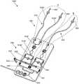
图10示出了包括图9所示实施例的一次性泵模块的一次性泵模块组件的透视图;Figure 10 shows a perspective view of a disposable pump module assembly including the disposable pump module of the embodiment shown in Figure 9;
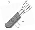
图11和图12分别示出了本公开的一次性泵模块和一次性泵模块组件的另一实施例的透视图,其中设想两个不同的流体回路路径;Figures 11 and 12 show perspective views of another embodiment of a disposable pump module and disposable pump module assembly of the present disclosure, respectively, wherein two different fluid circuit paths are envisaged;
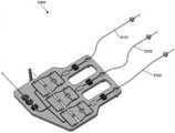
图13和图14示出了本公开的一次性泵模块组件的另一实施例的透视图,其中设想三个不同的流体回路路径;13 and 14 illustrate perspective views of another embodiment of the disposable pump module assembly of the present disclosure, wherein three different fluid circuit paths are envisaged;
图15示出了图12和图13所示的一次性泵模块组件实施例的替代方案的透视图,以及Figure 15 shows a perspective view of an alternative to the disposable pump module assembly embodiment shown in Figures 12 and 13, and
图16和图17示出了根据本公开的模块化流体输送系统的示意图。16 and 17 show schematic diagrams of a modular fluid delivery system according to the present disclosure.
具体实施方式Detailed ways
参考图1,示出了根据本公开的实施例的流体输送系统100的示意图。流体输送系统100用于输送包含在供应站10中的流体,所述流体基于其中实施流体输送系统的特定技术领域而具有不同的性质。Referring to FIG. 1 , a schematic diagram of a
例如,在流体输送系统100是用于医疗领域的注入系统的情况下,包含在供应站10中并且将被注入到患者血管系统中的流体可以是在患者的扫描检查期间(例如在CT、MRI或超声检查期间)为了增强患者体内的目标(身体)特征(例如人体结构或器官)的对比度而施用的造影剂。特别地,在成像应用中(其中以无创方式产生患者体内的视觉表示而无需借助手术技术),造影剂的使用使目标特征更明显。结果,有利地突出原本难以与其他附近特征(例如,周围组织)区分的目标特征。这极大地方便了临床医生在诊断应用中的任务,特别是病变的识别和/或表征、其演变的监测或对医学治疗的反应。例如,在CT应用中,造影剂可以是基于碘的造影剂,包括泛影酸盐、碘沙酸盐、碘帕醇、碘海醇、碘克西兰、碘普罗胺或碘克沙醇。包括碘帕醇的商业造影剂的示例是由Bracco Diagnostics

根据本公开的实施例,流体输送系统100配置用于以连续注入/输注模式和/或作为单次剂量来输送超声造影剂(USCA)。特别地,流体输送系统100用于输送液体组合物,所述液体组合物包括均匀分布在液体载体(优选为水性液体载体)中的微粒悬浮液,所述微粒包含截留的纯气体或气体混合物,所述气体混合物包括至少一种生理学上可接受的卤化气体。该卤化气体优选地选自CF4、C2F6、C3F8、C4F8、C4F10、C5F12、C6F14或SF6。气体混合物还可以包含气体,例如空气、氧气、氮气、氦气、氙气或二氧化碳。在多种情况下,所述微粒(微泡或微球)包含氮气或空气与至少一种全氟化气体的混合物,其比例可以在1至99%之间变化。用于对比增强超声(CEUS)应用中的商业造影剂的示例是由

仍然参考医学领域,包含在供应站10中并且将被注入到患者的血管系统中的流体也可以是包含生理或等渗溶液(例如氯化钠)的盐水溶液。替代地,所述流体可以是液体药剂或药物。Still referring to the medical field, the fluid contained in the
如上所述,本公开的输送系统100可以用于在许多技术领域中输送流体,不一定与医学/诊断领域相关。例如,包含在供应站10中的流体可以是胶水制剂、油漆制剂、涂料制剂或要求适当达到/控制其输送特性(例如温度)的物质/制剂。As noted above, the
流体输送系统100包括加压单元20,所述加压单元作用于流体,使得它将以基于与特定的输送用途相关的要求预先设置的预定压力和流速离开流体输送系统(并因此将输送它)。详细地,加压单元20包括泵模块30和驱动单元M,所述驱动单元与泵模块关联以用于其操作。泵模块30包括室31,活塞32在所述室内通过驱动单元M往复运动(即来回移动-参见双箭头A)。根据图中所示的实施例,室31表示为圆柱形筒(例如,类似于注射器筒);然而,也可以设想适用于该目的的其他不同构造。活塞32包括活塞杆33和柱塞34,柱塞布置成大致垂直于活塞杆并且具有大致对应于室径向延伸(即室宽度)的径向延伸。因此,与室31的内壁协作,柱塞34在柱塞的一侧(在图1的实施例中在柱塞的左侧)限定第一子室35,并且在柱塞的相对侧(在图1的实施例中在柱塞的右侧)限定第二子室36。在流体输送系统的操作期间,活塞32来回移动(参见双箭头A),因此所述第一和第二子室35、36的总容积连续交替地变化,因此这些子室是可变容积子室。例如,当活塞32在图1中向右移动时,第一子室35的容积增加而第二子室36的容积减小;相反,当活塞32在图1中向左移动时,第二子室36的容积增加而第一子室35的容积减小。根据图1所示的实施例,柱塞34设置在活塞杆33的轴向端部(即,与连接到驱动单元M的轴向端部相对的轴向端部)处。替代地,柱塞34可以设置在沿着活塞杆33的纵向延伸的不同位置处(图中未示出实施例),条件是室31的两个底壁31a、31b允许活塞杆33通过其中的密封轴向运动。The
本公开的流体输送系统100还包括与供应站10和泵模块30流体连通的入口流体回路40。入口流体回路40包括将(包含在供应站10中的)流体供应到第一可变容积子室35和第二可变容积子室36的流体路径,使得室31填充有待输送的合适的流体体积量(箭头B)。The
详细地,入口流体回路40包括与供应站10流体连通的第一入口流体路径41,所述第一入口流体路径41包括允许流体从供应站10排出的供应站阀11。供应站阀11是由流体输送系统操作的主动阀,其将在本说明书的下文中详细解释。In detail, the
在供应站阀11的下游,入口流体回路40分支成分别与第一子室35和第二子室36流体连通的第二入口流体路径42和第三入口流体路径43。第一子室35设置有第一入口44,所述第一入口允许第二入口流体路径42与第一子室35流体连通。类似地,第二子室36设置有第二入口46,所述第二入口允许第三入口流体路径43与第二子室36流体连通。Downstream of the
在第一入口端口44的上游,第二入口流体路径42设置有第一入口流体回路阀45,所述第一入口流体回路阀允许流体通过第二入口流体路径42流入第一子室35。根据本公开的实施例,第一入口流体回路阀45是止回阀,即单向阀,其允许流体仅在一个方向上流过它,具体地是从供应站10流向第一子室35,由此避免流体向供应站10回流。Upstream of the
类似地,在第二入口端口46的上游,第三入口流体路径43设置有第二入口流体回路阀47,所述第二入口流体回路阀允许流体通过第三入口流体路径43流入第二子室36。根据本公开的实施例,第二入口流体回路阀47是止回阀,即单向阀,其防止反向流动,允许流体仅在一个方向上流过它,具体地是从供应站10流向第二子室36,由此避免流体向供应站10回流。Similarly, upstream of the
优选地,第一和第二入口流体回路阀45、47是球形止回阀,其中在主体阀内部存在用于调节流体流量的球。Preferably, the first and second inlet
流体输送系统100还包括与入口流体回路40分离的出口流体回路50。出口流体回路50与泵模块30流体连通,并且它包括允许流体输送系统100将流体从室31排出并将其输送到流体输送系统外部(参见箭头B)的第一出口流体路径51和第二出口流体路径52。详细地,第一子室35设置有第一出口端口53,所述第一出口端口允许第一出口流体路径51与第一子室35流体连通。类似地,第二子室36设置有第二出口端口54,所述第二出口端口允许第二出口流体路径52与第二子室36流体连通。正如将在本公开的下文中详细描述的那样,在操作中,出口流体回路50的第一和第二出口流体路径51、52交替地从第一子室35和第二子室36排出流体。The
在第一出口端口53的下游,第一出口流体路径51设置有第一出口流体回路阀55,所述第一出口流体回路阀允许流体通过第一出口流体路径51从第一子室35排出。根据本公开的实施例,第一出口流体回路阀55是止回阀,即单向阀,其防止反向流动,允许流体仅在一个方向上流过它,具体地是从第一子室35离开,由此避免流体流回到所述第一子室35中。Downstream of the
类似地,在第二出口端口54的下游,第二出口流体路径52设置有第二出口流体回路阀56,所述第二出口流体回路阀允许流体通过第二出口流体路径52从第二子室36排出。根据本公开的实施例,第二出口流体回路阀56是止回阀,即单向阀,其允许流体仅在一个方向上流过它,具体地是从第二子室36离开,由此避免流体流回到所述第二子室36中。Similarly, downstream of the
优选地,第一和第二出口流体回路阀55、56是弹簧加载的止回阀,其中弹簧部件用于通过消除重力对止回阀功能的影响来支持阀操作。更优选地,第一和第二出口流体回路阀55、56是弹簧加载的球形止回阀。Preferably, the first and second outlet
根据本公开,流体输送系统100还包括流体地连接所述第一和第二可变容积子室35、36的再循环流体回路60,所述再循环流体回路60与致动器70协作,用于在所述第一和第二可变容积子室35、36之间沿两个方向管理流体通道。再循环流体回路60是附加流体回路,即允许第一和第二可变容积子室35、36之间的直接流体连通的另一流体路径。因此,在本说明书中,术语再循环流体回路或附加流体回路或再循环流体路径彼此等同并且意在指示流体输送系统的相同部件。In accordance with the present disclosure, the
根据图1所示的实施例,再循环流体回路60在室31的外部,并且它在子室35、36的入口端口的上游和入口流体回路阀45、47的下游流体地连接入口流体回路40的单独分支。详细地,再循环流体回路路径60的第一轴向端部61在第一入口流体回路阀45的下游与入口流体回路40的第二入口流体路径42流体地连接。类似地,再循环流体回路60的第二轴向端部62在第二入口流体回路阀47的下游与入口流体回路40的第三入口流体路径43流体地连接。According to the embodiment shown in FIG. 1 , the
致动器70是由流体输送系统操作的主动阀,其将在本说明书的下文中详细解释。优选地,致动器70是由流体输送系统100的处理器P自动控制和操作的机电驱动阀。如图中示意性所示,处理器P控制和操作致动器70、驱动单元M和供应站阀11。换言之,处理器P是控制单元,其根据操作者选择的预定输送(注入)协议来控制和致动流体输送系统的一些部件。The
下面参考图2-图4描述根据本公开的第一实施例(在图1中示出)的输送系统的操作。The operation of the delivery system according to the first embodiment of the present disclosure (shown in FIG. 1 ) is described below with reference to FIGS. 2-4 .
供应站10包含必须由输送系统100输送(箭头B)的流体(未示出)。
作为第一启动步骤,根据本公开的流体输送方法包括用待输送的流体填充第一和第二子室35、36的步骤。为了执行所述填充步骤,处理器P打开供应站阀11,它关闭再循环流体回路60的致动器70并且它作用于驱动单元M以在室31内移动活塞32,由此允许流体离开供应站10并流动通过入口流体回路40。详细地,一旦活塞32沿着第一方向(例如图2的箭头C)轴向平移,在由于活塞轴向运动而增加其容积的第一子室(例如子室35)中生成欠压,并且流体流动通过入口流体回路40的第一入口流体路径41和第二入口流体路径42,通过相应的第一入口流体回路阀(例如第一入口流体回路阀45),然后它进入并填充所述第一子室。同时,由于活塞轴向运动而减小其容积的第二子室(例如子室36)内包含的空气通过相对的第二入口流体回路阀(例如第二入口流体回路阀47)所具有的排气装置从输送系统引出。接着,为了填充第二子室并引动第一子室,处理器P作用于驱动单元M以反转活塞运动,使得活塞沿着与第一方向相反的第二方向(例如图3的箭头D)轴向平移。由于致动器70在活塞移动时保持关闭,因此在由于活塞轴向运动而增加其容积的第二子室(例如子室36)中生成欠压,并且流体流动通过入口流体回路40的第一入口流体路径41,通过相应的第二入口流体回路阀(例如第二入口流体回路阀47),然后它进入并填充所述第二子室。同时,由于活塞轴向运动而减少其容积的第一子室(例如子室35)内仍然包含的空气通过相应的第一入口流体回路阀(例如第一入口流体回路阀45)所具有的排气装置从输送系统引出。在引动步骤期间,一些流体离开输送系统,使得也执行出口流体回路50的引动。As a first start-up step, the fluid delivery method according to the present disclosure includes the step of filling the first and
替代地,流体输送系统的空气引动由与流体回路阀分开的专用排气装置(图中未示出)执行。根据替代实施例,专用排气装置与流体输送系统的每个阀关联。根据另一实施例,流体输送系统仅具有一个专用排气装置。优选地,所述仅一个专用排气装置与再循环流体路径的致动器关联。Alternatively, air priming of the fluid delivery system is performed by a dedicated exhaust (not shown) separate from the fluid circuit valve. According to an alternative embodiment, a dedicated exhaust is associated with each valve of the fluid delivery system. According to another embodiment, the fluid delivery system has only one dedicated exhaust. Preferably, the only one dedicated exhaust is associated with the actuator of the recirculation fluid path.
一旦室31充满流体并且输送系统的引动完成,处理器P关闭供应站阀11并打开再循环流体回路60的致动器70,同时驱动单元M仍然被激活并保持活塞32在室31内轴向平移。Once the
替代地,处理器P打开再循环流体回路60的致动器70,同时仍保持供应站阀11打开。Instead, the processor P opens the
当活塞32朝向室31的底壁31a移动时(参见图2的箭头C),柱塞34的平移导致第一子室35的容积增加和第二子室36的相应容积减小。此外,由于致动器70在程序的该阶段处于打开状态,因此最初包含在第二子室36内的流体被柱塞34推出室31,通过第二入口端口46,然后通过流入再循环流体回路60,并且通过打开的致动器70,它通过进入第一入口44而进入第一子室35。As the
必须指出的是,包含在第二子室36内并被柱塞34推送的流体既不允许流回供应站10,也不允许进入出口流体回路50的第二流体路径52。实际上,供应站阀11被关闭并且第一和第二入口流体回路阀45、47都是单向阀,其允许流体从供应站10流入室31,但反之不行,由此避免从子室36排出的流体通过入口流体回路40的第一和第二入口流体路径41、42流回。此外,由于第二出口流体回路阀56仅在从第二子室36排出的流体具有足够高的压力以克服所述阀的内部弹性时才自动打开(优选地,第二出口流体回路阀56是弹簧加载的球形止回阀),当致动器70处于打开状态时,从第二子室36排出的流体不具有足够的力来克服第二出口流体回路阀56的内部弹性,因此流体不会被输送到流体输送系统100的外部,相反地,从第二子室36排出的流体重新填充第一子室35。It must be noted that the fluid contained within the
一旦活塞32已到达其第一端止挡,即柱塞34已完成其在第一方向(图2中的右方向--参见箭头C)上的轴向平移,并且它到达室31的底壁31a附近,使得第二子室36包含相当小体积的流体,而第一子室35包含大体积的流体,处理器P就作用于驱动单元M以反转活塞轴向平移(图3中的左方向--参见箭头D)。在室31内的活塞32的反向运动期间,上述相同的操作条件仍然适用,即致动器70保持在其打开状态,而供应站阀11保持在其关闭状态。Once the
柱塞在相反方向上的轴向平移导致第二子室36的容积增加和第一子室35的相应容积减小。由于致动器70处于其打开状态,最初包含在第一子室35内的流体被柱塞34推出室31,通过第一入口端口44,然后流入再循环流体回路60并通过打开的致动器70,它通过第二入口46进入第二子室36。Axial translation of the plunger in the opposite direction results in an increase in the volume of the
上面参考在第一方向(图2的右方向--参见箭头C)上的活塞平移提供的考虑仍然适用于在与第一方向相反的第二方向(图3的左方向--参见箭头D)上的活塞平移。因此,包含在第一子室35内并被柱塞34推送的流体既不允许流回供应站10,也不允许进入出口流体回路50的第一出口流体路径51。实际上,供应站阀11被关闭并且第一和第二入口流体回路阀45、47都是单向阀,其允许流体从供应站10流入室31,但反之不行,由此避免从第一子室35排出的流体通过入口流体回路40的第一和第二入口流体路径41、42流回。此外,由于第一出口流体回路阀55仅在从第一子室35排出的流体具有足够高的压力以克服所述阀的内部弹性时才自动打开(优选地,第一出口流体回路阀55是弹簧加载的球形止回阀),当致动器70处于打开状态时,从第一子室35排出的流体不具有足够的力来克服第一出口流体回路阀55的内部弹性,因此流体不会被输送到流体输送系统100的外部,相反地,从第一子室35排出的流体重新填充第二子室36。The considerations provided above with reference to piston translation in the first direction (right direction in Figure 2 - see arrow C) still apply in the second direction opposite the first direction (left direction in Figure 3 - see arrow D) on the piston translation. Therefore, the fluid contained within the
一旦活塞32已到达其第二端止挡,即柱塞34已完成其在第二方向(图3中的左方向--参见箭头D)上的轴向平移,并且它到达室31的底壁31b附近,使得第一子室35包含相当小体积的流体,而第二子室36包含大体积的流体,处理器P作用于驱动单元M以再次反转活塞轴向平移(图4中的右方向--参见箭头C),由此开始流体输送系统100的室31的新充装/排出循环。当然,可以布置任何数量的循环,所述数量取决于待输送的特定流体的要求和实施输送系统的特定应用的要求。Once the
从以上显而易见的是,本公开的流体输送系统允许流体在离开流体输送系统之前进行连续和预定的运动(例如,在容积、活塞平移速度方面)。如上文已经提到的,在开始输送流体之前要求实现和/或保持特定流体性质(例如,组合物均匀性、温度、粘度、混合物、流动性)的情况下,本公开的该方面是特别有利的。实际上,根据本公开的流体输送系统允许引入室31中的流体在流体输送系统100不输送时,即流体不明确地离开流体输送系统时通过在第一和第二子室35、36之间交替充装/排出而连续再循环。由于再循环流体回路60和与其关联的致动器70,流体的再循环及其在两个子室之间的再分配有助于平衡其中的压力。该方面是特别有利的,原因是它至少在初始阶段当输送系统尚未将流体输送到系统之外时允许在有限的(低)压力下操作系统,由此限制了如果系统需要在更高的压力值下操作可能需要实施的技术约束。As apparent from the above, the fluid delivery systems of the present disclosure allow for continuous and predetermined motion (eg, in terms of volume, piston translation velocity) of the fluid prior to exiting the fluid delivery system. As already mentioned above, this aspect of the present disclosure is particularly advantageous where it is required to achieve and/or maintain certain fluid properties (eg, composition uniformity, temperature, viscosity, mixture, fluidity) prior to initiating delivery of the fluid of. In fact, the fluid delivery system according to the present disclosure allows fluid introduced into the
此外,根据本公开的输送方法包括开始输送包含在室31内的流体(即输送到流体输送系统的外部)的步骤。为了执行所述步骤,处理器P关闭再循环流体回路60的致动器70,并且它打开供应站阀11。因此,在输送流体期间(流体离开输送系统--参见箭头B),供应站阀11保持在其打开状态,原因是用新流体重新填充子室很重要,以便避免流体扰动可能影响活塞的正确功能以及因此影响整个输送系统的正确功能。由于关闭致动器70防止任何流体流动通过再循环流体回路60(同时,如上面已经所述,第一和第二入口流体回路阀45、47不允许流体向供应站10的任何回流),在第一方向(箭头C)上和在第二相反方向(箭头D)上推动柱塞34允许流体相应地离开第二出口端口54和第一出口端口53。因此,当流体被推送通过第二出口端口54(箭头C)时,流体流入出口流体回路50的第二出口流体路径52,然后它通过第二出口流体回路阀56,原因是在程序的该阶段,由于致动器70关闭,因此流体压力足够高以克服所述第二出口流体回路阀56的内部弹性。类似地,当流体被推送通过第一出口端口53(箭头D)时,流体流入出口流体回路50的第一出口流体路径51,然后它通过第一出口流体回路阀55,原因是在程序的该阶段,由于致动器70关闭,流体压力足够高以克服所述第一出口流体回路阀55的内部弹性。因此,流体最终通过其从第一和第二子室35、36依次排出而被输送(箭头B)。实际上,由于第一和第二出口流体回路阀55、56是单向阀,流体不能通过欠压路径回流,因此它被强制输送(箭头B)。Furthermore, the delivery method according to the present disclosure includes the step of initiating delivery of the fluid contained within the chamber 31 (ie, to the outside of the fluid delivery system). To perform said steps, the processor P closes the
如上所述,在输送流体的步骤(箭头B)期间,供应站阀11保持打开,使得新流体可以交替进入两个子室,并且当活塞在室31内轴向平移时不会发生不希望的扰动效应。即使在输送步骤期间进入系统的新流体尚未通过致动器70和再循环流体回路60,也应当注意新流体不会立即输送。实际上,新流体进入处于欠压的子室,而系统输送的流体是包含在加压子室中的流体。因此,在被输送之前,由于活塞轴向平移,新流体在相应子室内持久地移动和混合,由此确保在最终离开系统之前达到期望的输送条件。As mentioned above, during the step of delivering fluid (arrow B), the
如上文已经提到的那样,申请人已经发现,通过让流体流动通过再循环流体回路60和与其关联的致动器70,室31内的流体的再循环可以显著降低或甚至完全消除流体在被输送时,尤其是在液体输送程序开始时压力脉动的风险。实际上,由于再循环流体回路60和致动器70的存在,根据本公开的流体输送系统可以适当地控制在活塞32开始移动时发生的压力下降或压力峰值。实际上,根据本公开,当室31内的流体的再循环已经开始时,流体输送系统开始输送流体(在流体输送系统的外部),因此当活塞已经在室31内部移动时输送将开始。这显然意味着流体输送的开始与活塞移动的开始并非同时,原因是当活塞已经在室31内轴向平移以允许执行所述流体再循环时才开始流体的输送。As already mentioned above, applicants have found that by flowing fluid through the
此外,如上文已经提到的,申请人还发现,通过让流体流动通过再循环流体回路60和与其关联的致动器70,室31内的流体的再循环可以显著减少或甚至完全消除流体输送系统的延迟时间。延迟时间是流体输送系统为了准备好输送流体而不可避免地需要的技术时间。实际上,一旦处理器P指示将电流输送到驱动单元M,典型地,所述电流建立作用在转子磁体上的电磁场,所述转子磁体在齿轮上产生扭矩,从而导致活塞开始其运动。当活塞开始移动时,流体压力开始增加,并且它仍然需要一些额外的时间才能达到并超过为第一和第二出口流体回路阀55、56设置的压力阈值。所有这些时间的总和称为“延迟时间”,并且它远不能忽略不计,从而不可避免地导致流体输送到流体输送系统之外的延迟。由于再循环流体回路60和与其关联的致动器70的存在,本公开的流体输送系统100可以克服或减少所述延迟时间,原因是为了在室31内执行流体再循环,活塞32在流体输送之前开始很好地移动。因此,一旦处理器P关闭致动器70以开始输送流体(箭头B),流体压力立即增加并很快超过为第一和第二出口流体回路阀55、56设置的压力阈值。因此,在处理器P下令开始输送之后,系统很快就会输送流体。Furthermore, as already mentioned above, Applicants have also discovered that by flowing the fluid through the
参考图5,示出了根据本公开的替代实施例的另一流体输送系统200的示意图,其中两个泵模块230、230'并联布置。流体输送系统200用于输送包含在第一供应站210中的第一流体和包含在第二供应站210'中的第二流体,其中所述第一流体和所述第二流体彼此不同。Referring to Figure 5, a schematic diagram of another
在流体输送系统200是用于医疗领域的注入系统的情况下,包含在第一供应站210中并且将被注入到患者的血管系统中的第一流体可以是例如造影剂,而包含在在第二供应站210'中的第二流体可以是包括生理或等渗溶液(例如氯化钠)的盐水溶液。替代地,所述第一流体和/或所述第二流体可以是液体药剂或药物。Where the
如上文已经提到的,本公开的流体输送系统200可以用于在许多技术领域中输送流体,不一定与医学/诊断领域严格相关。例如,分别包含在第一和第二供应站210、210'中的第一流体和第二流体可以是胶水制剂、油漆制剂、涂料制剂或要求适当达到/控制其输送特性(例如温度)的物质/制剂中的两种或更多种组分。As already mentioned above, the
流体输送系统200包括加压单元220,所述加压单元作用于第一流体和第二流体,使得它们交替地输送到流体输送系统的外部(以由操作者或由流体输送系统控制单元基于为特定输送用途设计的要求预先设置的预定压力和流速)并在流体输送系统内再循环,如将在本说明书的下文中详细公开。加压单元220包括第一泵模块230、第二泵模块230'以及与两个泵模块关联以用于其操作/致动的驱动单元M。每个泵模块230、230'分别包括室231、231',活塞232、232'在所述室内通过驱动单元M往复运动(即来回移动--参见双箭头E、E')。根据图中所示的实施例,室231、231'表示为圆柱形筒(例如,类似于注射器筒);然而,也可以设想适用于该目的的其他不同构造。每个活塞232、232'分别包括活塞杆233、233'和柱塞234、234',柱塞布置成大致垂直于活塞杆并且具有大致对应于室径向延伸(即室宽度)的径向延伸。因此,与所述室231、231'的内壁协作,每个柱塞234、234'在柱塞的一侧(在图5的实施例中在柱塞的左侧)限定相应的第一子室235、235',并且在柱塞的相对侧(在图5的实施例中在柱塞的右侧)限定相应的第二子室236、236'。在流体输送系统200的操作期间,活塞232、232'来回移动(参见双箭头E、E'),因此所述第一子室235、235'和第二子室236、236'的总体积连续交替地变化,这些子室是可变容积子室。例如,当活塞232、232'在图5中向右移动时,第一子室235、235'的容积增加而第二子室236、236'的容积减小;相反,当活塞232、232'在图5中向左移动时,第二子室236、236'的容积增加而第一子室235、235'的容积减小。根据图5所示的实施例,柱塞234、234'设置在活塞杆233、233'的轴向端部(即,与连接到驱动单元M的轴向端部相对的轴向端部)处。替代地,柱塞234、234'可以设置在沿着活塞杆233、233'的纵向延伸的不同位置处(图中未示出的实施例),条件是室231的底壁231a、231b以及室231'的底壁231a'、231b'允许活塞杆233、233'通过其中(即通过所述室)的密封轴向运动。The
本公开的流体输送系统200还包括第一入口流体回路240和第二入口流体回路240'。详细地,第一入口流体回路240与第一供应站210和与第一泵模块230流体连通,并且类似地,第二入口流体回路240'与第二供应站210'和与第二泵模块230'流体连通。第一入口流体回路240包括将第一流体(包含在第一供应站210中)供应到第一可变容积子室235和第二可变容积子室236的入口流体路径,使得室231填充有待输送到流体输送系统200外部的合适体积量的第一流体(箭头F)。类似地,第二入口流体回路240'包括将第二流体(包含在第二供应站210'中)供应到第一可变容积子室235'和第二可变容积子室236'的入口流体路径,使得室231'填充有待输送到流体输送系统200外部的合适体积量的第二流体(箭头F')。The
详细地,第一和第二入口流体回路240、240'包括与供应站210、210'流体连通的第一入口流体路径241、241',所述第一入口流体路径241、241'包括允许相应的流体从供应站210、210'排出的供应站阀211、211'。供应站阀211、211'是由流体输送系统操作的主动阀,正如将在本说明书的下文中详细解释的那样。In detail, the first and second
在供应站阀211、211'的下游,第一和第二入口流体回路240、240'分支成分别与第一子室235、235'和第二子室236、236'流体连通的第二入口流体路径242、242'和第三入口流体路径243、243'。第一子室235、235'设置有允许第二入口流体路径242、242'与第一子室235、235'流体连通的第一入口端口244、244'。类似地,第二子室236、236'设置有允许第三入口流体路径243、243'与第二子室236、236'流体连通的第二入口端口246、246'。Downstream of the
在第一入口端口244、244'的上游,第二入口流体路径242、242'设置有第一入口流体回路阀245、245',所述第一入口流体回路阀允许相应的流体(即,从第一供应站210离开的第一流体和从第二供应站210'离开的第二流体)通过第二入口流体路径242、242'流入第一子室235、235'。根据本公开的实施例,第一入口流体回路阀245、245'是止回阀,即单向阀,其允许流体仅在一个方向上流过它,具体地是从供应站210、210'流向第一子室235、235',并且避免流体向供应站210、210'回流。Upstream of the
类似地,在第二入口端口246、246'的上游,第三入口流体路径243、243'设置有第二入口流体回路阀247、247',所述第二入口流体回路阀允许相应的流体(即,从第一供应站210离开的第一流体和从第二供应站210'离开的第二流体)通过第三入口流体路径243、243'流入第二子室236、236'。根据本公开的实施例,第二入口流体回路阀247、247'是止回阀,即单向阀,其防止反向流动,从而允许流体仅在一个方向上流过它,具体地是从供应供应站210、210'流向第二子室236、236',并且避免流体向供应站210、210'回流。Similarly, upstream of the
优选地,第一入口流体回路阀245、245'和第二入口流体回路阀247、247'是球形止回阀,其中在主体阀内部存在用于调节流体流量的球。Preferably, the first inlet
本公开的流体输送系统200还包括第一出口流体回路250(其与第一入口流体回路240分离)和第二出口流体回路250'(其与第二入口流体回路240'分离)。详细地,第一出口流体回路250与第一泵模块230流体连通,并且类似地,第二出口流体回路250'与第二泵模块230'流体连通。第一和第二出口流体回路250、250'都包括分别允许流体输送系统200从室231排出第一流体(参见箭头F)和从室231'排出第二流体(参见箭头F')的第一出口流体路径251、251'和第二出口流体路径252、252'。详细地,第一子室235、235'设置有允许第一出口流体路径251、251'与所述第一子室235、235'流体连通的第一出口端口253、253'。类似地,第二子室236、236'设置有允许第二出口流体路径252、252'与所述第二子室236、236'流体连通的第二出口端口254、254'。如将在本公开的下文中详细描述,在操作中,出口流体回路250、250'的第一出口流体路径251、251'和第二出口流体路径252、252'交替地从第一子室235和从第二子室236排出第一流体以及从第一子室235'和第二子室236'排出第二流体。The
在第一出口端口253、253'的下游,第一出口流体路径251、251'设置有第一出口流体回路阀255、255',所述第一出口流体回路阀允许第一和第二流体分别通过第一出口流体路径251、251'从第一子室235、235'和通过第二出口流体路径252、252'从第二子室236、236'排出。根据本公开的实施例,第一出口流体回路阀255、255'是止回阀,即单向阀,其防止反向流动,从而允许流体仅在一个方向上流过它,具体地是从第一子室235、235'离开,并且避免流体流回所述第一子室235、235'。Downstream of the
类似地,在第二出口端口254、254'的下游,第二出口流体路径252、252'设置有第二出口流体回路阀256、256',所述第二出口流体回路阀允许第一和第二流体分别通过第二出口流体路径252、252'从第二子室236、236'排出。根据本公开的实施例,第二出口流体回路阀256、256'是止回阀,即单向阀,其允许流体仅在一个方向上流过它,具体地从第二子室236、236'离开,从而避免流体流回所述第二子室236、236'。Similarly, downstream of the
优选地,第一出口流体回路阀255、255'和第二出口流体回路阀256、256'是弹簧加载的止回阀,其中弹簧部件用于通过消除重力对止回阀功能的影响来支持阀操作。更优选地,第一出口流体回路阀255、255'和第二出口流体回路阀256、256'是弹簧加载的球形止回阀。Preferably, the first outlet
根据图5所示的实施例,本公开的流体输送系统200还包括第一再循环流体回路260和第二再循环流体回路260',所述再循环流体回路在本说明书中也称为附加流体回路(即相对于上述入口和出口流体回路的附加流体回路)。详细地,第一再循环流体回路260流体地连接第一泵模块230的室231的第一和第二可变容积子室235、236,所述第一再循环流体回路260与第一致动器270(由所述第一再循环流体回路260拥有)协作,用于在所述第一和第二可变容积子室235、236之间沿两个方向管理第一流体的通道。类似地,第二再循环流体回路260'流体地连接第二泵模块230'的室231'的第一和第二可变容积子室235'、236',所述第二再循环流体回路260'与第二致动器270'(由所述第二再循环流体回路260'拥有)协作,用于在所述第一和第二可变容积子室235'、236'之间沿两个方向管理第二流体的通道。According to the embodiment shown in FIG. 5 , the
根据图5所示的实施例,第一和第二再循环流体回路260、260'在室231、231'的外部并且它们分别在相应子室235、235'和236、236'的入口端口244、244'和246、246'的上游流体地连接第一和第二入口流体回路240、240'的独立分支。详细地,关于第一泵模块230,第一再循环流体回路260的第一轴向端部261在其第一入口流体回路阀245的下游与第一入口流体回路240的第二入口流体路径242流体地连接,而第一再循环流体路径260的第二轴向端部262在其第二入口流体回路阀247的下游与第一入口流体回路240的第三入口流体路径243流体地连接。类似地,关于第二泵模块230',第二再循环流体回路260'的第一轴向端部261'在其第一入口流体回路阀245'的下游与第二入口流体回路240'的第二入口流体路径242'流体地连接,而第二再循环流体回路260'的第二轴向端部262'在其第二入口流体回路阀247'的下游与第二入口流体回路240'的第三入口流体路径243'流体连接。According to the embodiment shown in Figure 5, the first and second
第一和第二致动器270、270'是由流体输送系统200操作的主动阀,其将在本说明书的下文中详细解释。优选地,第一和第二致动器270、270'是由流体输送系统200的处理器或控制单元P自动控制和操作的机电驱动阀。如图中示意性所示,处理器P控制和操作第一和第二致动器270、270'、驱动单元M以及第一和第二供应站阀211、211'。The first and
根据图6所示的替代实施例,示意性地表示流体输送系统200',其中所述两个泵模块230、230'串联布置,而不是如图5的实施例中所示并联布置。在该替代实施例中,两个室231、231'分离并且彼此间隔开,而具有两个间隔开的柱塞234、234'的公共活塞杆233设置到所述室231、231',从而限定相应的第一可变容积子室235、235'和第二可变容积子室236、236'。所述替代实施例的所有其余部件(以及其功能)与图5中所示的流体输送系统200的相应部件相同,因此用相同的附图标记表示。According to an alternative embodiment shown in FIG. 6 , a
下面将参考与医学领域,更具体地与为了诊断目的交替或同时注入造影剂和盐水溶液相关的应用来说明根据本公开的图6中所示的所述替代流体输送系统的操作。然而,如在本说明书中上面已经提到的那样,根据本公开的流体输送系统可以用于与医疗/保健应用不相关的其他技术领域。此外,将在下文参考本公开的输送系统的一些实施例说明的一般操作原理适用于本说明书中公开的和/或与其相关的附图中所示的多个实施例。The operation of the alternative fluid delivery system shown in FIG. 6 according to the present disclosure will be described below with reference to applications related to the medical field, and more particularly to the alternating or simultaneous injection of contrast media and saline solution for diagnostic purposes. However, as already mentioned above in this specification, the fluid delivery system according to the present disclosure may be used in other technical fields not related to medical/healthcare applications. Furthermore, the general principles of operation, which will be described below with reference to some embodiments of the delivery system of the present disclosure, apply to the various embodiments disclosed in this specification and/or shown in the drawings associated therewith.
作为根据本公开的所述替代流体输送系统的操作方法的示例,参考图7和图8,其中以根据图6所示实施例的流体输送系统200'为例。As an example of a method of operation of the alternative fluid delivery system according to the present disclosure, reference is made to FIGS. 7 and 8 , in which a
供应站210包含要求注入到患者(参见箭头F)的第一流体(未示出),例如造影剂,而供应站210'包含要求由所述输送系统200'注入到患者(参见箭头F')的第二流体(未示出),例如盐水溶液。典型地,在F处离开的第一流体和在F'处离开的第二流体通过公共管道(患者管线--未示出)输送到患者,所述管道机械地和流体地连接到用于进入患者脉管系统的导管和/或针头。
作为第一启动步骤,根据本公开的输送方法包括用第一流体填充第一泵模块230的第一和第二子室235、236的步骤,以及类似地,用第二流体填充第二泵模块230'的第一和第二子室235'、236'的步骤。为了执行所述填充步骤,处理器P打开供应站阀211、211',它关闭第一和第二再循环流体回路260、260'的致动器270、270',并且它作用于驱动单元M以使公共活塞232在室231、231'内往复运动,由此允许第一和第二流体分别离开供应站210、210',并且流动通过第一入口流体回路240和通过第二入口流体回路240'。详细地,一旦活塞232沿着第一方向(例如图7的箭头G)轴向平移,在由于活塞轴向运动而增加其容积的第一子室(例如子室235、235')中生成欠压。因此,允许相应的流体流动通过第一和第二入口流体回路240、240'的第一入口流体路径241、241'和第二入口流体路径242、242',通过对应的第一入口流体回路阀(例如,第一入口流体回路阀245、245'),然后它们进入并填充所述第一子室。同时,由于活塞轴向运动(箭头G)而减小其容积的第二子室(例如子室236、236')中包含的空气通过相对的第二入口流体回路阀(例如,第二入口流体回路阀247、247')所具有的排气装置从流体输送系统引出。事实上,所述第一子室235、235'中包含的空气通常经由通过第一入口端口244、244',然后通过第二入口流体路径242、242',最后通过所述第一入口流体回路阀245、245'而被强制离开所述子室。随后,为了用相应的流体填充第二子室并引动第一子室(即从其排出空气),处理器P作用于驱动单元M以反转活塞运动,使得活塞沿着与第一方向相反的第二方向(例如图8的箭头H)轴向平移。由于在填充和引动步骤期间在活塞移动时致动器270、270'保持关闭,因此在由于活塞轴向运动(箭头H)而增加其容积的第二子室(例如子室236、236')中生成欠压。因此,允许第一和第二流体相应地流动通过第一和第二入口流体回路240、240'的第一入口流体路径241、241'和第三入口流体路径243、243',通过对应的第二入口流体回路阀(例如第二入口流体回路阀247、247'),然后它们进入并填充所述第二子室。同时,由于活塞轴向运动(箭头H)而减小其容积的第一子室(例如,子室235、235')中仍然包含的空气通过对应的第一入口流体回路阀(例如第一入口流体回路阀245、245')所具有的排气装置从流体输送系统引出。事实上,所述第二子室236、236'中包含的空气通常经由通过第二入口端口246、246',然后通过第三入口流体路径243、243',最后通过第二入口流体回路阀247、247'而被强制离开所述子室。在引动步骤期间,一定量的第一流体和第二流体通过第一出口流体回路250和第二出口流体回路250'离开流体输送系统,使得也可以适当地执行所述第一出口流体回路250和第二出口流体回路250'的引动。As a first start-up step, the delivery method according to the present disclosure includes the steps of filling the first and
替代地,流体输送系统的空气引动由与流体回路阀分开的专用排气装置(图中未示出)执行。根据替代实施例,专用排气装置与流体输送系统的每个阀关联。根据另一替代实施例,专用排气装置与第一和第二再循环流体回路260、260'的每个致动器270、270'关联。Alternatively, air priming of the fluid delivery system is performed by a dedicated exhaust (not shown) separate from the fluid circuit valve. According to an alternative embodiment, a dedicated exhaust is associated with each valve of the fluid delivery system. According to another alternative embodiment, a dedicated exhaust is associated with each actuator 270, 270' of the first and second
一旦室231、231'相应地充满第一流体和第二流体,并且流体输送系统的引动完成,处理器P就关闭供应站阀211、211'并且它打开第一和第二再循环流体回路260、260'的致动器270、270',同时驱动单元M仍然操作,由此保持活塞232在室231、231'内轴向平移(箭头G和H)。替代地,当两种流体在它们相应的室231、231'内部再循环时,处理器P打开第一和第二再循环流体回路260、260'的致动器270、270',同时供应站阀211、211'保持在它们的打开工作状态。Once the
通过将第一和第二再循环流体回路260、260'的致动器270、270'保持在它们的打开工作状态,防止流体输送系统200'将第一和第二流体输送到其外部。事实上,由于致动器270、270'的打开工作状态和活塞232的轴向平移,第一流体在第一室231内通过第一再循环流体回路260连续再循环,而第二流体在第二室231'内通过第二再循环流体回路260'连续再循环。详细地,当活塞232在第一方向(例如图7的箭头G)上移动时,第二子室236中包含的第一流体被推送通过其第二入口端口246,然后通过第一再循环流体回路260并通过第一致动器270以在第一入口端口244处进入第一子室235。同时,第二子室236'中包含的第二流体被推送通过其第二入口端口246',然后通过第二再循环流体回路260'并通过第二致动器270'以在其第一入口端口244'处进入第一子室235'。By maintaining the
此后,当活塞232到达其第一端止挡时,即柱塞234已完成其在所述第一方向(图7的右方向--参见箭头G)上的轴向平移并且它已到达室231的底壁231a附近,并且同时柱塞234'已到达室231'的底壁231a'附近,处理器P就作用于驱动单元M以反转活塞轴向平移(图8的左方向--参见箭头H)。类似于上述活塞的第一次运行,第一子室235中包含的第一流体被推送通过其第一入口端口244,然后通过第一再循环流体回路260并通过第一致动器270以在其第二入口端口246处进入第二子室236。同时,第一子室235'中包含的第二流体被推送通过其第一入口端口244',然后通过第二再循环流体回路260'并通过第二致动器270'以在其第二入口端口246'处进入第二子室236'。Thereafter, when the
然后,一旦活塞232到达其第二端止挡,即柱塞234、234'已完成其在第二方向(图8中的左方向--参见箭头H)上的轴向平移并且它们到达相应室231、231'的底壁231b、231b'附近(使得第一子室235、235'包含相当小体积的相应流体,而第二子室236、236'包含大体积的相应流体),处理器P就作用于驱动单元M以再次反转活塞轴向平移(图7中的右方向--参见箭头G),由此开始流体输送系统200'的室231、231'的新充装/排出循环。当然,可以布置任何数量的循环,所述数量取决于待输送的特定流体的要求以及实施流体输送系统的具体应用。如上所述,两种流体在其相应室内的所述初始再循环步骤是特别有利的,原因是它们允许保持两种流体在流体输送系统内移动,由此确保每种单一流体在其输送之前适当且均匀地摇动。Then, once the
必须指出的是,包含在第二子室236、236'中并由柱塞234、234'推送的流体既不允许流回供应站210、210',也不允许进入第一和第二出口流体回路250、250'的第二出口流体路径252、252'。事实上,优选地供应站阀211、211'关闭,此外,第一入口流体回路阀245、245'和第二入口流体回路阀247、247'都是单向阀,其允许流体从供应站210、210'流入相应的室231、231',但反之不行,由此避免从第一子室235、235'和第二子室236、236'排出的流体通过第一和第二入口流体回路240、240'的第一入口流体路径241、241'和第二入口流体路径242、242'回流。此外,由于第一出口流体回路阀255、255'和第二出口流体回路阀256、256'仅在分别从第一子室235、235'和第二子室236、236'排出的流体具有足够高的压力以克服所述阀的内部弹性时才自动打开(优选地,第一和第二出口流体回路阀是弹簧加载的球形止回阀),当致动器270、270'处于打开状态时,从第一子室235、235'和第二子室236、236'排出的流体不具有足够的力来克服第一出口流体回路阀255、255'和第二出口流体回路阀256、256'的内部弹性,因此流体不会被输送到流体输送系统200'的外部,而是它们在其相应的子室内部再循环。It must be noted that the fluid contained in the
从以上显而易见,本公开的流体输送系统的所述替代实施例允许一种流体或两种流体在离开流体输送系统之前进行连续和预定的运动(例如,在容积、活塞平移速度方面)。正如上文已经提到的那样,在开始输送流体之前要求实现和/或保持特定流体性质(例如,组合物均匀性、温度、粘度、混合物、流动性)的情况下,本公开的该方面是特别有利的。事实上,根据本公开的流体输送系统允许引入第一室231和第二室231'的流体在流体输送系统200'不输送时,即流体不明确地离开流体输送系统时通过在第一子室235、235'和第二236、236'子室之间交替充装/排出而连续再循环。由于第一再循环流体回路260和第二再循环流体回路260'以及与其关联的第一致动器270和第二致动器270',流体的再循环及其在两个子室之间的再分配有助于平衡其中的压力。该方面特别有利,原因是它至少在初始阶段当输送系统尚未将流体输送到系统之外时允许在有限的(低)压力下操作该系统,由此限制如果系统需要在更高的压力值下操作可能需要实施的技术约束。As apparent from the above, the described alternative embodiments of the fluid delivery systems of the present disclosure allow for continuous and predetermined motion (eg, in volume, piston translation velocity) of one or both fluids prior to exiting the fluid delivery system. As already mentioned above, this aspect of the present disclosure is where it is required to achieve and/or maintain certain fluid properties (eg, composition uniformity, temperature, viscosity, mixture, fluidity) prior to initiating fluid delivery. particularly advantageous. In fact, the fluid delivery system according to the present disclosure allows fluid introduced into the
一旦完成再循环(例如,成功达到一种流体或两种流体的所需均匀性,并且在某个时间点,要求开始输送第一流体和/或第二流体),处理器P就适当地作用于第一或第二致动器270、270'以关闭它/它们并停止所述第一和第二流体中的至少一种的再循环步骤。Once the recirculation is complete (eg, the desired homogeneity of one or both fluids has been successfully achieved, and at some point it is required to begin delivering the first and/or second fluid), the processor P functions appropriately to the first or
例如,在要求首先输送包含在供应站210内的第一流体的情况下,处理器P关闭第一再循环流体回路260的第一致动器270,而第二再循环流体回路260'的第二致动器270'仍保持在其打开工作状态,使得可以执行第一流体的输送(箭头F),而第二流体保持在其相应的室231'内部再循环。例如,在该情况下,在对经历检查程序(例如CT诊断检查)的给定患者执行注入/输注过程的给定时间,要求流体输送系统200'仅输送包含在供应站210内的第一流体(例如造影剂),同时执行第二流体(例如盐水溶液)的再循环(即在那个时刻第二流体不被输送到流体输送系统的外部)。For example, in the event that the first fluid contained in the
因此,根据本公开的输送方法包括开始输送包含在第一室231内的第一流体(即到流体输送系统的外部)的步骤。为了执行所述步骤,如上所述,处理器P关闭第一再循环流体回路260的第一致动器270并且它打开第一供应站阀211。在输送第一流体(离开流体输送系统的流体--参见箭头F)期间,第一供应站阀211保持在其打开状态,原因是是用新的第一流体重新填充第一室231的子室235、236很重要,以便避免流体扰动可能影响活塞的正确功能以及因此影响整个流体输送系统的正确功能。由于关闭第一致动器270防止第一流体流动通过第一再循环流体回路260(同时,如上所述,第一和第二入口流体回路阀245、247不允许第一流体向第一供应站210的任何回流),在第一方向(图7的箭头G)然后在第二相反方向(图8的箭头H)上推动第一柱塞234允许第一流体相应地离开第一室231的第二出口端口254和第一出口端口253。因此,当第一流体被推送通过第二出口端口254(箭头G)时,第一流体流入第一出口流体回路250的第二出口流体路径252,然后它通过第二出口流体回路阀256,原因是在程序的该阶段,由于第一致动器270关闭,因此流体压力足够高以克服所述第二出口流体回路阀256的内部弹性。类似地,当第一流体被推送通过第一出口端口253(箭头H)时,第一流体流入第一出口流体回路250的第一出口流体路径251,然后它通过第一出口流体回路阀255,原因是在程序的该阶段,由于第一致动器270关闭,流体压力足够高以克服所述第一出口流体回路阀255的内部弹性。因此,第一流体最终通过从第一室231的第一和第二子室235、236依次排出而被输送(箭头F)。事实上,由于第一和第二出口流体回路阀255、256是单向阀,第一流体不能通过欠压路径流回,因此它必须被强制输送(箭头F)。Accordingly, the delivery method according to the present disclosure includes the step of initiating delivery of the first fluid contained within the first chamber 231 (ie, to the outside of the fluid delivery system). To perform said steps, the processor P closes the
可以指出的是,根据本公开的输送方法不一定要求子室235、236完全充满第一流体或它们完全排出第一流体。换言之,在其前后轴向平移期间,第一柱塞234到达第一室231的底壁231a、231b不是强制性的。这意味着根据本公开的输送方法可以包括将第一流体部分充装/排出进入/离开第一室的相应子室的步骤,尤其是在要求一次性输送限定(并且通常小)体积的第一流体(即沿着第一柱塞的单一平移运动而不反转)的情况下。当然,上述这方面也可以类似地适用于第二室231'的子室235'、236'。It may be noted that delivery methods in accordance with the present disclosure do not necessarily require that the sub-chambers 235, 236 be completely filled with the first fluid or that they be completely drained of the first fluid. In other words, it is not mandatory for the
如上所述,在输送第一流体的步骤(箭头F)期间,第一供应站阀211保持打开,使得新的第一流体可以交替进入第一室的两个子室,并且当活塞在所述第一室231内轴向平移时不会发生不希望的扰动效应。即使在输送步骤期间进入系统的新的第一流体尚未通过第一致动器270和第一再循环流体回路260,也应当注意新的第一流体不会立即输送。事实上,新的第一流体进入处于欠压的子室,而系统输送的第一流体是包含在加压子室中的流体。因此,在被输送之前,由于活塞轴向平移,新的第一流体在相应子室内持久地移动和混合,由此确保在最终离开系统之前达到期望的输送条件。As described above, during the step of delivering the first fluid (arrow F), the first
如上文已经提到的,申请人已发现,通过让第一流体流动通过第一再循环流体回路260和与其关联的第一致动器270,第一室231内的第一流体的再循环可以显著降低或甚至完全消除第一流体在被输送时,尤其是在流体输送程序开始时压力脉动的风险。实际上,由于第一再循环流体回路260和第一致动器270的存在,根据本公开的流体输送系统可以适当地控制在活塞232开始移动时发生的压力下降或压力峰值。实际上,根据本公开,当第一室231内的第一流体的再循环已经开始时,流体输送系统开始输送第一流体(在流体输送系统的外部--箭头F),因此当活塞已经在第一室231内部移动时输送将开始。这显然意味着流体输送的开始与活塞移动的开始并非同时,原因是当活塞已经在第一室231内轴向平移以允许执行第一流体再循环步骤时才开始第一流体的输送。As already mentioned above, applicants have found that by flowing the first fluid through the first
此外,如上文已经提到的,申请人还发现,通过让第一流体流动通过第一再循环流体回路260和与其关联的致动器270,第一室231内的第一流体的再循环可以显著减少或甚至完全消除流体输送系统的延迟时间。延迟时间是流体输送系统为了准备好输送流体而不可避免地需要的技术时间。事实上,一旦处理器P指示将电流输送到驱动单元M,典型地,所述电流建立作用在转子磁体上的电磁场,所述转子磁体在齿轮上产生扭矩,从而导致活塞开始其运动。当活塞开始移动时,流体压力开始增加,并且它仍然需要一些额外的时间才能达到并超过为第一和第二出口流体回路阀255、256设置的压力阈值。所有这些时间的总和称为“延迟时间”,并且它远不能忽略不计,从而不可避免地导致流体输送到流体输送系统之外的延迟。由于第一再循环流体回路260和与其关联的第一致动器270的存在,本公开的流体输送系统200'可以克服或减少所述延迟时间,原因是为了在第一室231内执行第一流体再循环,活塞232在流体输送之前开始很好地移动。因此,一旦处理器P关闭第一致动器270以开始输送第一流体(箭头F),流体压力立即增加并很快超过为第一和第二出口流体回路阀255、256设置的压力阈值。因此,在处理器P下令开始输送之后,系统很快就会输送第一流体。Furthermore, as already mentioned above, applicants have also discovered that by flowing the first fluid through the first
一旦要求终止包含在第一供应站210内的第一流体(例如造影剂)的输送并且要求开始包含在第二供应站210'内的第二流体(例如盐水溶液)的输送,处理器P打开第一再循环流体回路260的第一致动器270并且它关闭第二再循环流体回路260'的第二致动器270',使得在第一流体在其相应的室231内部再循环的同时执行第二流体的输送(箭头F')。Processor P turns on upon request to terminate delivery of a first fluid (eg, contrast agent) contained within
因此,根据本公开的输送方法还包括开始输送包含在第一室231'内的第二流体(即到流体输送系统的外部)的步骤。为了执行所述步骤,如上所述,处理器P关闭第二再循环流体回路260'的第二致动器270'并且它打开第二供应站阀211'。在输送第二流体(离开输送系统的流体--参见箭头F')期间,第二供应站阀211'保持在其打开状态,原因是是用新的第二流体重新填充第二室231'的子室235'、236'很重要,以便避免流体扰动可能影响活塞的正确功能以及因此影响整个输送系统的正确功能。由于关闭第二致动器270'防止第二流体流动通过第二再循环流体回路260'(同时,如上所述,第一和第二入口流体回路阀245'、247'不允许第二流体向第二供应站210'的任何回流),在第一方向(图7的箭头G)和在第二相反方向(图8的箭头H)上推动第二柱塞234'允许第二流体相应地离开第二室231'的第二出口端口254'和第一出口端口253'。因此,当第二流体被推送通过第二出口端口254'(箭头G)时,第二流体流入第二出口流体回路250'的第二出口流体路径252',然后它通过第二出口流体回路阀256',原因是在程序的该阶段,由于第二致动器270'关闭,因此流体压力足够高以克服所述第二出口流体回路阀256'的内部弹性。类似地,当第二流体被推送通过第一出口端口253'(箭头H)时,第二流体流入第二出口流体回路250'的第一出口流体路径251',然后它通过第一出口流体回路阀255',原因是在程序的该阶段,由于第二致动器270'关闭,流体压力足够高以克服所述第一出口流体回路阀255'的内部弹性。因此,第二流体最终通过从第二室231'的第一和第二子室235'、236'依次排出而被输送(箭头F')。事实上,由于第一和第二出口流体回路阀255'、256'是单向阀,第二流体不能通过欠压路径流回,因此它必须被强制输送(箭头F')。Accordingly, the delivery method according to the present disclosure also includes the step of initiating delivery of the second fluid contained within the first chamber 231' (ie, to the outside of the fluid delivery system). To perform said steps, the processor P closes the second actuator 270' of the second
如上所述,本公开涉及一种包括至少一个一次性泵模块组件的模块化流体输送系统。详细地,为了更好地适应众多不同客户的需求,根据本公开的模块化流体输送系统可以具有一个或多个一次性泵模块组件,并且每个一次性泵模块组件可以具有一个或多个流体回路,如在本说明书的下文中指定。As described above, the present disclosure is directed to a modular fluid delivery system that includes at least one disposable pump module assembly. In detail, in order to better accommodate the needs of many different customers, a modular fluid delivery system according to the present disclosure may have one or more disposable pump module assemblies, and each disposable pump module assembly may have one or more fluid loops, as specified later in this specification.
图9示出了根据本公开的模块化流体输送系统的一次性泵模块500的第一实施例的透视图。一次性泵模块500仅包括一个单一流体回路路径(如下文更详细地描述),并且它代表可以用于本公开的模块化流体输送系统中的最简单的泵模块解决方案,例如根据在图1中示意性示出并且已经在上文中详细公开的流体输送系统100。一次性泵模块500包括支持元件510,所述支持元件至少包括以下部件:室520,进入所述室的入口流体回路路径540,从所述室离开的出口流体回路路径550以及连接所述入口流体回路路径540的两个独立相对分支的再循环流体回路路径560。典型地,支持元件510通过将两个不同的层关联在一起(例如,通过UV胶合、热胶合、溶剂结合、US焊接、激光焊接、旋焊)而获得,每个层设置有适当尺寸的凹部,一旦两个层整体接合在一起所述凹部就形成以上部件。因此,如此形成的部件导致完全嵌入支持元件厚度内。优选地,所述层是模制塑料层。9 shows a perspective view of a first embodiment of a
作为进一步的说明,所述两个独立层在图9中不是完全可见的,但是例如在图13中清楚地示出了它们。事实上,图9示出了一次性泵模块,其具有一些透明度,表明存在位于第一层下方的第二底层,后者在前景中清晰可见。As a further illustration, the two separate layers are not fully visible in Figure 9, but they are clearly shown in Figure 13, for example. In fact, Figure 9 shows a disposable pump module with some transparency, indicating the presence of a second bottom layer below the first layer, the latter clearly visible in the foreground.
入口流体回路路径540与流体供应站(图9中未示出)和室520流体连通。详细地,入口流体回路路径540包括第一入口路径541,所述第一入口路径依次分支成分别与室520的第一子室521和第二子室522流体连通的第二入口路径542和第三入口路径543。事实上,一次性泵模块500还包括在室520内往复运动(即通过图9中未示出的驱动单元M来回移动)的活塞525。活塞525包括活塞杆526和柱塞527,柱塞布置成大致垂直于活塞杆并具有大致对应于室宽度的径向延伸。因此,与室520的内壁协作,柱塞527在柱塞的一侧(例如,在图9的实施例中的柱塞的左侧)限定所述第一可变容积子室521并且在柱塞的相对侧(例如,在图9的实施例中的柱塞的右侧)限定第二可变容积子室522。The inlet
第一入口路径541还包括用于接收供应站阀(图9中未示出)的第一基座544,所述供应站阀允许流体从供应站适当地排出。供应站阀是由流体输送系统的处理器P直接操作的主动阀,正如先前例如参考图1所解释的那样。The
优选地,供应站阀不是一次性泵模块500的一部分,并且典型地,它是模块化流体输送系统所拥有的部件。例如,在模块化流体输送系统是适合用于医疗领域中的动力注入器的情况下,供应站阀通常被接收在注入器头部内。Preferably, the supply station valve is not part of the
替代地,供应站阀是一次性泵模块500的一部分并且它被接收在支持元件510的第一基座544内。Alternatively, the supply station valve is part of the
典型地,第一入口路径541还包括用于接收气泡检测器(图9中未示出)的第二基座545,所述气泡检测器由模块化流体输送系统拥有(因此它不是一次性泵模块500的一部分)并且用于检测从供应站排出的流体中可能包含的气泡的存在。气泡检测器可以是本领域中已知的任何类型,例如超声或电容传感器。Typically, the
第一入口路径541还包括用于接收过滤单元(图9中未示出)的第三基座546,如果需要,所述过滤单元可以用于保证不存在杂质或不应包含在待输送的(一种或多种)流体中的任何附加物质。过滤单元是可选部件,并且其存在取决于(一种或多种)流体性质/特性。The
在第三基座546的下游,第一入口路径541分支成分别与第一子室521和第二子室522流体连通的第二入口路径542和第三入口路径543。第一子室521设置有允许第二入口路径542与第一子室521流体连通的第一入口端口523。类似地,第二子室522设置有允许第三入口路径543与第二子室522流体连通的第二入口端口524。Downstream of the
在第一入口端口523的上游,第二入口路径542设置有用于接收第一入口流体回路阀(图9中未示出)的基座547,所述第一入口流体回路阀允许流体通过第二入口路径542流入第一子室521。根据本公开的实施例,第一入口流体回路阀是止回阀,即单向阀,其允许流体仅在一个方向上流过它,具体地从供应站流向第一子室521,由此避免流体向供应站回流。Upstream of the
类似地,在第二入口端口524的上游,第三入口路径543设置有用于接收第二入口流体回路阀(图9中未示出)的基座548,所述第二入口流体回路阀允许流体通过第三入口路径543流入第二子室522。根据本公开的实施例,第二入口流体回路阀是止回阀,即单向阀,其防止反向流动,允许流体仅在一个方向上流过它,具体地是从供应站流向第二子室522,由此避免流体向供应站回流。Similarly, upstream of the
优选地,第一和第二入口流体回路阀是球形止回阀,其中球存在于主体阀内部以用于调节流体流量。Preferably, the first and second inlet fluid circuit valves are ball check valves, wherein a ball is present inside the body valve for regulating fluid flow.
如上所述,一次性泵模块500还包括与入口流体回路路径540分开的出口流体回路路径550。出口流体回路路径550与室520流体连通并且它包括用于从室520排出流体的第一出口路径551和第二出口路径552。详细地,第一子室521设置有允许第一出口路径551与第一子室521流体连通的第一出口端口553。类似地,第二子室522设置有允许第二出口路径552与第二子室522流体连通的第二出口端口554。如上文已经参考图1所述,在操作中,出口流体回路路径550的第一和第二出口路径551、552交替地从第一子室521和第二子室522排出流体。As described above, the
在第一出口端口553的下游,第一出口路径551设置有用于接收第一出口流体回路阀(图9中未示出)的基座555,所述第一出口流体回路阀允许流体通过第一出口路径551从第一子室521排出。根据本公开的实施例,第一出口流体回路阀是止回阀,即单向阀,其防止反向流动,允许流体仅在一个方向上流过它,具体地是从第一子室521离开,由此避免流体流回所述第一子室521中。Downstream of the
类似地,在第二出口端口554的下游,第二出口路径552设置有用于接收第二出口流体回路阀(图9中未示出)的基座556,所述第二出口流体回路阀允许流体通过第二出口路径552从第二子室522排出。根据本公开的实施例,第二出口流体回路阀是止回阀,即单向阀,其允许流体仅在一个方向上流过它,具体地是从第二子室522离开,由此避免流体流回所述第二子室522中。Similarly, downstream of the
优选地,第一和第二出口流体回路阀是弹簧加载的止回阀,其中弹簧部件用于通过消除重力对止回阀功能的影响来支持阀操作。更优选地,第一和第二出口流体回路阀是弹簧加载的球形止回阀。Preferably, the first and second outlet fluid circuit valves are spring loaded check valves, wherein a spring member is used to support valve operation by eliminating the effect of gravity on the function of the check valve. More preferably, the first and second outlet fluid circuit valves are spring loaded ball check valves.
根据本公开,一次性泵模块500还包括流体地连接所述第一和第二可变容积子室521、522的再循环流体回路路径560,所述再循环流体回路560与致动器(图9中未示出)协作,用于在所述第一和第二可变容积子室521、522之间沿两个方向管理流体通道。In accordance with the present disclosure, the
根据图9所示的实施例,再循环流体回路路径560在室520的外部,并且它在子室521、522的第一和第二入口端口523、524的上游流体地连接入口流体回路路径540的独立分支542、543。详细地,再循环流体回路路径560的第一轴向端部561在第一入口流体回路阀的基座547的下游与入口流体回路路径540的第二入口路径542流体地连接。类似地,再循环流体回路路径560的第二轴向端部562在第二入口流体回路阀的基座548的下游与入口流体回路路径540的第三入口路径543流体地连接。According to the embodiment shown in FIG. 9 , the recirculation
再循环流体回路路径560还包括适合于接收致动器(图9中未示出)的基座563,所述致动器典型地是由模块化流体输送系统操作的主动阀,如上文已经参考例如图1所示的实施例所解释的。优选地,所述致动器是由模块化流体输送系统的处理器(图1中的处理器P)自动控制和操作的机电驱动阀。如图中示意性所示,处理器P控制和操作所述致动器、驱动单元M和供应站阀。The recirculation
根据本公开的实施例,所述致动器不是一次性泵模块500的一部分,后者仅设置有用于接收致动器的基座563,所述致动器优选地是模块化流体输送系统所拥有的部件。例如,在模块化流体输送系统是适合用于医疗领域中的动力注入器的情况下,再循环流体回路路径560的致动器通常位于注入器头部处。According to an embodiment of the present disclosure, the actuator is not part of the
替代地,所述致动器是一次性泵模块500的一部分并且它被接收在其基座563内,所述基座形成在支持元件510内。Alternatively, the actuator is part of the
图10示出了根据本公开的实施例的一次性泵模块组件700的透视图。详细地,图10示出了与流体回路管道600组合的图9的一次性泵模块500,所述流体回路管道适合连接到流体供应储存器(未示出),沿着一次性泵模块所拥有的各种路径传送所述流体(如先前参考图9所述),最后在预定的加压状态下(即,以期望的压力和流速值)将所述流体排出到一次性泵模块的外部。10 shows a perspective view of a disposable
图9的一次性泵模块500和图10的一次性泵模块组件700设计和配置成仅接收和排出一种类型的流体。The
流体回路管道600相应地包括入口流体回路管道610(其分支被接收在对应的第一、第二和第三入口路径541、542、543内)、出口流体回路管道620(其分支被接收在第一和第二出口路径551、552内)以及再循环流体回路管道630(其被接收在再循环流体回路路径560内)。The
根据第一实施例,入口流体回路管道610包括两个远端和一个近端。详细地,两个远端分别与第一子室521的第一入口端口523和第二子室522的第二入口端口524连接,而近端设置有连接器(图10中未示出),用于流体地接合流体供应站(图10中未示出)。According to the first embodiment, the inlet
此外,出口流体回路管道620包括两个近端和一个远端。详细地,两个近端分别与第一子室521的第一出口端口553和第二子室522的第二出口端口554连接,而远端通常设置有连接器(图10中未示出),用于排出离开一次性泵模块组件的加压流体。如果后者应用于医疗领域(例如用于将给定物质,例如造影剂、药剂、药物,注入到患者的脉管系统或器官中),则所述远端的连接器通常流体地接合附加管道(通常表示为患者管线),当新患者连接到已经用于先前患者的一次性泵模块组件时,所述附加管道确保一次性泵模块组件不会交叉污染。事实上,附加管道在每一次使用之后被丢弃,同时一次性泵模块组件对于给定数量的患者和/或在预定时间段内保持操作,如上所述。Additionally, the outlet
替代地,入口流体回路管道610的近端与入口流体回路路径540的近侧端口549齐平终止,并且连接器与所述近侧端口549直接关联,用于流体地连接到流体供应站。Alternatively, the proximal end of the inlet
根据第二实施例(在图10中示出),流体回路管道600不需要是连续管道或沿着整个入口、出口和再循环流体回路路径的纵向延伸接收的不中断的一系列连续管道分支。事实上,流体回路路径的主要部分(其在制造支持元件510时产生,例如通过将形成所述支持元件的两个模制部件关联在一起)已经限定导管,当流体在一次性泵模块内部并沿其流动时所述导管本身适合于输送流体。因此,根据所述第二实施例,流体回路管道600仅包括少量且非常短的管道部分,所述管道部分主要设置在一次性泵模块的敏感位置处,在所述敏感位置应当发生流体特定性质的检测或要求对流体流动执行特定动作。例如,通常要求管道部分对应于第一基座544存在,其中操作供应站阀(图9和图10中未示出)以作用(例如夹紧)所述管道部分以调节流体进入或不进入一次性泵模块。作为另一示例,通常要求管道部分也对应于第二基座545存在,其中操作气泡检测器(图9和图10中未示出)以检查流动流体内包含的气泡的存在、数量和/或大小。作为另一示例,通常要求管道部分也对应于基座563存在,其中操作致动器(图9和图10中未示出)以作用(例如夹紧)所述管道部分以用于调节流体通过或不通过再循环流体回路路径560。According to the second embodiment (shown in Figure 10), the
可以理解的是,能够使用几种技术方案来截断流体流动,交替阻塞和释放流体,或者对流动的流体进行特定测量(如检测气泡)。因此,基于选择实施的技术方案,显而易见,在流体回路管道600的预定部分中,可以避免管道部分或者它是绝对严格必要的。例如,在电磁关闭或旋转阀(其可由流体输送系统所拥有的处理器致动)定位在流体回路路径内(即内部)的情况下,后者可以适当地用作流体流动的导管。因此,在该情况下,在形成流体回路路径时产生的导管(即,当两个独立层组装在一起时产生的流体轨道)足以适当地引导和拦截流体流动,而无需提供额外的管道部分。It will be appreciated that several technical solutions can be used to interrupt fluid flow, alternately block and release fluid, or perform specific measurements of flowing fluid (eg, to detect air bubbles). Therefore, based on the technical solution chosen to be implemented, it is obvious that, in a predetermined part of the
图10还示出活塞杆526的延伸部528,所述延伸部与用于将活塞525连接到驱动单元M(图10中未示出)的合适齿轮529(未详细示出)接合。优选地,齿轮529不是一次性泵模块组件700的一部分,并且它包含在模块化流体输送系统中(因此,在后者是用于医疗领域中的注入器的情况下,齿轮529是注入器头部的一部分)。Figure 10 also shows an
正如将参考图16更详细解释的那样,根据本公开的实施例的模块化流体输送系统包括至少一个一次性泵模块组件700。例如,在要求合适地输送两种不同流体的情况下,根据本公开的实施例的模块化流体输送系统可以包括用于输送第一流体的第一一次性泵模块组件700和用于输送第二流体的第二一次性泵模块组件700,所述第二流体不同于所述第一流体。As will be explained in greater detail with reference to FIG. 16 , a modular fluid delivery system according to embodiments of the present disclosure includes at least one disposable
根据本公开的模块化流体输送系统的实施例,用于输送第一流体的第一一次性泵模块组件700和用于输送第二流体的第二一次性泵模块组件700串联布置,所述第一和第二泵模块组件连接到模块化流体输送系统(如图6中所示的流体输送系统200')的公共驱动单元M。According to an embodiment of the modular fluid delivery system of the present disclosure, a first disposable
根据本公开的模块化流体输送系统的替代实施例,用于输送第一流体的第一一次性泵模块组件700和用于输送第二流体的第二一次性泵模块组件700彼此并联布置。根据所述并联布置的实施例,所述第一和第二泵模块组件连接到模块化流体输送系统(如图5中所示的流体输送系统200)的共同驱动单元M。根据所述并联布置的替代实施例,所述第一泵模块组件连接到模块化流体输送系统的第一驱动单元并且所述第二泵模块组件连接到模块化流体输送系统的第二驱动单元,所述第一和第二驱动单元是独立且不同的驱动单元。According to an alternative embodiment of the modular fluid delivery system of the present disclosure, a first disposable
根据本公开的另一替代实施例,提供了一种模块化流体输送系统,用于输送第一流体(包含在第一储存器或第一供应站中)和第二流体(包含在第二储存器或第二供应站中),所述第一流体和所述第二流体彼此不同,所述模块化流体输送系统具有单个一次性泵模块组件,所述单个一次性泵模块组件包括如图11和图12中所示串联布置的两个不同的流体回路X、Y,所述单个一次性泵模块组件设计成例如实现图6的流体输送系统200'。According to another alternative embodiment of the present disclosure, a modular fluid delivery system is provided for delivering a first fluid (contained in a first reservoir or supply station) and a second fluid (contained in a second reservoir) the first fluid and the second fluid are different from each other, the modular fluid delivery system has a single disposable pump module assembly, the single disposable pump module assembly includes FIG. 11 As with the two different fluid circuits X, Y arranged in series as shown in FIG. 12 , the single disposable pump module assembly is designed to implement, for example, the
详细地,图11示出了根据本公开的模块化流体输送系统的一次性泵模块800的实施例的透视图。一次性泵模块800包括两个独立流体回路X、Y(在图12中示出),用于管理和加压两种不同的流体,即提供给第一流体回路X的第一流体和提供给第二流体回路Y的第二流体。类似于图9的一次性泵模块500,一次性泵模块800包括支持元件810,对于每个流体回路X、Y,所述支持元件包括至少以下部件:室820、820'(第一室820与第一流体回路X关联并且第二室820'与第二流体回路Y关联),进入所述室的入口流体回路路径840、840'(第一入口流体回路路径840与第一流体回路X关联并进入第一室820,并且第二入口流体回路路径840'与第二流体回路Y关联并进入第二室820'),出口流体回路路径850、850'(第一出口流体回路路径850与第一流体回路X关联并从第一室820离开,并且第二出口流体回路路径850'与第二流体回路Y关联并从第二室820'离开)以及再循环流体回路路径860、860'(第一再循环流体回路路径860与第一流体回路X关联并连接所述第一入口流体回路路径840的两个独立的相对分支,并且第二再循环流体回路路径860'与第二流体回路Y关联并连接所述第二入口流体回路路径840'的两个独立的相对分支)。In detail, FIG. 11 shows a perspective view of an embodiment of a
典型地,支持元件810是通过将两个不同的层(例如,在图11中不可见,但在图13中清楚地示出)关联在一起而获得的,每个层设置有适当尺寸的凹部,由此一旦两个层整体接合在一起,形成两个流体回路X、Y的上述部件,使得所述形成部件导致嵌入支持元件厚度中。优选地,所述层是模制塑料层。Typically, the
入口流体回路路径840、840'与对应的流体供应站(图11中未示出)以及与相应的室820、820'流体连通。Inlet
参考第一流体回路X,详细地,第一入口流体回路路径840包括第一入口路径841,所述第一入口路径依次分支成分别与第一室820的第一可变容积子室821和第二可变容积子室822流体连通的第二入口路径842和第三入口路径843。事实上,一次性泵模块800还包括在第一室820内往复运动(即通过驱动单元M来回移动)的活塞825。活塞825包括活塞杆826和第一柱塞827,柱塞布置成大致垂直于活塞杆并且具有大致对应于第一室宽度的径向延伸。因此,与第一室820的内壁协作,第一柱塞827在柱塞的一侧(在图11的实施例中的第一柱塞的左侧)限定所述第一子室821并且在柱塞的相对侧(在图11的实施例中的第一柱塞的右侧)限定第二子室822。Referring to the first fluid circuit X, in detail, the first inlet
第一入口路径841还包括用于接收供应站阀870(为了更好地理解其定位和与一次性泵模块800的相互作用而在图11中示出)的第一基座844,所述供应站阀允许第一流体适当地从第一供应站排出。供应站阀是由流体输送系统直接操作的主动阀,正如先前参考图6所解释的那样。The
优选地,供应站阀不是一次性泵模块800的一部分,并且典型地,它是模块化流体输送系统所拥有的部件。例如,在模块化流体输送系统是适合用于医疗领域中的动力注入器的情况下,供应站阀通常被接收在注入器头部内。Preferably, the supply station valve is not part of the
替代地,供应站阀870是一次性泵模块800的一部分并且它被接收在支持元件810的第一基座844内。Alternatively, the
在一些应用中,第一入口路径841还包括用于接收气泡检测器880(为了更好地理解其定位和与一次性泵模块800的相互作用而在图11中示出)的第二基座845,所述气泡检测器由模块化流体输送系统拥有(并且因此它不是一次性泵模块800的一部分)并且用于检测从第一供应站排出的第一流体中可能包含的气泡的存在。气泡检测器可以是本领域已知的任何类型,例如超声或电容传感器。In some applications, the
第一入口路径841还包括用于接收过滤单元(图11中未示出)的第三基座846,如果需要,所述过滤单元可以用于保证不存在杂质或不应包含在待输送的(一种或多种)流体中的任何附加物质。过滤单元是可选部件,并且其存在取决于(一种或多种)流体性质/特性。The
在第三基座846的下游,第一入口路径841分支成分别与第一子室821和第二子室822流体连通的第二入口路径842和第三入口路径843。第一子室821设置有允许第二入口路径842与第一子室821流体连通的第一入口端口823。类似地,第二子室822设置有允许第三入口路径843与第二子室822流体连通的第二入口端口824。Downstream of the
在第一入口端口823的上游,第二入口路径842设置有用于接收第一入口流体回路阀(图11中未示出)的基座847,所述第一入口流体回路阀允许第一流体通过第二入口路径842流入第一子室821。根据本公开的实施例,第一入口流体回路阀是止回阀,即单向阀,其允许流体仅在一个方向上流过它,具体地从第一供应站流向第一子室821,由此避免第一流体流回第一供应站。Upstream of the
类似地,在第二入口端口824的上游,第三入口路径843设置有用于接收第二入口流体回路阀(图11中未示出)的基座848,所述第二入口流体回路阀允许第一流体通过第三入口路径843流入第二子室822。根据本公开的实施例,第二入口流体回路阀是止回阀,即单向阀,其防止反向流动,允许第一流体仅在一个方向上流过它,具体地是从第一供应站流向第二子室822,由此避免第一流体流回第一供应站。Similarly, upstream of the
优选地,第一和第二入口流体回路阀是球形止回阀,其中球存在于主体阀内部以用于调节流体流量。Preferably, the first and second inlet fluid circuit valves are ball check valves, wherein a ball is present inside the body valve for regulating fluid flow.
如上所述,一次性泵模块800还包括与入口流体回路路径840分开的出口流体回路路径850。出口流体回路路径850与室820流体连通并且它包括用于从室820排出第一流体的第一出口路径851和第二出口路径852。详细地,第一子室821设置有允许第一出口路径851与第一子室821流体连通的第一出口端口853。类似地,第二子室822设置有允许第二出口路径852与第二子室822流体连通的第二出口端口854。如上文已经参考图6所述,在操作中,出口流体回路路径850的第一和第二出口路径851、852交替地从第一子室821和第二子室822排出第一流体。As described above, the
在第一出口端口853的下游,第一出口路径851设置有用于接收第一出口流体回路阀(图11中未示出)的基座855,所述第一出口流体回路阀允许第一流体通过第一出口路径851从第一子室821排出。根据本公开的实施例,第一出口流体回路阀是止回阀,即单向阀,其防止反向流动,允许第一流体仅在一个方向上流过它,具体地是从第一子室821离开,由此避免第一流体流回所述第一子室821中。Downstream of the
类似地,在第二出口端口854的下游,第二出口路径852设置有用于接收第二出口流体回路阀(图11中未示出)的基座856,所述第二出口流体回路阀允许第一流体通过第二出口路径852从第二子室822排出。根据本公开的实施例,第二出口流体回路阀是止回阀,即单向阀,其允许第一流体仅在一个方向上流过它,具体地是从第二子室822离开,由此避免第一流体流回所述第二子室822中。Similarly, downstream of the
优选地,第一和第二出口流体回路阀是弹簧加载的止回阀,其中弹簧部件用于通过消除重力对止回阀功能的影响来支持阀操作。更优选地,第一和第二出口流体回路阀是弹簧加载的球形止回阀。Preferably, the first and second outlet fluid circuit valves are spring loaded check valves, wherein a spring member is used to support valve operation by eliminating the effect of gravity on the function of the check valve. More preferably, the first and second outlet fluid circuit valves are spring loaded ball check valves.
根据本公开,一次性泵模块800还包括流体地连接所述第一和第二可变容积子室821、822的再循环流体回路路径860,所述再循环流体回路860与致动器890(为了更好地理解其定位和与一次性泵模块800的相互作用而在图11中示出)协作,用于在所述第一和第二可变容积子室821、822之间沿两个方向管理流体通道。In accordance with the present disclosure, the
根据图11所示的实施例,再循环流体回路路径860在室820的外部,并且它在子室821、822的第一和第二入口端口823、824的上游流体地连接入口流体回路路径840的独立分支842、843。详细地,再循环流体回路路径860的第一轴向端部861在第一入口流体回路阀的基座847的下游与入口流体回路路径840的第二入口路径842流体地连接。类似地,再循环流体回路路径860的第二轴向端部862在第二入口流体回路阀的基座848的下游与入口流体回路路径840的第三入口路径843流体地连接。According to the embodiment shown in FIG. 11 , the recirculation
再循环流体回路路径860还包括适合于接收所述致动器890的基座863,所述致动器典型地是由模块化流体输送系统操作的主动阀,如上文已经参考图6所示的实施例所解释的。优选地,所述致动器是由模块化流体输送系统的处理器(图6中的处理器P)自动控制和操作的机电驱动阀。如图中示意性所示,处理器P控制和操作所述致动器、驱动单元M和供应站阀。The recirculating
根据本公开的实施例,所述致动器890不是一次性泵模块800的一部分,后者仅设置有用于接收致动器的基座863,所述致动器优选地是模块化流体输送系统所拥有的部件。例如,在模块化流体输送系统是适合用于医疗领域中的动力注入器的情况下,再循环流体回路路径860的致动器通常位于注入器头部处。According to an embodiment of the present disclosure, the
替代地,所述致动器890是一次性泵模块800的一部分并且它被接收在其基座863内,所述基座形成在支持元件810内。Alternatively, the
参考第二流体回路Y,详细地,第二入口流体回路路径840'包括第一入口路径841',所述第一入口路径依次分支成分别与第二室820'的第一子室821'和第二子室822'流体连通的第二入口路径842'和第三入口路径843'。事实上,活塞825不仅在第一室820内而且在第二室820'内往复运动(即通过驱动单元M来回移动),所述第一和第二室串联布置。活塞杆826包括第二柱塞827',所述第二柱塞大致垂直于活塞杆布置并且具有大致对应于第二室宽度的径向延伸。因此,与第二室820'的内壁协作,第二柱塞827'在柱塞的一侧(在图11的实施例中的第二柱塞的左侧)限定所述第一子室821'并且在柱塞的相对侧(在图11的实施例中的第二柱塞的右侧)限定第二子室822'。Referring to the second fluid circuit Y, in detail, the second inlet fluid circuit path 840' includes a first inlet path 841', which in turn branches into first sub-chambers 821' and 821' of the second chamber 820', respectively, and The second subchamber 822' is in fluid communication with the second inlet path 842' and the third inlet path 843'. In fact, the
根据图11所示的实施例,第一入口路径841'包括在第二入口路径842'和第三入口路径843'的上游传送到公共分支841'c中的两个相对且分开的分支841'a、841'b。每个分支841'a、841'b包括用于接收对应的供应站阀870'的第一基座844'(为了更好地理解其定位和与一次性泵模块800的相互作用而在图11中示出供应站阀870'),所述供应站阀允许第二流体从两个不同的第二供应站(图11中未示出)适当地排出。供应站阀是由流体输送系统直接操作的主动阀,正如先前参考图6所解释的那样。According to the embodiment shown in FIG. 11 , the
在一些应用中,第一入口路径841'的公共分支841'c还包括用于接收气泡检测器880'(为了更好地理解其定位和与一次性泵模块800的相互作用而在图11中示出)的第二基座845',气泡检测器由模块化流体输送系统拥有(并且因此它不是一次性泵模块800的一部分)并且用于检测从第二供应站排出的第二流体中可能包含的气泡的存在。In some applications, the common branch 841'c of the first inlet path 841' also includes a device for receiving a bubble detector 880' (in FIG. 11 for a better understanding of its positioning and interaction with the disposable pump module 800). shown), the air bubble detector is owned by the modular fluid delivery system (and thus is not part of the disposable pump module 800) and is used to detect potential in the second fluid discharged from the second supply station The presence of contained air bubbles.
第一入口路径841'还包括用于接收过滤单元(图11中未示出)的第三基座846'。The first inlet path 841' also includes a third base 846' for receiving a filter unit (not shown in Figure 11).
在第三基座846'的下游,第一入口路径841'分支成分别与第一子室821'和第二子室822'流体连通的第二入口路径842'和第三入口路径843'。第一子室821'设置有允许第二入口路径842'与第一子室821'流体连通的第一入口端口823'。类似地,第二子室822'设置有允许第三入口路径843'与第二子室822'流体连通的第二入口端口824'。Downstream of the third base 846', the first inlet path 841' branches into a second inlet path 842' and a third inlet path 843' in fluid communication with the first subchamber 821' and the second subchamber 822', respectively. The first subchamber 821' is provided with a first inlet port 823' that allows the second inlet path 842' to be in fluid communication with the first subchamber 821'. Similarly, the second subchamber 822' is provided with a second inlet port 824' that allows the third inlet path 843' to be in fluid communication with the second subchamber 822'.
在第一入口端口823'的上游,第二入口路径842'设置有用于接收第一入口流体回路阀(图11中未示出)的基座847',所述第一入口流体回路阀允许第二流体通过第二入口路径842'流入第一子室821'。根据本公开的实施例,第一入口流体回路阀是止回阀,即单向阀,其允许流体仅在一个方向上流过它,具体地从选定的和操作的第二供应站流向第一子室821',由此避免第二流体流回操作的第二供应站。Upstream of the first inlet port 823', the second inlet path 842' is provided with a seat 847' for receiving a first inlet fluid circuit valve (not shown in FIG. 11) that allows a first The second fluid flows into the first subchamber 821' through the second inlet path 842'. According to an embodiment of the present disclosure, the first inlet fluid circuit valve is a check valve, ie a one-way valve, which allows fluid to flow through it in only one direction, in particular from the selected and operated second supply station to the first sub-chamber 821', thereby preventing the flow of the second fluid back to the second supply station in operation.
类似地,在第二入口端口824'的上游,第三入口路径843'设置有用于接收第二入口流体回路阀(图11中未示出)的基座848',所述第二入口流体回路阀允许第二流体通过第三入口路径843'流入第二子室822'。根据本公开的实施例,第二入口流体回路阀是止回阀,即单向阀,其防止反向流动,允许第二流体仅在一个方向上流过它,具体地是从选定的和操作的第二供应站流向第二子室822',由此避免第二流体朝向操作的第二供应站回流。Similarly, upstream of the second inlet port 824', the third inlet path 843' is provided with a seat 848' for receiving a second inlet fluid circuit valve (not shown in Figure 11), the second inlet fluid circuit The valve allows the second fluid to flow into the second subchamber 822' through the third inlet path 843'. According to an embodiment of the present disclosure, the second inlet fluid circuit valve is a check valve, ie a one-way valve, which prevents reverse flow, allowing the second fluid to flow through it in only one direction, specifically from a selected and operated The second supply station flows to the second subchamber 822', thereby avoiding backflow of the second fluid towards the operating second supply station.
优选地,第一和第二入口流体回路阀是球形止回阀,其中球存在于主体阀内部以用于调节流体流量。Preferably, the first and second inlet fluid circuit valves are ball check valves, wherein a ball is present inside the body valve for regulating fluid flow.
如上所述,一次性泵模块800还包括与入口流体回路路径840'分开的出口流体回路路径850'。出口流体回路路径850'与室820'流体连通并且它包括用于从室820'排出第二流体的第一出口路径851'和第二出口路径852'。详细地,第一子室821'设置有允许第一出口路径851'与第一子室821'流体连通的第一出口端口853'。类似地,第二子室822'设置有允许第二出口路径852'与第二子室822'流体连通的第二出口端口854'。如上文已经参考图6所述,在操作中,出口流体回路路径850'的第一和第二出口路径851'、852'交替地从第一子室821'和第二子室822'排出第二流体。As mentioned above, the
在第一出口端口853'的下游,第一出口路径851'设置有用于接收第一出口流体回路阀(图11中未示出)的基座855',所述第一出口流体回路阀允许第二流体通过第一出口路径851'从第一子室821'排出。根据本公开的实施例,第一出口流体回路阀是止回阀,即单向阀,其防止反向流动,允许第二流体仅在一个方向上流过它,具体地是从第一子室821'离开,由此避免第二流体流回所述第一子室821'中。Downstream of the first outlet port 853', the first outlet path 851' is provided with a seat 855' for receiving a first outlet fluid circuit valve (not shown in FIG. 11) that allows a first The second fluid is discharged from the first subchamber 821' through the first outlet path 851'. According to an embodiment of the present disclosure, the first outlet fluid circuit valve is a check valve, ie a one-way valve, which prevents reverse flow, allowing the second fluid to flow through it in only one direction, specifically from the first sub-chamber 821 ' out, thereby preventing the second fluid from flowing back into the first sub-chamber 821'.
类似地,在第二出口端口854'的下游,第二出口路径852'设置有用于接收第二出口流体回路阀(图11中未示出)的基座856',所述第二出口流体回路阀允许第二流体通过第二出口路径852'从第二子室822'排出。根据本公开的实施例,第二出口流体回路阀是止回阀,即单向阀,其允许第二流体仅在一个方向上流过它,具体地是从第二子室822'离开,由此避免第二流体流回所述第二子室822'中。Similarly, downstream of the second outlet port 854', the second outlet path 852' is provided with a seat 856' for receiving a second outlet fluid circuit valve (not shown in FIG. 11 ), the second outlet fluid circuit The valve allows the second fluid to drain from the second subchamber 822' through the second outlet path 852'. According to an embodiment of the present disclosure, the second outlet fluid circuit valve is a check valve, ie a one-way valve, which allows the second fluid to flow through it in only one direction, in particular away from the second sub-chamber 822', thereby The second fluid is prevented from flowing back into the second subchamber 822'.
根据本公开,一次性泵模块800还包括流体地连接所述第一和第二可变容积子室821'、822'的再循环流体回路路径860',所述再循环流体回路860'与致动器890'(为了更好地理解其定位和与一次性泵模块800的相互作用而在图11中示出)协作,用于在所述第一和第二可变容积子室821'、822'之间沿两个方向管理流体通道。In accordance with the present disclosure, the
根据图11所示的实施例,再循环流体回路路径860'在室820'的外部,并且它在子室821'、822'的第一和第二入口端口823'、824'的上游流体地连接入口流体回路路径840'的独立分支842'、843'。详细地,再循环流体回路路径860'的第一轴向端部861'在第一入口流体回路阀的基座847'的下游与入口流体回路路径840'的第二入口路径842'流体地连接。类似地,再循环流体回路路径860'的第二轴向端部862'在第二入口流体回路阀的基座848'的下游与入口流体回路路径840'的第三入口路径843'流体地连接。According to the embodiment shown in Figure 11, the recirculation fluid circuit path 860' is external to the chamber 820' and it is fluidly upstream of the first and second inlet ports 823', 824' of the sub-chambers 821', 822' Separate branches 842', 843' are connected to the inlet fluid circuit path 840'. In detail, the first axial end 861' of the recirculation fluid circuit path 860' is fluidly connected with the second inlet path 842' of the inlet fluid circuit path 840' downstream of the seat 847' of the first inlet fluid circuit valve . Similarly, the second axial end 862' of the recirculation fluid circuit path 860' is fluidly connected with the third inlet path 843' of the inlet fluid circuit path 840' downstream of the base 848' of the second inlet fluid circuit valve .
再循环流体回路路径860'还包括适合于接收所述致动器890'的基座863',所述致动器典型地是由模块化流体输送系统操作的主动阀,正如上文已经参考图6所示的实施例所解释的那样。优选地,所述致动器是由模块化流体输送系统的处理器(图6中的处理器P)自动控制和操作的机电驱动阀。如图中示意性所示,处理器P控制和操作所述致动器、驱动单元M和供应站阀。The recirculating fluid circuit path 860' also includes a base 863' adapted to receive said actuator 890', which is typically an active valve operated by a modular fluid delivery system, as already referred to above with reference to the Figures 6 as explained in the embodiment shown. Preferably, the actuator is an electromechanically driven valve that is automatically controlled and operated by the processor of the modular fluid delivery system (processor P in Figure 6). As shown schematically in the figure, the processor P controls and operates the actuators, drive units M and supply station valves.
根据本公开的实施例,所述致动器890'不是一次性泵模块800的一部分,后者仅设置有用于接收致动器的基座863',所述致动器优选地是模块化流体输送系统所拥有的部件。例如,在模块化流体输送系统是适合用于医疗领域中的动力注入器的情况下,再循环流体回路路径860'的致动器通常位于注入器头部处。According to an embodiment of the present disclosure, the actuator 890' is not part of the
替代地,所述致动器890'是一次性泵模块800的一部分并且它被接收在其基座863'内,所述基座形成在支持元件810'内。Alternatively, the actuator 890' is part of the
根据图11所示的本公开的实施例,第一和第二出口流体回路路径850、850'最终传送到公共出口路径857中,所述公共出口路径限定用于允许第一和第二流体离开一次性泵模块800的合适轨道。According to the embodiment of the present disclosure shown in FIG. 11, the first and second outlet
沿着其纵向延伸,公共出口路径857包括用于接收附加气泡检测器880(为了更好地理解其定位和与一次性泵模块800的相互作用而在图11中示出)的基座858,所述附加气泡检测器被操作以对一次性泵模块800的出口处的流体流动执行最后检查。Along its longitudinal extension, the
在基座858的下游,公共出口路径857还包括用于接收至少一个压力传感器(图11中未示出)的基座859,压力传感器用于适当检查交替和顺序地离开一次性泵模块800的两种(第一和第二)加压流体的压力值的正确性。在图11的实施例中,可以注意到基座859设计成接收两个冗余压力传感器,出于安全原因,所述压力传感器加倍。Downstream of the
可以强调的是,在模块化流体输送系统中也设想至少一个压力传感器,其中设想设置有单个流体回路的一个或多个一次性泵模块组件(例如,如图10的一次性泵模块组件700)。在该情况下(如本说明书下文中详述的图17的模块化流体输送系统5000),至少一个压力传感器未被接收在单个或每个单个一次性泵模块组件内,而是它位于模块化流体输送系统的内部(例如,在模块化流体输送系统是用于医疗领域中的注入器的情况下,它位于注入器头部中)。It may be emphasized that at least one pressure sensor is also contemplated in a modular fluid delivery system, wherein one or more disposable pump module assemblies (eg, disposable
图12示出了根据本公开的实施例的一次性泵模块组件1000的透视图。详细地,图12示出了图11的一次性泵模块800与流体回路管道900的组合,所述流体回路管道适合于连接到第一和第二流体供应站(图12中未示出),用于沿着一次性泵模块所拥有的几个路径输送所述第一和第二流体(正如前面参考图11所描述的那样),最后,用于将所述第一和第二流体以预定的加压状态(即在所需的压力和流速值下)排出到一次性泵模块的外部。12 shows a perspective view of a disposable
图11的一次性泵模块800和图12的一次性泵模块组件1000设计和配置成接收和排出两种不同类型的流体,即第一流体和第二流体,所述第二流体不同于所述第一流体,所述第一流体被接收在第一流体回路X(在图12中示出)内,并且所述第二流体被接收在第二流体回路Y(在图12中示出)内。The
参考第一流体回路X并且类似于已经结合图10描述的实施例,流体回路管道900分别包括第一入口流体回路管道910(其分支被接收在对应的第一、第二和第三入口路径841、842、843内)、第一出口流体回路管道920(其分支被接收在第一和第二出口路径851、852内)、以及第一再循环流体回路管道930(其被接收在再循环流体回路路径860内)。With reference to the first fluid circuit X and similar to the embodiment already described in connection with FIG. 10 , the
根据第一实施例,第一入口流体回路管道910包括两个远端和一个近端。详细地,两个远端分别与第一子室821的第一入口端口823和第二子室822的第二入口端口824连接,而近端设置有第一连接器940,用于流体地接合第一流体的流体供应储存器或流体供应站(未示出)。According to the first embodiment, the first inlet
此外,第一出口流体回路管道920包括两个近端和一个远端。详细地,两个近端分别与第一子室821的第一出口端口853和第二子室822的第二出口端口854连接,而远端传送到公共出口管道950中。Additionally, the first outlet
参考第二流体回路Y,流体回路管道900包括第二入口流体回路管道910'、第二出口流体回路管道920'和第二再循环流体回路管道930'。Referring to the second fluid circuit Y, the
详细地,第二入口流体回路管道910'包括两个入口管道910'a、910'b,所述两个入口管道传送到公共中间入口管道910'c中,后者最终再次分支成两个不同的最终入口管道910'd、910'e。每个入口管道910'a、910'b设置有合适的连接器940',用于将第二入口流体回路管道910'与要求流入第二流体回路Y的第二流体的两个不同供应站流体接合。第二入口流体回路管道910'设置有两个不同的入口管道910'a、910'b,使得在操作的储存器接近空状态并且要求快速切换到新的满储存器以保证在不中断模块化流体输送系统操作的情况下连续供应第二流体的情况下,相同的第二流体的两个储存器总是可用的。入口管道910'a、910'b至少部分地被接收在一次性泵模块800的第二入口流体回路路径840'的对应分支841'a、841'b内。此外,公共中间入口管道910'c被接收在第二入口流体回路路径840'的公共分支841'c内,并且最终入口管道910'd、910'e被接收在所述第二入口流体回路路径840'的对应分支842'、843'内。In detail, the second inlet fluid circuit duct 910' comprises two inlet ducts 910'a, 910'b which pass into a common intermediate inlet duct 910'c which eventually branches again into two different The
此外,第二出口流体回路管道920'所拥有的两个独立分支分别被接收在第一出口路径851'和第二出口路径852'内,而第二再循环流体回路管道930'被接收在第二再循环流体回路路径860内'。In addition, the two independent branches possessed by the second outlet fluid loop conduit 920' are received within the first outlet path 851' and the second outlet path 852', respectively, while the second recirculation fluid loop conduit 930' is received in the first outlet path 851' and the second outlet path 852', respectively. Second recirculation fluid loop path 860'.
根据第一实施例,第一流体回路X的第一入口流体回路管道910包括两个远端和一个近端。详细地,两个远端分别与第一子室821的第一入口端口823和第二子室822的第二入口端口824连接,而近端设置有第一连接器940,用于流体地接合第一流体的流体供应储存器或流体供应站(未示出)。相反,第二流体回路Y的第二入口流体回路管道910'包括两个远端和两个近端。详细地,两个远端分别与第二室820'的第一子室821'的第二入口端口823'和第二室820'的第二子室822'的第二入口端口824'连接,而两个近端均设置有第二连接器940',用于流体地接合第二流体的流体供应储存器或流体供应站(未示出)。According to the first embodiment, the first inlet
此外,第一出口流体回路管道920包括两个近端和一个远端。详细地,两个近端分别与第一子室821的第一出口端口853和第二子室822的第二出口端口854连接,而远端传送到公共出口管道950中。Additionally, the first outlet
根据替代实施例,第一入口流体回路管道910和第二入口流体回路管道910'的远端与第一入口流体回路路径840的近侧端口849和第二入口流体回路路径840'的近侧端口849'齐平地终止,使得第一和第二连接器940、940'与所述近侧端口直接关联,用于流体地连接和直接接合第一流体和第二流体供应储存器。According to an alternative embodiment, the distal ends of the first inlet
根据图12中所示的实施例,公共出口管道950被接收在公共出口路径857内以及基座858和基座859内,使得气泡检测器880和(一个或多个)压力传感器可以对由一次性泵模块组件1000加压并在其出口附近的第一和第二流体执行它们的相关检测和测量。According to the embodiment shown in Figure 12,
优选地,公共出口管道950的轴向端部设置有另一连接器(图12中未示出),用于排出离开一次性泵模块组件1000的加压流体。在后者应用于医疗领域(例如,用于将造影剂和盐水注入患者的脉管系统或器官以对其进行适当的成像)的情况下,所述远端的连接器可以流体地接合附加管道(通常表示为患者管线),当新患者连接到已经用于一个或多个先前患者的相同一次性泵模块组件时,所述附加管道确保一次性泵模块组件不会交叉污染。Preferably, the axial end of the
根据另一实施例(例如在图12中示出),流体回路管道900不需要是连续管道或沿着整个入口、出口和再循环流体回路路径的纵向延伸接收的不中断的一系列连续管道分支。事实上,流体回路路径的主要部分(其在制造支持元件810时产生,例如通过将形成所述支持元件的两个模制部件关联在一起)已经限定导管,当流体在一次性泵模块内部并沿其流动时所述导管本身能够输送流体。因此,根据所述另一实施例,流体回路管道900仅包括少量且非常短的管道部分,所述管道部分主要设置在一次性泵模块的敏感位置处,在所述敏感位置应当执行流体的一些特定性质的检测和测量,或要求对流体流动经历特定动作。例如,通常要求管道部分对应于第一基座844、844'存在,其中操作供应站阀870以作用(例如夹紧)所述管道部分以调节流体进入或不进入一次性泵模块。作为另一示例,通常要求管道部分也对应于第二基座845、845'以及座858存在,其中操作气泡检测器880以检查流动流体内包含的气泡的存在、数量和/或大小。作为另一示例,通常要求管道部分也对应于基座863、863'存在,其中操作致动器890以作用(例如夹紧)所述管道部分以用于调节流体通过或不通过再循环流体回路路径860、860'。此外,通常要求管道部分也对应于基座859存在,其中至少一个压力传感器被接收以用于测量流动流体的压力值。According to another embodiment (such as shown in Figure 12), the
图11和图12还示出活塞杆826的延伸部828,所述延伸部与用于将活塞825连接到驱动单元M的合适齿轮829(详细示出)接合。优选地,齿轮829不是一次性泵模块组件1000的一部分,并且它包含在模块化流体输送系统中(因此,在后者是用于医疗领域中的注入器的情况下,齿轮829是注入器头部的一部分)。11 and 12 also show an
可以指出的是,一次性泵模块组件1000不仅可以在设想输送一种流体或两种不同流体的情况下使用,而且还可以有利地在设想输送两种不同流体的混合物的情况下使用。由于根据图12所示的实施例,第二流体回路Y的第二入口流体回路管道910'包括不需要连接到包含相同流体的两个供应站的两个入口管道910'a、910'b,因此该选择可以适当地实现。事实上,作为替代实施例,入口管道910'a可以连接到包含给定第一流体的供应站,并且入口管道910'b可以连接到包含不同于所述给定第一流体的给定第二流体的供应站。因此,本公开的模块化流体输送系统可以被操作(通过适当地作用于被接收在对应基座844和844'内的供应阀870、870'),使得所述给定第一流体的量和所述给定第二流体的量被供应到第一和第二子室821'、822',并且由于通过第二再循环流体回路管道930'的流体再循环,所述给定第一和第二流体混合在一起并且因此它们的混合物从第二出口流体回路管道920'适当地排出。It may be noted that the disposable
在本公开的模块化流体输送系统是适合用于医疗领域中的注入器并且流入第一流体回路X的第一流体是盐水溶液,同时入口管道910'a连接到包含预定造影剂的供应站并且入口管道910'b连接到包含所述盐水溶液的供应站的情况下,这方面是特别有利的。因此,通过适当地作用于被接收在对应基座844'内的供应阀870',预定量的盐水溶液和预定量的造影剂适当地供应到第一和第二子室821'、822'。因此,由于这些流体通过第二再循环流体回路管道930'的再循环,盐水溶液和造影剂可以以给定的比例混合在一起,由此在现场制造有利地适应特定被检查患者的所需浓度的一定量的造影剂。因此,所述模块化流体输送系统可以适当地用于顺序地通过第一流体回路X注入(根据预定注入协议)盐水溶液和通过第二流体回路Y以期望浓度注入造影剂。The modular fluid delivery system of the present disclosure is an injector suitable for use in the medical field and the first fluid flowing into the first fluid circuit X is a saline solution, while the inlet conduit 910'a is connected to a supply station containing a predetermined contrast agent and This aspect is particularly advantageous where the inlet conduit 910'b is connected to a supply station containing the brine solution. Accordingly, a predetermined amount of saline solution and a predetermined amount of contrast agent are appropriately supplied to the first and second sub-chambers 821', 822' by appropriately acting on the supply valve 870' received in the corresponding base 844'. Thus, due to the recirculation of these fluids through the second recirculation fluid circuit conduit 930', the saline solution and the contrast agent can be mixed together in a given ratio, thereby manufacturing on-site the desired concentration advantageously adapted to the particular patient being examined a certain amount of contrast agent. Thus, the modular fluid delivery system may suitably be used to sequentially inject (according to a predetermined injection protocol) saline solution through a first fluid circuit X and a contrast agent at a desired concentration through a second fluid circuit Y.
根据图13和图14所示的本公开的另一实施例,一次性泵模块组件2000包括串联布置并设置在相同的公共支持元件2010上的三个不同的流体回路X、Y、Z。图13清楚地示出支持元件2010优选地由两个不同的层2020、2030形成,所述层根据如上所述的任何合适的技术关联在一起。每一层设置有预定凹部(即轨道或凹槽),所述凹部适当地设计成和尺寸确定成一旦两个不同的层2020、2030彼此不可逆地组合就形成一次性泵模块所拥有的主要部件(例如,室、各种流体路径、用于接收阀的各种基座、致动器、检测器、过滤器)并且所述部件导致嵌入在支持元件2010的厚度中。According to another embodiment of the present disclosure shown in Figures 13 and 14, a disposable
一次性泵模块组件2000将不再详细描述以避免无用且冗长的重复。然而,每个单个流体回路X、Y、Z的各种部件及其操作与图9-12中所示并且在本说明书中先前关于所述图进行解释的那些相同或非常相似。Disposable
根据所述实施例,一次性泵模块组件2000可以用在本公开的模块化流体输送系统中,其中可以选择三种不同的流体来输送,每种流体被提供以在预定的流体回路内流动。例如,在所述模块化流体输送系统是适合用于医疗领域中的注入器的情况下,流入第一流体回路X的第一流体可以是盐水溶液,流入第二流体回路Y的第二流体可以是第一造影剂,并且流入第三流体回路Z的第三流体可以是第二造影剂,所述第二造影剂不同于所述第一造影剂。替代地,第一造影剂和第二造影剂是相同的造影剂(即相同的化合物),但相同活性物质的浓度不同(例如,由Bracco制造的


根据另一替代实施例,图15示出了一次性泵模块组件3000,类似于图14中所示的实施例,其包括三个不同的流体回路。然而,每个流体回路的每个入口流体回路管道3010、3020、3030仅具有一个用于连接到对应的流体供应站(未示出)的单个管道。According to another alternative embodiment, Figure 15 shows a disposable
正如上面已经提到的那样,申请人已意识到需要提供一种模块化流体输送系统,其非常灵活以符合给定客户可能要求的许多不同的操作应用。例如,在流体输送系统是适合用于医疗领域中的注入器的情况下,申请人已意识到需要提供单个装置,所述单个装置被设计并基于模块化概念,使得所述单个装置对于许多不同的操作条件以及许多不同的用途具有通用性和可调节性。As already mentioned above, the applicant has recognized the need to provide a modular fluid delivery system that is very flexible to meet the many different operational applications that a given customer may require. For example, where the fluid delivery system is an injector suitable for use in the medical field, applicants have recognized the need to provide a single device that is designed and based on a modular concept such that the single device can be used for many different The operating conditions and many different uses are versatile and adjustable.
图16示出了根据本公开的模块化流体输送系统4000的实施例的非常示意性的透视图。详细地,模块化流体输送系统4000的模块化概念通过设想多个槽4010、4020、4030、4040、4050而获得,每个槽适合于接收例如图10的一次性泵模块组件700。根据该特定实施例,所有可用的槽彼此相同,并且每个槽设计成和尺寸确定成接收一次性泵模块组件700,其代表最基本和最简单的配置,原因是它设想仅仅一个单个流体回路,其中允许单个预定流体流动。可以领会的是,所述模块化流体输送系统代表一种可扩展的解决方案,其令人满意地并且非常容易地适应可能需要管理和输送许多不同的流体的许多情况。例如,在模块化流体输送系统4000是适合用于医疗领域中的注入器的情况下,所述注入器可以设置有多个流体供应站(图16中仅示出两个4060、4070)(例如,储存器包含盐水溶液,多个储存器均包含不同的造影剂,多个储存器均包含相同的造影剂但浓度不同,储存器包含特定药物,…)和所需数量的一次性泵模块组件,根据要对给定患者执行的特定检查,所述一次性泵模块组件流体地连接到所述流体供应站中的一个或多个。如上所述,图16代表模块化流体输送系统的示意图(不是技术图),因此仅部分示出或根本未示出流体供应站4060、4070和与其连接的流体回路管道,以及与一个或多个驱动单元的必要机械连接(例如通过齿轮)。例如,离开模块化流体输送系统4000的出口管道4080在其自由轴向端部处设置有连接器4090,所述连接器可以用于将模块化流体输送系统流体地连接到患者管线或导管(图16中未示出)。Figure 16 shows a very schematic perspective view of an embodiment of a modular
根据图17所示的另一实施例,模块化流体输送系统5000设计成接收和装配以上公开的几个一次性泵模块组件的任何类型。例如,图17示出了装载到(即容纳在)模块化流体输送系统5000上的图12的一次性泵模块组件1000。然而,任何其他一次性泵模块组件可以装载到本公开的模块化流体输送系统上以允许操作者在他的日常工作活动中满足现场所有可能的需求/要求。因此,本公开的模块化流体输送系统可以有利地用于管理和输送不同流体(如上所述),并且它也可以在明显不同的环境中操作。例如,在考虑医疗领域应用的情况下,可以设想所述模块化流体输送系统根据待治疗的给定患者的特定医疗需求选择性地执行CT、MR和/或血管造影检查。应当强调的是,所述检查的类型需要相当不同的操作和环境条件,使得它们传统上通过使用不同的专用注入器(即CT注入器、MRI注入器或血管造影注入器)执行。相反,本公开的模块化流体输送系统可以设置有适合于将一次性泵模块组件接收到其中的专用接合部(例如槽或壳体),每个泵模块组件专用于特定检查。因此,显然本公开的模块化流体输送系统是极其通用的,并且一个单一装置(例如注入器)可以用于执行明显不同的检查,例如CT、MR和血管造影程序。According to another embodiment shown in Figure 17, a modular
图17的模块化流体输送系统5000仅代表示意图。因此,仅部分示出或根本未示出流体供应站5010、5020和与其连接的流体回路管道,以及与一个或多个驱动单元的所有必要的机械连接(例如通过齿轮)。例如,离开模块化流体输送系统5000的出口管道5030在其自由轴向端部处设置有连接器5040,所述连接器可以用于将模块化流体输送系统流体地连接到患者管线或导管(图17中未示出)。The modular
修改Revise
为了满足本地和特定要求,本领域技术人员可以对本公开应用许多逻辑和/或物理修改和变更。更具体地,尽管已参考其一个或多个实施例以一定程度的特殊性描述了本公开,但是应当理解,形式和细节的各种省略、替换和改变以及其他实施例是可能的。特别地,本公开的不同实施例甚至可以在没有前述描述中阐述以提供对其更透彻理解的具体细节(例如数值)的情况下实施。相反,众所周知的特征可能已被省略或简化,以免不必要的细节混淆描述。此外,明确地旨在结合本公开的任何实施例描述的特定元件和/或方法步骤可以作为一般设计选择的问题包含到任何其他实施例中。在任何情况下,每个数值都应理解为由术语“约”修饰(除非已经完成),并且每个数值范围应旨在明确指定沿着该范围(包括其端点)内的连续统的任何可能数字。此外,序数或其他限定词仅用作标签以区分具有相同名称的要素,但它们本身并不意味着任何优先级、位次或顺序。术语包括、包含、具有、含有和涉及(及其任何形式)应旨在具有开放的、非详尽的含义(即,不限于所引用的项目);术语基于、依赖于、根据、取决于(及其任何形式)应旨在作为非排他性关系(即,可能涉及更多变量);术语一/一个应旨在作为一个或多个项目(除非另有明确说明);术语装置(或任何装置加功能的表述)应旨在作为调整或配置用于执行相关功能的任何结构。Those skilled in the art may apply many logical and/or physical modifications and variations to this disclosure to meet local and specific requirements. More particularly, although the present disclosure has been described with a certain degree of particularity with reference to one or more embodiments thereof, it should be understood that various omissions, substitutions and changes in form and detail, as well as other embodiments, are possible. In particular, various embodiments of the present disclosure may be practiced even without the specific details (eg, numerical values) set forth in the foregoing description to provide a more thorough understanding thereof. Conversely, well-known features may have been omitted or simplified so as not to obscure the description with unnecessary detail. Furthermore, it is expressly intended that specific elements and/or method steps described in connection with any embodiment of the present disclosure may be incorporated into any other embodiment as a matter of general design choice. In any event, each numerical value should be read as modified by the term "about" (unless already done), and each numerical range should be intended to unambiguously specify any possibility along the continuum within that range, including its endpoints. number. Furthermore, ordinal numbers or other qualifiers are used only as labels to distinguish elements with the same name, but they do not by themselves imply any priority, order, or order. The terms including, comprising, having, containing, and involving (and any form thereof) shall be intended to have an open-ended, non-exhaustive meaning (ie, not limited to the referenced item); the terms based on, depend on, depend on, depend on (and any of its forms) shall be intended as a non-exclusive relationship (i.e., more variables may be involved); the term a/a shall be intended as one or more items (unless expressly stated otherwise); the term means (or any means-plus-function) expression) shall be intended as an adaptation or configuration of any structure for performing the relevant function.
根据本公开的实施例(图中未示出),供应站的容积显著大于流体输送系统的室的容积。该方面是特别有利的,原因是它确保可以在不要求频繁更换流体储存器的情况下执行大量输送(例如注入),此外,它确保可以有利地最小化流体输送系统的整体尺寸,从而使其更灵活、更简单、更便携(如果需要)并且也更便宜。According to an embodiment of the present disclosure (not shown in the figures), the volume of the supply station is significantly larger than the volume of the chamber of the fluid delivery system. This aspect is particularly advantageous as it ensures that large volumes of delivery (eg infusion) can be performed without requiring frequent replacement of the fluid reservoir, and furthermore, it ensures that the overall size of the fluid delivery system can be advantageously minimized so that its More flexible, simpler, more portable (if needed) and also cheaper.
根据本公开的实施例,流体输送系统的模块化可以有利地允许选择一次性泵模块组件,其相关部件的尺寸与在考虑的具体应用中要求输送的(一种或多种)流体量适当相关。例如,在本公开的模块化流体输送系统用于代替用于MRI程序的传统动力注入器的情况下,由于MRI造影剂通常相对于CT造影剂以少量注入的事实,可以将接收和管理MRI造影剂的一次性泵模块的室的容积(即尺寸)设计为适当小。这方面是特别有利的,不仅因为一次性泵模块组件的整体尺寸可以适当地减小(从而使其更便宜并且对操作者来说更方便),而且因为它有助于避免昂贵造影剂的浪费,原因是流体输送系统将基本上仅操作(即从相关供应站供应、沿着相关流体回路分配、在室内管理和从室输送)要求注入的造影剂体积量。According to embodiments of the present disclosure, the modularity of the fluid delivery system may advantageously allow the selection of a disposable pump module assembly, the dimensions of the relevant components of which are appropriately related to the amount of fluid(s) required to be delivered in the particular application under consideration . For example, where the modular fluid delivery system of the present disclosure is used to replace traditional powered injectors for MRI procedures, the receipt and administration of MRI contrast agents may be improved due to the fact that MRI contrast agents are typically injected in small quantities relative to CT contrast agents. The volume (ie size) of the chamber of the disposable pump module of the agent is designed to be suitably small. This aspect is particularly advantageous, not only because the overall size of the disposable pump module assembly can be suitably reduced (thus making it cheaper and more convenient for the operator), but also because it helps to avoid wasting expensive contrast media , because the fluid delivery system will essentially only operate (ie supply from the associated supply station, dispense along the associated fluid circuit, manage within the chamber and deliver from the chamber) the volume of contrast media required to be injected.
根据本公开的另一实施例(图中未示出),在一次性泵模块组件包括一个以上室的情况下,所述室可以具有彼此不同的容积。例如,指定用于接收造影剂的室可以具有比指定用于接收盐水溶液的相邻室更小的容积,原因是用于CT检查的注入协议(例如)通常相对于造影剂的用量要求更高量的盐水溶液。According to another embodiment of the present disclosure (not shown in the figures), where the disposable pump module assembly includes more than one chamber, the chambers may have different volumes from each other. For example, a chamber designated to receive a contrast agent may have a smaller volume than an adjacent chamber designated to receive a saline solution, since infusion protocols for CT examinations (for example) are typically more demanding relative to the volume of contrast agent amount of saline solution.
此外,与待输送的特定流体无关,一次性泵模块组件所拥有的(一个或多个)室的容积可以尺寸确定成最小容积(从而受益于上述优点),即使输送流体的体积相当高。由于本公开的一次性泵模块组件的设计,即其相关部件的布置以及它们的相互互连以及它们与模块化输送系统的其他相关部件(例如(一个或多个)驱动单元和处理器)的联接,可以实现该方面。例如,可以通过增加活塞在所述室内的来回轴向速度来获得输送的大流体体积,同时利用所述流体的相当小容积的室。Furthermore, independent of the specific fluid to be delivered, the volume of the chamber(s) possessed by the disposable pump module assembly can be sized to a minimum volume (thus benefiting from the above-mentioned advantages), even if the volume of fluid being delivered is relatively high. Due to the design of the disposable pump module assembly of the present disclosure, ie, the arrangement of its associated components and their interconnection with each other and their interaction with other associated components of the modular delivery system (eg, the drive unit(s) and the processor) join, this aspect can be achieved. For example, a large volume of fluid delivered can be achieved by increasing the axial velocity of the piston back and forth within the chamber, while utilizing the relatively small volume of the chamber.
如上所述,图12中所示的一次性泵模块组件包括一个公共活塞825,所述活塞在第一和第二室820、820'内轴向往复运动。根据替代实施例(图中未示出),每个不同的流体回路X、Y设置有具有相应专用活塞的室。每个专用和独立的活塞可以(例如通过合适的齿轮箱)连接到相同的驱动单元,或者,作为另一替代选择,每个专用和独立的活塞连接到两个不同的驱动单元。当然,相同的概念可以应用于包括两个以上流体回路的一次性泵模块组件(例如图14的一次性泵模块组件2000)。As mentioned above, the disposable pump module assembly shown in Figure 12 includes a
本公开的一次性泵模块组件可以通过使活塞杆的自由轴向端部(即,在相关室之外并且不与活塞法兰成一体的活塞杆的一端)设置有连接元件(例如外部法兰)而连接到模块化流体输送系统的驱动单元,所述连接元件可由驱动单元控制的任何合适的保持机构或保持和锁定机构接合。Disposable pump module assemblies of the present disclosure may be provided by providing the free axial end of the piston rod (ie, the end of the piston rod that is outside the associated chamber and not integral with the piston flange) with a connecting element (eg, an external flange). ) connected to the drive unit of the modular fluid delivery system, the connecting element may be engaged by any suitable retention mechanism or retention and locking mechanism controlled by the drive unit.
根据本公开的模块化流体输送系统的替代实施例(未示出),设想槽的不同布置,以及因此被接收在其中的对应一次性泵模块组件的布置。不同的空间配置(例如,不同于图16中所示的竖直对准)不仅有助于为模块化流体输送系统提供不同的形状和阻碍,而且有助于识别不同的技术解决方案。例如,根据图16的实施例,可以设想一次性泵模块组件彼此并联布置(并因此被操作)。相反,根据所述另一替代实施例,一些槽可以以竖直配置对准,而其他一些可以以水平配置对准。因此,位于相同水平面上的一次性泵模块组件可以串联布置,并且它们相应的活塞可以连接到相同齿轮(未示出)和/或相同驱动单元(未示出)。According to alternative embodiments (not shown) of the modular fluid delivery system of the present disclosure, different arrangements of the troughs, and thus corresponding disposable pump module assemblies received therein, are envisaged. Different spatial configurations (eg, different from the vertical alignment shown in Figure 16) not only help to provide different shapes and obstructions for the modular fluid delivery system, but also help to identify different technical solutions. For example, according to the embodiment of Fig. 16, it is conceivable that the disposable pump module assemblies are arranged (and thus operated) in parallel with each other. Conversely, according to the further alternative embodiment, some slots may be aligned in a vertical configuration, while others may be aligned in a horizontal configuration. Thus, disposable pump module assemblies on the same level can be arranged in series and their respective pistons can be connected to the same gear (not shown) and/or to the same drive unit (not shown).
根据本公开的模块化流体输送系统的另一实施例(图中未示出),代替将一次性泵模块组件布置在以多排配置(例如沿着竖直顺序或水平顺序的一条线,或具有竖直和水平顺序组合的多条线)分布的合适槽(即,用于接收以及安全和适当地接合所述组件的适当尺寸的基座,例如在模块化流体输送系统的主体内部产生的壳体)中,所述组件可以沿着圆形路径(例如,如左轮手枪的转轮)布置,所述圆形路径可旋转并且限定输送位置,在所述输送位置选定组件(即基于所考虑的特定应用而选择)定位成由系统操作。According to another embodiment of the modular fluid delivery system of the present disclosure (not shown in the figures), instead of arranging the disposable pump module assemblies in a multi-row configuration (eg, along a line in a vertical sequence or a horizontal sequence, or A suitable slot (i.e. a suitably sized base for receiving and safely and properly engaging the components) distributed with multiple lines in a vertical and horizontal sequence), such as produced inside the body of a modular fluid delivery system housing), the components may be arranged along a circular path (eg, such as a revolver of a revolver) that is rotatable and defines a delivery position at which the component is selected (i.e. based on the selected for the particular application under consideration) is positioned to be operated by the system.
以下是本公开的优选方面和实施例。The following are preferred aspects and embodiments of the present disclosure.
1.一种模块化流体输送系统(4000;5000),其包括:1. A modular fluid delivery system (4000; 5000) comprising:
用于供应至少一种流体的至少一个供应站(4060;4070;5010;5020),以及at least one supply station (4060; 4070; 5010; 5020) for supplying at least one fluid, and
用于对所述至少一种流体加压的加压单元(20;220),所述加压单元包括至少一个驱动单元(M)和至少一个一次性泵模块组件(700;1000;2000;3000),Pressurizing unit (20; 220) for pressurizing said at least one fluid, said pressurizing unit comprising at least one drive unit (M) and at least one disposable pump module assembly (700; 1000; 2000; 3000 ),
其特征在于,所述至少一个一次性泵模块组件包括:characterized in that the at least one disposable pump module assembly includes:
包括支持元件(510;810;2010)的至少一个一次性泵模块(500;800),所述支持元件限定:At least one disposable pump module (500; 800) comprising a support element (510; 810; 2010) that defines:
在其中接收活塞(525;825)的至少一个室(520;820;820'),所述活塞具有柱塞(527;827;827'),所述柱塞与所述室的内壁协作,限定第一可变容积子室(521;821;821')和第二可变容积子室(522;822;822');At least one chamber (520; 820; 820') in which a piston (525; 825) is received, the piston having a plunger (527; 827; 827') cooperating with the inner wall of the chamber, defining a first variable volume subchamber (521; 821; 821') and a second variable volume subchamber (522; 822; 822');
至少一个入口流体回路路径(540;840;840');at least one inlet fluid circuit path (540; 840; 840');
至少一个出口流体回路路径(550;850;850'),以及at least one outlet fluid circuit path (550; 850; 850'), and
至少一个再循环流体回路路径(560;860;860'),以及at least one recirculation fluid loop path (560; 860; 860'), and
流体回路管道(600;900),所述流体回路管道包括:A fluid circuit conduit (600; 900) comprising:
至少部分地被接收在所述至少一个入口流体回路路径(540;840;840')内的至少一个入口流体回路管道(610;910;910'),所述至少一个入口流体回路管道(610;910;910')与所述至少一个供应站和所述至少一个室流体连通以用于将所述至少一种流体供应到所述第一和第二可变容积子室;at least one inlet fluid loop conduit (610; 910; 910') received at least partially within said at least one inlet fluid loop path (540; 840; 840'), said at least one inlet fluid loop conduit (610; 910; 910') in fluid communication with the at least one supply station and the at least one chamber for supplying the at least one fluid to the first and second variable volume subchambers;
至少部分地被接收在所述至少一个出口流体回路路径(550;850;850')内的至少一个出口流体回路管道(620;920;920'),所述至少一个出口流体回路管道(620;920;920')与所述至少一个室流体连通以用于交替地从所述第一和第二可变容积子室排出流体,所述出口流体回路管道与所述入口流体回路管道分开,以及at least one outlet fluid circuit conduit (620; 920; 920') received at least partially within said at least one outlet fluid circuit path (550; 850; 850'), said at least one outlet fluid circuit conduit (620; 920; 920') in fluid communication with said at least one chamber for alternately discharging fluid from said first and second variable volume sub-chambers, said outlet fluid circuit conduit being separate from said inlet fluid circuit conduit, and
至少部分地被接收在所述至少一个再循环流体回路路径(560;860;860')内的至少一个再循环流体回路管道(630;930;930'),所述至少一个再循环流体回路管道流体地连接所述第一和第二可变容积子室。at least one recirculation fluid loop conduit (630; 930; 930') received at least partially within said at least one recirculation fluid loop path (560; 860; 860'), said at least one recirculation fluid loop conduit The first and second variable volume subchambers are fluidly connected.
2.根据实施例1所述的模块化流体输送系统(4000;5000),其特征在于,所述至少一个入口流体回路路径(540;840;840')包括第一入口路径(541;841;841'),所述第一入口路径分支成分别与所述第一子室(521;821;821')和所述第二子室(522;822;822')流体连通的第二入口路径(542;842;842')和第三入口路径(543;843;843')。2. The modular fluid delivery system (4000; 5000) of embodiment 1, wherein the at least one inlet fluid circuit path (540; 840; 840') comprises a first inlet path (541; 841; 841'), the first inlet path branches into second inlet paths in fluid communication with the first sub-chamber (521; 821; 821') and the second sub-chamber (522; 822; 822'), respectively (542; 842; 842') and a third entry path (543; 843; 843').
3.根据实施例2所述的模块化流体输送系统(4000;5000),其特征在于,所述第一入口路径(541;841;841')包括用于接收供应站阀(870;870')的第一基座(544;844;844')。3. The modular fluid delivery system (4000; 5000) of embodiment 2, wherein the first inlet path (541; 841; 841') comprises a valve (870; 870') for receiving a supply station ) of the first base (544; 844; 844').
4.根据实施例2所述的模块化流体输送系统(4000;5000),其特征在于,所述第一入口路径(541;841;841')包括用于接收气泡检测器(880;880')的第二基座(545;845;845')。4. The modular fluid delivery system (4000; 5000) of embodiment 2, wherein the first inlet path (541; 841; 841') comprises a detector (880; 880') for receiving a bubble ) of the second base (545; 845; 845').
5.根据实施例2所述的模块化流体输送系统(4000;5000),其特征在于,所述第一入口路径(541;841;841')包括用于接收过滤单元的第三基座(546;846;846')。5. The modular fluid delivery system (4000; 5000) of embodiment 2, wherein the first inlet path (541; 841; 841') comprises a third base ( 546; 846; 846').
6.根据实施例2所述的模块化流体输送系统(4000;5000),其特征在于,所述第二入口路径(542;842;842')包括用于接收第一入口流体回路阀的基座(547;847;847')。6. The modular fluid delivery system (4000; 5000) of embodiment 2, wherein the second inlet path (542; 842; 842') comprises a base for receiving a first inlet fluid circuit valve Block (547; 847; 847').
7.根据实施例2所述的模块化流体输送系统(4000;5000),其特征在于,所述第三入口路径(543;843;843')包括用于接收第二入口流体回路阀的基座(548;848;848')。7. The modular fluid delivery system (4000; 5000) of embodiment 2, wherein the third inlet path (543; 843; 843') comprises a base for receiving a second inlet fluid circuit valve Block (548; 848; 848').
8.根据实施例1所述的模块化流体输送系统(4000;5000),其特征在于,所述至少一个出口流体回路路径(550;850;850')包括第一出口路径(551;851;851')和第二出口路径(552;852;852')。8. The modular fluid delivery system (4000; 5000) of embodiment 1, wherein the at least one outlet fluid circuit path (550; 850; 850') comprises a first outlet path (551; 851; 851') and a second exit path (552; 852; 852').
9.根据实施例8所述的模块化流体输送系统(4000;5000),其特征在于,所述第一出口路径(551;851;851')包括用于接收第一出口流体回路阀的基座(555;855;855')。9. The modular fluid delivery system (4000; 5000) of embodiment 8, wherein the first outlet path (551; 851; 851') comprises a base for receiving a first outlet fluid circuit valve Block (555; 855; 855').
10.根据实施例8所述的模块化流体输送系统(4000;5000),其特征在于,所述第二出口路径(552;852;852')包括用于接收第二出口流体回路阀的基座(556;856;856')。10. The modular fluid delivery system (4000; 5000) of embodiment 8, wherein the second outlet path (552; 852; 852') comprises a base for receiving a second outlet fluid circuit valve Block (556; 856; 856').
11.根据实施例2所述的模块化流体输送系统(4000;5000),其特征在于,所述至少一个再循环流体回路路径(560;860;860')在所述至少一个室(520;820;820')的外部并且其将所述第二入口路径(542;842;842')流体地连接到所述第三入口路径(543;843;843')。11. The modular fluid delivery system (4000; 5000) of embodiment 2, wherein the at least one recirculating fluid circuit path (560; 860; 860') is in the at least one chamber (520; 820; 820') and it fluidly connects the second inlet path (542; 842; 842') to the third inlet path (543; 843; 843').
12.根据实施例1所述的模块化流体输送系统(4000;5000),其特征在于,所述至少一个再循环流体回路路径(560;860;860')包括用于接收致动器(890;890')的基座(563;863;863')。12. The modular fluid delivery system (4000; 5000) of embodiment 1, wherein the at least one recirculating fluid circuit path (560; 860; 860') comprises an actuator (890) for receiving ; 890') of the base (563; 863; 863').
13.根据实施例12所述的模块化流体输送系统(4000;5000),其特征在于,所述致动器是由所述模块化流体输送系统的处理器(P)自动控制和操作的机电驱动阀。13. The modular fluid delivery system (4000; 5000) of embodiment 12, wherein the actuator is an electromechanical automatically controlled and operated by a processor (P) of the modular fluid delivery system drive valve.
14.根据实施例1所述的模块化流体输送系统(4000;5000),其特征在于,所述流体回路管道(600;900)包括设置在所述一次性泵模块的敏感位置处的少量且短的管道部分,在所述敏感位置应当发生流体特定性质的检测或要求对流体流动执行特定动作。14. The modular fluid delivery system (4000; 5000) of embodiment 1, wherein the fluid circuit conduit (600; 900) comprises a small amount of and A short pipe section where detection of a specific property of the fluid should take place or requiring specific action to be performed on the fluid flow.
15.根据前述实施例中任一项所述的模块化流体输送系统(4000;5000),其特征在于,其包括用于输送至少一种第一流体的至少一个第一一次性泵模块组件(700;1000;2000;3000)和用于输送至少一种第二流体的至少一个第二一次性泵模块组件(700;1000;2000;3000),所述第二流体不同于所述第一流体。15. The modular fluid delivery system (4000; 5000) of any preceding embodiment, comprising at least one first disposable pump module assembly for delivering at least one first fluid (700; 1000; 2000; 3000) and at least one second disposable pump module assembly (700; 1000; 2000; 3000) for delivering at least one second fluid different from the first a fluid.
16.根据实施例15所述的模块化流体输送系统(4000;5000),其特征在于,所述至少一个第一一次性泵模块组件和所述至少一个第二一次性泵模块组件串联布置并且连接到公共驱动单元(M)。16. The modular fluid delivery system (4000; 5000) of embodiment 15, wherein the at least one first disposable pump module assembly and the at least one second disposable pump module assembly are connected in series Arranged and connected to the common drive unit (M).
17.根据实施例15所述的模块化流体输送系统(4000;5000),其特征在于,所述至少一个第一一次性泵模块组件和所述至少一个第二一次性泵模块组件并联布置并且连接到公共驱动单元(M)。17. The modular fluid delivery system (4000; 5000) of embodiment 15, wherein the at least one first disposable pump module assembly and the at least one second disposable pump module assembly are connected in parallel Arranged and connected to the common drive unit (M).
18.根据实施例15所述的模块化流体输送系统(4000;5000),其特征在于,所述至少一个第一一次性泵模块组件和所述至少一个第二一次性泵模块组件并联布置,并且所述至少一个第一泵模块组件连接到所述模块化流体输送系统的第一驱动单元,而所述至少一个第二泵模块组件连接到所述模块化流体输送系统的第二驱动单元。18. The modular fluid delivery system (4000; 5000) of embodiment 15, wherein the at least one first disposable pump module assembly and the at least one second disposable pump module assembly are connected in parallel arrangement and the at least one first pump module assembly is connected to a first drive unit of the modular fluid delivery system and the at least one second pump module assembly is connected to a second drive of the modular fluid delivery system unit.
19.根据实施例1所述的模块化流体输送系统(4000;5000),其特征在于,所述至少一个一次性泵模块组件(1000;2000;3000)包括用于输送至少一种第一流体和至少一种第二流体的串联布置的至少两个不同的流体回路(X;Y;Z),所述第一流体不同于所述第二流体。19. The modular fluid delivery system (4000; 5000) of embodiment 1, wherein the at least one disposable pump module assembly (1000; 2000; 3000) comprises a device for delivering at least one first fluid At least two different fluid circuits (X; Y; Z) arranged in series with at least one second fluid, said first fluid being different from said second fluid.
20.根据实施例8所述的模块化流体输送系统(4000;5000),其特征在于,所述第一出口路径(551;851;851')和所述第二出口路径(552;852;852')传送到公共出口路径(857)中。20. The modular fluid delivery system (4000; 5000) of embodiment 8, wherein the first outlet path (551; 851; 851') and the second outlet path (552; 852; 852') into the common exit path (857).
21.根据实施例20所述的模块化流体输送系统(4000;5000),其特征在于,所述公共出口路径(857)包括用于接收附加气泡检测器(880)的基座(858)。21. The modular fluid delivery system (4000; 5000) of
22.根据实施例20所述的模块化流体输送系统(4000;5000),其特征在于,所述公共出口路径(857)包括用于接收至少一个压力传感器的基座(859)。22. The modular fluid delivery system (4000; 5000) of
23.根据实施例1所述的模块化流体输送系统(4000),其特征在于,其包括多个槽(4010、4020、4030、4040、4050),每个槽专用于接收一次性泵模块组件(700;1000;2000;3000)。23. The modular fluid delivery system (4000) of embodiment 1, comprising a plurality of slots (4010, 4020, 4030, 4040, 4050), each slot dedicated to receiving a disposable pump module assembly (700; 1000; 2000; 3000).
24.根据实施例1所述的模块化流体输送系统,其特征在于,其包括沿着圆形路径布置的至少两个一次性泵模块组件(700;1000;2000;3000),所述圆形路径能够旋转并且限定输送位置,在所述输送位置选定组件定位成由所述模块化流体输送系统操作。24. The modular fluid delivery system of embodiment 1, comprising at least two disposable pump module assemblies (700; 1000; 2000; 3000) arranged along a circular path, the circular The path is rotatable and defines a delivery position at which selected components are positioned for operation by the modular fluid delivery system.
25.根据实施例14和19所述的模块化流体输送系统,其特征在于,通过将所述流体回路管道(600;900)的管道部分与所述至少一个入口流体回路路径(540;840;840')的一部分、所述至少一个入口流体回路路径(540;840;840')的一部分、以及所述至少一个再循环流体回路路径(560;860;860')的一部分组合而形成所述流体回路(X;Y;Z)。25. The modular fluid delivery system according to embodiments 14 and 19, characterized by connecting a duct portion of the fluid circuit duct (600; 900) with the at least one inlet fluid circuit path (540; 840; 840'), a part of the at least one inlet fluid circuit path (540; 840; 840'), and a part of the at least one recirculation fluid circuit path (560; 860; 860') combine to form the Fluid circuit (X; Y; Z).
Claims (16)
Translated fromChineseApplications Claiming Priority (3)
| Application Number | Priority Date | Filing Date | Title |
|---|---|---|---|
| EP19219206 | 2019-12-23 | ||
| EP19219206.0 | 2019-12-23 | ||
| PCT/EP2020/075316WO2021129960A1 (en) | 2019-12-23 | 2020-09-10 | Modular fluid delivery system |
Publications (2)
| Publication Number | Publication Date |
|---|---|
| CN114867507Atrue CN114867507A (en) | 2022-08-05 |
| CN114867507B CN114867507B (en) | 2024-06-14 |
Family
ID=69005511
Family Applications (1)
| Application Number | Title | Priority Date | Filing Date |
|---|---|---|---|
| CN202080089645.0AActiveCN114867507B (en) | 2019-12-23 | 2020-09-10 | Modular Fluid Delivery Systems |
Country Status (7)
| Country | Link |
|---|---|
| US (1) | US20230084243A1 (en) |
| EP (1) | EP4081280A1 (en) |
| JP (1) | JP7617108B2 (en) |
| KR (1) | KR20220119689A (en) |
| CN (1) | CN114867507B (en) |
| CA (1) | CA3160191A1 (en) |
| WO (1) | WO2021129960A1 (en) |
Families Citing this family (2)
| Publication number | Priority date | Publication date | Assignee | Title |
|---|---|---|---|---|
| CA3160063A1 (en) | 2019-12-23 | 2021-07-01 | Acist Medical Systems, Inc. | Fluid delivery system |
| US12383668B2 (en) | 2019-12-23 | 2025-08-12 | Acist Medical Systems Inc. | Multi-fluid delivery system |
Citations (26)
| Publication number | Priority date | Publication date | Assignee | Title |
|---|---|---|---|---|
| US4696671A (en)* | 1984-02-08 | 1987-09-29 | Omni-Flow, Inc. | Infusion system having plural fluid input ports and at least one patient output port |
| JPH01234605A (en)* | 1988-03-10 | 1989-09-19 | Techno-Le:Kk | Control device for fluid pressure actuator |
| AU1843592A (en)* | 1992-06-19 | 1992-12-17 | Integrated Hydraulics Pty Ltd | Hydraulic actuator load control valve |
| US5411374A (en)* | 1993-03-30 | 1995-05-02 | Process Systems International, Inc. | Cryogenic fluid pump system and method of pumping cryogenic fluid |
| WO1996007850A1 (en)* | 1994-09-02 | 1996-03-14 | Gerhard Eisinger | Device for renovating impassable pipes |
| US5554013A (en)* | 1992-05-01 | 1996-09-10 | Mcgaw, Inc. | Disposable cassette with negative head height fluid supply |
| US6270478B1 (en)* | 1997-10-23 | 2001-08-07 | Mernoee Morton | Infusion pump system and an infusion pump unit |
| US20020104800A1 (en)* | 2001-02-07 | 2002-08-08 | Nephros, Inc. | Method and apparatus for a hemodiafiltration delivery module |
| US20030091448A1 (en)* | 2001-10-30 | 2003-05-15 | Silvano Prampolini | Linear actuator |
| US20040218657A1 (en)* | 2003-03-01 | 2004-11-04 | Ivaylov Popov | Method and device for equalizing the pressures in the melting chamber and the cooling water system of a special melting unit |
| CN1561441A (en)* | 2001-09-28 | 2005-01-05 | 霍尼曼集团公司 | Fluid delivery system |
| WO2005082450A1 (en)* | 2004-02-20 | 2005-09-09 | Fluidnet Llc | Automated fluid flow control system |
| US20050267413A1 (en)* | 2004-05-26 | 2005-12-01 | Wang Jong H | Flow monitoring devices and methods of use |
| CN1747756A (en)* | 2003-02-07 | 2006-03-15 | 甘布罗伦迪亚股份公司 | Extracorporeal blood treatment machine |
| CN101277733A (en)* | 2005-06-21 | 2008-10-01 | 梅德拉股份有限公司 | Medical fluid injection and inflation system |
| US20090112164A1 (en)* | 2007-10-30 | 2009-04-30 | Medrad, Inc. | System and method for proportional mixing and continuous delivery of fluids |
| US20110318195A1 (en)* | 2008-12-29 | 2011-12-29 | Alfa Laval Corporate Ab | Pump arrangement with two pump units, system, use and method |
| US20120053557A1 (en)* | 2010-08-26 | 2012-03-01 | Carefusion 303, Inc. | Iv pump dual piston disposable cassette and system |
| WO2012126745A2 (en)* | 2011-03-18 | 2012-09-27 | Gambro Lundia Ab | Methods and devices for operating an infusion system |
| US20130184638A1 (en)* | 2008-01-23 | 2013-07-18 | Deka Products Limited Partnership | Medical treatment system and methods using a plurality of fluid lines |
| AU2012319278A1 (en)* | 2011-10-07 | 2014-05-01 | Sensorjet Holdings Limited | A fire retarding appliance and system |
| US20140350510A1 (en)* | 2013-05-23 | 2014-11-27 | Leveraged Developments Llc | Pneumatically coupled direct drive fluid control system and process |
| WO2017001357A1 (en)* | 2015-06-29 | 2017-01-05 | Gambro Lundia Ab | Extracorporeal blood treatment apparatus for single-needle treatments |
| US20170224976A1 (en)* | 2016-02-09 | 2017-08-10 | Acist Medical Systems, Inc. | Manifold connection assembly having a surface finish |
| US20170232185A1 (en)* | 2016-02-17 | 2017-08-17 | Acist Medical Systems, Inc. | Sterilization of fluid paths in injection system |
| CN110325279A (en)* | 2017-02-28 | 2019-10-11 | 通用电气健康护理生物科学股份公司 | Modularization biological processing unit and the biological treatment system for using multiple units |
Family Cites Families (24)
| Publication number | Priority date | Publication date | Assignee | Title |
|---|---|---|---|---|
| US4838860A (en) | 1987-06-26 | 1989-06-13 | Pump Controller Corporation | Infusion pump |
| US4898579A (en)* | 1987-06-26 | 1990-02-06 | Pump Controller Corporation | Infusion pump |
| JPH05500164A (en)* | 1989-06-13 | 1993-01-21 | パンプ コントローラー コーポレイション | infusion pump |
| US5787940A (en)* | 1993-03-30 | 1998-08-04 | Process Systems International, Inc. | Cryogenic fluid system and method of pumping cryogenic fluid |
| JP2891669B2 (en)* | 1996-05-21 | 1999-05-17 | メディス有限会社 | Solution mixing transfer device and perfusion device |
| US6726650B2 (en) | 1997-12-04 | 2004-04-27 | Bracco Research S.A. | Automatic liquid injection system and method |
| JP2001123961A (en)* | 1999-10-25 | 2001-05-08 | Ishikawajima Inspection & Instrumentation Co | Pressurizing/supplying method and device |
| US6949202B1 (en)* | 1999-10-26 | 2005-09-27 | Reflectivity, Inc | Apparatus and method for flow of process gas in an ultra-clean environment |
| US7566320B2 (en)* | 2001-02-14 | 2009-07-28 | Acist Medical Systems, Inc. | Fluid injector system |
| US7238164B2 (en)* | 2002-07-19 | 2007-07-03 | Baxter International Inc. | Systems, methods and apparatuses for pumping cassette-based therapies |
| DE60336724D1 (en)* | 2002-07-19 | 2011-05-26 | Baxter Healthcare Sa | SYSTEM FOR PERITONEAL DIALYSIS |
| US8029454B2 (en)* | 2003-11-05 | 2011-10-04 | Baxter International Inc. | High convection home hemodialysis/hemofiltration and sorbent system |
| US7935074B2 (en)* | 2005-02-28 | 2011-05-03 | Fresenius Medical Care Holdings, Inc. | Cassette system for peritoneal dialysis machine |
| EP1883433B1 (en)* | 2005-05-06 | 2014-03-26 | Quanta Fluid Solutions Ltd | Dialysis machine |
| US9333293B2 (en)* | 2007-05-09 | 2016-05-10 | Acist Medical Systems, Inc. | Injector device, method, and computer program product for detecting a vacuum within a syringe |
| DE102011120105B4 (en)* | 2011-12-02 | 2013-09-05 | Ulrich Gmbh & Co. Kg | Device for the sterile transfer of a medium |
| JP6531989B2 (en)* | 2013-09-25 | 2019-06-19 | 国立大学法人 東京大学 | Solution mixing method |
| EP3185928A2 (en) | 2014-08-28 | 2017-07-05 | Boston Scientific Limited | Double action infusion system |
| JP2018534940A (en)* | 2015-08-08 | 2018-11-29 | ストッべ・ファルマ・テック・ゲーエムベーハー | Disposable bioprocess systems that support biological activity |
| EP3337598B1 (en)* | 2015-08-20 | 2024-01-03 | Cytiva Sweden AB | Re-circulation loop in cff/tff single use flow path |
| US11235296B2 (en) | 2015-12-29 | 2022-02-01 | Bracco Suisse Sa | Method and device of making a suspension of microparticles homogeneously distributed in an aqueous liquid carrier |
| US20180266405A1 (en)* | 2017-03-17 | 2018-09-20 | Progress Rail Locomotive Inc. | Cryogenic pump system |
| US12017038B2 (en)* | 2018-06-07 | 2024-06-25 | Altra, Inc. | Infusing pumping system including disposable cassette and pump |
| US10926895B2 (en)* | 2018-12-19 | 2021-02-23 | Fenwal, Inc. | Methods and systems for controlling the flow rate in a pneumatic syringe |
- 2020
- 2020-09-10CACA3160191Apatent/CA3160191A1/enactivePending
- 2020-09-10USUS17/787,766patent/US20230084243A1/enactivePending
- 2020-09-10CNCN202080089645.0Apatent/CN114867507B/enactiveActive
- 2020-09-10WOPCT/EP2020/075316patent/WO2021129960A1/ennot_activeCeased
- 2020-09-10KRKR1020227025547Apatent/KR20220119689A/enactivePending
- 2020-09-10JPJP2022538089Apatent/JP7617108B2/enactiveActive
- 2020-09-10EPEP20767823.6Apatent/EP4081280A1/enactivePending
Patent Citations (26)
| Publication number | Priority date | Publication date | Assignee | Title |
|---|---|---|---|---|
| US4696671A (en)* | 1984-02-08 | 1987-09-29 | Omni-Flow, Inc. | Infusion system having plural fluid input ports and at least one patient output port |
| JPH01234605A (en)* | 1988-03-10 | 1989-09-19 | Techno-Le:Kk | Control device for fluid pressure actuator |
| US5554013A (en)* | 1992-05-01 | 1996-09-10 | Mcgaw, Inc. | Disposable cassette with negative head height fluid supply |
| AU1843592A (en)* | 1992-06-19 | 1992-12-17 | Integrated Hydraulics Pty Ltd | Hydraulic actuator load control valve |
| US5411374A (en)* | 1993-03-30 | 1995-05-02 | Process Systems International, Inc. | Cryogenic fluid pump system and method of pumping cryogenic fluid |
| WO1996007850A1 (en)* | 1994-09-02 | 1996-03-14 | Gerhard Eisinger | Device for renovating impassable pipes |
| US6270478B1 (en)* | 1997-10-23 | 2001-08-07 | Mernoee Morton | Infusion pump system and an infusion pump unit |
| US20020104800A1 (en)* | 2001-02-07 | 2002-08-08 | Nephros, Inc. | Method and apparatus for a hemodiafiltration delivery module |
| CN1561441A (en)* | 2001-09-28 | 2005-01-05 | 霍尼曼集团公司 | Fluid delivery system |
| US20030091448A1 (en)* | 2001-10-30 | 2003-05-15 | Silvano Prampolini | Linear actuator |
| CN1747756A (en)* | 2003-02-07 | 2006-03-15 | 甘布罗伦迪亚股份公司 | Extracorporeal blood treatment machine |
| US20040218657A1 (en)* | 2003-03-01 | 2004-11-04 | Ivaylov Popov | Method and device for equalizing the pressures in the melting chamber and the cooling water system of a special melting unit |
| WO2005082450A1 (en)* | 2004-02-20 | 2005-09-09 | Fluidnet Llc | Automated fluid flow control system |
| US20050267413A1 (en)* | 2004-05-26 | 2005-12-01 | Wang Jong H | Flow monitoring devices and methods of use |
| CN101277733A (en)* | 2005-06-21 | 2008-10-01 | 梅德拉股份有限公司 | Medical fluid injection and inflation system |
| US20090112164A1 (en)* | 2007-10-30 | 2009-04-30 | Medrad, Inc. | System and method for proportional mixing and continuous delivery of fluids |
| US20130184638A1 (en)* | 2008-01-23 | 2013-07-18 | Deka Products Limited Partnership | Medical treatment system and methods using a plurality of fluid lines |
| US20110318195A1 (en)* | 2008-12-29 | 2011-12-29 | Alfa Laval Corporate Ab | Pump arrangement with two pump units, system, use and method |
| US20120053557A1 (en)* | 2010-08-26 | 2012-03-01 | Carefusion 303, Inc. | Iv pump dual piston disposable cassette and system |
| WO2012126745A2 (en)* | 2011-03-18 | 2012-09-27 | Gambro Lundia Ab | Methods and devices for operating an infusion system |
| AU2012319278A1 (en)* | 2011-10-07 | 2014-05-01 | Sensorjet Holdings Limited | A fire retarding appliance and system |
| US20140350510A1 (en)* | 2013-05-23 | 2014-11-27 | Leveraged Developments Llc | Pneumatically coupled direct drive fluid control system and process |
| WO2017001357A1 (en)* | 2015-06-29 | 2017-01-05 | Gambro Lundia Ab | Extracorporeal blood treatment apparatus for single-needle treatments |
| US20170224976A1 (en)* | 2016-02-09 | 2017-08-10 | Acist Medical Systems, Inc. | Manifold connection assembly having a surface finish |
| US20170232185A1 (en)* | 2016-02-17 | 2017-08-17 | Acist Medical Systems, Inc. | Sterilization of fluid paths in injection system |
| CN110325279A (en)* | 2017-02-28 | 2019-10-11 | 通用电气健康护理生物科学股份公司 | Modularization biological processing unit and the biological treatment system for using multiple units |
Also Published As
| Publication number | Publication date |
|---|---|
| JP2023508916A (en) | 2023-03-06 |
| WO2021129960A1 (en) | 2021-07-01 |
| CA3160191A1 (en) | 2021-07-01 |
| US20230084243A1 (en) | 2023-03-16 |
| JP7617108B2 (en) | 2025-01-17 |
| KR20220119689A (en) | 2022-08-30 |
| CN114867507B (en) | 2024-06-14 |
| EP4081280A1 (en) | 2022-11-02 |
Similar Documents
| Publication | Publication Date | Title |
|---|---|---|
| US6471674B1 (en) | Fluid delivery systems, injector systems and methods of fluid delivery | |
| CN112888414B (en) | Medical Pump Systems | |
| US5916197A (en) | Injection system, pump system for use therein and method of use of pumping system | |
| US20160121043A1 (en) | Device for dispensing a fluid to a patient | |
| US11826541B2 (en) | Sliding syringe cap for separate filling and delivery | |
| CN114867507B (en) | Modular Fluid Delivery Systems | |
| JP2021529631A (en) | Improved infusion system and patient set assembly for it | |
| CN114901328B (en) | multi-fluid delivery system | |
| JPH0751380A (en) | Method and device for internally washing implanted injection system | |
| CN114929305B (en) | fluid delivery system | |
| NL8301205A (en) | INFUSION DEVICE. | |
| US20170143894A1 (en) | Inline patency check device | |
| CN214859934U (en) | Infusion pipeline assembly and infusion device assembly | |
| JP2022548113A (en) | syringe control assembly |
Legal Events
| Date | Code | Title | Description |
|---|---|---|---|
| PB01 | Publication | ||
| PB01 | Publication | ||
| SE01 | Entry into force of request for substantive examination | ||
| SE01 | Entry into force of request for substantive examination | ||
| GR01 | Patent grant | ||
| GR01 | Patent grant |