CN114865558A - A junction box and lighting switch - Google Patents
A junction box and lighting switchDownload PDFInfo
- Publication number
- CN114865558A CN114865558ACN202210591870.5ACN202210591870ACN114865558ACN 114865558 ACN114865558 ACN 114865558ACN 202210591870 ACN202210591870 ACN 202210591870ACN 114865558 ACN114865558 ACN 114865558A
- Authority
- CN
- China
- Prior art keywords
- junction box
- door body
- mounting
- box according
- threading
- Prior art date
- Legal status (The legal status is an assumption and is not a legal conclusion. Google has not performed a legal analysis and makes no representation as to the accuracy of the status listed.)
- Granted
Links
Images


Classifications
- H—ELECTRICITY
- H02—GENERATION; CONVERSION OR DISTRIBUTION OF ELECTRIC POWER
- H02G—INSTALLATION OF ELECTRIC CABLES OR LINES, OR OF COMBINED OPTICAL AND ELECTRIC CABLES OR LINES
- H02G3/00—Installations of electric cables or lines or protective tubing therefor in or on buildings, equivalent structures or vehicles
- H02G3/02—Details
- H02G3/08—Distribution boxes; Connection or junction boxes
- H—ELECTRICITY
- H01—ELECTRIC ELEMENTS
- H01H—ELECTRIC SWITCHES; RELAYS; SELECTORS; EMERGENCY PROTECTIVE DEVICES
- H01H9/00—Details of switching devices, not covered by groups H01H1/00 - H01H7/00
- H01H9/02—Bases, casings, or covers
- H—ELECTRICITY
- H02—GENERATION; CONVERSION OR DISTRIBUTION OF ELECTRIC POWER
- H02G—INSTALLATION OF ELECTRIC CABLES OR LINES, OR OF COMBINED OPTICAL AND ELECTRIC CABLES OR LINES
- H02G3/00—Installations of electric cables or lines or protective tubing therefor in or on buildings, equivalent structures or vehicles
- H02G3/02—Details
- H02G3/08—Distribution boxes; Connection or junction boxes
- H02G3/081—Bases, casings or covers
- H—ELECTRICITY
- H02—GENERATION; CONVERSION OR DISTRIBUTION OF ELECTRIC POWER
- H02G—INSTALLATION OF ELECTRIC CABLES OR LINES, OR OF COMBINED OPTICAL AND ELECTRIC CABLES OR LINES
- H02G3/00—Installations of electric cables or lines or protective tubing therefor in or on buildings, equivalent structures or vehicles
- H02G3/02—Details
- H02G3/08—Distribution boxes; Connection or junction boxes
- H02G3/12—Distribution boxes; Connection or junction boxes for flush mounting
- H02G3/121—Distribution boxes; Connection or junction boxes for flush mounting in plain walls
- H—ELECTRICITY
- H02—GENERATION; CONVERSION OR DISTRIBUTION OF ELECTRIC POWER
- H02G—INSTALLATION OF ELECTRIC CABLES OR LINES, OR OF COMBINED OPTICAL AND ELECTRIC CABLES OR LINES
- H02G3/00—Installations of electric cables or lines or protective tubing therefor in or on buildings, equivalent structures or vehicles
- H02G3/02—Details
- H02G3/08—Distribution boxes; Connection or junction boxes
- H02G3/12—Distribution boxes; Connection or junction boxes for flush mounting
- H02G3/123—Distribution boxes; Connection or junction boxes for flush mounting in thin walls
- Y—GENERAL TAGGING OF NEW TECHNOLOGICAL DEVELOPMENTS; GENERAL TAGGING OF CROSS-SECTIONAL TECHNOLOGIES SPANNING OVER SEVERAL SECTIONS OF THE IPC; TECHNICAL SUBJECTS COVERED BY FORMER USPC CROSS-REFERENCE ART COLLECTIONS [XRACs] AND DIGESTS
- Y02—TECHNOLOGIES OR APPLICATIONS FOR MITIGATION OR ADAPTATION AGAINST CLIMATE CHANGE
- Y02E—REDUCTION OF GREENHOUSE GAS [GHG] EMISSIONS, RELATED TO ENERGY GENERATION, TRANSMISSION OR DISTRIBUTION
- Y02E10/00—Energy generation through renewable energy sources
- Y02E10/50—Photovoltaic [PV] energy
Landscapes
- Engineering & Computer Science (AREA)
- Architecture (AREA)
- Civil Engineering (AREA)
- Structural Engineering (AREA)
- Casings For Electric Apparatus (AREA)
- Connection Or Junction Boxes (AREA)
Abstract
Translated fromChinese
Description
Translated fromChinese技术领域technical field
本发明涉及电气设备技术领域,尤其涉及一种接线盒及照明开关。The invention relates to the technical field of electrical equipment, in particular to a junction box and a lighting switch.
背景技术Background technique
照明开关不仅是一种家居装饰功能用品,更是照明用电安全的主要零部件,其产品质量、性能材质对于预防火灾、降低损耗都有至关重要的决定性作用。Lighting switch is not only a functional product for home decoration, but also the main component of lighting electricity safety. Its product quality and performance materials play a crucial and decisive role in preventing fire and reducing losses.
照明开关包括开关面板和开关接线盒,开关接线盒预埋在墙板上,开关面板安装在开关接线盒上。现有开关接线盒在未安装开关面板时,通常裸露有预埋的电线,安全性低,容易发生人员触电事故。The lighting switch includes a switch panel and a switch junction box, the switch junction box is pre-buried on the wall panel, and the switch panel is installed on the switch junction box. In the existing switch junction box, when the switch panel is not installed, the embedded wires are usually exposed, which is low in safety and prone to electric shock accidents.
发明内容SUMMARY OF THE INVENTION
基于以上问题,本发明的目的在于提供一种接线盒及照明开关,安全性高。Based on the above problems, the purpose of the present invention is to provide a junction box and a lighting switch with high safety.
为实现上述目的,提供以下技术方案:To achieve the above purpose, the following technical solutions are provided:
第一方面,本发明提供了一种接线盒,包括:In a first aspect, the present invention provides a junction box, comprising:
安装座,所述安装座上设置有穿线槽;a mounting seat, the mounting seat is provided with a threading slot;
门体,两个门体分别转动设置于所述穿线槽内,闭合两个所述门体能够封堵所述穿线槽的槽口,转动两个所述门体能够打开所述穿线槽的槽口,所述门体上设置有连接部,所述连接部用于通过紧固件与开关面板固定连接。Door body, two door bodies are respectively rotated and arranged in the threading slot, closing the two door bodies can block the slot of the threading slot, and rotating the two door bodies can open the slot of the threading slot The door body is provided with a connecting part, and the connecting part is used for fixedly connecting with the switch panel through a fastener.
作为本发明提供的接线盒的可选方案,所述安装座包括安装筒,所述安装筒的内侧壁围设形成所述穿线槽,两个所述门体分别转动设置于所述安装筒的内侧壁上,所述安装筒用于嵌入墙板上的安装槽内。As an optional solution of the junction box provided by the present invention, the installation base includes an installation cylinder, the inner side wall of the installation cylinder surrounds the wire threading groove, and the two door bodies are respectively rotatably arranged on the side of the installation cylinder. On the inner side wall, the installation cylinder is used to be embedded in the installation groove on the wall plate.
作为本发明提供的接线盒的可选方案,所述安装座还包括与所述安装筒连接的安装框,所述安装框套设于所述安装筒的外侧壁上,所述安装框用于与所述墙板的前侧面贴靠。As an optional solution of the junction box provided by the present invention, the mounting seat further includes a mounting frame connected to the mounting barrel, the mounting frame is sleeved on the outer side wall of the mounting barrel, and the mounting frame is used for Abuts the front side of the wall panel.
作为本发明提供的接线盒的可选方案,所述门体上设置有限位板,所述门体转动至与所述安装筒的内侧壁贴靠时,所述限位板能够与所述墙板的后侧面贴靠。As an optional solution of the junction box provided by the present invention, a limit plate is provided on the door body, and when the door body is rotated to abut against the inner side wall of the installation cylinder, the limit plate can be connected to the wall. The rear side of the board abuts.
作为本发明提供的接线盒的可选方案,所述门体与所述安装筒的内侧壁之间通过柔性部转动连接。As an optional solution of the junction box provided by the present invention, the door body and the inner side wall of the installation cylinder are connected in rotation through a flexible part.
作为本发明提供的接线盒的可选方案,所述连接部包括凸设于所述门体上的包围部和凸起部,呈拱桥状的所述包围部形成有包围空间,所述凸起部位于所述包围空间内,所述凸起部上设置有弧形凹槽,所述弧形凹槽与所述包围部围设形成圆柱形通道,所述圆柱形通道用于穿设所述紧固件。As an optional solution of the junction box provided by the present invention, the connecting portion includes an enclosing portion and a protruding portion protruding on the door body, the enclosing portion in the shape of an arch bridge is formed with an enclosing space, and the protruding portion is formed with an enclosing space. The convex part is provided with an arc-shaped groove, and the arc-shaped groove and the surrounding part are surrounded to form a cylindrical channel, and the cylindrical channel is used to pass through the fastener.
作为本发明提供的接线盒的可选方案,所述门体上设置有成型槽,所述成型槽与所述包围空间连通。As an optional solution of the junction box provided by the present invention, a forming groove is provided on the door body, and the forming groove is communicated with the surrounding space.
作为本发明提供的接线盒的可选方案,所述包围部上设置有观察口,所述观察口与所述包围空间连通。As an optional solution of the junction box provided by the present invention, an observation port is provided on the surrounding portion, and the observation port is communicated with the surrounding space.
作为本发明提供的接线盒的可选方案,两个所述门体之间连接有连接条。As an optional solution of the junction box provided by the present invention, a connecting bar is connected between the two door bodies.
第二方面,本发明还提供了一种照明开关,包括开关面板以及上述的接线盒,所述开关面板通过紧固件与所述接线盒的连接部固定连接。In a second aspect, the present invention also provides a lighting switch, comprising a switch panel and the above-mentioned junction box, wherein the switch panel is fixedly connected to the connecting portion of the junction box through fasteners.
本发明的有益效果为:The beneficial effects of the present invention are:
本发明提供的接线盒,未安装开关面板时,两个门体闭合,以封堵安装座的穿线槽的槽口,防止预埋的电线外露,避免发生人员触电事故,提高了接线盒的安全性能,需要安装开关面板时,转动两个门体,以打开穿线槽的槽口,方便将预埋的电线与开关面板进行电连接,开关面板通过紧固件与门体上的连接部固定连接,安装方便快捷,连接稳固牢靠。In the junction box provided by the invention, when the switch panel is not installed, the two doors are closed to block the notch of the threading groove of the installation seat, so as to prevent the pre-embedded wires from being exposed, avoid electric shock accidents for personnel, and improve the safety of the junction box. Performance, when the switch panel needs to be installed, turn the two door bodies to open the slot of the threading slot, which is convenient for the electrical connection of the embedded wires and the switch panel, and the switch panel is fixedly connected to the connection part on the door body through fasteners. , The installation is convenient and fast, and the connection is firm and reliable.
本发明提供的照明开关,包括开关面板以及上述的接线盒,开关面板通过紧固件与接线盒的连接部固定连接,安全性高,结构简单,操作方便。The lighting switch provided by the present invention includes a switch panel and the above-mentioned junction box. The switch panel is fixedly connected to the connection part of the junction box through fasteners, and has high safety, simple structure and convenient operation.
附图说明Description of drawings
为了更清楚地说明本发明实施例中的技术方案,下面将对本发明实施例描述中所需要使用的附图作简单的介绍,显而易见地,下面描述中的附图仅仅是本发明的一些实施例,对于本领域普通技术人员来讲,在不付出创造性劳动的前提下,还可以根据本发明实施例的内容和这些附图获得其他的附图。In order to illustrate the technical solutions in the embodiments of the present invention more clearly, the following briefly introduces the accompanying drawings that need to be used in the description of the embodiments of the present invention. Obviously, the drawings in the following description are only some embodiments of the present invention. , for those of ordinary skill in the art, other drawings can also be obtained according to the contents of the embodiments of the present invention and these drawings without creative efforts.
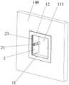
图1是本发明具体实施方式提供的接线盒在一视角下的结构示意图;1 is a schematic structural diagram of a junction box provided by a specific embodiment of the present invention from a viewing angle;
图2是本发明具体实施方式提供的接线盒在另一视角下的结构示意图;2 is a schematic structural diagram of a junction box provided by a specific embodiment of the present invention from another perspective;
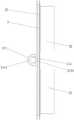
图3是本发明具体实施方式提供的接线盒安装在墙板上的结构示意图;3 is a schematic structural diagram of a junction box provided on a wall panel provided by a specific embodiment of the present invention;
图4是本发明具体实施方式提供的接线盒和墙板在又一视角下的结构示意图;4 is a schematic structural diagram of a junction box and a wall panel provided by a specific embodiment of the present invention from another perspective;
图5是本发明具体实施方式提供的接线盒中门体的侧视图。5 is a side view of a door body in a junction box provided by a specific embodiment of the present invention.
图中:In the picture:
1-安装座;2-门体;1-Mounting seat; 2-Door body;
11-安装筒;12-安装框;11-installation cylinder; 12-installation frame;
111-穿线槽;112-第一加强筋;111-threading groove; 112-first reinforcing rib;
121-第二加强筋;121 - the second reinforcing rib;
21-连接部;22-限位板;23-柔性部;24-成型槽;25-连接条;21-connecting part; 22-limiting plate; 23-flexible part; 24-forming groove; 25-connecting strip;
211-包围部;212-凸起部;211-surrounding part; 212-protruding part;
2111-包围空间;2112-观察口;2111-enclosed space; 2112-observation port;
2121-弧形凹槽;2121 - arc groove;
221-第三加强筋;221 - the third stiffener;
100-墙板。100 - Wall panels.
具体实施方式Detailed ways
为使本发明解决的技术问题、采用的技术方案和达到的技术效果更加清楚,下面将结合附图对本发明实施例的技术方案作进一步的详细描述,显然,所描述的实施例仅仅是本发明一部分实施例,而不是全部的实施例。基于本发明中的实施例,本领域技术人员在没有作出创造性劳动前提下所获得的所有其他实施例,都属于本发明保护的范围。In order to make the technical problems solved by the present invention, the technical solutions adopted and the technical effects achieved more clearly, the technical solutions of the embodiments of the present invention will be described in further detail below with reference to the accompanying drawings. Obviously, the described embodiments are only the present invention. Some examples, but not all examples. Based on the embodiments of the present invention, all other embodiments obtained by those skilled in the art without creative efforts shall fall within the protection scope of the present invention.
在本发明的描述中,需要说明的是,术语“中心”、“上”、“下”、“左”、“右”、“竖直”、“水平”、“内”、“外”等指示的方位或位置关系为基于附图所示的方位或位置关系,仅是为了便于描述本发明和简化描述,而不是指示或暗示所指的装置或元件必须具有特定的方位、以特定的方位构造和操作,因此不能理解为对本发明的限制。此外,术语“第一”、“第二”、仅用于描述目的,而不能理解为指示或暗示相对重要性。其中,术语“第一位置”和“第二位置”为两个不同的位置。In the description of the present invention, it should be noted that the terms "center", "upper", "lower", "left", "right", "vertical", "horizontal", "inner", "outer", etc. The indicated orientation or positional relationship is based on the orientation or positional relationship shown in the accompanying drawings, which is only for the convenience of describing the present invention and simplifying the description, rather than indicating or implying that the indicated device or element must have a specific orientation or a specific orientation. construction and operation, and therefore should not be construed as limiting the invention. Furthermore, the terms "first" and "second" are used for descriptive purposes only and should not be construed to indicate or imply relative importance. Therein, the terms "first position" and "second position" are two different positions.
在本发明的描述中,需要说明的是,除非另有明确的规定和限定,术语“安装”、“相连”、“连接”应做广义理解,例如,可以是固定连接,也可以是可拆卸连接;可以是机械连接,也可以是电连接;可以是直接相连,也可以通过中间媒介间接相连,可以是两个元件内部的连通。对于本领域的普通技术人员而言,可以具体情况理解上述术语在本发明中的具体含义。In the description of the present invention, it should be noted that the terms "installed", "connected" and "connected" should be understood in a broad sense, unless otherwise expressly specified and limited, for example, it may be a fixed connection or a detachable connection Connection; it can be a mechanical connection or an electrical connection; it can be a direct connection or an indirect connection through an intermediate medium, and it can be the internal communication of two components. For those of ordinary skill in the art, the specific meanings of the above terms in the present invention can be understood in specific situations.
如图1至图5所示,本实施例提供一种接线盒,能够有效防止触电事故,安全性高。该接线盒包括安装座1和门体2,安装座1上设置有穿线槽111,两个门体2分别转动设置于穿线槽111内,闭合两个门体2能够封堵穿线槽111的槽口,转动两个门体2能够打开穿线槽111的槽口。门体2上设置有连接部21,连接部21用于通过紧固件与开关面板固定连接。As shown in FIG. 1 to FIG. 5 , this embodiment provides a junction box, which can effectively prevent electric shock accidents and has high safety. The junction box includes a mounting seat 1 and a
该接线盒的使用方法大致为:如图1和图2所示,未安装开关面板时,两个门体2闭合,以封堵安装座1的穿线槽111的槽口,防止预埋的电线外露,避免发生人员触电事故,提高了接线盒的安全性能。如图3和图4所示,需要安装开关面板时,转动两个门体2,以打开穿线槽111的槽口,方便将预埋的电线与开关面板进行电连接。开关面板通过紧固件与门体2上的连接部21固定连接,安装方便快捷,连接稳固牢靠。The use method of the junction box is roughly as follows: as shown in Figure 1 and Figure 2, when the switch panel is not installed, the two
具体地,安装座1包括安装筒11,安装筒11的内侧壁围设形成穿线槽111,两个门体2分别转动设置于安装筒11的内侧壁上,安装筒11用于嵌入墙板100上的安装槽内,安装筒11的外侧壁与墙板100上的安装槽的内侧壁贴靠。穿线槽111大致为方形槽,为保持美观,方形槽的四个角均采用圆角过渡处理。两个门体2相互远离的左右侧边与安装筒11的内侧壁转动连接,两个门体2的上下侧边与安装筒11的内侧壁无直接连接关系,从而实现两个门体2转动时的开关门功能。Specifically, the mounting base 1 includes a mounting
进一步地,如图3所示,门体2与安装筒11的内侧壁之间通过柔性部23转动连接。柔性部23可以与门体2和安装筒11一体成型,加工制造方便。柔性部23的壁厚较薄,材质较软,采用柔性材料制成,方便受力变形,实现门体2与安装筒11的转动连接。当然,在其他实施例中,也可以采用合页等结构实现门体2与安装筒11的转动连接。Further, as shown in FIG. 3 , the
由于安装筒11的侧壁较薄,安装筒11的外侧壁上设置有多个第一加强筋112,以保证安装筒11的结构强度。第一加强筋112可以沿安装筒11的高度方向延伸,第一加强筋112的端部开设有倒角,避免划伤操作人员。Since the side wall of the
具体地,安装座1还包括与安装筒11连接的安装框12,安装框12套设于安装筒11的外侧壁上,安装框12用于与墙板100的前侧面贴靠,对安装筒11在墙板100上的安装位置进行限位。安装框12可以与安装筒11一体成型,也可以与安装筒11分体设置,分体设置时,安装框12与安装筒11可以过盈配合。安装框12的四个角分别设有圆角,避免划伤操作人员。Specifically, the mounting base 1 further includes a mounting
由于安装框12较薄,安装框12的内侧面设置有多个第二加强筋121,以保证安装框12的结构强度。安装框12的外侧面无需设置加强筋,避免影响外观平整美观。Since the
可选地,如图2和图4所示,门体2上设置有限位板22,门体2转动至与安装筒11的内侧壁贴靠时,限位板22能够与墙板100的后侧面贴靠。限位板22与门体2垂直,墙板100夹在限位板22和安装框12之间,保证了整个接线盒的稳固牢靠。限位板22上还可以设置多个第三加强筋221,以加强限位板22的结构强度,第三加强筋221可以为三角板结构,三角板结构的一个直角边与门体2连接,另一个直角边与限位板22连接。为方便加工制造,第三加强筋221可以与限位板22一体成型。Optionally, as shown in FIG. 2 and FIG. 4 , a limiting
具体地,如图5所示,连接部21包括凸设于门体2上的包围部211和凸起部212,呈拱桥状的包围部211形成有包围空间2111,凸起部212位于包围空间2111内,凸起部212上设置有弧形凹槽2121,弧形凹槽2121与包围部211围设形成圆柱形通道,圆柱形通道用于穿设紧固件,圆柱形通道的内壁上可以设置螺纹,方便与螺钉等紧固件进行螺纹配合。包围部211和凸起部212分别可以与门体2一体注塑成型,加工简单,便于批量加工。包围部211和凸起部212分别沿门体2的宽度方向延伸,方便后续转动门体2后,圆柱形通道正对需要连接的紧固件。包围部211的两端采用圆角过渡处理,保证美观的同时,还可以避免划伤操作人员。Specifically, as shown in FIG. 5 , the connecting
为方便连接部21注塑成型完成后进行脱模,可选地,如图2所示,门体2上设置有成型槽24,成型槽24与包围空间2111连通。在本实施例中,成型槽24呈长条状,每个门体2上有两个成型槽24,两个成型槽24分别位于凸起部212的两侧。In order to facilitate demolding of the connecting
为方便操作人员观察紧固件在包围空间2111内的旋拧程度,可选地,包围部211上设置有观察口2112,观察口2112与包围空间2111连通。另外,观察口2112也可以作为成型孔,方便包围部211注塑成型完成后进行脱模。In order to facilitate the operator to observe the degree of screwing of the fastener in the surrounding
可选地,两个门体2之间连接有连接条25。未安装开关面板时,两个门体2通过连接条25连接而闭合,以封堵安装座1的穿线槽111的槽口,防止小孩误碰打开门体2。需要安装开关面板时,转动两个门体2之前,需要先剪断或割断两个门体2之间的连接条25。连接条25可以与两个门体2一体成型,便于加工制造。连接条25沿高度方向可以间隔设置有两个,既能保证两个门体2之间的连接强度够大,不至于误碰打开门体2,也能够保证连接条25足够细方便剪断或割断。Optionally, a connecting
本实施例提供的接线盒,未安装开关面板时,两个门体2闭合,以封堵安装座1的穿线槽111的槽口,防止预埋的电线外露,避免发生人员触电事故,提高了接线盒的安全性能,需要安装开关面板时,转动两个门体2,以打开穿线槽111的槽口,方便将预埋的电线与开关面板进行电连接,开关面板通过紧固件与门体2上的连接部21固定连接,安装方便快捷,连接稳固牢靠。In the junction box provided in this embodiment, when the switch panel is not installed, the two
本实施例还提供一种照明开关,包括开关面板以及上述的接线盒,开关面板通过紧固件与接线盒的连接部21固定连接,安全性高,结构简单,操作方便。This embodiment also provides a lighting switch, including a switch panel and the above-mentioned junction box. The switch panel is fixedly connected to the connecting
注意,上述仅为本发明的较佳实施例及所运用技术原理。本领域技术人员会理解,本发明不限于这里的特定实施例,对本领域技术人员来说能够进行各种明显的变化、重新调整和替代而不会脱离本发明的保护范围。因此,虽然通过以上实施例对本发明进行了较为详细的说明,但是本发明不仅仅限于以上实施例,在不脱离本发明构思的情况下,还可以包括更多其他等效实施例,而本发明的范围由所附的权利要求范围决定。Note that the above are only preferred embodiments of the present invention and applied technical principles. Those skilled in the art will understand that the present invention is not limited to the specific embodiments herein, and various obvious changes, readjustments and substitutions can be made by those skilled in the art without departing from the protection scope of the present invention. Therefore, although the present invention has been described in detail through the above embodiments, the present invention is not limited to the above embodiments, and can also include more other equivalent embodiments without departing from the concept of the present invention. The scope is determined by the scope of the appended claims.
Claims (10)
Priority Applications (1)
| Application Number | Priority Date | Filing Date | Title |
|---|---|---|---|
| CN202210591870.5ACN114865558B (en) | 2022-05-27 | 2022-05-27 | Junction box and lighting switch |
Applications Claiming Priority (1)
| Application Number | Priority Date | Filing Date | Title |
|---|---|---|---|
| CN202210591870.5ACN114865558B (en) | 2022-05-27 | 2022-05-27 | Junction box and lighting switch |
Publications (2)
| Publication Number | Publication Date |
|---|---|
| CN114865558Atrue CN114865558A (en) | 2022-08-05 |
| CN114865558B CN114865558B (en) | 2025-09-30 |
Family
ID=82641113
Family Applications (1)
| Application Number | Title | Priority Date | Filing Date |
|---|---|---|---|
| CN202210591870.5AActiveCN114865558B (en) | 2022-05-27 | 2022-05-27 | Junction box and lighting switch |
Country Status (1)
| Country | Link |
|---|---|
| CN (1) | CN114865558B (en) |
Citations (6)
| Publication number | Priority date | Publication date | Assignee | Title |
|---|---|---|---|---|
| US4906816A (en)* | 1987-05-22 | 1990-03-06 | Medistad Holland B.V. | Blood heating apparatus for heating plastic blood supply pouches |
| JPH10224945A (en)* | 1997-01-31 | 1998-08-21 | Takao Kubota | Electrical wiring box |
| CN205882608U (en)* | 2016-08-12 | 2017-01-11 | 河南省瑞腾塑胶制品有限公司 | Wiring magazine visor and wiring magazine subassembly |
| CN106887743A (en)* | 2017-01-17 | 2017-06-23 | 杭州知加网络科技有限公司 | A kind of touch-proof socket of children |
| CN213125479U (en)* | 2020-10-28 | 2021-05-04 | 上海皮尔萨管业有限公司 | Multi-functional line box convenient to concatenation |
| CN217508191U (en)* | 2022-05-27 | 2022-09-27 | 得力普乐士办公科技有限公司 | Junction box and lighting switch |
- 2022
- 2022-05-27CNCN202210591870.5Apatent/CN114865558B/enactiveActive
Patent Citations (6)
| Publication number | Priority date | Publication date | Assignee | Title |
|---|---|---|---|---|
| US4906816A (en)* | 1987-05-22 | 1990-03-06 | Medistad Holland B.V. | Blood heating apparatus for heating plastic blood supply pouches |
| JPH10224945A (en)* | 1997-01-31 | 1998-08-21 | Takao Kubota | Electrical wiring box |
| CN205882608U (en)* | 2016-08-12 | 2017-01-11 | 河南省瑞腾塑胶制品有限公司 | Wiring magazine visor and wiring magazine subassembly |
| CN106887743A (en)* | 2017-01-17 | 2017-06-23 | 杭州知加网络科技有限公司 | A kind of touch-proof socket of children |
| CN213125479U (en)* | 2020-10-28 | 2021-05-04 | 上海皮尔萨管业有限公司 | Multi-functional line box convenient to concatenation |
| CN217508191U (en)* | 2022-05-27 | 2022-09-27 | 得力普乐士办公科技有限公司 | Junction box and lighting switch |
Also Published As
| Publication number | Publication date |
|---|---|
| CN114865558B (en) | 2025-09-30 |
Similar Documents
| Publication | Publication Date | Title |
|---|---|---|
| CN217508191U (en) | Junction box and lighting switch | |
| CN114865558A (en) | A junction box and lighting switch | |
| KR20130022366A (en) | A hinge | |
| CN116988702A (en) | Hinge assembly for furniture | |
| CN216489029U (en) | Front door structure assembly and power distribution frame thereof | |
| WO2023178985A1 (en) | Connecting structure of upper track and decorative panel of curtain | |
| CN209804150U (en) | interactive intelligent panel, frame assembly and corner piece thereof | |
| CN211258357U (en) | Intelligent door | |
| CN201066498Y (en) | Novel infrared touch screen structure | |
| CN211370196U (en) | Door and window with outer frame provided with water blocking skirt | |
| JP2015105507A (en) | Resin-made window frame | |
| CN216894117U (en) | A frame structure and door and window device | |
| CN201507102U (en) | Aluminium alloy section bar subassembly | |
| CN221646636U (en) | Overlap joint lock body mechanism | |
| CN207517286U (en) | Control box and thin intelligent panel comprising same | |
| CN207427334U (en) | Thin intelligent flat plate | |
| CN220017888U (en) | Door body and refrigeration equipment with same | |
| CN219346982U (en) | Doors and refrigeration equipment for refrigeration equipment | |
| CN221546731U (en) | Door frame edge folding assembly matched with hidden closing line of invisible door and wall protection plate | |
| CN222376282U (en) | Adjustable wood-plastic door cover | |
| CN222217502U (en) | Cabinet corner structure and cabinet | |
| CN216517615U (en) | Handle door type | |
| CN216930478U (en) | An outer corner piece and intelligent interactive device | |
| CN211128508U (en) | Interactive Smart Tablet and Frame Components | |
| CN221920754U (en) | Electromagnetic shielding door |
Legal Events
| Date | Code | Title | Description |
|---|---|---|---|
| PB01 | Publication | ||
| PB01 | Publication | ||
| SE01 | Entry into force of request for substantive examination | ||
| SE01 | Entry into force of request for substantive examination | ||
| GR01 | Patent grant |