CN114862829A - Method, device, equipment and storage medium for positioning reinforcement binding points - Google Patents
Method, device, equipment and storage medium for positioning reinforcement binding pointsDownload PDFInfo
- Publication number
- CN114862829A CN114862829ACN202210601589.5ACN202210601589ACN114862829ACN 114862829 ACN114862829 ACN 114862829ACN 202210601589 ACN202210601589 ACN 202210601589ACN 114862829 ACN114862829 ACN 114862829A
- Authority
- CN
- China
- Prior art keywords
- image
- point
- unbound
- sample
- sample image
- Prior art date
- Legal status (The legal status is an assumption and is not a legal conclusion. Google has not performed a legal analysis and makes no representation as to the accuracy of the status listed.)
- Granted
Links
Images


Classifications
- G—PHYSICS
- G06—COMPUTING OR CALCULATING; COUNTING
- G06T—IMAGE DATA PROCESSING OR GENERATION, IN GENERAL
- G06T7/00—Image analysis
- G06T7/0002—Inspection of images, e.g. flaw detection
- G06T7/0004—Industrial image inspection
- G—PHYSICS
- G06—COMPUTING OR CALCULATING; COUNTING
- G06N—COMPUTING ARRANGEMENTS BASED ON SPECIFIC COMPUTATIONAL MODELS
- G06N3/00—Computing arrangements based on biological models
- G06N3/02—Neural networks
- G06N3/04—Architecture, e.g. interconnection topology
- G06N3/045—Combinations of networks
- G—PHYSICS
- G06—COMPUTING OR CALCULATING; COUNTING
- G06N—COMPUTING ARRANGEMENTS BASED ON SPECIFIC COMPUTATIONAL MODELS
- G06N3/00—Computing arrangements based on biological models
- G06N3/02—Neural networks
- G06N3/08—Learning methods
- G—PHYSICS
- G06—COMPUTING OR CALCULATING; COUNTING
- G06T—IMAGE DATA PROCESSING OR GENERATION, IN GENERAL
- G06T7/00—Image analysis
- G06T7/10—Segmentation; Edge detection
- G06T7/13—Edge detection
- G—PHYSICS
- G06—COMPUTING OR CALCULATING; COUNTING
- G06T—IMAGE DATA PROCESSING OR GENERATION, IN GENERAL
- G06T7/00—Image analysis
- G06T7/80—Analysis of captured images to determine intrinsic or extrinsic camera parameters, i.e. camera calibration
- G—PHYSICS
- G06—COMPUTING OR CALCULATING; COUNTING
- G06V—IMAGE OR VIDEO RECOGNITION OR UNDERSTANDING
- G06V10/00—Arrangements for image or video recognition or understanding
- G06V10/40—Extraction of image or video features
- G06V10/44—Local feature extraction by analysis of parts of the pattern, e.g. by detecting edges, contours, loops, corners, strokes or intersections; Connectivity analysis, e.g. of connected components
- G—PHYSICS
- G06—COMPUTING OR CALCULATING; COUNTING
- G06T—IMAGE DATA PROCESSING OR GENERATION, IN GENERAL
- G06T2207/00—Indexing scheme for image analysis or image enhancement
- G06T2207/20—Special algorithmic details
- G06T2207/20024—Filtering details
- G06T2207/20032—Median filtering
- G—PHYSICS
- G06—COMPUTING OR CALCULATING; COUNTING
- G06T—IMAGE DATA PROCESSING OR GENERATION, IN GENERAL
- G06T2207/00—Indexing scheme for image analysis or image enhancement
- G06T2207/20—Special algorithmic details
- G06T2207/20081—Training; Learning
- G—PHYSICS
- G06—COMPUTING OR CALCULATING; COUNTING
- G06T—IMAGE DATA PROCESSING OR GENERATION, IN GENERAL
- G06T2207/00—Indexing scheme for image analysis or image enhancement
- G06T2207/30—Subject of image; Context of image processing
- G06T2207/30108—Industrial image inspection
- G06T2207/30136—Metal
Landscapes
- Engineering & Computer Science (AREA)
- Physics & Mathematics (AREA)
- Theoretical Computer Science (AREA)
- General Physics & Mathematics (AREA)
- Computer Vision & Pattern Recognition (AREA)
- General Health & Medical Sciences (AREA)
- Artificial Intelligence (AREA)
- Computational Linguistics (AREA)
- Data Mining & Analysis (AREA)
- Evolutionary Computation (AREA)
- Biomedical Technology (AREA)
- Molecular Biology (AREA)
- Computing Systems (AREA)
- General Engineering & Computer Science (AREA)
- Biophysics (AREA)
- Mathematical Physics (AREA)
- Software Systems (AREA)
- Life Sciences & Earth Sciences (AREA)
- Health & Medical Sciences (AREA)
- Multimedia (AREA)
- Quality & Reliability (AREA)
- Image Analysis (AREA)
- Image Processing (AREA)
Abstract
Description
Translated fromChinese技术领域technical field
本申请涉及建筑技术领域,具体而言,涉及一种钢筋绑扎点定位方法、装置、设备及存储介质。The present application relates to the field of construction technology, and in particular, to a method, device, equipment and storage medium for locating a reinforcing bar binding point.
背景技术Background technique
钢筋绑扎作业是钢筋混凝土施工工艺的重要工序之一,其工作目标是预先为构造柱、挑梁等钢筋混凝土构件扎制钢筋框架。根据构件形态要求,将多条钢筋以横纵交叉方式间隔排布并绑扎,形成构件网架,通常称为“钢筋骨架”,便于对混凝土进行约束,加强构件的整体性。Rebar binding operation is one of the important processes of reinforced concrete construction technology. According to the requirements of the component shape, a plurality of steel bars are arranged and bound at intervals in a horizontal and vertical manner to form a component grid, which is usually called a "rebar skeleton", which is convenient for constraining the concrete and strengthening the integrity of the component.
执行绑扎作业时,可依据目标构件的形态,对钢筋骨架进行排布,工人手工使用绑扎钩或者自动钢筋绑扎机对未绑扎的交叉点进行绑扎,由于需要绑扎的交叉点众多,工人需要长期重复弯腰操作,劳动强度较大,易造成严重的身体劳损问题,并且,人工绑扎的效率较低。When performing the binding operation, the steel skeleton can be arranged according to the shape of the target component. The workers manually use binding hooks or automatic steel binding machines to bind the unbound intersections. Due to the large number of intersections that need to be bound, the workers need to repeat for a long time. The bending operation is labor-intensive, which is easy to cause serious physical strain problems, and the efficiency of manual binding is low.
发明内容SUMMARY OF THE INVENTION
本发明的目的在于,针对上述现有技术的不足,提供一种钢筋绑扎点定位方法、装置、设备及存储介质,以解决现有技术中人工绑扎的效率较低的问题。The purpose of the present invention is to provide a method, device, equipment and storage medium for locating steel bar binding points in view of the deficiencies of the above-mentioned prior art, so as to solve the problem of low efficiency of manual binding in the prior art.
为实现上述目的,本申请实施例采用的技术方案如下:To achieve the above purpose, the technical solutions adopted in the embodiments of the present application are as follows:
第一方面,本申请实施例提供一种钢筋绑扎点定位方法,该方法包括:In a first aspect, an embodiment of the present application provides a method for locating a reinforcing bar binding point, the method comprising:
获取双目相机中预设相机针对钢筋框架的采集图像,其中,所述钢筋框架为预先采用多根钢筋搭建的结构;acquiring an image captured by a preset camera in a binocular camera for a rebar frame, wherein the rebar frame is a structure constructed with a plurality of rebars in advance;
从所述采集图像中提取至少一个未绑扎点的目标图像;extracting at least one target image of an unbound point from the acquired image;
采用预先的轮廓提取算法,对每个未绑扎点的目标图像进行轮廓提取,得到所述每个未绑扎点的钢筋交叉轮廓;Using a pre-contour extraction algorithm, contour extraction is performed on the target image of each unbound point to obtain the cross contour of each unbound point of steel bars;
根据所述钢筋交叉轮廓的平面像素坐标,计算所述每个未绑扎点的平面像素坐标;Calculate the plane pixel coordinates of each unbound point according to the plane pixel coordinates of the cross contour of the reinforcing bars;
根据所述采集图像,采用预先训练的所述双目相机的深度估计模型进行处理,得到所述采集图像对应的视差图,其中,所述视差图包括:所述采集图像中各个像素点的视差值,每个像素点的视差值用于表征采用所述双目相机中两个相机采集所述每个像素点的像素偏差;According to the collected image, the pre-trained depth estimation model of the binocular camera is used for processing to obtain a disparity map corresponding to the collected image, wherein the disparity map includes: the visual angle of each pixel in the collected image difference value, the disparity value of each pixel point is used to represent the pixel deviation of each pixel point collected by the two cameras in the binocular camera;
根据所述每个未绑扎点的平面像素坐标以及所述采集图像对应的视差图,计算所述未绑扎点的空间坐标。According to the plane pixel coordinates of each unbound point and the disparity map corresponding to the captured image, the spatial coordinates of the unbound point are calculated.
可选地,所述采用预先的轮廓提取算法,对每个未绑扎点的目标图像进行轮廓提取,得到所述每个未绑扎点的钢筋交叉轮廓之前,所述方法还包括:Optionally, before the contour extraction is performed on the target image of each unbound point by using a pre-defined contour extraction algorithm, and before the cross contour of the reinforcing bars of each unbound point is obtained, the method further includes:
对所述目标图像进行灰度化处理,得到灰度图像;performing grayscale processing on the target image to obtain a grayscale image;
对所述灰度图像进行中值滤波,得到滤波图像;Perform median filtering on the grayscale image to obtain a filtered image;
对所述滤波图像进行二值化处理,得到二值化图像;Perform binarization processing on the filtered image to obtain a binarized image;
对所述二值化图像进行开运算,得到预处理图像;performing an open operation on the binarized image to obtain a preprocessed image;
所述轮廓提取算法为二值图像轮廓提取算法,所述采用预先的轮廓提取算法,对每个未绑扎点的目标图像进行轮廓提取,得到所述每个未绑扎点的钢筋交叉轮廓,包括:The outline extraction algorithm is a binary image outline extraction algorithm, and the pre-defined outline extraction algorithm is used to perform outline extraction on the target image of each unbound point to obtain the cross outline of the reinforcing bars of each unbound point, including:
采用所述二值图像轮廓提取算法,对所述预处理图像进行轮廓提取,得到所述每个未绑扎点的钢筋交叉轮廓。Using the binary image contour extraction algorithm, contour extraction is performed on the preprocessed image to obtain the cross contour of the reinforcing bars of each unbound point.
可选地,所述根据所述钢筋交叉轮廓的平面像素坐标,计算所述每个未绑扎点的平面像素坐标,包括:Optionally, calculating the plane pixel coordinates of each unbound point according to the plane pixel coordinates of the cross contour of the reinforcing bars, including:
根据所述钢筋交叉轮廓的平面像素坐标,采用预设的区域阈值,确定所述钢筋交叉轮廓中多个区域轮廓的角点像素坐标;According to the plane pixel coordinates of the cross contour of the reinforcing bars, a preset area threshold is used to determine the pixel coordinates of the corner points of the multiple area contours in the cross contour of the reinforcing bars;
根据所述多个区域轮廓的角点像素坐标,确定所述每个未绑扎点的平面像素坐标。According to the pixel coordinates of the corner points of the contours of the multiple regions, the plane pixel coordinates of each of the unbound points are determined.
可选地,所述深度估计模型包括:编码器、解码器;所述根据所述采集图像,采用预先训练的所述双目相机的深度估计模型进行处理,得到所述采集图像对应的视差图之前,所述方法还包括:Optionally, the depth estimation model includes: an encoder and a decoder; the pre-trained depth estimation model of the binocular camera is used for processing according to the collected image to obtain a disparity map corresponding to the collected image Before, the method further includes:
获取所述双目相机的多个样本图像对,每个样本图像对包括:所述双目相机中两个相机针对同一目标对象采集的两个图像;Acquiring a plurality of sample image pairs of the binocular camera, each sample image pair comprising: two images collected by two cameras in the binocular camera for the same target object;
采用所述编码器对所述每个样本图像中所述预设相机采集的图像进行编码处理,得到两组样本图像特征;Using the encoder to encode the images collected by the preset camera in each sample image, to obtain two sets of sample image features;
采用所述解码器对所述两组样本图像特征进行解码处理,得到两组样本视差图;Using the decoder to decode the two sets of sample image features to obtain two sets of sample disparity maps;
根据所述两组样本视差图,对所述每个样本图像对进行重构,得到重构后的样本图像对;Reconstructing each sample image pair according to the two sets of sample disparity maps to obtain a reconstructed sample image pair;
根据所述重构后的样本图像对,以及所述每个样本图像对,计算损失函数值;Calculate a loss function value according to the reconstructed sample image pair and each sample image pair;
根据所述损失函数值,调整所述深度估计模型的模型参数,并重新基于所述多个样本图像对进行模型训练,直至达到预设的停止迭代条件。According to the value of the loss function, the model parameters of the depth estimation model are adjusted, and model training is performed based on the plurality of sample image pairs again until a preset stop iteration condition is reached.
可选地,所述采用所述编码器对所述每个样本图像中所述预设相机采集的图像进行编码处理,得到两组样本图像特征,包括:Optionally, using the encoder to perform encoding processing on images collected by the preset camera in each sample image, to obtain two sets of sample image features, including:
采用所述编码器对所述每个样本图像中所述预设相机采集的图像进行多个尺度的编码处理,得到所述两组样本图像特征,其中,每组样本图像特征包括:所述多个尺度的样本图像特征;The encoder is used to perform encoding processing of multiple scales on the images collected by the preset camera in each sample image, to obtain the two sets of sample image features, wherein each set of sample image features includes: the multiple sets of sample image features. scale of sample image features;
所述采用所述解码器对所述两组样本图像特征进行解码处理,得到两组样本视差图,包括:The decoder is used to decode the two sets of sample image features to obtain two sets of sample disparity maps, including:
采用所述解码器对所述多个尺度的样本图像特征进行解码处理,得到所述两组样本视差图,每组样本视差图包括:所述多个尺度的样本视差图。The decoder is used to decode the sample image features of the multiple scales to obtain the two groups of sample disparity maps, where each group of sample disparity maps includes: the sample disparity maps of the multiple scales.
可选地,所述深度估计模型还包括:路径增强网络,所述根据所述两组样本视差图,对所述每个样本图像对进行重构,得到重构后的样本图像对之前,所述方法还包括:Optionally, the depth estimation model further includes: a path enhancement network, which reconstructs each sample image pair according to the two sets of sample disparity maps, and before obtaining the reconstructed sample image pair, the The method also includes:
采用所述路径增强网络对所述多个尺度的样本视差图对应的特征图进行所述多个尺度的下采样处理,并将每个尺度的下采样结果、相同尺度的特征图,与相同尺度的样本视差图进行融合,得到更新后的所述每个尺度的样本视差图;The path enhancement network is used to perform downsampling processing on the feature maps corresponding to the sample disparity maps of the multiple scales, and the downsampling results of each scale and the feature maps of the same scale are compared with the same scale. The sample disparity map is fused to obtain the updated sample disparity map of each scale;
所述根据所述两组样本视差图,对所述每个样本图像对进行重构,得到重构后的样本图像对,包括:Reconstructing each sample image pair according to the two sets of sample disparity maps to obtain a reconstructed sample image pair, including:
根据所述更新后的所述每个尺度的样本视差图,对所述每个样本图像对进行重构,得到重构后的样本图像对。According to the updated sample disparity map of each scale, each sample image pair is reconstructed to obtain a reconstructed sample image pair.
可选地,所述编码器包括:所述多个尺度的残差卷积层,每个尺度的残差卷积层包括多个残差结构,每个残差结构包括:卷积层和轻量级注意力机制;Optionally, the encoder includes: residual convolution layers of the multiple scales, the residual convolution layers of each scale include multiple residual structures, and each residual structure includes: a convolution layer and a light magnitude attention mechanism;
采用所述编码器对所述每个样本图像中所述预设相机采集的图像进行多个尺度的编码处理,得到所述两组样本图像特征,包括:The encoder is used to perform encoding processing of multiple scales on the images collected by the preset camera in each sample image, to obtain the two sets of sample image features, including:
根据所述多个尺度的残差卷积层,对所述预设相机采集的图像进行特征提取,得到所述两组样本图像特征。According to the residual convolution layers of the multiple scales, feature extraction is performed on the images collected by the preset camera to obtain the two sets of sample image features.
第二方面,本申请实施例提供一种钢筋绑扎点定位装置,包括:In a second aspect, an embodiment of the present application provides a device for locating a reinforcing bar binding point, including:
获取模块,获取双目相机中预设相机针对钢筋框架的采集图像,其中,所述钢筋框架为预先采用多根钢筋搭建的结构;an acquisition module for acquiring images captured by a preset camera in the binocular camera for the steel bar frame, wherein the steel bar frame is a structure constructed with a plurality of steel bars in advance;
第一提取模块,从所述采集图像中提取至少一个未绑扎点的目标图像;a first extraction module, for extracting at least one target image of an unbound point from the acquired image;
第二提取模块,采用预先的轮廓提取算法,对每个未绑扎点的目标图像进行轮廓提取,得到所述每个未绑扎点的钢筋交叉轮廓;The second extraction module adopts a pre-contour extraction algorithm to perform contour extraction on the target image of each unbound point, and obtains the cross contour of the steel bar of each unbound point;
第一计算模块,根据所述钢筋交叉轮廓的平面像素坐标,计算所述每个未绑扎点的平面像素坐标;The first calculation module, according to the plane pixel coordinates of the cross contour of the reinforcing bars, calculates the plane pixel coordinates of each of the unbound points;
处理模块,根据所述采集图像,采用预先训练的所述双目相机的深度估计模型进行处理,得到所述采集图像对应的视差图,其中,所述视差图包括:所述采集图像中各个像素点的视差值,每个像素点的视差值用于表征采用所述双目相机中两个相机采集所述每个像素点的像素偏差;The processing module uses the pre-trained depth estimation model of the binocular camera for processing according to the collected image, and obtains a disparity map corresponding to the collected image, wherein the disparity map includes: each pixel in the collected image The disparity value of the point, the disparity value of each pixel point is used to represent the pixel deviation of each pixel point collected by the two cameras in the binocular camera;
第二计算模块,根据所述每个未绑扎点的平面像素坐标以及所述采集图像对应的视差图,计算所述未绑扎点的空间坐标。The second calculation module calculates the spatial coordinates of the unbound points according to the plane pixel coordinates of each unbound point and the disparity map corresponding to the captured image.
第三方面,本申请实施例提供一种计算机设备,包括:存储介质和处理器,所述存储介质存储有所述处理器可执行的计算机程序,所述处理器执行所述计算机程序时实现上述第一方面的一种钢筋绑扎点定位方法。In a third aspect, an embodiment of the present application provides a computer device, including: a storage medium and a processor, where the storage medium stores a computer program executable by the processor, and the processor implements the above when executing the computer program A method for locating a reinforcing bar binding point in the first aspect.
第四方面,本申请实施例提供一种计算机可读存储介质,所述存储介质上存储有计算机程序,所述计算机程序被处理器运行时,实现上述第一方面的一种钢筋绑扎点定位方法。In a fourth aspect, an embodiment of the present application provides a computer-readable storage medium, where a computer program is stored on the storage medium, and when the computer program is run by a processor, the method for locating a reinforcing bar binding point according to the first aspect above is implemented. .
相对现有技术而言,本申请具有以下有益效果:Compared with the prior art, the present application has the following beneficial effects:
本申请实施例提供的一种钢筋绑扎点定位方法、装置、设备及存储介质,可通过获取双目相机中预设相机针对钢筋框架的采集图像,其中,钢筋框架为预先采用多根钢筋搭建的结构,从采集图像中提取至少一个未绑扎点的目标图像,采用预先的轮廓提取算法,对每个未绑扎点的目标图像进行轮廓提取,得到每个未绑扎点的钢筋交叉轮廓,根据钢筋交叉轮廓的平面像素坐标,计算每个未绑扎点的平面像素坐标,根据采集图像,采用预先训练的双目相机的深度估计模型进行处理,得到采集图像对应的视差图,其中,视差图包括:采集图像中各个像素点的视差值,每个像素点的视差值用于表征采用双目相机中两个相机采集每个像素点的像素偏差,根据每个未绑扎点的平面像素坐标以及采集图像对应的视差图,计算未绑扎点的空间坐标,使得钢筋绑扎机器人可根据未绑扎点的空间坐标,进行自动化钢筋绑扎工作,提高钢筋绑扎的效率,通过机器的自动化代替人力,有效提高了钢筋绑扎的效率。The method, device, device, and storage medium for locating steel bar binding points provided by the embodiments of the present application can acquire images captured by a preset camera in a binocular camera for a steel bar frame, wherein the steel bar frame is pre-built with a plurality of steel bars. Structure, extract the target image of at least one unbound point from the acquired image, and use the pre-contour extraction algorithm to extract the outline of the target image of each unbound point to obtain the cross contour of each unbound point. The plane pixel coordinates of the contour are calculated, and the plane pixel coordinates of each unbound point are calculated. According to the collected images, the depth estimation model of the pre-trained binocular camera is used for processing, and the disparity map corresponding to the collected images is obtained, wherein the disparity map includes: The disparity value of each pixel point in the image, the disparity value of each pixel point is used to characterize the pixel deviation of each pixel point collected by two cameras in the binocular camera, according to the plane pixel coordinates of each unbound point and the acquisition The disparity map corresponding to the image calculates the spatial coordinates of the unbound points, so that the rebar tying robot can perform automatic rebar tying work according to the spatial coordinates of the unbound points, and improve the efficiency of rebar tying. Banding efficiency.
附图说明Description of drawings
为了更清楚地说明本发明实施例的技术方案,下面将对实施例中所需要使用的附图作简单地介绍,应当理解,以下附图仅示出了本发明的某些实施例,因此不应被看作是对范围的限定,对于本领域普通技术人员来讲,在不付出创造性劳动的前提下,还可以根据这些附图获得其他相关的附图。In order to illustrate the technical solutions of the embodiments of the present invention more clearly, the following briefly introduces the accompanying drawings used in the embodiments. It should be understood that the following drawings only show some embodiments of the present invention, and therefore do not It should be regarded as a limitation of the scope, and for those of ordinary skill in the art, other related drawings can also be obtained according to these drawings without any creative effort.
图1为本申请实施例提供的一种钢筋绑扎机器人框架的示意图;1 is a schematic diagram of a steel bar binding robot frame provided by an embodiment of the present application;
图2为本申请实施例提供的一种双目视觉系统的示意图;2 is a schematic diagram of a binocular vision system provided by an embodiment of the present application;
图3为本申请实施例提供的一种钢筋绑扎点定位方法的流程示意图;3 is a schematic flowchart of a method for locating a reinforcing bar binding point according to an embodiment of the present application;
图4为本申请实施例提供的一种提取目标图像的示意图;4 is a schematic diagram of an extraction target image provided by an embodiment of the present application;
图5为本申请实施例提供的一种提取钢筋交叉轮廓的示意图;FIG. 5 is a schematic diagram of extracting cross contours of steel bars according to an embodiment of the present application;
图6为本申请实施例提供的一种未绑扎点的空间坐标的示意图;6 is a schematic diagram of spatial coordinates of an unbound point provided by an embodiment of the present application;
图7为本申请实施例提供的一种目标图像的预处理方法的流程示意图;7 is a schematic flowchart of a method for preprocessing a target image provided by an embodiment of the present application;
图8为本申请实施例提供的一种计算未绑扎点的平面像素坐标方法的流程示意图;8 is a schematic flowchart of a method for calculating plane pixel coordinates of unbound points according to an embodiment of the present application;
图9为本申请实施例提供的一种未绑扎点的平面像素坐标的示意图;9 is a schematic diagram of plane pixel coordinates of an unbound point according to an embodiment of the present application;
图10为本申请实施例提供的一种训练深度估计模型方法的流程示意图;10 is a schematic flowchart of a method for training a depth estimation model provided by an embodiment of the present application;
图11为本申请实施例提供的一种深度估计Monodepth模型的示意图;11 is a schematic diagram of a depth estimation Monodepth model provided by an embodiment of the present application;
图12为本申请实施例提供的一种深度估计模型的示意图;12 is a schematic diagram of a depth estimation model provided by an embodiment of the present application;
图13为本申请实施例提供的一种特征融合的示意图;13 is a schematic diagram of a feature fusion provided by an embodiment of the present application;
图14为本申请实施例提供的一种残差卷积层的示意图;FIG. 14 is a schematic diagram of a residual convolution layer provided by an embodiment of the present application;
图15为本申请实施例提供的一种轻量级注意力机制的示意图;15 is a schematic diagram of a lightweight attention mechanism provided by an embodiment of the present application;
图16为本申请实施例提供的一种钢筋绑扎点定位装置的示意图;16 is a schematic diagram of a reinforcing bar binding point positioning device provided by an embodiment of the application;
图17为本申请实施例提供的一种计算机设备的示意图。FIG. 17 is a schematic diagram of a computer device according to an embodiment of the present application.
具体实施方式Detailed ways
为使本发明实施例的目的、技术方案和优点更加清楚,下面将结合本申请实施例中的附图,对本申请实施例中的技术方案进行清楚、完整地描述,显然,所描述的实施例是本申请一部分实施例,而不是全部的实施例。通常在此处附图中描述和示出的本申请实施例的组件可以以各种不同的配置来布置和设计。In order to make the purposes, technical solutions and advantages of the embodiments of the present invention clearer, the technical solutions in the embodiments of the present application will be clearly and completely described below with reference to the accompanying drawings in the embodiments of the present application. Obviously, the described embodiments It is a part of the embodiments of the present application, but not all of the embodiments. The components of the embodiments of the present application generally described and illustrated in the drawings herein may be arranged and designed in a variety of different configurations.
因此,以下对在附图中提供的本申请的实施例的详细描述并非旨在限制要求保护的本申请的范围,而是仅仅表示本申请的选定实施例。基于本申请中的实施例,本领域普通技术人员在没有作出创造性劳动前提下所获得的所有其它实施例,都属于本申请保护的范围。Thus, the following detailed description of the embodiments of the application provided in the accompanying drawings is not intended to limit the scope of the application as claimed, but is merely representative of selected embodiments of the application. Based on the embodiments in the present application, all other embodiments obtained by those of ordinary skill in the art without creative work fall within the protection scope of the present application.
钢筋绑扎作业是钢筋混凝土施工工艺的重要工序之一,为了提高钢筋绑扎的效率,可通过钢筋绑扎机器人进行钢筋绑扎,钢筋绑扎机器人进行钢筋绑扎前,需要对钢筋的未绑扎点进行定位,得到未绑扎点的位置信息,此时,钢筋绑扎机器人可对该位置信息对应的未绑扎的钢筋进行绑扎工作,相比人工对钢筋进行绑扎,通过钢筋绑扎机器人以及未绑扎点的位置信息,可以实现钢筋绑扎的自动化操作,大大提高钢筋绑扎的效率。Rebar binding operation is one of the important processes of reinforced concrete construction process. In order to improve the efficiency of steel bar binding, steel bar binding robots can be used to bind steel bars. The position information of the binding point. At this time, the steel bar binding robot can bind the unbound steel bar corresponding to the position information. Compared with the manual binding of the steel bar, the steel bar binding robot and the position information of the unbinding point can realize the steel bar. The automatic operation of binding greatly improves the efficiency of steel binding.
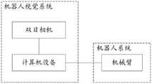
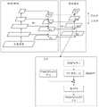
本申请的方案中,可通过钢筋绑扎机器人实现钢筋绑扎,本申请实施例提供一种钢筋绑扎机器人的框架,实现对未绑扎的钢筋进行绑扎,图1为本申请实施例提供的一种钢筋绑扎机器人框架的示意图,如图1所示,钢筋绑扎机器人包括机器人视觉系统、机器人系统两部分,首先通过机器人视觉系统的双目相机对钢筋绑扎点进行图像采集,然后由计算机设备进行钢筋绑扎点的定位,随后,计算机设备控制机械臂运动至未绑扎点位置,最后由绑扎模块完成钢筋绑扎。In the solution of the present application, steel bar binding can be realized by a steel bar binding robot. The embodiment of the present application provides a framework of a steel bar binding robot to bind unbound steel bars. FIG. 1 is a steel bar binding provided by an embodiment of the present application. The schematic diagram of the robot frame, as shown in Figure 1, the steel bar binding robot includes two parts: the robot vision system and the robot system. First, the image acquisition of the steel bar binding point is carried out by the binocular camera of the robot vision system, and then the computer equipment is used for the steel bar binding point. After positioning, the computer equipment controls the movement of the robotic arm to the position of the unbinding point, and finally the binding module completes the reinforcement of the reinforcement.
机器人视觉系统可以利用视觉系统精准、快速地识别定位钢筋绑扎点,可为后续机器人运动以及绑扎工作提供更好的支持,因此选择合适的视觉系统非常重要。本申请实施例中采用的双目视觉系统可以利用双目相机采集图像,图像信息丰富,立体匹配效果好,通过双目立体视觉技术可直接计算出目标物体的空间三维坐标,定位精度高,对光照强度的抗干扰性强。The robot vision system can use the vision system to accurately and quickly identify and locate the rebar binding points, which can provide better support for the subsequent robot movement and binding work. Therefore, it is very important to choose a suitable vision system. The binocular vision system adopted in the embodiment of the present application can use a binocular camera to collect images, the image information is rich, and the stereo matching effect is good. The anti-interference of light intensity is strong.
图2为本申请实施例提供的一种双目视觉系统的示意图,如图2所示,双目视觉系统的硬件设备由两个CMOS相机组成的双目相机以及固定支架构成,将双目相机固定在铝型材上,采用悬挂方式固定在钢筋绑扎平台的上方,将相机调整至与钢筋绑扎平台平行的位置。示例地,CMOS相机可为首爵USB型相机,该相机具有成本低、安装简单等优点,其分辨率为1280*720,焦距为4.9mm,刷新率为30FPS,当然,还可以为其它CMOS相机,在本申请实施例中不作具体限制。FIG. 2 is a schematic diagram of a binocular vision system provided by an embodiment of the application. As shown in FIG. 2 , the hardware device of the binocular vision system is composed of a binocular camera composed of two CMOS cameras and a fixed bracket. It is fixed on the aluminum profile, and it is fixed on the top of the steel binding platform by means of suspension, and the camera is adjusted to a position parallel to the steel binding platform. For example, the CMOS camera can be a Shoujue USB type camera, which has the advantages of low cost and simple installation. Its resolution is 1280*720, the focal length is 4.9mm, and the refresh rate is 30FPS. There is no specific limitation in the embodiments of the present application.
可选地,考虑到实验室机器人的活动范围,为了避免机器人移动与双目相机发生碰撞,可将双目相机固定在绑扎平台上方80cm处,对绑扎平面的有效采集范围为114.7cm*70.9cm,可有效覆盖机器人的活动范围。Optionally, considering the range of activities of the laboratory robot, in order to avoid the collision between the robot and the binocular camera, the binocular camera can be fixed 80cm above the binding platform, and the effective acquisition range of the binding plane is 114.7cm*70.9cm , which can effectively cover the range of motion of the robot.
机器人系统由机器人模块、绑扎模块组成。机器人模块负责控制机器人移动至指定位置,绑扎模块负责对绑扎点进行绑扎。The robot system consists of a robot module and a binding module. The robot module is responsible for controlling the robot to move to the designated position, and the binding module is responsible for binding the binding points.
机器人模块包括机器人本体、控制箱以及计算机设备等。机器人本体可根据计算机程序,移动到指定位置,并保持相对姿态。控制箱通过USB数据线接口与计算机设备连接,将接口标号输入到计算机设备的操作软件中,即可完成与计算机设备的连接,控制箱通过控制线与机器人本体连接。The robot module includes robot body, control box and computer equipment. The robot body can move to the designated position according to the computer program and maintain the relative posture. The control box is connected with the computer equipment through the USB data line interface, and the interface label is input into the operating software of the computer equipment to complete the connection with the computer equipment, and the control box is connected with the robot body through the control line.
可选地,本申请实施例采用的机器人本体可为AR3六自由度机器人,其质量轻、安装方便、操作简单、价格低,当然,还可以为其它机器人,在本申请实施例中不作具体限制。Optionally, the robot body used in the embodiments of the present application may be an AR3 six-degree-of-freedom robot, which is light in weight, convenient in installation, simple in operation, and low in price. Of course, it can also be other robots, which are not specifically limited in the embodiments of the present application. .
绑扎模块包括自动钢筋绑扎机、气动夹持器、气泵等。将自动钢筋绑扎机固定在机械臂的末端,在其按键处安装气动夹持器,并利用右侧双孔与气泵连接,对气泵进行气压控制以实现夹持器的开合。当机械臂末端移动到指定位置时,即钢筋的未绑扎点的位置,计算机设备发出指令,使气泵加压,带动夹持器闭合,以此控制自动钢筋绑扎机进行钢筋绑扎工作,完成对未绑扎钢筋点的绑扎,通过机器的自动化代替人力,可以有效提高钢筋绑扎的效率。The binding module includes automatic steel bar binding machine, pneumatic gripper, air pump, etc. Fix the automatic steel bar binding machine at the end of the mechanical arm, install a pneumatic gripper at the button, and use the right double hole to connect with the air pump, and control the air pump to realize the opening and closing of the gripper. When the end of the manipulator moves to the specified position, that is, the position of the unbinding point of the steel bar, the computer device sends an instruction to pressurize the air pump and drive the gripper to close, thereby controlling the automatic steel bar binding machine to perform the steel bar binding work and complete the unbinding work of the steel bar. The tying of steel bar points can effectively improve the efficiency of steel bar binding by replacing manpower with the automation of machines.
为了实现对钢筋绑扎点的定位,使得钢筋绑扎机器人根据未绑扎点的定位信息,进行自动化钢筋绑扎,提高钢筋绑扎的效率,本申请的方案中,提供一种钢筋绑扎点定位方法,可得到未绑扎点的定位,即位置信息。In order to realize the positioning of the steel bar binding points, so that the steel bar binding robot can automatically bind the steel bars according to the positioning information of the unbound points, and improve the efficiency of the steel bar binding, in the solution of the present application, a method for locating the steel bar binding points is provided, which can obtain the The location of the binding point, that is, the location information.
如下通过具体示例,对本申请实施例提供的一种钢筋绑扎点定位方法进行解释说明。图3为本申请实施例提供的一种钢筋绑扎点定位方法的流程示意图,如图3所示,该方法包括:The following describes a method for locating a reinforcing bar binding point provided by an embodiment of the present application by using a specific example. 3 is a schematic flowchart of a method for locating a reinforcing bar binding point according to an embodiment of the present application. As shown in FIG. 3 , the method includes:
S301,获取双目相机中预设相机针对钢筋框架的采集图像。S301 , acquiring an image captured by a preset camera in the binocular camera for the steel frame.
钢筋框架为预先采用多根钢筋搭建的结构。The reinforced frame is a structure constructed in advance with multiple steel bars.
双目相机可包含左视图相机和右视图相机,本申请实施例中可根据左视图相机拍摄的钢筋框架的左视图,确定钢筋的未绑扎点的位置信息。The binocular camera may include a left-view camera and a right-view camera. In this embodiment of the present application, the position information of the unbound point of the steel bar may be determined according to the left view of the steel bar frame captured by the left view camera.
可选地,相机采集图像前可进行相机标定,相机标定影响物体测量的精度,在获取物体空间三维信息过程中必不可少。双目相机标定是计算各个相机和相机间关系参数的过程,其中相机内参取决于自身内部元件,相机外参取决于两个相机间的位置。在本申请实施例中,通过制作标定板,在相机下改变其位置和角度,建立已知角点与图像中角点的关系,对相机内参和相机外参进行求解。当然,还可以为其它标定方法,如标准相机标定方法、相机主动标定方法、相机自标定方法等,在本申请实施例中不作具体限制。Optionally, camera calibration may be performed before the camera captures an image. Camera calibration affects the accuracy of object measurement and is essential in the process of acquiring spatial three-dimensional information of the object. Binocular camera calibration is the process of calculating the relationship parameters between each camera and the camera, in which the camera internal parameters depend on its own internal components, and the camera external parameters depend on the position between the two cameras. In the embodiment of the present application, by making a calibration board, changing its position and angle under the camera, establishing the relationship between the known corner points and the corner points in the image, and solving the camera internal parameters and camera external parameters. Of course, other calibration methods may also be used, such as a standard camera calibration method, an active camera calibration method, a camera self-calibration method, etc., which are not specifically limited in the embodiments of the present application.
利用标定后的双目相机采集钢筋绑扎点图像对,并进行相机畸变校正,获得双目相机针对钢筋框架的采集图像。其中,相机畸变可以称为镜头畸变,在实际应用中受镜头本身制作工艺限制以及光学透镜自身特性对成像的影响,目标物体与相机图像不再是单纯按比例缩小,而是存在视场角函数关系,这种函数是一种非线性变化,被称为镜头畸变,镜头畸变会使照片出现失真现象。因此,在相机标定时,需要采取校正措施提高相机拍摄的精度。The calibrated binocular camera is used to collect image pairs of rebar binding points, and the camera distortion correction is performed to obtain the image captured by the binocular camera for the rebar frame. Among them, camera distortion can be called lens distortion. In practical applications, due to the limitations of the manufacturing process of the lens itself and the influence of the characteristics of the optical lens on the imaging, the target object and the camera image are no longer simply scaled down, but there is a field angle function. relationship, this function is a non-linear change called lens distortion, and lens distortion can distort photos. Therefore, when the camera is calibrated, it is necessary to take corrective measures to improve the accuracy of camera shooting.
相机畸变可以分为三种类型,分别是径向畸变、切向畸变以及薄棱镜畸变,相机畸变的校正表达式如下述公式(1)所示:Camera distortion can be divided into three types, namely radial distortion, tangential distortion and thin prism distortion. The correction expression of camera distortion is shown in the following formula (1):

其中,(xl,yl)表示畸变后的坐标,(x,y)表示理想坐标,k1、k2、k3表示为径向畸变参数,r表示为空间点图像坐标到原点的距离,r可以表示为
S302,从采集图像中提取至少一个未绑扎点的目标图像。S302, extract at least one target image of an unbound point from the acquired image.
通过YOLOv4算法,可以得到未绑扎点的位置,该位置通过采集图像坐标轴的left、top、right、bottom四个数值表示目标框的位置,即目标框与原始图像四条边界的间距。图4为本申请实施例提供的一种提取目标图像的示意图,如图4所示,将未绑扎点的目标图像的四条边作为提取边,在采集图像中以目标图像的左上角坐标(left,top)为原点,采用图像裁剪的方法对目标图像进行提取,得到目标图像。Through the YOLOv4 algorithm, the position of the unbound point can be obtained. The position represents the position of the target frame by collecting the four values of left, top, right, and bottom of the image coordinate axis, that is, the distance between the target frame and the four boundaries of the original image. FIG. 4 is a schematic diagram of extracting a target image provided by an embodiment of the present application. As shown in FIG. 4 , the four sides of the target image without binding points are used as the extraction sides, and the upper left corner coordinate of the target image (left , top) is the origin, and the target image is extracted by the method of image cropping to obtain the target image.
S303,采用预先的轮廓提取算法,对每个未绑扎点的目标图像进行轮廓提取,得到每个未绑扎点的钢筋交叉轮廓。S303 , using a pre-contour extraction algorithm, perform contour extraction on the target image of each unbound point to obtain the cross-contour of the steel bar of each unbound point.
在本申请实施例中,预先的轮廓提取算法为FindContours算法,算法中认为一张图像由多个像素点(i,j)组成,利用f(i,j)表示像素点的灰度值,f(i,j)为0和1的像素分别表示0像素和1像素。In the embodiment of the present application, the pre-determined contour extraction algorithm is the FindContours algorithm. In the algorithm, it is considered that an image is composed of multiple pixel points (i, j), and f(i, j) is used to represent the gray value of the pixel point, f Pixels where (i, j) are 0 and 1 represent 0 pixels and 1 pixels, respectively.
FindContours算法的实现步骤为:The implementation steps of the FindContours algorithm are:
(1)假设输入图像为F={f(i,j)},设置第一条边界,采用光栅扫描法(即从左到右逐行扫描),若扫描到某个像素点(i,j)的灰度值f(i,j)≠0,则执行(2)步骤。(1) Assuming that the input image is F={f(i,j)}, set the first boundary, and use the raster scanning method (that is, scan line by line from left to right). If a certain pixel point (i,j) is scanned ) gray value f(i,j)≠0, then execute step (2).
(2)若扫描到某个像素点(i,j)满足预设外边界开始点条件时,则该像素点为外边界开始点,f(i2,j2)=f(i,j-1)。(2) If a certain pixel point (i, j) is scanned and satisfies the preset outer boundary start point condition, the pixel point is the outer boundary start point, f(i2, j2)=f(i, j-1) .
(3)以像素点(i,j)为中心,将(i2,j2)设定为起始点,以是否存在非0像素点为判断条件,在(i,j)邻域内按顺时针方向查找。若存在,则将第一个非0像素点记为(i1,j1),令f(i2,j2)=f(i1,j1),f(i3,j3)=f(i,j)。(3) Take the pixel point (i, j) as the center, set (i2, j2) as the starting point, and use whether there is a non-zero pixel point as the judgment condition, search clockwise in the neighborhood of (i, j) . If it exists, denote the first non-zero pixel point as (i1, j1), let f(i2, j2)=f(i1, j1), and f(i3, j3)=f(i, j).
(4)以像素点(i3,j3)为中心,将(i2,j2)的下一个点作为起始点,以是否存在非0像素点为判断条件,在(i3,j3)邻域内按逆时针方向查找。若存在,则将第一个非0像素点记为(i4,j4)。(4) Taking the pixel point (i3, j3) as the center, taking the next point of (i2, j2) as the starting point, and taking the existence of non-zero pixels as the judgment condition, in the neighborhood of (i3, j3), press counterclockwise Direction lookup. If it exists, the first non-zero pixel is recorded as (i4, j4).
(5)若f(i4,j4)=f(i,j)且f(i3,j3)=f(i1,j1),则进入(6)步骤,否则令f(i3,j3)=f(i2,j2),f(i4,j4)=f(i3,j3),返回到(4)步骤。(5) If f(i4,j4)=f(i,j) and f(i3,j3)=f(i1,j1), then go to step (6), otherwise let f(i3,j3)=f( i2, j2), f(i4, j4)=f(i3, j3), return to step (4).
(6)若f(i,j)≠1,利用光栅从下一个像素点(i,j+1)开始扫描,直到图像右下角的像素点被扫描。(6) If f(i,j)≠1, use the raster to scan from the next pixel point (i,j+1) until the pixel point in the lower right corner of the image is scanned.
图5为本申请实施例提供的一种提取钢筋交叉轮廓的示意图,如图5所示,FindContours算法根据上述算法步骤将每个未绑扎点的钢筋交叉的轮廓提取出来,并以多个平面像素坐标的形式进行输出。FIG. 5 is a schematic diagram of extracting the cross-contours of reinforcing bars provided by an embodiment of the present application. As shown in FIG. 5 , the FindContours algorithm extracts the cross-contours of reinforcing bars at each unbound point according to the above algorithm steps, and uses a plurality of plane pixels output in the form of coordinates.
S304,根据钢筋交叉轮廓的平面像素坐标,计算每个未绑扎点的平面像素坐标。S304, according to the plane pixel coordinates of the cross contour of the reinforcing bars, calculate the plane pixel coordinates of each unbound point.
通过未绑扎点的钢筋交叉轮廓中的多个平面像素坐标,可以通过计算得到每个未绑扎点的平面像素坐标。The plane pixel coordinates of each unbound point can be obtained by calculation through the multiple plane pixel coordinates in the cross contour of the reinforcing bars of the unbound points.
S305,根据采集图像,采用预先训练的双目相机的深度估计模型进行处理,得到采集图像对应的视差图。S305 , according to the collected image, the pre-trained depth estimation model of the binocular camera is used for processing to obtain a disparity map corresponding to the collected image.
将双目相机中预设相机针对钢筋框架的采集图像作为预先训练的双目相机的深度估计模型的输入,该模型的输出结果为采集图像对应的视差图。The image captured by the preset camera in the binocular camera for the steel frame is used as the input of the depth estimation model of the pre-trained binocular camera, and the output result of the model is the disparity map corresponding to the captured image.
其中,采集图像对应的视差图包括:采集图像中各个像素点的视差值,每个像素点的视差值用于表征采用双目相机中两个相机采集每个像素点的像素偏差。The disparity map corresponding to the collected image includes: disparity values of each pixel in the collected image, and the disparity value of each pixel is used to represent the pixel deviation of each pixel collected by two cameras in the binocular camera.
S306,根据每个未绑扎点的平面像素坐标以及采集图像对应的视差图,计算未绑扎点的空间坐标。S306: Calculate the spatial coordinates of the unbound points according to the plane pixel coordinates of each unbound point and the disparity map corresponding to the captured image.
根据每个未绑扎点的平面像素坐标,在采集图像对应的视差图中查询得到该未绑扎点的平面像素坐标对应的视差值,根据该视差值,可以计算得到该未绑扎点的空间坐标。According to the plane pixel coordinates of each unbound point, the disparity value corresponding to the plane pixel coordinates of the unbound point can be obtained by querying the disparity map corresponding to the captured image. According to the disparity value, the space of the unbound point can be calculated. coordinate.
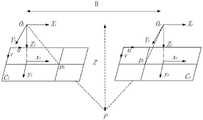
图6为本申请实施例提供的一种未绑扎点的空间坐标的示意图,如图6所示,利用放置在同一水平面、不同位置的双目相机对某一空间点进行拍摄时,左、右相机成像平面的投影点在x轴方向上存在距离偏差,这种偏差即为视差。双目测距是根据立体匹配算法对校正后的左右视图特征点匹配获得视差,利用三角形相似原理,测得物体在空间坐标系中的深度。两个型号相同的相机经过标定后处于同一平面,f表示相机焦距,P(X,Y,Z)为未绑扎点的空间坐标,Ol、Or分别为左右相机光心,Zl、Zr分别为左右相机的光轴,B是两个光心Ol和Or之间的距离,pl(xl,yl)、pr(xr,yr)为P点在左右成像平面上的投影点。FIG. 6 is a schematic diagram of the spatial coordinates of an unbound point provided by an embodiment of the present application. As shown in FIG. 6 , when a certain spatial point is photographed by using binocular cameras placed on the same horizontal plane and at different positions, the left and right The projection point of the camera imaging plane has a distance deviation in the x-axis direction, and this deviation is called parallax. Binocular ranging is based on the stereo matching algorithm to obtain the parallax by matching the corrected left and right view feature points, and using the triangle similarity principle to measure the depth of the object in the space coordinate system. Two cameras of the same model are in the same plane after calibration, f represents the focal length of the camera, P(X, Y, Z) is the spatial coordinate of the unbound point, Ol andOr are the optical centers of the left and right cameras, Zl , Zr is theopticalaxis of the left and rightcameras,B is the distance between the two opticalcenters Ol andOr Projection point on the plane.
根据三角形相似原理,空间点P在两成像平面上的投影点横坐标xl和xr可表示为下述公式(2)和下述公式(3):According to the triangle similarity principle, the abscissas xl and xr of the projection points of the space point P on the two imaging planes can be expressed as the following formula (2) and the following formula (3):


两成像平面上投影点的视差值d可表示为下述公式(4):The parallax value d of the projection points on the two imaging planes can be expressed as the following formula (4):

则空间点P距离相机的深度值Z可表示为下述公式(5):Then the depth value Z of the space point P from the camera can be expressed as the following formula (5):

计算出深度Z后,空间点P的X、Y轴坐标即可根据下述公式(6)求解:After calculating the depth Z, the X and Y axis coordinates of the space point P can be solved according to the following formula (6):

空间点P的X、Y轴坐标与像素坐标的关系如下述公式(7)所示:The relationship between the X and Y axis coordinates of the spatial point P and the pixel coordinates is shown in the following formula (7):

其中,uo、vo分别为图像坐标系原点在像素坐标系中的横纵坐标,fx、fy分别为在x、y轴方向的焦距。Wherein, uo and vo are the horizontal and vertical coordinates of the origin of the image coordinate system in the pixel coordinate system, respectively, and fx and fy are the focal lengths in the x and y axis directions, respectively.
根据上述公式即可求出未绑扎点P(X,Y,Z)的空间坐标,其中,P(X,Y,Z)的空间坐标的原点为左相机光心的位置,钢筋绑扎机器人可根据未绑扎点的空间坐标信息,进行自动化钢筋绑扎。According to the above formula, the spatial coordinates of the unbound point P(X,Y,Z) can be obtained, where the origin of the spatial coordinates of P(X,Y,Z) is the position of the optical center of the left camera. The spatial coordinate information of the unbound points is used for automatic reinforcement binding.
综上,本申请实施例提供的一种钢筋绑扎点定位方法,通过获取双目相机中预设相机针对钢筋框架的采集图像,从采集图像中提取至少一个未绑扎点的目标图像,采用预先的轮廓提取算法,对每个未绑扎点的目标图像进行轮廓提取,得到每个未绑扎点的钢筋交叉轮廓,根据钢筋交叉轮廓的平面像素坐标,计算每个未绑扎点的平面像素坐标,根据采集图像,采用预先训练的双目相机的深度估计模型进行处理,得到采集图像对应的视差图,根据每个未绑扎点的平面像素坐标以及采集图像对应的视差图,计算未绑扎点的空间坐标,使得钢筋绑扎机器人可根据未绑扎点的空间坐标,进行自动化钢筋绑扎工作,提高钢筋绑扎的效率,通过机器的自动化代替人力,有效提高了钢筋绑扎的效率。To sum up, the embodiment of the present application provides a method for locating a reinforcing bar binding point, by acquiring an image captured by a preset camera in a binocular camera for a steel bar frame, and extracting at least one target image of an unbinding point from the captured image, using a pre-set image. The contour extraction algorithm extracts the contour of the target image of each unbound point, and obtains the cross contour of each unbound point. The image is processed by the depth estimation model of the pre-trained binocular camera to obtain the disparity map corresponding to the collected image. According to the plane pixel coordinates of each unbound point and the disparity map corresponding to the collected image, the spatial coordinates of the unbound point are calculated. The steel bar binding robot can perform automatic steel bar binding work according to the spatial coordinates of the unbinding points, which improves the efficiency of steel bar binding. The automation of the machine replaces manpower, which effectively improves the efficiency of steel bar binding.
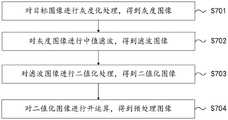
进一步地,在上述图3所示的一种钢筋绑扎点定位方法的基础上,本申请实施例还提供了一种目标图像的预处理方法。可选地,图7为本申请实施例提供的一种目标图像的预处理方法的流程示意图,如图7所示,对每个未绑扎点的目标图像进行轮廓提取前,还需要对每个未绑扎点的目标图像进行图像预处理,上述方法S303之前,即采用预先的轮廓提取算法,对每个未绑扎点的目标图像进行轮廓提取,得到每个未绑扎点的钢筋交叉轮廓之前,还包括:Further, on the basis of the method for locating a reinforcing bar binding point shown in FIG. 3 above, an embodiment of the present application further provides a method for preprocessing a target image. Optionally, FIG. 7 is a schematic flowchart of a method for preprocessing a target image provided by an embodiment of the present application. As shown in FIG. 7 , before performing contour extraction on the target image of each unbound point, it is also necessary to Image preprocessing is performed on the target image of the unbound points. Before the above-mentioned method S303, a pre-contour extraction algorithm is used to extract the outline of the target image of each unbound point, and before the cross contour of the steel bars of each unbound point is obtained, the include:
S701,对目标图像进行灰度化处理,得到灰度图像。S701 , performing grayscale processing on the target image to obtain a grayscale image.
相机采集图像时,会难以避免提取到冗余特征信息。同时受自身结构条件、内部元件的电磁干扰等影响会产生噪声。因此为消除冗余特征和噪声干扰,需要对图像预处理。When the camera collects images, it is difficult to avoid extracting redundant feature information. At the same time, it will generate noise due to its own structural conditions and the electromagnetic interference of internal components. Therefore, in order to eliminate redundant features and noise interference, image preprocessing is required.
图像灰度化是指利用数学运算将RGB三个颜色分量的数值进行重新求解的方法。本申请采用加权平均值法,根据人眼对三个颜色分量的感知度赋予不同的权重系数,并将乘积相加,加权平均值法的运算公式如下述公式(8)所示:Image grayscale refers to a method of re-solving the values of the three RGB color components using mathematical operations. The present application adopts the weighted average method to give different weight coefficients according to the perception of the three color components by the human eye, and adds the products. The calculation formula of the weighted average method is shown in the following formula (8):
g=α*R+β*G+γ*B 公式(8)g=α*R+β*G+γ*B Formula (8)
其中,g表示该像素点的灰度值,α、β、γ分别为三个颜色分量的权重系数,且,α、β、γ的和为1,R、G、B为三个分量的具体值,均在0~255范围内。Among them, g represents the gray value of the pixel, α, β, and γ are the weight coefficients of the three color components, and the sum of α, β, and γ is 1, and R, G, and B are the specific components of the three components. value, all in the range of 0 to 255.
S702,对灰度图像进行中值滤波,得到滤波图像。S702, performing median filtering on the grayscale image to obtain a filtered image.
中值滤波设定滤波窗口遍历图像像素,同时对窗口内所有像素按灰度值排列,选取灰度中值作为窗口中心像素点的灰度值。The median filter sets the filter window to traverse the image pixels, and at the same time, arranges all the pixels in the window according to the gray value, and selects the gray median value as the gray value of the center pixel of the window.
中值滤波器的表达式如下述公式(9)所示:The expression of the median filter is shown in the following formula (9):
g(x,y)=Med{f(x-k,y-l)|(k,l∈W)} 公式(9)g(x,y)=Med{f(x-k,y-l)|(k,l∈W)} Formula (9)
其中,g(x,y)、f(x,y)分别为输出和输入图片的灰度值,W表示滤波窗口。Among them, g(x, y) and f(x, y) are the grayscale values of the output and input images, respectively, and W represents the filtering window.
S703,对滤波图像进行二值化处理,得到二值化图像。S703: Perform binarization processing on the filtered image to obtain a binarized image.
二值化设定了灰度值阈值,将低于阈值的灰度值置为0,否则置为255,并对变换后的灰度值进行归一化,以此来减轻处理负担。根据阈值是否固定,二值化方法分为固定阈值二值化和自适应阈值二值化。前者具有操作简单、效率高等优点,但是无法显示局部特征;而后者能够显示局部特征,但计算繁琐、运行速度慢。本申请仅需要提取钢筋未绑扎点的轮廓,并不需要太多细节信息,因此采用固定阈值二值化方法,计算方法下述公式(10)所示:Binarization sets the gray value threshold, and sets the gray value below the threshold to 0, otherwise it is set to 255, and normalizes the transformed gray value to reduce the processing burden. According to whether the threshold is fixed, binarization methods are divided into fixed threshold binarization and adaptive threshold binarization. The former has the advantages of simple operation and high efficiency, but cannot display local features; while the latter can display local features, but the calculation is cumbersome and the running speed is slow. This application only needs to extract the outline of the unbound point of the steel bar, and does not need too much detailed information, so a fixed threshold binarization method is adopted, and the calculation method is shown in the following formula (10):

其中,g(x,y)表示二值化处理后的灰度值,f(x,y)为像素点的灰度值,T为设定阈值。Among them, g(x, y) represents the gray value after binarization, f(x, y) is the gray value of the pixel, and T is the set threshold.
S704,对二值化图像进行开运算,得到预处理图像。S704, perform an open operation on the binarized image to obtain a preprocessed image.
开运算采用先腐蚀运算后膨胀运算的操作方法,是图像形态学处理的基本方法之一。其中腐蚀是指按照所选用的几何结构,切断并去除与目标所覆盖像素相近的像素点;膨胀则是将周围相近的像素点与目标所覆盖像素进行连接。开运算能够清除孤立的点以及多余的毛刺等,但受到结构元素的影响,会出现不同的运算效果。Open operation adopts the operation method of first erosion operation and then dilation operation, which is one of the basic methods of image morphological processing. Among them, erosion refers to cutting off and removing pixels close to the pixels covered by the target according to the selected geometric structure; dilation refers to connecting nearby pixels with the pixels covered by the target. The open operation can remove isolated points and redundant burrs, etc., but different operation effects will appear due to the influence of structural elements.
在本申请实施例中,预先的轮廓提取算法二值图像轮廓提取算法,可以为FindContours算法,采用二值图像轮廓提取算法,对获得的预处理图像进行轮廓提取,可以得到每个未绑扎点的钢筋交叉轮廓。In the embodiment of the present application, the pre-set contour extraction algorithm binary image contour extraction algorithm may be the FindContours algorithm, and the binary image contour extraction algorithm is used to perform contour extraction on the obtained preprocessed image, and the contour of each unbound point can be obtained. Rebar cross profile.
本申请实施例提供的一种目标图像的预处理方法,通过对目标图像进行灰度化处理,得到灰度图像,对灰度图像进行中值滤波,得到滤波图像,对滤波图像进行二值化处理,得到二值化图像,对二值化图像进行开运算,得到预处理图像,可以消除目标图像中的冗余特征和噪声干扰。In a method for preprocessing a target image provided by an embodiment of the present application, grayscale processing is performed on the target image to obtain a grayscale image, median filtering is performed on the grayscale image to obtain a filtered image, and the filtered image is binarized After processing, a binarized image is obtained, and an open operation is performed on the binarized image to obtain a preprocessed image, which can eliminate redundant features and noise interference in the target image.
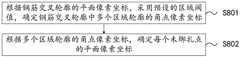
进一步地,在上述图3所示的一种钢筋绑扎点定位方法的基础上,本申请实施例还提供了一种计算未绑扎点的平面像素坐标的方法。可选地,图8为本申请实施例提供的一种计算未绑扎点的平面像素坐标方法的流程示意图,如图8所示,可根据钢筋交叉轮廓中多个区域的角点像素坐标,计算得到未绑扎点的平面像素坐标,上述方法S304,根据钢筋交叉轮廓的平面像素坐标,计算每个未绑扎点的平面像素坐标,包括:Further, on the basis of the method for locating a reinforcing bar binding point shown in FIG. 3, the embodiment of the present application further provides a method for calculating the plane pixel coordinates of the unbinding point. Optionally, FIG. 8 is a schematic flowchart of a method for calculating the plane pixel coordinates of an unbound point provided by an embodiment of the present application. As shown in FIG. 8 , according to the corner pixel coordinates of multiple areas in the cross contour of the reinforcing bars, the calculation To obtain the plane pixel coordinates of the unbound points, the above-mentioned method S304 calculates the plane pixel coordinates of each unbound point according to the plane pixel coordinates of the cross contour of the reinforcing bars, including:
S801,根据钢筋交叉轮廓的平面像素坐标,采用预设的区域阈值,确定钢筋交叉轮廓中多个区域轮廓的角点像素坐标。S801 , according to the plane pixel coordinates of the cross contour of the reinforcing bars, and using a preset area threshold, determine the pixel coordinates of the corner points of the contours of multiple areas in the cross contour of the reinforcing bars.
对于规则四边形物体,FindContours轮廓提取算法会以四个角点坐标(x,y)来表示四边形轮廓。但是螺纹钢筋属于边缘不规则的十字物体,如图5所示,利用轮廓提取函数会获得钢筋交叉与图像四条边所组成的四个不规则轮廓,同时边缘不规则会导致每个轮廓均存在多个轮廓角点,不利于后续钢筋绑扎点的确定。本申请通过轮廓角点选取方法来筛选最靠近钢筋交叉位置的轮廓角点。首先采用FindContours算法提取四个边缘不规则的四边形轮廓,每个轮廓由四个角周围的离散轮廓角点组成,即钢筋交叉轮廓的平面像素坐标,按照下述公式(11)~公式(14)可选取每个轮廓中最靠近钢筋交叉位置的角周围的离散轮廓角点。For regular quadrilateral objects, the FindContours contour extraction algorithm will use four corner coordinates (x, y) to represent the quadrilateral contour. However, threaded steel bars are cross objects with irregular edges. As shown in Figure 5, using the contour extraction function, four irregular contours composed of the cross of the steel bars and the four edges of the image will be obtained. A contour corner point is not conducive to the determination of the subsequent reinforcing bar binding points. The present application uses the contour corner selection method to screen the contour corners that are closest to the intersection of the reinforcing bars. First, the FindContours algorithm is used to extract four quadrilateral contours with irregular edges. Each contour is composed of discrete contour corner points around the four corners, that is, the plane pixel coordinates of the cross contour of the steel bar. According to the following formula (11) ~ formula (14) You can pick discrete profile corner points around the corner of each profile that is closest to where the bars cross.
左上角轮廓:Top left outline:

右上角轮廓:Top right outline:

左下角轮廓:Bottom left outline:

右下角轮廓:Bottom right outline:

其中,(xi,yi)为各个轮廓的轮廓角点,δ为区域阈值,i、j的取值为0,1,2等。Among them, (xi , yi ) are the contour corner points of each contour, δ is the regional threshold, and the values of i and j are 0, 1, 2, and so on.
由于在实际环境中钢筋交叉不能严格地保持垂直角度,因此本申请在算法中先以y坐标为筛选条件,选取出在区域阈值内的轮廓角点,再以x坐标为筛选条件进行筛选。如果先以x坐标作为筛选条件,在钢筋倾斜交叉时,某些轮廓靠近钢筋交叉位置的轮廓角点的x坐标并不能保证满足筛选条件,导致轮廓角点被筛选掉而产生较大误差。Since the cross of steel bars cannot strictly maintain the vertical angle in the actual environment, the present application first uses the y-coordinate as the screening condition in the algorithm, selects the contour corner points within the regional threshold, and then uses the x-coordinate as the screening condition for screening. If the x-coordinate is used as the screening condition first, the x-coordinates of the contour corners of some contours close to the intersection of the reinforcing bars cannot be guaranteed to satisfy the screening conditions when the bars are inclined and intersected, resulting in a large error caused by the contour corners being screened out.
将上述筛选后的每个轮廓的角点代入下述公式(15),分别求取钢筋交叉对应角周围离散轮廓角点的均值点,即钢筋交叉轮廓中多个区域轮廓的角点像素坐标。Substitute the above-screened corner points of each contour into the following formula (15), and obtain the mean point of discrete contour corner points around the corresponding corners of the steel bar intersection, that is, the corner pixel coordinates of multiple area contours in the steel bar intersection contour.

其中,(xi,yi)为筛选后各轮廓中靠近钢筋交叉位置的轮廓角点坐标,N为符合x和y阈值区域内的轮廓角点个数。Among them, (xi , yi ) are the coordinates of the contour corner points near the intersection of the steel bars in each contour after screening, and N is the number of contour corner points in the area that meets the x and y thresholds.
S802,根据多个区域轮廓的角点像素坐标,确定每个未绑扎点的平面像素坐标。S802: Determine the plane pixel coordinates of each unbound point according to the corner pixel coordinates of the contours of the multiple regions.
图9为本申请实施例提供的一种未绑扎点的平面像素坐标的示意图,如图9所示,将多个区域轮廓的角点像素坐标进行求均值计算,得到每个未绑扎点的平面像素坐标。FIG. 9 is a schematic diagram of the plane pixel coordinates of an unbound point provided by an embodiment of the present application. As shown in FIG. 9 , the pixel coordinates of the corner points of multiple area contours are averaged to obtain the plane of each unbound point. pixel coordinates.
本申请实施例提供的一种计算未绑扎点的平面像素坐标方法,根据钢筋交叉轮廓的平面像素坐标,采用预设的区域阈值,确定钢筋交叉轮廓中多个区域轮廓的角点像素坐标,根据多个区域轮廓的角点像素坐标,确定每个未绑扎点的平面像素坐标,进而可通过每个未绑扎点的平面像素坐标,确定每个未绑扎点的视差值,计算得到未绑扎点的空间坐标。In a method for calculating the plane pixel coordinates of the unbound points provided by the embodiment of the present application, according to the plane pixel coordinates of the cross contour of the reinforcing bars, a preset area threshold is used to determine the pixel coordinates of the corner points of the contours of multiple regions in the cross contour of the reinforcing bars, according to the The pixel coordinates of the corner points of the contours of multiple regions are used to determine the plane pixel coordinates of each unbound point, and then the disparity value of each unbound point can be determined through the plane pixel coordinates of each unbound point, and the unbound point can be obtained by calculation. space coordinates.
进一步的,在上述图3所示的一种钢筋绑扎点定位方法的基础上,本申请实施例还提供了一种训练深度估计模型的方法。可选地,图10为本申请实施例提供的一种训练深度估计模型方法的流程示意图,如图10所示,深度估计模型包括:编码器、解码器,上述方法S305之前,即采用预先训练的双目相机的深度估计模型进行处理,得到采集图像对应的视差图之前,还包括:Further, on the basis of the method for locating a reinforcing bar binding point shown in FIG. 3, an embodiment of the present application further provides a method for training a depth estimation model. Optionally, FIG. 10 is a schematic flowchart of a method for training a depth estimation model provided by an embodiment of the present application. As shown in FIG. 10 , the depth estimation model includes an encoder and a decoder. Before the above method S305, pre-training is adopted. Before processing the depth estimation model of the binocular camera to obtain the disparity map corresponding to the collected image, it also includes:
S1001,获取双目相机的多个样本图像对。S1001 , acquiring multiple sample image pairs of the binocular camera.
每个样本图像对包括:双目相机中两个相机针对同一目标对象采集的两个图像。Each sample image pair includes: two images collected by two cameras in the binocular camera for the same target object.
S1002,采用编码器对每个样本图像中预设相机采集的图像进行编码处理,得到两组样本图像特征。S1002 , using an encoder to perform encoding processing on images collected by a preset camera in each sample image, to obtain two sets of sample image features.
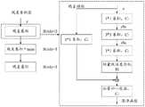
在本申请实施例中,深度估计模型采用深度估计Monodepth算法的网络框架,分为编码和解码两个过程,深度估计模型包括:编码器、解码器,在编码过程中,采用ResNet50作为主干特征提取网络。深度估计Monodepth算法采用无监督学习的方式,利用卷积神经网络实现端到端的深度估计。在训练期间利用双目相机获得的左右视图来代替深度图作为网络的真实背景深度标签,解决了深度图采集困难的问题。In the embodiment of the present application, the depth estimation model adopts the network framework of the depth estimation Monodepth algorithm, which is divided into two processes: encoding and decoding. The depth estimation model includes: an encoder and a decoder. In the encoding process, ResNet50 is used as the backbone feature extraction process. network. Depth estimation Monodepth algorithm adopts an unsupervised learning method and uses convolutional neural network to achieve end-to-end depth estimation. During training, the left and right views obtained by the binocular camera are used to replace the depth map as the real background depth labels of the network, which solves the problem of difficult depth map acquisition.
S1003,采用解码器对两组样本图像特征进行解码处理,得到两组样本视差图。S1003, using a decoder to decode the features of the two sets of sample images to obtain two sets of sample disparity maps.
在解码过程中,采用双线性插值(Bilinear Sampling)和上采样(Up-Sampling)后卷积的方式进行信息扩增。In the decoding process, information augmentation is performed by means of bilinear interpolation (Bilinear Sampling) and up-sampling (Up-Sampling) followed by convolution.
S1004,根据两组样本视差图,对每个样本图像对进行重构,得到重构后的样本图像对。S1004 , reconstructing each sample image pair according to the two sets of sample disparity maps to obtain a reconstructed sample image pair.
图11为本申请实施例提供的一种深度估计Monodepth模型的示意图,如图11所示,输入每个样本图像中预设相机采集的图像,得到两组样本视差图,包括一组以左视图为基底的左视差图和以右视图为基底的一组右视差图,将预设相机采集的图像与一组右视差图进行处理,得到重构后的一组右视图,将预设相机之外的另一个相机采集的图像与一组左视差图进行处理,得到重构后的一组左视图。重构后的样本图像对包括重构后的一组右视图和重构后的一组左视图。FIG. 11 is a schematic diagram of a depth estimation Monodepth model provided by an embodiment of the present application. As shown in FIG. 11 , an image collected by a preset camera in each sample image is input, and two sets of sample disparity maps are obtained, including one set with a left view The left disparity map as the base and a set of right disparity maps based on the right view, process the image collected by the preset camera and a set of right disparity maps to obtain a reconstructed set of right views, and use the preset camera as the base. The image captured by another camera is processed with a set of left disparity maps to obtain a reconstructed set of left views. The reconstructed sample image pair includes a reconstructed set of right views and a reconstructed set of left views.
S1005,根据重构后的样本图像对,以及每个样本图像对,计算损失函数值。S1005, according to the reconstructed sample image pair and each sample image pair, calculate a loss function value.
利用损失函数可获得重构视图与原视图之间的损失值,从而反向传播训练网络,将深度预测的问题转化为回归问题。The loss value between the reconstructed view and the original view can be obtained by using the loss function, so as to backpropagate the training network and transform the problem of depth prediction into a regression problem.
本申请实施例中,重构后的一组右视图中的一张右视图与重构后的一组左视图中对应的左视图的损失函数如下述公式(16)所示:In the embodiment of the present application, the loss function of a right view in the reconstructed group of right views and the corresponding left view in the reconstructed group of left views is shown in the following formula (16):

其中,


重构后的左视图的外观匹配损失函数可表示为下述公式(17):The appearance matching loss function of the reconstructed left view can be expressed as the following formula (17):

分别表示采集的左视图与重构左视图,α可以为0.85。represent the acquired left view and the reconstructed left view, respectively, and α can be 0.85.
重构后的左视图的异平滑度损失函数可表示为下述公式(18):The heterosmoothness loss function of the reconstructed left view can be expressed as the following formula (18):

其中,

由于图像深度的不连续性往往在图像的梯度上发生,因此采用权重项进行加权,使视差梯度随图像梯度增大而变大,以此获得全局平滑且边界明显的深度图。在本算法中对两组视差图均进行了梯度惩罚。Since the discontinuity of the image depth often occurs on the gradient of the image, the weighting term is used for weighting, so that the disparity gradient becomes larger with the increase of the image gradient, so as to obtain a globally smooth depth map with clear boundaries. In this algorithm, gradient penalty is applied to both sets of disparity maps.
重构后的左视图的左右视差一致性损失函数可表示为下述公式(19):The left-right disparity consistency loss function of the reconstructed left view can be expressed as the following formula (19):

其中,

由于在训练中只使用了左视图作为模型的输入,但输出为左右视图的视差,因此加入此损失函数能够使两个视差图尽可能地相似,这样就保证了左右视差的一致。Since only the left view is used as the input of the model in training, but the output is the disparity of the left and right views, adding this loss function can make the two disparity maps as similar as possible, thus ensuring the consistency of the left and right disparities.
S1006,根据损失函数值,调整深度估计模型的模型参数,并重新基于多个样本图像对进行模型训练,直至达到预设的停止迭代条件。S1006 , according to the value of the loss function, adjust the model parameters of the depth estimation model, and re-train the model based on a plurality of sample image pairs until a preset stop iteration condition is reached.
本申请实施例提供的一种训练深度估计模型方法,通过获取双目相机的多个样本图像对,每个样本图像对包括:双目相机中两个相机针对同一目标对象采集的两个图像,采用编码器对每个样本图像中预设相机采集的图像进行编码处理,得到两组样本图像特征,采用解码器对两组样本图像特征进行解码处理,得到两组样本视差图,根据两组样本视差图,对每个样本图像对进行重构,得到重构后的样本图像对,根据重构后的样本图像对,以及每个样本图像对,计算损失函数值,根据损失函数值,调整深度估计模型的模型参数,并重新基于多个样本图像对进行模型训练,直至达到预设的停止迭代条件,进而可通过训练的双目相机的深度估计模型处理采集图像,得到采集图像对应的视差图。In a method for training a depth estimation model provided by an embodiment of the present application, a plurality of sample image pairs of a binocular camera are acquired, and each sample image pair includes: two images collected by two cameras in the binocular camera for the same target object, The encoder is used to encode the images collected by the preset camera in each sample image to obtain two sets of sample image features, and the decoder is used to decode the two sets of sample image features to obtain two sets of sample disparity maps. Disparity map, reconstruct each sample image pair to obtain the reconstructed sample image pair, calculate the loss function value according to the reconstructed sample image pair and each sample image pair, and adjust the depth according to the loss function value Estimate the model parameters of the model, and re-train the model based on multiple sample image pairs until the preset stop iteration condition is reached, and then the acquired images can be processed by the depth estimation model of the trained binocular camera, and the corresponding disparity map of the acquired images can be obtained. .
进一步地,在上述图10所示的一种训练深度估计模型方法的基础上,本申请实施例还提供了另一种训练深度估计模型方法。可选地,上述方法S1002,采用编码器对每个样本图像中预设相机采集的图像进行编码处理,得到两组样本图像特征,包括:采用编码器对每个样本图像中预设相机采集的图像进行多个尺度的编码处理,得到两组样本图像特征。Further, on the basis of the above-mentioned method for training a depth estimation model shown in FIG. 10 , the embodiment of the present application further provides another method for training a depth estimation model. Optionally, in the above method S1002, using an encoder to perform encoding processing on images collected by a preset camera in each sample image, to obtain two sets of sample image features, comprising: using an encoder to perform encoding processing on images collected by a preset camera in each sample image. The image is encoded with multiple scales to obtain two sets of sample image features.
其中,每组样本图像特征包括:多个尺度的样本图像特征。Wherein, each group of sample image features includes: sample image features of multiple scales.
在编码的过程中,采用ResNet50作为主干特征提取网络,原图的尺寸每次经过残差卷积层resblock组合均会缩小一倍,以此获得多个不同尺度特征图,即,样本图像特征,直到特征图尺寸缩小为原图的1/64。In the encoding process, ResNet50 is used as the backbone feature extraction network, and the size of the original image will be doubled each time it passes through the residual convolution layer resblock combination, so as to obtain multiple feature maps of different scales, that is, the sample image features, Until the feature map size is reduced to 1/64 of the original image.
上述方法S1003,采用解码器对两组样本图像特征进行解码处理,得到两组样本视差图,包括:采用解码器对多个尺度的样本图像特征进行解码处理,得到两组样本视差图。In the above method S1003, using a decoder to decode two sets of sample image features to obtain two sets of sample disparity maps includes: using a decoder to decode sample image features of multiple scales to obtain two sets of sample disparity maps.
每组样本视差图包括:多个尺度的样本视差图。Each set of sample disparity maps includes: sample disparity maps of multiple scales.
将编码过程获得的特征图进行上采样扩大尺寸,通过残差连接与解码中的部分特征图拼接,得到尺寸分别为原图1/8、1/4、1/2以及与原图尺寸相同的4个特征图,之后经过卷积核为3*3的卷积层,生成对应不同尺寸的四个视差图。其中,对解码过程的最后三个特征图分别拼接时,需要加入上层获得的视差图。Upsampling the feature map obtained in the encoding process to enlarge the size, and splicing some feature maps in the decoding process through residual connection, the obtained size is 1/8, 1/4, 1/2 of the original image and the same size as the original image. Four feature maps are then passed through a convolutional layer with a convolution kernel of 3*3 to generate four disparity maps corresponding to different sizes. Among them, when splicing the last three feature maps of the decoding process respectively, the disparity map obtained by the upper layer needs to be added.
深度估计模型的输入为左视图,在本申请实施例中,输出为与原图尺寸相同的左视差图,进而通过左视差图实现未绑扎点的空间定位。The input of the depth estimation model is the left view, and in the embodiment of the present application, the output is a left disparity map with the same size as the original image, and the spatial positioning of the unbound points is further realized through the left disparity map.
进一步地,在上述图10所示的一种训练深度估计模型方法的基础上,本申请实施例还提供了另一种训练深度估计模型方法。图12为本申请实施例提供的一种深度估计模型的示意图,如图12所示,可选地,深度估计模型还包括:路径增强网络(Path AggregationNetwork,PAN),上述方法S1004之前,即根据两组样本视差图,对每个样本图像对进行重构,得到重构后的样本图像对之前,还包括:采用路径增强网络对多个尺度的样本视差图对应的特征图进行多个尺度的下采样处理,并将每个尺度的下采样结果、相同尺度的特征图,与相同尺度的样本视差图进行融合,得到更新后的每个尺度的样本视差图。Further, on the basis of the above-mentioned method for training a depth estimation model shown in FIG. 10 , the embodiment of the present application further provides another method for training a depth estimation model. FIG. 12 is a schematic diagram of a depth estimation model provided by an embodiment of the present application. As shown in FIG. 12 , optionally, the depth estimation model further includes: a Path Aggregation Network (PAN), before the above method S1004, according to Two sets of sample disparity maps, reconstructing each sample image pair, and before obtaining the reconstructed sample image pair, further comprising: using a path enhancement network to perform multiple scales of feature maps corresponding to the sample disparity maps of multiple scales. The downsampling process is performed, and the downsampling result of each scale, the feature map of the same scale, and the sample disparity map of the same scale are fused to obtain the updated sample disparity map of each scale.
为了解决Monodepth算法特征提取能力不足、梯度消失、定位误差大等问题,在解码过程中保留之前视差图上采样结构,为视差图提取更多特征,加入PAN结构,由Concatenation代替Addition作为特征融合方法,将浅层信息和深层信息融合,在提高网络模型特征提取能力的同时,加强了融合高低层特征的能力。In order to solve the problems of insufficient feature extraction capability, vanishing gradient, and large positioning error of the Monodepth algorithm, the previous disparity map upsampling structure is retained in the decoding process, and more features are extracted for the disparity map. The PAN structure is added, and Concatenation replaces Addition as the feature fusion method. , which fuses shallow information and deep information, and enhances the ability to fuse high and low-level features while improving the feature extraction capability of the network model.
标准的Monodepth网络在解码过程中采用自顶向下结构,虽然增强了语义特征,但经过多次传递,浅层定位信息出现大量丢失,这也导致了网络定位能力下降。因此本申请将PAN结构中的Bottom-up Path Augmentation策略与解码部分融合,添加自底向上的特征金字塔结构。图13为本申请实施例提供的一种特征融合的示意图,如图13所示,在下采样时,特征图均先通过卷积核尺寸为3*3的卷积调整,之后与横向连接的下一层同级的上采样信息进行拼接,再经过卷积层整合信息,得到下层特征图。深层特征图融合了更多强定位特征,提升了在多个尺度上的定位能力,从而提高了底层信息的利用率。The standard Monodepth network adopts a top-down structure in the decoding process. Although the semantic features are enhanced, after multiple passes, a large amount of shallow localization information is lost, which also leads to a decline in the network localization ability. Therefore, this application fuses the Bottom-up Path Augmentation strategy in the PAN structure with the decoding part, and adds a bottom-up feature pyramid structure. FIG. 13 is a schematic diagram of a feature fusion provided by an embodiment of the present application. As shown in FIG. 13 , during downsampling, the feature maps are first adjusted by convolution with a convolution kernel size of 3*3, and then combined with horizontally connected downlinks. The up-sampling information of the same level is spliced, and then the convolutional layer integrates the information to obtain the lower-level feature map. The deep feature map integrates more strong localization features, which improves the localization ability at multiple scales, thereby improving the utilization of the underlying information.
上述方法S1004,根据两组样本视差图,对每个样本图像对进行重构,得到重构后的样本图像对,包括:根据更新后的每个尺度的样本视差图,对每个样本图像对进行重构,得到重构后的样本图像对。In the above method S1004, reconstructing each sample image pair according to the two sets of sample disparity maps, to obtain a reconstructed sample image pair, including: according to the updated sample disparity maps of each scale, for each sample image pair Perform reconstruction to obtain reconstructed sample image pairs.
本申请实施例提供的一种深度估计模型,深度估计模型还包括:路径增强网络,根据两组样本视差图,对每个样本图像对进行重构,得到重构后的样本图像对之前,方法还包括:采用路径增强网络对多个尺度的样本视差图对应的特征图进行多个尺度的下采样处理,并将每个尺度的下采样结果、相同尺度的特征图,与相同尺度的样本视差图进行融合,得到更新后的每个尺度的样本视差图,根据两组样本视差图,对每个样本图像对进行重构,得到重构后的样本图像对,包括:根据更新后的每个尺度的样本视差图,对每个样本图像对进行重构,得到重构后的样本图像对,在提高网络模型特征提取能力的同时,加强了融合高低层特征的能力,提高了定位的准确性。A depth estimation model provided by an embodiment of the present application, the depth estimation model further includes: a path enhancement network, reconstructing each sample image pair according to two sets of sample disparity maps, and before obtaining the reconstructed sample image pair, the method It also includes: using a path enhancement network to perform multi-scale downsampling processing on the feature maps corresponding to the sample disparity maps of multiple scales, and compare the downsampling results of each scale, the feature maps of the same scale, and the sample disparity of the same scale. The images are fused to obtain the updated sample disparity map of each scale. According to the two groups of sample disparity maps, each sample image pair is reconstructed to obtain the reconstructed sample image pair, including: according to the updated sample image pair. The sample disparity map of the scale, reconstructs each sample image pair, and obtains the reconstructed sample image pair, which not only improves the feature extraction ability of the network model, but also strengthens the ability to integrate high and low-level features, and improves the accuracy of positioning. .
进一步地,在上述图12所示的一种深度估计模型的基础上,本申请实施例还提供了一种编码的方法。可选地,编码器包括:多个尺度的残差卷积层,每个尺度的残差卷积层包括多个残差结构,每个残差结构包括:卷积层和轻量级注意力机制。Further, on the basis of the depth estimation model shown in FIG. 12, an embodiment of the present application further provides an encoding method. Optionally, the encoder includes: residual convolution layers of multiple scales, the residual convolution layers of each scale include multiple residual structures, and each residual structure includes: a convolution layer and a lightweight attention mechanism.
残差模块的使用通常由数据规模和使用的残差网络深度所决定。当数据规模较小,使用的残差网络较浅时,如Resnet18、Resnet34,通常采用两个卷积层组成的残差模块。而当数据规模大,使用的残差网络较深时,如Resnet50、Resnet101、Resnet152,采用三层残差模块。由于本文所采用的钢筋绑扎点数据规模较大,模型复杂,并且考虑到网络的计算成本,本文在编码部分选用Resnet50网络模型,模型的残差卷积层resblock由融入CBAM(Convolutional Block Attention Module)轻量级注意力机制的resconv残差结构组成。The use of residual modules is usually determined by the size of the data and the depth of the residual network used. When the data size is small and the residual network used is shallow, such as Resnet18 and Resnet34, a residual module consisting of two convolutional layers is usually used. When the data scale is large and the residual network used is deep, such as Resnet50, Resnet101, and Resnet152, a three-layer residual module is used. Due to the large data scale of the steel bar binding point used in this paper, the complex model, and considering the computational cost of the network, this paper selects the Resnet50 network model in the coding part, and the residual convolution layer resblock of the model is integrated into CBAM (Convolutional Block Attention Module) Resconv residual structure composition of lightweight attention mechanism.
图14为本申请实施例提供的一种残差卷积层的示意图,如图14所示,在残差结构resconv中,输入特征图首先经过1*1的卷积降维,其次由3*3的卷积处理,再次使用1*1的卷积升维,经过CBAM提取关键特征生成新的特征图,最后将输入结果与残差结构的结果进行相加,经过批量归一化层(Batch Normalization,BN)和激活函数(elu),输出结果。添加CBAM不仅可以提高网络对特征提取的能力,而且防止了梯度消失。FIG. 14 is a schematic diagram of a residual convolution layer provided by an embodiment of the application. As shown in FIG. 14 , in the residual structure resconv, the input feature map is first subjected to 1*1 convolution to reduce the dimension, followed by 3* 3 convolution processing, again using 1*1 convolution to increase the dimension, extracting key features through CBAM to generate a new feature map, and finally adding the input results and the results of the residual structure, and going through a batch normalization layer (Batch Normalization, BN) and activation function (elu), output the result. Adding CBAM not only improves the ability of the network for feature extraction, but also prevents the gradient from vanishing.
CBAM是一种简单高效的轻量化注意力机制,利用通道和空间两种注意力模块,对关键特征进行更高效地提取。通道注意力模块会将权重分配给关键特征更多的通道,空间注意力模块会定位到关键特征更加丰富的区域,以此来提高在网络中提取关键信息的能力,图15为本申请实施例提供的一种轻量级注意力机制的示意图,如图15所示,特征图F输入网络后,首先经过全局最大池化和平均池化,其尺寸会被压缩,特征信息也会被整合,生成两个压缩特征图,由两层感知器(Multi-Layer Perceptron,MLP)对压缩特征图进行维度变换操作;其次利用加和操作处理输出特征,并经sigmoid激活;最后获得通道注意力权值Mc,计算公式如下述公式(20)所示:CBAM is a simple and efficient lightweight attention mechanism that utilizes both channel and spatial attention modules to extract key features more efficiently. The channel attention module will assign weights to channels with more key features, and the spatial attention module will locate areas with more key features, so as to improve the ability to extract key information in the network. Figure 15 is an embodiment of the application A schematic diagram of a lightweight attention mechanism is provided, as shown in Figure 15. After the feature map F is input to the network, it first undergoes global max pooling and average pooling, its size will be compressed, and feature information will also be integrated. Generate two compressed feature maps, and perform dimension transformation operations on the compressed feature maps by a two-layer perceptron (Multi-Layer Perceptron, MLP); secondly, use the sum operation to process the output features and activate them by sigmoid; finally obtain the channel attention weights Mc, the calculation formula is shown in the following formula (20):

其中,σ为sigmoid激活函数,W0和W1是多层感知机MLP中的权重,

特征图F经过通道注意力模块后产生新特征图F′,根据通道做全局平均池化和最大池化处理后,对特征图进行拼接和卷积操作,从而输出空间注意力加权系数Ms,将新特征F′与Ms相乘,生成最终特征图F″,如下述公式(21)所示:After the feature map F passes through the channel attention module, a new feature map F′ is generated. After global average pooling and maximum pooling are performed according to the channel, the feature map is spliced and convolutional operations are performed to output the spatial attention weighting coefficient Ms , The new feature F′ is multiplied by Ms to generate the final feature map F″, as shown in the following formula (21):

采用编码器对每个样本图像中预设相机采集的图像进行多个尺度的编码处理,得到两组样本图像特征,包括:根据多个尺度的卷积层,对预设相机采集的图像进行特征提取,得到两组样本图像特征。The encoder is used to encode the images collected by the preset camera in each sample image at multiple scales, and two sets of sample image features are obtained, including: according to the convolution layers of multiple scales, the image collected by the preset camera is characterized Extraction to obtain two sets of sample image features.
本申请实施例提供的一种编码方法,编码器包括:多个尺度的残差卷积层,每个尺度的残差卷积层包括多个残差结构,每个残差结构包括:卷积层和轻量级注意力机制,采用编码器对每个样本图像中预设相机采集的图像进行多个尺度的编码处理,得到两组样本图像特征,包括:根据多个尺度的残差卷积层,对预设相机采集的图像进行特征提取,得到两组样本图像特征,通过轻量级注意力机制的残差卷积层,不仅可以提高网络对特征提取的能力,而且防止了梯度消失,提高了定位的准确性。In an encoding method provided by an embodiment of the present application, the encoder includes: residual convolution layers of multiple scales, the residual convolution layers of each scale include multiple residual structures, and each residual structure includes: convolution Layer and lightweight attention mechanism, using the encoder to encode the images collected by the preset camera in each sample image at multiple scales, to obtain two sets of sample image features, including: residual convolution according to multiple scales layer, extract the features of the images collected by the preset camera, and obtain two sets of sample image features. The residual convolution layer of the lightweight attention mechanism can not only improve the network's ability to extract features, but also prevent the gradient from disappearing. Improved positioning accuracy.
通过路径增强网络以及轻量级注意力机制的残差卷积层,增加较少的网络参数量,解决了提取特征能力不足、浅层信息利用率低的问题,进一步地,提高了定位的准确性。Through the path enhancement network and the residual convolution layer of the lightweight attention mechanism, less network parameters are added, which solves the problems of insufficient feature extraction ability and low utilization of shallow information, and further improves the accuracy of positioning. sex.
本申请提供的一种钢筋绑扎点定位方法,在图像定位中,首先对未绑扎点目标图像进行提取和预处理,消除噪声干扰,更好地提取钢筋交叉的轮廓,其次采用轮廓提取算法提取钢筋轮廓,通过轮廓角点选取方法,筛选出最靠近钢筋交叉位置的轮廓角点,方便钢筋绑扎点图像定位,在空间定位中,提供一种改进的深度估计模型,首先在解码部分加入CBAM注意力机制,提高了对特征的提取能力,之后在解码部分引入PAN结构,增强对浅层定位特征的利用率,进一步增强了特征提取能力,可以提升钢筋绑扎点的定位精度。The present application provides a method for locating steel bar binding points. In the image positioning, firstly, the target image of the unbinding point is extracted and preprocessed to eliminate noise interference, so as to better extract the outline of the steel bar crossing, and secondly, the contour extraction algorithm is used to extract the steel bar. Contour, through the contour corner selection method, the contour corner points closest to the intersection of the steel bars are screened out, which is convenient for the image positioning of the steel bar binding points. In the spatial positioning, an improved depth estimation model is provided. First, add CBAM attention to the decoding part The mechanism improves the feature extraction capability, and then introduces the PAN structure in the decoding part to enhance the utilization of shallow positioning features, further enhance the feature extraction capability, and improve the positioning accuracy of the steel bar binding points.
下述对用以执行的本申请所提供的一种钢筋绑扎点定位装置进行说明,其具体的实现过程以及技术效果参见上述,下述不再赘述。The following describes a reinforcing bar binding point positioning device provided by the present application for execution, and the specific implementation process and technical effects thereof are referred to above, and will not be repeated below.
图16为本申请实施例提供的一种钢筋绑扎点定位装置的示意图,如图15所示,该钢筋绑扎点定位装置包括:FIG. 16 is a schematic diagram of a reinforcing bar binding point positioning device provided in an embodiment of the application. As shown in FIG. 15 , the reinforcing bar binding point positioning device includes:
获取模块1601,用于获取双目相机中预设相机针对钢筋框架的采集图像,其中,所述钢筋框架为预先采用多根钢筋搭建的结构。The acquiring
第一提取模块1602,用于从所述采集图像中提取至少一个未绑扎点的目标图像。The
第二提取模块1603,用于采用预先的轮廓提取算法,对每个未绑扎点的目标图像进行轮廓提取,得到所述每个未绑扎点的钢筋交叉轮廓。The
第一计算模块1604,用于根据所述钢筋交叉轮廓的平面像素坐标,计算所述每个未绑扎点的平面像素坐标。The
处理模块1605,用于根据所述采集图像,采用预先训练的所述双目相机的深度估计模型进行处理,得到所述采集图像对应的视差图,其中,所述视差图包括:所述采集图像中各个像素点的视差值,每个像素点的视差值用于表征采用所述双目相机中两个相机采集所述每个像素点的像素偏差。The
第二计算模块1606,用于根据所述每个未绑扎点的平面像素坐标以及所述采集图像对应的视差图,计算所述未绑扎点的空间坐标。The
可选地,第二提取模块1603具体用于对目标图像进行灰度化处理,得到灰度图像;对灰度图像进行中值滤波,得到滤波图像;对滤波图像进行二值化处理,得到二值化图像;对二值化图像进行开运算,得到预处理图像;轮廓提取算法为二值图像轮廓提取算法,采用预先的轮廓提取算法,对每个未绑扎点的目标图像进行轮廓提取,得到每个未绑扎点的钢筋交叉轮廓,包括:采用二值图像轮廓提取算法,对预处理图像进行轮廓提取,得到每个未绑扎点的钢筋交叉轮廓。Optionally, the
可选地,第一计算模块1604具体用于根据钢筋交叉轮廓的平面像素坐标,采用预设的区域阈值,确定钢筋交叉轮廓中多个区域轮廓的角点像素坐标;根据多个区域轮廓的角点像素坐标,确定每个未绑扎点的平面像素坐标。Optionally, the
可选地,处理模块1605具体用于获取双目相机的多个样本图像对,每个样本图像对包括:双目相机中两个相机针对同一目标对象采集的两个图像;采用编码器对每个样本图像中预设相机采集的图像进行编码处理,得到两组样本图像特征;采用解码器对两组样本图像特征进行解码处理,得到两组样本视差图;根据两组样本视差图,对每个样本图像对进行重构,得到重构后的样本图像对;根据重构后的样本图像对,以及每个样本图像对,计算损失函数值;根据损失函数值,调整深度估计模型的模型参数,并重新基于多个样本图像对进行模型训练,直至达到预设的停止迭代条件。Optionally, the
可选地,处理模块1605具体用于采用编码器对每个样本图像中预设相机采集的图像进行多个尺度的编码处理,得到两组样本图像特征,其中,每组样本图像特征包括:多个尺度的样本图像特征;采用解码器对两组样本图像特征进行解码处理,得到两组样本视差图,包括:采用解码器对多个尺度的样本图像特征进行解码处理,得到两组样本视差图,每组样本视差图包括:多个尺度的样本视差图。Optionally, the
可选地,处理模块1605具体用于采用路径增强网络对多个尺度的样本视差图对应的特征图进行多个尺度的下采样处理,并将每个尺度的下采样结果、相同尺度的特征图,与相同尺度的样本视差图进行融合,得到更新后的每个尺度的样本视差图;根据两组样本视差图,对每个样本图像对进行重构,得到重构后的样本图像对,包括:根据更新后的每个尺度的样本视差图,对每个样本图像对进行重构,得到重构后的样本图像对。Optionally, the
可选地,处理模块1605具体用于根据多个尺度的残差卷积层,对预设相机采集的图像进行特征提取,得到两组样本图像特征。Optionally, the
图17为本申请实施例提供的一种计算机设备的示意图,该计算机设备可以是具备计算处理功能的计算设备或服务器。FIG. 17 is a schematic diagram of a computer device according to an embodiment of the present application, where the computer device may be a computing device or a server with a computing processing function.
该计算机设备包括:处理器1701、存储介质1702、总线1703。处理器1701和存储介质1702通过总线1703连接。The computer device includes: a
存储介质1702用于存储程序,处理器1701调用存储介质1702存储的程序,以执行上述方法实施例。具体实现方式和技术效果类似,这里不再赘述。The
可选地,本发明还提供一种程序产品,例如计算机可读存储介质,包括程序,该程序在被处理器执行时用于执行上述方法实施例。Optionally, the present invention further provides a program product, such as a computer-readable storage medium, including a program, which is used to execute the foregoing method embodiments when executed by a processor.
在本发明所提供的几个实施例中,应该理解到,所揭露的装置和方法,可以通过其它的方式实现。例如,以上所描述的装置实施例仅仅是示意性的,例如,所述单元的划分,仅仅为一种逻辑功能划分,实际实现时可以有另外的划分方式,例如多个单元或组件可以结合或者可以集成到另一个系统,或一些特征可以忽略,或不执行。所述作为分离部件说明的单元可以是或者也可以不是物理上分开的,作为单元显示的部件可以是或者也可以不是物理单元,即可以位于一个地方,或者也可以分布到多个网络单元上。可以根据实际的需要选择其中的部分或者全部单元来实现本实施例方案的目的。In the several embodiments provided by the present invention, it should be understood that the disclosed apparatus and method may be implemented in other manners. For example, the apparatus embodiments described above are only illustrative. For example, the division of the units is only a logical function division. In actual implementation, there may be other division methods. For example, multiple units or components may be combined or Can be integrated into another system, or some features can be ignored, or not implemented. The units described as separate components may or may not be physically separated, and components displayed as units may or may not be physical units, that is, may be located in one place, or may be distributed to multiple network units. Some or all of the units may be selected according to actual needs to achieve the purpose of the solution in this embodiment.
上述以软件功能单元的形式实现的集成的单元,可以存储在一个计算机可读取存储介质中。上述软件功能单元存储在一个存储介质中,包括若干指令用以使得一台计算机设备(可以是个人计算机,服务器,或网络设备等)或处理器执行本发明各个实施例所述方法的部分步骤。而前述的存储介质包括:U盘、移动硬盘、只读存储器、随机存取存储器、磁碟或者光盘等各种可以存储程序代码的介质。The above-mentioned integrated units implemented in the form of software functional units can be stored in a computer-readable storage medium. The above-mentioned software functional units are stored in a storage medium, and include several instructions to cause a computer device (which may be a personal computer, a server, or a network device, etc.) or a processor to execute some steps of the methods described in the various embodiments of the present invention. The aforementioned storage medium includes: a U disk, a removable hard disk, a read-only memory, a random access memory, a magnetic disk or an optical disk and other media that can store program codes.
上仅为本申请的具体实施方式,但本申请的保护范围并不局限于此,任何熟悉本技术领域的技术人员在本申请揭露的技术范围内,可轻易想到变化或替换,都应涵盖在本申请的保护范围之内。因此,本申请的保护范围应以权利要求的保护范围为准。The above are only specific embodiments of the present application, but the protection scope of the present application is not limited to this. Any person skilled in the art who is familiar with the technical scope disclosed in the present application can easily think of changes or replacements, which should be covered within the scope of the present application. within the scope of protection of this application. Therefore, the protection scope of the present application shall be subject to the protection scope of the claims.
Claims (10)
Translated fromChinesePriority Applications (1)
| Application Number | Priority Date | Filing Date | Title |
|---|---|---|---|
| CN202210601589.5ACN114862829B (en) | 2022-05-30 | 2022-05-30 | Method, device, equipment and storage medium for positioning binding points of reinforcing steel bars |
Applications Claiming Priority (1)
| Application Number | Priority Date | Filing Date | Title |
|---|---|---|---|
| CN202210601589.5ACN114862829B (en) | 2022-05-30 | 2022-05-30 | Method, device, equipment and storage medium for positioning binding points of reinforcing steel bars |
Publications (2)
| Publication Number | Publication Date |
|---|---|
| CN114862829Atrue CN114862829A (en) | 2022-08-05 |
| CN114862829B CN114862829B (en) | 2024-11-01 |
Family
ID=82641890
Family Applications (1)
| Application Number | Title | Priority Date | Filing Date |
|---|---|---|---|
| CN202210601589.5AActiveCN114862829B (en) | 2022-05-30 | 2022-05-30 | Method, device, equipment and storage medium for positioning binding points of reinforcing steel bars |
Country Status (1)
| Country | Link |
|---|---|
| CN (1) | CN114862829B (en) |
Cited By (10)
| Publication number | Priority date | Publication date | Assignee | Title |
|---|---|---|---|---|
| CN115420292A (en)* | 2022-08-30 | 2022-12-02 | 上海大学 | Positioning and navigation method and system for a wheel-legged steel bar binding robot |
| CN115464652A (en)* | 2022-09-22 | 2022-12-13 | 北京理工华汇智能科技有限公司 | Machine vision-based steel bar binding method and system |
| CN116067289A (en)* | 2023-02-18 | 2023-05-05 | 福建汇川物联网技术科技股份有限公司 | Measuring method, measuring device, electronic equipment and medium for steel bar size |
| CN116092012A (en)* | 2023-03-06 | 2023-05-09 | 安徽数智建造研究院有限公司 | Video stream-based steel bar binding procedure monitoring method and monitoring device |
| CN117197421A (en)* | 2023-09-22 | 2023-12-08 | 哈尔滨工业大学 | A steel bar binding processing technology based on intelligent construction |
| CN117253028A (en)* | 2023-09-22 | 2023-12-19 | 哈尔滨工业大学 | Control method of steel bar binding equipment for intelligent construction |
| CN117470122A (en)* | 2023-11-08 | 2024-01-30 | 华中科技大学 | An automatic inspection device for the quality of steel frame binding |
| WO2024066463A1 (en)* | 2022-09-28 | 2024-04-04 | 中交第二航务工程局有限公司 | Rebar spacing measurement method and system based on binocular vision |
| CN119851098A (en)* | 2025-03-20 | 2025-04-18 | 湖南大学 | Deep learning-based reinforcement bar binding decision method, device, equipment and storage medium |
| CN120071029A (en)* | 2025-04-28 | 2025-05-30 | 湖南大学 | Reinforcing steel bar binding method, device, equipment and storage medium |
Citations (4)
| Publication number | Priority date | Publication date | Assignee | Title |
|---|---|---|---|---|
| CN110158967A (en)* | 2019-06-13 | 2019-08-23 | 浙江科技学院 | A kind of binding reinforcing bars method and system |
| CN113344863A (en)* | 2021-05-21 | 2021-09-03 | 广州信盛通信科技有限公司 | Irregular cross section automatic welding method, electronic device, storage medium, and program product |
| CN113435573A (en)* | 2021-06-07 | 2021-09-24 | 华中科技大学 | Method for establishing parallax prediction model of endoscope image and depth estimation method |
| US20210390723A1 (en)* | 2020-06-15 | 2021-12-16 | Dalian University Of Technology | Monocular unsupervised depth estimation method based on contextual attention mechanism |
- 2022
- 2022-05-30CNCN202210601589.5Apatent/CN114862829B/enactiveActive
Patent Citations (4)
| Publication number | Priority date | Publication date | Assignee | Title |
|---|---|---|---|---|
| CN110158967A (en)* | 2019-06-13 | 2019-08-23 | 浙江科技学院 | A kind of binding reinforcing bars method and system |
| US20210390723A1 (en)* | 2020-06-15 | 2021-12-16 | Dalian University Of Technology | Monocular unsupervised depth estimation method based on contextual attention mechanism |
| CN113344863A (en)* | 2021-05-21 | 2021-09-03 | 广州信盛通信科技有限公司 | Irregular cross section automatic welding method, electronic device, storage medium, and program product |
| CN113435573A (en)* | 2021-06-07 | 2021-09-24 | 华中科技大学 | Method for establishing parallax prediction model of endoscope image and depth estimation method |
Non-Patent Citations (1)
| Title |
|---|
| 黄青丹;何彬彬;宋浩永;饶锐;赵宝玉;王国库;: "基于双目立体视觉的目标空间坐标计算及姿态估计", 华南师范大学学报(自然科学版), no. 02, 30 April 2020 (2020-04-30)* |
Cited By (13)
| Publication number | Priority date | Publication date | Assignee | Title |
|---|---|---|---|---|
| CN115420292A (en)* | 2022-08-30 | 2022-12-02 | 上海大学 | Positioning and navigation method and system for a wheel-legged steel bar binding robot |
| CN115420292B (en)* | 2022-08-30 | 2024-04-19 | 上海大学 | A positioning and navigation method and system for a wheel-legged steel bar bundling robot |
| CN115464652A (en)* | 2022-09-22 | 2022-12-13 | 北京理工华汇智能科技有限公司 | Machine vision-based steel bar binding method and system |
| CN115464652B (en)* | 2022-09-22 | 2024-09-03 | 北京理工华汇智能科技有限公司 | Reinforcing steel bar binding method and system based on machine vision |
| WO2024066463A1 (en)* | 2022-09-28 | 2024-04-04 | 中交第二航务工程局有限公司 | Rebar spacing measurement method and system based on binocular vision |
| CN116067289A (en)* | 2023-02-18 | 2023-05-05 | 福建汇川物联网技术科技股份有限公司 | Measuring method, measuring device, electronic equipment and medium for steel bar size |
| CN116092012A (en)* | 2023-03-06 | 2023-05-09 | 安徽数智建造研究院有限公司 | Video stream-based steel bar binding procedure monitoring method and monitoring device |
| CN117253028A (en)* | 2023-09-22 | 2023-12-19 | 哈尔滨工业大学 | Control method of steel bar binding equipment for intelligent construction |
| CN117197421A (en)* | 2023-09-22 | 2023-12-08 | 哈尔滨工业大学 | A steel bar binding processing technology based on intelligent construction |
| CN117470122A (en)* | 2023-11-08 | 2024-01-30 | 华中科技大学 | An automatic inspection device for the quality of steel frame binding |
| CN119851098A (en)* | 2025-03-20 | 2025-04-18 | 湖南大学 | Deep learning-based reinforcement bar binding decision method, device, equipment and storage medium |
| CN119851098B (en)* | 2025-03-20 | 2025-06-10 | 湖南大学 | Deep learning-based reinforcement bar binding decision method, device, equipment and storage medium |
| CN120071029A (en)* | 2025-04-28 | 2025-05-30 | 湖南大学 | Reinforcing steel bar binding method, device, equipment and storage medium |
Also Published As
| Publication number | Publication date |
|---|---|
| CN114862829B (en) | 2024-11-01 |
Similar Documents
| Publication | Publication Date | Title |
|---|---|---|
| CN114862829B (en) | Method, device, equipment and storage medium for positioning binding points of reinforcing steel bars | |
| CN114550021B (en) | Surface defect detection method and device based on feature fusion | |
| CN111105432B (en) | Unsupervised end-to-end driving environment perception method based on deep learning | |
| CN104680508B (en) | Convolutional neural networks and the target object detection method based on convolutional neural networks | |
| CN116823819B (en) | Weld surface defect detection method, system, electronic equipment and storage medium | |
| CN115631107A (en) | Edge-guided single image noise removal | |
| CN117079117A (en) | Underwater image processing and target recognition methods and devices, storage media and electronic equipment | |
| CN115439804A (en) | Monitoring method and device for high-speed rail maintenance | |
| CN115810112A (en) | Image processing method, device, storage medium, and electronic equipment | |
| CN117115786A (en) | A depth estimation model training method and usage method for joint segmentation tracking | |
| CN114398950B (en) | Garbage identification and classification method, computer-readable storage medium and robot | |
| CN115587987B (en) | Storage battery defect detection method and device, storage medium and electronic equipment | |
| CN117094999A (en) | Cross-scale defect detection method | |
| CN117173229A (en) | Monocular image depth estimation method and system integrating contrast learning | |
| CN114359892A (en) | Three-dimensional target detection method and device and computer readable storage medium | |
| CN113160313A (en) | Transparent object grabbing control method and device, terminal and storage medium | |
| CN114648604A (en) | Image rendering method, electronic device, storage medium and program product | |
| CN115546442A (en) | Multi-view stereo matching reconstruction method and system based on perception consistency loss | |
| CN116703835A (en) | Intelligent reinforcement detection method and system based on convolutional neural network and binocular vision | |
| CN118674620A (en) | Underwater video enhancement and super-resolution method based on real world | |
| CN119374599B (en) | Dynamic environment navigation method and system based on semantic and geometric fusion information | |
| CN116977674A (en) | Image matching method, related device, storage medium and program product | |
| CN119006742B (en) | Human body three-dimensional reconstruction method and system based on deep learning | |
| CN116777935B (en) | Method and system for automatically segmenting the entire prostate gland based on deep learning | |
| CN118747759A (en) | A method and system for fast segmentation and size calculation of cracks based on deep learning |
Legal Events
| Date | Code | Title | Description |
|---|---|---|---|
| PB01 | Publication | ||
| PB01 | Publication | ||
| SE01 | Entry into force of request for substantive examination | ||
| SE01 | Entry into force of request for substantive examination | ||
| GR01 | Patent grant | ||
| GR01 | Patent grant |