CN114858764A - Fluorescence detection system capable of automatically focusing and automatic focusing method - Google Patents
Fluorescence detection system capable of automatically focusing and automatic focusing methodDownload PDFInfo
- Publication number
- CN114858764A CN114858764ACN202111645400.4ACN202111645400ACN114858764ACN 114858764 ACN114858764 ACN 114858764ACN 202111645400 ACN202111645400 ACN 202111645400ACN 114858764 ACN114858764 ACN 114858764A
- Authority
- CN
- China
- Prior art keywords
- focusing
- light
- microscope objective
- line scan
- scan camera
- Prior art date
- Legal status (The legal status is an assumption and is not a legal conclusion. Google has not performed a legal analysis and makes no representation as to the accuracy of the status listed.)
- Granted
Links
Images
Classifications
- G—PHYSICS
- G01—MEASURING; TESTING
- G01N—INVESTIGATING OR ANALYSING MATERIALS BY DETERMINING THEIR CHEMICAL OR PHYSICAL PROPERTIES
- G01N21/00—Investigating or analysing materials by the use of optical means, i.e. using sub-millimetre waves, infrared, visible or ultraviolet light
- G01N21/62—Systems in which the material investigated is excited whereby it emits light or causes a change in wavelength of the incident light
- G01N21/63—Systems in which the material investigated is excited whereby it emits light or causes a change in wavelength of the incident light optically excited
- G01N21/64—Fluorescence; Phosphorescence
- G01N21/645—Specially adapted constructive features of fluorimeters
- G01N21/6456—Spatial resolved fluorescence measurements; Imaging
- G—PHYSICS
- G01—MEASURING; TESTING
- G01N—INVESTIGATING OR ANALYSING MATERIALS BY DETERMINING THEIR CHEMICAL OR PHYSICAL PROPERTIES
- G01N21/00—Investigating or analysing materials by the use of optical means, i.e. using sub-millimetre waves, infrared, visible or ultraviolet light
- G01N21/62—Systems in which the material investigated is excited whereby it emits light or causes a change in wavelength of the incident light
- G01N21/63—Systems in which the material investigated is excited whereby it emits light or causes a change in wavelength of the incident light optically excited
- G01N21/64—Fluorescence; Phosphorescence
- G01N21/645—Specially adapted constructive features of fluorimeters
- G01N2021/6463—Optics
Landscapes
- Health & Medical Sciences (AREA)
- Nuclear Medicine, Radiotherapy & Molecular Imaging (AREA)
- Physics & Mathematics (AREA)
- Life Sciences & Earth Sciences (AREA)
- Chemical & Material Sciences (AREA)
- Analytical Chemistry (AREA)
- Biochemistry (AREA)
- General Health & Medical Sciences (AREA)
- General Physics & Mathematics (AREA)
- Immunology (AREA)
- Pathology (AREA)
- Investigating, Analyzing Materials By Fluorescence Or Luminescence (AREA)
- Microscoopes, Condenser (AREA)
- Automatic Focus Adjustment (AREA)
Abstract
Description
Translated fromChinese技术领域technical field
本申请涉及荧光检测领域,特别是涉及一种可自动聚焦的荧光检测系统和自动聚焦方法。The present application relates to the field of fluorescence detection, and in particular, to an autofocusable fluorescence detection system and an autofocus method.
背景技术Background technique
荧光检测是指利用某些物质被紫外光照射后处于激发态,激发态分子经历一个碰撞及发射的去激发过程所发生的能反映出该物质特性的荧光,可以进行定性或定量分析的检测方法,具有分析灵敏度高、选择性强和使用简便的特点。Fluorescence detection refers to the use of certain substances that are in an excited state after being irradiated by ultraviolet light, and the excited state molecules undergo a collision and emission de-excitation process that reflects the characteristics of the substance. The detection method can be qualitatively or quantitatively analyzed. , has the characteristics of high analytical sensitivity, strong selectivity and easy to use.
在进行荧光检测时,待检测物质被激发的荧光信号通过显微物镜成像在工业相机上,为了获得清晰的荧光信号,承载待检测物质的流动槽需位于显微物镜的最佳焦平面上,通过自动聚焦可以快速精确的找到最佳焦平面,从而简化成像步骤,缩短成像时间,自动聚焦的速度决定了荧光检测系统的效率。目前荧光检测系统中进行自动聚焦所用的图像传感器为面阵相机,面阵相机是二维的,其中包括的像元总数较多,采集的数据量较大,即传输的数据量也较大,对硬件传输要求较高,对自动聚焦算法要求高,增加了算法的复杂性,增加了软件及硬件成本,并且,有效数据占比较小,导致自动聚焦速度较慢,进而使得荧光检测时效降低。During fluorescence detection, the fluorescence signal excited by the substance to be detected is imaged on an industrial camera through a microscope objective. In order to obtain a clear fluorescence signal, the flow cell carrying the substance to be detected must be located on the best focal plane of the microscope objective. The best focal plane can be found quickly and accurately by autofocusing, thereby simplifying the imaging steps and shortening the imaging time. The speed of autofocusing determines the efficiency of the fluorescence detection system. At present, the image sensor used for automatic focusing in the fluorescence detection system is an area array camera. The area array camera is two-dimensional, including a large number of pixels, and a large amount of data collected, that is, the amount of transmitted data is also large. It has high requirements for hardware transmission and autofocus algorithm, which increases the complexity of the algorithm, and increases the cost of software and hardware. Moreover, the proportion of valid data is small, which leads to a slow autofocus speed, which in turn reduces the time efficiency of fluorescence detection.
因此,如何解决上述技术问题应是本领域技术人员重点关注的。Therefore, how to solve the above technical problems should be the focus of those skilled in the art.
发明内容SUMMARY OF THE INVENTION
本申请的目的是提供一种可自动聚焦的荧光检测系统和自动聚焦方法,以提升荧光检测效率,降低成本。The purpose of the present application is to provide an auto-focusing fluorescence detection system and an auto-focusing method, so as to improve the fluorescence detection efficiency and reduce the cost.
为解决上述技术问题,本申请提供一种可自动聚焦的荧光检测系统,包括:流动槽,对焦组件,聚焦组件,线阵相机,与所述线阵相机连接的处理器,In order to solve the above technical problems, the present application provides an autofocusable fluorescence detection system, comprising: a flow cell, a focusing assembly, a focusing assembly, a line scan camera, and a processor connected to the line scan camera,
所述流动槽用于放置待测荧光物质;The flow cell is used for placing the fluorescent substance to be tested;
所述对焦组件用于发射对焦光线,所述对焦光线照射在所述流动槽上并经过所述聚焦组件在所述线阵相机上形成光斑图像;The focusing assembly is used for emitting focusing light, and the focusing light is irradiated on the flow cell and forms a spot image on the line scan camera through the focusing assembly;
所述聚焦组件包括电机和显微物镜,所述电机用于调整所述显微物镜的位置以确定所述显微物镜的焦平面;the focusing assembly includes a motor and a microscope objective, the motor is used to adjust the position of the microscope objective to determine the focal plane of the microscope objective;
所述处理器用于根据所述对焦光线在所述线阵相机和所述流动槽之间的光线传播模型、确定所述焦平面的位移、所述光斑图像确定所述显微物镜的聚焦位移,并完成自动聚焦;The processor is configured to determine the focus displacement of the microscope objective lens according to the light propagation model of the focused light between the line scan camera and the flow cell, to determine the displacement of the focal plane, and the light spot image, And complete auto focus;
其中,所述线阵相机的长边与第一平面平行,所述第一平面为照射在所述流动槽上的入射对焦光线和出射对焦光线形成的平面。Wherein, the long side of the line scan camera is parallel to a first plane, and the first plane is a plane formed by the incident focusing light and the outgoing focusing light irradiated on the flow cell.
可选的,所述第一平面与所述线阵相机所在的第二平面相交于所述线阵相机长边的中心线。Optionally, the first plane and the second plane where the line scan camera is located intersect at the center line of the long side of the line scan camera.
可选的,所述荧光检测系统中的荧光激发组件包括第一光源、第二光源、第一二向色镜、第一滤光片、透镜、第二二向色镜,所述第一光源和所述第二光源分别设于所述第一二向色镜的两侧,所述第一滤光片、所述透镜和所述第二二向色镜在远离所述第一二向色镜的第一方向上依次分布,所述第一方向为所述第一光源和所述第二光源的光线经过所述第一二向色镜汇合传输的方向。Optionally, the fluorescence excitation component in the fluorescence detection system includes a first light source, a second light source, a first dichroic mirror, a first filter, a lens, and a second dichroic mirror. The first light source and the second light source are respectively arranged on both sides of the first dichroic mirror, the first filter, the lens and the second dichroic mirror are far away from the first dichroic mirror The mirrors are distributed in sequence in the first direction, and the first direction is the direction in which the light rays of the first light source and the second light source are converging and transmitted through the first dichroic mirror.
可选的,所述对焦组件包括对焦光源、孔径光阑、第三二向色镜、透镜、第二二向色镜,Optionally, the focusing assembly includes a focusing light source, an aperture stop, a third dichroic mirror, a lens, and a second dichroic mirror,
所述对焦光源和所述第三二向色镜分别位于所述孔径光阑的两侧,所述透镜和所述第二二向色镜在远离所述第三二向色镜的第二方向上依次分布,所述第二方向为所述对焦光线在所述第三二向色镜反射后的方向。The focusing light source and the third dichroic mirror are respectively located on both sides of the aperture stop, and the lens and the second dichroic mirror are in a second direction away from the third dichroic mirror The second direction is the direction of the focused light after being reflected by the third dichroic mirror.
可选的,所述第一光源和所述第二光源为LED光源。Optionally, the first light source and the second light source are LED light sources.
可选的,所述电机为音圈电机。Optionally, the motor is a voice coil motor.
可选的,所述处理器与所述线阵相机通过有线连接方式连接。Optionally, the processor is connected to the line scan camera through a wired connection.
可选的,所述线阵相机为线阵CMOS相机。Optionally, the line scan camera is a line scan CMOS camera.
本申请还提供一种应用于上述任一种所述的可自动聚焦的荧光检测系统的自动聚焦方法,包括:The present application also provides an autofocusing method applied to any of the above-described autofocusable fluorescence detection systems, including:
当对焦组件发射的对焦光线照射在承载待测荧光物质的流动槽上并经过聚焦组件在线阵相机上形成光斑图像时,确定参考光斑;When the focusing light emitted by the focusing assembly irradiates the flow cell carrying the fluorescent substance to be measured and forms a spot image on the line array camera through the focusing assembly, the reference spot is determined;
通过电机调整显微物镜的位置直至所述参考光斑成为最清晰的光斑,并记录调整所述显微物镜的位移;Adjust the position of the microscope objective through the motor until the reference spot becomes the clearest spot, and record the displacement of the microscope objective;
确定所述对焦光线经过所述流动槽后的出射光线与所述线阵相机之间的夹角;determining the included angle between the outgoing light after the focused light passes through the flow cell and the line scan camera;
调整所述流动槽与所述显微物镜的距离,确定位置发生变化的参考光斑与预设参考点的第一间距,并根据所述第一间距和所述夹角确定所述流动槽和所述显微物镜之间的第二间距;Adjust the distance between the flow cell and the microscope objective lens, determine the first distance between the reference spot whose position has changed and the preset reference point, and determine the flow cell and the predetermined reference point according to the first distance and the included angle. the second spacing between the microscope objective lenses;
根据所述位移和所述第二间距确定所述显微物镜的聚焦位移,并根据所述聚焦位移调整所述显微物镜完成自动聚焦。The focus displacement of the microscope objective lens is determined according to the displacement and the second distance, and the microscope objective lens is adjusted according to the focus displacement to complete automatic focusing.
可选的,当所述参考光斑为所述对焦光线在上玻璃片的上表面发生反射后在所述线阵相机上形成的光斑时,所述确定所述对焦光线经过所述流动槽后的出射光线与所述线阵相机之间的夹角包括:Optionally, when the reference light spot is a light spot formed on the line scan camera after the focusing light is reflected on the upper surface of the upper glass sheet, it is determined that the focusing light passes through the flow cell. The angle between the outgoing light and the line scan camera includes:
根据所述上玻璃片的厚度、参考光斑与相邻的光斑的间距确定所述对焦光线在所述上玻璃片的折射角度;Determine the refraction angle of the focusing light on the upper glass sheet according to the thickness of the upper glass sheet and the distance between the reference light spot and the adjacent light spot;
根据所述折射角度和所述上玻璃片的折射率确定所述对焦光线在所述上玻璃片的入射角度;Determine the incident angle of the focused light on the upper glass sheet according to the refraction angle and the refractive index of the upper glass sheet;
所述入射角度的余角为所述夹角。The complementary angle of the incident angle is the included angle.
本申请所提供的一种可自动聚焦的荧光检测系统,包括:流动槽,对焦组件,聚焦组件,线阵相机,与所述线阵相机连接的处理器,所述流动槽用于放置待测荧光物质;所述对焦组件用于发射对焦光线,所述对焦光线照射在所述流动槽上并经过所述聚焦组件在所述线阵相机上形成光斑图像;所述聚焦组件包括电机和显微物镜,所述电机用于调整所述显微物镜的位置以确定所述显微物镜的焦平面;所述处理器用于根据所述对焦光线在所述线阵相机和所述流动槽之间的光线传播模型、确定所述焦平面的位移、所述光斑图像确定所述显微物镜的聚焦位移,并完成自动聚焦;其中,所述线阵相机的长边与第一平面平行,所述第一平面为照射在所述流动槽上的入射对焦光线和出射对焦光线形成的平面。An auto-focusable fluorescence detection system provided by the present application includes: a flow cell, a focusing assembly, a focusing assembly, a line scan camera, and a processor connected to the line scan camera, and the flow cell is used for placing a test to be detected fluorescent substance; the focusing assembly is used for emitting focusing light, the focusing light is irradiated on the flow cell and forms a spot image on the line scan camera through the focusing assembly; the focusing assembly includes a motor and a microscope an objective lens, the motor is used to adjust the position of the microscope objective lens to determine the focal plane of the microscope objective lens; the processor is used to adjust the position of the microscope objective lens according to the direction of the focus light between the line scan camera and the flow cell The light propagation model, determining the displacement of the focal plane, determining the focusing displacement of the microscope objective lens by the light spot image, and completing automatic focusing; wherein, the long side of the line scan camera is parallel to the first plane, and the first A plane is a plane formed by the incident focused light rays and the outgoing focused light rays irradiated on the flow cell.
可见,本申请检测系统中,对焦组件发射对焦光线照射至流动槽上后在线阵相机上形成光斑图像,电机可以调整显微物镜的位置确定出显微物镜的焦平面,处理器可以根据对焦光线在线阵相机和流动槽之间的光线传播模型、确定焦平面时显微物镜的位移以及光斑图像确定出显微物镜需要聚焦的聚焦位移,进而根据聚焦位移调整显微物镜的位置完成自动聚焦,由于光斑图像由线阵相机采集得到,线阵相机一维像元数可以做很多,且像元总数较面阵相机少,使得光斑图像采集速率提升,进而减少聚焦过程耗时,并且线阵相机的长边与照射在流动槽上的入射对焦光线和出射对焦光线形成的平面相平行,提升对焦光线在线阵相机上成像的概率,提升聚焦速度,进而提升荧光检测效率;同时,线阵相机传输至处理器的数据量少,因此对硬件传输要求降低,且对自动聚焦算法要求降低,简化自动聚焦算法,降低了数据传输的硬件成本及数据处理的软件成本。It can be seen that in the detection system of the present application, the focusing component emits focusing light and irradiates the flow cell to form a spot image on the line array camera. The motor can adjust the position of the microscope objective lens to determine the focal plane of the microscope objective lens, and the processor can adjust the position of the microscope objective lens according to the focusing light. The light propagation model between the line scan camera and the flow cell, the displacement of the microscope objective when determining the focal plane, and the spot image determine the focus displacement that the microscope objective needs to focus on, and then adjust the position of the microscope objective according to the focus displacement to complete automatic focusing. Since the spot image is acquired by the line scan camera, the line scan camera can do a lot of one-dimensional pixels, and the total number of pixels is less than that of the area scan camera, which improves the acquisition rate of the spot image and reduces the time-consuming of the focusing process. The long side of the laser beam is parallel to the plane formed by the incident focusing light and the outgoing focusing light irradiated on the flow cell, which increases the probability of the focusing light being imaged on the line scan camera, improves the focusing speed, and thus improves the fluorescence detection efficiency; at the same time, the line scan camera transmits The amount of data to the processor is small, so the requirements for hardware transmission are reduced, and the requirements for the autofocus algorithm are reduced, the autofocus algorithm is simplified, and the hardware cost of data transmission and the software cost of data processing are reduced.
此外,本申请还提供一种自动聚焦方法。In addition, the present application also provides an automatic focusing method.
附图说明Description of drawings
为了更清楚的说明本申请实施例或现有技术的技术方案,下面将对实施例或现有技术描述中所需要使用的附图作简单的介绍,显而易见地,下面描述中的附图仅仅是本申请的一些实施例,对于本领域普通技术人员来讲,在不付出创造性劳动的前提下,还可以根据这些附图获得其他的附图。In order to illustrate the technical solutions of the embodiments of the present application or the prior art more clearly, the following briefly introduces the accompanying drawings that need to be used in the description of the embodiments or the prior art. Obviously, the drawings in the following description are only For some embodiments of the present application, for those of ordinary skill in the art, other drawings can also be obtained according to these drawings without any creative effort.
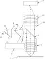
图1为本申请实施例所提供的一种可自动聚焦的荧光检测系统的结构示意图;FIG. 1 is a schematic structural diagram of an autofocusable fluorescence detection system provided by an embodiment of the application;
图2为本申请实施例所提供的一种自动聚焦方法的流程图;FIG. 2 is a flowchart of an automatic focusing method provided by an embodiment of the present application;
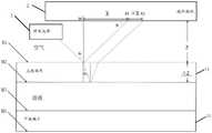
图3为本申请实施例中对焦光线在线阵相机和流动槽之间的光线传播模型示意图。FIG. 3 is a schematic diagram of the light propagation model of the focusing light between the line scan camera and the flow cell in the embodiment of the present application.
具体实施方式Detailed ways
为了使本技术领域的人员更好地理解本申请方案,下面结合附图和具体实施方式对本申请作进一步的详细说明。显然,所描述的实施例仅仅是本申请一部分实施例,而不是全部的实施例。基于本申请中的实施例,本领域普通技术人员在没有做出创造性劳动前提下所获得的所有其他实施例,都属于本申请保护的范围。In order to make those skilled in the art better understand the solution of the present application, the present application will be further described in detail below with reference to the accompanying drawings and specific embodiments. Obviously, the described embodiments are only a part of the embodiments of the present application, but not all of the embodiments. Based on the embodiments in the present application, all other embodiments obtained by those of ordinary skill in the art without creative efforts shall fall within the protection scope of the present application.
在下面的描述中阐述了很多具体细节以便于充分理解本发明,但是本发明还可以采用其他不同于在此描述的其它方式来实施,本领域技术人员可以在不违背本发明内涵的情况下做类似推广,因此本发明不受下面公开的具体实施例的限制。Many specific details are set forth in the following description to facilitate a full understanding of the present invention, but the present invention can also be implemented in other ways different from those described herein, and those skilled in the art can do so without departing from the connotation of the present invention. Similar promotion, therefore, the present invention is not limited by the specific embodiments disclosed below.
正如背景技术部分所述,目前荧光检测系统中进行自动聚焦所用的图像传感器为面阵相机,面阵相机是二维的,其中包括的像元总数较多,采集的数据量较大,即传输的数据量也较大,对硬件传输要求较高,对自动聚焦算法要求高,增加了算法的复杂性,增加了软件及硬件成本,并且,有效数据占比较小,导致自动聚焦速度较慢,进而使得荧光检测时效降低。As mentioned in the background art section, the image sensor used for auto-focusing in the current fluorescence detection system is an area array camera. The area array camera is two-dimensional, including a large number of pixels and a large amount of data collected, that is, the transmission of The data volume is also large, the hardware transmission requirements are high, and the autofocus algorithm requirements are high, which increases the complexity of the algorithm, and increases the software and hardware costs. In addition, the proportion of effective data is small, resulting in a slow autofocus speed. This further reduces the time-lapse of fluorescence detection.
有鉴于此,本申请提供了一种可自动聚焦的荧光检测系统,请参考图1,包括:In view of this, the present application provides an auto-focusing fluorescence detection system, please refer to Figure 1, including:
流动槽1,对焦组件,聚焦组件,线阵相机2,与所述线阵相机2连接的处理器,flow
所述流动槽1用于放置待测荧光物质;The
所述对焦组件用于发射对焦光线,所述对焦光线照射在所述流动槽1上并经过所述聚焦组件在所述线阵相机2上形成光斑图像;The focusing assembly is used for emitting focusing light, and the focusing light is irradiated on the
所述聚焦组件包括电机3和显微物镜4,所述电机3用于调整所述显微物镜4的位置以确定所述显微物镜4的焦平面;The focusing assembly includes a
所述处理器用于根据所述对焦光线在所述线阵相机2和所述流动槽1之间的光线传播模型、确定所述焦平面的位移、所述光斑图像确定所述显微物镜4的聚焦位移,并完成自动聚焦;The processor is configured to determine the displacement of the focal plane and the spot image according to the light propagation model of the focused light between the
其中,所述线阵相机2的长边与第一平面平行,所述第一平面为照射在所述流动槽1上的入射对焦光线和出射对焦光线形成的平面。The long side of the
流动槽1包括上下设置的上玻璃片、下玻璃片,上玻璃片和下玻璃片之间具有一定高度,比如300μm,且四周密封形成密封腔体,该腔体有进液管道与出液管道,待测荧光物质用溶剂包裹置于上玻璃片和下玻璃片之间的腔体中。The
所述对焦组件包括对焦光源5、孔径光阑6、第三二向色镜7、透镜8、第二二向色镜9,所述对焦光源5和所述第三二向色镜7分别位于所述孔径光阑6的两侧,所述透镜8和所述第二二向色镜9在远离所述第三二向色镜7的第二方向上依次分布,所述第二方向为所述对焦光线在所述第三二向色镜7反射后的方向。对焦光源5可以为LD(Laser Diode,激光二极管)光源。The focusing assembly includes a focusing
聚焦组件还包括第二滤光片10和短焦筒镜11,显微物镜4、第二滤光片10和短焦筒镜11在流动槽1和线阵相机2之间由下至上依次垂直分布。显微物镜4搭载在电机3上,电机3调整显微物镜4在垂直方向的位置,从而调整对焦光线在线阵相机2上形成的光斑图像的清晰度,当形成最清晰的光斑时,即确定出显微物镜4的焦平面。第二滤光片10只允许荧光透射。The focusing assembly also includes a
可选的,作为一种可实施方式,所述电机3为音圈电机3,但是本申请对此并不做具体限定,在其他实施方式中,电机3还可以为陶瓷电机3。Optionally, as an possible implementation manner, the
第二二向色镜9位于显微物镜4和第二滤光片10之间。The second
可自动聚焦的荧光检测系统还包括荧光激发组件,用于发射激发光激发待测荧光物质产生荧光。荧光激发组件包括第一光源12、第二光源13、第一二向色镜14、第一滤光片15、透镜8、第二二向色镜9,所述第一光源12和所述第二光源13分别设于所述第一二向色镜14的两侧,所述第一滤光片15、所述透镜8和所述第二二向色镜9在远离所述第一二向色镜14的第一方向上依次分布,所述第一方向为所述第一光源12和所述第二光源13的光线经过所述第一二向色镜14汇合传输的方向。The autofocusable fluorescence detection system further includes a fluorescence excitation component for emitting excitation light to excite the fluorescent substance to be detected to generate fluorescence. The fluorescence excitation assembly includes a
本申请中对第一光源12的类型不做限定,可自行设置。例如,所述第一光源12为LED(Light Emitting Diode,发光二极管)光源,或者第一光源12为LD(Laser Diode,激光二极管)光源。同理,本申请中对第二光源13的类型不做限定,可自行设置。例如,所述第二光源13为LED光源或者第二光源13为LD光源。当所述第一光源12和所述第二光源13为LED光源时,第一光源12可以为红光LED光源,第二光源13为绿光LED光源。The type of the
需要指出的是,本申请中对线阵相机2与控制器的连接方式不做具体限定。例如,所述处理器与所述线阵相机2通过有线连接方式连接,有线连接方式包括但不限于USB(Universal Serial Bus,通用串行总线)、HDMI(High Definition MultimediaInterface,高清多媒体接口)、专用的图像采集卡接口,或者处理器与所述线阵相机2通过无线连接方式连接,无线连接方式包括但不限于蓝牙、WiFi。It should be pointed out that the connection mode between the
可选的,在本申请的一个实施例中,所述线阵相机2为线阵CMOS(ComplementaryMetal Oxide Semiconductor,互补金属氧化物半导体)相机,但是本申请对此并不做具体限定,在本申请的其他实施例中,线阵相机2还可以为线阵CCD(Charge Coupled Device,电荷耦合器件)相机。线阵CMOS相机具有速度快、电路简单、成本低的特点。Optionally, in an embodiment of the present application, the
流动槽1(拍照的荧光靶面)形状的不同,线阵相机2的种类和安装方式也不同。例如,当流动槽1为长条形,线阵相机2为线阵CMOS相机,线阵相机2平面平行于流动槽1表面,线阵相机2的长边与流动槽1中待测荧光物质(荧光分子或者荧光基团)所在位置的长边在空间上相垂直。Depending on the shape of the flow cell 1 (the fluorescent target surface photographed), the type and installation method of the
下面结合图1对可自动聚焦的荧光检测系统中的光线传播过程进行阐述。The light propagation process in the autofocusable fluorescence detection system will be described below with reference to FIG. 1 .
第一光源12、第二光源13发出的光经过第一二向色镜14后,经过第一滤光片15、第三二向色镜7、透镜8聚光准直后,在第二二向色镜9的作用下改变光路方向经过显微物镜4聚焦后,照射到流动槽1中的待测荧光物质上激光荧光,激发的荧光经过显微物镜4、第二二向色镜9、第二滤光片10、短焦筒镜11进入线阵相机2。After the light emitted by the
对焦光源5发出的光经过孔径光阑6后照射到第三二向色镜7上,并在第三二向色镜7上改变传播方向,经过透镜8汇聚后照射在第二二向色镜9上,并在第二二向色镜9上改变传播方向经过显微物镜4以一定角度照射在流动槽1上。由于流动槽1包括上下分布的上玻璃片和下玻璃片,共有四个表面,分别为上玻璃片的上表面和下表面,下玻璃片的上表面和下表面,因此光线经过上玻璃片的上表面的上表面时一部分发生折射进入上玻璃片的内部,另一部分发生反射并通过显微物镜4、第二二向色镜9、短焦筒镜11在线阵相机2上成像,入射到上玻璃片内部的光线经过上玻璃片下表面、下玻璃片的上表面和下表面的光路与在上玻璃片上表面的光路一致,本申请不再详细赘述。The light emitted by the focusing
本申请检测系统中,对焦组件发射对焦光线照射至流动槽1上后在线阵相机2上形成光斑图像,电机3可以调整显微物镜4的位置确定出显微物镜4的焦平面,处理器可以根据对焦光线在线阵相机2和流动槽1之间的光线传播模型、确定焦平面时显微物镜4的位移以及光斑图像确定出显微物镜4需要聚焦的聚焦位移,进而根据聚焦位移调整显微物镜4的位置完成自动聚焦,由于光斑图像由线阵相机2采集得到,线阵相机2一维像元数可以做很多,且像元总数较面阵相机少,使得光斑图像采集速率提升,进而减少聚焦过程耗时,并且线阵相机2的长边与照射在流动槽1上的入射对焦光线和出射对焦光线形成的平面相平行,提升对焦光线在线阵相机2上成像的概率,提升聚焦速度,进而提升荧光检测效率;同时,线阵相机2传输至处理器的数据量少,因此对硬件传输要求降低,且对自动聚焦算法要求降低,简化自动聚焦算法,降低了数据传输的硬件成本及数据处理的软件成本。In the detection system of the present application, the focusing component emits focusing light and irradiates the
在上述任一实施例的基础上,在本申请的一个实施例中,所述第一平面与所述线阵相机2所在的第二平面相交于所述线阵相机2长边的中心线。On the basis of any of the above embodiments, in an embodiment of the present application, the first plane and the second plane where the
线阵相机2长边的中心线即,线阵相机2的长边有两条,中心线为两条长边中间位置的线,与长边平行。The center line of the long sides of the
本实施例中将照射在流动槽1上的入射对焦光线和出射对焦光线形成的平面与线阵相机2所在的第二平面相交的位置设置为线阵相机2长边的中心线,当改变流动槽1与显微物镜4之间的距离时,增加对焦光线在线阵相机2上成像的概率,进一步提升聚焦速度。In this embodiment, the position where the plane formed by the incident focusing light and the outgoing focusing light irradiated on the
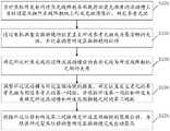
本申请还提供一种应用于上述任一实施例所述的可自动聚焦的荧光检测系统的自动聚焦方法,请参考图2,包括:The present application also provides an autofocusing method applied to the autofocusable fluorescence detection system described in any of the above embodiments, please refer to FIG. 2 , including:
步骤S101:当对焦组件发射的对焦光线照射在承载待测荧光物质的流动槽上并经过聚焦组件在线阵相机上形成光斑图像时,确定参考光斑。Step S101 : when the focusing light emitted by the focusing assembly is irradiated on the flow cell carrying the fluorescent substance to be tested and a spot image is formed on the line array camera through the focusing assembly, the reference spot is determined.
由于流动槽包括上下分布的上玻璃片和下玻璃片,光线在上玻璃片的上表面M1、下表面M2和下玻璃片的上表面M3、下表面M4均发生反射和折射,因此会在线阵相机上形成四个光斑,将上玻璃片11的上表面M1、下表面M2反射的光线形成的光斑分别为S1、S2如图3所示,下玻璃片的上表面M3、下表面M4反射的光线形成的光斑在S2的右侧依次分布。Since the flow cell includes an upper glass sheet and a lower glass sheet that are distributed up and down, the light is reflected and refracted on the upper surface M1, lower surface M2 of the upper glass sheet, and the upper surface M3 and lower surface M4 of the lower glass sheet, so the light will be reflected and refracted in the line array Four light spots are formed on the camera, and the light spots formed by the light reflected by the upper surface M1 and the lower surface M2 of the
本申请中对参考光斑不做限定,参考光斑可以为光斑S1或者S2。The reference light spot is not limited in this application, and the reference light spot may be the light spot S1 or S2.
步骤S102:通过电机调整显微物镜的位置直至所述参考光斑成为最清晰的光斑,并记录调整所述显微物镜的位移。Step S102 : adjust the position of the microscope objective lens by a motor until the reference light spot becomes the clearest light spot, and record and adjust the displacement of the microscope objective lens.
本步骤即通过电机调整显微物镜在垂直方向上的位置,确定出显微物镜的焦平面,记电机调整显微物镜的距离为Zbest。In this step, the position of the microscope objective lens in the vertical direction is adjusted by the motor to determine the focal plane of the microscope objective lens, and the distance of the microscope objective lens adjusted by the motor is recorded as Zbest .
步骤S103:确定所述对焦光线经过所述流动槽后的出射光线与所述线阵相机之间的夹角。Step S103: Determine the angle between the outgoing light after the focused light passes through the flow cell and the line scan camera.
为了简化自动聚焦方法的计算过程,设定参考光斑为对焦光线在上玻璃片的上表面发生反射后在所述线阵相机上形成的光斑,结合图3,所述确定所述对焦光线经过所述流动槽后的出射光线与所述线阵相机之间的夹角包括:In order to simplify the calculation process of the automatic focusing method, the reference light spot is set as the light spot formed on the line scan camera after the focusing light is reflected on the upper surface of the upper glass sheet. The angle between the outgoing light behind the flow cell and the line scan camera includes:
步骤S1031:根据所述上玻璃片的厚度、参考光斑与相邻的光斑的间距确定所述对焦光线在所述上玻璃片的折射角度。Step S1031: Determine the refraction angle of the focusing light on the upper glass sheet according to the thickness of the upper glass sheet and the distance between the reference light spot and the adjacent light spot.
上玻璃片的厚度是已知的,为△Z,参考光斑与相邻的光斑的间距为△X,则对焦光线在上玻璃片的折射角度θ2为:The thickness of the upper glass sheet is known, which is ΔZ, and the distance between the reference spot and the adjacent spot is ΔX, then the refraction angle θ2 of the focused light on the upper glass sheet is:
tanθ2=△X/2△Z (1)tanθ2 =△X/2△Z (1)
步骤S1032:根据所述折射角度和所述上玻璃片的折射率确定所述对焦光线在所述上玻璃片的入射角度。Step S1032: Determine the incident angle of the focused light on the upper glass sheet according to the refraction angle and the refractive index of the upper glass sheet.
上玻璃片的折射率n为:The refractive index n of the upper glass sheet is:
n=sinθ1/ sinθ2 (2)n=sinθ1 / sinθ2 (2)
上玻璃片为玻璃,折射率是已知的,从而根据公式(1)和(2)确定出对焦光线在上玻璃片的入射角度θ1。The upper glass sheet is glass, and the refractive index is known, so the incident angle θ1 of the focusing light on the upper glass sheet is determined according to formulas (1) and (2).
步骤S1033:所述入射角度的余角为所述夹角。Step S1033: The complementary angle of the incident angle is the included angle.
根据角度关系可知,夹角θ和入射角度θ1互余,因此可以得到夹角θ。According to the angle relationship, the included angle θ and the incident angle θ1 are complementary to each other, so the included angle θ can be obtained.
步骤S104:调整所述流动槽与所述显微物镜的距离,确定位置发生变化的参考光斑与预设参考点的第一间距,并根据所述第一间距和所述夹角确定所述流动槽和所述显微物镜之间的第二间距。Step S104: Adjust the distance between the flow cell and the microscope objective, determine the first distance between the reference spot whose position has changed and a preset reference point, and determine the flow according to the first distance and the included angle A second spacing between the groove and the microscope objective.
预设参考点S0为对焦光线在上玻璃片11的上表面M1发生反射时的法线与线阵相机2的交点。The preset reference point S0 is the intersection of the normal line when the focusing light is reflected on the upper surface M1 of the
当显微物镜的位置发生变化时,光斑的位置也会发生移动,设定位置发生变化的参考光斑与预设参考点的第一间距为X,可以测量得到,上玻璃片的上表面与线阵相机的距离为Z,则根据:When the position of the microscope objective changes, the position of the light spot will also move. The first distance between the reference light spot whose position has changed and the preset reference point is set to be X, which can be measured. The distance of the array camera is Z, then according to:
tanθ=Z/X (3)tanθ=Z/X (3)
可以得到上玻璃片的上表面与线阵相机的距离Z。The distance Z between the upper surface of the upper glass sheet and the line scan camera can be obtained.
步骤S105:根据所述位移和所述第二间距确定所述显微物镜的聚焦位移,并根据所述聚焦位移调整所述显微物镜完成自动聚焦。Step S105: Determine the focus displacement of the microscope objective lens according to the displacement and the second distance, and adjust the microscope objective lens according to the focus displacement to complete automatic focusing.
由于显微物镜的焦平面的距离Zbest是一定的,因此可以得到显微物镜的聚焦位移DZ为:Since the distance Zbest of the focal plane of the microscope objective is constant, the focus displacement DZ of the microscope objective can be obtained as:
DZ=Zbest-Z (4)DZ = Zbest -Z (4)
电机根据DZ调整显微物镜的位置,完成自动聚焦。The motor adjusts the position of the microscope objective lens according to DZ to complete automatic focusing.
本说明书中各个实施例采用递进的方式描述,每个实施例重点说明的都是与其它实施例的不同之处,各个实施例之间相同或相似部分互相参见即可。对于实施例公开的装置而言,由于其与实施例公开的方法相对应,所以描述的比较简单,相关之处参见方法部分说明即可。The various embodiments in this specification are described in a progressive manner, and each embodiment focuses on the differences from other embodiments, and the same or similar parts between the various embodiments may be referred to each other. As for the device disclosed in the embodiment, since it corresponds to the method disclosed in the embodiment, the description is relatively simple, and the relevant part can be referred to the description of the method.
以上对本申请所提供的可自动聚焦的荧光检测系统和自动聚焦方法进行了详细介绍。本文中应用了具体个例对本申请的原理及实施方式进行了阐述,以上实施例的说明只是用于帮助理解本申请的方法及其核心思想。应当指出,对于本技术领域的普通技术人员来说,在不脱离本申请原理的前提下,还可以对本申请进行若干改进和修饰,这些改进和修饰也落入本申请权利要求的保护范围内。The autofocusing fluorescence detection system and autofocusing method provided by the present application have been described in detail above. Specific examples are used herein to illustrate the principles and implementations of the present application, and the descriptions of the above embodiments are only used to help understand the methods and core ideas of the present application. It should be pointed out that for those of ordinary skill in the art, without departing from the principles of the present application, several improvements and modifications can also be made to the present application, and these improvements and modifications also fall within the protection scope of the claims of the present application.
Claims (10)
Translated fromChinesePriority Applications (1)
| Application Number | Priority Date | Filing Date | Title |
|---|---|---|---|
| CN202111645400.4ACN114858764B (en) | 2021-12-29 | 2021-12-29 | A fluorescence detection system capable of automatic focusing and an automatic focusing method |
Applications Claiming Priority (1)
| Application Number | Priority Date | Filing Date | Title |
|---|---|---|---|
| CN202111645400.4ACN114858764B (en) | 2021-12-29 | 2021-12-29 | A fluorescence detection system capable of automatic focusing and an automatic focusing method |
Publications (2)
| Publication Number | Publication Date |
|---|---|
| CN114858764Atrue CN114858764A (en) | 2022-08-05 |
| CN114858764B CN114858764B (en) | 2024-12-03 |
Family
ID=82627256
Family Applications (1)
| Application Number | Title | Priority Date | Filing Date |
|---|---|---|---|
| CN202111645400.4AActiveCN114858764B (en) | 2021-12-29 | 2021-12-29 | A fluorescence detection system capable of automatic focusing and an automatic focusing method |
Country Status (1)
| Country | Link |
|---|---|
| CN (1) | CN114858764B (en) |
Cited By (5)
| Publication number | Priority date | Publication date | Assignee | Title |
|---|---|---|---|---|
| CN115933152A (en)* | 2023-01-09 | 2023-04-07 | 深圳铭毅智造科技有限公司 | Real-time multi-surface automatic focusing system and focusing method |
| CN115951486A (en)* | 2023-01-09 | 2023-04-11 | 深圳铭毅智造科技有限公司 | Double-color fluorescence microscope system |
| CN116026806A (en)* | 2023-03-30 | 2023-04-28 | 山东德渡生物技术有限公司 | Fluorescence microscopy system |
| CN116754565A (en)* | 2023-08-04 | 2023-09-15 | 哈尔滨工业大学 | An automatic focus detection method for photofluorescence detection of micro-defects on the full-aperture surface of optical components |
| CN119845195A (en)* | 2025-03-20 | 2025-04-18 | 上海中科飞测半导体科技有限公司 | Axis deviation detection system and method for multi-magnification imaging system |
Citations (9)
| Publication number | Priority date | Publication date | Assignee | Title |
|---|---|---|---|---|
| JPH06265773A (en)* | 1993-02-02 | 1994-09-22 | Nec Corp | Autofocusing device for microscope |
| US6823079B1 (en)* | 1999-04-14 | 2004-11-23 | Carl Zeiss Jena Gmbh | Device for examining samples |
| JP2006309088A (en)* | 2005-05-02 | 2006-11-09 | Research Organization Of Information & Systems | Microscope focusing position high-precision measurement method |
| US20160041380A1 (en)* | 2014-08-06 | 2016-02-11 | Cellomics, Inc. | Image-based laser autofocus system |
| CN107621356A (en)* | 2017-10-31 | 2018-01-23 | 中国科学院苏州生物医学工程技术研究所 | A Microscope Focus Offset Measuring Equipment |
| CN111819485A (en)* | 2018-02-14 | 2020-10-23 | 国立研究开发法人理化学研究所 | Autofocus device, optical device and microscope having the same |
| CN112415735A (en)* | 2020-03-16 | 2021-02-26 | 中国科学院深圳先进技术研究院 | Real-time automatic focusing system for microscope |
| CN113640260A (en)* | 2021-07-27 | 2021-11-12 | 北京海维尔科技发展有限公司 | Gene sequencing method and gene sequencer |
| CN214953038U (en)* | 2021-04-12 | 2021-11-30 | 南方科技大学 | Super-resolution microscopic imaging system |
- 2021
- 2021-12-29CNCN202111645400.4Apatent/CN114858764B/enactiveActive
Patent Citations (10)
| Publication number | Priority date | Publication date | Assignee | Title |
|---|---|---|---|---|
| JPH06265773A (en)* | 1993-02-02 | 1994-09-22 | Nec Corp | Autofocusing device for microscope |
| US6823079B1 (en)* | 1999-04-14 | 2004-11-23 | Carl Zeiss Jena Gmbh | Device for examining samples |
| JP2006309088A (en)* | 2005-05-02 | 2006-11-09 | Research Organization Of Information & Systems | Microscope focusing position high-precision measurement method |
| US20160041380A1 (en)* | 2014-08-06 | 2016-02-11 | Cellomics, Inc. | Image-based laser autofocus system |
| CN205958834U (en)* | 2014-08-06 | 2017-02-15 | 赛洛米克斯股份有限公司 | Laser automatic focusing system based on image |
| CN107621356A (en)* | 2017-10-31 | 2018-01-23 | 中国科学院苏州生物医学工程技术研究所 | A Microscope Focus Offset Measuring Equipment |
| CN111819485A (en)* | 2018-02-14 | 2020-10-23 | 国立研究开发法人理化学研究所 | Autofocus device, optical device and microscope having the same |
| CN112415735A (en)* | 2020-03-16 | 2021-02-26 | 中国科学院深圳先进技术研究院 | Real-time automatic focusing system for microscope |
| CN214953038U (en)* | 2021-04-12 | 2021-11-30 | 南方科技大学 | Super-resolution microscopic imaging system |
| CN113640260A (en)* | 2021-07-27 | 2021-11-12 | 北京海维尔科技发展有限公司 | Gene sequencing method and gene sequencer |
Cited By (6)
| Publication number | Priority date | Publication date | Assignee | Title |
|---|---|---|---|---|
| CN115933152A (en)* | 2023-01-09 | 2023-04-07 | 深圳铭毅智造科技有限公司 | Real-time multi-surface automatic focusing system and focusing method |
| CN115951486A (en)* | 2023-01-09 | 2023-04-11 | 深圳铭毅智造科技有限公司 | Double-color fluorescence microscope system |
| CN116026806A (en)* | 2023-03-30 | 2023-04-28 | 山东德渡生物技术有限公司 | Fluorescence microscopy system |
| CN116754565A (en)* | 2023-08-04 | 2023-09-15 | 哈尔滨工业大学 | An automatic focus detection method for photofluorescence detection of micro-defects on the full-aperture surface of optical components |
| CN116754565B (en)* | 2023-08-04 | 2024-04-26 | 哈尔滨工业大学 | Automatic focusing detection method for optical element full-caliber surface micro-defect photo-induced fluorescence detection |
| CN119845195A (en)* | 2025-03-20 | 2025-04-18 | 上海中科飞测半导体科技有限公司 | Axis deviation detection system and method for multi-magnification imaging system |
Also Published As
| Publication number | Publication date |
|---|---|
| CN114858764B (en) | 2024-12-03 |
Similar Documents
| Publication | Publication Date | Title |
|---|---|---|
| CN114858764B (en) | A fluorescence detection system capable of automatic focusing and an automatic focusing method | |
| US8599372B2 (en) | Linear chromatic confocal microscopic system | |
| WO2021159285A1 (en) | Optical imaging system and biochemical substance detection system using same | |
| CN104316506B (en) | Raman probe and Raman signal detection system and method capable of focusing automatically | |
| CN101467087A (en) | Method and apparatus for auto-focussing infinity corrected microscopes | |
| JP2018151624A5 (en) | ||
| JP6729960B2 (en) | Camera module adjusting device and camera module adjusting method | |
| AU2018287064A1 (en) | Method and microscopy system for recording an image | |
| KR101704859B1 (en) | Focus distance measurement method and apparatus of microlens | |
| WO2024146533A1 (en) | Focusing method, optical imaging system, sequencing system, and medium | |
| CN112748564A (en) | Microscope device and focusing method thereof | |
| JP2018017970A (en) | Optical sheet microscope and method for controlling optical sheet microscope | |
| CN115452784B (en) | Automatic focusing system, gene sequencing system and automatic focusing method | |
| CN114858762B (en) | Imaging device focusing method and imaging system | |
| US20250076627A1 (en) | Imaging system, sequencing system, and imaging method | |
| CN1790092A (en) | High precision light beam coaxiality adjusting method | |
| KR20150114199A (en) | Defect inspecting apparatus for ir filter with automatic focus control unit | |
| JP5070995B2 (en) | Confocal microscope | |
| CN116540393B (en) | Autofocus system and method, semiconductor defect detection system and method | |
| WO2024183011A1 (en) | Focusing method and system | |
| CN213337349U (en) | Micro-droplet double-fluorescence signal detection device | |
| CN220650468U (en) | Optical imaging device and gene sequencing equipment | |
| CN113776784A (en) | Lens Test System | |
| KR101707990B1 (en) | auto focusing apparatus using slitbeam and auto focusing method using thereof | |
| CN117991488A (en) | Imaging system, sequencing system and imaging method |
Legal Events
| Date | Code | Title | Description |
|---|---|---|---|
| PB01 | Publication | ||
| PB01 | Publication | ||
| SE01 | Entry into force of request for substantive examination | ||
| SE01 | Entry into force of request for substantive examination | ||
| GR01 | Patent grant | ||
| GR01 | Patent grant |