CN114852877A - Novel template trolley - Google Patents
Novel template trolleyDownload PDFInfo
- Publication number
- CN114852877A CN114852877ACN202210477943.8ACN202210477943ACN114852877ACN 114852877 ACN114852877 ACN 114852877ACN 202210477943 ACN202210477943 ACN 202210477943ACN 114852877 ACN114852877 ACN 114852877A
- Authority
- CN
- China
- Prior art keywords
- fixed
- transverse beam
- main
- trolley
- transverse
- Prior art date
- Legal status (The legal status is an assumption and is not a legal conclusion. Google has not performed a legal analysis and makes no representation as to the accuracy of the status listed.)
- Granted
Links
- 238000009415formworkMethods0.000claimsabstractdescription19
- 230000001681protective effectEffects0.000claimsdescription7
- 229920001343polytetrafluoroethylenePolymers0.000claimsdescription5
- 239000004810polytetrafluoroethyleneSubstances0.000claimsdescription5
- -1polytetrafluoroethylenePolymers0.000claimsdescription3
- 230000000149penetrating effectEffects0.000claimsdescription2
- 238000009434installationMethods0.000abstractdescription15
- 230000000694effectsEffects0.000abstractdescription5
- 229910000831SteelInorganic materials0.000description8
- 239000010959steelSubstances0.000description8
- 238000010586diagramMethods0.000description5
- 238000004519manufacturing processMethods0.000description2
- 238000000034methodMethods0.000description2
- 239000004809TeflonSubstances0.000description1
- 229920006362Teflon®Polymers0.000description1
- 238000010276constructionMethods0.000description1
- 230000007812deficiencyEffects0.000description1
- 238000012986modificationMethods0.000description1
- 230000004048modificationEffects0.000description1
- 238000003825pressingMethods0.000description1
- 239000007787solidSubstances0.000description1
- BFKJFAAPBSQJPD-UHFFFAOYSA-NtetrafluoroetheneChemical groupFC(F)=C(F)FBFKJFAAPBSQJPD-UHFFFAOYSA-N0.000description1
- 238000003466weldingMethods0.000description1
Images


Classifications
- B—PERFORMING OPERATIONS; TRANSPORTING
- B66—HOISTING; LIFTING; HAULING
- B66C—CRANES; LOAD-ENGAGING ELEMENTS OR DEVICES FOR CRANES, CAPSTANS, WINCHES, OR TACKLES
- B66C19/00—Cranes comprising trolleys or crabs running on fixed or movable bridges or gantries
- B—PERFORMING OPERATIONS; TRANSPORTING
- B66—HOISTING; LIFTING; HAULING
- B66C—CRANES; LOAD-ENGAGING ELEMENTS OR DEVICES FOR CRANES, CAPSTANS, WINCHES, OR TACKLES
- B66C6/00—Girders, or track-supporting structures, specially adapted for cranes
- B—PERFORMING OPERATIONS; TRANSPORTING
- B66—HOISTING; LIFTING; HAULING
- B66C—CRANES; LOAD-ENGAGING ELEMENTS OR DEVICES FOR CRANES, CAPSTANS, WINCHES, OR TACKLES
- B66C9/00—Travelling gear incorporated in or fitted to trolleys or cranes
- B66C9/08—Runners; Runner bearings
- B—PERFORMING OPERATIONS; TRANSPORTING
- B66—HOISTING; LIFTING; HAULING
- B66C—CRANES; LOAD-ENGAGING ELEMENTS OR DEVICES FOR CRANES, CAPSTANS, WINCHES, OR TACKLES
- B66C9/00—Travelling gear incorporated in or fitted to trolleys or cranes
- B66C9/14—Trolley or crane travel drives
- B—PERFORMING OPERATIONS; TRANSPORTING
- B66—HOISTING; LIFTING; HAULING
- B66F—HOISTING, LIFTING, HAULING OR PUSHING, NOT OTHERWISE PROVIDED FOR, e.g. DEVICES WHICH APPLY A LIFTING OR PUSHING FORCE DIRECTLY TO THE SURFACE OF A LOAD
- B66F11/00—Lifting devices specially adapted for particular uses not otherwise provided for
- B66F11/04—Lifting devices specially adapted for particular uses not otherwise provided for for movable platforms or cabins, e.g. on vehicles, permitting workmen to place themselves in any desired position for carrying out required operations
- E—FIXED CONSTRUCTIONS
- E01—CONSTRUCTION OF ROADS, RAILWAYS, OR BRIDGES
- E01D—CONSTRUCTION OF BRIDGES, ELEVATED ROADWAYS OR VIADUCTS; ASSEMBLY OF BRIDGES
- E01D21/00—Methods or apparatus specially adapted for erecting or assembling bridges
Landscapes
- Engineering & Computer Science (AREA)
- Mechanical Engineering (AREA)
- Structural Engineering (AREA)
- Architecture (AREA)
- Civil Engineering (AREA)
- Life Sciences & Earth Sciences (AREA)
- Geology (AREA)
- Carriers, Traveling Bodies, And Overhead Traveling Cranes (AREA)
Abstract
Translated fromChinese
Description
Translated fromChinese技术领域:Technical field:
本发明涉及起重设备技术领域,更具体的说涉及一种新型模板小车。The invention relates to the technical field of lifting equipment, and more particularly to a novel formwork trolley.
背景技术:Background technique:
现有的架桥建造过程中,其需要在桥体的侧面墙体上安装模板和拆除悬臂撑杆作用,现有的拆卸安装是在需要拆装位置处安装架体,人随着架体爬到桥体的侧面处进行模板安装和悬臂撑杆的拆卸,其效果差,效率低,而且拆完或安装一处后,将架体人工移动到另一个工位,非常麻烦。During the construction of the existing bridge, it is necessary to install the template on the side wall of the bridge body and remove the cantilever strut. The installation of the formwork and the disassembly of the cantilever strut at the side of the bridge body have poor effect and low efficiency, and it is very troublesome to manually move the frame body to another station after dismantling or installing one place.
发明内容:Invention content:
本发明的目的是克服现有技术的不足,提供一种新型模板小车,它可以沿着桥面移动,其可以将操作人员移动至桥体侧壁处,同时可以起吊模板等工具,方便模板安装和悬臂撑杆的拆卸,其效果好,效率高。The purpose of the present invention is to overcome the deficiencies of the prior art and provide a new formwork trolley, which can move along the bridge deck, can move the operator to the side wall of the bridge body, and can lift tools such as formwork at the same time to facilitate the installation of the formwork And the disassembly of the cantilever strut has good effect and high efficiency.
本发明解决所述技术问题的方案是:The solution of the present invention to solve the technical problem is:
一种新型模板小车,包括放置在桥架顶面的小车底架,所述小车底架的前端和后部的顶面固定有多个前后对应的竖直支撑柱,前后延伸的主横向梁固定在前后对应的两个竖直支撑柱的顶面上,主横向梁的前部伸出前端的竖直支撑柱;A new type of formwork trolley includes a trolley underframe placed on the top surface of a bridge frame, a plurality of front and rear corresponding vertical support columns are fixed on the front and rear top surfaces of the trolley underframe, and a main transverse beam extending front and rear is fixed on the top surface. On the top surfaces of the two vertical support columns corresponding to the front and rear, the front part of the main transverse beam protrudes from the vertical support column at the front end;
所述主横向梁的中部成型有上下贯穿的横向通槽,主横向梁的底面固定有前后延伸的横向齿条,移动壳体插套在主横向梁上,移动壳体的中部安装有主竖直连接臂,主竖直连接臂的上部插套在对应的横向通槽中,主竖直连接臂的顶部伸出移动壳体的顶面,左右对应的两个主竖直连接臂的顶部之间设有移动横向梁,移动横向梁固定在对应的两个移动壳体的顶面上,移动壳体的下部外侧壁上固定有移动驱动电机,移动驱动电机的输出轴的外侧壁上成型有外齿部,外齿部与对应的横向齿条相啮合;The middle part of the main transverse beam is formed with a transverse through groove that penetrates up and down, the bottom surface of the main transverse beam is fixed with a transverse rack extending forward and backward, the mobile casing is inserted and sleeved on the main transverse beam, and the main vertical beam is installed in the middle of the mobile casing. The straight connecting arm, the upper part of the main vertical connecting arm is inserted into the corresponding transverse through groove, the top of the main vertical connecting arm protrudes from the top surface of the mobile housing, and the top of the two corresponding left and right main vertical connecting arms is between the tops. There are moving transverse beams between them, and the moving transverse beams are fixed on the top surfaces of the corresponding two mobile casings. The mobile driving motor is fixed on the lower outer side wall of the mobile casing, and the outer side wall of the output shaft of the mobile driving motor is formed with External teeth, which mesh with corresponding transverse racks;
所述主竖直连接臂的中部成型有竖直矩形通孔,升降杆的上部插套在主竖直连接臂的矩形通孔中,升降杆与竖直矩形通孔相配合;The middle part of the main vertical connecting arm is formed with a vertical rectangular through hole, the upper part of the lifting rod is inserted into the rectangular through hole of the main vertical connecting arm, and the lifting rod is matched with the vertical rectangular through hole;
所有的升降杆的底端固定在同一个安装平台的顶面上,安装平台处于桥架的前方,安装平台的前端顶面固定有上防护栏杆架,移动横向梁上安装有第一电动环链葫芦,所有第一电动环链葫芦的挂钩挂在上防护栏杆架上。The bottom ends of all lifting rods are fixed on the top surface of the same installation platform, the installation platform is in front of the bridge, the front end of the installation platform is fixed with the upper protective railing frame, and the first electric chain hoist is installed on the moving transverse beam , all the hooks of the first electric chain hoist are hung on the upper protective railing frame.
所述小车底架的后端安装有配重块,配重块处于后方的竖直支撑柱的后方。A counterweight block is installed at the rear end of the trolley chassis, and the counterweight block is located behind the rear vertical support column.
所述主横向梁上插套有第二移动壳体,相邻的两个第二移动壳体之间设有第二移动横向梁,第二移动横向梁的端部固定在对应的第二移动壳体的顶面上,第二移动横向梁上安装有第二电动环链葫芦。A second movable casing is inserted and sleeved on the main transverse beam, a second movable transverse beam is arranged between two adjacent second movable casings, and the end of the second movable transverse beam is fixed on the corresponding second movable casing. On the top surface of the casing, a second electric chain hoist is installed on the second moving transverse beam.
所述第二移动横向梁处于移动横向梁的后方。The second moving transverse beam is behind the moving transverse beam.
所述主横向梁的顶面固定有聚四氟乙烯板,移动壳体和第二移动壳体的左右两个侧板的内侧壁上均固定有导向板,导向板的底面紧贴对应的聚四氟乙烯板的顶面上。A polytetrafluoroethylene plate is fixed on the top surface of the main transverse beam, guide plates are fixed on the inner side walls of the left and right side plates of the mobile casing and the second mobile casing, and the bottom surfaces of the guide plates are in close contact with the corresponding polytetrafluoroethylene plates. on the top surface of the tetrafluoroethylene plate.
所述小车底架为框型架,小车底架的前后两个侧梁的底面的左部均固定有后车轮架,后车轮架上通过铰接轴活动连接有后车轮,后车轮架的侧壁上固定有减速电机,减速电机带动对应的后车轮转动。The underframe of the trolley is a frame frame, and the left part of the bottom surface of the front and rear side beams of the trolley is fixed with a rear wheel frame, and the rear wheel frame is movably connected with a rear wheel through a hinge shaft. A deceleration motor is fixed on the top, and the deceleration motor drives the corresponding rear wheel to rotate.
所述小车底架的前后两个侧梁的右部均通过竖直转轴铰接有前车轮架,前车轮架中通过轴承活动连接有前车轮;The right parts of the front and rear side beams of the trolley chassis are both hinged with a front wheel frame through a vertical rotating shaft, and the front wheel frame is movably connected with a front wheel through a bearing;
所述前车轮架的左侧固定或成型有连接部,前后延伸的转向连接杆的两端通过铰接轴活动连接在两个对应的前车轮架的连接部上;A connecting portion is fixed or formed on the left side of the front wheel frame, and both ends of the steering connecting rod extending front and rear are movably connected to the connecting portions of the two corresponding front wheel frames through a hinge shaft;
所述小车底架的前后两个侧梁的右端之间设有中部连接梁,中部连接梁的端部固定在对应的侧梁的右部内侧壁上;A middle connecting beam is arranged between the right ends of the front and rear side beams of the trolley underframe, and the ends of the middle connecting beam are fixed on the right inner wall of the corresponding side beam;
所述中部连接梁的中部固定有转向连接座,旋转连接座上通过铰接轴活动连接有电动推杆,其中一个前车轮架的右端固定有转向连接部,电动推杆的推杆端部通过铰接轴活动连接在转向连接部上。A steering connection seat is fixed in the middle of the middle connecting beam, and an electric push rod is movably connected to the rotary connection seat through a hinge shaft. The right end of one of the front wheel frames is fixed with a steering connection part, and the push rod end of the electric push rod is hinged The shaft is movably connected to the steering connection.
本发明的突出效果是:The outstanding effect of the present invention is:
与现有技术相比,它可以沿着桥面移动,其可以将操作人员移动至桥体侧壁处,同时可以起吊模板等工具,方便模板安装和悬臂撑杆的拆卸,其效果好,效率高。Compared with the prior art, it can move along the bridge deck, it can move the operator to the side wall of the bridge body, and at the same time, it can lift tools such as formwork, which is convenient for the installation of the formwork and the disassembly of the cantilever strut, with good effect and high efficiency. high.
附图说明:Description of drawings:
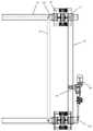
图1是本发明的结构示意图;Fig. 1 is the structural representation of the present invention;
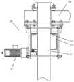
图2是本发明的第二移动壳体处的局部结构示意图;Fig. 2 is the partial structure schematic diagram of the second mobile casing of the present invention;
图3是本发明的安装平台处的局部结构示意图;Fig. 3 is the partial structure schematic diagram of the installation platform of the present invention;
图4是电动推杆处的局部结构示意图;Fig. 4 is the partial structure schematic diagram of electric push rod place;
图5是第二移动壳体与主横向梁的局部结构示意图;Fig. 5 is the partial structure schematic diagram of the second mobile shell and the main transverse beam;
图6是移动壳体与主横向梁的局部结构示意图。Fig. 6 is a partial structural schematic diagram of the moving shell and the main transverse beam.
具体实施方式:Detailed ways:
实施例,见如图1至图6所示,一种新型模板小车,包括放置在桥架100顶面的两个小车底架10拼装组成的移动小车架,所述小车底架10为矩形框型架,所述小车底架10的前端和后部的顶面的左部和右部分别固定有四个前后对应的竖直支撑柱11,前后延伸的主横向梁12固定在前后对应的两个竖直支撑柱11的顶面上,主横向梁12的前部伸出前端的竖直支撑柱11;两个小车底架10的相靠近一侧固定连接。两个小车底架10的相靠近的两个竖直支撑柱11之间通过侧连接块相固定。In an embodiment, as shown in FIGS. 1 to 6 , a new type of template trolley includes a mobile trolley formed by assembling two
所述主横向梁12由两个槽型钢123和两个端部板124组成,两个槽型钢123的同一侧的端部之间设有端部板124,端部板124的侧壁焊接固定在对应的槽型钢123的内侧壁上,两个槽型钢123之间成型有上下贯穿的横向通槽121,主横向梁12的其中一个槽型钢123的底面固定有前后延伸的横向齿条122,移动壳体20和第二移动壳体50插套在主横向梁12上;The main
所述移动壳体20和第二移动壳体50均包括左右两个侧固定板201,两个侧固定板201处于主横向梁12的左右两侧处,两个侧固定板201的顶端固定有上部连接板;两个侧固定板201的上部和下部之间均设有多个双头螺杆,双头螺杆的两端螺接部伸出对应的侧固定板201并螺接有两个相互压靠的螺母,内侧处的螺母压靠在侧固定板201的外侧壁,主横向梁12处于上方的双头螺杆和下方的双头螺杆之间;The moving
小车底架10的左右两个移动壳体20的上部之间设有移动横向梁30,移动横向梁30的左右两端底面通过螺栓固定连接在移动壳体20的上部连接板上;小车底架10的左右两个第二移动壳体50的上部之间设有第二移动横向梁52,第二移动横向梁52的左右两端底面通过螺栓固定连接在第二移动壳体50的上部连接板上;两个第二移动横向梁52相靠近端通过连接块相连接固定。A moving
移动壳体20的中部安装有主竖直连接臂21,主竖直连接臂21的上部处于两个侧固定板201之间,其插套在对应的主横向梁12的横向通槽121中,主竖直连接臂21的顶部伸出移动壳体20的顶面,主竖直连接臂21的顶部侧壁上固定有连接座,连接座通过螺栓固定连接在对应的移动横向梁30上,移动壳体20和第二移动壳体50的其中一个侧固定板201的外侧壁的下部均固定有移动驱动电机22,移动驱动电机22的输出轴的外侧壁上成型有外齿部,外齿部与对应的横向齿条122相啮合;A main
所述主竖直连接臂21的中部成型有竖直矩形通孔,升降杆23的上部插套在主竖直连接臂21的矩形通孔中,升降杆23与竖直矩形通孔相配合;A vertical rectangular through hole is formed in the middle of the main vertical connecting
所有的升降杆23的底端固定在同一个安装平台40的顶面上,安装平台40处于桥架100的前方,安装平台40的前端顶面固定有上防护栏杆架41,移动横向梁30上安装有第一电动环链葫芦1,所有第一电动环链葫芦1的挂钩挂在上防护栏杆架41上(附图中其第一电动环链葫芦1的挂钩未挂在上防护栏杆架41上)。The bottom ends of all
所述小车底架10的后端安装有配重块2,配重块2处于后方的竖直支撑柱11的后方。A counterweight block 2 is installed at the rear end of the
第二移动横向梁52上安装有第二电动环链葫芦3。The second electric chain hoist 3 is mounted on the second moving
进一步的说,所述第二移动横向梁50处于移动横向梁30的后方。Further, the second moving
所述主横向梁12的两个槽型钢123的顶面均固定有聚四氟乙烯板4,移动壳体20和第二移动壳体50的左右两个侧固定板201的内侧壁上均固定有横向延伸的导向板5,导向板5的底面紧贴对应的聚四氟乙烯板4的顶面上。主横向梁12的中部左右两侧壁面上固定限位板对移动壳体20或第二移动壳体50向后移动实现限位。Teflon plates 4 are fixed on the top surfaces of the two
两个小车底架10的前后两个侧梁的底面的左部均固定有后车轮架13,后车轮架13上通过铰接轴活动连接有后车轮14,后车轮架13的侧壁上固定有减速电机15,后车轮14的铰接轴中部固定在后车轮14上,后车轮14的铰接轴通过轴承活动连接在后车轮架13上,后车轮14的铰接轴的一端插入减速电机15的动力输出孔中并通过键连接固定,减速电机15带动对应的后车轮14转动运行,实现移动。The left parts of the bottom surfaces of the front and rear side beams of the two
进一步的说,所述小车底架10的前后两个侧梁的右部均通过竖直转轴铰接有前车轮架16,前车轮架16中通过轴承活动连接有前车轮17;Further, the
所述前车轮架16的左侧固定或成型有连接部161,前后延伸的转向连接杆18的两端通过铰接轴活动连接在两个对应的前车轮架16的连接部161上;A connecting
所述小车底架10的前后两个侧梁的右端之间设有中部连接梁19,中部连接梁19的端部固定在对应的侧梁的右部内侧壁上;A middle connecting
所述中部连接梁19的中部固定有转向连接座191,旋转连接座191上通过铰接轴活动连接有电动推杆60,其中一个前车轮架16的右端固定有转向连接部162,电动推杆60的推杆端部通过铰接轴活动连接在转向连接部162上。A
所述前后对应的两个竖直支撑柱11之间设有十字交叉固定的中间支撑架80,中间支撑架80的前部两端固定在前部的竖直支撑柱11上,中间支撑架80的后部两端固定在后部的竖直支撑柱11上。A
本实施例中的前车轮17和后车轮14均为橡胶实心轮胎。The
小车底架10上还固定有控制主机,控制主机中安装有控制器、蓄电池等装置,为本实施例提供电源,其为常用结构,不再详述。A control host is also fixed on the
每个小车底架10处的两个主横向梁12的前部之间设有固定支撑梁,固定支撑梁的两端固定在对应的两个主横向梁12的前部侧壁上。A fixed support beam is provided between the front parts of the two main
工作原理:本实施例在使用时,其放置在桥架100的边部顶面上,其通过减速电机15运行,可以实现移动小车架移动,其通过右侧的小车底架10处的电动推杆60运行,可以实现对应的两个前车轮17转向,其转动角度为±35度,从而可以实现移动小车架的位置移动;Working principle: When this embodiment is in use, it is placed on the top surface of the side of the
当两个小车底架10分离时,其通过每个小车底架10处的电动推杆60运行,实现单独控制其转向。When the two trolley bottom frames 10 are separated, they run through the
本实施例中,在使用时,其第二电动环链葫芦3上可以起吊模板等装置,而操作人员处于安装平台40上,通过对应的移动驱动电机22运行,使得移动驱动电机22的输出轴沿着横向齿条122旋转移动,实现移动壳体20和第二移动壳体50可以沿着主横向梁12进行前后移动,使得移动横向梁30和第二移动横向梁52可以沿着主横向梁12进行前后移动,实现安装平台40和起吊的模板进行前后移动;In this embodiment, when in use, the second electric chain hoist 3 can hoist the formwork and other devices, while the operator is on the
同时,通过第一电动环链葫芦1的吊钩的升降拉动,可以实现升降杆23沿着主竖直连接臂21进行上下升降,实现安装平台40的高低调节,使得其上的操作人员可以进行升降满足使用的需要;At the same time, through the lifting and pulling of the hook of the first electric chain hoist 1, the lifting
所述安装平台40的左右两侧顶面均固定有侧防护网板。The top surfaces of the left and right sides of the
本实施例中,其采用移动驱动电机22的输出轴沿着横向齿条122旋转移动,从而实现对应的移动壳体20和第二移动壳体50可以沿着主横向梁12进行前后移动,其移动结构简单,制造方便,大大降低制造成本。In this embodiment, the output shaft of the
本实施例中的主横向梁12由两个槽型钢123和两个端部板124组成,两个槽型钢123的同一端的端面焊接固定在对应的端部板124上,两个槽型钢123之间成型有上下贯穿的横向通槽121,其加工方便,横向通槽121无需采用机加工切割制成,而是通过焊接拼装后组成横向通槽121,从而大大降低加工难度和加工成本。The main
最后,以上实施方式仅用于说明本发明,而并非对本发明的限制,有关技术领域的普通技术人员,在不脱离本发明的精神和范围的情况下,还可以做出各种变化和变型,因此所有等同的技术方案也属于本发明的范畴,本发明的专利保护范围应由权利要求限定。Finally, the above embodiments are only used to illustrate the present invention, but not to limit the present invention. Those of ordinary skill in the relevant technical field can also make various changes and modifications without departing from the spirit and scope of the present invention. Therefore, all equivalent technical solutions also belong to the scope of the present invention, and the patent protection scope of the present invention should be defined by the claims.
Claims (7)
Translated fromChinesePriority Applications (1)
| Application Number | Priority Date | Filing Date | Title |
|---|---|---|---|
| CN202210477943.8ACN114852877B (en) | 2022-05-05 | 2022-05-05 | A template trolley |
Applications Claiming Priority (1)
| Application Number | Priority Date | Filing Date | Title |
|---|---|---|---|
| CN202210477943.8ACN114852877B (en) | 2022-05-05 | 2022-05-05 | A template trolley |
Publications (2)
| Publication Number | Publication Date |
|---|---|
| CN114852877Atrue CN114852877A (en) | 2022-08-05 |
| CN114852877B CN114852877B (en) | 2025-02-14 |
Family
ID=82634961
Family Applications (1)
| Application Number | Title | Priority Date | Filing Date |
|---|---|---|---|
| CN202210477943.8AActiveCN114852877B (en) | 2022-05-05 | 2022-05-05 | A template trolley |
Country Status (1)
| Country | Link |
|---|---|
| CN (1) | CN114852877B (en) |
Citations (5)
| Publication number | Priority date | Publication date | Assignee | Title |
|---|---|---|---|---|
| JP2000264576A (en)* | 1999-03-18 | 2000-09-26 | Ishikawajima Harima Heavy Ind Co Ltd | Trolley traversing device |
| JP2007112526A (en)* | 2005-10-18 | 2007-05-10 | Tooa Eito Kk | Self-traveling type small sized crane |
| CN211496667U (en)* | 2019-12-19 | 2020-09-15 | 纽科伦(新乡)起重机有限公司 | Gantry crane with liftable girder |
| CN113250095A (en)* | 2021-06-24 | 2021-08-13 | 浙江中建路桥设备有限公司 | Pier roof beam integration is built with machine of putting up bridge |
| CN114408819A (en)* | 2022-01-05 | 2022-04-29 | 腾盛桥工科技(重庆)有限公司 | High-altitude edge-facing multifunctional operation platform |
- 2022
- 2022-05-05CNCN202210477943.8Apatent/CN114852877B/enactiveActive
Patent Citations (5)
| Publication number | Priority date | Publication date | Assignee | Title |
|---|---|---|---|---|
| JP2000264576A (en)* | 1999-03-18 | 2000-09-26 | Ishikawajima Harima Heavy Ind Co Ltd | Trolley traversing device |
| JP2007112526A (en)* | 2005-10-18 | 2007-05-10 | Tooa Eito Kk | Self-traveling type small sized crane |
| CN211496667U (en)* | 2019-12-19 | 2020-09-15 | 纽科伦(新乡)起重机有限公司 | Gantry crane with liftable girder |
| CN113250095A (en)* | 2021-06-24 | 2021-08-13 | 浙江中建路桥设备有限公司 | Pier roof beam integration is built with machine of putting up bridge |
| CN114408819A (en)* | 2022-01-05 | 2022-04-29 | 腾盛桥工科技(重庆)有限公司 | High-altitude edge-facing multifunctional operation platform |
Non-Patent Citations (1)
| Title |
|---|
| 张战前;: "新型自动倾翻钢包小车结构设计", 内燃机与配件, no. 12, 30 June 2020 (2020-06-30)* |
Also Published As
| Publication number | Publication date |
|---|---|
| CN114852877B (en) | 2025-02-14 |
Similar Documents
| Publication | Publication Date | Title |
|---|---|---|
| CN209143545U (en) | Boom hoisting is used in ventilation shaft installation | |
| CN111438476A (en) | Frame type frame clamping mechanism capable of automatically overturning and used for welding | |
| CN114852877A (en) | Novel template trolley | |
| CN115043329A (en) | Industrial equipment installs with removing booster unit | |
| CN201165463Y (en) | The Vertical Lifting and Moving Mechanism of Large Diameter Cylindrical Vacuum Bell Jar | |
| CN218976148U (en) | Electric power overhauls work rack | |
| CN216471896U (en) | Novel balance crane | |
| CN115786649A (en) | A trolley wheel disassembly tooling and disassembly and installation method | |
| CN212665331U (en) | A longitudinal beam assembly inversion welding device | |
| CN212249079U (en) | House building construction platform | |
| CN211058337U (en) | Lifting construction mechanical equipment | |
| CN217297043U (en) | Novel hoisting of template dolly device | |
| CN213197614U (en) | Robot maintenance platform convenient to dismouting | |
| CN213008235U (en) | Movable fixing frame | |
| CN223188371U (en) | A motor turning device | |
| CN218968773U (en) | A mechanical arm auxiliary disassembly device | |
| CN220741039U (en) | Aluminum door and window assembly lifting platform convenient to move | |
| CN221696927U (en) | Multipurpose power-assisted mechanical arm | |
| CN220317162U (en) | Safety maintenance device for electric hoist gantry crane | |
| CN111673326A (en) | An intelligent welding equipment for automobile frame | |
| CN223131065U (en) | Supporting device for stone cutting machine | |
| CN218612686U (en) | Motor reducer replacing device | |
| CN218905455U (en) | Gantry reverse-hanging type robot | |
| CN117139826B (en) | Chemical laser repair processing platform and laser repair equipment | |
| CN220607750U (en) | Double-sided reversible working platform |
Legal Events
| Date | Code | Title | Description |
|---|---|---|---|
| PB01 | Publication | ||
| PB01 | Publication | ||
| SE01 | Entry into force of request for substantive examination | ||
| SE01 | Entry into force of request for substantive examination | ||
| GR01 | Patent grant | ||
| GR01 | Patent grant |