CN114849017A - Controllable bent catheter and control handle thereof - Google Patents
Controllable bent catheter and control handle thereofDownload PDFInfo
- Publication number
- CN114849017A CN114849017ACN202210647878.9ACN202210647878ACN114849017ACN 114849017 ACN114849017 ACN 114849017ACN 202210647878 ACN202210647878 ACN 202210647878ACN 114849017 ACN114849017 ACN 114849017A
- Authority
- CN
- China
- Prior art keywords
- wire
- cover
- proximal
- handle
- controllable
- Prior art date
- Legal status (The legal status is an assumption and is not a legal conclusion. Google has not performed a legal analysis and makes no representation as to the accuracy of the status listed.)
- Pending
Links
- 230000002439hemostatic effectEffects0.000claimsabstractdescription13
- 238000005491wire drawingMethods0.000claimsabstractdescription13
- 229910045601alloyInorganic materials0.000claimsdescription16
- 239000000956alloySubstances0.000claimsdescription16
- 230000000903blocking effectEffects0.000claimsdescription13
- 229910052751metalInorganic materials0.000claimsdescription12
- 239000002184metalSubstances0.000claimsdescription12
- 229920000642polymerPolymers0.000claimsdescription12
- 230000001681protective effectEffects0.000claimsdescription12
- 239000003292glueSubstances0.000claimsdescription6
- 230000003014reinforcing effectEffects0.000claimsdescription6
- 238000002347injectionMethods0.000claimsdescription5
- 239000007924injectionSubstances0.000claimsdescription5
- 230000002787reinforcementEffects0.000claimsdescription5
- 239000000853adhesiveSubstances0.000claims1
- 230000001070adhesive effectEffects0.000claims1
- 238000005452bendingMethods0.000abstractdescription19
- 230000002457bidirectional effectEffects0.000abstractdescription10
- 238000004519manufacturing processMethods0.000abstractdescription6
- 230000005540biological transmissionEffects0.000abstractdescription3
- 239000010410layerSubstances0.000description21
- 239000002356single layerSubstances0.000description4
- 238000010586diagramMethods0.000description3
- 230000006378damageEffects0.000description2
- 230000010102embolizationEffects0.000description2
- 239000004033plasticSubstances0.000description2
- 239000000243solutionSubstances0.000description2
- 230000001225therapeutic effectEffects0.000description2
- 206010028980NeoplasmDiseases0.000description1
- HZEWFHLRYVTOIW-UHFFFAOYSA-N[Ti].[Ni]Chemical compound[Ti].[Ni]HZEWFHLRYVTOIW-UHFFFAOYSA-N0.000description1
- 238000002679ablationMethods0.000description1
- 210000003484anatomyAnatomy0.000description1
- 230000001746atrial effectEffects0.000description1
- 230000009286beneficial effectEffects0.000description1
- 230000000747cardiac effectEffects0.000description1
- 230000007812deficiencyEffects0.000description1
- 238000003745diagnosisMethods0.000description1
- 230000002526effect on cardiovascular systemEffects0.000description1
- 210000003709heart valveAnatomy0.000description1
- 230000023597hemostasisEffects0.000description1
- 238000000034methodMethods0.000description1
- 238000012986modificationMethods0.000description1
- 230000004048modificationEffects0.000description1
- 229910001000nickel titaniumInorganic materials0.000description1
- 210000000056organAnatomy0.000description1
- 230000000149penetrating effectEffects0.000description1
- 230000002093peripheral effectEffects0.000description1
- 210000002254renal arteryAnatomy0.000description1
- 229910001220stainless steelInorganic materials0.000description1
- 238000001356surgical procedureMethods0.000description1
- WFKWXMTUELFFGS-UHFFFAOYSA-NtungstenChemical compound[W]WFKWXMTUELFFGS-UHFFFAOYSA-N0.000description1
- 230000002792vascularEffects0.000description1
Images


Classifications
- A—HUMAN NECESSITIES
- A61—MEDICAL OR VETERINARY SCIENCE; HYGIENE
- A61M—DEVICES FOR INTRODUCING MEDIA INTO, OR ONTO, THE BODY; DEVICES FOR TRANSDUCING BODY MEDIA OR FOR TAKING MEDIA FROM THE BODY; DEVICES FOR PRODUCING OR ENDING SLEEP OR STUPOR
- A61M25/00—Catheters; Hollow probes
- A61M25/0021—Catheters; Hollow probes characterised by the form of the tubing
- A61M25/0023—Catheters; Hollow probes characterised by the form of the tubing by the form of the lumen, e.g. cross-section, variable diameter
- A—HUMAN NECESSITIES
- A61—MEDICAL OR VETERINARY SCIENCE; HYGIENE
- A61M—DEVICES FOR INTRODUCING MEDIA INTO, OR ONTO, THE BODY; DEVICES FOR TRANSDUCING BODY MEDIA OR FOR TAKING MEDIA FROM THE BODY; DEVICES FOR PRODUCING OR ENDING SLEEP OR STUPOR
- A61M25/00—Catheters; Hollow probes
- A61M25/0043—Catheters; Hollow probes characterised by structural features
- A61M25/0045—Catheters; Hollow probes characterised by structural features multi-layered, e.g. coated
- A—HUMAN NECESSITIES
- A61—MEDICAL OR VETERINARY SCIENCE; HYGIENE
- A61M—DEVICES FOR INTRODUCING MEDIA INTO, OR ONTO, THE BODY; DEVICES FOR TRANSDUCING BODY MEDIA OR FOR TAKING MEDIA FROM THE BODY; DEVICES FOR PRODUCING OR ENDING SLEEP OR STUPOR
- A61M25/00—Catheters; Hollow probes
- A61M25/0043—Catheters; Hollow probes characterised by structural features
- A61M25/005—Catheters; Hollow probes characterised by structural features with embedded materials for reinforcement, e.g. wires, coils, braids
- A—HUMAN NECESSITIES
- A61—MEDICAL OR VETERINARY SCIENCE; HYGIENE
- A61M—DEVICES FOR INTRODUCING MEDIA INTO, OR ONTO, THE BODY; DEVICES FOR TRANSDUCING BODY MEDIA OR FOR TAKING MEDIA FROM THE BODY; DEVICES FOR PRODUCING OR ENDING SLEEP OR STUPOR
- A61M25/00—Catheters; Hollow probes
- A61M25/0043—Catheters; Hollow probes characterised by structural features
- A61M25/0054—Catheters; Hollow probes characterised by structural features with regions for increasing flexibility
- A—HUMAN NECESSITIES
- A61—MEDICAL OR VETERINARY SCIENCE; HYGIENE
- A61M—DEVICES FOR INTRODUCING MEDIA INTO, OR ONTO, THE BODY; DEVICES FOR TRANSDUCING BODY MEDIA OR FOR TAKING MEDIA FROM THE BODY; DEVICES FOR PRODUCING OR ENDING SLEEP OR STUPOR
- A61M25/00—Catheters; Hollow probes
- A61M25/01—Introducing, guiding, advancing, emplacing or holding catheters
- A61M25/09—Guide wires
Landscapes
- Health & Medical Sciences (AREA)
- Life Sciences & Earth Sciences (AREA)
- Biophysics (AREA)
- Pulmonology (AREA)
- Engineering & Computer Science (AREA)
- Anesthesiology (AREA)
- Biomedical Technology (AREA)
- Heart & Thoracic Surgery (AREA)
- Hematology (AREA)
- Animal Behavior & Ethology (AREA)
- General Health & Medical Sciences (AREA)
- Public Health (AREA)
- Veterinary Medicine (AREA)
- Media Introduction/Drainage Providing Device (AREA)
Abstract
Translated fromChinese
Description
Translated fromChinese技术领域technical field
本发明涉及医疗器械技术领域,特别涉及可控弯导管及其控制手柄。The invention relates to the technical field of medical devices, in particular to a controllable curved catheter and a control handle thereof.
背景技术Background technique
导管在人体隔膜穿刺、心血管介入、外周血管介入,及其他人体官腔介入或微创治疗,心脏房间隔穿刺术、肾动脉消融术、心脏瓣膜修复术、肿瘤介入栓塞术等具有分叉血管、需要精确定位的手术中必不可缺少的辅助工具,通常需要使用预塑性导管预先建立一条体外至目标位置的通道,为后续导丝或其他器械进入诊断和治疗提供通道。但是由于人体个性化结构上的差异,预塑性导管无法完全适配所有的临床需求,一旦插入的导管不符合患者的生理结构,需撤出重新插入新的导管,增加手术时间以及可能对患者造成伤害。Catheter is used in human septal puncture, cardiovascular intervention, peripheral vascular intervention, and other human organ intervention or minimally invasive treatment, cardiac atrial septal puncture, renal artery ablation, heart valve repair, tumor interventional embolization, etc. An indispensable aid in surgery that requires precise positioning, it is often necessary to use a pre-plastic catheter to pre-establish an extracorporeal channel to the target site to provide access for subsequent guidewires or other instruments for diagnosis and treatment. However, due to the differences in the individualized structure of the human body, the pre-plastic catheter cannot fully meet all clinical needs. Once the inserted catheter does not conform to the patient's physiological structure, it is necessary to withdraw and reinsert a new catheter, which increases the operation time and may cause serious damage to the patient. harm.
为了适应人体生理解剖结构的个体化差异,可控弯导管应运而生并得到较为广泛地应用。可控弯导管即是在导管的管体远端设置可控弯段,通过操控导管的手柄带动连接可控弯段的牵引丝沿轴向运动,从而使管体远端弯曲成不同角度,当可控弯段弯曲角度符合人体管腔特定的生理结构特征时,停止操控手柄,此时管体远端对准目标管腔入口,然后通过管体输送诊断和/或治疗器械至目标管腔内。In order to adapt to the individual differences of human physiological and anatomical structures, controllable bend catheters came into being and have been widely used. A controllable bend catheter is to set a controllable bend section at the distal end of the tube body of the catheter. The handle of the control catheter drives the traction wire connected to the controllable bend section to move in the axial direction, so that the distal end of the tube body is bent into different angles. When the bending angle of the controllable bending segment conforms to the specific physiological structure characteristics of the human lumen, stop the manipulation of the handle, at this time, the distal end of the tube body is aligned with the entrance of the target lumen, and then the diagnostic and/or therapeutic instruments are delivered to the target lumen through the tube body. .
当前可控弯导管根据内部牵引丝数量对应地分为单向、双向、三向和四向可控弯导管,其中生产应用较多的是双向可控弯导管。以CN202011195322.8和CN202022669517.3等现有专利为例,现有技术中双向可控弯导管的控制手柄通过包含正反双螺纹螺杆的转动装置实现导管的双向可控弯曲,正反双螺纹螺杆单向转动带动其上连接牵引丝的移动件反向运动使一对牵引丝留在导管壁厚中部分长度产生差异,具有柔顺性的导管远端朝向留在导管壁厚中部分长度较短的牵引丝一侧弯曲,其中一对牵引丝关于导管中轴对称设置且通常具有相同长度。At present, controllable bend catheters are correspondingly divided into one-way, two-way, three-way and four-way controllable bend catheters according to the number of internal traction wires, among which bidirectional controllable bend catheters are the most widely used in production. Taking existing patents such as CN202011195322.8 and CN202022669517.3 as examples, the control handle of the bidirectional controllable bending catheter in the prior art realizes the bidirectional controllable bending of the catheter through a rotating device including a positive and negative double-threaded screw, and the positive and negative double-threaded screw One-way rotation drives the moving piece connected to the traction wire to move in the opposite direction, so that the length of a pair of traction wires left in the wall thickness of the catheter is different. The pull wire is curved on one side, wherein a pair of pull wires are arranged symmetrically about the central axis of the catheter and generally have the same length.
发明内容SUMMARY OF THE INVENTION
为了克服上述现有技术的不足,本发明提供了可控弯导管及其控制手柄,控制手柄采用单螺纹螺杆且可控弯导管中一对牵引丝具有不同长度,配合简洁巧妙的控弯结构设计,实现了导管的双向可控弯曲,具有传动更为流畅、控弯更加省力、易于生产装配、降低制造成本、故障率低、稳定性强等优点。In order to overcome the above-mentioned deficiencies of the prior art, the present invention provides a controllable bending catheter and a control handle thereof. The control handle adopts a single-threaded screw, and a pair of traction wires in the controllable bending catheter have different lengths, which are matched with a simple and ingenious bending control structure design. It realizes the bidirectional controllable bending of the catheter, and has the advantages of smoother transmission, more labor-saving bending control, easy production and assembly, reduced manufacturing cost, low failure rate, and strong stability.
为达到上述目的,本发明解决其技术问题所采用的技术方案是:可控弯导管,所述可控弯导管管腔中设有导丝且壁厚中平行于轴向设有一对拉丝腔,一对所述拉丝腔关于可控弯导管中轴对称且内部均设有牵引丝,所述可控弯导管远端具有柔顺性且壁厚中固定有接丝环,所述牵引丝远端连接固定接丝环,近端贯穿可控弯导管外壁,一对所述牵引丝具有不同长度。In order to achieve the above object, the technical solution adopted by the present invention to solve the technical problem is: a controllable bend catheter, a guide wire is arranged in the lumen of the controllable bend catheter, and a pair of wire drawing cavities are arranged in the wall thickness parallel to the axial direction, A pair of the wire-drawing cavities are symmetrical about the central axis of the controllable bend catheter and both are provided with a traction wire. The distal end of the controllable bend catheter is flexible and a wire connection ring is fixed in the wall thickness, and the distal end of the traction wire is connected to The wire connection ring is fixed, the proximal end penetrates the outer wall of the controllable bend catheter, and a pair of the traction wires have different lengths.
作为优选,所述可控弯导管由内而外设有聚合物内层、金属加强层和聚合物内层。Preferably, the controllable bend conduit is provided with a polymer inner layer, a metal reinforcing layer and a polymer inner layer from the inside to the outside.
作为优选,一对所述拉丝腔位于聚合物内层和金属加强层间。Preferably, a pair of the drawing cavities are located between the inner polymer layer and the metal reinforcing layer.
作为优选,所述金属加强层由合金丝弹簧圈和/或合金丝编织管构成。Preferably, the metal reinforcing layer is composed of alloy wire spring coils and/or alloy wire braided tubes.
基于上述的可控弯导管的控制手柄:Control handle based on the above-mentioned controllable curved conduit:
所述控制手柄外部由远及近依次设有端部上盖、端部下盖、旋钮管、柄部上盖、柄部下盖和止血阀,内部设有芯杆和接丝螺杆件,所述端部上盖和端部下盖、柄部上盖和柄部下盖两两插卡固定、上下盖合且两端开口,所述端部上盖和端部下盖近端均插卡固定于旋钮管中轴向限位,所述柄部上盖和柄部下盖远端插卡固定于旋钮管中轴向限位,所述芯杆由远及近依次设有应力端、远端限位块、滑轨杆、近端限位块和杆座,内部轴向上贯穿开孔,所述接丝螺杆件远端设有螺杆部,近端设有接丝部,内部轴向上贯穿开孔,所述应力端为中空圆台形且伸出端部上盖和端部下盖,所述接丝螺杆件内孔和滑轨杆外沿截面均为正多边形,所述滑轨杆外壁设有一对内引丝孔,一对所述内引丝孔关于滑轨杆中轴对称,所述接丝螺杆件恰好套合滑轨杆周向限位轴向滑移,所述螺杆部外壁设有螺纹,所述接丝部远端设有远端限位环片,中部外壁设有外引丝孔,近端设有近端限位环片,所述远端限位环片和近端限位环片均突出于螺杆部外壁,所述近端限位块远端突出于滑轨杆外壁且近端外壁对应一侧内引丝孔处设有走丝柱和保护壁,所述保护壁呈半圆柱面状且开口朝向近端限位块远端,所述走丝柱和保护壁同轴且中轴垂直于滑轨杆中轴,所述柄部上盖和柄部下盖内壁设有封堵片,所述走丝柱端头插卡固定于封堵片中且保护壁抵接封堵片,所述近端限位环片上对应一对内引丝孔处设有一对第一接丝孔,所述近端限位环片上邻近封堵片同侧第一接丝孔处设有第二接丝孔,所述旋钮管内壁设有螺纹且恰好螺合螺杆部,所述端部上盖和端部下盖内壁设有远端卡圈,所述柄部上盖和柄部下盖内壁设有近端卡圈,所述远端限位块插卡固定于远端卡圈中周向限位,所述杆座插卡固定于近端卡圈中周向限位,所述止血阀远端插卡固定于柄部上盖和柄部下盖开口中并封堵杆座开口;The outside of the control handle is provided with an end upper cover, an end lower cover, a knob tube, a handle upper cover, a handle lower cover and a hemostatic valve in sequence from far to near, and a core rod and a wire connecting screw member are arranged inside. The upper cover and the lower cover of the end, the upper cover of the handle and the lower cover of the handle are fixed by two inserts, the upper and lower covers are closed, and the two ends are open, and the proximal ends of the upper and lower ends are inserted and fixed in the knob tube. Axial limit, the distal ends of the handle upper cover and handle lower cover are inserted into the knob tube and fixed to the axial limit, and the core rod is provided with a stress end, a distal limit block, a sliding block from far to near. The rail rod, the proximal limit block and the rod seat have an inner axially penetrating hole, the distal end of the wire connecting screw member is provided with a screw portion, and the proximal end is provided with a wire connecting portion, and the inner axially penetrates the hole, so The stress end is a hollow truncated cone and protrudes from the upper cover of the end and the lower cover of the end, the inner hole of the wire connecting screw member and the outer section of the slide rail rod are all regular polygons, and the outer wall of the slide rail rod is provided with a pair of inner guides. Wire holes, a pair of the inner wire holes are symmetrical about the central axis of the slide rail rod, the wire connecting screw piece just fits the circumferential limit of the slide rail rod for axial sliding, and the outer wall of the screw part is provided with threads, so The distal end of the wire connecting part is provided with a distal limit ring, the outer wall of the middle part is provided with an outer wire hole, and the proximal end is provided with a proximal limit ring. The distal limit ring and the proximal limit ring Both protrude from the outer wall of the screw part, the distal end of the proximal limit block protrudes from the outer wall of the slide rail rod, and the inner wire guide hole on the corresponding side of the proximal outer wall is provided with a wire rod and a protective wall, and the protective wall is a semi-cylindrical It is surface-shaped and has an opening facing the distal end of the proximal limit block. The wire threading column and the protective wall are coaxial and the central axis is perpendicular to the central axis of the slide rail rod. The inner walls of the handle upper cover and the handle lower cover are provided with blocking sheets. , the thread-feeding column end card is fixed in the blocking sheet and the protective wall abuts the blocking sheet, the proximal limit ring sheet is provided with a pair of first wire-connecting holes corresponding to a pair of inner wire-feeding holes, The proximal limit ring sheet is provided with a second wire connection hole adjacent to the first wire connection hole on the same side of the blocking sheet. The inner wall of the lower end cover is provided with a distal clamp ring, the inner wall of the handle upper cover and the lower handle cover is provided with a proximal clamp ring, and the distal limit block is inserted and fixed in the circumferential limit of the distal clamp ring, The rod seat insert card is fixed to the circumferential limit in the proximal end collar, and the distal end insert card of the hemostatic valve is fixed in the openings of the upper cover and the lower cover of the handle and blocks the opening of the rod seat;
所述可控弯导管依次贯穿止血阀和芯杆,一对所述牵引丝分别依次贯穿内引丝孔、外引丝孔和第一接丝孔,具有较大长度的牵引丝绕过走丝柱连接固定第二接丝孔,具有较小长度的牵引丝直接连接固定第一接丝孔。The controllable curved catheter passes through the hemostasis valve and the core rod in sequence, and a pair of the traction wires respectively pass through the inner wire hole, the outer wire hole and the first wire connection hole in sequence, and the traction wire with a larger length goes around the wire. The column is connected and fixed to the second wire connection hole, and the pulling wire with a smaller length is directly connected and fixed to the first wire connection hole.
作为优选,所述止血阀近端开口中由远及近依次封堵有第一橡胶塞和第二橡胶塞,所述第一橡胶塞中部设有圆孔,所述第二橡胶塞中部设有十字切口,所述可控弯导管依次贯穿十字切口和圆孔。Preferably, a first rubber stopper and a second rubber stopper are sequentially blocked in the proximal opening of the hemostatic valve from far to near, the first rubber stopper is provided with a circular hole in the middle, and the second rubber stopper is provided in the middle Cross cut, the controllable bend conduit passes through the cross cut and the round hole in sequence.
作为优选,所述滑轨杆设有若干注胶孔,所述芯杆与可控弯导管胶粘固定。Preferably, the slide rail rod is provided with a plurality of glue injection holes, and the core rod is glued and fixed to the controllable bend conduit.
作为优选,所述近端限位环片抵接近端限位块时螺杆部远端抵接旋钮管近端开口,所述远端限位环片抵接旋钮管近端开口时螺杆部远端抵接远端限位块。Preferably, when the proximal limit ring piece abuts against the proximal limit block, the distal end of the screw portion abuts against the proximal opening of the knob tube, and when the distal limit ring piece abuts against the proximal opening of the knob tube, the distal end of the screw portion Abuts the far end stop.
作为优选,所述螺杆部中部某处位于旋钮管近端开口处时一对牵引丝留在拉丝腔中部分具有一致长度。Preferably, when the middle part of the screw portion is located at the opening of the proximal end of the knob tube, the portion of the pair of traction wires left in the wire drawing cavity has a consistent length.
作为优选,所述端部上盖和端部下盖、柄部上盖和柄部下盖两两插卡盖合时胶粘加固。Preferably, the upper end cover and the lower end cover, the upper handle cover and the lower handle cover are glued and reinforced when they are inserted and closed.
由于上述技术方案的运用,本发明与现有技术相比具有下列有益效果:Due to the application of the above-mentioned technical solutions, the present invention has the following beneficial effects compared with the prior art:
本发明中控制手柄采用单螺纹螺杆且可控弯导管中一对牵引丝具有不同长度,实现了导管的双向可控弯曲,控制手柄结构设计简洁巧妙,内部组件细节完善且精密配合,通过稳定充分的限位机制保障了流畅精准的控弯传动,相比现有技术中采用正反双螺纹螺杆的双向可控弯导管控制手柄,构成零件数量少,制造成本低,传动更为流畅、控弯更加省力,易于生产装配。In the present invention, the control handle adopts a single-threaded screw, and a pair of traction wires in the controllable bending catheter have different lengths, which realizes the bidirectional controllable bending of the catheter. Compared with the bidirectional controllable bending conduit control handle using positive and negative double-threaded screws in the prior art, the number of components is small, the manufacturing cost is low, the transmission is smoother, and the bending is controlled. More labor-saving, easy to produce and assemble.
附图说明Description of drawings
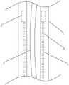
图1是本发明提出的可控弯导管及其控制手柄的一种实施例的立体图。FIG. 1 is a perspective view of an embodiment of the controllable curved conduit and its control handle proposed by the present invention.
图2是发明提出的可控弯导管及其控制手柄的一种实施例中可控弯导管、牵引丝和导丝的结构示意图。2 is a schematic structural diagram of a controllable bend catheter, a traction wire and a guide wire in an embodiment of the controllable bend catheter and its control handle proposed by the invention.
图3是发明提出的可控弯导管及其控制手柄的一种实施例中可控弯导管、牵引丝、导丝和拉丝环的结构示意图。3 is a schematic structural diagram of a controllable bend catheter, a traction wire, a guide wire and a wire drawing ring in an embodiment of the controllable bend catheter and its control handle proposed by the invention.
图4是发明提出的可控弯导管及其控制手柄的一种实施例中聚合物外层、金属将强层和聚合物内层的结构示意图。4 is a schematic structural diagram of an outer polymer layer, a metal strong layer and an inner polymer layer in an embodiment of the controllable bend catheter and its control handle proposed by the invention.
图5是本发明提出的可控弯导管及其控制手柄的一种实施例除去端部上盖和柄部上盖后的立体图。5 is a perspective view of an embodiment of the controllable bend conduit and its control handle proposed by the present invention after removing the upper cover of the end portion and the upper cover of the handle portion.
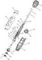
图6是本发明提出的可控弯导管及其控制手柄的一种实施例的爆炸图。FIG. 6 is an exploded view of an embodiment of the controllable curved conduit and its control handle proposed by the present invention.
图7是本发明提出的可控弯导管及其控制手柄的一种实施例中芯杆的立体图。7 is a perspective view of a core rod in an embodiment of the controllable curved conduit and its control handle proposed by the present invention.
图中:1、可控弯导管;2、导丝;3、拉丝腔;4、牵引丝;5、接丝环;6、聚合物内层;7、金属加强层;8、聚合物外层;9、合金丝弹簧圈;10、合金丝编织管;11、控制手柄;12、端部上盖;13、端部下盖;14、旋钮管;15、柄部上盖;16、柄部下盖;17、止血阀;18、芯杆;19、接丝螺杆件;20、应力端;21、远端限位块;22、滑轨杆;23、近端限位块;24、杆座;25、螺杆部;26、接丝部;27、内引丝孔;28、远端限位环片;29、外引丝孔;30、近端限位环片;31、走丝柱;32、保护壁;33、封堵片;34、第一接丝孔;35、第二接丝孔;36、远端卡圈;37、近端卡圈;38、第一橡胶塞;39、第二橡胶塞;40、圆孔;41、十字切口;42、注胶孔;43、摩擦纹理。In the figure: 1. Controllable bend catheter; 2. Guide wire; 3. Drawing cavity; 4. Pull wire; 5. Wire connection ring; 6. Inner polymer layer; 7. Metal reinforcement layer; ;9. Alloy wire spring coil; 10. Alloy wire braided tube; 11. Control handle; 12. Upper cover of the end; 13. Lower cover of the end; 14. Knob tube; 15. Upper cover of the handle; 16. Lower cover of the handle ; 17, hemostatic valve; 18, core rod; 19, wire screw parts; 20, stress end; 21, distal limit block; 22, slide rail rod; 23, proximal limit block; 24, rod seat; 25, screw part; 26, wire connection part; 27, inner wire hole; 28, distal limit ring; 29, outer wire hole; 30, proximal limit ring; 31, wire travel column; 32 , protective wall; 33, blocking sheet; 34, the first wire hole; 35, the second wire hole; 36, the distal collar; 37, the proximal collar; 38, the first rubber plug; 39, the first Two rubber plugs; 40, round hole; 41, cross cut; 42, glue injection hole; 43, friction texture.
具体实施方式Detailed ways
下面结合具体实施例,对本发明的内容做进一步的详细说明(在医疗器械领域中,远端指医疗器械上由手术者掌控或在人体外的一端,近端指医疗器械上发挥诊断/治疗作用或在人体中的另一端,由此延伸定义远近方向,并据此命名单个零件的远端和近端方便详细说明):The content of the present invention will be described in further detail below with reference to specific embodiments (in the field of medical devices, the distal end refers to the end of the medical device that is controlled by the operator or outside the human body, and the proximal end refers to the medical device that plays a diagnostic/therapeutic role. Or at the other end in the human body, whereby the extension defines the far and near directions, and the distal and proximal ends of the individual parts are named accordingly to facilitate elaboration):
结合图1至图7,本实施例是相互配合的可控弯导管和控制手柄,用于介入治疗手术,例如介入栓塞手术等,其中:1 to 7, the present embodiment is a controllable curved catheter and a control handle that cooperate with each other, which are used for interventional treatment operations, such as interventional embolization operations, etc., wherein:
可控弯导管1,可控弯导管1管腔中设有导丝2且壁厚中平行于轴向设有一对拉丝腔3,一对拉丝腔3关于可控弯导管1中轴对称且内部均设有牵引丝4,可控弯导管1远端具有柔顺性且壁厚中固定有接丝环5,牵引丝4远端连接固定接丝环5,近端贯穿可控弯导管1外壁,一对牵引丝4具有不同长度,可控弯导管1由内而外设有聚合物内层6、金属加强层7和聚合物内层6,一对拉丝腔3位于聚合物内层6和金属加强层7间;A controllable bend catheter 1, a
控制手柄11,控制手柄11外部由远及近依次设有端部上盖12、端部下盖13、旋钮管14、柄部上盖15、柄部下盖16和止血阀17,内部设有芯杆18和接丝螺杆件19,端部上盖12和端部下盖13、柄部上盖15和柄部下盖16两两插卡固定、上下盖合且两端开口,端部上盖12和端部下盖13近端均插卡固定于旋钮管14中轴向限位,柄部上盖15和柄部下盖16远端插卡固定于旋钮管14中轴向限位,旋钮管14中部呈环状突起且外壁设有摩擦纹理43,摩擦纹理43变现为平行于自身中轴的条形凸起,芯杆18由远及近依次设有应力端20、远端限位块21、滑轨杆22、近端限位块23和杆座24,内部轴向上贯穿开孔,接丝螺杆件19远端设有螺杆部25,近端设有接丝部26,内部轴向上贯穿开孔,应力端20为中空圆台形且伸出端部上盖12和端部下盖13,接丝螺杆件19内孔和滑轨杆22外沿截面均为正六边形,滑轨杆22外壁设有一对内引丝孔27和有若干注胶孔42,一对内引丝孔27关于滑轨杆22中轴对称,接丝螺杆件19恰好套合滑轨杆22周向限位轴向滑移,螺杆部25外壁设有螺纹,接丝部26远端设有远端限位环片28,中部外壁设有外引丝孔29,近端设有近端限位环片30,远端限位环片28和近端限位环片30均突出于螺杆部25外壁,近端限位块23远端突出于滑轨杆22外壁且近端外壁对应一侧内引丝孔27处设有走丝柱31和保护壁32,保护壁32呈半圆柱面状且开口朝向近端限位块23远端,走丝柱31和保护壁32同轴且中轴垂直于滑轨杆22中轴,柄部上盖15和柄部下盖16内壁设有封堵片33,走丝柱31端头插卡固定于封堵片33中且保护壁32抵接封堵片33,近端限位环片30上对应一对内引丝孔27处设有一对第一接丝孔34,近端限位环片30上邻近封堵片33同侧第一接丝孔34处设有第二接丝孔35,旋钮管14内壁设有螺纹且恰好螺合螺杆部25,端部上盖12和端部下盖13内壁设有远端卡圈36,柄部上盖15和柄部下盖16内壁设有近端卡圈37,远端限位块21插卡固定于远端卡圈36中周向限位,杆座24插卡固定于近端卡圈37中周向限位,止血阀17远端插卡固定于柄部上盖15和柄部下盖16开口中并封堵杆座24开口;The control handle 11, the control handle 11 is provided with an
可控弯导管1依次贯穿止血阀17和芯杆18,一对牵引丝4分别依次贯穿内引丝孔27、外引丝孔29和第一接丝孔34,具有较大长度的牵引丝4绕过走丝柱31连接固定第二接丝孔35,具有较小长度的牵引丝4直接连接固定第一接丝孔34,止血阀17近端开口中由远及近依次封堵有第一橡胶塞38和第二橡胶塞39,第一橡胶塞38中部设有圆孔40,第二橡胶塞39中部设有十字切口41,可控弯导管1依次贯穿十字切口41和圆孔40;The controllable bend catheter 1 passes through the
在上述实施例以及本发明的其他实施例中:In the above-described embodiments and other embodiments of the present invention:
金属加强层7由合金丝弹簧圈9和/或合金丝编织管10构成,如图4所述,金属加强层7可以是单层的合金丝编织管10(a),也可以是单层的合金丝弹簧圈9(b),也可以是合金丝编织管10拼接合金丝弹簧圈9形成单层结构(c),也可以单层的合金丝编织管10和单层的合金丝弹簧圈9内外套合形成两层结构(d),也可以是a、b、c和d四种情况随意组合形成的多层结构;The metal reinforcement layer 7 is composed of an alloy wire spring coil 9 and/or an alloy wire braided
芯杆18通过注胶孔42注胶与可控弯导管1胶粘固定,避免可控弯导管1进入人体工作中与芯杆18脱离影响手术,端部上盖12和端部下盖13、柄部上盖15和柄部下盖16两两插卡盖合时胶粘加固,使控制手柄11外壳结构更加牢靠;The
牵引丝4为钨丝、镍钛丝或者不锈钢丝等合金丝中的一种,具有优秀的强度和韧性;The
螺杆部25中部某处位于旋钮管14近端开口处时一对牵引丝4留在拉丝腔3中部分具有一致长度,此时导管远端不发生弯曲,当转动旋钮管14带动螺杆部25向芯杆18远端移动时,近端限位环片30带动一对牵引丝4远端同步向芯杆18远端移动,使总长度较长且近端连接固定第二接丝孔35的牵引丝4上从第一接丝孔34绕过走丝柱31连接固定第二接丝孔35的部分长度变大而其他部分长度变小,因此该牵引丝4留在拉丝腔3中长度相比总长度较短且近端连接固定第一接丝孔34的牵引丝4留在拉丝腔3中长度小,导致具有柔顺性的可控弯导管1远端朝向总长度较长的牵引丝4一侧弯曲,当转动旋钮管14带动螺杆部25远端向芯杆18近端移动时,近端限位环片30带动一对牵引丝4远端同步向芯杆18近端移动,使总长度较长且近端连接固定第二接丝孔35的牵引丝4上从第一接丝孔34绕过走丝柱31连接固定第二接丝孔35的部分长度变小而其他部分长度变大,因此该牵引丝4留在拉丝腔3中长度相比总长度较短且近端连接固定第一接丝孔34的牵引丝4留在拉丝腔3中长度大,导致具有柔顺性的可控弯导管1远端朝向总长度较短的牵引丝4一侧弯曲,实现了导管的可控双向弯曲,其中,当近端限位环片30抵接近端限位块23时螺杆部25远端抵接旋钮管14近端开口,当远端限位环片28抵接旋钮管14近端开口时螺杆部25远端抵接远端限位块21,限定近端限位环片30行程长度为螺杆部25长度。此外。在本发明的实际设计生产中可以根据现实应用要求调整一对牵引丝4长度和近端限位环片30行程长度等因素获取期望的双向弯曲的角度和形状。When the middle part of the
上述实施例只为说明本发明的技术构思及特点,其目的在于让熟悉此项技术的人士能够了解本发明的内容并加以实施,并不能以此限制本发明的保护范围,凡根据本发明精神实质所作的等效变化或修饰,都应涵盖在本发明的保护范围内。The above-mentioned embodiments are only to illustrate the technical concept and characteristics of the present invention, and their purpose is to enable those who are familiar with the art to understand the content of the present invention and implement it, and cannot limit the scope of protection of the present invention with this, all according to the spirit of the present invention Substantially equivalent changes or modifications should be included within the protection scope of the present invention.
Claims (10)
Translated fromChinesePriority Applications (1)
| Application Number | Priority Date | Filing Date | Title |
|---|---|---|---|
| CN202210647878.9ACN114849017A (en) | 2022-06-08 | 2022-06-08 | Controllable bent catheter and control handle thereof |
Applications Claiming Priority (1)
| Application Number | Priority Date | Filing Date | Title |
|---|---|---|---|
| CN202210647878.9ACN114849017A (en) | 2022-06-08 | 2022-06-08 | Controllable bent catheter and control handle thereof |
Publications (1)
| Publication Number | Publication Date |
|---|---|
| CN114849017Atrue CN114849017A (en) | 2022-08-05 |
Family
ID=82625328
Family Applications (1)
| Application Number | Title | Priority Date | Filing Date |
|---|---|---|---|
| CN202210647878.9APendingCN114849017A (en) | 2022-06-08 | 2022-06-08 | Controllable bent catheter and control handle thereof |
Country Status (1)
| Country | Link |
|---|---|
| CN (1) | CN114849017A (en) |
Cited By (3)
| Publication number | Priority date | Publication date | Assignee | Title |
|---|---|---|---|---|
| CN115120843A (en)* | 2022-08-09 | 2022-09-30 | 环心医疗科技(苏州)有限公司 | Multi-segment controlled bend catheter with asymmetric bend profile |
| CN115708921A (en)* | 2023-01-09 | 2023-02-24 | 苏州汇禾医疗科技有限公司 | Handle of conveying system for interventional therapy and conveying system |
| CN116158855A (en)* | 2023-02-01 | 2023-05-26 | 极限人工智能有限公司 | Interventional catheter, driving system and surgical robot |
Citations (6)
| Publication number | Priority date | Publication date | Assignee | Title |
|---|---|---|---|---|
| US5383852A (en)* | 1992-12-04 | 1995-01-24 | C. R. Bard, Inc. | Catheter with independent proximal and distal control |
| US5571085A (en)* | 1995-03-24 | 1996-11-05 | Electro-Catheter Corporation | Steerable open lumen catheter |
| US20120089125A1 (en)* | 2010-10-08 | 2012-04-12 | Greatbatch Ltd. | Bi-Directional Catheter Steering Handle |
| CN103877663A (en)* | 2012-12-20 | 2014-06-25 | 上海微创电生理医疗科技有限公司 | Bending control device for catheter and catheter comprising same |
| US20150231366A1 (en)* | 2012-06-19 | 2015-08-20 | Baylis Medical Company Inc. | Steerable Medical Device Handle |
| CN217960935U (en)* | 2022-06-08 | 2022-12-06 | 环心医疗科技(苏州)有限公司 | Controllable bent catheter and control handle thereof |
- 2022
- 2022-06-08CNCN202210647878.9Apatent/CN114849017A/enactivePending
Patent Citations (6)
| Publication number | Priority date | Publication date | Assignee | Title |
|---|---|---|---|---|
| US5383852A (en)* | 1992-12-04 | 1995-01-24 | C. R. Bard, Inc. | Catheter with independent proximal and distal control |
| US5571085A (en)* | 1995-03-24 | 1996-11-05 | Electro-Catheter Corporation | Steerable open lumen catheter |
| US20120089125A1 (en)* | 2010-10-08 | 2012-04-12 | Greatbatch Ltd. | Bi-Directional Catheter Steering Handle |
| US20150231366A1 (en)* | 2012-06-19 | 2015-08-20 | Baylis Medical Company Inc. | Steerable Medical Device Handle |
| CN103877663A (en)* | 2012-12-20 | 2014-06-25 | 上海微创电生理医疗科技有限公司 | Bending control device for catheter and catheter comprising same |
| CN217960935U (en)* | 2022-06-08 | 2022-12-06 | 环心医疗科技(苏州)有限公司 | Controllable bent catheter and control handle thereof |
Cited By (4)
| Publication number | Priority date | Publication date | Assignee | Title |
|---|---|---|---|---|
| CN115120843A (en)* | 2022-08-09 | 2022-09-30 | 环心医疗科技(苏州)有限公司 | Multi-segment controlled bend catheter with asymmetric bend profile |
| CN115708921A (en)* | 2023-01-09 | 2023-02-24 | 苏州汇禾医疗科技有限公司 | Handle of conveying system for interventional therapy and conveying system |
| CN116158855A (en)* | 2023-02-01 | 2023-05-26 | 极限人工智能有限公司 | Interventional catheter, driving system and surgical robot |
| CN116158855B (en)* | 2023-02-01 | 2023-10-13 | 极限人工智能有限公司 | Interventional catheter, driving system and surgical robot |
Similar Documents
| Publication | Publication Date | Title |
|---|---|---|
| CN114849017A (en) | Controllable bent catheter and control handle thereof | |
| JP7311083B2 (en) | steerable guide catheter | |
| US9713694B2 (en) | Low profile catheter assembly | |
| US9572957B2 (en) | Steerable medical devices and steering assemblies | |
| JP5307275B2 (en) | Combination of guide sheath and catheter | |
| CN104640583B (en) | blocked access system | |
| US20050228364A1 (en) | Tunneler device | |
| JPH0441621B2 (en) | ||
| CN103861195A (en) | Super-smooth guide wire for use in transradial coronary intervention | |
| CN113520667B (en) | Aortic membrane puncture system with angiography function | |
| CN117582252B (en) | An interventional therapy system and an ultrasonic catheter used for interventional therapy | |
| US20130317542A1 (en) | Steerable delivery system | |
| CN114366214A (en) | A kind of hydrophilic guide occlusion guide wire | |
| WO2024217492A1 (en) | Outer catheter, conveying assembly and conveying system | |
| CN118593089A (en) | Remote intracardiac adjustable curved sheath tube device and system | |
| WO2024183672A1 (en) | Cardiac pacemaker electrode wire delivery sheath | |
| CN217526048U (en) | Adjustable bent sheath | |
| CN217960935U (en) | Controllable bent catheter and control handle thereof | |
| CN118320266A (en) | Catheter for CTO forward opening | |
| WO2020219453A1 (en) | Drainage catheter with suture lumen | |
| US11565081B1 (en) | Catheter and systems for providing radial artery access of at least one of a contralateral subclavian artery and an internal mammary artery of a patient for diagnostic and interventional angiography | |
| WO2023028531A1 (en) | Pigtail dilator system | |
| CN105339034A (en) | Adaptive guidance system for ventricular septal defect occlusion under ultrasound guidance | |
| CN114917455A (en) | Guiding catheter inner core and no-sheath guiding catheter system | |
| CN220237525U (en) | Catheter sheath assembly for interventional therapy |
Legal Events
| Date | Code | Title | Description |
|---|---|---|---|
| PB01 | Publication | ||
| PB01 | Publication | ||
| SE01 | Entry into force of request for substantive examination | ||
| SE01 | Entry into force of request for substantive examination |