CN114845650A - Thermal cutting element, electrosurgical instrument including thermal cutting element, and method of manufacture - Google Patents
Thermal cutting element, electrosurgical instrument including thermal cutting element, and method of manufactureDownload PDFInfo
- Publication number
- CN114845650A CN114845650ACN202080088545.6ACN202080088545ACN114845650ACN 114845650 ACN114845650 ACN 114845650ACN 202080088545 ACN202080088545 ACN 202080088545ACN 114845650 ACN114845650 ACN 114845650A
- Authority
- CN
- China
- Prior art keywords
- peo
- thermal cutting
- heating element
- cutting element
- substrate
- Prior art date
- Legal status (The legal status is an assumption and is not a legal conclusion. Google has not performed a legal analysis and makes no representation as to the accuracy of the status listed.)
- Pending
Links
- 238000005520cutting processMethods0.000titleclaimsabstractdescription84
- 238000000034methodMethods0.000titleclaimsabstractdescription42
- 238000004519manufacturing processMethods0.000titleclaimsabstractdescription13
- 238000010438heat treatmentMethods0.000claimsabstractdescription79
- 239000000758substrateSubstances0.000claimsabstractdescription74
- 238000007745plasma electrolytic oxidation reactionMethods0.000claimsabstractdescription66
- 239000011248coating agentSubstances0.000claimsabstractdescription31
- 238000000576coating methodMethods0.000claimsabstractdescription31
- 238000004544sputter depositionMethods0.000claimsdescription12
- 238000007650screen-printingMethods0.000claimsdescription8
- 230000008878couplingEffects0.000claimsdescription6
- 238000010168coupling processMethods0.000claimsdescription6
- 238000005859coupling reactionMethods0.000claimsdescription6
- 229910052782aluminiumInorganic materials0.000claimsdescription5
- XAGFODPZIPBFFR-UHFFFAOYSA-NaluminiumChemical compound[Al]XAGFODPZIPBFFR-UHFFFAOYSA-N0.000claimsdescription5
- 239000004020conductorSubstances0.000claimsdescription4
- RTAQQCXQSZGOHL-UHFFFAOYSA-NTitaniumChemical compound[Ti]RTAQQCXQSZGOHL-UHFFFAOYSA-N0.000claimsdescription3
- 239000012777electrically insulating materialSubstances0.000claimsdescription3
- 229910052719titaniumInorganic materials0.000claimsdescription3
- 239000010936titaniumSubstances0.000claimsdescription3
- 229910000838Al alloyInorganic materials0.000claimsdescription2
- 229910001069Ti alloyInorganic materials0.000claimsdescription2
- 239000012636effectorSubstances0.000description35
- 239000000463materialSubstances0.000description10
- 230000004913activationEffects0.000description9
- 238000002048anodisation reactionMethods0.000description5
- 230000000712assemblyEffects0.000description5
- 238000000429assemblyMethods0.000description5
- PXHVJJICTQNCMI-UHFFFAOYSA-NNickelChemical compound[Ni]PXHVJJICTQNCMI-UHFFFAOYSA-N0.000description4
- 230000003213activating effectEffects0.000description4
- 230000008569processEffects0.000description4
- 229910000078germaneInorganic materials0.000description3
- 238000003466weldingMethods0.000description3
- VYPSYNLAJGMNEJ-UHFFFAOYSA-NSilicium dioxideChemical compoundO=[Si]=OVYPSYNLAJGMNEJ-UHFFFAOYSA-N0.000description2
- 230000009471actionEffects0.000description2
- 239000000853adhesiveSubstances0.000description2
- 230000001070adhesive effectEffects0.000description2
- 239000000919ceramicSubstances0.000description2
- 238000009713electroplatingMethods0.000description2
- 239000012530fluidSubstances0.000description2
- 230000002439hemostatic effectEffects0.000description2
- 239000011810insulating materialSubstances0.000description2
- 238000011068loading methodMethods0.000description2
- 230000008018meltingEffects0.000description2
- 238000002844meltingMethods0.000description2
- 229910052751metalInorganic materials0.000description2
- 239000002184metalSubstances0.000description2
- 230000004048modificationEffects0.000description2
- 238000012986modificationMethods0.000description2
- 229910052759nickelInorganic materials0.000description2
- 230000003647oxidationEffects0.000description2
- 238000007254oxidation reactionMethods0.000description2
- BASFCYQUMIYNBI-UHFFFAOYSA-NplatinumChemical compound[Pt]BASFCYQUMIYNBI-UHFFFAOYSA-N0.000description2
- 238000002604ultrasonographyMethods0.000description2
- RYGMFSIKBFXOCR-UHFFFAOYSA-NCopperChemical compound[Cu]RYGMFSIKBFXOCR-UHFFFAOYSA-N0.000description1
- 239000004677NylonSubstances0.000description1
- MXRIRQGCELJRSN-UHFFFAOYSA-NO.O.O.[Al]Chemical compoundO.O.O.[Al]MXRIRQGCELJRSN-UHFFFAOYSA-N0.000description1
- 239000004111Potassium silicateSubstances0.000description1
- 239000004115Sodium SilicateSubstances0.000description1
- 239000012670alkaline solutionSubstances0.000description1
- 229910045601alloyInorganic materials0.000description1
- 239000000956alloySubstances0.000description1
- 238000007743anodisingMethods0.000description1
- 230000004888barrier functionEffects0.000description1
- 230000008901benefitEffects0.000description1
- 239000011230binding agentSubstances0.000description1
- 230000005540biological transmissionEffects0.000description1
- 238000005219brazingMethods0.000description1
- 238000005266castingMethods0.000description1
- 230000015556catabolic processEffects0.000description1
- 238000003486chemical etchingMethods0.000description1
- 238000006243chemical reactionMethods0.000description1
- 238000004140cleaningMethods0.000description1
- 238000004590computer programMethods0.000description1
- 229910052802copperInorganic materials0.000description1
- 239000010949copperSubstances0.000description1
- 229910052593corundumInorganic materials0.000description1
- 239000010431corundumSubstances0.000description1
- 238000005336crackingMethods0.000description1
- 238000005238degreasingMethods0.000description1
- 238000000280densificationMethods0.000description1
- 238000000151depositionMethods0.000description1
- 230000008021depositionEffects0.000description1
- 238000005137deposition processMethods0.000description1
- 238000010586diagramMethods0.000description1
- 238000010292electrical insulationMethods0.000description1
- 239000003792electrolyteSubstances0.000description1
- 230000007613environmental effectEffects0.000description1
- 238000005242forgingMethods0.000description1
- 230000006870functionEffects0.000description1
- 239000011521glassSubstances0.000description1
- 239000003292glueSubstances0.000description1
- 238000002955isolationMethods0.000description1
- 229910000953kanthalInorganic materials0.000description1
- 238000003754machiningMethods0.000description1
- 238000005259measurementMethods0.000description1
- 230000007246mechanismEffects0.000description1
- 229910001120nichromeInorganic materials0.000description1
- 229920001778nylonPolymers0.000description1
- 229910052697platinumInorganic materials0.000description1
- 229920000052poly(p-xylylene)Polymers0.000description1
- 239000004810polytetrafluoroethyleneSubstances0.000description1
- 229920001343polytetrafluoroethylenePolymers0.000description1
- 229910052913potassium silicateInorganic materials0.000description1
- 235000019353potassium silicateNutrition0.000description1
- NNHHDJVEYQHLHG-UHFFFAOYSA-Npotassium silicateChemical compound[K+].[K+].[O-][Si]([O-])=ONNHHDJVEYQHLHG-UHFFFAOYSA-N0.000description1
- 230000000750progressive effectEffects0.000description1
- 230000004044responseEffects0.000description1
- 238000005488sandblastingMethods0.000description1
- 229910052594sapphireInorganic materials0.000description1
- 239000000377silicon dioxideSubstances0.000description1
- 235000012239silicon dioxideNutrition0.000description1
- 238000005245sinteringMethods0.000description1
- 229910052911sodium silicateInorganic materials0.000description1
- NTHWMYGWWRZVTN-UHFFFAOYSA-Nsodium silicateChemical compound[Na+].[Na+].[O-][Si]([O-])=ONTHWMYGWWRZVTN-UHFFFAOYSA-N0.000description1
- 238000005476solderingMethods0.000description1
- 239000010935stainless steelSubstances0.000description1
- 229910001220stainless steelInorganic materials0.000description1
- 230000003746surface roughnessEffects0.000description1
- 238000012546transferMethods0.000description1
- 238000013519translationMethods0.000description1
- XLYOFNOQVPJJNP-UHFFFAOYSA-NwaterSubstancesOXLYOFNOQVPJJNP-UHFFFAOYSA-N0.000description1
Images


Classifications
- C—CHEMISTRY; METALLURGY
- C25—ELECTROLYTIC OR ELECTROPHORETIC PROCESSES; APPARATUS THEREFOR
- C25D—PROCESSES FOR THE ELECTROLYTIC OR ELECTROPHORETIC PRODUCTION OF COATINGS; ELECTROFORMING; APPARATUS THEREFOR
- C25D11/00—Electrolytic coating by surface reaction, i.e. forming conversion layers
- C25D11/02—Anodisation
- A—HUMAN NECESSITIES
- A61—MEDICAL OR VETERINARY SCIENCE; HYGIENE
- A61B—DIAGNOSIS; SURGERY; IDENTIFICATION
- A61B18/00—Surgical instruments, devices or methods for transferring non-mechanical forms of energy to or from the body
- A61B18/04—Surgical instruments, devices or methods for transferring non-mechanical forms of energy to or from the body by heating
- A61B18/08—Surgical instruments, devices or methods for transferring non-mechanical forms of energy to or from the body by heating by means of electrically-heated probes
- A61B18/082—Probes or electrodes therefor
- A61B18/085—Forceps, scissors
- A—HUMAN NECESSITIES
- A61—MEDICAL OR VETERINARY SCIENCE; HYGIENE
- A61B—DIAGNOSIS; SURGERY; IDENTIFICATION
- A61B18/00—Surgical instruments, devices or methods for transferring non-mechanical forms of energy to or from the body
- A61B18/04—Surgical instruments, devices or methods for transferring non-mechanical forms of energy to or from the body by heating
- A61B18/12—Surgical instruments, devices or methods for transferring non-mechanical forms of energy to or from the body by heating by passing a current through the tissue to be heated, e.g. high-frequency current
- A61B18/14—Probes or electrodes therefor
- A61B18/1442—Probes having pivoting end effectors, e.g. forceps
- A61B18/1445—Probes having pivoting end effectors, e.g. forceps at the distal end of a shaft, e.g. forceps or scissors at the end of a rigid rod
- B—PERFORMING OPERATIONS; TRANSPORTING
- B21—MECHANICAL METAL-WORKING WITHOUT ESSENTIALLY REMOVING MATERIAL; PUNCHING METAL
- B21D—WORKING OR PROCESSING OF SHEET METAL OR METAL TUBES, RODS OR PROFILES WITHOUT ESSENTIALLY REMOVING MATERIAL; PUNCHING METAL
- B21D22/00—Shaping without cutting, by stamping, spinning, or deep-drawing
- B21D22/02—Stamping using rigid devices or tools
- B—PERFORMING OPERATIONS; TRANSPORTING
- B41—PRINTING; LINING MACHINES; TYPEWRITERS; STAMPS
- B41M—PRINTING, DUPLICATING, MARKING, OR COPYING PROCESSES; COLOUR PRINTING
- B41M1/00—Inking and printing with a printer's forme
- B41M1/12—Stencil printing; Silk-screen printing
- B—PERFORMING OPERATIONS; TRANSPORTING
- B41—PRINTING; LINING MACHINES; TYPEWRITERS; STAMPS
- B41M—PRINTING, DUPLICATING, MARKING, OR COPYING PROCESSES; COLOUR PRINTING
- B41M3/00—Printing processes to produce particular kinds of printed work, e.g. patterns
- B41M3/006—Patterns of chemical products used for a specific purpose, e.g. pesticides, perfumes, adhesive patterns; use of microencapsulated material; Printing on smoking articles
- C—CHEMISTRY; METALLURGY
- C23—COATING METALLIC MATERIAL; COATING MATERIAL WITH METALLIC MATERIAL; CHEMICAL SURFACE TREATMENT; DIFFUSION TREATMENT OF METALLIC MATERIAL; COATING BY VACUUM EVAPORATION, BY SPUTTERING, BY ION IMPLANTATION OR BY CHEMICAL VAPOUR DEPOSITION, IN GENERAL; INHIBITING CORROSION OF METALLIC MATERIAL OR INCRUSTATION IN GENERAL
- C23C—COATING METALLIC MATERIAL; COATING MATERIAL WITH METALLIC MATERIAL; SURFACE TREATMENT OF METALLIC MATERIAL BY DIFFUSION INTO THE SURFACE, BY CHEMICAL CONVERSION OR SUBSTITUTION; COATING BY VACUUM EVAPORATION, BY SPUTTERING, BY ION IMPLANTATION OR BY CHEMICAL VAPOUR DEPOSITION, IN GENERAL
- C23C14/00—Coating by vacuum evaporation, by sputtering or by ion implantation of the coating forming material
- C23C14/02—Pretreatment of the material to be coated
- C23C14/024—Deposition of sublayers, e.g. to promote adhesion of the coating
- C—CHEMISTRY; METALLURGY
- C23—COATING METALLIC MATERIAL; COATING MATERIAL WITH METALLIC MATERIAL; CHEMICAL SURFACE TREATMENT; DIFFUSION TREATMENT OF METALLIC MATERIAL; COATING BY VACUUM EVAPORATION, BY SPUTTERING, BY ION IMPLANTATION OR BY CHEMICAL VAPOUR DEPOSITION, IN GENERAL; INHIBITING CORROSION OF METALLIC MATERIAL OR INCRUSTATION IN GENERAL
- C23C—COATING METALLIC MATERIAL; COATING MATERIAL WITH METALLIC MATERIAL; SURFACE TREATMENT OF METALLIC MATERIAL BY DIFFUSION INTO THE SURFACE, BY CHEMICAL CONVERSION OR SUBSTITUTION; COATING BY VACUUM EVAPORATION, BY SPUTTERING, BY ION IMPLANTATION OR BY CHEMICAL VAPOUR DEPOSITION, IN GENERAL
- C23C14/00—Coating by vacuum evaporation, by sputtering or by ion implantation of the coating forming material
- C23C14/04—Coating on selected surface areas, e.g. using masks
- C23C14/042—Coating on selected surface areas, e.g. using masks using masks
- C—CHEMISTRY; METALLURGY
- C23—COATING METALLIC MATERIAL; COATING MATERIAL WITH METALLIC MATERIAL; CHEMICAL SURFACE TREATMENT; DIFFUSION TREATMENT OF METALLIC MATERIAL; COATING BY VACUUM EVAPORATION, BY SPUTTERING, BY ION IMPLANTATION OR BY CHEMICAL VAPOUR DEPOSITION, IN GENERAL; INHIBITING CORROSION OF METALLIC MATERIAL OR INCRUSTATION IN GENERAL
- C23C—COATING METALLIC MATERIAL; COATING MATERIAL WITH METALLIC MATERIAL; SURFACE TREATMENT OF METALLIC MATERIAL BY DIFFUSION INTO THE SURFACE, BY CHEMICAL CONVERSION OR SUBSTITUTION; COATING BY VACUUM EVAPORATION, BY SPUTTERING, BY ION IMPLANTATION OR BY CHEMICAL VAPOUR DEPOSITION, IN GENERAL
- C23C14/00—Coating by vacuum evaporation, by sputtering or by ion implantation of the coating forming material
- C23C14/22—Coating by vacuum evaporation, by sputtering or by ion implantation of the coating forming material characterised by the process of coating
- C23C14/34—Sputtering
- C—CHEMISTRY; METALLURGY
- C23—COATING METALLIC MATERIAL; COATING MATERIAL WITH METALLIC MATERIAL; CHEMICAL SURFACE TREATMENT; DIFFUSION TREATMENT OF METALLIC MATERIAL; COATING BY VACUUM EVAPORATION, BY SPUTTERING, BY ION IMPLANTATION OR BY CHEMICAL VAPOUR DEPOSITION, IN GENERAL; INHIBITING CORROSION OF METALLIC MATERIAL OR INCRUSTATION IN GENERAL
- C23C—COATING METALLIC MATERIAL; COATING MATERIAL WITH METALLIC MATERIAL; SURFACE TREATMENT OF METALLIC MATERIAL BY DIFFUSION INTO THE SURFACE, BY CHEMICAL CONVERSION OR SUBSTITUTION; COATING BY VACUUM EVAPORATION, BY SPUTTERING, BY ION IMPLANTATION OR BY CHEMICAL VAPOUR DEPOSITION, IN GENERAL
- C23C28/00—Coating for obtaining at least two superposed coatings either by methods not provided for in a single one of groups C23C2/00 - C23C26/00 or by combinations of methods provided for in subclasses C23C and C25C or C25D
- C23C28/04—Coating for obtaining at least two superposed coatings either by methods not provided for in a single one of groups C23C2/00 - C23C26/00 or by combinations of methods provided for in subclasses C23C and C25C or C25D only coatings of inorganic non-metallic material
- C23C28/042—Coating for obtaining at least two superposed coatings either by methods not provided for in a single one of groups C23C2/00 - C23C26/00 or by combinations of methods provided for in subclasses C23C and C25C or C25D only coatings of inorganic non-metallic material including a refractory ceramic layer, e.g. refractory metal oxides, ZrO2, rare earth oxides
- C—CHEMISTRY; METALLURGY
- C23—COATING METALLIC MATERIAL; COATING MATERIAL WITH METALLIC MATERIAL; CHEMICAL SURFACE TREATMENT; DIFFUSION TREATMENT OF METALLIC MATERIAL; COATING BY VACUUM EVAPORATION, BY SPUTTERING, BY ION IMPLANTATION OR BY CHEMICAL VAPOUR DEPOSITION, IN GENERAL; INHIBITING CORROSION OF METALLIC MATERIAL OR INCRUSTATION IN GENERAL
- C23C—COATING METALLIC MATERIAL; COATING MATERIAL WITH METALLIC MATERIAL; SURFACE TREATMENT OF METALLIC MATERIAL BY DIFFUSION INTO THE SURFACE, BY CHEMICAL CONVERSION OR SUBSTITUTION; COATING BY VACUUM EVAPORATION, BY SPUTTERING, BY ION IMPLANTATION OR BY CHEMICAL VAPOUR DEPOSITION, IN GENERAL
- C23C28/00—Coating for obtaining at least two superposed coatings either by methods not provided for in a single one of groups C23C2/00 - C23C26/00 or by combinations of methods provided for in subclasses C23C and C25C or C25D
- C23C28/30—Coatings combining at least one metallic layer and at least one inorganic non-metallic layer
- C23C28/34—Coatings combining at least one metallic layer and at least one inorganic non-metallic layer including at least one inorganic non-metallic material layer, e.g. metal carbide, nitride, boride, silicide layer and their mixtures, enamels, phosphates and sulphates
- C23C28/345—Coatings combining at least one metallic layer and at least one inorganic non-metallic layer including at least one inorganic non-metallic material layer, e.g. metal carbide, nitride, boride, silicide layer and their mixtures, enamels, phosphates and sulphates with at least one oxide layer
- C—CHEMISTRY; METALLURGY
- C25—ELECTROLYTIC OR ELECTROPHORETIC PROCESSES; APPARATUS THEREFOR
- C25D—PROCESSES FOR THE ELECTROLYTIC OR ELECTROPHORETIC PRODUCTION OF COATINGS; ELECTROFORMING; APPARATUS THEREFOR
- C25D11/00—Electrolytic coating by surface reaction, i.e. forming conversion layers
- C25D11/02—Anodisation
- C25D11/024—Anodisation under pulsed or modulated current or potential
- C—CHEMISTRY; METALLURGY
- C25—ELECTROLYTIC OR ELECTROPHORETIC PROCESSES; APPARATUS THEREFOR
- C25D—PROCESSES FOR THE ELECTROLYTIC OR ELECTROPHORETIC PRODUCTION OF COATINGS; ELECTROFORMING; APPARATUS THEREFOR
- C25D11/00—Electrolytic coating by surface reaction, i.e. forming conversion layers
- C25D11/02—Anodisation
- C25D11/026—Anodisation with spark discharge
- C—CHEMISTRY; METALLURGY
- C25—ELECTROLYTIC OR ELECTROPHORETIC PROCESSES; APPARATUS THEREFOR
- C25D—PROCESSES FOR THE ELECTROLYTIC OR ELECTROPHORETIC PRODUCTION OF COATINGS; ELECTROFORMING; APPARATUS THEREFOR
- C25D11/00—Electrolytic coating by surface reaction, i.e. forming conversion layers
- C25D11/02—Anodisation
- C25D11/04—Anodisation of aluminium or alloys based thereon
- C25D11/06—Anodisation of aluminium or alloys based thereon characterised by the electrolytes used
- C—CHEMISTRY; METALLURGY
- C25—ELECTROLYTIC OR ELECTROPHORETIC PROCESSES; APPARATUS THEREFOR
- C25D—PROCESSES FOR THE ELECTROLYTIC OR ELECTROPHORETIC PRODUCTION OF COATINGS; ELECTROFORMING; APPARATUS THEREFOR
- C25D11/00—Electrolytic coating by surface reaction, i.e. forming conversion layers
- C25D11/02—Anodisation
- C25D11/26—Anodisation of refractory metals or alloys based thereon
- A—HUMAN NECESSITIES
- A61—MEDICAL OR VETERINARY SCIENCE; HYGIENE
- A61B—DIAGNOSIS; SURGERY; IDENTIFICATION
- A61B17/00—Surgical instruments, devices or methods
- A61B2017/00526—Methods of manufacturing
- A—HUMAN NECESSITIES
- A61—MEDICAL OR VETERINARY SCIENCE; HYGIENE
- A61B—DIAGNOSIS; SURGERY; IDENTIFICATION
- A61B18/00—Surgical instruments, devices or methods for transferring non-mechanical forms of energy to or from the body
- A61B2018/00053—Mechanical features of the instrument of device
- A61B2018/00059—Material properties
- A61B2018/00071—Electrical conductivity
- A61B2018/00077—Electrical conductivity high, i.e. electrically conducting
- A—HUMAN NECESSITIES
- A61—MEDICAL OR VETERINARY SCIENCE; HYGIENE
- A61B—DIAGNOSIS; SURGERY; IDENTIFICATION
- A61B18/00—Surgical instruments, devices or methods for transferring non-mechanical forms of energy to or from the body
- A61B2018/00053—Mechanical features of the instrument of device
- A61B2018/00059—Material properties
- A61B2018/00071—Electrical conductivity
- A61B2018/00083—Electrical conductivity low, i.e. electrically insulating
- A—HUMAN NECESSITIES
- A61—MEDICAL OR VETERINARY SCIENCE; HYGIENE
- A61B—DIAGNOSIS; SURGERY; IDENTIFICATION
- A61B18/00—Surgical instruments, devices or methods for transferring non-mechanical forms of energy to or from the body
- A61B2018/00053—Mechanical features of the instrument of device
- A61B2018/00107—Coatings on the energy applicator
- A—HUMAN NECESSITIES
- A61—MEDICAL OR VETERINARY SCIENCE; HYGIENE
- A61B—DIAGNOSIS; SURGERY; IDENTIFICATION
- A61B18/00—Surgical instruments, devices or methods for transferring non-mechanical forms of energy to or from the body
- A61B2018/00053—Mechanical features of the instrument of device
- A61B2018/00172—Connectors and adapters therefor
- A61B2018/00178—Electrical connectors
- A—HUMAN NECESSITIES
- A61—MEDICAL OR VETERINARY SCIENCE; HYGIENE
- A61B—DIAGNOSIS; SURGERY; IDENTIFICATION
- A61B18/00—Surgical instruments, devices or methods for transferring non-mechanical forms of energy to or from the body
- A61B2018/00571—Surgical instruments, devices or methods for transferring non-mechanical forms of energy to or from the body for achieving a particular surgical effect
- A61B2018/00589—Coagulation
- A—HUMAN NECESSITIES
- A61—MEDICAL OR VETERINARY SCIENCE; HYGIENE
- A61B—DIAGNOSIS; SURGERY; IDENTIFICATION
- A61B18/00—Surgical instruments, devices or methods for transferring non-mechanical forms of energy to or from the body
- A61B2018/00571—Surgical instruments, devices or methods for transferring non-mechanical forms of energy to or from the body for achieving a particular surgical effect
- A61B2018/00595—Cauterization
- A—HUMAN NECESSITIES
- A61—MEDICAL OR VETERINARY SCIENCE; HYGIENE
- A61B—DIAGNOSIS; SURGERY; IDENTIFICATION
- A61B18/00—Surgical instruments, devices or methods for transferring non-mechanical forms of energy to or from the body
- A61B2018/00571—Surgical instruments, devices or methods for transferring non-mechanical forms of energy to or from the body for achieving a particular surgical effect
- A61B2018/00607—Coagulation and cutting with the same instrument
- A—HUMAN NECESSITIES
- A61—MEDICAL OR VETERINARY SCIENCE; HYGIENE
- A61B—DIAGNOSIS; SURGERY; IDENTIFICATION
- A61B18/00—Surgical instruments, devices or methods for transferring non-mechanical forms of energy to or from the body
- A61B2018/00571—Surgical instruments, devices or methods for transferring non-mechanical forms of energy to or from the body for achieving a particular surgical effect
- A61B2018/0063—Sealing
- A—HUMAN NECESSITIES
- A61—MEDICAL OR VETERINARY SCIENCE; HYGIENE
- A61B—DIAGNOSIS; SURGERY; IDENTIFICATION
- A61B34/00—Computer-aided surgery; Manipulators or robots specially adapted for use in surgery
- A61B34/30—Surgical robots
Landscapes
- Chemical & Material Sciences (AREA)
- Engineering & Computer Science (AREA)
- Health & Medical Sciences (AREA)
- Chemical Kinetics & Catalysis (AREA)
- Materials Engineering (AREA)
- Metallurgy (AREA)
- Organic Chemistry (AREA)
- Life Sciences & Earth Sciences (AREA)
- Surgery (AREA)
- Mechanical Engineering (AREA)
- Public Health (AREA)
- Animal Behavior & Ethology (AREA)
- Otolaryngology (AREA)
- Plasma & Fusion (AREA)
- Physics & Mathematics (AREA)
- Biomedical Technology (AREA)
- Heart & Thoracic Surgery (AREA)
- Medical Informatics (AREA)
- Molecular Biology (AREA)
- Nuclear Medicine, Radiotherapy & Molecular Imaging (AREA)
- General Health & Medical Sciences (AREA)
- Veterinary Medicine (AREA)
- Electrochemistry (AREA)
- Inorganic Chemistry (AREA)
- General Chemical & Material Sciences (AREA)
- Pest Control & Pesticides (AREA)
- Ceramic Engineering (AREA)
- Surgical Instruments (AREA)
Abstract
Translated fromChinese
Description
Translated fromChinese相关申请的交叉引用CROSS-REFERENCE TO RELATED APPLICATIONS
本申请要求均于2019年12月21日提交的美国临时专利申请第62/952,232和62/952,234号的权益和优先权,所述美国临时专利申请中的每一个的全部内容在此通过引用并入本文中。This application claims the benefit of, and priority to, US Provisional Patent Application Nos. 62/952,232 and 62/952,234, both filed on December 21, 2019, the entire contents of each of which are hereby incorporated by reference herein. into this article.
技术领域technical field
本公开涉及外科器械,并且更具体地说,涉及热切割元件、包括热切割元件的电外科器械以及制造热切割元件的方法。The present disclosure relates to surgical instruments, and more particularly, to thermal cutting elements, electrosurgical instruments including thermal cutting elements, and methods of making thermal cutting elements.
背景技术Background technique
外科钳是一种钳状器械,所述钳状器械依靠其钳口构件之间的机械作用来抓握、夹持和约束组织。电外科钳利用机械夹紧作用和能量来加热组织以处理例如凝结、烧灼或密封组织。通常,一旦组织被处理,外科医生就必须准确地切除已处理的组织。因此,许多电外科钳被设计成包括在钳口构件之间推进以切割已处理的组织的刀。作为机械刀的替代方案,可以提供基于能量的组织切割元件以使用能量(例如,热、电外科、超声、光或其他合适的能量)来切割已处理的组织。A surgical forceps is a forceps-like instrument that relies on mechanical action between its jaw members to grasp, clamp, and restrain tissue. Electrosurgical forceps utilize mechanical clamping action and energy to heat tissue to treat, eg, coagulate, cauterize, or seal the tissue. Often, once the tissue has been processed, the surgeon must accurately excise the processed tissue. Accordingly, many electrosurgical forceps are designed to include a knife that is advanced between jaw members to cut the treated tissue. As an alternative to mechanical knives, energy-based tissue cutting elements may be provided to cut treated tissue using energy (eg, heat, electrosurgery, ultrasound, light, or other suitable energy).
发明内容SUMMARY OF THE INVENTION
如本文所用,术语“远侧”是指远离使用者的所述部分,而术语“近侧”是指更靠近使用者的所述部分。此外,在一致的程度上,本文详述的任何或所有方面可以与本文详述的任何或所有其它方面结合使用。As used herein, the term "distal" refers to the portion that is remote from the user, while the term "proximal" refers to the portion that is closer to the user. Furthermore, to the extent consistent, any or all aspects detailed herein may be used in conjunction with any or all other aspects detailed herein.
根据本公开的方面提供一种用于外科器械的热切割元件。所述热切割元件包括:基板;安置在基板上的PEO涂层;和加热元件,其安置在PEO涂层上并包括适于连接到不同电势的电能以加热所述加热元件的第一和第二端部部分。According to aspects of the present disclosure there is provided a thermal cutting element for a surgical instrument. The thermal cutting element includes: a substrate; a PEO coating disposed on the substrate; and a heating element disposed on the PEO coating and comprising first and second electrical energy adapted to be connected to different electrical potentials to heat the heating element. Two end parts.
在本公开的一方面中,加热元件在第一和第二端部部分之间限定连续电路迹线。In one aspect of the present disclosure, the heating element defines a continuous circuit trace between the first and second end portions.
在本公开的另一方面中,加热元件的第一和第二端部部分彼此邻近安置。In another aspect of the present disclosure, the first and second end portions of the heating element are positioned adjacent to each other.
在本公开的再一方面中,第一和第二电触点安置在加热元件的相应第一和第二端部部分上。第一和第二电触点被配置成便于将不同电势的电能分别连接到第一和第二端部部分。In yet another aspect of the present disclosure, first and second electrical contacts are disposed on respective first and second end portions of the heating element. The first and second electrical contacts are configured to facilitate connection of electrical energy at different potentials to the first and second end portions, respectively.
在本公开的又一方面中,基板由铝、钛、铝合金或钛合金形成。In yet another aspect of the present disclosure, the substrate is formed of aluminum, titanium, aluminum alloys, or titanium alloys.
在本公开的再又一方面中,PEO涂层限定约50微米至约150微米;在其他方面中约75微米至约125微米;在其他方面中约100微米的平均厚度。In yet another aspect of the present disclosure, the PEO coating defines an average thickness of about 50 microns to about 150 microns; in other aspects about 75 microns to about 125 microns; in other aspects about 100 microns.
在本公开的另一方面中,基板限定细长主体和从细长主体延伸的近侧连接法兰。加热元件的第一和第二端部部分安置在近侧连接法兰处。In another aspect of the present disclosure, the base plate defines an elongated body and a proximal connecting flange extending from the elongated body. The first and second end portions of the heating element are positioned at the proximal connecting flange.
根据本公开提供的外科器械的钳口构件包括:结构框架,其包括近侧法兰部分和远侧主体部分;钳口壳体,其包围结构框架的远侧主体部分;和组织处理板,其安置在钳口壳体顶上。组织处理板限定沿着其长度的至少一部分贯穿其中的纵向狭槽。钳口构件进一步包括热切割元件,其安置在钳口壳体内并沿着组织处理板的长度的至少一部分延伸穿过纵向狭槽的至少一部分。热切割元件可以被配置成类似于上文详述或本文提供的任何方面。A jaw member of a surgical instrument provided in accordance with the present disclosure includes: a structural frame including a proximal flange portion and a distal body portion; a jaw housing surrounding the distal body portion of the structural frame; and a tissue treatment plate Set on top of the jaw housing. The tissue treatment plate defines a longitudinal slot therethrough along at least a portion of its length. The jaw member further includes a thermal cutting element disposed within the jaw housing and extending through at least a portion of the longitudinal slot along at least a portion of the length of the tissue treatment plate. The thermal cutting elements may be configured similar to any of the aspects detailed above or provided herein.
在各方面中,组织处理板由导电材料形成并且适于连接到电外科能量源。在这类方面中,组织处理板与加热元件电隔离。In various aspects, the tissue treatment plate is formed of a conductive material and is adapted to be connected to an electrosurgical energy source. In such aspects, the tissue treatment plate is electrically isolated from the heating element.
在各方面中,热切割元件包括从其延伸到钳口壳体中的附接法兰。附接法兰便于将热切割元件附接在钳口壳体内。In various aspects, the thermal cutting element includes an attachment flange extending therefrom into the jaw housing. The attachment flange facilitates attachment of the thermal cutting element within the jaw housing.
根据本公开的方面提供的制造用于外科器械的热切割元件的方法包括:制造基板;经由等离子电解氧化(PEO)涂覆基板的至少一部分;和将加热元件安置在经PEO涂覆的基板的至少一部分上。A method of manufacturing a thermal cutting element for a surgical instrument provided in accordance with aspects of the present disclosure includes: manufacturing a substrate; coating at least a portion of the substrate via plasma electrolytic oxidation (PEO); and disposing a heating element on a portion of the PEO-coated substrate at least in part.
在本公开的一方面中,安置加热元件包括在经PEO涂覆的基板上形成连续电路迹线。连续电路迹线可以在加热元件的第一和第二端部部分之间延伸。在各方面中,在经PEO涂覆的基板上形成连续电路迹线包括形成电路迹线图案,其中电路迹线图案的第一和第二端部部分彼此邻近安置。In one aspect of the present disclosure, positioning the heating element includes forming continuous circuit traces on the PEO-coated substrate. A continuous circuit trace may extend between the first and second end portions of the heating element. In various aspects, forming the continuous circuit traces on the PEO-coated substrate includes forming a circuit trace pattern, wherein first and second end portions of the circuit trace pattern are positioned adjacent to each other.
在本公开的另一方面中,安置加热元件包括将加热元件溅射到经PEO涂覆的基板上。In another aspect of the present disclosure, disposing the heating element includes sputtering the heating element onto the PEO-coated substrate.
在本公开的再一方面中,安置加热元件包括将加热元件丝网印刷到经PEO涂覆的基板上。In yet another aspect of the present disclosure, positioning the heating element includes screen printing the heating element onto the PEO-coated substrate.
在本公开的又一方面中,所述方法进一步包括将第一和第二电触点安置在加热元件的相应第一和第二端部部分上。安置第一和第二电触点可以经由溅射、丝网印刷或其他合适的方法来完成。In yet another aspect of the present disclosure, the method further includes positioning first and second electrical contacts on respective first and second end portions of the heating element. Placing the first and second electrical contacts may be accomplished via sputtering, screen printing, or other suitable methods.
在本公开的另一方面中,制造基板包括对基板进行模冲压。在各方面中,基板是从承载带渐进地模冲压的多个基板中的一个。In another aspect of the present disclosure, fabricating the substrate includes die stamping the substrate. In various aspects, the substrate is one of a plurality of substrates that are progressively stamped from a carrier tape.
在本公开的又一方面中,所述方法进一步包括将电绝缘材料安置在加热元件的至少一部分上。In yet another aspect of the present disclosure, the method further includes disposing an electrically insulating material on at least a portion of the heating element.
在本公开的各方面中,控制PEO,使得PEO涂层限定约50微米至约150微米;在其他方面中约75微米至约125微米;并且在再其他方面中约100微米的平均厚度。In aspects of the present disclosure, the PEO is controlled such that the PEO coating defines an average thickness of about 50 microns to about 150 microns; in other aspects about 75 microns to about 125 microns; and in still other aspects about 100 microns.
在本公开的另一方面中,所述方法进一步包括将安置有加热元件、经PEO涂覆的基板附接至钳口构件。In another aspect of the present disclosure, the method further includes attaching the PEO-coated substrate disposed with the heating element to the jaw member.
在各方面中,将安置有加热元件、经PEO涂覆的基板附接到钳口构件包括将加热元件的第一和第二端部部分别电联接到第一和第二电连接器,和/或将基板的附接法兰机械地联接到钳口构件的钳口壳体。机械联接可以包括将钳口壳体包覆成型到附接法兰上。In various aspects, attaching the PEO-coated substrate with the heating element disposed thereon to the jaw member includes electrically coupling first and second end portions of the heating element to first and second electrical connectors, respectively, and /or mechanically couple the attachment flange of the base plate to the jaw housing of the jaw member. Mechanical coupling may include overmolding the jaw housing to the attachment flange.
附图说明Description of drawings
当结合附图考虑时,鉴于以下详细描述,本公开的以上和其他方面和特征将变得更显而易见,其中相同的参考标号标识相似或相同的元件。The above and other aspects and features of the present disclosure will become more apparent in view of the following detailed description when considered in conjunction with the accompanying drawings, wherein like reference numerals identify similar or identical elements.
图1是根据本公开提供的基于轴的电外科钳的透视图,其展示为连接到电外科发生器;1 is a perspective view of a shaft-based electrosurgical forceps provided in accordance with the present disclosure, shown connected to an electrosurgical generator;
图2是根据本公开提供的止血器式电外科钳的透视图;2 is a perspective view of a hemostatic electrosurgical forceps provided in accordance with the present disclosure;
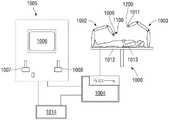
图3是根据本公开提供的机器人外科器械的示意图;3 is a schematic diagram of a robotic surgical instrument provided in accordance with the present disclosure;
图4是图1的钳的远侧端部部分的透视图,其中钳的末端执行器组合件的第一和第二钳口构件安置在间隔开的位置;FIG. 4 is a perspective view of the distal end portion of the forceps of FIG. 1 with first and second jaw members of the end effector assembly of the forceps disposed in spaced-apart locations;
图5A是图4的末端执行器组合件的第一钳口构件的仰视透视图;5A is a bottom perspective view of the first jaw member of the end effector assembly of FIG. 4;
图5B是图4的末端执行器组合件的第二钳口构件的俯视透视图;5B is a top perspective view of the second jaw member of the end effector assembly of FIG. 4;
图6A-6C是根据本公开提供的并且被配置成用于与图4的末端执行器组合件的第二钳口构件一起使用的热切割元件的各种配置的局部侧视横截面图;6A-6C are partial side cross-sectional views of various configurations of thermal cutting elements provided in accordance with the present disclosure and configured for use with the second jaw member of the end effector assembly of FIG. 4;
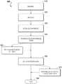
图7是示出制造根据本公开提供的热切割元件的方法的流程图;7 is a flow chart illustrating a method of manufacturing a thermal cutting element provided in accordance with the present disclosure;
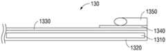
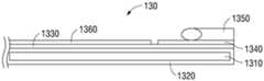
图8A是根据本公开提供的另一种热切割元件的侧视图;8A is a side view of another thermal cutting element provided in accordance with the present disclosure;
图8B是示出图8A的热切割元件在使用中向组织施加热能的侧视图;和Figure 8B is a side view showing the thermal cutting element of Figure 8A applying thermal energy to tissue in use; and
图9是根据本公开提供的末端执行器组合件的透视局部透视图,所述末端执行器组合件其中结合了图8A的热切割元件。9 is a perspective partial perspective view of an end effector assembly provided in accordance with the present disclosure incorporating the thermal cutting element of FIG. 8A therein.
具体实施方式Detailed ways
参考图1,示出了根据本公开提供的基于轴的电外科钳,其通常由附图标记10标识。省略了与本公开的理解没有密切关系的钳10的方面和特征,以避免在不必要的细节上模糊本公开的方面和特征。Referring to FIG. 1 , a shaft-based electrosurgical forceps provided in accordance with the present disclosure is shown, generally designated by the
钳10包括壳体20、手柄组合件30、触发器组合件60、旋转组合件70、第一启动开关80、第二启动开关90和末端执行器组合件100。钳10进一步包括具有配置成(直接或间接)啮合末端执行器组合件100的远侧端部部分14和(直接或间接)啮合壳体20的近侧端部部分16的轴12。钳10还包括将钳10连接到能量源(例如电外科发生器“G”)的缆线“C”。缆线“C”包括延伸穿过其中的电线(或多根电线)(未示出),其具有足够的长度以延伸穿过轴12,以便分别连接到末端执行器组合件100的钳口构件110、120的一个或两个组织处理表面114、124(参见图4),以向其提供能量。第一启动开关80联接到组织处理表面114、124(图4)和电外科发生器“G”,用于能够选择性地启动对钳口构件110、120的能量供应,用于处理例如烧灼、凝结/干燥和/或密封组织。第二启动开关90联接到钳口构件120的热切割元件130(图4)和电外科发生器“G”,用于能够选择性地启动对热切割元件150的能量供应,用于热切割组织。The
钳10的手柄组合件30包括固定手柄50和可移动手柄40。固定手柄50与壳体20整体相连,手柄40可相对于固定手柄50移动。手柄组合件30的可移动手柄40可操作地联接到驱动组合件(未示出),该驱动组合件一起机械地协作以使末端执行器组合件100的钳口构件110、120中的一个或两个围绕枢轴103在间隔开的位置和接近位置之间移动,从而将组织抓握在钳口构件110、120的组织处理表面114、124之间。如图1所示,可移动手柄40最初与固定手柄50间隔开,并且相应地,末端执行器组合件100的钳口构件110、120安置在间隔开的位置。可移动手柄40可从该初始位置按压到对应于钳口构件110、120的接近位置的按压位置。旋转组合件70包括旋转轮72,其可选择性地向任一方向旋转以相对于壳体20对应地旋转末端执行器组合件100。The
参考图2,示出了根据本公开提供的止血式电外科钳,其通常由附图标记210标识。省略了与本公开的理解没有密切关系的钳210的方面和特征,以避免在不必要的细节上模糊本公开的方面和特征。Referring to FIG. 2 , a hemostatic electrosurgical forceps provided in accordance with the present disclosure is shown, generally identified by
钳210包括两个细长轴构件212a、212b,每个细长轴构件分别具有近侧端部部分216a、216b和远侧端部部分214a、214b。钳210被配置成用于与类似于末端执行器组合件100(图4)的末端执行器组合件100'一起使用。更具体地说,末端执行器组合件100'包括附接到轴构件212a、212b的相应远侧端部部分214a、214b的第一钳口构件110'和第二钳口构件120'。钳口构件110'、120'围绕枢轴103'可枢转地连接。每个轴构件212a、212b包括安置在其近侧端部部分216a、216b处的手柄217a、217b。每个手柄217a、217b限定穿过其中的手指孔218a、218b,用于接收使用者的手指。如可以理解的,手指孔218a、218b便于轴构件212a、212b相对于彼此的移动,从而将钳口构件110'、120'从间隔开的位置枢转到接近位置,在间隔开的位置处,钳口构件110'、120'相对于彼此以间隔开的关系安置,在接近位置处,钳口构件110'、120'协作以将组织抓握在其间。The
钳210的轴构件212a、212b中的一个,例如轴构件212b,包括近侧轴连接器219,其被配置成将钳210连接到能量源,例如电外科发生器“G”(图1)。近侧轴连接器219将缆线“C”固定到钳210,使得使用者可以选择性地向钳口构件110'、120'供应能量以处理组织。更具体地说,提供第一启动开关280用于在轴构件212a、212b充分靠近时,例如,在经由轴构件212a启动第一启动开关280时,向钳口构件110'、120'供应能量以处理组织。安置在轴构件212a、212b中的任一个或两个上的第二启动开关290联接到末端执行器组合件100'的钳口构件110'、120'中的一个的热切割元件(未示出,类似于钳口构件120的热切割元件150(图4)),且联接到电外科发生器“G”,以能够选择性地启动向热切割元件供应能量,用于热切割组织。One of the
钳口构件110'、120'限定弯曲配置,其中每个钳口构件类似地横向弯曲离开末端执行器组合件100'的纵向轴线。然而,也考虑了其他合适的弯曲配置,包括朝向钳口构件110、120'中的一个(并因此远离另一个)的弯曲,具有相同平面的多个弯曲和/或不同平面内的多个弯曲。末端执行器组合件100(图1)的钳口构件110、120同样可以根据上文指出的任何配置或以任何其它合适的方式弯曲。The jaw members 110', 120' define a curved configuration wherein each jaw member is similarly curved laterally away from the longitudinal axis of the end effector assembly 100'. However, other suitable bend configurations are also contemplated, including bends towards one (and thus away from the other) of the
参考图3,示出了根据本公开提供的机器人外科器械,其通常由附图标记1000标识。省略了与本公开的理解没有密切关系的机器人外科器械1000的方面和特征,以避免在不必要的细节上模糊本公开的方面和特征。Referring to FIG. 3 , a robotic surgical instrument provided in accordance with the present disclosure is shown, generally identified by the
机器人外科器械1000包括多个机器人臂1002、1003;控制装置1004;以及与控制装置1004联接的操作控制台1005。操作控制台1005可以包括显示装置1006,该显示装置可以被特别设置成显示三维图像;以及手动输入装置1007、1008,外科医生通过手动输入装置1007、1008,能够在第一操作模式下远程操纵机器人臂1002、1003。机器人外科器械1000可以被配置成用于在躺在患者手术台1012上的患者1013上使用,以便以微创方式进行治疗。机器人外科器械1000还可以包括特别是联接到控制装置1004的数据库1014,其中存储例如来自患者1013的手术前数据和/或解剖图。The robotic
机器人臂1002、1003中的每一个可以包括通过接头连接的多个构件,和附接装置1009、1011,例如末端执行器组合件1100、1200可以分别附接到附接装置1009、1011。末端执行器组合件1100类似于末端执行器组合件100(图4A),但也考虑了其他合适的末端执行器组合件用于联接到附接装置1009上。末端执行器组合件1200可以是任何末端执行器组合件,例如内窥镜照相机、其他外科工具等。机器人臂1002、1003和末端执行器组合件1100、1200可以由连接到控制装置1004的电驱动器(例如,马达)驱动。控制装置1004(例如,计算机)可以被配置成具体地借助于计算机程序来启动马达,其方式为使得机器人臂1002、1003、它们的附接装置1009、1011以及末端执行器组合件1100、1200分别根据来自手动输入装置1007、1008的对应输入来执行所需的移动和/或功能。还可以配置控制装置1004,其方式为使得其调节机器人臂1002、1003和/或马达的移动。Each of the
转到图4-5B,如上所指出,末端执行器组合件100包括第一钳口构件110和第二钳口构件120。每个钳口构件110、120可以包括结构框架111、121,钳口壳体112、122,和限定其相应组织处理表面114、124的组织处理板113、123。替代地,钳口构件中的仅一个,例如钳口构件120,可以包括结构框架121、钳口壳体122和限定组织处理表面124的组织处理板123。在这类实施例中,例如钳口构件110的其他钳口构件可以形成为单个整体,例如一块导电材料充当结构框架111和钳口壳体112且限定组织处理表面114。在这类实施例中,钳口壳体112的外表面可以至少部分涂覆有绝缘材料或可以保持暴露。在实施例中,组织处理板113、123可以例如经由溅射沉积到钳口壳体112、122或安置在钳口壳体112、122内的钳口插件(未示出)上。替代地,组织处理板113、123可以预先形成并经由例如包覆成型、粘合、机械啮合等与钳口壳体112、122和/或安置在钳口壳体112、122内的钳口插件(未示出)啮合。Turning to FIGS. 4-5B , as noted above, the
特别参考图4和5A,如上所指出,钳口构件110可以与钳口构件120类似地配置,可以形成为单个整体,或者可以以任何其他合适的方式形成以便限定结构框架111和与钳口构件120的组织处理表面124相对的组织处理表面114。结构框架111包括近侧法兰部分116,钳口构件110围绕所述近侧法兰部分116可枢转地联接到钳口构件120。在基于轴或机器人实施例中,近侧法兰部分116可以进一步包括用于接收枢轴103的孔口117a和自其延伸的至少一个突起部117b,所述突起部117b被配置成用于接收在限定驱动组合件(未示出)的驱动套管内的孔口内,使得驱动套管的平移,例如响应于可移动手柄40(图1)的致动或机器人驱动,使钳口构件110在间隔开的位置与接近位置之间围绕枢轴103且相对于钳口构件120枢转。然而,也考虑了其他合适的驱动布置,例如,使用凸轮销和凸轮槽、螺杆驱动机构等。With particular reference to Figures 4 and 5A, as noted above,
不管钳口构件110的具体配置如何,钳口构件110可以包括沿着组织处理表面114的长度的至少一部分延伸的纵向延伸绝缘构件115。绝缘构件115可以横向居中于组织处理表面114上或可以相对于其偏移。此外,绝缘构件115可以安置(例如,沉积、涂覆等)在组织处理表面114上,可以定位在限定在组织处理表面114内的通道或凹槽内,或者可以限定任何其他合适的配置。此外,绝缘构件115可以与组织处理表面114基本上(在制造、材料和/或使用公差内)共面,可以从组织处理表面114突出,可以相对于组织处理表面114凹陷,或者可以包括相对于组织处理表面114共面、突出和/或凹陷的不同部分。绝缘构件115可以由例如陶瓷、聚对二甲苯、尼龙、PTFE或(一种或多种)其他合适的材料(包括绝缘和非绝缘材料的组合)形成。Regardless of the specific configuration of
参考图4和5B,如上所指出,钳口构件120可以包括结构框架121、钳口壳体122和限定其组织处理表面124的组织处理板123。钳口构件120进一步包括热切割元件130。结构框架121限定近侧法兰部分126和从近侧法兰部分126向远侧延伸的远侧主体部分(未示出)。近侧法兰部分126被分叉以限定一对间隔开的近侧法兰部分区段,它们将钳口构件110的近侧法兰111接收在其间并限定对准的孔口127,所述孔口127被配置成用于接收穿过其中的枢轴103,以将钳口构件110、120彼此可枢转地联接。4 and 5B, as noted above,
钳口构件120的钳口壳体122例如经由包覆成型、粘合、机械啮合等安置在结构框架121的远侧主体部分周围,并且例如经由包覆成型、粘合、机械啮合、沉积(例如经由溅射)等将组织处理板123支撑在其上。如上所指出,组织处理板123限定组织处理表面124。纵向延伸的狭槽125被限定穿过组织处理板123并且被定位成在接近位置与钳口构件110的绝缘构件115(图5A)相对。狭槽125可以延伸穿过钳口壳体122的至少一部分、钳口插件(如果提供的话)和/或钳口构件120的其他部件,以使得热切割元件130能够至少部分地接收在狭槽125内。The
更具体地说,热切割元件130安置在纵向延伸的狭槽125内,使得热切割元件130在接近位置与钳口构件110的绝缘构件115(图5A)相对。热切割元件130可以被配置成在接近位置接触绝缘构件115(图5A),以调节或促成处于接近位置的组织处理表面114、124之间的间隙距离的调节。替代地或另外,可以提供与钳口构件110和/或钳口构件120相关联的一个或多个止动构件(未示出)以调节处于接近位置的组织处理表面114、124之间的间隙距离。More specifically, the
热切割元件130可以被安置在狭槽125内的绝缘构件128包围,以将热切割元件与组织处理板123电隔离。替代地或另外,热切割元件130可以出于类似目的在其至少侧面上包括绝缘涂层。热切割元件130和绝缘构件128可以类似地或不同地与组织处理表面124基本上(在制造、材料和/或使用公差内)共面,可以从组织处理表面124突出,可以相对于组织处理表面124凹陷,或者可以包括相对于组织处理表面124共面、突出和/或凹陷的不同部分。
在末端执行器组合件100或其一部分是弯曲的实施例中,纵向延伸的狭槽125和热切割元件130可以类似地是弯曲的,例如,其中纵向延伸的狭槽125和热切割元件130(或其对应部分)相对地参考曲率弧(或多个弧)而不是纵向轴线来配置。因此,如本文所用的术语纵向、横向等不限于直线的配置,例如沿着直线的轴线,而是同样适用于弯曲配置,例如沿曲率弧。在这类弯曲配置中,钳口构件110(图5A)的绝缘构件115同样是弯曲的。In embodiments in which
一般参考图1-5B,组织处理板113、123由导电材料形成,例如,用于在其间传导电能以处理组织,但组织处理板113、123可以替代地被配置成将例如热、微波、光、超声波等的任何合适的能量传导穿过其间抓握的组织,用于进行基于能量的组织处理。如上所提及,组织处理板113、123联接到启动开关80和电外科发生器“G”(图1),使得能量可以选择性地供应到组织处理板113、123并在其间传导并穿过安置在钳口构件110、120之间的组织以处理组织,例如密封任一侧上并延伸跨过热切割元件130的组织。Referring generally to Figures 1-5B,
另一方面,热切割元件130被配置成连接到电外科发生器“G”(图1)和第二启动开关90,以能够选择性地启动对热切割元件130的能量供应,用于加热热切割元件130以热切割安置在钳口构件110、120之间的组织,例如,将密封组织切割成第一和第二密封组织部分。可替代地提供包括多模式开关、其他单独开关等的其他配置。On the other hand, the
参考图6A-6C,热切割元件130可以是任何合适的热切割元件,例如铝基板,其至少一部分经过等离子电解氧化(PEO)处理,并附有加热层,使得当施加AC电压后,热切割元件130被加热以热切割与其接触的组织。更具体地说,热切割元件130可以包括基板1310、包围基板1310的外表面的至少一部分的PEO涂层1320、以及安置在PEO涂层1320上的加热层1330。在实施例中,热切割元件130可以进一步包括安置在加热层1330上的第一和第二电触点1340(在图6B和6C中仅示出一个电触点),用于将第一和第二电引线1350连接到其上(在图6A-6C中仅示出一根电引线),但电引线1350可以替代地连接到加热层1330而不使用电触点(参见图6A)。另外或替代地,热切割元件130可以包括安置在加热层1330和/或PEO涂层1320的一部分上的绝缘层1360(图6C)。在实施例中,作为经PEO涂覆的基板的替代方案,可以利用陶瓷基板。6A-6C, the
转到图7,结合考图6A-6C,详细描述了制造热切割元件130的方法900。最初,在步骤910,制造基板1310。出于本文的目的,术语“制造”包括从例如第三方供应商或制造该部件的供应商处获得部件。此外,尽管在下文中必须按顺序进行描述,但在可行的范围内,方法900的各个步骤不需要按下面详述的顺序执行;还考虑了多个步骤的同时执行。Turning to FIG. 7 , a
关于在步骤910制造基板1310,基板1310可以由铝、钛、其合金、其组合或可以进行PEO阳极化的(一种或多种)其他合适的材料制成。在实施例中,多个基板1310一起制造,例如作为承载带上的渐进模冲压部分。在其他实施例中,每个基板1310可以单独制造,例如经由机械加工、铸造、锻造、精冲或任何其他合适的方法。为了简单起见,下面针对单个基板1310和热切割元件130详细描述方法900,但应理解方法900可以类似地应用于多个基板1310以形成多个热切割元件130。With regard to fabricating the
继续到步骤920,准备基板1310。准备基板1310可以包括脱脂和/或清洁,例如,使用任何合适的方法;去毛刺;断边;和/或表面修饰,例如滚揉、喷砂处理、化学蚀刻、电抛光等中的一种或多种。Continuing to step 920, the
一旦基板1310准备好,基板1310就在步骤930进行PEO阳极化。更具体地说,为了对基板1310进行PEO阳极化,基板1310被用作电化学浴中的阳极。也就是说,将基板1310浸没在冷电解液浴中,所述电解液由例如含有硅酸钠或硅酸钾的稀碱性溶液组成。基板1310连接到电能源以限定电化学浴中的一个电极,其中例如由不锈钢的惰性材料制成的对电极也电联接到电化学浴,从而例如形成浴本身的壁。例如在实施例中,在两个电极之间施加超过200V且至多700V的电势。电势可以是连续的或脉冲式直流电(DC)或交流电(AC)的脉冲。PEO涂层1320的所需最终厚度可以决定所施加的特定电压和/或基板1310保持在浴中的时间。Once the
与标准阳极化相比,对于PEO阳极化,施加了更高的电压电势。例如,在实施例中,例如关于铝的PEO阳极化,电压电势可以为至少200V且至多700V。这些高电压超过了正在生长的氧化膜的介电击穿电势并允许放电。这些放电导致在高温和高压条件下的局部等离子反应,其例如经由生长的氧化物的熔化、熔体流动、再固化、烧结和/或致密化,改变生长的氧化物。具体地说,氧化物部分地从无定形氧化铝转化为结晶形式,如硬度增加的刚玉(α-Al2O3)。For PEO anodization, a higher voltage potential was applied compared to standard anodization. For example, in embodiments, such as for PEO anodization of aluminum, the voltage potential may be at least 200V and at most 700V. These high voltages exceed the dielectric breakdown potential of the growing oxide film and allow discharge. These discharges result in localized plasma reactions under high temperature and high pressure conditions that alter the grown oxide, eg, via melting, melt flow, resolidification, sintering, and/or densification of the grown oxide. Specifically, the oxide is partially converted from amorphous alumina to a crystalline form, such as corundum (α-Al2O3) of increased hardness.
一旦在步骤930完成基板1310的PEO阳极化以在基板1310的至少一部分周围形成PEO涂层1320,就可以用水洗涤经涂覆的基板。另外或替代地,在实施例中,可以抛光经涂覆的基板以消除或减少由PEO过程引起的表面粗糙化。Once the PEO anodization of the
可以控制步骤930的PEO阳极化过程,使得涂层1320限定在实施例中约50微米至约150微米;在其他实施例中约75微米至约125微米;在再其他实施例中约90微米至约110微米;和在又其他实施例中约100微米的平均厚度。如本文所用的“约”考虑了材料、制造、测量、环境和其他对于特定应用通常可接受的公差,并且可以包括至少+/-10%的变化。The PEO anodization process of
如上文详述的PEO涂层1320的电绝缘特性为至少约10V/微米。因此,对于厚度为约100微米的PEO涂层1320,PEO涂层1320提供至少1000V的介电势垒。这允许PEO涂层1320承受高达1000℃的温度,并且与在不开裂的情况下不能承受高于约150℃的温度的标准阳极化相比是有利的。The electrical insulating properties of
一旦如上文详述地在基板1310周围形成PEO涂层1320,加热层1330就可以附连到经PEO涂覆的基板,如步骤940所指示。关于附连加热层1330,这可以经由如溅射的沉积工艺来完成,但也可以考虑其他附连加热层1330的方法,例如丝网印刷。这些方法是有利的,因为它们允许附连而不需要将基板1310加热到其熔点以上。加热层1330可以由例如镍铬合金、康泰尔(kanthal)、铂、其组合或满足所需的加热和电阻特征的(一种或多种)其他合适的金属(例如,正热系数(PTC)电阻加热材料)形成。Once the
更具体地说,溅射工艺可以包括将经涂覆的基板装载到荫罩固定件中并将加热层1330溅射到经涂覆的基板上以将加热元件电路附连到经PEO涂覆的基板上。More specifically, the sputtering process may include loading the coated substrate into a shadow mask holder and sputtering the
更具体地说,丝网印刷工艺可以包括将经涂覆的基板装载到丝网印刷固定件中并将加热层1330连同粘结剂一起丝网印刷到经涂覆的基板上。然后在约850℃至约1000℃下烧制所得物以烧掉粘结剂并将加热层1330烧结到经PEO涂覆的基板上,从而将加热元件电路附连到经PEO涂覆的基板上。More specifically, the screen printing process may include loading the coated substrate into a screen printing fixture and screen printing the
在实施例中,在步骤950,将电绝缘材料安置在加热层1330周围以形成绝缘层1360。绝缘层1360可以是二氧化硅和/或溅射到加热层1330上以提供氧化和/或流体进入保护以及电绝缘。替代地,绝缘层1360可以是玻璃和/或丝网印刷并烧制在加热层1330上以提供氧化和/或流体进入保护以及电绝缘。还考虑了其他合适的材料和/或附连方法。In an embodiment, at
如步骤960所指示,建立到加热层1330的电连接。在实施例中,电触点1340附连到加热层1330以用于将对应的电引线1350连接到其上。替代地,电引线1350可以连接到加热层1330而不使用电触点1340。As indicated by
在提供的实施例中,电触点1340可以由例如适合于促进电连接的材料(例如镍或铜)形成。电触点1340可以经由溅射,例如利用第二荫罩固定件施加在加热元件电路的端部部分处。在实施例中,电触点1340可以使用例如镍或其他合适的可电镀金属的电镀来加厚。作为溅射的替代方案,呈电接触垫形式的电触点1340可以丝网印刷并烧制到加热元件电路的端部部分上。In the provided embodiment, the
电引线1350经由溅射直接或间接连接到电触点1340或加热元件电路的端部部分(在未提供电触点1340的实施例中)。电引线1350可以使用例如弹簧夹2370(参见图9)的机械连接器或例如电阻焊接、激光焊接、球焊、电镀、铜焊、钎焊、使用导电粘合剂胶等的其他合适的附接方法来连接。Electrical leads 1350 are connected directly or indirectly via sputtering to
如步骤970所指示,形成的热切割元件130最终可以集成、附接或以其他方式结合到例如末端执行器组合件100、2100(分别图4和9)的外科末端执行器组合件中。否则或之后,方法在980结束。As indicated at
参考图8A和8B,并首先参考图8A,示出了根据本公开的热切割元件230的实施例,例如,其利用上文详述的方法900(图7)制造或以任何其他合适的方式制造。热切割元件230包括:基板2310;安置在基板2310周围的PEO涂层2320;加热层2330,其安置在PEO涂层2320上以形成加热元件电路,其包括第一端部部分2331和第二端部部分2332;以及第一和第二触点2340,其电联接到加热层2330的相应第一端部部分2331和第二端部部分2332。热切割元件230限定细长主体232、从细长主体232的近侧端部部分延伸的近侧连接法兰234、以及从细长主体232例如从细长主体232的中心或远侧端部部分延伸的一个或多个附接法兰236。加热层2330的第一端部部分2331和第二端部部分2332安置在近侧连接法兰234处。加热层2330限定连续电路迹线,其包括分别从第一端部部分2331和第二端部部分2332沿着细长主体232向远侧延伸到或邻近细长主体232的远侧端部部分的第一和第二间隔开的区段,其中第一和第二区段经由加热层2330的连接器区段相互连接。Referring to Figures 8A and 8B, and initially to Figure 8A, there is shown an embodiment of a
第一和第二触点2340在近侧连接法兰234处分别附连到加热层2330的第一部部分2331和第二端部部分2332,以使得电引线能够连接到其上,用于向其施加AC电压以加热热切割元件230。在实施例中,近侧连接法兰234相对于细长主体232的纵向轴线正交地延伸,但还考虑了其他配置。The first and
附接法兰236限定孔口237,所述孔口237被配置成便于热切割元件230啮合在钳口构件例如钳口构件2120(图9)或外科末端执行器组合件的其他合适部件内。在实施例中,附接法兰236相对于细长主体232的纵向轴线正交地延伸,但还考虑了其他配置。The
图8B示出了使用中的热切割元件230,其中组织“T”与热切割元件230接触并且AC电压施加在第一和第二触点2340两端上,从而加热热切割元件230。方向箭头指示热梯度,由此,由于热切割元件230的配置,热量从热切割元件230的不与组织“T”接触的部分传导到与组织“T”接触的那些部分。这便于加热和控制热切割元件230的与组织“T”接触的部分的温度,从而便于控制组织“T”的切割。8B shows
转到图9,示出热切割元件230(图8A和8B)结合到类似于末端执行器组合件100(图4)的末端执行器组合件2100中。末端执行器组合件2100一般包括第一钳口构件2110和第二钳口构件2120,其中的至少一个可相对于另一个在间隔开的位置和接近位置之间移动。每个钳口构件2110、2120包括结构框架2111、2121、钳口壳体2112、2122和限定组织处理表面2114、2124的组织处理板2113、2123。末端执行器组合件2100可以进一步包括如上文详述的末端执行器组合件100(图4)的任何特征并且可以以类似的方式操作。因此,为了简洁起见,下面仅详细描述不同之处。Turning to Figure 9, thermal cutting elements 230 (Figures 8A and 8B) are shown incorporated into an
钳口构件2120包括安置在其中的第一和第二弹簧夹2370以及连接到相应第一和第二弹簧夹2370的第一和第二电引线2350。热切割元件230座置在限定在钳口构件2120内的纵向延伸狭槽2125内,使得相应第一和第二弹簧夹2370与近侧连接法兰234啮合并被偏置以维持与电触点2340的电接触,从而将电引线2350与加热层2330电连接。热切割元件230的细长主体232沿着钳口构件210纵向延伸并且定位成与组织处理表面2124齐平、相对于组织处理表面2124凹进或从组织处理表面2124突出。细长主体232可以在组织处理板2123和/或钳口构件2120的远侧端部之前终止、可以延伸到组织处理板2123和/或钳口构件2120的远侧端部或可以延伸超过组织处理板2123和/或钳口构件2120的远侧端部。The
热切割元件230可以经由内部钳口插件(未示出)和/或钳口壳体2122围绕结构框架2121包覆成型而固定在钳口构件2120内。关于包覆成型钳口壳体2122(或内部钳口插件),附接法兰236的孔口237使包得覆成型材料能够流过其中,从而便于牢固啮合。近侧连接法兰234与弹簧夹2370的啮合还便于将热切割元件230机械固定在适当位置。
虽然在附图中已经示出了本公开的几个实施例,但并不意味着本公开局限于此,因为意图是使本公开的范围与本领域所允许的一样宽,并且同样地阅读说明书。因此,上文描述不应解释为限制性的,而仅仅是作为特定实施例的例证。所属领域的技术人员将设想在本文所附权利要求书的范围和精神内的其它修改。Although several embodiments of the present disclosure have been shown in the drawings, it is not intended that the disclosure be limited thereto, for the intention is to extend the scope of the disclosure as broadly as the art allows, and the specification should be read as such . Therefore, the above description should not be construed as limiting, but merely as exemplifications of particular embodiments. Those skilled in the art will envision other modifications within the scope and spirit of the claims appended hereto.
Claims (30)
Applications Claiming Priority (5)
| Application Number | Priority Date | Filing Date | Title |
|---|---|---|---|
| US201962952234P | 2019-12-21 | 2019-12-21 | |
| US201962952232P | 2019-12-21 | 2019-12-21 | |
| US62/952,234 | 2019-12-21 | ||
| US62/952,232 | 2019-12-21 | ||
| PCT/US2020/061998WO2021126490A1 (en) | 2019-12-21 | 2020-11-24 | Thermal cutting elements, electrosurgical instruments including thermal cutting elements, and methods of manufacturing |
Publications (1)
| Publication Number | Publication Date |
|---|---|
| CN114845650Atrue CN114845650A (en) | 2022-08-02 |
Family
ID=73854950
Family Applications (1)
| Application Number | Title | Priority Date | Filing Date |
|---|---|---|---|
| CN202080088545.6APendingCN114845650A (en) | 2019-12-21 | 2020-11-24 | Thermal cutting element, electrosurgical instrument including thermal cutting element, and method of manufacture |
Country Status (5)
| Country | Link |
|---|---|
| US (3) | US12049706B2 (en) |
| EP (1) | EP4076239B1 (en) |
| JP (1) | JP2023507557A (en) |
| CN (1) | CN114845650A (en) |
| WO (1) | WO2021126490A1 (en) |
Families Citing this family (5)
| Publication number | Priority date | Publication date | Assignee | Title |
|---|---|---|---|---|
| US20230149065A1 (en)* | 2021-11-15 | 2023-05-18 | Covidien Lp | Vessel sealer with plasma blade dissection electrode |
| JP2025502030A (en) | 2022-01-14 | 2025-01-24 | コヴィディエン リミテッド パートナーシップ | Multifunctional ultrasonic blade and surgical instrument incorporating same |
| EP4498952A1 (en)* | 2022-03-31 | 2025-02-05 | Covidien LP | Thermal cutting assembly with conductive bridge |
| WO2023187737A1 (en)* | 2022-03-31 | 2023-10-05 | Covidien Lp | Thermal cutting assembly for mechanical engagement within jaw member |
| EP4498956A1 (en)* | 2022-03-31 | 2025-02-05 | Covidien LP | Curved thermal cutter assembly and method for manufacturing same |
Citations (5)
| Publication number | Priority date | Publication date | Assignee | Title |
|---|---|---|---|---|
| US20080257585A1 (en)* | 2005-01-15 | 2008-10-23 | Thermastrate Limited | Electrical Power Substrate |
| CN101507628A (en)* | 2008-02-14 | 2009-08-19 | 伊西康内外科公司 | Surgical cutting and fastening instrument having RF electrodes |
| CN102271607A (en)* | 2008-11-11 | 2011-12-07 | 施菲姆德有限责任公司 | Small Profile Electrode Assembly |
| CN103826694A (en)* | 2011-09-30 | 2014-05-28 | 柯惠有限合伙公司 | Energy transfer device and method of use |
| US20180206907A1 (en)* | 2001-04-06 | 2018-07-26 | Covidien Ag | Vessel sealer and divider |
Family Cites Families (82)
| Publication number | Priority date | Publication date | Assignee | Title |
|---|---|---|---|---|
| US2068721A (en) | 1932-11-18 | 1937-01-26 | Wappler Frederick Charles | Method for electrosurgical severance of adhesions |
| US4091813A (en) | 1975-03-14 | 1978-05-30 | Robert F. Shaw | Surgical instrument having self-regulated electrical proximity heating of its cutting edge and method of using the same |
| US5389098A (en) | 1992-05-19 | 1995-02-14 | Olympus Optical Co., Ltd. | Surgical device for stapling and/or fastening body tissues |
| US5807393A (en) | 1992-12-22 | 1998-09-15 | Ethicon Endo-Surgery, Inc. | Surgical tissue treating device with locking mechanism |
| US5403312A (en) | 1993-07-22 | 1995-04-04 | Ethicon, Inc. | Electrosurgical hemostatic device |
| US5693051A (en) | 1993-07-22 | 1997-12-02 | Ethicon Endo-Surgery, Inc. | Electrosurgical hemostatic device with adaptive electrodes |
| US5810811A (en) | 1993-07-22 | 1998-09-22 | Ethicon Endo-Surgery, Inc. | Electrosurgical hemostatic device |
| US5465895A (en) | 1994-02-03 | 1995-11-14 | Ethicon Endo-Surgery, Inc. | Surgical stapler instrument |
| US5637111A (en)* | 1995-06-06 | 1997-06-10 | Conmed Corporation | Bipolar electrosurgical instrument with desiccation feature |
| US5827271A (en) | 1995-09-19 | 1998-10-27 | Valleylab | Energy delivery system for vessel sealing |
| US6626901B1 (en) | 1997-03-05 | 2003-09-30 | The Trustees Of Columbia University In The City Of New York | Electrothermal instrument for sealing and joining or cutting tissue |
| US5911719A (en) | 1997-06-05 | 1999-06-15 | Eggers; Philip E. | Resistively heating cutting and coagulating surgical instrument |
| US6096037A (en) | 1997-07-29 | 2000-08-01 | Medtronic, Inc. | Tissue sealing electrosurgery device and methods of sealing tissue |
| US6402747B1 (en) | 1997-07-21 | 2002-06-11 | Sherwood Services Ag | Handswitch cord and circuit |
| US6273887B1 (en) | 1998-01-23 | 2001-08-14 | Olympus Optical Co., Ltd. | High-frequency treatment tool |
| US6736813B2 (en) | 1998-01-23 | 2004-05-18 | Olympus Optical Co., Ltd. | High-frequency treatment tool |
| US6086586A (en) | 1998-09-14 | 2000-07-11 | Enable Medical Corporation | Bipolar tissue grasping apparatus and tissue welding method |
| US7364577B2 (en) | 2002-02-11 | 2008-04-29 | Sherwood Services Ag | Vessel sealing system |
| US6953461B2 (en) | 2002-05-16 | 2005-10-11 | Tissuelink Medical, Inc. | Fluid-assisted medical devices, systems and methods |
| US20020107514A1 (en) | 2000-04-27 | 2002-08-08 | Hooven Michael D. | Transmural ablation device with parallel jaws |
| US6929641B2 (en) | 2001-08-27 | 2005-08-16 | Gyrus Medical Limited | Electrosurgical system |
| US6808525B2 (en) | 2001-08-27 | 2004-10-26 | Gyrus Medical, Inc. | Bipolar electrosurgical hook probe for cutting and coagulating tissue |
| US6802843B2 (en) | 2001-09-13 | 2004-10-12 | Csaba Truckai | Electrosurgical working end with resistive gradient electrodes |
| US7070597B2 (en) | 2001-10-18 | 2006-07-04 | Surgrx, Inc. | Electrosurgical working end for controlled energy delivery |
| US7354440B2 (en) | 2001-10-22 | 2008-04-08 | Surgrx, Inc. | Electrosurgical instrument and method of use |
| US7083619B2 (en) | 2001-10-22 | 2006-08-01 | Surgrx, Inc. | Electrosurgical instrument and method of use |
| US7125409B2 (en) | 2001-10-22 | 2006-10-24 | Surgrx, Inc. | Electrosurgical working end for controlled energy delivery |
| US6602252B2 (en) | 2002-01-03 | 2003-08-05 | Starion Instruments Corporation | Combined dissecting, cauterizing, and stapling device |
| AU2003205316A1 (en) | 2002-01-22 | 2003-09-02 | Sciogen Llc | Electrosurgical instrument and method of use |
| US7033356B2 (en) | 2002-07-02 | 2006-04-25 | Gyrus Medical, Inc. | Bipolar electrosurgical instrument for cutting desiccating and sealing tissue |
| US7931649B2 (en) | 2002-10-04 | 2011-04-26 | Tyco Healthcare Group Lp | Vessel sealing instrument with electrical cutting mechanism |
| US7270664B2 (en) | 2002-10-04 | 2007-09-18 | Sherwood Services Ag | Vessel sealing instrument with electrical cutting mechanism |
| US7276068B2 (en) | 2002-10-04 | 2007-10-02 | Sherwood Services Ag | Vessel sealing instrument with electrical cutting mechanism |
| EP1603474B1 (en) | 2003-02-14 | 2013-09-11 | The Board Of Trustees Of The Leland Stanford Junior University | Electrosurgical system with uniformly enhanced electric field and minimal collateral damage |
| US7169146B2 (en) | 2003-02-14 | 2007-01-30 | Surgrx, Inc. | Electrosurgical probe and method of use |
| US7326202B2 (en) | 2003-03-07 | 2008-02-05 | Starion Instruments Corporation | Tubular resistance heater with electrically insulating high thermal conductivity core for use in a tissue welding device |
| US7011656B2 (en) | 2003-11-14 | 2006-03-14 | Starion Instruments Corporation | Thermal cautery devices with improved heating profiles |
| GB2408936B (en) | 2003-12-09 | 2007-07-18 | Gyrus Group Plc | A surgical instrument |
| US7329255B2 (en) | 2003-12-23 | 2008-02-12 | Starion Instruments Corporation | System for regulating heating in a tissue sealing and cutting device |
| US7204835B2 (en) | 2004-02-02 | 2007-04-17 | Gyrus Medical, Inc. | Surgical instrument |
| DE102004031927A1 (en) | 2004-06-23 | 2006-01-19 | Aesculap Ag & Co. Kg | Surgical instrument |
| US7686827B2 (en) | 2004-10-21 | 2010-03-30 | Covidien Ag | Magnetic closure mechanism for hemostat |
| US7918848B2 (en) | 2005-03-25 | 2011-04-05 | Maquet Cardiovascular, Llc | Tissue welding and cutting apparatus and method |
| US8197472B2 (en) | 2005-03-25 | 2012-06-12 | Maquet Cardiovascular, Llc | Tissue welding and cutting apparatus and method |
| US8034051B2 (en) | 2005-07-15 | 2011-10-11 | Atricure, Inc. | Ablation device with sensor |
| US7815641B2 (en) | 2006-01-25 | 2010-10-19 | The Regents Of The University Of Michigan | Surgical instrument and method for use thereof |
| US20070265616A1 (en) | 2006-05-10 | 2007-11-15 | Sherwood Services Ag | Vessel sealing instrument with optimized power density |
| US7419490B2 (en) | 2006-07-27 | 2008-09-02 | Applied Medical Resources Corporation | Bipolar electrosurgical scissors |
| US8597297B2 (en) | 2006-08-29 | 2013-12-03 | Covidien Ag | Vessel sealing instrument with multiple electrode configurations |
| WO2008045184A1 (en) | 2006-10-05 | 2008-04-17 | Boston Scientific Limited | Polymer-free coatings for medical devices formed by plasma electrolytic deposition |
| US9192427B2 (en) | 2008-03-11 | 2015-11-24 | Covidien Lp | Bipolar cutting end effector |
| GB0804688D0 (en) | 2008-03-13 | 2008-04-16 | Gyrus Group Plc | Surgical instrument |
| ES2442241T3 (en) | 2008-03-31 | 2014-02-10 | Applied Medical Resources Corporation | Electrosurgical system with a switching mechanism |
| US9402679B2 (en) | 2008-05-27 | 2016-08-02 | Maquet Cardiovascular Llc | Surgical instrument and method |
| US9265556B2 (en) | 2009-04-17 | 2016-02-23 | Domain Surgical, Inc. | Thermally adjustable surgical tool, balloon catheters and sculpting of biologic materials |
| US9131977B2 (en) | 2009-04-17 | 2015-09-15 | Domain Surgical, Inc. | Layered ferromagnetic coated conductor thermal surgical tool |
| US9107666B2 (en) | 2009-04-17 | 2015-08-18 | Domain Surgical, Inc. | Thermal resecting loop |
| US9730749B2 (en) | 2009-04-17 | 2017-08-15 | Domain Surgical, Inc. | Surgical scalpel with inductively heated regions |
| US8187273B2 (en) | 2009-05-07 | 2012-05-29 | Tyco Healthcare Group Lp | Apparatus, system, and method for performing an electrosurgical procedure |
| US9955858B2 (en) | 2009-08-21 | 2018-05-01 | Maquet Cardiovascular Llc | Surgical instrument and method for use |
| US9050093B2 (en) | 2009-10-09 | 2015-06-09 | Ethicon Endo-Surgery, Inc. | Surgical generator for ultrasonic and electrosurgical devices |
| US8491626B2 (en) | 2010-06-02 | 2013-07-23 | Covidien Lp | Apparatus for performing an electrosurgical procedure |
| US9005199B2 (en) | 2010-06-10 | 2015-04-14 | Ethicon Endo-Surgery, Inc. | Heat management configurations for controlling heat dissipation from electrosurgical instruments |
| US8636730B2 (en) | 2010-07-12 | 2014-01-28 | Covidien Lp | Polarity control of electrosurgical generator |
| US8734445B2 (en) | 2010-09-07 | 2014-05-27 | Covidien Lp | Electrosurgical instrument with sealing and dissection modes and related methods of use |
| US9039694B2 (en) | 2010-10-22 | 2015-05-26 | Just Right Surgical, Llc | RF generator system for surgical vessel sealing |
| GB2489925B (en) | 2011-04-07 | 2018-09-12 | Gyrus Medical Ltd | Electrosurgical generator |
| US8932279B2 (en) | 2011-04-08 | 2015-01-13 | Domain Surgical, Inc. | System and method for cooling of a heated surgical instrument and/or surgical site and treating tissue |
| EP2704657A4 (en) | 2011-04-08 | 2014-12-31 | Domain Surgical Inc | IMPEDANCE ADAPTATION CIRCUIT |
| JP2015506729A (en) | 2011-12-06 | 2015-03-05 | ドメイン・サージカル,インコーポレーテッド | System and method for controlling power supply to a surgical instrument |
| US9084606B2 (en) | 2012-06-01 | 2015-07-21 | Megadyne Medical Products, Inc. | Electrosurgical scissors |
| US20140135804A1 (en) | 2012-11-15 | 2014-05-15 | Ethicon Endo-Surgery, Inc. | Ultrasonic and electrosurgical devices |
| US9050100B2 (en) | 2012-12-10 | 2015-06-09 | Ethicon Endo-Surgery, Inc. | Surgical instrument with feedback at end effector |
| JP5988868B2 (en)* | 2012-12-27 | 2016-09-07 | オリンパス株式会社 | Therapeutic treatment device |
| US20140194875A1 (en) | 2013-01-10 | 2014-07-10 | Covidien Lp | Surgical forceps |
| CN106456236B (en) | 2014-05-12 | 2019-10-29 | 捷锐士阿希迈公司(以奥林巴斯美国外科技术名义) | Resistance Heated Electrosurgical Instruments |
| US9931157B2 (en) | 2014-09-15 | 2018-04-03 | Ethicon Llc | Methods and devices for creating thermal zones within an electrosurgical instrument |
| DE112015006208B4 (en) | 2015-02-23 | 2022-05-25 | Hitachi High-Tech Corporation | ION GUIDE AND MASS SPECTROMETER USING THEM |
| US10987159B2 (en)* | 2015-08-26 | 2021-04-27 | Covidien Lp | Electrosurgical end effector assemblies and electrosurgical forceps configured to reduce thermal spread |
| CN108430350B (en) | 2016-01-11 | 2021-06-08 | 捷锐士阿希迈公司(以奥林巴斯美国外科技术名义) | Clamps with Tissue Stops |
| CN109922749B (en) | 2016-11-09 | 2021-10-12 | 奥林巴斯株式会社 | Medical device |
| US11013552B2 (en) | 2017-06-28 | 2021-05-25 | Cilag Gmbh International | Electrosurgical cartridge for use in thin profile surgical cutting and stapling instrument |
- 2020
- 2020-11-23USUS17/102,220patent/US12049706B2/enactiveActive
- 2020-11-23USUS17/102,315patent/US11365490B2/enactiveActive
- 2020-11-24WOPCT/US2020/061998patent/WO2021126490A1/ennot_activeCeased
- 2020-11-24CNCN202080088545.6Apatent/CN114845650A/enactivePending
- 2020-11-24EPEP20825358.3Apatent/EP4076239B1/enactiveActive
- 2020-11-24JPJP2022532068Apatent/JP2023507557A/enactivePending
- 2024
- 2024-07-03USUS18/762,956patent/US20240360581A1/enactivePending
Patent Citations (5)
| Publication number | Priority date | Publication date | Assignee | Title |
|---|---|---|---|---|
| US20180206907A1 (en)* | 2001-04-06 | 2018-07-26 | Covidien Ag | Vessel sealer and divider |
| US20080257585A1 (en)* | 2005-01-15 | 2008-10-23 | Thermastrate Limited | Electrical Power Substrate |
| CN101507628A (en)* | 2008-02-14 | 2009-08-19 | 伊西康内外科公司 | Surgical cutting and fastening instrument having RF electrodes |
| CN102271607A (en)* | 2008-11-11 | 2011-12-07 | 施菲姆德有限责任公司 | Small Profile Electrode Assembly |
| CN103826694A (en)* | 2011-09-30 | 2014-05-28 | 柯惠有限合伙公司 | Energy transfer device and method of use |
Also Published As
| Publication number | Publication date |
|---|---|
| JP2023507557A (en) | 2023-02-24 |
| US11365490B2 (en) | 2022-06-21 |
| EP4076239B1 (en) | 2024-01-03 |
| US12049706B2 (en) | 2024-07-30 |
| WO2021126490A1 (en) | 2021-06-24 |
| EP4076239A1 (en) | 2022-10-26 |
| US20210186587A1 (en) | 2021-06-24 |
| US20210189583A1 (en) | 2021-06-24 |
| US20240360581A1 (en) | 2024-10-31 |
Similar Documents
| Publication | Publication Date | Title |
|---|---|---|
| CN114845650A (en) | Thermal cutting element, electrosurgical instrument including thermal cutting element, and method of manufacture | |
| AU2001271688B2 (en) | Cooled electrosurgical forceps | |
| JP2020515334A (en) | Area ratio of patterned coating on RF electrode to reduce sticking | |
| EP3769709B1 (en) | Electrosurgical forceps including thermal cutting element | |
| EP2011447B1 (en) | Electro-surgical bipolar forceps | |
| CN101657166A (en) | non-stick bipolar forceps | |
| AU2001271688A1 (en) | Cooled electrosurgical forceps | |
| US20230285070A1 (en) | End effector assembly with thin seal plates | |
| US20240108393A1 (en) | Thermal cutting elements for electrosurgical instruments and electrosurgical instruments and systems incorporating the same | |
| CN116115326A (en) | Vascular sealer with plasma blade dissection electrode | |
| US20250221756A1 (en) | Thermal cutting assembly with conductive bridge | |
| US20250221758A1 (en) | Curved thermal cutter assembly and method for manufacturing same | |
| US20250235257A1 (en) | High temperature spacer for jaw member and method for manufacturing same | |
| US20230285064A1 (en) | Electrosurgical instruments, systems, and methods including use of thermal cutting elements | |
| US20230285065A1 (en) | Electrosurgical instruments including thermal cutting elements | |
| WO2023187737A1 (en) | Thermal cutting assembly for mechanical engagement within jaw member | |
| US20230240740A1 (en) | Thermal elements for surgical instruments and surgical instruments incorporating the same | |
| WO2024150189A1 (en) | Thermal heating assembly for a seal plate | |
| CN118647326A (en) | Thermal element for surgical instrument and surgical instrument including thermal element | |
| WO2024226648A1 (en) | Tissue treating electrodes for surgical instruments and surgical instruments incorporating the same | |
| CN117355272A (en) | Open dissection using sealed instruments |
Legal Events
| Date | Code | Title | Description |
|---|---|---|---|
| PB01 | Publication | ||
| PB01 | Publication | ||
| SE01 | Entry into force of request for substantive examination | ||
| SE01 | Entry into force of request for substantive examination |