CN114843777A - Millimeter Wave Broadband Beam Scanning Antenna Array - Google Patents
Millimeter Wave Broadband Beam Scanning Antenna ArrayDownload PDFInfo
- Publication number
- CN114843777A CN114843777ACN202210536739.9ACN202210536739ACN114843777ACN 114843777 ACN114843777 ACN 114843777ACN 202210536739 ACN202210536739 ACN 202210536739ACN 114843777 ACN114843777 ACN 114843777A
- Authority
- CN
- China
- Prior art keywords
- vivaldi
- metal
- millimeter
- beam scanning
- mode
- Prior art date
- Legal status (The legal status is an assumption and is not a legal conclusion. Google has not performed a legal analysis and makes no representation as to the accuracy of the status listed.)
- Pending
Links
Images


Classifications
- H—ELECTRICITY
- H01—ELECTRIC ELEMENTS
- H01Q—ANTENNAS, i.e. RADIO AERIALS
- H01Q1/00—Details of, or arrangements associated with, antennas
- H01Q1/52—Means for reducing coupling between antennas; Means for reducing coupling between an antenna and another structure
- H01Q1/521—Means for reducing coupling between antennas; Means for reducing coupling between an antenna and another structure reducing the coupling between adjacent antennas
- H01Q1/523—Means for reducing coupling between antennas; Means for reducing coupling between an antenna and another structure reducing the coupling between adjacent antennas between antennas of an array
- H—ELECTRICITY
- H01—ELECTRIC ELEMENTS
- H01Q—ANTENNAS, i.e. RADIO AERIALS
- H01Q21/00—Antenna arrays or systems
Landscapes
- Variable-Direction Aerials And Aerial Arrays (AREA)
Abstract
Translated fromChinese
Description
Translated fromChinese技术领域technical field
本申请涉及无线通信技术领域,尤其涉及毫米波宽带波束扫描天线阵列。The present application relates to the field of wireless communication technologies, and in particular, to a millimeter-wave broadband beam scanning antenna array.
背景技术Background technique
伴随着第五代移动通信技术(5th generation mobile networks,5G)的相关应用不断落地,将5G应用于毫米波频段以利用其丰富的频谱资源来缓解低频段拥堵的压力成为了业界共识。然而,毫米波频段的信号传输往往面临着较高的损耗,与此同时,在室外通信中,需要解决定点与移动目标间的稳定通信问题,因此,具有高增益的宽带波束扫描天线设计对解决以上问题具有极大价值。毫米波频段波长更短,因此毫米波天线整体尺寸更小,而波束扫描天线的阵元之间往往存在互耦,其会影响天线的波束扫描性能,因此,如何兼顾小型化和宽角扫描性能是毫米波波束扫描天线亟待解决的问题。With the continuous application of 5th generation mobile networks (5G), it has become an industry consensus to apply 5G to the millimeter-wave frequency band to use its abundant spectrum resources to relieve the pressure of low-frequency congestion. However, the signal transmission in the millimeter wave frequency band often faces high losses. At the same time, in outdoor communication, it is necessary to solve the problem of stable communication between fixed points and moving targets. Therefore, the design of broadband beam scanning antennas with high gain The above questions are of great value. The wavelength of the millimeter-wave band is shorter, so the overall size of the millimeter-wave antenna is smaller, and there is often mutual coupling between the elements of the beam scanning antenna, which will affect the beam scanning performance of the antenna. Therefore, how to balance miniaturization and wide-angle scanning performance It is an urgent problem to be solved for the millimeter-wave beam scanning antenna.
发明内容SUMMARY OF THE INVENTION
鉴于此,本申请实施例提供了毫米波宽带波束扫描天线阵列,以消除或改善现有技术中存在的一个或更多个缺陷。In view of this, embodiments of the present application provide a millimeter-wave broadband beam scanning antenna array to eliminate or improve one or more defects existing in the prior art.
本申请的一个方面提供了一种毫米波宽带波束扫描天线阵列,包括:多个采用半模毫米波宽带波束扫描天线单元的天线阵元,以及,用于隔离各个所述天线阵元之间能量的隔离组件;One aspect of the present application provides a millimeter-wave broadband beam scanning antenna array, comprising: a plurality of antenna elements using a half-mode millimeter-wave broadband beam scanning antenna unit, and for isolating energy between the antenna elements the isolation components;
各个所述天线阵元依次相接且同向固定设置在一金属介质组板的一侧面板上,且所述隔离组件设置在该金属介质组板中,所述金属介质组板的另一侧面板上设有同轴馈电单元。Each of the antenna array elements is connected in sequence and fixedly arranged on one side panel of a metal dielectric board, and the isolation components are arranged in the metal dielectric board, and the other side of the metal dielectric board There is a coaxial feed unit on the panel.
在本申请的一些实施例中,所述半模毫米波宽带波束扫描天线单元为半模Vivaldi天线单元。In some embodiments of the present application, the half-mode millimeter-wave broadband beam scanning antenna unit is a half-mode Vivaldi antenna unit.
在本申请的一些实施例中,所述半模Vivaldi天线单元包括:半个Vivaldi辐射壁和一个垂直金属壁,其中,所述半个Vivaldi辐射壁为自Vivaldi天线的中心线处切分得到的部件;In some embodiments of the present application, the half-mode Vivaldi antenna unit includes: a half Vivaldi radiating wall and a vertical metal wall, wherein the half Vivaldi radiating wall is obtained by cutting from the center line of the Vivaldi antenna part;
所述半个Vivaldi辐射壁和所述垂直金属壁的底部均固定设置在所述金属介质组板上;且该半个Vivaldi辐射壁和所述垂直金属壁之间形成有辐射缝隙。The bottoms of the half Vivaldi radiating wall and the vertical metal wall are fixedly arranged on the metal dielectric plate; and a radiation gap is formed between the half Vivaldi radiating wall and the vertical metal wall.
在本申请的一些实施例中,所述金属介质组板包括:In some embodiments of the present application, the metal dielectric board includes:
介质基板、设置在该介质基板一侧面板的第一金属板以及设置在该介质基板另一侧面板的第二金属板;a dielectric substrate, a first metal plate disposed on one side panel of the dielectric substrate, and a second metal plate disposed on the other side panel of the dielectric substrate;
各个所述半个Vivaldi辐射壁和所述垂直金属壁均固定设置在所述第一金属板上,所述同轴馈电单元固定设置在所述第二金属板上,且该同轴馈电单元的内管延伸并贯穿所述介质基板。Each half of the Vivaldi radiating wall and the vertical metal wall are fixedly arranged on the first metal plate, the coaxial feeding unit is fixedly arranged on the second metal plate, and the coaxial feeding unit is fixedly arranged on the second metal plate. The inner tube of the unit extends through the dielectric substrate.
在本申请的一些实施例中,所述隔离组件包括:设置在所述介质基板内的多列金属隔离单元;In some embodiments of the present application, the isolation assembly includes: a plurality of columns of metal isolation units disposed in the dielectric substrate;
各列所述金属隔离单元分别与所述半模Vivaldi天线单元的边缘对应设置,其中,所述半模Vivaldi天线单元的边缘包括:所述半个Vivaldi辐射壁底部的远离与其属于同一半模Vivaldi天线单元的所述垂直金属壁的一侧边缘,以及,所述垂直金属壁底部的远离与其属于同一半模Vivaldi天线单元的所述半个Vivaldi辐射壁的一侧边缘。The metal isolation units in each row are respectively disposed corresponding to the edge of the half-mode Vivaldi antenna unit, wherein the edge of the half-mode Vivaldi antenna unit includes: the bottom of the half-Vivaldi radiating wall is far from the bottom of the half-mode Vivaldi radiating wall and belongs to the same half-mode Vivaldi. One side edge of the vertical metal wall of the antenna unit, and the one side edge of the bottom of the vertical metal wall far away from the half Vivaldi radiating wall that belongs to the same half-mode Vivaldi antenna unit.
在本申请的一些实施例中,所述金属隔离单元包括:多个金属隔离通孔;In some embodiments of the present application, the metal isolation unit includes: a plurality of metal isolation vias;
各个所述金属隔离通孔均在所述金属介质组板中形成,且在垂直于所述金属介质组板的板面的方向延伸。Each of the metal isolation through holes is formed in the metal dielectric board and extends in a direction perpendicular to the board surface of the metal dielectric board.
在本申请的一些实施例中,在相邻的两个所述半模Vivaldi天线单元中,一个所述半模Vivaldi天线单元中的所述半个Vivaldi辐射壁和另一个所述半模Vivaldi天线单元中的所述垂直金属壁之间固定连接。In some embodiments of the present application, in two adjacent half-mode Vivaldi antenna units, the half Vivaldi radiating wall in one half-mode Vivaldi antenna unit and the other half-mode Vivaldi antenna The vertical metal walls in the unit are fixedly connected.
在本申请的一些实施例中,相接的一个所述半模Vivaldi天线单元中的所述半个Vivaldi辐射壁和另一个所述半模Vivaldi天线单元中的所述垂直金属壁为一体成型的3D打印介质结构。In some embodiments of the present application, the half Vivaldi radiating wall in one of the half-mould Vivaldi antenna units and the vertical metal wall in the other half-mould Vivaldi antenna unit are integrally formed. 3D printing media structures.
在本申请的一些实施例中,所述3D打印介质结构的外表面覆盖有铜层。In some embodiments of the present application, the outer surface of the 3D printing medium structure is covered with a copper layer.
在本申请的一些实施例中,所述半模Vivaldi天线单元的数量为4,且所述金属隔离单元的列数为5。In some embodiments of the present application, the number of the half-mode Vivaldi antenna units is 4, and the number of columns of the metal isolation units is 5.
本申请提供的毫米波宽带波束扫描天线阵列,为实现小型化,基于镜像理论针对天线阵列中的阵元设计了半模结构,使天线阵元整体尺寸降低、阵列结构紧凑;由于小型化设计减小了阵元间距,意味着阵元间的互耦作用增强,不利于天线阵列宽角扫描的性能,因此在阵元间加载单列金属通孔使阵元间能量有效隔离,从而实现去耦合,能够有效提升毫米波宽带波束扫描天线的宽角扫描性能。The millimeter wave broadband beam scanning antenna array provided by this application, in order to achieve miniaturization, a half-mode structure is designed for the array elements in the antenna array based on the mirror image theory, so that the overall size of the antenna array elements is reduced and the array structure is compact; The smaller spacing between the array elements means that the mutual coupling between the array elements is enhanced, which is not conducive to the performance of the wide-angle scanning of the antenna array. Therefore, a single row of metal through holes is loaded between the array elements to effectively isolate the energy between the array elements, thereby achieving decoupling. The wide-angle scanning performance of the millimeter-wave broadband beam scanning antenna can be effectively improved.
本申请的附加优点、目的,以及特征将在下面的描述中将部分地加以阐述,且将对于本领域普通技术人员在研究下文后部分地变得明显,或者可以根据本申请的实践而获知。本申请的目的和其它优点可以通过在说明书以及附图中具体指出的结构实现到并获得。Additional advantages, objects, and features of the present application will be set forth, in part, in the following description, and in part, will become apparent to those of ordinary skill in the art upon study of the following, or may be learned from practice of the present application. The objectives and other advantages of the application may be realized and attained by the structure particularly pointed out in the description and drawings.
本领域技术人员将会理解的是,能够用本申请实现的目的和优点不限于以上具体所述,并且根据以下详细说明将更清楚地理解本申请能够实现的上述和其他目的。Those skilled in the art will appreciate that the objects and advantages that can be achieved with the present application are not limited to those specifically described above, and the above and other objects that can be achieved by the present application will be more clearly understood from the following detailed description.
附图说明Description of drawings
此处所说明的附图用来提供对本申请的进一步理解,构成本申请的一部分,并不构成对本申请的限定。附图中的部件不是成比例绘制的,而只是为了示出本申请的原理。为了便于示出和描述本申请的一些部分,附图中对应部分可能被放大,即,相对于依据本申请实际制造的示例性装置中的其它部件可能变得更大。在附图中:The accompanying drawings described herein are used to provide further understanding of the present application, and constitute a part of the present application, and do not constitute a limitation to the present application. The components in the drawings are not to scale, but merely illustrate the principles of the application. In order to facilitate the illustration and description of some portions of the present application, corresponding portions in the figures may be exaggerated, ie, may be made larger relative to other components in an exemplary device actually fabricated in accordance with the present application. In the attached image:
图1a为本申请实施例提供的一种半模Vivaldi天线单元的主视图。FIG. 1a is a front view of a half-mode Vivaldi antenna unit provided by an embodiment of the present application.
图1b为本申请实施例提供的一种半模Vivaldi天线单元的俯视图。FIG. 1b is a top view of a half-mode Vivaldi antenna unit provided by an embodiment of the present application.
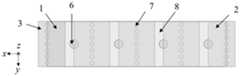
图2a为本申请实施例提供的一种毫米波宽带波束扫描天线阵列的主视图。FIG. 2a is a front view of a millimeter-wave broadband beam scanning antenna array provided by an embodiment of the present application.
图2b为本申请实施例提供的一种毫米波宽带波束扫描天线阵列的俯视图。FIG. 2b is a top view of a millimeter-wave broadband beam scanning antenna array provided by an embodiment of the present application.
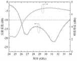
图3为本申请实施例提供的一种半模Vivaldi天线单元在工作频带范围内的反射系数和峰值增益仿真曲线图。FIG. 3 is a simulation curve diagram of reflection coefficient and peak gain of a half-mode Vivaldi antenna unit in a working frequency band range provided by an embodiment of the present application.
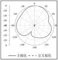
图4a为本申请实施例提供的一种半模Vivaldi天线单元在27GHz频点xoz面主极化及交叉极化仿真辐射方向图。FIG. 4a is a simulated radiation pattern of the main polarization and cross-polarization of a half-mode Vivaldi antenna unit at a frequency point of 27 GHz on the xoz plane according to an embodiment of the present application.
图4b为本申请实施例提供的一种半模Vivaldi天线单元在27GHz频点yoz面主极化及交叉极化仿真辐射方向图。FIG. 4b is a simulated radiation pattern of the main polarization and cross-polarization of a half-mode Vivaldi antenna unit at a frequency point of 27 GHz on the yoz plane according to an embodiment of the present application.
图5a为本申请实施例提供的一种毫米波宽带波束扫描天线阵列在不加载隔离金属通孔时的反射系数仿真曲线图。FIG. 5a is a simulation curve diagram of the reflection coefficient of a millimeter-wave broadband beam scanning antenna array provided by an embodiment of the present application when no isolation metal through holes are loaded.
图5b为本申请实施例提供的一种毫米波宽带波束扫描天线阵列在加载隔离金属通孔时的反射系数仿真曲线图。FIG. 5b is a simulation curve diagram of a reflection coefficient of a millimeter-wave broadband beam scanning antenna array provided by an embodiment of the present application when an isolation metal through hole is loaded.
图6a为本申请实施例提供的一种毫米波宽带波束扫描天线阵列在不加载隔离金属通孔时的隔离度仿真曲线图。FIG. 6a is an isolation simulation curve diagram of a millimeter-wave broadband beam scanning antenna array provided by an embodiment of the present application when no isolation metal through holes are loaded.
图6b为本申请实施例提供的一种毫米波宽带波束扫描天线阵列在加载隔离金属通孔时的隔离度仿真曲线图。FIG. 6b is an isolation simulation curve diagram of a millimeter-wave broadband beam scanning antenna array provided by an embodiment of the present application when an isolation metal through hole is loaded.
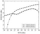
图7为本申请实施例提供的一种毫米波宽带波束扫描天线阵列在单元均同相馈电时不加载金属隔离通孔与加载金属隔离通孔的仿真峰值增益对比曲线图。FIG. 7 is a graph comparing the simulated peak gain of a millimeter-wave wideband beam scanning antenna array provided by an embodiment of the present application when all elements are fed in phase without metal isolation vias and loaded with metal isolation vias.
图8a为本申请实施例提供的一种毫米波宽带波束扫描天线阵列在单元均同相馈电时于28GHz频点xoz面主极化及交叉极化仿真辐射方向图。FIG. 8a is a simulated radiation pattern of the main polarization and cross-polarization on the xoz plane at the 28GHz frequency point of a millimeter-wave wideband beam scanning antenna array provided by an embodiment of the present application when all elements are fed in-phase.
图8b为本申请实施例提供的一种毫米波宽带波束扫描天线阵列在单元均同相馈电时于28GHz频点yoz面主极化及交叉极化仿真辐射方向图。FIG. 8b is a simulated radiation pattern of the main polarization and cross-polarization on the yoz plane at the 28 GHz frequency point of a millimeter-wave broadband beam scanning antenna array provided by an embodiment of the present application when all elements are fed in-phase.
图9为本申请实施例提供的一种毫米波宽带波束扫描天线阵列的仿真波束扫描性能曲线图。FIG. 9 is a graph of simulated beam scanning performance of a millimeter-wave broadband beam scanning antenna array provided by an embodiment of the present application.
附图标号:Reference number:
1、半个Vivaldi辐射壁;1. Half a Vivaldi radiant wall;
2、垂直金属壁;2. Vertical metal wall;
3、第一金属板;3. The first metal plate;
4、介质基板;4. Dielectric substrate;
5、第二金属板;5. The second metal plate;
6、同轴馈电单元;6. Coaxial feed unit;
7、金属隔离通孔;7. Metal isolation through holes;
8、辐射缝隙;8. Radiation gap;
9、金属隔离单元;9. Metal isolation unit;
10、3D打印介质结构。10. 3D printing medium structure.
具体实施方式Detailed ways
为使本申请的目的、技术方案和优点更加清楚明白,下面结合实施方式和附图,对本申请做进一步详细说明。在此,本申请的示意性实施方式及其说明用于解释本申请,但并不作为对本申请的限定。In order to make the objectives, technical solutions and advantages of the present application more clear, the present application will be further described in detail below with reference to the embodiments and the accompanying drawings. Here, the exemplary embodiments and descriptions of the present application are used to explain the present application, but are not intended to limit the present application.
在此,还需要说明的是,为了避免因不必要的细节而模糊了本申请,在附图中仅仅示出了与根据本申请的方案密切相关的结构和/或处理步骤,而省略了与本申请关系不大的其他细节。Here, it should also be noted that, in order to avoid obscuring the present application due to unnecessary details, only the structures and/or processing steps closely related to the solution according to the present application are shown in the drawings, and the related structures and/or processing steps are omitted. Other details not relevant to this application.
应该强调,术语“包括/包含”在本文使用时指特征、要素、步骤或组件的存在,但并不排除一个或更多个其它特征、要素、步骤或组件的存在或附加。It should be emphasized that the term "comprising/comprising" when used herein refers to the presence of a feature, element, step or component, but does not exclude the presence or addition of one or more other features, elements, steps or components.
在此,还需要说明的是,如果没有特殊说明,术语“连接”在本文不仅可以指直接连接,也可以表示存在中间物的间接连接。Here, it should also be noted that, if there is no special description, the term "connection" herein may not only refer to direct connection, but also to indicate indirect connection with intermediates.
在下文中,将参考附图描述本申请的实施例。在附图中,相同的附图标记代表相同或类似的部件,或者相同或类似的步骤。Hereinafter, embodiments of the present application will be described with reference to the accompanying drawings. In the drawings, the same reference numbers represent the same or similar parts, or the same or similar steps.
在本申请的一个或多个实施例中,所述半个Vivaldi辐射壁也可以被称之为:Vivaldi辐射臂的一半。In one or more embodiments of the present application, the half Vivaldi radiating wall may also be referred to as: half of the Vivaldi radiating arm.
在本申请的一个或多个实施例中,所述第一金属板也可以被称之为:顶层金属板。In one or more embodiments of the present application, the first metal plate may also be referred to as a top metal plate.
在本申请的一个或多个实施例中,所述第二金属板也可以被称之为:金属地板。In one or more embodiments of the present application, the second metal plate may also be referred to as a metal floor.
在本申请的一个或多个实施例中,所述同轴馈电单元也可以被称之为:同轴馈电结构。In one or more embodiments of the present application, the coaxial feeding unit may also be referred to as a coaxial feeding structure.
在本申请的一个或多个实施例中,半模Vivaldi天线单元也可以被称之为:小型化毫米波半模Vivaldi天线单元。In one or more embodiments of the present application, the half-mode Vivaldi antenna unit may also be referred to as: a miniaturized millimeter-wave half-mode Vivaldi antenna unit.
在本申请的一个或多个实施例中,毫米波宽带波束扫描天线阵列也可以被称之为:小型化毫米波宽带宽角度扫描天线阵列。In one or more embodiments of the present application, the millimeter-wave broadband beam scanning antenna array may also be referred to as: a miniaturized millimeter-wave wide-bandwidth angle scanning antenna array.
为了兼顾毫米波宽带波束扫描天线阵列的小型化和宽角扫描性能,参见图1a、图1b、图2a和图2b,本申请实施例提供一种毫米波宽带波束扫描天线阵列,具体为一种小型化毫米波宽带宽角度扫描天线阵列,所述毫米波宽带波束扫描天线阵列具体包含有如下内容:In order to take into account the miniaturization and wide-angle scanning performance of the millimeter-wave broadband beam scanning antenna array, referring to FIGS. 1a, 1b, 2a, and 2b, an embodiment of the present application provides a millimeter-wave broadband beam scanning antenna array, specifically a A miniaturized millimeter-wave wide-bandwidth angular scanning antenna array, the millimeter-wave wide-bandwidth beam scanning antenna array specifically includes the following contents:
多个采用半模毫米波宽带波束扫描天线单元的天线阵元,以及,用于隔离各个所述天线阵元之间能量的隔离组件;各个所述天线阵元依次相接且同向固定设置在一金属介质组板的一侧面板上,且所述隔离组件设置在该金属介质组板中,所述金属介质组板的另一侧面板上设有同轴馈电单元6。A plurality of antenna array elements using a half-mode millimeter wave broadband beam scanning antenna unit, and an isolation component for isolating the energy between the antenna array elements; the antenna array elements are connected in sequence and fixedly arranged in the same direction. One side panel of a metal dielectric board, and the isolation component is arranged in the metal dielectric board, and the other side panel of the metal dielectric board is provided with a
为了进一步优化半模毫米波宽带波束扫描天线单元,在本申请的的一个实施例中,可以选用半模Vivaldi天线单元。其中,所述半模Vivaldi天线单元包括:半个Vivaldi辐射壁1和一个垂直金属壁2,其中,所述半个Vivaldi辐射壁1为自Vivaldi天线的中心线处切分得到的部件;所述半个Vivaldi辐射壁1和所述垂直金属壁2的底部均固定设置在所述金属介质组板上;且该半个Vivaldi辐射壁1和所述垂直金属壁2之间形成有辐射缝隙8。In order to further optimize the half-mode millimeter-wave broadband beam scanning antenna unit, in an embodiment of the present application, a half-mode Vivaldi antenna unit may be selected. Wherein, the half-mode Vivaldi antenna unit includes: a half
具体来说,所述Vivaldi天线是通过采用指数形状的缝隙结构来控制电磁波从缝隙的一端向开口端辐射电磁能量的缝隙微带天线。一般由三层材料组成:Specifically, the Vivaldi antenna is a slot microstrip antenna that uses an exponentially shaped slot structure to control electromagnetic waves to radiate electromagnetic energy from one end of the slot to the open end. Generally consists of three layers of materials:
(1)最顶层是金属接地板,在该接地板上掏出由槽线所围的缝隙结构,槽线由三部分构成:第一部分是圆形槽线,对微带传输线起到阻抗匹配作用;第二部分是矩形槽线,和微带传输线起到相互耦合传输电磁波的作用;第三部分是渐变槽线,对天线所辐射的电磁波起到引向作用。且两个渐变槽线之间的中心线可以被认为是Vivaldi天线的中心线,而本申请中提及的所述半个Vivaldi辐射壁1是指以Vivaldi天线的中心线处对Vivaldi天线进行切分并得到的一半的部件,且该部件中含有一个所述渐变槽线。(1) The top layer is a metal grounding plate. On the grounding plate, a slot structure surrounded by a slot line is drawn. The slot line is composed of three parts: the first part is a circular slot line, which plays an impedance matching role for the microstrip transmission line. ; The second part is a rectangular slot line, and the microstrip transmission line plays the role of mutual coupling and transmission of electromagnetic waves; the third part is a gradient slot line, which guides the electromagnetic waves radiated by the antenna. And the center line between the two gradient groove lines can be regarded as the center line of the Vivaldi antenna, and the half
(2)中间层是介质板。(2) The intermediate layer is a dielectric plate.
(3)最底层是金属微带线,微带线的终端为扇形结构,主要起到终端负载匹配作用,且两个扇形结构的凸处相对处可以被认为是Vivaldi天线的中心线;微带线通过该介质板向槽线耦合馈电。(3) The bottom layer is a metal microstrip line. The terminal of the microstrip line is a fan-shaped structure, which mainly plays the role of terminal load matching, and the opposite position of the convex parts of the two fan-shaped structures can be regarded as the center line of the Vivaldi antenna; The line feeds the slot line coupling through this dielectric plate.
为了进一步提高金属介质组板的应用可靠性,在本申请的毫米波宽带波束扫描天线阵列中的一个实施例中,所述金属介质组板可以具体包含有:In order to further improve the application reliability of the metal dielectric board, in an embodiment of the millimeter wave broadband beam scanning antenna array of the present application, the metal dielectric board may specifically include:
介质基板4、设置在该介质基板4一侧面板的第一金属板3以及设置在该介质基板4另一侧面板的第二金属板5;各个所述半个Vivaldi辐射壁1和所述垂直金属壁2均固定设置在所述第一金属板3上,所述同轴馈电单元6固定设置在所述第二金属板5上,且该同轴馈电单元6的内管延伸并贯穿所述介质基板4。可以理解的是,所述同轴馈电单元6可以固定设置在所述第二金属板5的中心点上。The
为了进一步提高隔离组件的应用可靠性,在本申请的毫米波宽带波束扫描天线阵列中的一个实施例中,所述隔离组件可以具体包含有:In order to further improve the application reliability of the isolation component, in an embodiment of the millimeter wave broadband beam scanning antenna array of the present application, the isolation component may specifically include:
设置在所述介质基板4内的多列金属隔离单元9;各列所述金属隔离单元9分别与所述半模Vivaldi天线单元的边缘对应设置,其中,所述半模Vivaldi天线单元的边缘包括:所述半个Vivaldi辐射壁1底部的远离与其属于同一半模Vivaldi天线单元的所述垂直金属壁2的一侧边缘,以及,所述垂直金属壁2底部的远离与其属于同一半模Vivaldi天线单元的所述半个Vivaldi辐射壁1的一侧边缘。Multiple rows of metal isolation units 9 disposed in the
为了进一步提高金属隔离单元的应用可靠性,在本申请的毫米波宽带波束扫描天线阵列中的一个实施例中,所述金属隔离单元可以具体包含有:In order to further improve the application reliability of the metal isolation unit, in an embodiment of the millimeter wave broadband beam scanning antenna array of the present application, the metal isolation unit may specifically include:
多个金属隔离通孔7;各个所述金属隔离通孔7均在所述金属介质组板中形成,且在垂直于所述金属介质组板的板面的方向延伸。A plurality of metal isolation through
为了进一步提高半模Vivaldi天线单元的应用可靠性,在本申请的毫米波宽带波束扫描天线阵列中的一个实施例中,在相邻的两个所述半模Vivaldi天线单元中,一个所述半模Vivaldi天线单元中的所述半个Vivaldi辐射壁1和另一个所述半模Vivaldi天线单元中的所述垂直金属壁2之间固定连接。In order to further improve the application reliability of the half-mode Vivaldi antenna unit, in an embodiment of the millimeter-wave wideband beam scanning antenna array of the present application, in two adjacent half-mode Vivaldi antenna units, one of the half-mode Vivaldi antenna units The half
其中,相接的一个所述半模Vivaldi天线单元中的所述半个Vivaldi辐射壁1和另一个所述半模Vivaldi天线单元中的所述垂直金属壁2为一体成型的3D打印介质结构10。所述3D打印介质结构10的外表面覆盖有铜层。Wherein, the half
为了进一步提升毫米波室外通信中定点与移动终端的通信性能,在本申请的毫米波宽带波束扫描天线阵列中的一个实施例中,所述半模Vivaldi天线单元的数量为4,且所述金属隔离单元9的列数为5。也就是说,在该实施例中,毫米波宽带波束扫描天线阵列,包括四个半模Vivaldi天线单元结构,每个半模Vivaldi天线单元包括半个Vivaldi辐射壁以及垂直金属壁结构,天线单元置于介质基板之上,由同轴进行馈电,所述毫米波宽带波束扫描天线阵列具体结构包括:半个Vivaldi辐射壁1,垂直金属壁2,第一金属板3、介质基板4、第二金属板5、同轴馈电单元6、金属隔离通孔7和辐射缝隙8。其中,每个阵元均由半个Vivaldi辐射壁1以及垂直金属壁2构成。在介质基板4中有五列金属隔离通孔7,用于阵元间能量去耦。第一金属板3存在四个辐射缝隙8,用于将能量耦合至半模Vivaldi天线。In order to further improve the communication performance between the fixed point and the mobile terminal in the millimeter wave outdoor communication, in an embodiment of the millimeter wave broadband beam scanning antenna array of the present application, the number of the half-mode Vivaldi antenna units is 4, and the metal The number of columns of the isolation unit 9 is five. That is to say, in this embodiment, the millimeter-wave broadband beam scanning antenna array includes four half-mode Vivaldi antenna unit structures, each half-mode Vivaldi antenna unit includes a half Vivaldi radiating wall and a vertical metal wall structure, and the antenna unit is arranged On the dielectric substrate, the feed is coaxial. The specific structure of the millimeter-wave broadband beam scanning antenna array includes: a half
其中,半个Vivaldi辐射壁1和垂直金属壁2结构均为3D打印介质结构10并整体外表面进行覆铜处理,形成铜层,非边缘区域的半个Vivaldi辐射壁1和垂直金属壁2结构可一体化加工。Among them, the half
本申请实施例提供的毫米波宽带波束扫描天线阵列,Vivaldi天线作为行波天线的一种本身具有宽带特性,基于此结构对天线进行进一步设计,为实现小型化,基于镜像理论设计了半模结构,使阵元整体尺寸降低、阵列结构紧凑;由于小型化设计减小了阵元间距,意味着阵元间的互耦作用增强,不利于天线阵列宽角扫描的性能,因此在阵元间加载单列金属通孔使阵元间能量有效隔离,从而实现去耦合,提升了天线的宽角扫描性能。In the millimeter-wave broadband beam scanning antenna array provided by the embodiment of this application, the Vivaldi antenna, as a kind of traveling wave antenna, has broadband characteristics. Based on this structure, the antenna is further designed. In order to achieve miniaturization, a half-mode structure is designed based on the mirror image theory. , the overall size of the array elements is reduced and the array structure is compact; the miniaturized design reduces the spacing of the array elements, which means that the mutual coupling between the array elements is enhanced, which is not conducive to the performance of the wide-angle scanning of the antenna array. The single-row metal through hole effectively isolates the energy between the array elements, thereby realizing decoupling and improving the wide-angle scanning performance of the antenna.
在本申请的一种具体举例中,半个Vivaldi辐射壁1的宽度为2mm,高度为5.4mm,厚度为5mm。In a specific example of the present application, the width of the half
在本申请的一种具体举例中,垂直金属壁2的宽度为2mm,高度为5.4mm,厚度为5mm。In a specific example of the present application, the
在本申请的一种具体举例中,第一金属板3和第二金属板5的尺寸均为22mm×5.1mm×0.787mm。介质基板4为罗杰斯板材,型号为5880,尺寸为22mm×5.1mm×0.787mm。In a specific example of the present application, the dimensions of the
在本申请的一种具体举例中,金属隔离通孔7的直径为0.5mm,通孔间距为0.71mm。In a specific example of the present application, the diameter of the metal isolation through
在本申请的一种具体举例中,辐射缝隙8的宽度为1mm。In a specific example of the present application, the width of the
本申请实施例提供的毫米波宽带波束扫描天线阵列的工作过程为:The working process of the millimeter-wave broadband beam scanning antenna array provided by the embodiment of the present application is as follows:
由同轴对天线阵列中的四个阵元进行馈电,能量馈入介质基板后从缝隙辐射而出,并沿半模Vivaldi结构辐射至自由空间,通过改变馈入阵元的相位差,可实现对波束指向的控制,从而实现宽角波束扫描的性能。The four array elements in the antenna array are fed coaxially, and the energy is fed into the dielectric substrate and radiated out from the slot, and radiated to the free space along the half-mode Vivaldi structure. Realize the control of beam pointing, so as to realize the performance of wide-angle beam scanning.
可选的,本申请实施例提供的毫米波宽带波束扫描天线阵列的阻抗匹配带宽为26-34吉赫(Giga Hertz,GHz),带宽覆盖第五代移动通信技术(5th generation mobilenetworks,5G)通信频段,可作为毫米波室外通信天线使用。Optionally, the impedance matching bandwidth of the millimeter wave broadband beam scanning antenna array provided by the embodiment of the present application is 26-34 gigahertz (Giga Hertz, GHz), and the bandwidth covers the fifth generation mobile communication technology (5th generation mobile networks, 5G) communication. It can be used as a millimeter-wave outdoor communication antenna.
参见图3,为本申请实施例提供的一种半模Vivaldi天线单元在工作频带范围内的反射系数和峰值增益仿真曲线图。其中,横轴表示输入信号的频率,纵轴中左轴表示反射系数,右轴表示峰值增益,反射系数表征了天线是否实现阻抗匹配,一般要求反射系数低于-10dB即达到设计要求。由图3可知,天线单元工作在25.9-33.9GHz,其峰值增益可达7.04dBi。Referring to FIG. 3 , a simulation curve diagram of a reflection coefficient and a peak gain of a half-mode Vivaldi antenna unit in a working frequency band range provided by an embodiment of the present application. Among them, the horizontal axis represents the frequency of the input signal, the left axis of the vertical axis represents the reflection coefficient, and the right axis represents the peak gain. The reflection coefficient represents whether the antenna achieves impedance matching. Generally, the reflection coefficient is required to be lower than -10dB to meet the design requirements. It can be seen from Figure 3 that the antenna unit works at 25.9-33.9GHz, and its peak gain can reach 7.04dBi.
参见图4a和图4b,为本申请实施例提供的一种半模Vivaldi天线单元在27GHz频点xoz面和yoz面主极化及交叉极化仿真辐射方向图,由于半模Vivaldi结构的不对称性,其在xoz面的辐射方向图具有一定的偏射性,在27GHz频点xoz面其偏射角度为6度,对于后续构成阵列实现波束扫描功能时,可保证在扫描角度范围内的增益稳定性。Referring to FIGS. 4a and 4b, a half-mode Vivaldi antenna unit provided for the embodiment of the application is at the 27GHz frequency point xoz plane and yoz plane main polarization and cross-polarization simulation radiation pattern, due to the asymmetry of the half-mode Vivaldi structure The radiation pattern on the xoz plane has a certain degree of polarization. At the 27GHz frequency point, the xoz plane has a polarization angle of 6 degrees. When the beam scanning function is realized in the subsequent array formation, the gain within the scanning angle range can be guaranteed. stability.
参见图5a与图5b,分别为毫米波宽带波束扫描天线阵列不加载与加载金属隔离通孔时不同阵元在工作频带范围内的反射系数仿真图。其中,横轴表示输入信号的频率,纵轴表示反射系数,带方形的曲线为S11,带三角形的曲线为S22,带圆形的曲线为S33,带倒三角形的曲线为S44。S11表示第一天线单元的反射系数,S22表示第二天线单元的反射系数,S33表示第三天线单元的反射系数,S44表示第四天线单元的反射系数,反射系数表征了天线是否实现阻抗匹配,一般要求反射系数低于-10dB即达到设计要求。对比可知,在不加载金属隔离通孔时,四个阵元的阻抗匹配性能不具有一致性,且前三个阵元工作频带极窄,第四个阵元不具有阻抗匹配特性,由图5b可知在加载金属隔离通孔后天线在26-34GHz范围内四种反射系数均低于-10dB,阻抗匹配带宽为26.67%,说明天线具有良好的宽带性能。Referring to FIG. 5a and FIG. 5b , the simulation diagrams of reflection coefficients of different array elements in the working frequency band are respectively shown when the millimeter wave broadband beam scanning antenna array is not loaded with and loaded with metal isolation through holes. The horizontal axis represents the frequency of the input signal, the vertical axis represents the reflection coefficient, the curve with a square is S11, the curve with a triangle is S22, the curve with a circle is S33, and the curve with an inverted triangle is S44. S11 represents the reflection coefficient of the first antenna element, S22 represents the reflection coefficient of the second antenna element, S33 represents the reflection coefficient of the third antenna element, S44 represents the reflection coefficient of the fourth antenna element, and the reflection coefficient indicates whether the antenna achieves impedance matching, It is generally required that the reflection coefficient is lower than -10dB to meet the design requirements. It can be seen from the comparison that the impedance matching performance of the four array elements is not consistent when the metal isolation through hole is not loaded, and the operating frequency band of the first three array elements is extremely narrow, and the fourth array element does not have impedance matching characteristics, as shown in Figure 5b It can be seen that the four reflection coefficients of the antenna in the range of 26-34GHz are all lower than -10dB after the metal isolation through hole is loaded, and the impedance matching bandwidth is 26.67%, indicating that the antenna has good broadband performance.
参见图6a和图6b,分别为毫米波宽带波束扫描天线阵列不加载和加载金属隔离通孔时在工作频带范围内的阵元间的隔离度仿真图。其中,横轴表示输入信号的频率,纵轴表示隔离度,带方形的曲线为S12,带三角形的曲线为S13,带倒三角的曲线为S14,带圆形的曲线为S23,带菱形的曲线为S24,带五边形的曲线为S34。S12表示第一天线单元与第二天线单元之间的隔离度,S13表示第一天线单元与第三天线单元之间的隔离度,S14表示第一天线单元与第四天线单元之间的隔离度,S23表示第二天线单元与第三天线单元之间的隔离度,S24表示第二天线单元与第三天线单元之间的隔离度,S34表示第三天线单元与第四天线单元之间的隔离度,一般要求其低于-15dB即达到设计要求。Referring to FIG. 6a and FIG. 6b, the simulation diagrams of the isolation between the array elements in the working frequency band range when the millimeter-wave broadband beam scanning antenna array is not loaded and loaded with metal isolation vias, respectively. Among them, the horizontal axis represents the frequency of the input signal, the vertical axis represents the isolation, the curve with square is S12, the curve with triangle is S13, the curve with inverted triangle is S14, the curve with circle is S23, the curve with diamond is S14 is S24, and the curve with the pentagon is S34. S12 represents the isolation degree between the first antenna element and the second antenna element, S13 represents the isolation degree between the first antenna element and the third antenna element, and S14 represents the isolation degree between the first antenna element and the fourth antenna element , S23 represents the isolation degree between the second antenna element and the third antenna element, S24 represents the isolation degree between the second antenna element and the third antenna element, and S34 represents the isolation degree between the third antenna element and the fourth antenna element It is generally required that it is lower than -15dB to meet the design requirements.
对比可知,在不加载金属隔离通孔时,不同端口间的隔离度呈现出较大的差异性,相邻端口隔离度约为8dB,因此互耦作用极强,影响天线的波束扫描性能,在加载金属隔离通孔后,天线在26-34GHz的阻抗匹配带宽内,各天线单元隔离度均低于-15dB,满足天线隔离度的设计要求,说明天线单元之间互耦作用很小,有利于天线实现宽角扫描的性能。The comparison shows that when no metal isolation vias are loaded, the isolation between different ports shows a large difference, and the isolation of adjacent ports is about 8dB, so the mutual coupling effect is very strong, which affects the beam scanning performance of the antenna. After the metal isolation through hole is loaded, the antenna is within the impedance matching bandwidth of 26-34GHz, and the isolation of each antenna unit is lower than -15dB, which meets the design requirements of the antenna isolation, indicating that the mutual coupling between the antenna units is small, which is beneficial to The antenna achieves wide-angle scanning performance.
参见图7,图7为毫米波宽带波束扫描天线阵列在工作频带范围内的峰值增益仿真图,其中,横轴表示输入信号的频率,纵轴表示峰值增益。由图7可知,天线在26-34GHz范围内,最大增益可达12.2dBi,说明天线具有高增益的特性。Referring to FIG. 7, FIG. 7 is a simulation diagram of the peak gain of the millimeter-wave broadband beam scanning antenna array in the working frequency band, wherein the horizontal axis represents the frequency of the input signal, and the vertical axis represents the peak gain. It can be seen from Figure 7 that the maximum gain of the antenna can reach 12.2dBi in the range of 26-34GHz, indicating that the antenna has the characteristics of high gain.
图8a和图8b为毫米波宽带波束扫描天线阵列在28GHz阵元均同相馈电时的XOZ面和YOZ面的辐射方向图仿真结果,辐射方向图具有良好的对称性。Figures 8a and 8b show the simulation results of the radiation patterns of the XOZ plane and the YOZ plane of the millimeter-wave broadband beam scanning antenna array when the 28GHz elements are fed in-phase, and the radiation patterns have good symmetry.
图9为毫米波宽带波束扫描天线阵列的仿真波束扫描性能曲线图,天线阵列的扫描角度可覆盖-51度至47度,实现了宽角扫描性能,在扫描范围内,其增益波动低于0.96dB,具有很高的稳定性。Figure 9 is a graph of the simulated beam scanning performance of the millimeter-wave broadband beam scanning antenna array. The scanning angle of the antenna array can cover -51 degrees to 47 degrees, achieving wide-angle scanning performance. Within the scanning range, its gain fluctuation is lower than 0.96 dB, with high stability.
以上所述仅为本申请的优选实施例,并不用于限制本申请,对于本领域的技术人员来说,本申请实施例可以有各种更改和变化。凡在本申请的精神和原则之内,所作的任何修改、等同替换、改进等,均应包含在本申请的保护范围之内。The above descriptions are only preferred embodiments of the present application, and are not intended to limit the present application. For those skilled in the art, various modifications and changes may be made to the embodiments of the present application. Any modification, equivalent replacement, improvement, etc. made within the spirit and principle of this application shall be included within the protection scope of this application.
Claims (10)
Translated fromChinesePriority Applications (1)
| Application Number | Priority Date | Filing Date | Title |
|---|---|---|---|
| CN202210536739.9ACN114843777A (en) | 2022-05-17 | 2022-05-17 | Millimeter Wave Broadband Beam Scanning Antenna Array |
Applications Claiming Priority (1)
| Application Number | Priority Date | Filing Date | Title |
|---|---|---|---|
| CN202210536739.9ACN114843777A (en) | 2022-05-17 | 2022-05-17 | Millimeter Wave Broadband Beam Scanning Antenna Array |
Publications (1)
| Publication Number | Publication Date |
|---|---|
| CN114843777Atrue CN114843777A (en) | 2022-08-02 |
Family
ID=82570825
Family Applications (1)
| Application Number | Title | Priority Date | Filing Date |
|---|---|---|---|
| CN202210536739.9APendingCN114843777A (en) | 2022-05-17 | 2022-05-17 | Millimeter Wave Broadband Beam Scanning Antenna Array |
Country Status (1)
| Country | Link |
|---|---|
| CN (1) | CN114843777A (en) |
Cited By (2)
| Publication number | Priority date | Publication date | Assignee | Title |
|---|---|---|---|---|
| CN116826365A (en)* | 2022-11-18 | 2023-09-29 | 江苏欧佳智能科技有限公司 | Millimeter wave wide angle scanning antenna array |
| CN117766981A (en)* | 2023-12-11 | 2024-03-26 | 中国人民解放军空军工程大学 | Beam tilting antenna |
Citations (7)
| Publication number | Priority date | Publication date | Assignee | Title |
|---|---|---|---|---|
| CN109428152A (en)* | 2017-08-21 | 2019-03-05 | 比亚迪股份有限公司 | Antenna element, trailer-mounted radar and automobile |
| WO2019054094A1 (en)* | 2017-09-12 | 2019-03-21 | 株式会社村田製作所 | Antenna module |
| CN110739536A (en)* | 2019-09-27 | 2020-01-31 | 上海大学 | Half-mode Vivaldi antenna and miniaturized large-angle frequency-sweep antenna array |
| WO2020187146A1 (en)* | 2019-03-20 | 2020-09-24 | Oppo广东移动通信有限公司 | Millimeter wave module and electronic device |
| US20200321708A1 (en)* | 2019-04-08 | 2020-10-08 | Phase Sensitive Innovations, Inc. | Ultra-wideband Modular Tightly Coupled Array Antenna |
| CN111987448A (en)* | 2020-09-18 | 2020-11-24 | 上海无线电设备研究所 | Dual-polarized Vivaldi antenna |
| CN112117551A (en)* | 2020-08-19 | 2020-12-22 | 扬州船用电子仪器研究所(中国船舶重工集团公司第七二三研究所) | Ultra-wideband wide-angle scanning all-metal Vivaldi array antenna |
- 2022
- 2022-05-17CNCN202210536739.9Apatent/CN114843777A/enactivePending
Patent Citations (7)
| Publication number | Priority date | Publication date | Assignee | Title |
|---|---|---|---|---|
| CN109428152A (en)* | 2017-08-21 | 2019-03-05 | 比亚迪股份有限公司 | Antenna element, trailer-mounted radar and automobile |
| WO2019054094A1 (en)* | 2017-09-12 | 2019-03-21 | 株式会社村田製作所 | Antenna module |
| WO2020187146A1 (en)* | 2019-03-20 | 2020-09-24 | Oppo广东移动通信有限公司 | Millimeter wave module and electronic device |
| US20200321708A1 (en)* | 2019-04-08 | 2020-10-08 | Phase Sensitive Innovations, Inc. | Ultra-wideband Modular Tightly Coupled Array Antenna |
| CN110739536A (en)* | 2019-09-27 | 2020-01-31 | 上海大学 | Half-mode Vivaldi antenna and miniaturized large-angle frequency-sweep antenna array |
| CN112117551A (en)* | 2020-08-19 | 2020-12-22 | 扬州船用电子仪器研究所(中国船舶重工集团公司第七二三研究所) | Ultra-wideband wide-angle scanning all-metal Vivaldi array antenna |
| CN111987448A (en)* | 2020-09-18 | 2020-11-24 | 上海无线电设备研究所 | Dual-polarized Vivaldi antenna |
Non-Patent Citations (2)
| Title |
|---|
| YIN ZHANGFEI 等: "Miniaturized Ultrawideband Half-Mode Vivaldi Antenna Based on Mirror Image Theory", 《 IEEE ANTENNAS AND WIRELESS PROPAGATION LETTERS》, 30 April 2020 (2020-04-30)* |
| 殷章飞: "小型化宽带 Vivaldi天线及其波束扫描阵列研究", 《中国优秀硕士学位论文全文数据库 信息科技辑》, 15 March 2021 (2021-03-15), pages 136 - 13* |
Cited By (2)
| Publication number | Priority date | Publication date | Assignee | Title |
|---|---|---|---|---|
| CN116826365A (en)* | 2022-11-18 | 2023-09-29 | 江苏欧佳智能科技有限公司 | Millimeter wave wide angle scanning antenna array |
| CN117766981A (en)* | 2023-12-11 | 2024-03-26 | 中国人民解放军空军工程大学 | Beam tilting antenna |
Similar Documents
| Publication | Publication Date | Title |
|---|---|---|
| CN110137672B (en) | A beam scanning antenna array integrating side-fire and end-fire | |
| CN103367917B (en) | Mobile device | |
| CN107732445B (en) | A millimeter-wave circularly polarized array antenna and its radiator | |
| WO2022021824A1 (en) | Low-frequency radiation unit and base station antenna | |
| CN111883910B (en) | A dual-polarized low-profile magnetoelectric dipole antenna and wireless communication device | |
| WO2019213878A1 (en) | Millimeter wave antenna array unit, array antenna, and communication product | |
| CN113285220B (en) | Dual-frequency common-aperture phased array antenna, communication device and system | |
| CN112332085B (en) | Ka wave band double circular polarization switchable receiving and transmitting antenna | |
| CN114069257B (en) | An ultra-wideband dual-polarized phased array antenna based on strongly coupled dipoles | |
| CN110034406A (en) | A kind of low section multi-beam slot antenna based on the double-deck super surface | |
| CN107369895A (en) | One kind orientation high-gain microstrip antenna | |
| CN113690636B (en) | Millimeter wave wide-angle scanning phased-array antenna based on super surface | |
| CN114843777A (en) | Millimeter Wave Broadband Beam Scanning Antenna Array | |
| CN106229649A (en) | A kind of compact conformal array array antenna of genome units based on LTCC technology | |
| CN108134203A (en) | Big unit spacing large-angle scanning phased array antenna based on electromagnetic bandgap structure | |
| CN118645801A (en) | Novel broadband high isolation two-dimensional wide-angle scanning phased array antenna unit and array | |
| CN115173068B (en) | Broadband circularly polarized substrate integrated waveguide horn antenna array and wireless communication equipment | |
| CN110504527B (en) | L and X wave band common-caliber antenna with novel structure | |
| CN114336001A (en) | Antenna units, arrays, devices and terminals | |
| CN115377674A (en) | A 5G millimeter-wave broadband dual-polarization antenna unit and antenna array | |
| CN220753757U (en) | K-band high-gain broadband microstrip antenna and antenna unit | |
| CN113964489B (en) | Wide-angle scanning phased array antenna based on bent-shaped slot | |
| US20250102655A1 (en) | Antenna unit | |
| CN116505252A (en) | A Ku-band Wide Bandwidth Beam Circularly Polarized Microstrip Antenna | |
| CN115799819A (en) | Millimeter wave wide beam circular polarization double-layer microstrip patch antenna |
Legal Events
| Date | Code | Title | Description |
|---|---|---|---|
| PB01 | Publication | ||
| PB01 | Publication | ||
| SE01 | Entry into force of request for substantive examination | ||
| SE01 | Entry into force of request for substantive examination |