CN114843543A - A superhydrophobic condensed water surface and preparation method thereof, battery electrode plate and fuel cell - Google Patents
A superhydrophobic condensed water surface and preparation method thereof, battery electrode plate and fuel cellDownload PDFInfo
- Publication number
- CN114843543A CN114843543ACN202210629199.9ACN202210629199ACN114843543ACN 114843543 ACN114843543 ACN 114843543ACN 202210629199 ACN202210629199 ACN 202210629199ACN 114843543 ACN114843543 ACN 114843543A
- Authority
- CN
- China
- Prior art keywords
- graphite
- fuel cell
- film layer
- condensed water
- laser beam
- Prior art date
- Legal status (The legal status is an assumption and is not a legal conclusion. Google has not performed a legal analysis and makes no representation as to the accuracy of the status listed.)
- Pending
Links
- XLYOFNOQVPJJNP-UHFFFAOYSA-NwaterSubstancesOXLYOFNOQVPJJNP-UHFFFAOYSA-N0.000titleclaimsabstractdescription71
- 239000000446fuelSubstances0.000titleclaimsabstractdescription62
- 230000003075superhydrophobic effectEffects0.000titleclaimsabstractdescription21
- 238000002360preparation methodMethods0.000titleabstractdescription12
- OKTJSMMVPCPJKN-UHFFFAOYSA-NCarbonChemical compound[C]OKTJSMMVPCPJKN-UHFFFAOYSA-N0.000claimsabstractdescription116
- 229910002804graphiteInorganic materials0.000claimsabstractdescription114
- 239000010439graphiteSubstances0.000claimsabstractdescription114
- 238000000034methodMethods0.000claimsabstractdescription43
- 239000010409thin filmSubstances0.000claimsabstractdescription39
- XKRFYHLGVUSROY-UHFFFAOYSA-NArgonChemical compound[Ar]XKRFYHLGVUSROY-UHFFFAOYSA-N0.000claimsabstractdescription38
- 230000002209hydrophobic effectEffects0.000claimsabstractdescription29
- BLRPTPMANUNPDV-UHFFFAOYSA-NSilaneChemical compound[SiH4]BLRPTPMANUNPDV-UHFFFAOYSA-N0.000claimsabstractdescription24
- 239000011248coating agentSubstances0.000claimsabstractdescription24
- 238000000576coating methodMethods0.000claimsabstractdescription24
- 229910000077silaneInorganic materials0.000claimsabstractdescription24
- 239000002245particleSubstances0.000claimsabstractdescription22
- 239000007789gasSubstances0.000claimsabstractdescription20
- 229910052786argonInorganic materials0.000claimsabstractdescription19
- 238000007740vapor depositionMethods0.000claimsabstractdescription17
- 239000010408filmSubstances0.000claimsdescription11
- XPBBUZJBQWWFFJ-UHFFFAOYSA-NfluorosilaneChemical compound[SiH3]FXPBBUZJBQWWFFJ-UHFFFAOYSA-N0.000claimsdescription6
- 239000002105nanoparticleSubstances0.000claimsdescription6
- 238000000151depositionMethods0.000claimsdescription5
- 230000008021depositionEffects0.000claimsdescription5
- 239000002086nanomaterialSubstances0.000claimsdescription5
- 238000010586diagramMethods0.000description18
- 239000013077target materialSubstances0.000description8
- 238000009792diffusion processMethods0.000description5
- 238000009833condensationMethods0.000description4
- 230000005494condensationEffects0.000description4
- 239000000758substrateSubstances0.000description4
- 238000002309gasificationMethods0.000description3
- 239000007788liquidSubstances0.000description3
- 239000012528membraneSubstances0.000description3
- 238000009825accumulationMethods0.000description2
- 230000003197catalytic effectEffects0.000description2
- 230000000694effectsEffects0.000description2
- 238000010304firingMethods0.000description2
- 238000012986modificationMethods0.000description2
- 230000004048modificationEffects0.000description2
- 239000012495reaction gasSubstances0.000description2
- 230000005540biological transmissionEffects0.000description1
- 230000015572biosynthetic processEffects0.000description1
- 230000015556catabolic processEffects0.000description1
- 238000006243chemical reactionMethods0.000description1
- 239000000306componentSubstances0.000description1
- 238000001816coolingMethods0.000description1
- 230000010485copingEffects0.000description1
- 239000008358core componentSubstances0.000description1
- 238000006731degradation reactionMethods0.000description1
- 230000005611electricityEffects0.000description1
- 238000003487electrochemical reactionMethods0.000description1
- 230000002349favourable effectEffects0.000description1
- 239000011881graphite nanoparticleSubstances0.000description1
- 230000005661hydrophobic surfaceEffects0.000description1
- 239000011261inert gasSubstances0.000description1
- 239000000463materialSubstances0.000description1
- 239000011148porous materialSubstances0.000description1
- 238000005096rolling processMethods0.000description1
- 238000009736wettingMethods0.000description1
Images


Classifications
- H—ELECTRICITY
- H01—ELECTRIC ELEMENTS
- H01M—PROCESSES OR MEANS, e.g. BATTERIES, FOR THE DIRECT CONVERSION OF CHEMICAL ENERGY INTO ELECTRICAL ENERGY
- H01M8/00—Fuel cells; Manufacture thereof
- H01M8/02—Details
- H01M8/0202—Collectors; Separators, e.g. bipolar separators; Interconnectors
- H01M8/023—Porous and characterised by the material
- H01M8/0241—Composites
- H01M8/0245—Composites in the form of layered or coated products
- H—ELECTRICITY
- H01—ELECTRIC ELEMENTS
- H01M—PROCESSES OR MEANS, e.g. BATTERIES, FOR THE DIRECT CONVERSION OF CHEMICAL ENERGY INTO ELECTRICAL ENERGY
- H01M8/00—Fuel cells; Manufacture thereof
- H01M8/02—Details
- H01M8/0202—Collectors; Separators, e.g. bipolar separators; Interconnectors
- H01M8/023—Porous and characterised by the material
- H01M8/0234—Carbonaceous material
- Y—GENERAL TAGGING OF NEW TECHNOLOGICAL DEVELOPMENTS; GENERAL TAGGING OF CROSS-SECTIONAL TECHNOLOGIES SPANNING OVER SEVERAL SECTIONS OF THE IPC; TECHNICAL SUBJECTS COVERED BY FORMER USPC CROSS-REFERENCE ART COLLECTIONS [XRACs] AND DIGESTS
- Y02—TECHNOLOGIES OR APPLICATIONS FOR MITIGATION OR ADAPTATION AGAINST CLIMATE CHANGE
- Y02E—REDUCTION OF GREENHOUSE GAS [GHG] EMISSIONS, RELATED TO ENERGY GENERATION, TRANSMISSION OR DISTRIBUTION
- Y02E60/00—Enabling technologies; Technologies with a potential or indirect contribution to GHG emissions mitigation
- Y02E60/30—Hydrogen technology
- Y02E60/50—Fuel cells
Landscapes
- Chemical & Material Sciences (AREA)
- Life Sciences & Earth Sciences (AREA)
- Engineering & Computer Science (AREA)
- Manufacturing & Machinery (AREA)
- Sustainable Development (AREA)
- Sustainable Energy (AREA)
- Chemical Kinetics & Catalysis (AREA)
- Electrochemistry (AREA)
- General Chemical & Material Sciences (AREA)
- Fuel Cell (AREA)
- Composite Materials (AREA)
Abstract
Translated fromChinese
Description
Translated fromChinese技术领域technical field
本发明涉及燃料电池领域,具体而言,涉及一种超疏冷凝水表面及其制备方法、电池极板和燃料电池。The invention relates to the field of fuel cells, in particular to a superphobic condensed water surface and a preparation method thereof, a battery electrode plate and a fuel cell.
背景技术Background technique
质子交换膜燃料电池(PEMFC)具有清洁无污染、噪音低、效率高、启动快速以及低温环境适应性良好等特点,可广泛应用于交通、能源等领域。双极板是燃料电池的核心部件之一,具有共用通道、阴极流场、阳极流场和冷却流场等结构,主要功能包括均匀分配燃料电池内部反应气体、移除反应水、导电导热以及提供机械支撑等。Proton exchange membrane fuel cell (PEMFC) has the characteristics of clean and pollution-free, low noise, high efficiency, fast start-up and good adaptability to low temperature environment, and can be widely used in transportation, energy and other fields. The bipolar plate is one of the core components of the fuel cell. It has structures such as a common channel, cathode flow field, anode flow field and cooling flow field. Its main functions include evenly distributing the reaction gas inside the fuel cell, removing reaction water, conducting electricity and heat conduction, and providing Mechanical support, etc.
图1a为燃料电池流场水淹示意图,在高电流密度的运行条件下,燃料电池阴极侧会因电化学反应及电渗拖拽效应产生大量的水,从而造成双极板阴极流场内液态水的积聚,严重时会导致水淹,进而阻碍反应气体的有效传输和扩散,导致燃料电池性能的衰减和内部组件的损伤。因此,在燃料电池应用中通常会对双极板流场进行疏水处理。Figure 1a is a schematic diagram of water flooding in the flow field of the fuel cell. Under the operating conditions of high current density, a large amount of water will be generated on the cathode side of the fuel cell due to the electrochemical reaction and electroosmotic drag effect, resulting in a liquid state in the cathode flow field of the bipolar plate. The accumulation of water, in severe cases, can lead to flooding, which in turn hinders the efficient transport and diffusion of reactive gases, resulting in degradation of fuel cell performance and damage to internal components. Therefore, bipolar plate flow fields are often hydrophobicized in fuel cell applications.
在实现本说明书实施例的过程中,发明人发现:In the process of implementing the embodiments of the present specification, the inventors found that:
由于质子交换膜燃料电池常常在高温下运行,在催化层容易产生大量的气态水,而催化层和双极板之间存在较大的温差,水气在双极板流场降温容易形成冷凝水。另外,为了充分润湿质子交换膜,通常会对反应气体进行加湿,进一步加剧了流场中的冷凝效应。图1b示出了现有技术中超疏水表面在冷凝环境下失效示意图,燃料电池在运行时,冷凝水会浸润双极板的疏水或超疏水表面的微缺陷和微纳结构,导致疏水表面的失效,引发液态水在流场内部的积聚,从而造成水淹现象,阻碍水和反应气体的传输和扩散,降低燃料电池的功率密度和寿命。Since proton exchange membrane fuel cells often operate at high temperatures, a large amount of gaseous water is easily generated in the catalytic layer, and there is a large temperature difference between the catalytic layer and the bipolar plate, and the water vapor is easily cooled in the bipolar plate flow field to form condensed water . In addition, in order to fully wet the proton exchange membrane, the reaction gas is usually humidified, which further exacerbates the condensation effect in the flow field. Figure 1b shows a schematic diagram of the failure of the superhydrophobic surface in the prior art in a condensation environment. When the fuel cell is running, the condensed water will infiltrate the micro-defects and micro-nano structures of the hydrophobic or superhydrophobic surface of the bipolar plate, resulting in the failure of the hydrophobic surface. , causing the accumulation of liquid water inside the flow field, resulting in flooding, hindering the transmission and diffusion of water and reactive gases, and reducing the power density and life of the fuel cell.
发明内容SUMMARY OF THE INVENTION
本发明提供一种超疏冷凝水表面及其制备方法、电池极板和燃料电池,用以克服现有技术中存在的至少一个问题。The present invention provides a super-hydrophobic condensed water surface and a preparation method thereof, a battery electrode plate and a fuel cell, so as to overcome at least one problem existing in the prior art.
根据本说明书实施例的第一方面,提供了一种超疏冷凝水表面的制备方法,包括:According to a first aspect of the embodiments of the present specification, a method for preparing a superphobic condensed water surface is provided, comprising:
在真空腔体中设置有燃料电池极板以及石墨靶材,其中,所述燃料电池极板设置在所述石墨靶材的上方;A fuel cell electrode plate and a graphite target are arranged in the vacuum cavity, wherein the fuel cell electrode plate is arranged above the graphite target;
将所述真空腔体的气压值降低至10-3Pa至3×10⁻⁴Pa后,充入氩气;After reducing the gas pressure value of the vacuum chamber to 10-3 Pa to 3×10⁻⁴ Pa, fill with argon;
向所述石墨靶材发射脉冲激光束轰击所述石墨靶材,以产生石墨等离子体,其中,所述脉冲激光束的每个脉冲具有800fs至12ps的脉宽,且所述脉冲激光束的直径为120um;Sending a pulsed laser beam to the graphite target to bombard the graphite target to generate graphite plasma, wherein each pulse of the pulsed laser beam has a pulse width of 800fs to 12ps, and the diameter of the pulsed laser beam is 120um;
所述石墨等离子体与充入的氩气碰撞并在所述燃料电池极板上沉积,形成由纳米级石墨颗粒组成的多孔石墨薄膜层;The graphite plasma collides with the charged argon gas and is deposited on the fuel cell electrode plate to form a porous graphite thin film layer composed of nanoscale graphite particles;
利用气相沉积方法在所述多孔石墨薄膜层上形成硅烷疏水涂层,以得到超疏冷凝水表面。A silane hydrophobic coating is formed on the porous graphite thin film layer by a vapor deposition method to obtain a super-hydrophobic condensed water surface.
可选的,所述利用气相沉积方法在所述多孔石墨薄膜层上形成硅烷疏水涂层,具体包括:Optionally, forming a silane hydrophobic coating on the porous graphite thin film layer by a vapor deposition method specifically includes:
将沉积有所述多孔石墨薄膜层的燃料电池极板放至另一容器中,并在所述容器中滴入氟硅烷,然后对所述容器进行抽真空,最后在温度为预设温度的烘箱里放置预设时间,使所述氟硅烷通过气相沉积方法沉积在所述多孔石墨薄膜层上,以形成硅烷疏水涂层。Put the fuel cell electrode plate on which the porous graphite thin film layer is deposited into another container, drop fluorosilane into the container, and then vacuum the container, and finally put it in an oven with a preset temperature. The fluorosilane is deposited on the porous graphite thin film layer by a vapor deposition method for a preset time, so as to form a silane hydrophobic coating.
可选的,所述石墨颗粒为纳米颗粒,所述纳米颗粒的纳米结构尺度为100nm。Optionally, the graphite particles are nanoparticles, and the nanostructure size of the nanoparticles is 100 nm.
可选的,所述多孔石墨薄膜层的厚度为1um至5um。Optionally, the thickness of the porous graphite thin film layer is 1 um to 5 um.
可选的,向所述真空腔体内充入的氩气的气压为10Pa至50Pa。Optionally, the gas pressure of the argon gas filled into the vacuum chamber is 10Pa to 50Pa.
可选的,所述向所述石墨靶材发射脉冲激光束轰击所述石墨靶材,在所述燃料电池极板上沉积石墨等离子体,还包括:所述激光束的平均输出功率为50W至200W,脉冲频率为100kHz至1000kHz,靶基距为25mm至50mm,沉积时间为5分钟。Optionally, the firing of a pulsed laser beam to the graphite target to bombard the graphite target, and the deposition of graphite plasma on the fuel cell electrode plate, further includes: the average output power of the laser beam is 50W to 50W 200W, the pulse frequency is 100kHz to 1000kHz, the target base distance is 25mm to 50mm, and the deposition time is 5 minutes.
根据本说明书实施例的第二方面,提供了一种超疏冷凝水表面,所述超疏冷凝水表面采用如第一方面中任一技术方案所述的超疏冷凝水表面的制备方法制备而成,包括:沉积在燃料电池双极板上的多孔石墨薄膜层以及设置在所述多孔石墨薄膜层上的硅烷疏水涂层。According to a second aspect of the embodiments of the present specification, a superphobic condensed water surface is provided, and the superhydrophobic condensed water surface is prepared by using the method for preparing a superhydrophobic condensed water surface according to any one of the technical solutions in the first aspect. The composition includes: a porous graphite thin film layer deposited on a fuel cell bipolar plate and a silane hydrophobic coating disposed on the porous graphite thin film layer.
根据本说明书实施例的第三方面,提供了一种燃料电池极板,所述燃料电池极板上设有采用如第二方面所述的超疏冷凝水表面。According to a third aspect of the embodiments of the present specification, a fuel cell electrode plate is provided, and the fuel cell electrode plate is provided with the superphobic condensed water surface described in the second aspect.
根据本说明书实施例的第四方面,提供了一种燃料电池,包括如第三方面所述的燃料电池极板。According to a fourth aspect of the embodiments of the present specification, there is provided a fuel cell including the fuel cell electrode plate as described in the third aspect.
本说明书实施例通过脉冲激光束轰击设置在真空腔体中的石墨靶材,石墨靶材气化扩散,与真空腔体的氩气的碰撞减速,最终沉积在设置在石墨靶材上方的燃料电池基板的流场结构上,形成了由纳米级的石墨颗粒组成的多孔石墨薄膜层,该多孔石墨薄膜层的纳米级的多孔结构结合通过气相沉积方法得到的硅烷疏水涂层,一方面纳米级的多孔结构更容易形成超疏冷凝水表面,更能有效的针对本身就较小的冷凝水进行疏水,另一方面,纳米级的多孔石墨结构再结合硅烷疏水涂层所得的表面对于水滴的拉普拉斯力不大于毛细力,从而使得冷凝水难以浸润,实现对冷凝水的超疏。将该方法制备的表面引入到燃料电池双极板的流场设计和制备当中,能够让燃料电池双极板流场在低运行温度、高加湿和高电流密度的工作条件仍然可以维持有效的排水性能,避免水淹现象。In the embodiment of this specification, the graphite target set in the vacuum cavity is bombarded by a pulsed laser beam, the graphite target material is vaporized and diffused, and the collision with the argon gas in the vacuum cavity is decelerated, and finally deposited on the fuel cell set above the graphite target. On the flow field structure of the substrate, a porous graphite thin film layer composed of nanoscale graphite particles is formed, and the nanoscale porous structure of the porous graphite thin film layer is combined with the silane hydrophobic coating obtained by the vapor deposition method. The porous structure is easier to form a super-hydrophobic condensed water surface, which can effectively hydrophobicize the small condensed water. On the other hand, the nano-scale porous graphite structure combined with the silane hydrophobic coating can be used for the Lapp of water droplets. The Lass force is not greater than the capillary force, which makes it difficult for the condensed water to infiltrate and realizes the superphobicity of the condensed water. The surface prepared by this method is introduced into the design and preparation of the flow field of the fuel cell bipolar plate, so that the flow field of the fuel cell bipolar plate can still maintain effective drainage under the working conditions of low operating temperature, high humidification and high current density performance and avoid flooding.
与现有技术相比,本说明书实施例的发明点至少包括:Compared with the prior art, the inventions of the embodiments of this specification at least include:
1、通过脉冲激光束轰击设置在真空腔体中的石墨靶材,制备由石墨纳米颗粒组成的多孔石墨薄膜层,使石墨靶材气化扩散与真空腔体充入的氩气的碰撞减速,形成由纳米级的石墨颗粒组成的多孔石墨薄膜层,并通过气相沉积的方法在该薄膜层上形成硅烷疏水涂层,气相沉积方法得到的硅烷疏水涂层能更全面的覆盖在具有纳米多孔结构的多孔石墨薄膜层上,获得超疏冷凝水表面,该表面的拉普拉斯力和毛细力更容易达到平衡,冷凝水不会浸润表面微缺陷和微结构,从而使极板流场表面不会因为冷凝水的存在导致疏水失效,多孔石墨薄膜层和硅烷疏水涂层的结合是本发明实施例的发明点之一。1. By bombarding the graphite target set in the vacuum cavity with a pulsed laser beam, a porous graphite thin film layer composed of graphite nanoparticles is prepared, so that the gasification and diffusion of the graphite target material and the collision of the argon gas filled in the vacuum cavity are decelerated, A porous graphite thin film layer composed of nanoscale graphite particles is formed, and a silane hydrophobic coating is formed on the thin film layer by a vapor deposition method. The silane hydrophobic coating obtained by the vapor deposition method can more comprehensively cover the nanoporous structure. On the porous graphite thin film layer, a superphobic condensed water surface is obtained, the Laplace force and capillary force of the surface are more easily balanced, and the condensed water will not infiltrate the surface micro-defects and microstructures, so that the flow field surface of the electrode plate does not penetrate. The presence of condensed water will lead to hydrophobic failure, and the combination of the porous graphite thin film layer and the silane hydrophobic coating is one of the inventive points of the embodiments of the present invention.
2、通过脉冲激光束轰击设置在真空腔体中的石墨靶材,使石墨靶材气化扩散与真空腔体充入的氩气的碰撞减速,并设置脉冲激光束的每个脉冲具有800fs至12ps的脉宽,且所述脉冲激光束的直径为120um,气化后的石墨等离子体最终沉积在设置在石墨靶材上方的燃料电池基板的流场结构上,形成了由纳米级的石墨颗粒组成的多孔石墨薄膜层,进一步的充入的氩气的气压为10Pa至50Pa,此气压可保证多孔石墨薄膜层的孔隙率和石墨颗粒的平均粒径在一个合适的区间,比如,孔隙率为30%至80%,石墨颗粒的平均尺寸为1um至20um,以保证形成的多孔结构更有利于拉普拉斯力和毛细力的平衡,是本发明实施例的发明点之一。2. The graphite target set in the vacuum cavity is bombarded by the pulsed laser beam, so that the gasification and diffusion of the graphite target material and the collision of the argon gas filled in the vacuum cavity are decelerated, and each pulse of the pulsed laser beam is set to have 800fs to The pulse width is 12ps, and the diameter of the pulsed laser beam is 120um. The gasified graphite plasma is finally deposited on the flow field structure of the fuel cell substrate set above the graphite target, forming nanoscale graphite particles. The formed porous graphite thin film layer, the gas pressure of the argon gas further filled is 10Pa to 50Pa, which can ensure that the porosity of the porous graphite thin film layer and the average particle size of the graphite particles are in a suitable range, for example, the porosity is 30% to 80%, the average size of the graphite particles is 1um to 20um, to ensure that the formed porous structure is more conducive to the balance of Laplace force and capillary force, which is one of the invention points of the embodiments of the present invention.
附图说明Description of drawings
为了更清楚地说明本发明实施例或现有技术中的技术方案,下面将对实施例或现有技术描述中所需要使用的附图作简单地介绍,显而易见地,下面描述中的附图仅仅是本发明的一些实施例,对于本领域普通技术人员来讲,在不付出创造性劳动的前提下,还可以根据这些附图获得其他的附图。In order to explain the embodiments of the present invention or the technical solutions in the prior art more clearly, the following briefly introduces the accompanying drawings that need to be used in the description of the embodiments or the prior art. Obviously, the accompanying drawings in the following description are only These are some embodiments of the present invention. For those of ordinary skill in the art, other drawings can also be obtained according to these drawings without creative efforts.
图1a为燃料电池流场水淹示意图;Figure 1a is a schematic diagram of flooding of the fuel cell flow field;
图1b为现有技术中超疏水表面在冷凝环境下失效现象示意图;Fig. 1b is a schematic diagram of the failure phenomenon of the superhydrophobic surface in the prior art in a condensation environment;
图2为本发明一个实施例的超疏冷凝水表面的制备方法流程图;2 is a flow chart of a method for preparing a superphobic condensed water surface according to an embodiment of the present invention;
图3a为本发明一个实施例的真空腔体、燃料电池极板和石墨靶材的连接示意图;3a is a schematic diagram of the connection of a vacuum chamber, a fuel cell electrode plate and a graphite target according to an embodiment of the present invention;
图3b为本发明一个实施例的利用气相沉积方法在多孔石墨薄膜层上形成硅烷疏水涂层的过程示意图;3b is a schematic diagram of a process of forming a silane hydrophobic coating on a porous graphite thin film layer by a vapor deposition method according to an embodiment of the present invention;
图4a为本发明一个实施例的所述超疏冷凝水表面的超疏水性能示意图;4a is a schematic diagram of the superhydrophobicity performance of the superhydrophobic condensed water surface according to an embodiment of the present invention;
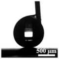
图4b为本发明一个实施例的所述超疏冷凝水表面对300um尺度的冷凝水滴的超疏水示意图;4b is a schematic diagram of superhydrophobicity of the superhydrophobic condensed water surface to 300um-scale condensed water droplets according to an embodiment of the present invention;
图4c为本发明一个实施例的所述超疏冷凝水表面对200um尺度的冷凝水滴的超疏水示意图;4c is a schematic diagram of superhydrophobicity of the superhydrophobic condensed water surface to 200um-scale condensed water droplets according to an embodiment of the present invention;
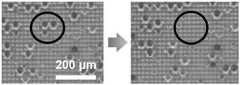
图4d为本发明一个实施例的冷凝水自移除的过程示意图。FIG. 4d is a schematic diagram of a process of self-removal of condensed water according to an embodiment of the present invention.
具体实施方式Detailed ways
下面将结合本发明实施例中的附图,对本发明实施例中的技术方案进行清楚、完整地描述,显然,所描述的实施例仅仅是本发明一部分实施例,而不是全部的实施例。基于本发明中的实施例,本领域普通技术人员在没有付出创造性劳动前提下所获得的所有其他实施例,都属于本发明保护的范围。The technical solutions in the embodiments of the present invention will be clearly and completely described below with reference to the accompanying drawings in the embodiments of the present invention. Obviously, the described embodiments are only a part of the embodiments of the present invention, but not all of the embodiments. Based on the embodiments of the present invention, all other embodiments obtained by those of ordinary skill in the art without creative efforts shall fall within the protection scope of the present invention.
需要说明的是,本说明书实施例及附图中的术语“包括”和“具有”以及它们任何变形,意图在于覆盖不排他的包含。例如包含了一系列步骤或单元的过程、方法、系统、产品或设备没有限定于已列出的步骤或单元,而是可选地还包括没有列出的步骤或单元,或可选地还包括对于这些过程、方法、产品或设备固有的其它步骤或单元。It should be noted that the terms "comprising" and "having" in the embodiments of the present specification and the accompanying drawings, as well as any modifications thereof, are intended to cover non-exclusive inclusion. For example, a process, method, system, product or device comprising a series of steps or units is not limited to the listed steps or units, but optionally also includes unlisted steps or units, or optionally also includes For other steps or units inherent to these processes, methods, products or devices.
本说明书实施例公开了一种超疏冷凝水表面及其制备方法、电池极板和燃料电池。以下分别进行详细说明。The embodiments of this specification disclose a superphobic condensed water surface and a preparation method thereof, a battery electrode plate and a fuel cell. Each of them will be described in detail below.
图2为本发明一个实施例的超疏冷凝水表面的制备方法流程图;如图2所示,该制备方法包括以下步骤:Fig. 2 is the flow chart of the preparation method of the superphobic condensed water surface of an embodiment of the present invention; As shown in Fig. 2, this preparation method comprises the following steps:
S210,在真空腔体中设置有燃料电池极板以及石墨靶材,其中,所述燃料电池极板设置在所述石墨靶材的上方;S210, a fuel cell electrode plate and a graphite target material are arranged in the vacuum cavity, wherein the fuel cell electrode plate is arranged above the graphite target material;
S220,将所述真空腔体的气压值降低至10-3Pa至3×10⁻⁴Pa后,充入氩气;在一种实现方式中,将真空腔体的气压值降低至预设气压值再充入惰性气体氩气,氩气更稳定,更有利于以下多孔石墨薄膜层的形成。S220, after reducing the air pressure value of the vacuum chamber to 10-3 Pa to 3×10⁻⁴ Pa, fill with argon; in an implementation manner, reduce the air pressure value of the vacuum chamber to a preset air pressure The value is then filled with inert gas argon, which is more stable and more conducive to the formation of the following porous graphite thin film layer.
S230,向所述石墨靶材发射脉冲激光束轰击所述石墨靶材,以产生石墨等离子体,其中,所述脉冲激光束的每个脉冲具有800fs至12ps的脉宽,且所述脉冲激光束的直径为120um;S230, emitting a pulsed laser beam to the graphite target to bombard the graphite target to generate graphite plasma, wherein each pulse of the pulsed laser beam has a pulse width of 800fs to 12ps, and the pulsed laser beam The diameter is 120um;
脉冲激光束的每个脉冲的脉宽越小,得到的多孔石墨薄膜层的多孔结构的孔越小,越有利于应对燃料电池运行环境下的冷凝水。The smaller the pulse width of each pulse of the pulsed laser beam, the smaller the pores of the porous structure of the obtained porous graphite thin film layer, which is more favorable for coping with condensed water in the operating environment of the fuel cell.
S240,所述石墨等离子体与充入的氩气碰撞并在所述燃料电池极板上沉积,形成由纳米级石墨颗粒组成的多孔石墨薄膜层;S240, the graphite plasma collides with the charged argon gas and is deposited on the fuel cell electrode plate to form a porous graphite thin film layer composed of nanoscale graphite particles;
S250,利用气相沉积方法在所述多孔石墨薄膜层上形成硅烷疏水涂层,以得到超疏冷凝水表面。S250, using a vapor deposition method to form a silane hydrophobic coating on the porous graphite thin film layer to obtain a superphobic condensed water surface.
图3a为本发明一个实施例的真空腔体、燃料电池极板和石墨靶材的连接示意图。如图3a所示,将燃料电池极板设置在真空腔体的顶部,将石墨靶材设置在燃料电池极板下方,向石墨靶材发射脉冲激光束,利用超快脉冲激光沉积技术,在燃料电池极板的流场表面形成多孔石墨薄膜层。Fig. 3a is a schematic diagram of the connection of a vacuum chamber, a fuel cell electrode plate and a graphite target according to an embodiment of the present invention. As shown in Figure 3a, the fuel cell electrode plate is placed on the top of the vacuum chamber, the graphite target is placed under the fuel cell electrode plate, and a pulsed laser beam is emitted to the graphite target. A porous graphite thin film layer is formed on the surface of the flow field of the battery plate.
图3b为本发明一个实施例的利用气相沉积方法在所述多孔石墨薄膜层上形成硅烷疏水涂层的过程示意图。如图3b所示,通过气相沉积,在多孔石墨薄膜层上形成硅烷疏水涂层,该硅烷疏水涂层使得多孔薄膜层的表面浸润特征由超亲水变为超疏水。3b is a schematic diagram of a process of forming a silane hydrophobic coating on the porous graphite thin film layer by a vapor deposition method according to an embodiment of the present invention. As shown in Figure 3b, a silane hydrophobic coating was formed on the porous graphite thin film layer by vapor deposition, and the silane hydrophobic coating changed the surface wetting characteristics of the porous thin film layer from superhydrophilic to superhydrophobic.
上述实施例的超疏冷凝水表面的制备方法通过脉冲激光束轰击设置在真空腔体中的石墨靶材,石墨靶材气化扩散,与真空腔体的氩气的碰撞减速,最终沉积在设置在石墨靶材上方的燃料电池基板的流场结构上,形成了由纳米级的石墨颗粒组成的多孔石墨薄膜层,该多孔石墨薄膜层的纳米级的多孔结构结合通过气相沉积方法得到的硅烷疏水涂层,一方面纳米级的多孔结构更容易形成超疏冷凝水表面,更能有效的针对本身就较小的冷凝水进行疏水,另一方面,纳米级的多孔石墨结构再结合硅烷疏水涂层所得的表面对于水滴的拉普拉斯力不大于毛细力,从而使得冷凝水难以浸润,实现对冷凝水的超疏。将该方法制备的表面引入到燃料电池双极板的流场设计和制备当中,能够让燃料电池双极板流场在低运行温度、高加湿和高电流密度的工作条件仍然可以维持有效的排水性能,避免水淹现象。In the preparation method of the superphobic condensed water surface of the above-mentioned embodiment, the graphite target material arranged in the vacuum cavity is bombarded by a pulsed laser beam, the graphite target material is vaporized and diffused, collided with the argon gas in the vacuum cavity to decelerate, and finally deposited in the setting material. On the flow field structure of the fuel cell substrate above the graphite target, a porous graphite thin film layer composed of nanoscale graphite particles is formed. The nanoscale porous structure of the porous graphite thin film layer is combined with the hydrophobic silane obtained by the vapor deposition method. Coating, on the one hand, the nano-scale porous structure is easier to form a super-hydrophobic condensed water surface, and it can more effectively hydrophobicize the small condensed water itself. On the other hand, the nano-scale porous graphite structure is combined with a silane hydrophobic coating. The Laplace force of the resulting surface for water droplets is not greater than the capillary force, which makes it difficult for condensed water to infiltrate and achieves superphobicity to condensed water. The surface prepared by this method is introduced into the design and preparation of the flow field of the fuel cell bipolar plate, so that the flow field of the fuel cell bipolar plate can still maintain effective drainage under the working conditions of low operating temperature, high humidification and high current density performance and avoid flooding.
一种实现方式中,所述利用气相沉积方法在所述多孔石墨薄膜层上形成硅烷疏水涂层,具体包括:In an implementation manner, forming a silane hydrophobic coating on the porous graphite thin film layer by a vapor deposition method specifically includes:
将沉积有所述多孔石墨薄膜层的燃料电池极板放至另一容器中,并在所述容器中滴入氟硅烷,然后对所述容器进行抽真空,使所述氟硅烷通过气相沉积方法沉积在所述多孔石墨薄膜层上,最后在温度为预设温度的烘箱里放置预设时间,以形成硅烷疏水涂层。Put the fuel cell electrode plate on which the porous graphite thin film layer is deposited into another container, drop fluorosilane into the container, and then evacuate the container to make the fluorosilane pass through the vapor deposition method Deposited on the porous graphite thin film layer, and finally placed in an oven with a preset temperature for a preset time to form a silane hydrophobic coating.
一种实现方式中,所述石墨颗粒为纳米颗粒,所述纳米颗粒的纳米结构尺度为100nm。In an implementation manner, the graphite particles are nanoparticles, and the nanostructure dimension of the nanoparticles is 100 nm.
一种实现方式中,所述多孔石墨薄膜层的厚度为1um至5um。In an implementation manner, the thickness of the porous graphite thin film layer is 1 um to 5 um.
一种实现方式中,向所述真空腔体内充入的氩气的气压为10Pa至50Pa,以保证多孔薄膜层的孔隙率和石墨颗粒的平均粒径满足拉普拉斯力不大于毛细力的需求,优选的孔隙率为30%至80%,颗粒的平均尺寸为1um至20um。In an implementation manner, the air pressure of the argon gas filled into the vacuum chamber is 10Pa to 50Pa, so as to ensure that the porosity of the porous film layer and the average particle size of the graphite particles satisfy the Laplace force not greater than the capillary force. Requirements, the preferred porosity is 30% to 80%, and the average particle size is 1um to 20um.
通过脉冲激光束轰击设置在真空腔体中的石墨靶材,使石墨靶材气化扩散与真空腔体充入的氩气的碰撞减速,并设置脉冲激光束的每个脉冲具有800fs至12ps的脉宽,且所述脉冲激光束的直径为120um,气化后的石墨等离子体最终沉积在设置在石墨靶材上方的燃料电池基板的流场结构上,形成了由纳米级的石墨颗粒组成的多孔石墨薄膜层,进一步的充入的氩气的气压为10Pa至50Pa,此气压可保证多孔石墨薄膜层的孔隙率和石墨颗粒的平均粒径在一个合适的区间,比如,孔隙率为30%至80%,石墨颗粒的平均尺寸为1um至20um,以保证形成的多孔结构更有利于拉普拉斯力和毛细力的平衡。The graphite target set in the vacuum cavity is bombarded by the pulsed laser beam, so that the gasification and diffusion of the graphite target material and the collision of the argon gas filled in the vacuum cavity are decelerated, and each pulse of the pulsed laser beam is set to have 800fs to 12ps. The pulse width, and the diameter of the pulsed laser beam is 120um, the gasified graphite plasma is finally deposited on the flow field structure of the fuel cell substrate arranged above the graphite target, forming a nanoscale graphite particle. For the porous graphite thin film layer, the gas pressure of the argon gas to be filled is 10Pa to 50Pa, which can ensure that the porosity of the porous graphite thin film layer and the average particle size of the graphite particles are in a suitable range, for example, the porosity is 30% To 80%, the average size of the graphite particles is 1um to 20um, to ensure that the formed porous structure is more conducive to the balance of Laplace force and capillary force.
一种实现方式中,所述向所述石墨靶材发射脉冲激光束轰击所述石墨靶材,在所述燃料电池极板上沉积石墨等离子体,还包括:所述激光束的平均输出功率为50W至200W,脉冲频率为100kHz至1000kHz,靶基距为25mm至50mm,沉积时间为5分钟。In an implementation manner, the firing of a pulsed laser beam to the graphite target to bombard the graphite target, and the deposition of graphite plasma on the fuel cell electrode plate, further includes: the average output power of the laser beam is: 50W to 200W, pulse frequency of 100kHz to 1000kHz, target base distance of 25mm to 50mm, deposition time of 5 minutes.
在本说明书另一实施例中,还提供了一种超疏冷凝水表面,所述超疏冷凝水表面采用如上述任一方法实施例中所述的超疏冷凝水表面的制备方法制备而成,该超疏冷凝水表面包括:沉积在燃料电池双极板上的多孔石墨薄膜层以及设置在所述多孔石墨薄膜层上的硅烷疏水涂层。In another embodiment of the present specification, a superphobic condensed water surface is also provided, and the superhydrophobic condensed water surface is prepared by the method for preparing a superphobic condensed water surface as described in any of the above method embodiments. , the super-hydrophobic condensed water surface includes: a porous graphite thin film layer deposited on a fuel cell bipolar plate and a silane hydrophobic coating disposed on the porous graphite thin film layer.
多孔薄膜层由粒径为百纳米级别纳米颗粒组成,纳米结构尺度为100nm左右,为较优的超疏冷凝水表面的结构参数。多孔薄膜层的厚度为1-5微米。图4a为本发明一个实施例的所述超疏冷凝水表面的超疏水性能示意图,图4d为本发明一个实施例的冷凝水自移除的过程示意图,如图4a所示,经过疏水处理后的多孔薄膜层表面具备优越的超疏水性能,5uL(或3uL)的水滴接触角大于150°而滚动角小于3°。图4b为本发明一个实施例的所述超疏冷凝水表面对300um尺度的冷凝水滴的超疏水示意图,图4c为本发明一个实施例的所述超疏冷凝水表面对200um尺度的冷凝水滴的超疏水示意图,图4d为本发明一个实施例的冷凝水自移除的过程示意图,如图4d所示,两个微米级水滴在合并的过程中,水滴之间的液桥撞击表面发生水滴弹跳现象,并在2.23毫秒的时间内完成水滴从表面的自移除。如图4b、图4c和图4d所示,该表面可对微米尺度的冷凝水滴超疏,而且冷凝水可通过合并,将表面能转化为动能,引发冷凝水滴从表面自移除,从而解决冷凝水导致双极板阴极流场表面疏水失效的问题。The porous film layer is composed of nanoparticles with a particle size of 100 nanometers, and the nanostructure size is about 100 nm, which is an excellent structural parameter of the superphobic condensed water surface. The thickness of the porous film layer is 1-5 microns. FIG. 4a is a schematic diagram of the superhydrophobicity performance of the superphobic condensed water surface according to an embodiment of the present invention, and FIG. 4d is a schematic diagram of the process of self-removal of the condensed water according to an embodiment of the present invention. As shown in FIG. 4a, after hydrophobic treatment The surface of the porous film layer has excellent superhydrophobic properties, the contact angle of 5uL (or 3uL) water droplets is greater than 150° and the rolling angle is less than 3°. FIG. 4b is a schematic diagram of superhydrophobicity of the superhydrophobic condensed water surface to condensed water droplets with a scale of 300 um according to an embodiment of the present invention, and FIG. Schematic diagram of superhydrophobicity. Figure 4d is a schematic diagram of the process of self-removal of condensed water according to an embodiment of the present invention. As shown in Figure 4d, in the process of merging two micron-sized water droplets, the liquid bridge between the water droplets hits the surface and the water droplet bounces phenomenon and complete the self-removal of water droplets from the surface within 2.23 milliseconds. As shown in Figure 4b, Figure 4c, and Figure 4d, the surface can be superphobic to micron-scale condensed water droplets, and the condensed water can convert the surface energy into kinetic energy by merging, causing the condensed water droplets to self-remove from the surface, thereby solving the condensation problem Water causes the hydrophobic failure of the bipolar plate cathode flow field surface.
在本说明书另一实施例中,还提供了一种燃料电池极板,所述燃料电池极板上设有采用如上述实施例所述的超疏冷凝水表面。In another embodiment of the present specification, a fuel cell electrode plate is also provided, and the fuel cell electrode plate is provided with the superphobic condensed water surface described in the above embodiment.
在本说明书另一实施例中,还提供了一种燃料电池,包括如上面实施例所述的燃料电池极板。In another embodiment of the present specification, a fuel cell is also provided, comprising the fuel cell electrode plate described in the above embodiment.
本领域普通技术人员可以理解:附图只是一个实施例的示意图,附图中的模块或流程并不一定是实施本发明所必须的。Those of ordinary skill in the art can understand that the accompanying drawing is only a schematic diagram of an embodiment, and the modules or processes in the accompanying drawing are not necessarily necessary to implement the present invention.
本领域普通技术人员可以理解:实施例中的装置中的模块可以按照实施例描述分布于实施例的装置中,也可以进行相应变化位于不同于本实施例的一个或多个装置中。上述实施例的模块可以合并为一个模块,也可以进一步拆分成多个子模块。Those skilled in the art may understand that: the modules in the apparatus in the embodiment may be distributed in the apparatus in the embodiment according to the description of the embodiment, and may also be located in one or more apparatuses different from this embodiment with corresponding changes. The modules in the foregoing embodiments may be combined into one module, or may be further split into multiple sub-modules.
最后应说明的是:以上实施例仅用以说明本发明的技术方案,而非对其限制;尽管参照前述实施例对本发明进行了详细的说明,本领域的普通技术人员应当理解:其依然可以对前述实施例所记载的技术方案进行修改,或者对其中部分技术特征进行等同替换;而这些修改或者替换,并不使相应技术方案的本质脱离本发明实施例技术方案的精神和范围。Finally, it should be noted that the above embodiments are only used to illustrate the technical solutions of the present invention, but not to limit them; although the present invention has been described in detail with reference to the foregoing embodiments, those of ordinary skill in the art should understand that it can still be The technical solutions described in the foregoing embodiments are modified, or some technical features thereof are equivalently replaced; and these modifications or replacements do not make the essence of the corresponding technical solutions deviate from the spirit and scope of the technical solutions in the embodiments of the present invention.
Claims (9)
Priority Applications (1)
| Application Number | Priority Date | Filing Date | Title |
|---|---|---|---|
| CN202210629199.9ACN114843543A (en) | 2022-06-01 | 2022-06-01 | A superhydrophobic condensed water surface and preparation method thereof, battery electrode plate and fuel cell |
Applications Claiming Priority (1)
| Application Number | Priority Date | Filing Date | Title |
|---|---|---|---|
| CN202210629199.9ACN114843543A (en) | 2022-06-01 | 2022-06-01 | A superhydrophobic condensed water surface and preparation method thereof, battery electrode plate and fuel cell |
Publications (1)
| Publication Number | Publication Date |
|---|---|
| CN114843543Atrue CN114843543A (en) | 2022-08-02 |
Family
ID=82574633
Family Applications (1)
| Application Number | Title | Priority Date | Filing Date |
|---|---|---|---|
| CN202210629199.9APendingCN114843543A (en) | 2022-06-01 | 2022-06-01 | A superhydrophobic condensed water surface and preparation method thereof, battery electrode plate and fuel cell |
Country Status (1)
| Country | Link |
|---|---|
| CN (1) | CN114843543A (en) |
Citations (7)
| Publication number | Priority date | Publication date | Assignee | Title |
|---|---|---|---|---|
| KR20050090876A (en)* | 2004-03-10 | 2005-09-14 | (주)퓨얼셀 파워 | Separator for fuel cell and manufacturing method thereof, and fuel cell having such a separator |
| US20080102347A1 (en)* | 2006-10-31 | 2008-05-01 | Gm Global Technology Operations, Inc. | Super-hydrophobic composite bipolar plate |
| US20090169871A1 (en)* | 2006-02-23 | 2009-07-02 | Reijo Lappalainen | Method for Producing High-Quality Surfaces and a Product Having a High-Quality Surface |
| CN101962769A (en)* | 2010-10-08 | 2011-02-02 | 中国航空工业集团公司北京航空制造工程研究所 | Method for preparing hydrophobic film on surface of material |
| CN102760897A (en)* | 2011-04-29 | 2012-10-31 | 现代自动车株式会社 | Porous medium with increased hydrophobicity and method of manufacturing the same |
| US20160226065A1 (en)* | 2015-01-29 | 2016-08-04 | Board Of Trustees Of The University Of Arkansas | Density modulated thin film electrodes, methods of making same, and applications of same |
| CN114248001A (en)* | 2021-07-08 | 2022-03-29 | 冠驰新能科技(南京)有限公司 | Laser processing system for regulating and controlling wettability of bipolar plate flow channel |
- 2022
- 2022-06-01CNCN202210629199.9Apatent/CN114843543A/enactivePending
Patent Citations (8)
| Publication number | Priority date | Publication date | Assignee | Title |
|---|---|---|---|---|
| KR20050090876A (en)* | 2004-03-10 | 2005-09-14 | (주)퓨얼셀 파워 | Separator for fuel cell and manufacturing method thereof, and fuel cell having such a separator |
| US20090169871A1 (en)* | 2006-02-23 | 2009-07-02 | Reijo Lappalainen | Method for Producing High-Quality Surfaces and a Product Having a High-Quality Surface |
| US20080102347A1 (en)* | 2006-10-31 | 2008-05-01 | Gm Global Technology Operations, Inc. | Super-hydrophobic composite bipolar plate |
| CN101962769A (en)* | 2010-10-08 | 2011-02-02 | 中国航空工业集团公司北京航空制造工程研究所 | Method for preparing hydrophobic film on surface of material |
| CN102760897A (en)* | 2011-04-29 | 2012-10-31 | 现代自动车株式会社 | Porous medium with increased hydrophobicity and method of manufacturing the same |
| DE102011081627A1 (en)* | 2011-04-29 | 2012-10-31 | Hyundai Motor Co. | Porous medium with increased hydrophobicity and method for producing the same |
| US20160226065A1 (en)* | 2015-01-29 | 2016-08-04 | Board Of Trustees Of The University Of Arkansas | Density modulated thin film electrodes, methods of making same, and applications of same |
| CN114248001A (en)* | 2021-07-08 | 2022-03-29 | 冠驰新能科技(南京)有限公司 | Laser processing system for regulating and controlling wettability of bipolar plate flow channel |
Non-Patent Citations (1)
| Title |
|---|
| R.FERNANDES等: ""Ruthenium nanoparticles supported over carbon thin film catalyst synthesized by pulsed laser deposition for hydrogen production from ammonia boran"", 《APPLIED CATALYSIS A:GENERAL》, no. 495, pages 23 - 29, XP029124251, DOI: 10.1016/j.apcata.2015.01.034* |
Similar Documents
| Publication | Publication Date | Title |
|---|---|---|
| CN101582516B (en) | Bipolar plate with inelt and ouelt water management features | |
| CN101546834B (en) | Method of coating fuel cell components for water removal | |
| JP5193039B2 (en) | Hydrophilic coating for fuel cell bipolar plates and method of making the same | |
| CN108574107A (en) | Method for Improving Conductivity and Corrosion Resistance of Fuel Cell Bipolar Plate Carbide Coating | |
| KR100599774B1 (en) | Membrane / electrode assembly for fuel cell, manufacturing method thereof and fuel cell comprising same | |
| CN103474256A (en) | Current collector subjected to surface modification by vertically-oriented graphene and preparation method thereof | |
| WO2006118346A1 (en) | Hydrophobic catalyst layer for solid polymer fuel cell, method for producing same, solid polymer fuel cell and method for manufacturing same | |
| CN101402095A (en) | Plasma surface cleaning apparatus | |
| US8182884B2 (en) | Process for application of a hydrophilic coating to fuel cell bipolar plates | |
| WO2021068575A1 (en) | Modified separator of metal negative electrode battery, preparation method and application | |
| CN110614742A (en) | Microporous layer with surface hydrophilic and hydrophobic characteristics alternately distributed, mold and preparation method thereof | |
| CN100487968C (en) | Fuel cell battery with large active surface and reduced volume and manufacturing method thereof | |
| CN113346044B (en) | Battery material and preparation method thereof | |
| KR20190019520A (en) | Manufacuring method of polymer fuel cell electrode using electrospraying and polymer fuel cell electrode using the same | |
| TWI353680B (en) | Fuel cell conditioning layer | |
| CN114023986B (en) | Composite coating for fuel cell titanium substrate bipolar plate and preparation method thereof | |
| CN106654290B (en) | Multistage stepped hole structure water transport plate and its preparation | |
| CN114843543A (en) | A superhydrophobic condensed water surface and preparation method thereof, battery electrode plate and fuel cell | |
| JP2008300195A (en) | Method for producing diffusion layer for fuel cell and method for producing fuel cell | |
| CN102306804B (en) | High-sp2 hybridization compact carbon coating layer for proton exchange membrane fuel cell bipolar plate and preparation method of high-sp2 hybridization compact carbon coating layer | |
| CN118352583A (en) | Method for preparing porous proton exchange membrane for flow battery by using acid etching technology | |
| CN115275087B (en) | A method for processing a pole piece, a pole piece processing device and a negative pole piece | |
| CN110034311B (en) | Preparation method of bipolar plate and bipolar plate | |
| JP2009505354A (en) | Method for applying a hydrophilic coating to a fuel cell bipolar plate | |
| US20240088405A1 (en) | Method for forming a hydrophilic surface on a graphite-containing material, and method for manufacturing a bipolar plate, and bipolar plate, and fuel cell or flow battery having such a bipolar plate |
Legal Events
| Date | Code | Title | Description |
|---|---|---|---|
| PB01 | Publication | ||
| PB01 | Publication | ||
| SE01 | Entry into force of request for substantive examination | ||
| SE01 | Entry into force of request for substantive examination | ||
| RJ01 | Rejection of invention patent application after publication | ||
| RJ01 | Rejection of invention patent application after publication | Application publication date:20220802 |