CN114828766A - Catheter deflection control assembly - Google Patents
Catheter deflection control assemblyDownload PDFInfo
- Publication number
- CN114828766A CN114828766ACN202080087345.9ACN202080087345ACN114828766ACN 114828766 ACN114828766 ACN 114828766ACN 202080087345 ACN202080087345 ACN 202080087345ACN 114828766 ACN114828766 ACN 114828766A
- Authority
- CN
- China
- Prior art keywords
- assembly
- rack
- pinion
- end effector
- locking
- Prior art date
- Legal status (The legal status is an assumption and is not a legal conclusion. Google has not performed a legal analysis and makes no representation as to the accuracy of the status listed.)
- Pending
Links
Images


Classifications
- A—HUMAN NECESSITIES
- A61—MEDICAL OR VETERINARY SCIENCE; HYGIENE
- A61B—DIAGNOSIS; SURGERY; IDENTIFICATION
- A61B18/00—Surgical instruments, devices or methods for transferring non-mechanical forms of energy to or from the body
- A61B18/04—Surgical instruments, devices or methods for transferring non-mechanical forms of energy to or from the body by heating
- A61B18/12—Surgical instruments, devices or methods for transferring non-mechanical forms of energy to or from the body by heating by passing a current through the tissue to be heated, e.g. high-frequency current
- A61B18/14—Probes or electrodes therefor
- A61B18/1492—Probes or electrodes therefor having a flexible, catheter-like structure, e.g. for heart ablation
- A—HUMAN NECESSITIES
- A61—MEDICAL OR VETERINARY SCIENCE; HYGIENE
- A61B—DIAGNOSIS; SURGERY; IDENTIFICATION
- A61B34/00—Computer-aided surgery; Manipulators or robots specially adapted for use in surgery
- A61B34/70—Manipulators specially adapted for use in surgery
- A61B34/71—Manipulators operated by drive cable mechanisms
- A—HUMAN NECESSITIES
- A61—MEDICAL OR VETERINARY SCIENCE; HYGIENE
- A61B—DIAGNOSIS; SURGERY; IDENTIFICATION
- A61B17/00—Surgical instruments, devices or methods
- A61B17/00234—Surgical instruments, devices or methods for minimally invasive surgery
- A61B2017/00292—Surgical instruments, devices or methods for minimally invasive surgery mounted on or guided by flexible, e.g. catheter-like, means
- A61B2017/003—Steerable
- A61B2017/00318—Steering mechanisms
- A61B2017/00323—Cables or rods
- A—HUMAN NECESSITIES
- A61—MEDICAL OR VETERINARY SCIENCE; HYGIENE
- A61B—DIAGNOSIS; SURGERY; IDENTIFICATION
- A61B18/00—Surgical instruments, devices or methods for transferring non-mechanical forms of energy to or from the body
- A61B2018/00315—Surgical instruments, devices or methods for transferring non-mechanical forms of energy to or from the body for treatment of particular body parts
- A61B2018/00345—Vascular system
- A61B2018/00351—Heart
- A—HUMAN NECESSITIES
- A61—MEDICAL OR VETERINARY SCIENCE; HYGIENE
- A61B—DIAGNOSIS; SURGERY; IDENTIFICATION
- A61B18/00—Surgical instruments, devices or methods for transferring non-mechanical forms of energy to or from the body
- A61B2018/00571—Surgical instruments, devices or methods for transferring non-mechanical forms of energy to or from the body for achieving a particular surgical effect
- A61B2018/00577—Ablation
- A—HUMAN NECESSITIES
- A61—MEDICAL OR VETERINARY SCIENCE; HYGIENE
- A61B—DIAGNOSIS; SURGERY; IDENTIFICATION
- A61B18/00—Surgical instruments, devices or methods for transferring non-mechanical forms of energy to or from the body
- A61B2018/00636—Sensing and controlling the application of energy
- A61B2018/00773—Sensed parameters
- A61B2018/00791—Temperature
- A61B2018/00821—Temperature measured by a thermocouple
- A—HUMAN NECESSITIES
- A61—MEDICAL OR VETERINARY SCIENCE; HYGIENE
- A61B—DIAGNOSIS; SURGERY; IDENTIFICATION
- A61B18/00—Surgical instruments, devices or methods for transferring non-mechanical forms of energy to or from the body
- A61B2018/00636—Sensing and controlling the application of energy
- A61B2018/00773—Sensed parameters
- A61B2018/00839—Bioelectrical parameters, e.g. ECG, EEG
- A—HUMAN NECESSITIES
- A61—MEDICAL OR VETERINARY SCIENCE; HYGIENE
- A61B—DIAGNOSIS; SURGERY; IDENTIFICATION
- A61B18/00—Surgical instruments, devices or methods for transferring non-mechanical forms of energy to or from the body
- A61B2018/00636—Sensing and controlling the application of energy
- A61B2018/00898—Alarms or notifications created in response to an abnormal condition
- A—HUMAN NECESSITIES
- A61—MEDICAL OR VETERINARY SCIENCE; HYGIENE
- A61B—DIAGNOSIS; SURGERY; IDENTIFICATION
- A61B18/00—Surgical instruments, devices or methods for transferring non-mechanical forms of energy to or from the body
- A61B2018/00636—Sensing and controlling the application of energy
- A61B2018/00904—Automatic detection of target tissue
- A—HUMAN NECESSITIES
- A61—MEDICAL OR VETERINARY SCIENCE; HYGIENE
- A61B—DIAGNOSIS; SURGERY; IDENTIFICATION
- A61B18/00—Surgical instruments, devices or methods for transferring non-mechanical forms of energy to or from the body
- A61B2018/0091—Handpieces of the surgical instrument or device
- A—HUMAN NECESSITIES
- A61—MEDICAL OR VETERINARY SCIENCE; HYGIENE
- A61B—DIAGNOSIS; SURGERY; IDENTIFICATION
- A61B18/00—Surgical instruments, devices or methods for transferring non-mechanical forms of energy to or from the body
- A61B2018/0091—Handpieces of the surgical instrument or device
- A61B2018/00916—Handpieces of the surgical instrument or device with means for switching or controlling the main function of the instrument or device
- A—HUMAN NECESSITIES
- A61—MEDICAL OR VETERINARY SCIENCE; HYGIENE
- A61B—DIAGNOSIS; SURGERY; IDENTIFICATION
- A61B34/00—Computer-aided surgery; Manipulators or robots specially adapted for use in surgery
- A61B34/20—Surgical navigation systems; Devices for tracking or guiding surgical instruments, e.g. for frameless stereotaxis
- A61B2034/2046—Tracking techniques
- A61B2034/2051—Electromagnetic tracking systems
- A—HUMAN NECESSITIES
- A61—MEDICAL OR VETERINARY SCIENCE; HYGIENE
- A61B—DIAGNOSIS; SURGERY; IDENTIFICATION
- A61B2218/00—Details of surgical instruments, devices or methods for transferring non-mechanical forms of energy to or from the body
- A61B2218/001—Details of surgical instruments, devices or methods for transferring non-mechanical forms of energy to or from the body having means for irrigation and/or aspiration of substances to and/or from the surgical site
- A61B2218/002—Irrigation
- A—HUMAN NECESSITIES
- A61—MEDICAL OR VETERINARY SCIENCE; HYGIENE
- A61B—DIAGNOSIS; SURGERY; IDENTIFICATION
- A61B2562/00—Details of sensors; Constructional details of sensor housings or probes; Accessories for sensors
- A61B2562/02—Details of sensors specially adapted for in-vivo measurements
- A61B2562/0223—Magnetic field sensors
- A—HUMAN NECESSITIES
- A61—MEDICAL OR VETERINARY SCIENCE; HYGIENE
- A61B—DIAGNOSIS; SURGERY; IDENTIFICATION
- A61B2562/00—Details of sensors; Constructional details of sensor housings or probes; Accessories for sensors
- A61B2562/02—Details of sensors specially adapted for in-vivo measurements
- A61B2562/0261—Strain gauges
- A—HUMAN NECESSITIES
- A61—MEDICAL OR VETERINARY SCIENCE; HYGIENE
- A61M—DEVICES FOR INTRODUCING MEDIA INTO, OR ONTO, THE BODY; DEVICES FOR TRANSDUCING BODY MEDIA OR FOR TAKING MEDIA FROM THE BODY; DEVICES FOR PRODUCING OR ENDING SLEEP OR STUPOR
- A61M25/00—Catheters; Hollow probes
- A61M25/01—Introducing, guiding, advancing, emplacing or holding catheters
- A61M25/0105—Steering means as part of the catheter or advancing means; Markers for positioning
- A61M25/0133—Tip steering devices
- A61M25/0136—Handles therefor
- A—HUMAN NECESSITIES
- A61—MEDICAL OR VETERINARY SCIENCE; HYGIENE
- A61M—DEVICES FOR INTRODUCING MEDIA INTO, OR ONTO, THE BODY; DEVICES FOR TRANSDUCING BODY MEDIA OR FOR TAKING MEDIA FROM THE BODY; DEVICES FOR PRODUCING OR ENDING SLEEP OR STUPOR
- A61M25/00—Catheters; Hollow probes
- A61M25/01—Introducing, guiding, advancing, emplacing or holding catheters
- A61M25/0105—Steering means as part of the catheter or advancing means; Markers for positioning
- A61M25/0133—Tip steering devices
- A61M25/0147—Tip steering devices with movable mechanical means, e.g. pull wires
Landscapes
- Health & Medical Sciences (AREA)
- Surgery (AREA)
- Engineering & Computer Science (AREA)
- Life Sciences & Earth Sciences (AREA)
- Animal Behavior & Ethology (AREA)
- General Health & Medical Sciences (AREA)
- Biomedical Technology (AREA)
- Heart & Thoracic Surgery (AREA)
- Medical Informatics (AREA)
- Molecular Biology (AREA)
- Nuclear Medicine, Radiotherapy & Molecular Imaging (AREA)
- Veterinary Medicine (AREA)
- Public Health (AREA)
- Cardiology (AREA)
- Physics & Mathematics (AREA)
- Plasma & Fusion (AREA)
- Otolaryngology (AREA)
- Robotics (AREA)
- Surgical Instruments (AREA)
- Media Introduction/Drainage Providing Device (AREA)
Abstract
Description
Translated fromChinese背景技术Background technique
当心脏组织的区域异常地传导电信号时,发生心律失常,诸如心房纤颤。用于治疗心律失常的规程包括外科中断用于此类信号的传导通路。通过施加能量(例如,射频(RF)能量)来选择性地消融心脏组织,可能停止或改变不需要的电信号从心脏的一部分到另一部分的传播。消融过程可通过形成电绝缘病灶或疤痕组织来提供对不需要的电通路的阻隔,该电绝缘病灶或疤痕组织有效地阻断异常电信号跨组织的通信。Arrhythmias, such as atrial fibrillation, occur when areas of heart tissue conduct electrical signals abnormally. Procedures for the treatment of cardiac arrhythmias include surgical interruption of conduction pathways for such signals. Selectively ablating cardiac tissue by applying energy (eg, radio frequency (RF) energy) may stop or alter the propagation of unwanted electrical signals from one part of the heart to another. The ablation process can provide a block to unwanted electrical pathways by forming electrically insulating lesions or scar tissue that effectively block the communication of abnormal electrical signals across the tissue.
在一些规程中,具有一个或多个RF电极的导管可用于提供心血管系统内的消融。导管可被插入到主要静脉或动脉(例如,股动脉)中,并且然后推进以将电极定位在心脏内或与心脏相邻的心血管结构(例如,肺静脉)中。一个或多个电极可被放置成与心脏组织或其他血管组织接触,并且然后利用RF能量激活,从而消融所接触的组织。在一些情况下,电极可以是双极性的。在一些其他情况下,单极电极可与同患者接触的接地焊盘或其他参考电极结合使用。冲洗可用于从消融导管的消融部件吸热;并且防止在消融位点附近形成血块。In some procedures, a catheter with one or more RF electrodes may be used to provide ablation within the cardiovascular system. A catheter can be inserted into a major vein or artery (eg, femoral artery) and then advanced to position electrodes within the heart or in cardiovascular structures adjacent to the heart (eg, pulmonary veins). One or more electrodes may be placed in contact with cardiac tissue or other vascular tissue, and then activated with RF energy, thereby ablating the contacted tissue. In some cases, the electrodes may be bipolar. In some other cases, monopolar electrodes may be used in conjunction with ground pads or other reference electrodes in contact with the patient. Irrigation can be used to absorb heat from the ablation components of the ablation catheter; and to prevent blood clots from forming near the ablation site.
消融导管的示例在以下文献中有所描述:2013年1月31日公布的名称为“Integrated Ablation System using Catheter with Multiple Irrigation Lumens”的美国公布号2013/0030426,其公开内容以引用方式全文并入本文;2017年11月2日公布的名称为“Irrigated Balloon Catheter with Flexible Circuit Electrode Assembly”的美国公布号2017/0312022,其公开内容以引用方式全文并入本文;2018年3月1日公布的名称为“Catheter with Bipole Electrode Spacer and Related Methods”的美国公布号2018/0056038,其公开内容以引用方式全文并入本文;2018年11月20日公布的名称为“Catheter with Soft Distal Tip for Mapping and Ablating Tubular Region”的美国专利号10,130,422,其公开内容以引用方式全文并入本文;以及2017年10月31日公布的名称为“Electrocardiogram Noise Reduction”的美国专利号9,801,585,其公开内容以引用方式全文并入本文。Examples of ablation catheters are described in US Publication No. 2013/0030426, "Integrated Ablation System using Catheter with Multiple Irrigation Lumens," published January 31, 2013, the disclosure of which is incorporated by reference in its entirety This article; U.S. Publication No. 2017/0312022, entitled "Irrigated Balloon Catheter with Flexible Circuit Electrode Assembly," published November 2, 2017, the disclosure of which is incorporated by reference in its entirety; titled March 1, 2018 U.S. Publication No. 2018/0056038 for "Catheter with Bipole Electrode Spacer and Related Methods", the disclosure of which is incorporated herein by reference in its entirety; published on November 20, 2018 under the title "Catheter with Soft Distal Tip for Mapping and Ablating" Tubular Region," US Patent No. 10,130,422, the disclosure of which is incorporated herein by reference in its entirety; and US Patent No. 9,801,585, entitled "Electrocardiogram Noise Reduction," issued October 31, 2017, the disclosure of which is incorporated by reference in its entirety. into this article.
一些导管消融规程可在使用电生理(EP)标测之后执行,以识别应当作为消融目标的组织区域。此类EP标测可包括在导管(例如,用于执行消融的同一导管或专用标测导管)上使用感测电极。此类感测电极可监测从导电心内膜组织发出的电信号以精确定位导致心律失常的异常导电组织位点的位置。EP标测系统和导管的示例在本文引用的各种参考文献中有所描述。Some catheter ablation procedures may be performed after using electrophysiological (EP) mapping to identify tissue regions that should be targeted for ablation. Such EP mapping may include the use of sensing electrodes on a catheter (eg, the same catheter used to perform the ablation or a dedicated mapping catheter). Such sensing electrodes can monitor electrical signals emanating from conductive endocardial tissue to pinpoint the location of the site of abnormally conductive tissue that causes arrhythmias. Examples of EP mapping systems and catheters are described in various references cited herein.
当使用消融导管时,可能期望确保消融导管的一个或多个电极充分接触目标组织。例如,可能期望确保一个或多个电极以足够的力接触目标组织,以有效地将RF消融能量施加到组织;但是不施加可能趋于不期望地损坏组织的一定程度的力。为此,可能期望包括用于检测消融导管的一个或多个电极和目标组织之间的充分接触的一个或多个力传感器或压力传感器。When an ablation catheter is used, it may be desirable to ensure that one or more electrodes of the ablation catheter adequately contact the target tissue. For example, it may be desirable to ensure that one or more electrodes contact the target tissue with sufficient force to effectively apply RF ablation energy to the tissue; but not to apply a level of force that may tend to undesirably damage the tissue. To this end, it may be desirable to include one or more force or pressure sensors for detecting sufficient contact between the one or more electrodes of the ablation catheter and the target tissue.
除了使用力感测或EP标测之外,一些导管消融规程还可使用图像引导外科(IGS)系统来执行。IGS系统可使得医师能够实时地相对于患者体内的解剖结构的图像在视觉上跟踪导管在患者体内的位置。一些系统可提供EP标测和IGS功能的组合,包括加利福尼亚州尔湾市Biosense Webster有限公司的CARTO
尽管已经制造和使用了若干导管系统和方法,但据信在发明人之前无人制造或使用本文所描述、示出和要求保护的发明。Although several catheter systems and methods have been made and used, it is believed that none of the inventions described, shown and claimed herein have been made or used before the inventors.
附图说明Description of drawings
以下附图和具体实施方式旨在仅为示例性的,而不旨在限制本发明人所设想的本发明的范围。The following figures and detailed description are intended to be exemplary only, and are not intended to limit the scope of the invention as contemplated by the inventors.
图1描绘了将导管组件的导管插入患者体内的医疗规程的示意透视图;1 depicts a schematic perspective view of a medical procedure for inserting a catheter of a catheter assembly into a patient;
图2描绘了图1的导管组件的透视图,其中附件部件以示意性形式示出;Figure 2 depicts a perspective view of the catheter assembly of Figure 1 with accessory components shown in schematic form;
图3描绘了图1的导管的远侧部分的透视图,其中附加部件以示意性形式示出;Figure 3 depicts a perspective view of a distal portion of the catheter of Figure 1 with additional components shown in schematic form;
图4描绘了图1的导管的远侧部分的透视图,其中省略了外部护套以显示内部部件;FIG. 4 depicts a perspective view of the distal portion of the catheter of FIG. 1 with the outer sheath omitted to show internal components;
图5描绘了图1的导管的远侧部分的分解透视图;Figure 5 depicts an exploded perspective view of the distal portion of the catheter of Figure 1;
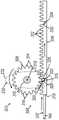
图6描绘了图1的导管组件的柄部和偏转驱动组件的透视图,其中偏转驱动组件包括摇臂;6 depicts a perspective view of the handle and yaw drive assembly of the catheter assembly of FIG. 1, wherein the yaw drive assembly includes a rocker arm;
图7描绘了图6的柄部和偏转驱动组件的示意透视图,其中省略了柄部的一部分以显示包括齿条和小齿轮组件(rack and pinion assembly)的内部部件;7 depicts a schematic perspective view of the handle and yaw drive assembly of FIG. 6 with a portion of the handle omitted to show internal components including the rack and pinion assembly;
图8A描绘了图6的偏转驱动组件的顶部示意图,其中摇臂及齿条和小齿轮组件的齿条处于用于双向偏转的中立位置,并且第一示例性锁定组件处于解锁构造;8A depicts a top schematic view of the yaw drive assembly of FIG. 6 with the rocker arm and rack of the rack and pinion assembly in a neutral position for bi-directional yaw and the first exemplary locking assembly in an unlocked configuration;
图8B描绘了图8A的偏转驱动组件的顶部示意图,但是摇臂处于第一位置,齿条处于第一纵向位置,并且锁定组件处于第一锁定构造;8B depicts a top schematic view of the yaw drive assembly of FIG. 8A, but with the rocker arm in a first position, the rack in a first longitudinal position, and the locking assembly in a first locked configuration;
图8C描绘了图8A的偏转驱动组件的顶部示意图,但是摇臂处于第二位置,齿条处于第二纵向位置,并且锁定组件处于第二锁定构造;8C depicts a top schematic view of the yaw drive assembly of FIG. 8A, but with the rocker arm in a second position, the rack in a second longitudinal position, and the locking assembly in a second locked configuration;
图9A描绘了图1的导管的远侧部分的顶部平面图,其中省略了外部护套的一部分以显示内部部件,其中导管的远侧部分处于与图8A的摇臂的中立位置相关联的中立位置;9A depicts a top plan view of the distal portion of the catheter of FIG. 1 with a portion of the outer sheath omitted to show the inner components with the distal portion of the catheter in a neutral position associated with the neutral position of the rocker arm of FIG. 8A ;
图9B描绘了图1的导管的远侧部分的顶部平面图,其中省略了外部护套的一部分以显示内部部件,其中导管的远侧部分处于与图8B的摇臂的第一位置相关联的第一偏转位置;9B depicts a top plan view of the distal portion of the catheter of FIG. 1 with a portion of the outer sheath omitted to show the inner components with the distal portion of the catheter in a first position associated with the first position of the rocker arm of FIG. 8B a deflection position;
图9C描绘了图1的导管的远侧部分的顶部平面图,其中省略了外部护套的一部分以显示内部部件,其中导管的远侧部分处于与图8C的摇臂的第二位置相关联的第二偏转位置;9C depicts a top plan view of the distal portion of the catheter of FIG. 1 with a portion of the outer sheath omitted to show the inner components with the distal portion of the catheter in a first position associated with the second position of the rocker arm of FIG. 8C two deflection positions;
图10A描绘了图6的偏转驱动组件的顶部示意图,其中摇臂及齿条和小齿轮组件的齿条处于用于单向偏转的中立位置,并且锁定组件处于第一锁定构造;10A depicts a top schematic view of the yaw drive assembly of FIG. 6 with the rocker arm and rack of the rack and pinion assembly in a neutral position for one-way yaw and the locking assembly in a first locked configuration;
图10B描绘了图10A的偏转驱动组件的顶部示意图,但是摇臂处于第一旋转位置,齿条处于第一纵向位置,并且锁定组件处于第二锁定构造;10B depicts a top schematic view of the yaw drive assembly of FIG. 10A, but with the rocker arm in a first rotational position, the rack in a first longitudinal position, and the locking assembly in a second locked configuration;
图11A描绘了图1的导管的远侧部分的顶部平面图,其中省略了外部护套的一部分以显示内部部件,其中导管的远侧部分处于与处于图10A的中立位置的摇臂相关联的非偏转位置;FIG. 11A depicts a top plan view of the distal portion of the catheter of FIG. 1 with a portion of the outer sheath omitted to show the inner components, with the distal portion of the catheter in a non-directional position associated with the rocker arm in the neutral position of FIG. 10A . deflection position;
图11B描绘了图1的导管的远侧部分的顶部平面图,其中省略了外部护套的一部分以显示内部部件,其中导管的远侧部分处于与图10B的摇臂的第一位置相关联的偏转位置;11B depicts a top plan view of the distal portion of the catheter of FIG. 1 with a portion of the outer sheath omitted to show the inner components with the distal portion of the catheter in a deflection associated with the first position of the rocker arm of FIG. 10B Location;
图12描绘了第二示例性偏转驱动组件的顶部示意图,其中第二示例性锁定组件处于解锁构造;12 depicts a top schematic view of the second exemplary deflection drive assembly with the second exemplary locking assembly in an unlocked configuration;
图13描绘了第二示例性导管组件以及具有以示意性形式示出的附加组件的第三示例性偏转驱动组件的透视图,该第二示例性导管组件类似于图1的导管组件并且包括第二示例性导管;13 depicts a perspective view of a second exemplary catheter assembly similar to the catheter assembly of FIG. 1 and including a third exemplary deflection drive assembly with additional components shown in schematic form two exemplary conduits;
图14描绘了图13的偏转驱动组件的透视图,该偏转驱动组件包括第三示例性齿条和小齿轮组件、推拉式缆线和第三示例性锁定组件;14 depicts a perspective view of the yaw drive assembly of FIG. 13 including a third exemplary rack and pinion assembly, a push-pull cable, and a third exemplary locking assembly;
图15A描绘了图14的偏转驱动组件的顶部示意图,其中线性滑动件处于第一纵向位置,齿条和小齿轮组件的齿条处于第一纵向位置,并且锁定组件处于解锁构造;15A depicts a top schematic view of the yaw drive assembly of FIG. 14 with the linear slide in a first longitudinal position, the rack of the rack and pinion assembly in the first longitudinal position, and the locking assembly in an unlocked configuration;
图15B描绘了图15A的偏转驱动组件的顶部示意图,但是线性滑动件处于第二纵向位置,齿条和小齿轮组件的齿条处于第二纵向位置,并且锁定组件处于第一锁定构造;15B depicts a top schematic view of the yaw drive assembly of FIG. 15A, but with the linear slide in a second longitudinal position, the rack of the rack and pinion assembly in the second longitudinal position, and the locking assembly in the first locked configuration;
图15C描绘了图15A的偏转驱动组件的顶部示意图,但是线性滑动件处于第三纵向位置,齿条和小齿轮组件处于第三纵向位置,并且锁定组件处于第二锁定构造;Figure 15C depicts a top schematic view of the yaw drive assembly of Figure 15A, but with the linear slide in a third longitudinal position, the rack and pinion assembly in a third longitudinal position, and the locking assembly in a second locked configuration;
图16A描绘了图13的导管的远侧部分的顶部平面图,其中省略了外部护套的一部分以显示内部部件,其中导管的远侧部分处于与图15A的线性滑动件的第一纵向位置相关联的非偏转位置;16A depicts a top plan view of the distal portion of the catheter of FIG. 13 with a portion of the outer sheath omitted to show the inner components with the distal portion of the catheter in a first longitudinal position associated with the linear slide of FIG. 15A the non-deflected position of ;
图16B描绘了图13的导管的远侧部分的顶部平面图,其中省略了外部护套的一部分以显示内部部件,其中导管的远侧部分处于与图15B的线性滑动件的第二纵向置相关联的第一偏转位置;16B depicts a top plan view of the distal portion of the catheter of FIG. 13 with a portion of the outer sheath omitted to show the inner components with the distal portion of the catheter in a second longitudinal position associated with the linear slide of FIG. 15B The first deflection position of ;
图16C描绘了图13的导管的远侧部分的顶部平面图,其中省略了外部护套的一部分以显示内部部件,其中导管的远侧部分处于与图15C的线性滑动件的第三纵向位置相关联的第二偏转位置;16C depicts a top plan view of the distal portion of the catheter of FIG. 13 with a portion of the outer sheath omitted to show the inner components with the distal portion of the catheter in a third longitudinal position associated with the linear slide of FIG. 15C the second deflection position;
图17描绘了第四示例性偏转驱动器的顶部示意图,其中第四示例性锁定组件处于锁定构造;并且17 depicts a top schematic view of a fourth exemplary yaw drive with the fourth exemplary locking assembly in a locked configuration; and
图18描绘了操作图1的导管组件的示例性方法的图解视图;18 depicts a diagrammatic view of an exemplary method of operating the catheter assembly of FIG. 1;
具体实施方式Detailed ways
本发明的某些示例的以下说明不应用于限定本发明的范围。附图(未必按比例绘制)描绘了所选择的实施方案,并不旨在限制本发明的范围。详细描述以举例的方式而非限制性方式示出本发明的原理。根据以举例的方式示出的以下说明,本发明的其他示例、特征、方面、实施方案和优点对于本领域的技术人员而言将是显而易见的,一种最佳方式被设想用于实施本发明。如将认识到,本发明能够具有其他不同或等价的方面,所有这些方面均不脱离本发明。因此,附图和说明应被视为实质上是例示性的而非限制性的。The following description of certain examples of the invention should not be used to limit the scope of the invention. The drawings, which are not necessarily to scale, depict selected embodiments and are not intended to limit the scope of the invention. The detailed description illustrates the principles of the invention by way of example and not limitation. Other examples, features, aspects, embodiments and advantages of the invention will be apparent to those skilled in the art from the following description, shown by way of example, and a best mode is contemplated for carrying out the invention . As will be realized, the invention is capable of other different or equivalent aspects, all without departing from the invention. Accordingly, the drawings and description are to be regarded as illustrative in nature and not restrictive.
本文所述的教导内容、表达、型式、示例等中的任何一者或多者可与本文所述的其他教导内容、表达、型式、示例等中的任何一者或多者相结合。因此下述教导内容、表达、型式、示例等不应被视为彼此分离。参考本文的教导内容,本文的教导内容可进行组合的各种合适方式对于本领域的技术人员而言将显而易见。此类修改和变型旨在包括在权利要求书的范围内。Any one or more of the teachings, expressions, patterns, examples, etc. described herein may be combined with any one or more of the other teachings, expressions, patterns, examples, etc. described herein. Accordingly, the following teachings, expressions, patterns, examples, etc. should not be considered separate from each other. Various suitable ways in which the teachings herein may be combined will be apparent to those skilled in the art in view of the teachings herein. Such modifications and variations are intended to be included within the scope of the claims.
如本文所用,针对任何数值或范围的术语“约”或“大约”指示允许部件或元件的集合实现如本文所述的其预期要达到的目的的合适的尺寸公差。更具体地,“约”或“大约”可指列举值的值±10%的范围,例如“约90%”可指81%至99%的值范围。另外,如本文所用,术语“患者”、“宿主”、“用户”和“受检者”是指任何人或动物受检者,并不旨在将系统或方法局限于人使用,但本主题发明在人类患者中的使用代表优选的实施方案。As used herein, the terms "about" or "approximately" with respect to any numerical value or range indicate a suitable dimensional tolerance that allows a component or collection of elements to achieve its intended purpose as described herein. More specifically, "about" or "approximately" can refer to a range of ±10% of the value of the recited value, eg, "about 90%" can refer to a range of 81% to 99% of the value. Additionally, as used herein, the terms "patient," "host," "user," and "subject" refer to any human or animal subject and are not intended to limit the system or method to human use, but the subject matter The use of the invention in human patients represents a preferred embodiment.
I.示例性消融导管系统的概述I. Overview of Exemplary Ablation Catheter Systems
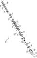
图1示出了可用于提供如上提及的心脏消融术的心脏消融导管系统的示例性医疗规程和相关联的部件。具体地,图1示出了医师(PH)抓握导管组件(100)的柄部(110),其中导管组件(100)的导管(120)的端部执行器(140)(在图2至图3中示出但未在图1中示出)设置在患者(PA)体内以消融患者(PA)的心脏(H)之中或附近的组织。如图2所示,导管组件(100)包括柄部(110)、从柄部(110)朝远侧延伸的导管(120)、位于导管(120)的远侧端部处的端部执行器(140)和与柄部(110)相关联的偏转驱动组件(200)。FIG. 1 illustrates an exemplary medical procedure and associated components of a cardiac ablation catheter system that may be used to provide a cardiac ablation procedure as mentioned above. Specifically, Figure 1 shows a physician (PH) grasping the handle (110) of the catheter assembly (100) with the end effector (140) of the catheter (120) of the catheter assembly (100) (in Figures 2 to 100). Shown in Figure 3 but not shown in Figure 1) is disposed in a patient (PA) to ablate tissue in or near the heart (H) of the patient (PA). As shown in Figure 2, the catheter assembly (100) includes a handle (110), a catheter (120) extending distally from the handle (110), an end effector located at the distal end of the catheter (120) (140) and a yaw drive assembly (200) associated with the handle (110).
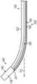
如将在下文更详细所述,端部执行器(140)包括各种部件,这些部件被构造成将RF能量递送到目标组织位点,提供EP标测功能,跟踪施加在端部执行器(140)上的外力,跟踪端部执行器(140)的位置以及分散冲洗流体。还如将在下文更详细所述,偏转驱动组件(200)被构造成使端部执行器(140)和导管(120)的远侧部分偏转远离由导管(120)的近侧部分限定的中心纵向轴线(L-L)(图3至图5)。As will be described in more detail below, the end effector (140) includes various components configured to deliver RF energy to a target tissue site, provide EP mapping functionality, track applications applied to the end effector (140) 140), tracking the position of the end effector (140) and dispersing the flushing fluid. Also as will be described in more detail below, the deflection drive assembly (200) is configured to deflect the end effector (140) and the distal portion of the catheter (120) away from a center defined by the proximal portion of the catheter (120). Longitudinal axis (L-L) (Figures 3 to 5).
如图3所示,导管(120)包括细长柔性护套(122),其中端部执行器(140)设置在外部护套(122)的远侧端部处。端部执行器(140)和容纳在外部护套(122)中的各种部件将在下文更详细地描述。导管组件(100)经由缆线(30)与引导和驱动系统(10)联接。导管组件(100)也经由流体管道(40)与流体源(42)联接。一组场发生器(20)定位在患者(PA)的下面,并且经由另一个缆线(22)与引导和驱动系统(10)联接。场发生器(20)仅是任选的。As shown in Figure 3, the catheter (120) includes an elongated flexible sheath (122) with an end effector (140) disposed at the distal end of the outer sheath (122). The end effector (140) and various components contained within the outer sheath (122) will be described in more detail below. A catheter assembly (100) is coupled to the guide and drive system (10) via a cable (30). Conduit assembly (100) is also coupled with fluid source (42) via fluid conduit (40). A set of field generators (20) is positioned below the patient (PA) and is coupled to the guidance and drive system (10) via another cable (22). The field generator (20) is optional only.
本示例的引导和驱动系统(10)包括控制台(12)和显示器(18)。控制台(12)包括第一驱动器模块(14)和第二驱动器模块(16)。第一驱动器模块(14)经由缆线(30)与导管组件(100)联接。在一些变型中,第一驱动器模块(14)可操作来接收经由端部执行器(140)的微电极(138)获得的EP标测信号,如在下文更详细地描述。控制台(12)包括处理器(未示出),该处理器处理此类EP标测信号,并且从而提供如本领域已知的EP标测。The boot and drive system (10) of this example includes a console (12) and a display (18). The console (12) includes a first driver module (14) and a second driver module (16). The first driver module (14) is coupled with the conduit assembly (100) via a cable (30). In some variations, the first driver module (14) is operable to receive EP mapping signals obtained via the microelectrodes (138) of the end effector (140), as described in more detail below. The console (12) includes a processor (not shown) that processes such EP mapping signals and thereby provides EP mapping as known in the art.
本示例的第一驱动器模块(14)还可操作以向端部执行器(140)的远侧末端构件(142)提供RF功率(如将在下文更详细地描述),从而消融组织。第二驱动器模块(16)经由缆线(22)与场发生器(20)联接。第二驱动器模块(16)可操作以激活场发生器(20),从而在患者(PA)的心脏(H)周围生成交变磁场。例如,场发生器(20)可包括在容纳心脏(H)的预先确定的工作体积中生成交变磁场的线圈。第一驱动器模块(14)还可操作来从端部执行器(140)中的导航传感器组件(150)接收位置指示信号。在此类型式中,控制台(12)的处理器还可操作来处理来自导航传感器组件(150)的位置指示信号,以由此确定端部执行器(140)在患者(PA)体内的位置。The first driver module (14) of this example is also operable to provide RF power (as will be described in more detail below) to the distal tip member (142) of the end effector (140), thereby ablating tissue. The second driver module (16) is coupled with the field generator (20) via a cable (22). The second driver module (16) is operable to activate the field generator (20) to generate an alternating magnetic field around the heart (H) of the patient (PA). For example, the field generator (20) may comprise a coil that generates an alternating magnetic field in a predetermined working volume containing the heart (H). The first driver module (14) is also operable to receive a position-indicating signal from a navigation sensor assembly (150) in the end effector (140). In this type of version, the processor of the console (12) is also operable to process position indication signals from the navigation sensor assembly (150) to thereby determine the position of the end effector (140) within the patient (PA) body .
导航传感器组件(150)包括位于相应面板(151)上的一对线圈,该对线圈可操作来生成指示端部执行器(140)在患者(PA)体内的位置和取向的信号。线圈被构造成响应于由场发生器(20)生成的交变电磁场的存在而生成电信号。可用于生成与端部执行器(140)相关联的实时位置数据的其他部件和技术可包括无线三角测量、声学跟踪、光学跟踪、惯性跟踪等。另选地,端部执行器(140)可不具有导航传感器组件(150)。The navigation sensor assembly (150) includes a pair of coils on respective panels (151) operable to generate signals indicative of the position and orientation of the end effector (140) within the patient (PA). The coil is configured to generate an electrical signal in response to the presence of an alternating electromagnetic field generated by the field generator (20). Other components and techniques that may be used to generate real-time position data associated with the end effector (140) may include wireless triangulation, acoustic tracking, optical tracking, inertial tracking, and the like. Alternatively, end effector (140) may not have navigation sensor assembly (150).
显示器(18)与控制台(12)的处理器联接,并且可操作以呈现患者解剖结构的图像。此类图像可基于一组手术前或手术中获得的图像(例如,CT或MRI扫描、3D标测图等)。通过显示器(18)提供的患者解剖结构的视图也可基于来自端部执行器(140)的导航传感器组件(150)的信号来动态地改变。例如,当导管(120)的端部执行器(140)在患者(PA)体内移动时,来自导航传感器组件(150)的对应位置数据可致使控制台(12)的处理器在显示器(18)中实时地更新患者解剖结构视图,以在端部执行器(140)在患者(PA)体内移动时描绘患者解剖结构在端部执行器(140)周围的区域。此外,控制台(12)的处理器可驱动显示器(18)以显示经由利用端部执行器(140)进行电生理(EP)标测检测到的或以其他方式(例如,使用专用EP标测导管等)检测到的异常导电组织位点的位置。仅以举例的方式,控制台(12)的处理器可驱动显示器(18)以诸如通过叠加被照明点、十字线或异常导电组织位点的一些其他形式的视觉指示,将异常导电组织位点的位置叠加在患者解剖结构的图像上。A display (18) is coupled to the processor of the console (12) and is operable to present images of the patient's anatomy. Such images may be based on a set of images obtained before or during surgery (eg, CT or MRI scans, 3D maps, etc.). The view of the patient's anatomy provided by the display (18) may also change dynamically based on signals from the navigation sensor assembly (150) of the end effector (140). For example, as the end effector (140) of the catheter (120) moves within the patient (PA), corresponding positional data from the navigation sensor assembly (150) may cause the processor of the console (12) to display the display (18) on the display (18). The patient anatomy view is updated in real-time in real-time to delineate the area of the patient's anatomy around the end effector (140) as the end effector (140) moves within the patient (PA). Additionally, the processor of the console (12) may drive the display (18) to display detected via electrophysiological (EP) mapping with the end effector (140) or otherwise (eg, using dedicated EP mapping) location of abnormally conductive tissue sites detected by catheters, etc. By way of example only, the processor of the console (12) may drive the display (18) to display an abnormally conductive tissue site such as by superimposing an illuminated dot, a crosshair, or some other form of visual indication of the abnormally conductive tissue site. The position of the anatomy is superimposed on the image of the patient's anatomy.
控制台(12)的处理器还可驱动显示器(18)以诸如通过叠加被照明点、十字线、端部执行器(140)的图形表示或一些其他形式的视觉指示而将端部执行器(140)的当前位置叠加在患者解剖结构的图像上。随着医师(PH)使端部执行器(140)在患者(PA)体内移动,这种叠加的视觉指示也可实时地在显示器(18)上的患者解剖结构的图像内移动,从而随着端部执行器(140)在患者(PA)体内移动而向操作者提供关于端部执行器(140)在患者(PA)体内的位置的实时视觉反馈。因此,通过显示器(18)提供的图像可有效地提供端部执行器(140)在患者(PA)体内的位置的视频跟踪,而不必具有观看端部执行器(140)的任何光学器械(即,相机)。在同一视图中,显示器(18)可同时在视觉上指示通过EP标测检测到的异常导电组织位点的位置。因此,医师(PH)可观看显示器(18)以观察端部执行器(140)相对于标测的异常导电组织位点以及相对于患者(PA)体内相邻解剖结构的图像的实时定位。The processor of the console (12) may also drive the display (18) to display the end effector (18) to the end effector (140), such as by overlaying illuminated dots, crosshairs, a graphical representation of the end effector (140), or some other form of visual indication. 140) is superimposed on the image of the patient's anatomy. As the physician (PH) moves the end effector (140) within the patient (PA), this superimposed visual indication may also move within the image of the patient's anatomy on the display (18) in real time, thereby following The end effector (140) moves within the patient (PA) to provide the operator with real-time visual feedback regarding the position of the end effector (140) within the patient (PA). Thus, the images provided by the display (18) can effectively provide video tracking of the position of the end effector (140) within the patient (PA) without having to have any optics to view the end effector (140) (ie ,camera). In the same view, the display (18) can simultaneously visually indicate the location of abnormally conductive tissue sites detected by EP mapping. Thus, the physician (PH) can view the display (18) to observe the real-time positioning of the end effector (140) relative to the mapped abnormally conductive tissue site and relative to the image of adjacent anatomical structures in the patient (PA).
本示例的流体源(42)包括包含盐水或一些其他合适的冲洗流体的袋。管道(40)包括柔性管,该柔性管进一步与泵(44)联接,可操作该泵以选择性地将流体从流体源(42)驱动至导管组件(100)。如在下文更详细地描述,此类冲洗流体可通过端部执行器(140)的远侧末端构件(142)的开口(158)排出。参考本文的教导内容,可以对本领域的技术人员而言将显而易见的任何合适方式提供这种冲洗。The fluid source (42) of this example includes a bag containing saline or some other suitable irrigation fluid. Conduit (40) includes flexible tubing further coupled to a pump (44) operable to selectively drive fluid from fluid source (42) to catheter assembly (100). As described in more detail below, such irrigation fluid may be expelled through opening (158) of distal tip member (142) of end effector (140). Such flushing may be provided in any suitable manner that will be apparent to those skilled in the art in view of the teachings herein.
II.导管组件的示例性端部执行器II. Exemplary End Effector for Catheter Assembly
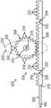
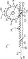
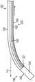
图3至图5更详细地示出了端部执行器(140)的示例性部件和导管(120)的远侧部分的其它部件。如上所述,端部执行器(140)包括各种部件,这些部件被构造成将RF能量递送到目标组织位点,提供EP标测功能,跟踪施加在端部执行器(140)上的外力,跟踪端部执行器(140)在患者(PA)体内的位置以及分散冲洗流体。例如,端部执行器(140)包括远侧末端构件(142)、远侧末端基座(144)、远侧电路盘(146)、应变仪组件(148)、导航传感器组件(150)、远侧间隔件叠堆(152)和一对近侧间隔件(154)。远侧末端构件(142)、远侧末端基座(144)、远侧电路盘(146)、应变仪组件(148)、导航传感器组件(150)、远侧间隔件叠堆(152)和近侧间隔件(154)彼此同轴对准并且纵向堆叠,使得这些部件(144-154)限定堆叠式电路。推拉式缆线(160)和冲洗管(180)可沿导管(120)的长度延伸以到达端部执行器(140)。将在下文更详细地描述前述部件中的每个部件。外部护套(122)围绕除了远侧末端构件(142)之外的所有前述部件,该外部护套可以是柔性的。3-5 illustrate exemplary components of end effector (140) and other components of the distal portion of catheter (120) in greater detail. As noted above, end effector (140) includes various components configured to deliver RF energy to a target tissue site, provide EP mapping functionality, and track external forces applied to end effector (140). , tracking the position of the end effector (140) within the patient (PA) and dispersing the irrigation fluid. For example, end effector (140) includes a distal tip member (142), a distal tip base (144), a distal circuit board (146), a strain gauge assembly (148), a navigation sensor assembly (150), a distal A stack of lateral spacers (152) and a pair of proximal spacers (154). Distal tip member (142), distal tip base (144), distal circuit board (146), strain gauge assembly (148), navigation sensor assembly (150), distal spacer stack (152) and proximal The side spacers (154) are coaxially aligned with each other and stacked longitudinally such that these components (144-154) define a stacked circuit. Push-pull cable (160) and irrigation tube (180) may extend along the length of catheter (120) to reach end effector (140). Each of the aforementioned components will be described in more detail below. An outer sheath (122), which may be flexible, surrounds all of the aforementioned components except for the distal tip member (142).
如图3至图5所示,本示例的远侧末端构件(142)包括具有穹顶末端的圆筒状主体(156)。圆筒状主体(156)和穹顶末端可以由导电材料(诸如金属)形成。多个开口(158)穿过圆筒状主体(156)形成并且与远侧末端构件(142)的中空内部连通。因此,开口(158)允许冲洗流体从远侧末端构件(142)的内部穿过圆筒状主体(156)传送出来。还可操作圆筒状主体(156)和穹顶末端以将RF电能施加到组织,从而消融组织。此类RF电能可经由缆线(30)从第一驱动器模块(14)传送到最近侧间隔件(154)。远侧末端构件(142)还可包括被构造成提供温度感测能力的一个或多个热电偶。As shown in Figures 3-5, the distal tip member (142) of this example includes a cylindrical body (156) having a domed tip. The cylindrical body (156) and dome tip may be formed of a conductive material such as metal. A plurality of openings (158) are formed through the cylindrical body (156) and communicate with the hollow interior of the distal tip member (142). Thus, opening (158) allows irrigation fluid to be delivered from the interior of distal tip member (142) through cylindrical body (156). The cylindrical body (156) and dome tip can also be manipulated to apply RF electrical energy to tissue, thereby ablating the tissue. Such RF power may be delivered from the first driver module (14) to the proximal-most spacer (154) via the cable (30). Distal tip member (142) may also include one or more thermocouples configured to provide temperature sensing capabilities.
如图3至图4所示,本示例的远侧末端构件(142)还包括安装到圆筒状主体(156)的一个或多个EP标测微电极(138)。EP标测微电极(138)被构造成从与EP标测微电极(138)形成接触的组织拾取电势。因此,EP标测微电极(138)可用于确定心血管解剖结构(例如,肺静脉等)内的组织中的异常电活动的位置。由EP标测微电极(138)拾取的信号可通过位于应变仪组件(148)近侧的层中的通孔或其他结构来传送,最终经由缆线(30)到达控制台(12)的第一驱动器模块(14)。根据本文引用的各种参考文献的教导内容,第一驱动器模块(14)可处理EP标测信号并向医师(PH)提供指示异常电活动的位置的对应反馈。As shown in Figures 3-4, the distal tip member (142) of this example also includes one or more EP mapping microelectrodes (138) mounted to the cylindrical body (156). The EP mapping microelectrode (138) is configured to pick up a potential from tissue in contact with the EP mapping microelectrode (138). Thus, EP mapping microelectrodes (138) can be used to locate abnormal electrical activity in tissue within cardiovascular anatomy (eg, pulmonary veins, etc.). The signals picked up by the EP mapping microelectrodes (138) may be transmitted through vias or other structures in the layers proximal to the strain gauge assembly (148), ultimately via the cable (30) to the first port of the console (12). A driver module (14). In accordance with the teachings of the various references cited herein, the first driver module (14) may process the EP mapping signal and provide corresponding feedback to the physician (PH) indicating the location of abnormal electrical activity.
在其中圆筒状主体(156)由导电材料形成以为组织消融提供RF电能的型式中,电绝缘材料可插置在圆筒状主体(156)和EP标测微电极(138)之间,从而将EP标测微电极(138)与圆筒状主体(156)电隔离。EP标测微电极(138)可根据本文引用的各种专利参考文献的教导内容来建造和操作。虽然仅示出了一个EP标测微电极(138),但是远侧末端构件(142)可包括两个或更多个EP标测微电极(138)。另选地,远侧末端构件(142)可完全不具有EP标测微电极(138)。远侧末端基座(144)限定中心孔,该中心孔被构造成提供用于将冲洗流体传送到远侧末端构件(142)的中空内部的路径。远侧末端基座144形成远侧末端构件(142)的近侧边缘可邻接的环形肩部。远侧末端构件(142)还限定横向凹口,该横向凹口被构造成接收远侧末端构件(142)的朝近侧延伸的突片。In versions where the cylindrical body (156) is formed of a conductive material to provide RF electrical energy for tissue ablation, an electrically insulating material may be interposed between the cylindrical body (156) and the EP mapping microelectrode (138), thereby The EP mapping microelectrode (138) is electrically isolated from the cylindrical body (156). The EP mapping microelectrode (138) can be constructed and operated in accordance with the teachings of the various patent references cited herein. Although only one EP mapping microelectrode (138) is shown, the distal tip member (142) may include two or more EP mapping microelectrodes (138). Alternatively, the distal tip member (142) may have no EP mapping microelectrode (138) at all. Distal tip base (144) defines a central bore configured to provide a pathway for delivering irrigation fluid to the hollow interior of distal tip member (142).
如图3至图4所示,远侧电路盘(146)定位在远侧末端基座(144)的近侧。远侧电路盘(146)包括可操作为经由远侧末端构件(142)的朝近侧延伸的突片将RF电能传送到远侧末端构件(142)的电路。在其中包括一个或多个EP标测电极(138)的型式中,远侧电路盘(146)还可包括能够操作来传送来自EP标测电极(138)的EP标测信号的电路。在一些型式中,远侧电路盘(146)还包括一个或多个发射线圈。此类发射线圈可提供信号(例如,来自微电极(138)的EP标测信号)到位于远侧电路盘(146)近侧的一个或多个互补线圈的无线通信。此外或另选地,此类发射线圈可提供RF电能从位于远侧电路盘(146)近侧的一个或多个互补线圈到远侧末端构件(142)的无线通信。As shown in Figures 3-4, the distal circuit tray (146) is positioned proximal of the distal tip base (144). Distal circuit tray (146) includes circuitry operable to deliver RF power to distal tip member (142) via proximally extending tabs of distal tip member (142). In versions in which one or more EP mapping electrodes (138) are included, the distal circuit board (146) may also include circuitry operable to transmit EP mapping signals from the EP mapping electrodes (138). In some versions, the distal circuit board (146) also includes one or more transmit coils. Such transmit coils may provide wireless communication of signals (eg, EP mapping signals from microelectrodes (138)) to one or more complementary coils located proximal to the distal circuit pad (146). Additionally or alternatively, such transmit coils may provide wireless communication of RF power from one or more complementary coils located proximal of the distal circuit board (146) to the distal tip member (142).
在其中线圈被并入到远侧电路盘(146)和位于应变仪组件(148)近侧的一个或多个其他层中的型式中,此类线圈可因此实现电信号跨应变仪组件(148)的无线通信,而不需要线、通孔或其他导电结构纵向穿过应变仪组件(148)。在一些型式中,远侧电路盘(146)包括与导航传感器组件(150)的接收线圈(RX)配对的至少一个发射线圈(TX),以检测施加到应变仪组件(148)的应变,以便确定施加到远侧末端(142)的接触力。远侧电路盘(146)的一些其他型式可简单地省略TX线圈。In versions in which the coils are incorporated into the distal circuit pad (146) and one or more other layers located proximal to the strain gauge assembly (148), such coils may thus enable electrical signals to cross the strain gauge assembly (148). ) without the need for wires, vias, or other conductive structures running longitudinally through the strain gauge assembly (148). In some versions, distal circuit board (146) includes at least one transmit coil (TX) paired with a receive coil (RX) of navigation sensor assembly (150) to detect strain applied to strain gauge assembly (148) in order to Determine the contact force applied to the distal tip (142). Some other versions of the distal circuit board (146) may simply omit the TX coil.
应变仪组件(148)定位在远侧电路盘(146)的近侧,并且被构造成感测撞击远侧末端构件(142)的外力。当远侧末端(142)遇到外力时(例如,当远侧末端(142)压靠着组织时),那些外力从远侧末端(142)传送到远侧末端基座(144)、传送到远侧电路盘(146)以及传送到应变仪组件(148),使得应变仪可生成对应于外力的量值和方向的合适信号。来自应变仪组件(148)的信号可通过位于应变仪组件(148)近侧的层中的通孔或其它结构来传送,最终经由缆线(30)到达控制台(12)的第一驱动器模块(14)。参考本文的教导内容,第一驱动器模块(14)可根据对本领域的普通技术人员而言将显而易见的任何合适方式处理应变信号。仅以举例的方式,当应变仪组件(148)指示远侧末端构件(142)遇到超过预先确定的阈值的力时,控制台(12)可提供听觉反馈以警示医师(PH),从而防止医师(PH)无意地用远侧末端构件(142)损坏心血管解剖结构。A strain gauge assembly (148) is positioned proximal of the distal circuit board (146) and is configured to sense external forces impinging on the distal tip member (142). When distal tip (142) encounters external forces (eg, when distal tip (142) is pressed against tissue), those external forces are transmitted from distal tip (142) to distal tip base (144), to Distal circuit board (146) and transmission to strain gauge assembly (148) so that the strain gauges can generate appropriate signals corresponding to the magnitude and direction of the external force. Signals from strain gauge assembly (148) may be routed through vias or other structures in layers proximal to strain gauge assembly (148), ultimately via cable (30) to the first driver module of console (12) (14). The first driver module (14) may process the strain signal in any suitable manner that will be apparent to one of ordinary skill in the art in view of the teachings herein. By way of example only, console (12) may provide audible feedback to alert the physician (PH) when strain gauge assembly (148) indicates that distal tip member (142) encounters a force that exceeds a predetermined threshold, thereby preventing The Physician (PH) inadvertently damaged the cardiovascular anatomy with the distal tip member (142).
导航传感器组件(150)可基本精确地生成指示端部执行器(140)在三维空间中的位置和取向的信号。导航传感器组件(150)包括多个面板(151),每个面板包括RX线圈,该RX线圈可操作为响应于由场发生器(20)生成的交变磁场而生成指示位置的电信号。每个RX线圈可由电迹线形成以限定电线圈或天线,从而接收由外部发射器TX线圈(例如,由定位在患者(PA)身体外部并发射离散射频的场发生器(20)提供的三个TX线圈)发射的射频信号,使得每个RX线圈的位置和取向可相对于由场发生器(20)提供的TX线圈来确定。来自导航传感器组件(150)的信号可通过位于应变导航传感器组件(150)近侧的层中的通孔或其它结构来传送,最终经由缆线(30)到达控制台(12)的第一驱动器模块(14)。The navigation sensor assembly (150) can generate substantially accurate signals indicative of the position and orientation of the end effector (140) in three-dimensional space. The navigation sensor assembly (150) includes a plurality of panels (151), each panel including an RX coil operable to generate an electrical signal indicative of a position in response to an alternating magnetic field generated by the field generator (20). Each RX coil may be formed of electrical traces to define an electrical coil or antenna to receive three signals provided by an external transmitter TX coil (eg, by a field generator (20) positioned outside the patient's (PA) body and emitting discrete radio frequencies) TX coils) so that the position and orientation of each RX coil can be determined relative to the TX coil provided by the field generator (20). Signals from the navigation sensor assembly (150) may be transmitted through vias or other structures in a layer proximal to the strain navigation sensor assembly (150), ultimately via the cable (30) to the first driver of the console (12) module (14).
导航传感器组件(150)的中心环形主体限定中心孔,该中心孔被构造成提供用于将冲洗流体传送到远侧末端构件(142)的中空内部的路径。在导航传感器组件的中心环形主体包括无线通信线圈的型式中,此类无线通信线圈还可与位于应变导航传感器组件(150)近侧的层中的通孔或其它结构联接,从而提供用于经由缆线(30)与控制台(12)的第一驱动器模块(14)电通信的路径。The central annular body of the navigation sensor assembly (150) defines a central bore configured to provide a path for delivering irrigation fluid to the hollow interior of the distal tip member (142). In versions where the central annular body of the navigation sensor assembly includes a wireless communication coil, such a wireless communication coil may also be coupled with a through hole or other structure in a layer proximal of the strain navigation sensor assembly (150), thereby providing access to via A path for the cable (30) in electrical communication with the first driver module (14) of the console (12).
在本示例中,每个远侧间隔件(153)大体成形为盘状,其中一对脊索切口彼此成角度地偏移90度。这些切口的大小和构造被设置成适应导航传感器组件(150)的相应面板(151),从而允许面板(151)径向地插置在远侧间隔件叠堆(152)和外部护套(122)之间。每个远侧间隔件(153)还包括至少一个缆线凹口,其中两个或更多个凹口可以彼此成角度地偏移180度。这种缆线凹口被构造成接收推拉式缆线(160)的远侧端部部分(164)。每个远侧间隔件(153)还包括中心孔,该中心孔被构造成提供用于将冲洗流体传送到远侧末端构件(142)的中空内部的路径。每个近侧间隔件(154)被成形为盘状,该盘具有二个或更多个穿过其中形成的孔。中心孔被构造成提供用于将冲洗流体传送到远侧末端构件(142)的中空内部的路径。侧孔的尺寸和构造被设置成接收推拉式缆线(160)的近侧部分(162)。还可以包括第二侧孔。In this example, each distal spacer (153) is generally shaped as a disk with a pair of notochord cuts angularly offset from each other by 90 degrees. These cutouts are sized and configured to accommodate the corresponding panels (151) of the navigation sensor assembly (150), thereby allowing the panels (151) to be inserted radially over the distal spacer stack (152) and outer sheath (122) )between. Each distal spacer (153) also includes at least one cable recess, wherein two or more recesses may be angularly offset from each other by 180 degrees. Such a cable recess is configured to receive a distal end portion (164) of a push-pull cable (160). Each distal spacer (153) also includes a central bore configured to provide a pathway for delivering irrigation fluid to the hollow interior of distal tip member (142). Each proximal spacer (154) is shaped as a disk having two or more holes formed therethrough. The central bore is configured to provide a pathway for delivering irrigation fluid to the hollow interior of distal tip member (142). The side holes are sized and configured to receive the proximal portion (162) of the push-pull cable (160). A second side aperture may also be included.
如上文所述并且如图1和图3所示,缆线(30)将导管组件(100)与驱动系统(10)联接。如图4所示,缆线(30)的线(32)沿导管(120)的长度延伸以到达最近侧的近侧间隔件(154)。因此,线(32)可容纳在外部护套(122)内。线(32)可以任何合适的方式与最近侧的近侧间隔件(154)物理联接和电联接。导管组件(100)被构造成使得冲洗流体能够经由流体管道(40)从流体源(42)传送到导管(120),从而提供冲洗流体经由远侧末端构件(142)的开口(158)的排出。在本示例中,用于冲洗流体的流体路径包括冲洗管(180),该冲洗管(180)在图4至图5中示出。冲洗管(180)的近侧端部与(例如,在导管组件(100)的柄部(110)处的)流体管道(40)联接。冲洗管(180)沿导管(120)的长度延伸以到达端部执行器(140)。在一些型式中,冲洗流体可从冲洗管(180)的远侧端部传送穿过中心通路,最终经由远侧末端基座(144)的孔(218)到达远侧末端构件(142)的内部。As described above and shown in Figures 1 and 3, a cable (30) couples the catheter assembly (100) with the drive system (10). As shown in Figure 4, the wire (32) of the cable (30) extends along the length of the catheter (120) to reach the proximal-most proximal septum (154). Thus, the wire (32) can be contained within the outer sheath (122). Wire (32) may be physically and electrically coupled to proximal-most proximal septum (154) in any suitable manner. Catheter assembly (100) is configured such that irrigation fluid can be delivered from fluid source (42) to catheter (120) via fluid conduit (40), thereby providing drainage of irrigation fluid through opening (158) of distal tip member (142) . In this example, the fluid path for the flushing fluid includes flushing tube (180), which is shown in Figures 4-5. The proximal end of the irrigation tube (180) is coupled with the fluid conduit (40) (eg, at the handle (110) of the catheter assembly (100)). Irrigation tube (180) extends along the length of catheter (120) to reach end effector (140). In some versions, irrigation fluid may be delivered from the distal end of irrigation tube (180) through the central passageway and ultimately to the interior of distal tip member (142) via bore (218) in distal tip base (144). .
如图5最佳所示,相应的远侧端部部分(164)具有比相应的中间部分(162)的外径更大的外径。远侧端部部分(174)与端部执行器(140)联接,以防止将推拉式缆线(160)朝近侧拉出端部执行器(140)。参考本文的教导内容,推拉式缆线(160)可与端部执行器(140)联接的合适方式对于本领域的技术人员而言将显而易见。As best shown in Figure 5, the respective distal end portions (164) have a larger outer diameter than the respective intermediate portions (162). The distal end portion (174) is coupled with the end effector (140) to prevent the push-pull cable (160) from being pulled proximally out of the end effector (140). Suitable ways in which push-pull cable (160) may be coupled with end effector (140) will be apparent to those skilled in the art in view of the teachings herein.
III.具有示例性偏转驱动组件的示例性导管组件III. Exemplary Catheter Assembly with Exemplary Deflection Drive Assembly
在一些情况下,多个生产线被用于建造导管。例如,第一生产线可以仅产生单向导管,并且第二生产线可以仅产生双向导管。单向导管是这样的导管,该导管仅沿单个方向(例如,向上、向下、向左或向右)偏转远离纵向轴线(L-L)。双向导管是这样的导管,其沿两个方向(例如,向上和向下或者向左和向右)偏转远离纵向轴线(L-L)。可以使用多个生产线,因为单向导管与双向导管之间存在几个结构差异,以实现这种偏转差异。这些差异可以包括柄部(110)和偏转机构(例如,偏转驱动组件)。In some cases, multiple production lines are used to build the conduit. For example, the first production line may produce only unidirectional conduits, and the second production line may produce bidirectional conduits only. A one-way catheter is a catheter that deflects away from the longitudinal axis (L-L) in only a single direction (eg, up, down, left, or right). A bidirectional catheter is a catheter that is deflected away from the longitudinal axis (L-L) in two directions (eg, up and down or left and right). Multiple production lines can be used because there are several structural differences between unidirectional and bidirectional catheters to achieve this deflection difference. These differences may include handle (110) and deflection mechanisms (eg, deflection drive assemblies).
为单向和双向导管使用一些相同的组件可能是有益的。这可能是有益的,因为然后可以使用同一个生产线来生产单向导管和双向导管两者。使用同一个生产线还可以节省训练组件操作员所需的时间,减少在生产线上混合部件的可能性,确保组件操作员在单向导管线和双向导管线之间的交叉兼容性,并在采购组件期间产生更大的批量折扣。It may be beneficial to use some of the same components for unidirectional and bidirectional catheters. This can be beneficial because the same production line can then be used to produce both unidirectional and bidirectional catheters. Using the same line also saves the time required to train component operators, reduces the likelihood of mixing parts on the line, ensures cross-compatibility for component operators between one-way and two-way lines, and during procurement of components Generate larger volume discounts.
为单向和双向导管使用相同或相似的柄部(110)也可以使医师(PH)更加安心,因为医师(PH)可能会对用户界面感到更加舒适。导管组件(100)捕获修改双向偏转机构以实现单向使用。相反,第二示例性导管组件(500)捕获修改双向偏转机构以实现单向使用。Using the same or similar handle (110) for unidirectional and bidirectional catheters may also provide greater peace of mind to the physician (PH), who may be more comfortable with the user interface. The catheter assembly (100) captures and modifies the bidirectional deflection mechanism for unidirectional use. In contrast, the second exemplary catheter assembly (500) captures and modifies the bidirectional deflection mechanism for unidirectional use.
如下文将更详细描述的,示例性偏转驱动组件(300,400,508,608)并入了示例性齿条和小齿轮组件(304,404,518,618),以(1)将来自摇臂(230,501)的小齿轮(308,408)的旋转运动传递到齿条(306,406)的线性运动中,或者(2)将来自线性滑动件(514,614)的齿条(524,624)的线性运动传递到小齿轮(526,626)的旋转运动中。如所示的,单个齿条(306,406,524,624)与小齿轮(308,408,526,626)相互作用。虽然输入构件在图2和图6至图12中被示出为摇臂(230,501),但该输入构件被示出和描述为图13至图17的导管组件(500,600)的线性滑动件(514,614)。鉴于本文的教导内容,其他合适的输入构件也被设想为对本领域技术人员显而易见的。As will be described in more detail below, the exemplary yaw drive assembly (300, 400, 508, 608) incorporates an exemplary rack and pinion assembly (304, 404, 518, 618) to (1) rotate the pinion (308, 408) from the rocker arm (230, 501) The motion is transferred to the linear motion of the racks (306, 406), or (2) the linear motion of the racks (524, 624) from the linear slides (514, 614) is transferred to the rotational motion of the pinions (526, 626). As shown, a single rack (306, 406, 524, 624) interacts with pinions (308, 408, 526, 626). While the input member is shown as a rocker arm (230, 501) in Figures 2 and 6-12, the input member is shown and described as a linear slide (514, 614) of the catheter assembly (500, 600) of Figures 13-17 ). Other suitable input means are also envisioned as would be apparent to those skilled in the art in view of the teachings herein.
A.用于双向端部执行器偏转的第一示例性导管组件A. First Exemplary Catheter Assembly for Bidirectional End Effector Deflection
图7示出了图6的柄部(110)和偏转驱动组件(300)的示意透视图,其中省略了柄部(110)的一部分以显示内部部件;如上所述,导管组件(100)包括柄部(110)、导管(120)、端部执行器(140)和偏转驱动组件(300)。导管(120)从柄部(110)朝远侧延伸。如图6所示,柄部(110)包括一起限定内部腔体(102)的第一壳体部分(112)和第二壳体部分(114)。摇臂(230)包括细长主体(232),用于增强医师(PH)的抓握。可旋转地致动双向导管的摇臂(230)的一个这样的合适示例在2019年6月25日提交的名称为“Catheter Deflection Systemwith Deflection Load Limiter”的美国临时专利申请号62/866,109中有示出和描述,该美国临时专利申请的公开内容以引用的方式全文并入本文。Figure 7 shows a schematic perspective view of the handle (110) and deflection drive assembly (300) of Figure 6, with a portion of the handle (110) omitted to show internal components; as described above, the catheter assembly (100) includes Handle (110), catheter (120), end effector (140) and deflection drive assembly (300). A catheter (120) extends distally from the handle (110). As shown in Figure 6, the handle (110) includes a first housing portion (112) and a second housing portion (114) that together define an interior cavity (102). The rocker arm (230) includes an elongated body (232) for enhancing the physician's (PH) grip. One such suitable example of a rocker arm (230) that rotatably actuates a bidirectional catheter is shown in US Provisional Patent Application No. 62/866,109, filed June 25, 2019, entitled "Catheter Deflection System with Deflection Load Limiter" Published and described, the disclosure of this US Provisional Patent Application is incorporated herein by reference in its entirety.
偏转驱动组件(300)被构造成使端部执行器(140)偏转远离由导管(120)的近侧部分限定的纵向轴线(L-L)。本示例的偏转驱动组件(300)包括与柄部(110)关联的摇臂(230)、平移组件(302)和与摇臂(230)联接的齿条和小齿轮组件(304)。平移组件(302)与齿条和小齿轮组件(304)和端部执行器(140)间接或直接联接。如所示的,平移组件(302)包括推拉式缆线(160)。如将在下文更详细所述,医师(PH)可相对于柄部(110)致动摇臂(230),使得齿条和小齿轮组件(304)致动推拉式缆线(160),以选择性地使端部执行器(140)横向偏转远离纵向轴线(L-L),从而使得医师(PH)能够主动地使端部执行器(140)在患者(PA)体内转向。摇臂(230)可以驱动平移组件(302)以使端部执行器(140)相对于纵向轴线(L-L)沿两个方向(向上和向下或者向左和向右)偏转一定角度(A)。摇臂(230)被构造成相对于柄部(110)围绕驱动轴线(D-D)旋转而不沿纵向轴线(L-L)平移。如所示的,驱动轴线(D-D)与纵向轴线(L-L)垂直。The deflection drive assembly (300) is configured to deflect the end effector (140) away from a longitudinal axis (L-L) defined by the proximal portion of the catheter (120). The yaw drive assembly (300) of the present example includes a rocker arm (230) associated with the handle (110), a translation assembly (302), and a rack and pinion assembly (304) coupled with the rocker arm (230). The translation assembly (302) is indirectly or directly coupled with the rack and pinion assembly (304) and the end effector (140). As shown, translation assembly (302) includes push-pull cable (160). As will be described in more detail below, the physician (PH) can actuate the rocker arm (230) relative to the handle (110) such that the rack and pinion assembly (304) actuates the push-pull cable (160) to select The end effector (140) is deflected laterally away from the longitudinal axis (L-L), thereby enabling the physician (PH) to actively steer the end effector (140) within the patient (PA). Rocker arm (230) can drive translation assembly (302) to deflect end effector (140) relative to longitudinal axis (L-L) by an angle (A) in both directions (up and down or left and right) . Rocker arm (230) is configured to rotate relative to handle (110) about drive axis (D-D) without translating along longitudinal axis (L-L). As shown, the drive axis (D-D) is perpendicular to the longitudinal axis (L-L).
齿条和小齿轮组件(304)具有齿条(306)和小齿轮(308)。在图7至图11B中仅示出了单个齿条(306)。齿条和小齿轮组件(304)将来自摇臂(230)的小齿轮(308)的旋转运动转换成齿条(306)的线性运动。齿条和小齿轮组件(304)使用轴(310)与摇臂(230)和平移组件(302)联接。如所示的,摇臂(230)和小齿轮(308)围绕驱动轴线(D-D)同轴。齿条(306)使用推拉式缆线(160)或驱动远侧末端构件(142)的单向偏转的另一个合适的平移构件可操作地与远侧末端构件(142)联接。齿条(306)包括多个齿(312)。类似地,小齿轮(308)包括被构造成选择性地啮合齿条(306)的齿(312)的多个齿(314)。如将参考图8A至图8C更详细描述的,偏转驱动组件(300)可以任选地包括锁定组件(316)。将描述几个合适的锁定组件示例;然而,也可以设想其他合适的锁定组件。The rack and pinion assembly (304) has a rack (306) and a pinion (308). Only a single rack (306) is shown in Figures 7-11B. Rack and pinion assembly (304) converts rotational motion of pinion (308) from rocker arm (230) into linear motion of rack (306). Rack and pinion assembly (304) is coupled with rocker arm (230) and translation assembly (302) using shaft (310). As shown, rocker arm (230) and pinion (308) are coaxial about drive axis (D-D). Rack (306) is operably coupled to distal tip member (142) using a push-pull cable (160) or another suitable translating member that drives unidirectional deflection of distal tip member (142). The rack (306) includes a plurality of teeth (312). Similarly, pinion (308) includes a plurality of teeth (314) configured to selectively engage teeth (312) of rack (306). As will be described in more detail with reference to Figures 8A-8C, the yaw drive assembly (300) may optionally include a locking assembly (316). Several examples of suitable locking assemblies will be described; however, other suitable locking assemblies are also contemplated.
如所示的,平移组件(302)具有与齿条(306)和端部执行器(140)联接的单个推拉式缆线(160)。特别地,推拉式缆线(160)使用多种合适的附接方法中的任一种附接方法在近侧附接点(318)处与齿条(306)联接。类似地,推拉式缆线(160)使用多种合适的附接方法中的任一种附接方法在远侧附接点(321)处与端部执行器(140)联接。虽然推拉式缆线(160)一般在齿条(306)与小齿轮(308)啮合之后与齿条(306)联接,但也可以设想推拉式缆线(160)可以在齿条(306)与小齿轮(308)啮合之前与齿条(306)联接。偏转驱动组件(300)传递齿条(306)的线性运动以沿远侧方向推动推拉式缆线(160)(参见图9B)或者沿近侧方向拉动推拉式缆线(160)(参见图9C)。特别地,齿条和小齿轮组件(304)被构造成使用来自摇臂(230)的输入沿相反方向驱动单个推拉式缆线(160)。虽然推拉式缆线(160)被示出为不锈钢杆,但也可以设想具有足够弯曲性和柱强度的其他合适的推拉式缆线。As shown, translation assembly (302) has a single push-pull cable (160) coupled to rack (306) and end effector (140). In particular, push-pull cable (160) is coupled with rack (306) at proximal attachment point (318) using any of a variety of suitable attachment methods. Similarly, push-pull cable (160) is coupled with end effector (140) at distal attachment point (321) using any of a variety of suitable attachment methods. While the push-pull cable (160) is typically coupled to the rack (306) after the rack (306) engages the pinion (308), it is also contemplated that the push-pull cable (160) may be coupled to the rack (306) with the rack (306). The pinion (308) is coupled with the rack (306) prior to meshing. Deflection drive assembly (300) transmits linear motion of rack (306) to push push-pull cable (160) in a distal direction (see Figure 9B) or pull push-pull cable (160) in a proximal direction (see Figure 9C) ). In particular, rack and pinion assembly (304) is configured to drive a single push-pull cable (160) in opposite directions using input from rocker arm (230). Although the push-pull cable (160) is shown as a stainless steel rod, other suitable push-pull cables with sufficient flexibility and column strength are also contemplated.
图8A至图8C示出了偏转驱动组件(300)使端部执行器(140)和导管(120)的远侧部分围绕纵向轴线(L-L)偏转的示例性使用。图8A和图9A示出了当端部执行器(140)处于中立的非偏转位置时的导管组件(100)。特别地,图8A示出了图6的偏转驱动组件(300)的顶部示意图,其中摇臂(230)处于中立位置。摇臂(230)能够绕枢轴点(319)枢转。当摇臂(230)处于中立位置时,齿条和小齿轮组件(304)的齿条(306)处于中立的非偏转位置。8A-8C illustrate exemplary use of the deflection drive assembly (300) to deflect the end effector (140) and the distal portion of the catheter (120) about the longitudinal axis (L-L). Figures 8A and 9A illustrate the catheter assembly (100) when the end effector (140) is in a neutral, non-deflected position. In particular, Figure 8A shows a top schematic view of the yaw drive assembly (300) of Figure 6 with the rocker arm (230) in a neutral position. The rocker arm (230) is pivotable about a pivot point (319). When the rocker arm (230) is in the neutral position, the rack (306) of the rack and pinion assembly (304) is in a neutral, non-deflected position.
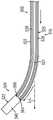
图9A示出了图1的导管(120)的远侧部分的顶部平面图,其中省略了外部护套(122)的一部分以显示内部部件。推拉式缆线(160)处于与处于中立的非偏转位置的端部执行器(140)相关联的中立的非偏转位置。如图9A至图9C所示,中间部分(162)从远侧端部部分(164)朝近侧延伸穿过导管(120)的外部护套(122)。中间部分(162)可包括彼此联接以便延伸至远侧端部部分(164)的各种节段。参考本文的教导内容,中间部分(162)的各种节段可通过对于本领域的技术人员而言将显而易见的任何合适方式来联接。Figure 9A shows a top plan view of the distal portion of the catheter (120) of Figure 1 with a portion of the outer sheath (122) omitted to show the internal components. The push-pull cable (160) is in a neutral, non-deflected position associated with the end effector (140) in a neutral, non-deflected position. As shown in Figures 9A-9C, intermediate portion (162) extends proximally through outer sheath (122) of catheter (120) from distal end portion (164). Intermediate portion (162) may include various segments coupled to each other so as to extend to distal end portion (164). The various segments of middle portion (162) may be coupled in any suitable manner that will be apparent to those skilled in the art in view of the teachings herein.
如图8A至图8C所示,锁定组件(316)插置于摇臂(230)和平移组件(302)之间。图8A示出了锁定组件(316),该锁定组件处于解锁构造从而使得端部执行器(140)可以沿一定范围的角度移动。在图8B和8C中示出的锁定构造中,锁定组件(316)将端部执行器(140)锁定在相对于纵向轴线(L-L)的期望角度。特别地,在图9B中,锁定组件(316)防止齿条(306)进一步朝远侧移动。锁定组件(316)包括限定锁定构造和解锁构造的锁定特征件(320,322,324)。如图8A所示,小齿轮(308)包括锁定特征件(320)。虽然小齿轮(308)被示出为仅包括单个锁定特征件(320),但小齿轮(308)可以包括围绕小齿轮(308)的圆周间隔开的两个或更多个锁定特征件。类似地,齿条(306)包括沿纵向轴线(L-L)彼此间隔开的锁定特征件(322,324)。如所示的,齿条(306)的锁定特征件(322,324)被设置在齿条(306)的工作长度的任一端部。齿条(306)可以包括更多或更少的锁定特征件。齿条(306)的锁定特征件(322,324)与小齿轮(308)的锁定特征件(320)互补。锁定特征件(320)在锁定构造中被构造成啮合锁定特征件(322,324)中的一个锁定特征件。As shown in Figures 8A-8C, the locking assembly (316) is interposed between the rocker arm (230) and the translation assembly (302). Figure 8A shows locking assembly (316) in an unlocked configuration allowing end effector (140) to move through a range of angles. In the locking configuration shown in Figures 8B and 8C, locking assembly (316) locks end effector (140) at a desired angle relative to longitudinal axis (L-L). In particular, in Figure 9B, locking assembly (316) prevents rack (306) from moving further distally. The locking assembly (316) includes locking features (320, 322, 324) that define a locked configuration and an unlocked configuration. As shown in Figure 8A, pinion (308) includes locking feature (320). Although pinion (308) is shown as including only a single locking feature (320), pinion (308) may include two or more locking features spaced around the circumference of pinion (308). Similarly, rack (306) includes locking features (322, 324) spaced apart from each other along longitudinal axis (L-L). As shown, the locking features (322, 324) of the rack (306) are provided at either end of the working length of the rack (306). Rack (306) may include more or fewer locking features. Locking features (322, 324) of rack (306) are complementary to locking feature (320) of pinion (308). The locking feature (320) is configured to engage one of the locking features (322, 324) in the locked configuration.
在解锁构造中,锁定特征件(322,324)与锁定特征件(320)间隔开一定距离。如所示的,锁定特征件(320,322,324)是圆筒状形状。特别地,小齿轮(308)的锁定特征件(320)是圆筒状销(326),而齿条(306)的锁定特征件(322,324)是圆筒状棘爪(328,330)。小齿轮(308)的锁定特征件(320)的圆筒状销(326)在锁定构造中被构造成可移除地与齿条(306)的锁定特征件(322,324)的圆筒状棘爪(328,330)联接(例如卡入到该圆筒状棘爪中)。圆筒状销(326)从摇臂(230)向下且整体地突出;与小齿轮(308)相邻。圆筒状销(326)可被定位成与齿轮齿尖相邻。圆筒状棘爪(328,330)可被形成到齿条(306)的齿轮齿槽中。In the unlocked configuration, locking features (322, 324) are spaced a distance from locking feature (320). As shown, the locking features (320, 322, 324) are cylindrical in shape. In particular, the locking feature (320) of the pinion (308) is a cylindrical pin (326) and the locking features (322, 324) of the rack (306) are cylindrical pawls (328, 330). The cylindrical pin (326) of the locking feature (320) of the pinion (308) is configured in the locking configuration to removably engage the cylindrical pawls of the locking features (322, 324) of the rack (306) (328, 330) coupled (eg snapped into the cylindrical pawl). Cylindrical pin (326) protrudes downwardly and integrally from rocker arm (230); adjacent pinion (308). Cylindrical pin (326) may be positioned adjacent to the gear tooth tips. Cylindrical pawls (328, 330) may be formed into the gear teeth of the rack (306).
使用摇臂(230)以相同或更少的量的阻力,可将小齿轮(308)的圆筒状销(326)从齿条(306)的圆筒状棘爪(328,330)中的一个圆筒状棘爪上移除,以解锁端部执行器(140)的偏转。圆筒状销(326)和圆筒状棘爪(328,330)提供了这样的联接,该联接足够强以抵抗当锁定组件(316)处于图10B或图10C所示的状态时齿条(306)的意外纵向运动(例如,响应于患者解剖结构等施加在端部执行器上的横向力的意外纵向运动);但足够弱以使操作员能够有意地使该组件在图10A至图10C中所示的状态之间转变,而无需在摇臂(230)上施加过度的扭矩。锁定组件(316)可以在进入或退出锁定构造或解锁构造时提供触觉指示。尽管未示出,但是还为锁定特征件(320,322,324)设想了多种非圆筒状形状,包括球形锁定特征件。Using the rocker arm (230) with the same or less amount of resistance, the cylindrical pin (326) of the pinion (308) can be moved from a circle in the cylindrical pawls (328, 330) of the rack (306) The barrel pawl is removed to unlock the deflection of the end effector (140). Cylindrical pin (326) and cylindrical pawls (328, 330) provide a coupling strong enough to resist rack (306) when locking assembly (316) is in the state shown in Figures 10B or 10C unintended longitudinal movement (e.g., in response to lateral forces exerted on the end effector by patient anatomy, etc.); but weak enough to allow the operator to intentionally cause the assembly to can transition between the states shown without applying undue torque on the rocker arm (230). The locking assembly (316) can provide a tactile indication when entering or exiting the locked or unlocked configuration. Although not shown, various non-cylindrical shapes are also contemplated for the locking features (320, 322, 324), including spherical locking features.
图8B示出了图8A的偏转驱动组件(300)的顶部示意图,但摇臂(230)处于第二位置(顺时针旋转180度),齿条(306)处于第一纵向位置,并且锁定组件(316)处于第一锁定构造。如图8B所示,第一锁定构造是齿条(306)的最远侧位置。图9B示出了图1的导管(120)的远侧部分的顶部平面图,其中省略了外部护套(122)的一部分以显示内部部件,其中导管(120)的远侧部分处于与图8B的摇臂(230)的第一位置相关联的第一偏转位置。如图9B中最佳所示,摇臂(230)向图8B中所示的旋转位置的旋转将齿条和小齿轮组件(304)驱动到对应的纵向位置,使得推拉式缆线(160)被朝朝远侧驱动。如图8B所示,在第一锁定构造中,锁定特征件(320)的圆筒状销(326)设置在锁定特征件(324)的圆筒状棘爪(330)中。Figure 8B shows a top schematic view of the yaw drive assembly (300) of Figure 8A, but with the rocker arm (230) in the second position (rotated 180 degrees clockwise), the rack (306) in the first longitudinal position, and the locking assembly (316) is in the first locked configuration. As shown in Figure 8B, the first locking configuration is the distal-most position of the rack (306). Figure 9B shows a top plan view of the distal portion of the catheter (120) of Figure 1 with a portion of the outer sheath (122) omitted to show the internal components, wherein the distal portion of the catheter (120) is in the same position as in Figure 8B A first deflected position associated with the first position of the rocker arm (230). As best shown in Figure 9B, rotation of the rocker arm (230) to the rotational position shown in Figure 8B drives the rack and pinion assembly (304) to the corresponding longitudinal position so that the push-pull cable (160) is driven distally. As shown in Figure 8B, in the first locking configuration, the cylindrical pin (326) of the locking feature (320) is disposed in the cylindrical pawl (330) of the locking feature (324).
当医师(PH)期望使端部执行器(140)相对于中心纵向轴线(L-L)偏转到图9C所示的偏转位置时,医师(PH)可使摇臂(230)相对于柄部(110)旋转到图8C所示的位置。特别地,图8C示出了图8A的偏转驱动组件(300)的顶部示意图,但摇臂(230)处于第二位置,齿条和小齿轮组件(304)处于第二纵向位置;并且锁定组件(316)处于第二锁定构造。如图8C所示,第二锁定构造是齿条(306)的最近侧位置。图9C示出了图1的导管(120)的远侧部分的顶部平面图,其中省略了外部护套(122)的一部分以显示内部部件,其中包括冲洗管(180)在内的导管(120)的远侧部分处于与摇臂(230)的第二位置相关联的偏转位置。如图8C所示,摇臂(230)向图8C中所示的旋转位置的旋转将齿条和小齿轮组件(304)的小齿轮(308)驱动到对应的旋转位置,使得齿条(306)和推拉式缆线(160)朝近侧移动。如图8C所示,在第二锁定构造中,锁定特征件(320)的圆筒状销(326)设置在锁定特征件(322)的圆筒状棘爪(328)中。设想了医师(PH)可以将用于移动端部执行器(140)的摇臂(230)从图8A所示的位置旋转到图8C所示的位置,而不需要将摇臂(230)旋转到图8B所示的位置。When the physician (PH) desires to deflect the end effector (140) relative to the central longitudinal axis (L-L) to the deflected position shown in FIG. ) to the position shown in Figure 8C. In particular, Figure 8C shows a top schematic view of the yaw drive assembly (300) of Figure 8A, but with the rocker arm (230) in the second position, the rack and pinion assembly (304) in the second longitudinal position; and the locking assembly (316) is in the second locked configuration. As shown in Figure 8C, the second locking configuration is the most proximal position of the rack (306). Figure 9C shows a top plan view of the distal portion of the catheter (120) of Figure 1 with a portion of the outer sheath (122) omitted to show the internal components, the catheter (120) including the irrigation tube (180) The distal portion of is in a deflected position associated with the second position of the rocker arm (230). As shown in Figure 8C, rotation of the rocker arm (230) to the rotational position shown in Figure 8C drives the pinion (308) of the rack and pinion assembly (304) to the corresponding rotational position such that the rack (306) ) and push-pull cable (160) move proximally. As shown in Figure 8C, in the second locking configuration, the cylindrical pin (326) of the locking feature (320) is disposed in the cylindrical pawl (328) of the locking feature (322). It is envisaged that the physician (PH) can rotate the rocker arm (230) used to move the end effector (140) from the position shown in FIG. 8A to the position shown in FIG. 8C without rotating the rocker arm (230) to the position shown in Figure 8B.
B.用于单向端部执行器偏转的第一示例性导管组件B. First Exemplary Catheter Assembly for Unidirectional End Effector Deflection
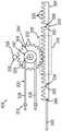
可能需要修改被构造成如图8A至图9C所示向端部执行器(140)提供双向偏转的偏转驱动组件(300),以替代地如图10A-11B所示向端部执行器(140)提供单向偏转。末端执行器(140)的这种从双向偏转到单向偏转的切换可以在偏转驱动组件(300)制造(例如组装)时通过修改偏转驱动组件(300)的中立位置实现。例如,如图10A至图11B所示,这可以通过修改齿条和小齿轮组件(304)的初始位置和平移组件(302)与齿条和小齿轮组件(304)联接的纵向位置来获得。It may be necessary to modify the deflection drive assembly (300), which is configured to provide bidirectional deflection to the end effector (140) as shown in Figures 8A-9C, to instead provide the end effector (140) to the end effector (140) as shown in Figures 10A-11B ) provides unidirectional deflection. This switching of end effector (140) from bidirectional to unidirectional deflection may be accomplished by modifying the neutral position of yaw drive assembly (300) during manufacture (eg, assembly) of yaw drive assembly (300). For example, as shown in Figures 10A-11B, this can be achieved by modifying the initial position of the rack and pinion assembly (304) and the longitudinal position of the translation assembly (302) coupled with the rack and pinion assembly (304).
图10A示出了图8A的偏转驱动组件(300)的顶部示意图,但摇臂(230)处于中立的非偏转位置,齿条(306)处于第一纵向位置,并且锁定组件(316)处于第一锁定构造。图11A示出了图1的导管(120)的远侧部分的顶部平面图,其中省略了外部护套(122)的一部分以显示内部部件,其中导管(120)的远侧部分处于中立的非偏转位置。如图10A所示,齿条和小齿轮组件(304)从图8A所示的中立构造调整为图10A所示的中立构造;并且推拉式缆线(160)被固定地紧固到齿条(306)上的纵向位置由图8A所示的中立位置调整为图10A所示的中立位置。如图10A所示,处于第一锁定构造的锁定组件(316)防止齿条(306)被朝远侧驱动。在第一锁定构造中,锁定特征件(320)的圆筒状销(326)设置在锁定特征件(324)的圆筒状棘爪(330)中。Figure 10A shows a top schematic view of the deflection drive assembly (300) of Figure 8A, but with the rocker arm (230) in the neutral, non-deflected position, the rack (306) in the first longitudinal position, and the locking assembly (316) in the first longitudinal position. A locking configuration. Figure 11A shows a top plan view of the distal portion of the catheter (120) of Figure 1 with a portion of the outer sheath (122) omitted to show the internal components with the distal portion of the catheter (120) in a neutral, non-deflected position Location. As shown in Figure 10A, the rack and pinion assembly (304) is adjusted from the neutral configuration shown in Figure 8A to the neutral configuration shown in Figure 10A; and the push-pull cable (160) is fixedly fastened to the rack ( 306) is adjusted from the neutral position shown in FIG. 8A to the neutral position shown in FIG. 10A . As shown in Figure 10A, the locking assembly (316) in the first locking configuration prevents the rack (306) from being driven distally. In the first locking configuration, the cylindrical pin (326) of the locking feature (320) is disposed in the cylindrical pawl (330) of the locking feature (324).
图10B示出了图10A的偏转驱动组件(300)的顶部示意图,但是摇臂(230)处于第一旋转位置,齿条(306)被移动到第一纵向位置,并且锁定组件(316)处于第二锁定构造。图11B示出了图1的导管(120)的远侧部分的顶部平面图,其中省略了外部护套(122)的一部分以显示内部部件,其中导管(120)的远侧部分处于与图10B的摇臂(230)的第一位置相关联的偏转位置。如图11B所示,摇臂(230)从图10A所示的位置向图10B所示的位置的旋转将齿条和小齿轮组件(304)驱动到相应的旋转位置,使得推拉式缆线(160)被朝近侧驱动。尽管在本附图中未必示出,但应当理解,导管(120)的远侧部分可利用图10A至图11B所示的布置实现的侧向偏转程度(即,弯曲角)比可利用图8A至图9C所示的布置实现的侧向偏转程度(即,弯曲角)大。Figure 10B shows a top schematic view of the yaw drive assembly (300) of Figure 10A, but with the rocker arm (230) in the first rotational position, the rack (306) moved to the first longitudinal position, and the locking assembly (316) in the first rotational position Second locking configuration. Figure 11B shows a top plan view of the distal portion of the catheter (120) of Figure 1 with a portion of the outer sheath (122) omitted to show the internal components, wherein the distal portion of the catheter (120) is in the same position as that of Figure 10B A deflection position associated with the first position of the rocker arm (230). As shown in Figure 11B, rotation of the rocker arm (230) from the position shown in Figure 10A to the position shown in Figure 10B drives the rack and pinion assembly (304) to the corresponding rotational position so that the push-pull cable ( 160) is driven proximally. Although not necessarily shown in this figure, it should be understood that the degree of lateral deflection (ie, bend angle) of the distal portion of catheter (120) that can be achieved using the arrangement shown in FIGS. 10A-11B is greater than that achievable using FIG. 8A . The degree of lateral deflection (ie, the bending angle) achieved by the arrangement shown in Figure 9C is large.
C.第二示例性锁定组件C. Second Exemplary Locking Assembly
图12示出了第二示例性偏转驱动组件(400)的顶部示意图,其中第二示例性锁定组件(416)处于解锁构造。偏转驱动组件(400)包括类似于摇臂(230)的摇臂(401)、类似于平移组件(302)的平移组件(402)和类似于齿条和小齿轮组件(304)的齿条和小齿轮组件(404)。齿条和小齿轮组件(404)包括齿条(406)和小齿轮(408)。齿条(406)包括齿(412),并且小齿轮(408)包括齿(414)。齿条(406)在与近侧附接点(318)类似的附接点(418)处与平移组件(402)的推拉式缆线(434)联接。锁定组件(416)包括位于小齿轮(408)上的锁定特征件(420)和位于齿条(406)上的锁定特征件(422,424)。例如,锁定特征件(422)被示出为圆筒状销(426),该圆筒状销从摇臂(230)向下且整体地突出;与小齿轮(408)相邻。圆筒状销(426)可被定位成与齿轮齿尖相邻。锁定特征件(422,424)是分别形成在齿轮齿槽中的圆筒状棘爪(428,430)。摇臂(401)可以使用轴(410)与小齿轮(408)联接。轴(410)可固定地联接到摇臂(401)和小齿轮(408)中额一者或两者上。Figure 12 shows a top schematic view of the second exemplary deflection drive assembly (400) with the second exemplary locking assembly (416) in an unlocked configuration. The yaw drive assembly (400) includes a rocker arm (401) similar to the rocker arm (230), a translation assembly (402) similar to the translation assembly (302), and a rack and pinion assembly (304). pinion assembly (404). The rack and pinion assembly (404) includes a rack (406) and a pinion (408). Rack (406) includes teeth (412) and pinion (408) includes teeth (414). Rack (406) is coupled with push-pull cable (434) of translation assembly (402) at attachment point (418) similar to proximal attachment point (318). Locking assembly (416) includes locking feature (420) on pinion (408) and locking features (422, 424) on rack (406). For example, locking feature (422) is shown as cylindrical pin (426) projecting downwardly and integrally from rocker arm (230); adjacent to pinion (408). Cylindrical pin (426) may be positioned adjacent to the gear tooth tips. The locking features (422, 424) are cylindrical pawls (428, 430) formed in the gear tooth slots, respectively. Rocker arm (401) may be coupled with pinion (408) using shaft (410). Shaft (410) may be fixedly coupled to one or both of rocker arm (401) and pinion (408).
锁定组件(416)可包括偏置构件(438),该偏置构件被构造成将齿条(406)偏置成远离小齿轮(408)以将锁定组件(416)从锁定构造转换为解锁构造。例如,齿条(406)可以由可弯曲材料(例如聚合物材料)形成。如所示的,偏置构件(438)从柄部(411)向外突出,使得偏置构件(438)可以由医师(PH)手动致动。设想了闭锁销(436)或偏置构件(438)可以单独使用或组合使用。Locking assembly (416) may include a biasing member (438) configured to bias rack (406) away from pinion (408) to convert locking assembly (416) from a locked configuration to an unlocked configuration . For example, rack (406) may be formed from a bendable material (eg, a polymeric material). As shown, biasing member (438) protrudes outwardly from handle (411) so that biasing member (438) can be manually actuated by a physician (PH). It is contemplated that the latching pin (436) or biasing member (438) may be used alone or in combination.
D.具有第三示例性锁定组件的用于双向端部执行器偏转的示例性导管组件的示D. Illustration of an Exemplary Catheter Assembly for Bidirectional End Effector Deflection with a Third Exemplary Locking Assembly例性导管组件Exemplary catheter assembly
包括可平移致动器(例如线性滑动件)的导管组件通常可以被构造成仅提供端部执行器(140)的单向偏转。可能需要生产这样的导管组件,该导管组件包括能够提供端部执行器(140)的双向偏转的线性滑动件。此外,可能需要使用同一个生产线来生产包括线性滑动件的单向导管和包括线性滑动件的双向导管。如前面所描述,为单向导管和双向导管使用同一个生产线还可以节省训练组件操作员所需的时间,减少在生产线上混合部件的可能性,确保组件操作员在单向导管生产线和双向导管生产线之间的交叉兼容性,并在采购组件期间产生更大的批量折扣。至少出于这些原因,第二示例性导管组件(500)包括能够向端部执行器(504)提供双向偏转的输入构件(示出为线性滑动件(514))。与单向偏转相比,双向偏转向端部执行器(504)提供了更大范围的偏转角。Catheter assemblies that include a translatable actuator (eg, a linear slide) can generally be configured to provide only one-way deflection of the end effector (140). It may be desirable to produce a catheter assembly that includes a linear slide capable of providing bidirectional deflection of the end effector (140). In addition, it may be desirable to use the same production line to produce unidirectional catheters including linear slides and bidirectional catheters including linear slides. As previously described, using the same line for both unidirectional and bidirectional catheters also saves the time required to train component operators, reduces the likelihood of mixing parts on the line, and ensures that component operators can work on both unidirectional and bidirectional catheter lines. Cross-compatibility between production lines and generate greater volume discounts during component procurement. For at least these reasons, the second exemplary catheter assembly (500) includes an input member (shown as a linear slide (514)) capable of providing bidirectional deflection to the end effector (504). Bi-directional deflection provides a greater range of deflection angles to the end effector (504) than unidirectional deflection.
图13示出了类似于图1的导管组件(100)的导管组件(500)的透视图,其中附加部件以示意性形式示出;导管组件(500)包括类似于导管(120)的第二示例性导管(502)、类似于端部执行器(140)的端部执行器(504)、类似于柄部(110)的柄部(506)和第三示例性偏转驱动组件(508)。柄部(506)包括第一壳体部分和第二壳体部分(510,512)。偏转驱动组件(508)包括线性滑动件(514)、平移组件(516)和齿条和小齿轮组件(518)。线性滑动件(514)能够由医师(PH)沿纵向轴线(L-L)在虚线所示的最远侧位置(DP)和也以虚线所示的最近侧位置(PP)之间以及在最远侧位置(DP)和最近侧位置(PP)之间的任何位置处滑动。如所示的,线性滑动件(514)沿纵向轴线(L-L)平移而不旋转。Figure 13 shows a perspective view of a conduit assembly (500) similar to conduit assembly (100) of Figure 1 with additional components shown in schematic form; conduit assembly (500) includes a second conduit similar to conduit (120) Exemplary catheter (502), end effector (504) similar to end effector (140), handle (506) similar to handle (110), and third exemplary deflection drive assembly (508). The handle (506) includes a first housing portion and a second housing portion (510, 512). The yaw drive assembly (508) includes a linear slide (514), a translation assembly (516), and a rack and pinion assembly (518). Linear slide (514) is capable of being used by the physician (PH) along the longitudinal axis (L-L) between a distal-most position (DP) shown in dashed line and a proximal-most position (PP) also shown in dashed line and at the most distal Swipe anywhere between the position (DP) and the closest side position (PP). As shown, the linear slide (514) translates along the longitudinal axis (L-L) without rotating.
平移组件(516)包括推拉式缆线(520)。推拉式缆线(520)和类似于冲洗管(180)的冲洗管(521)可沿导管(120)的长度延伸以到达端部执行器(504)。缆线(30)将导管组件(500)与上述驱动系统(10)联接起来。缆线(30)的类似于图3的线(32)的线沿导管(502)的长度延伸以到达最近侧的近侧间隔件。线(32)可包含在类似于外部护套(122)的外部护套(522)内。线(32)可以任何合适的方式与最近侧的近侧间隔件物理联接和电联接。Translation assembly (516) includes push-pull cable (520). A push-pull cable (520) and irrigation tube (521) similar to irrigation tube (180) may extend along the length of catheter (120) to reach end effector (504). A cable (30) couples the catheter assembly (500) with the drive system (10) described above. A wire of cable (30) similar to wire (32) of Figure 3 extends along the length of catheter (502) to reach the proximal-most proximal septum. The wire (32) may be contained within an outer sheath (522) similar to the outer sheath (122). Wire (32) may be physically and electrically coupled to the proximal-most proximal septum in any suitable manner.
导管组件(500)被构造成使得冲洗流体能够经由流体管道(40)从类似于图3的流体源(42)的流体源传送到导管(502),从而提供冲洗流体经由远侧末端构件(523)的类似于图3的开口(158)的开口排出。与远侧末端构件(142)类似,远侧末端构件(523)包括具有穹顶末端的圆筒状主体(540)(参见图16A至图16C)。在本示例中,用于冲洗流体的流体路径包括冲洗管(521)。冲洗管(521)的近侧端部与(例如,在导管组件(500)的柄部(506)处的)流体管道(40)联接。冲洗管(541)沿导管(502)的长度延伸以到达端部执行器(504)。在一些型式中,冲洗流体可从冲洗管(541)的远侧端部传送穿过中心通路,最终经由类似于孔(218)的孔到达远侧末端构件(523)的内部。Catheter assembly (500) is configured to enable irrigation fluid to be delivered to catheter (502) via fluid conduit (40) from a fluid source similar to fluid source (42) of Figure 3 to provide irrigation fluid via distal tip member (523) ) of an opening similar to opening (158) of FIG. 3 is discharged. Similar to distal tip member (142), distal tip member (523) includes a cylindrical body (540) with a domed tip (see Figures 16A-16C). In this example, the fluid path for flushing fluid includes flushing tube (521). The proximal end of irrigation tube (521) is coupled with fluid conduit (40) (eg, at handle (506) of catheter assembly (500)). Irrigation tube (541) extends along the length of catheter (502) to reach end effector (504). In some versions, irrigation fluid may be passed from the distal end of irrigation tube (541) through the central passageway, ultimately to the interior of distal tip member (523) via a hole similar to hole (218).
图14示出了图13的偏转驱动组件(508)的透视图。与齿条和小齿轮组件(304)类似的齿条和小齿轮组件(518)包括齿条(524)和小齿轮(526)。如所示的,线性滑动件(514)与齿条(524)可固定地联接。齿条和小齿轮组件(518)将从线性滑动件(514)的线性运动获得的齿条(524)的线性运动转换成小齿轮(526)的旋转运动。小齿轮(526)从轴(528)延伸。齿条(524)包括多个齿(530)。类似地,小齿轮(308)包括被构造成选择性地啮合齿条(524)的齿(530)的多个齿(532)。推拉式缆线(520)具有部分(536,538)。齿条(524)经由推拉式缆线(520)或驱动远侧末端构件(523)双向偏转的另一合适的平移构件连接到远侧末端构件(523)。FIG. 14 shows a perspective view of the yaw drive assembly ( 508 ) of FIG. 13 . Rack and pinion assembly (518), similar to rack and pinion assembly (304), includes rack (524) and pinion (526). As shown, linear slide (514) and rack (524) may be fixedly coupled. The rack and pinion assembly (518) converts the linear motion of the rack (524) obtained from the linear motion of the linear slide (514) into rotational motion of the pinion (526). Pinion (526) extends from shaft (528). The rack (524) includes a plurality of teeth (530). Similarly, pinion (308) includes a plurality of teeth (532) configured to selectively engage teeth (530) of rack (524). The push-pull cable (520) has sections (536, 538). Rack (524) is connected to distal tip member (523) via a push-pull cable (520) or another suitable translating member that drives bidirectional deflection of distal tip member (523).
继续参考图14,偏转驱动组件(508)包括与齿条和小齿轮组件(518)的小齿轮(526)同轴的滑轮(542)。滑轮(542)使用轴(528)可旋转地与小齿轮(526)联接。滑轮(542)包括界面表面(544),该界面表面被构造成摩擦地啮合推拉式缆线(520)。如将参考图15A至图16C更详细地描述的,柄部(110)使用齿条和小齿轮组件(518)将线性滑动件(514)的线性运动转换成通过滑轮(542)与推拉式缆线(520)同步的小齿轮(526)的旋转运动,以使远侧末端构件(523)偏转。远侧末端构件(523)沿多个方向偏转,同时在推拉式缆线(520)的部分(536,538)中的一个部分上提供张力并且在推拉式缆线(520)的部分(536,538)中的另一个部分上释放张力。With continued reference to Figure 14, the yaw drive assembly (508) includes a pulley (542) coaxial with the pinion (526) of the rack and pinion assembly (518). Pulley (542) is rotatably coupled with pinion (526) using shaft (528). Pulley (542) includes an interface surface (544) configured to frictionally engage push-pull cable (520). As will be described in more detail with reference to Figures 15A-16C, handle (110) uses a rack and pinion assembly (518) to convert linear motion of linear slide (514) into a connection between a pulley (542) and a push-pull cable Wire (520) synchronizes the rotational movement of pinion (526) to deflect distal tip member (523). The distal tip member (523) is deflected in multiple directions while providing tension on one of the portions (536, 538) of the push-pull cable (520) and on one of the portions (536, 538) of the push-pull cable (520) Release tension on the other section.
图15A至图16C示出了偏转驱动组件(508)使端部执行器(504)和导管(502)的远侧部分围绕中心纵向轴线(L-L)偏转的示例性使用。图15A示出了图14的偏转驱动组件(508)的顶部示意图。如所示的,线性滑动件(514)处于第一纵向位置(即中立位置),齿条和小齿轮组件(304)处于第一纵向位置(即中立位置),并且第三示例性锁定组件(534)处于解锁构造。虽然所示的中立位置具有设置在齿条(524)的中心中的小齿轮(526),但是该中立位置可以具有沿着齿条(524)朝更近侧或朝更远侧设置的小齿轮(526)。如图15A所示,小齿轮(526)和滑轮(542)彼此同轴并且彼此横向偏移。小齿轮(526)和滑轮(542)可经由轴(528)可旋转地联接在一起或者一起形成为一体件。例如,小齿轮(526)、轴(528)和滑轮(542)可以由塑料、金属或另外的合适的材料或材料组合形成。推拉式缆线(520)被示出为缠绕在滑轮(542)周围。齿条(524)的远侧部分可以在附接点(548)处与线(546)联接以使端部执行器(504)单向偏转,对于端部执行器(504)的单向偏转,通常不会省略该线。Figures 15A-16C illustrate exemplary use of the deflection drive assembly (508) to deflect the end effector (504) and the distal portion of the catheter (502) about the central longitudinal axis (L-L). FIG. 15A shows a top schematic view of the yaw drive assembly ( 508 ) of FIG. 14 . As shown, the linear slide (514) is in a first longitudinal position (ie, neutral), the rack and pinion assembly (304) is in a first longitudinal position (ie, neutral), and the third exemplary locking assembly ( 534) in the unlocked configuration. While the neutral position is shown with pinion (526) disposed in the center of rack (524), the neutral position may have pinions disposed more proximally or more distally along rack (524) (526). As shown in Figure 15A, pinion (526) and pulley (542) are coaxial with each other and laterally offset from each other. Pinion (526) and pulley (542) may be rotatably coupled together via shaft (528) or formed together as a single piece. For example, pinion (526), shaft (528), and pulley (542) may be formed from plastic, metal, or another suitable material or combination of materials. Push-pull cable (520) is shown wrapped around pulley (542). A distal portion of rack (524) may be coupled with wire (546) at attachment point (548) to allow one-way deflection of end effector (504), for one-way deflection of end effector (504) typically This line will not be omitted.
如图15A至图15C所示,偏转驱动组件(300)可以任选地包括类似于锁定组件(316)的锁定组件(534)。锁定组件(534)包括限定锁定构造和解锁构造的锁定特征件(552,554,556)。如图15A所示,小齿轮(526)包括锁定特征件(552)。虽然小齿轮(526)被示出为仅包括单个锁定特征件(552),但小齿轮(526)可以包括两个或更多个锁定特征件。类似地,齿条(524)包括沿纵向轴线(L-L)彼此间隔开的锁定特征件(554,556)。如所示的,齿条(524)的锁定特征件(554,556)被设置在齿条(524)的工作长度的任一端部。机架(524)可以包括更多或更少的锁定特征件。齿条(524)的锁定特征件(554,556)与小齿轮(526)的锁定特征件(552)互补。锁定特征件(552)在锁定构造中被构造成啮合锁定特征件(554,556)中的一个锁定特征件。As shown in Figures 15A-15C, the deflection drive assembly (300) may optionally include a locking assembly (534) similar to the locking assembly (316). The locking assembly (534) includes locking features (552, 554, 556) that define a locked configuration and an unlocked configuration. As shown in Figure 15A, pinion (526) includes locking feature (552). Although pinion (526) is shown as including only a single locking feature (552), pinion (526) may include two or more locking features. Similarly, rack (524) includes locking features (554, 556) spaced apart from each other along longitudinal axis (L-L). As shown, locking features (554, 556) of rack (524) are provided at either end of the working length of rack (524). Frame (524) may include more or fewer locking features. Locking features (554, 556) of rack (524) are complementary to locking feature (552) of pinion (526). The locking feature (552) is configured to engage one of the locking features (554, 556) in the locked configuration.
在解锁构造中,锁定特征件(554,556)与锁定特征件(552)间隔开一定距离。换言之,在图15A的解锁位置中,齿条(524)的锁定特征件(554,556)不与小齿轮(526)的锁定特征件(552)啮合。如所示的,锁定特征件(552,554,556)是圆筒状形状。特别地,小齿轮(526)的锁定特征件(552)是圆筒状销(558),而齿条(524)的锁定特征件(554,556)是圆筒状棘爪(560,562)。小齿轮(526)的锁定特征件(552)的圆筒状销(558)在锁定构造中被构造成可移除地与齿条(524)的锁定特征件(554,556)的圆筒状棘爪(560,562)联接(例如卡入到该圆筒状棘爪中)。圆筒状销(558)可被定位成与齿轮齿尖相邻。另选地,圆筒状销(558)可以从滑轮(542)整体突出;该滑轮可旋转地联接到小齿轮(526)。圆筒状棘爪(560,562)可被形成到齿条(524)的齿轮齿槽中。使用线性滑动件(514)以相同或更少的量的阻力,可将小齿轮(526)的圆筒状销(558)从齿条(524)的圆筒状棘爪(560,562)中的一个圆筒状棘爪上移除以解锁端部执行器(504)的偏转。因此,锁定组件(534)可以在进入或退出锁定构造和解锁构造时提供触觉指示。尽管未示出,但是还为锁定特征件(552,554,556)设想了多种非圆筒状形状。In the unlocked configuration, locking features (554, 556) are spaced a distance from locking feature (552). In other words, in the unlocked position of Figure 15A, the locking features (554, 556) of the rack (524) are not engaged with the locking feature (552) of the pinion (526). As shown, the locking features (552, 554, 556) are cylindrical in shape. In particular, the locking feature (552) of the pinion (526) is a cylindrical pin (558) and the locking features (554, 556) of the rack (524) are cylindrical pawls (560, 562). Cylindrical pin (558) of locking feature (552) of pinion (526) is configured to removably engage cylindrical pawls of locking features (554, 556) of rack (524) in a locked configuration (560, 562) coupled (eg, snapped into the cylindrical pawl). Cylindrical pin (558) may be positioned adjacent to the gear tooth tips. Alternatively, cylindrical pin (558) may protrude integrally from pulley (542); the pulley is rotatably coupled to pinion (526). Cylindrical pawls (560, 562) may be formed into gear teeth of rack (524). Using the linear slide (514) with the same or less amount of resistance, the cylindrical pin (558) of the pinion (526) can be moved from one of the cylindrical pawls (560, 562) of the rack (524) The cylindrical pawl is removed to unlock the deflection of the end effector (504). Accordingly, the locking assembly (534) can provide a tactile indication when entering or exiting the locked and unlocked configurations. Although not shown, various non-cylindrical shapes are also contemplated for the locking features (552, 554, 556).
图16A示出了图13的导管的远侧部分的顶部平面图,其中省略了外部护套(522)的一部分以显示内部部件,其中导管(502)的远侧部分处于与图15A的线性滑动件(514)的第一纵向位置相关联的中立的非偏转位置。因此,图16A示出了当端部执行器(504)处于中立的非偏转位置时的导管组件(500)。同样,推拉式缆线(520)处于与处于非偏转位置的端部执行器(504)相关联的第一位置。推拉式缆线(520)的部分(536)在附接点(564)处与端部执行器(504)的远侧末端构件(523)联接。类似地,推拉式缆线(520)的部分(538)在附接点(566)处与端部执行器(504)的远侧末端构件(523)联接。由于端部执行器(504)被示出为处于中立的非偏转位置,所以附接点(564)沿纵向轴线(L-L)设置在与附接点(566)大致相同的纵向位置处。Fig. 16A shows a top plan view of the distal portion of the catheter of Fig. 13 with a portion of the outer sheath (522) omitted to show the inner components, wherein the distal portion of the catheter (502) is in a linear slide relative to that of Fig. 15A (514) a neutral, non-deflected position associated with the first longitudinal position. Thus, Figure 16A shows catheter assembly (500) when end effector (504) is in a neutral, non-deflected position. Likewise, push-pull cable (520) is in a first position associated with end effector (504) in a non-deflected position. Portion (536) of push-pull cable (520) is coupled with distal tip member (523) of end effector (504) at attachment point (564). Similarly, portion (538) of push-pull cable (520) is coupled with distal tip member (523) of end effector (504) at attachment point (566). Since end effector ( 504 ) is shown in a neutral, non-deflected position, attachment point ( 564 ) is disposed at approximately the same longitudinal position along longitudinal axis (L-L) as attachment point ( 566 ).
图15B示出了图15A的偏转驱动组件(508)的顶部示意图。如所示的,线性滑动件(514)处于第二纵向位置,齿条和小齿轮组件(304)处于第二纵向位置,并且锁定组件(534)处于第一锁定构造。如图15B所示,线性滑动件(514)被朝远侧致动(由箭头(568)示出),该线性滑动件沿纵向轴线(L-L)朝远侧驱动齿条(524)。如图15B所示,第一锁定构造是齿条(524)的最近侧位置。由于齿条(524)的齿(530)与小齿轮(526)的齿(532)啮合,因此齿条(524)的纵向运动导致小齿轮(526)沿顺时针方向旋转(如箭头(570)所示)。小齿轮(526)的该顺时针旋转驱动滑轮(542)的顺时针旋转,因为小齿轮(526)和滑轮(542)可旋转地联接。例如,小齿轮(526)和滑轮(542)可以互为一体或者以其他方式整体地紧固在一起。滑轮(542)的顺时针旋转驱动推拉式缆线(520)的顺时针旋转。特别地,推拉式缆线(520)的部分(536)沿远侧方向(由箭头(572)所示)被推动并且推拉式缆线(520)的部分(538)沿近侧方向(由箭头(574)所示)被拉动。如图15B所示,在第一锁定构造中,锁定特征件(552)的圆筒状销(558)设置在锁定特征件(556)的圆筒状棘爪(562)中。Figure 15B shows a top schematic view of the yaw drive assembly (508) of Figure 15A. As shown, linear slide (514) is in a second longitudinal position, rack and pinion assembly (304) is in a second longitudinal position, and locking assembly (534) is in a first locking configuration. As shown in Figure 15B, linear slide (514) is actuated distally (shown by arrow (568)), which drives rack (524) distally along longitudinal axis (L-L). As shown in Figure 15B, the first locking configuration is the proximal-most position of the rack (524). Since teeth (530) of rack (524) mesh with teeth (532) of pinion (526), longitudinal movement of rack (524) causes pinion (526) to rotate in a clockwise direction (as indicated by arrow (570) shown). This clockwise rotation of pinion (526) drives clockwise rotation of pulley (542) because pinion (526) and pulley (542) are rotatably coupled. For example, pinion (526) and pulley (542) may be integral with each other or otherwise integrally fastened together. Clockwise rotation of pulley (542) drives clockwise rotation of push-pull cable (520). In particular, portion (536) of push-pull cable (520) is pushed in a distal direction (indicated by arrow (572)) and portion (538) of push-pull cable (520) is pushed in a proximal direction (indicated by arrow). (574)) is pulled. As shown in Figure 15B, in the first locking configuration, the cylindrical pin (558) of the locking feature (552) is disposed in the cylindrical pawl (562) of the locking feature (556).
另选地,还设想了滑轮(542)可以用链轮代替,并且推拉式缆线(520)的至少一部分(例如,在操作期间将直接啮合链轮的部分)可以用链条代替,使得该链条可以缠绕在该链轮周围,其中第一和第二推拉式缆线接合到该链条的每一个端部。在此种利用链条和链轮布置的替代布置中,第一和第二推拉式缆线沿纵向轴线(L-L)朝相反方向以类似于2019年6月25日提交的名称为“Catheter Deflection System with Deflection LoadLimiter”的美国临时专利申请号62/866,109中示出和描述的双向导管的方式移动,该美国临时专利申请的公开内容以引用的方式全文并入本文。Alternatively, it is also contemplated that pulley (542) may be replaced with a sprocket, and at least a portion of push-pull cable (520) (eg, the portion that would directly engage the sprocket during operation) may be replaced with a chain such that the chain It may be wrapped around the sprocket with the first and second push-pull cables joined to each end of the chain. In this alternative arrangement utilizing a chain and sprocket arrangement, the first and second push-pull cables are directed in opposite directions along the longitudinal axis (L-L) in a manner similar to the title "Catheter Deflection System with Deflection LoadLimiter" US Provisional Patent Application No. 62/866,109, the disclosure of which is incorporated herein by reference in its entirety.
图16B示出了图13的导管(502)的远侧部分的顶部平面图,其中省略了外部护套(522)的一部分以显示内部部件。如所示的,导管(502)的远侧部分处于与图15B的线性滑动件(514)的第二纵向位置相关联的第一偏转位置。当医师(PH)期望使端部执行器(504)相对于中心纵向轴线(L-L)沿第一方向偏转到图16B所示的第一偏转位置时,医师(PH)可使线性滑动件(514)相对于柄部(506)平移到图15B所示的位置。由于端部执行器(504)被示出为处于第一偏转位置,附接点(564)沿纵向轴线(L-L)设置在附接点(566)的远侧。Figure 16B shows a top plan view of the distal portion of catheter (502) of Figure 13 with a portion of outer sheath (522) omitted to show internal components. As shown, the distal portion of catheter (502) is in a first deflected position associated with the second longitudinal position of linear slide (514) of Figure 15B. When the physician (PH) desires to deflect the end effector (504) in a first direction relative to the central longitudinal axis (L-L) to the first deflected position shown in Figure 16B, the physician (PH) can cause the linear slide (514) ) is translated relative to the handle (506) to the position shown in Figure 15B. With end effector (504) shown in the first deflected position, attachment point (564) is disposed distal of attachment point (566) along longitudinal axis (L-L).
图15C描绘了图15A的偏转驱动组件(508)的顶部示意图,但是线性滑动件(514)处于第三纵向位置,齿条和小齿轮组件(518)处于第三纵向位置,并且锁定组件(534)处于第二锁定构造。如图15C所示,线性滑动件(514)被朝近侧致动(由箭头(576)示出),该线性滑动件沿纵向轴线(L-L)朝近侧驱动齿条(524)。由于齿条(524)的齿(530)与小齿轮(526)的齿(532)啮合,因此齿条(524)的纵向运动导致小齿轮(526)沿逆时针方向旋转(如箭头(578)所示)。小齿轮(526)的该旋转驱动滑轮(542)的逆时针旋转,因为小齿轮(526)和滑轮(542)可旋转地联接。滑轮(542)的逆时针旋转驱动推拉式缆线(160)的逆时针旋转。特别地,推拉式缆线(520)的部分(536)沿近侧方向(由箭头(580)所示)被拉动,并且推拉式缆线(520)的部分(538)沿远侧方向(如箭头(582)所示)被推动。如图15C所示,在第二锁定构造中,锁定特征件(552)的圆筒状销(558)设置在锁定特征件(554)的圆筒状棘爪(560)中。如图15C所示,第二锁定构造是齿条(524)的最近侧位置。Figure 15C depicts a top schematic view of the yaw drive assembly (508) of Figure 15A, but with the linear slide (514) in the third longitudinal position, the rack and pinion assembly (518) in the third longitudinal position, and the locking assembly (534) ) in the second locked configuration. As shown in Figure 15C, linear slide (514) is actuated proximally (shown by arrow (576)), which drives rack (524) proximally along longitudinal axis (L-L). Since teeth (530) of rack (524) mesh with teeth (532) of pinion (526), longitudinal movement of rack (524) causes pinion (526) to rotate in a counterclockwise direction (as indicated by arrow (578) shown). This rotation of pinion (526) drives counterclockwise rotation of pulley (542) because pinion (526) and pulley (542) are rotatably coupled. Counterclockwise rotation of pulley (542) drives counterclockwise rotation of push-pull cable (160). In particular, portion (536) of push-pull cable (520) is pulled in a proximal direction (indicated by arrow (580)), and portion (538) of push-pull cable (520) is pulled in a distal direction (as shown by arrow (580)) Arrow (582)) is pushed. As shown in Figure 15C, in the second locking configuration, the cylindrical pin (558) of the locking feature (552) is disposed in the cylindrical pawl (560) of the locking feature (554). As shown in Figure 15C, the second locking configuration is the most proximal position of the rack (524).
图16C示出了图13的导管(502)的远侧部分的顶部平面图,其中省略了外部护套的一部分以显示内部部件,其中导管(502)的远侧部分处于与图15C的线性滑动件(514)的第三纵向位置相关联的第二偏转位置。由于端部执行器(504)被示出为处于第二偏转位置,因此附接点(564)沿纵向轴线(L-L)设置在附接点(566)的近侧。Figure 16C shows a top plan view of the distal portion of the catheter (502) of Figure 13, with a portion of the outer sheath omitted to show the inner components, with the distal portion of the catheter (502) in a linear slide with the linear slide of Figure 15C (514) a second deflected position associated with the third longitudinal position. Since end effector (504) is shown in the second deflected position, attachment point (564) is positioned proximal of attachment point (566) along longitudinal axis (L-L).
E.第四示例性锁定组件E. Fourth Exemplary Locking Assembly
图17示出了第四示例性偏转驱动组件(608)的顶部示意图,其中第四示例性锁定组件(634)处于锁定构造。偏转驱动组件(608)包括类似于线性滑动件(514)的线性滑动件(614)、类似于平移组件(516)的平移组件(616)和类似于齿条和小齿轮组件(518)的齿条和小齿轮组件(618)。齿条和小齿轮组件(618)包括具有齿(630)的齿条(624)和具有齿(632)的小齿轮(626)。齿条(624)与线性滑动件(614)联接。锁定组件(634)包括位于小齿轮(626)上的锁定特征件(652)和位于齿条(624)上的锁定特征件(654,656)。例如,锁定特征件(652)被示出为圆筒状销(658),并且锁定特征件(654,656)是分别形成在齿轮齿槽中的圆筒状棘爪(660,662)。圆筒状销(658)可以与滑轮(642)一起形成。Figure 17 shows a top schematic view of the fourth exemplary deflection drive assembly (608) with the fourth exemplary locking assembly (634) in the locked configuration. Yaw drive assembly (608) includes linear slide (614) similar to linear slide (514), translation assembly (616) similar to translation assembly (516), and teeth similar to rack and pinion assembly (518) Bar and pinion assembly (618). The rack and pinion assembly (618) includes a rack (624) with teeth (630) and a pinion (626) with teeth (632). Rack (624) is coupled with linear slide (614). Locking assembly (634) includes locking feature (652) on pinion (626) and locking features (654, 656) on rack (624). For example, the locking feature (652) is shown as a cylindrical pin (658), and the locking features (654, 656) are cylindrical pawls (660, 662) formed in the gear tooth slots, respectively. Cylindrical pin (658) may be formed with pulley (642).
线性滑动件(614)被构造成沿纵向轴线(L-L)相对于柄部(606)平移。线性滑动件(614)使用轴(628)与小齿轮(626)联接。轴(628)将小齿轮(626)和滑轮(642)可旋转地联接起来。偏转驱动组件(608)包括与齿条和小齿轮组件(618)的小齿轮(626)同轴的滑轮(642)。滑轮(642)使用轴(628)与小齿轮(626)可旋转地联接。滑轮(642)包括被构造成接触推拉式缆线(620)的界面表面(644)。齿条(524)的远侧部分可以在附接点(548)处与线(546)联接。推拉式缆线(620)具有类似于推拉式缆线(520)的部分(636,638)。推拉式缆线(620)的部分(636)在类似于附接点(564)的附接点处与端部执行器(504)的远侧末端构件(523)联接。推拉式缆线(620)的部分(638)在类似于附接点(566)的附接点处与端部执行器(504)的远侧末端构件(523)联接。Linear slide (614) is configured to translate relative to handle (606) along longitudinal axis (L-L). Linear slide (614) is coupled with pinion (626) using shaft (628). Shaft (628) rotatably couples pinion (626) and pulley (642). The yaw drive assembly (608) includes a pulley (642) coaxial with the pinion (626) of the rack and pinion assembly (618). Pulley (642) is rotatably coupled with pinion (626) using shaft (628). Pulley (642) includes an interface surface (644) configured to contact push-pull cable (620). The distal portion of rack (524) may be coupled with wire (546) at attachment point (548). Push-pull cable (620) has portions (636, 638) similar to push-pull cable (520). Portion (636) of push-pull cable (620) is coupled with distal tip member (523) of end effector (504) at an attachment point similar to attachment point (564). Portion (638) of push-pull cable (620) is coupled with distal tip member (523) of end effector (504) at an attachment point similar to attachment point (566).
代替锁定特征件(652,654,656)或作为对锁定特征件(652,654,656)的补充,锁定组件(634)可包括这样的锁定特征件(示出为闭锁销(668)),该锁定特征件选择性地与线性滑动件(614)的齿(670)联接以保持端部执行器(504)的偏转角(参见图16A至图16C)。闭锁销(668)选择性地将线性滑动件(614)保持在锁定位置。代替锁定特征件(652,654,656)或闭锁销(668)或者作为对锁定特征件(652,654,656)或闭锁销(668)的补充,锁定组件(634)可包括这样的锁定特征件(示出为闭锁销(672)),该锁定特征件选择性地与齿条(624)的齿(674)联接以保持端部执行器(504)的偏转角(参见图16A-16C)。In place of or in addition to locking features (652, 654, 656), locking assembly (634) may include a locking feature (shown as locking pin (668)) that selectively interacts with Teeth (670) of linear slide (614) are coupled to maintain the deflection angle of end effector (504) (see Figures 16A-16C). Lockout pin (668) selectively retains linear slide (614) in the locked position. In place of or in addition to locking features (652, 654, 656) or latching pins (668), locking assembly (634) may include such locking features (shown as latching pins (652, 654, 656) or latching pins (668) 672)), the locking feature selectively couples with the teeth (674) of the rack (624) to maintain the deflection angle of the end effector (504) (see Figures 16A-16C).
F.示例性方法F. Exemplary Methods
图18示出了操作导管组件(100,500)的方法(700)。方法(700)的步骤(702a)包括使用旋转运动手动致动摇臂(230,401)。方法(700)的步骤(702b)包括使用线性运动手动致动线性滑动件(514,614)。方法(700)的步骤(704a)包括将摇臂(230,401)的旋转运动传递到小齿轮(308,408)。方法(700)的步骤(704b)包括将线性滑动件(514,614)的线性运动传递到齿条(524,624)。Figure 18 shows a method (700) of operating a catheter assembly (100, 500). Step (702a) of the method (700) includes manually actuating the rocker arms (230, 401) using a rotational motion. Step (702b) of the method (700) includes manually actuating the linear slide (514, 614) using a linear motion. Step (704a) of the method (700) includes transmitting the rotational motion of the rocker arm (230, 401) to the pinion (308, 408). Step (704b) of the method (700) includes transmitting the linear motion of the linear slide (514, 614) to the rack (524, 624).
方法(700)的步骤(706a)包括使用齿条和小齿轮组件(304,404)将小齿轮(308,408)的旋转运动转换成齿条(306,406)的后续旋转运动。方法(700)的步骤(706b)包括使用齿条和小齿轮组件(518,618)将齿条(524,624)的线性运动传递到小齿轮(526,626)的后续旋转运动中。方法(700)的步骤(708a)包括将齿条(306,406)的后续线性运动传递到平移组件(302,402)。方法(700)的步骤(708b)包括将小齿轮(526,626)的后续旋转运动传递到平移组件(516,616)。Step (706a) of the method (700) includes using the rack and pinion assembly (304, 404) to convert the rotational motion of the pinion (308, 408) to subsequent rotational motion of the rack (306, 406). Step (706b) of the method (700) includes using the rack and pinion assembly (518, 618) to transmit the linear motion of the rack (524, 624) into subsequent rotational motion of the pinion (526, 626). Step (708a) of method (700) includes transmitting subsequent linear motion of rack (306, 406) to translation assembly (302, 402). Step (708b) of method (700) includes transmitting subsequent rotational motion of pinion gears (526, 626) to translation assemblies (516, 616).
方法(700)的步骤(710)包括使用平移组件(302,402)使端部执行器(140)相对于纵向轴线(L-L)偏转一定角度或者使用平移组件(516,616)使偏转端部执行器(504)相对于纵向轴线(L-L)偏转一定角度。方法(700)的步骤(712)包括使用锁定组件(316,416,534,634)将端部执行器(140,504,604)锁定在远离纵向轴线(L-L)的期望角度处于锁定构造中。Step (710) of method (700) includes deflecting end effector (140) by an angle relative to longitudinal axis (L-L) using translation assemblies (302, 402) or deflecting end effector (504) using translation assemblies (516, 616) Deflected by an angle relative to the longitudinal axis (L-L). Step (712) of method (700) includes locking the end effector (140, 504, 604) in a locked configuration at a desired angle away from the longitudinal axis (L-L) using the locking assembly (316, 416, 534, 634).
IV.示例性组合IV. Exemplary Combinations
以下实施例涉及本文的教导内容可被组合或应用的各种非穷尽性方式。应当理解,以下实施例并非旨在限制可在本专利申请或本专利申请的后续提交文件中的任何时间提供的任何权利要求的覆盖范围。不旨在进行免责声明。提供以下实施例仅仅是出于例示性目的。预期本文的各种教导内容可按多种其他方式进行布置和应用。还设想到,一些变型可省略在以下实施例中所提及的某些特征。因此,下文提及的方面或特征中的任一者均不应被视为决定性的,除非另外例如由发明人或关注发明人的继承者在稍后日期明确指明如此。如果本专利申请或与本专利申请相关的后续提交文件中提出的任何权利要求包括下文提及的那些特征之外的附加特征,则这些附加特征不应被假定为因与专利性相关的任何原因而被添加。The following examples are directed to various non-exhaustive ways in which the teachings herein may be combined or applied. It should be understood that the following examples are not intended to limit the scope of coverage of any claims that may be presented at any time in this patent application or subsequent filings of this patent application. Not intended to make a disclaimer. The following examples are provided for illustrative purposes only. It is contemplated that the various teachings herein can be arranged and applied in a variety of other ways. It is also contemplated that some variations may omit certain features mentioned in the following embodiments. Accordingly, any of the aspects or features mentioned below should not be considered conclusive unless otherwise expressly indicated to do so at a later date, eg, by the inventor or a successor of the inventor concerned. If any claims presented in this patent application or in subsequent filings related to this patent application include additional features than those mentioned below, such additional features shall not be presumed for any reason related to patentability was added.
实施例1Example 1
一种设备,该设备包括:(a)柄部;(b)导管,该导管从该柄部朝远侧延伸,该导管的近侧部分限定纵向轴线;(c)端部执行器,该端部执行器从该导管朝远侧延伸,该端部执行器包括至少一个电极;(d)偏转驱动组件,该偏转驱动组件被构造成使端部执行器偏转远离纵向轴线,该偏转驱动组件包括:(i)输入构件,该输入构件与柄部相关联;(ii)平移组件,该平移组件联接到端部执行器;和(iii)齿条和小齿轮组件,该齿条和小齿轮组件与输入构件和平移组件联接,该齿条和小齿轮组件被构造成:(1)将来自输入构件的小齿轮的旋转运动传递到齿条的线性运动中,以朝远侧推动或者朝近侧拉动该平移构件,或(2)将来自输入构件的齿条的线性运动传递到小齿轮的旋转运动中,以使平移构件的第一端部朝近侧移动并且使平移构件的第二端部朝远侧移动。A device comprising: (a) a handle; (b) a catheter extending distally from the handle, a proximal portion of the catheter defining a longitudinal axis; (c) an end effector, the end extending distally from the catheter, the end effector including at least one electrode; (d) a deflection drive assembly configured to deflect the end effector away from the longitudinal axis, the deflection drive assembly including : (i) an input member associated with the handle; (ii) a translation assembly coupled to the end effector; and (iii) a rack and pinion assembly, the rack and pinion assembly Coupled with the input member and translation assembly, the rack and pinion assembly is configured to: (1) transmit rotational motion of the pinion from the input member into linear motion of the rack to push distally or proximally Pulling the translating member, or (2) transferring linear motion from the rack of the input member into rotational motion of the pinion to move the first end of the translating member proximally and the second end of the translating member Move distally.
实施例2Example 2
根据实施例1所述的设备,该输入构件包括摇臂,该摇臂被构造成相对于该柄部围绕驱动轴线旋转,该齿条和小齿轮组件被构造成将来自该摇臂的该小齿轮的旋转运动传递到该齿条的线性运动中,以朝远侧推动或朝近侧拉动该平移构件。According to the apparatus of
实施例3Example 3
根据实施例2所述的设备,该平移组件进一步包括与该齿条联接的推拉式缆线,该偏转驱动组件被构造成传递该齿条的线性运动,以沿远侧方向推动该推拉式缆线或者沿近侧方向拉动该推拉式缆线。The apparatus of embodiment 2, the translation assembly further comprising a push-pull cable coupled to the rack, the deflection drive assembly configured to transmit linear motion of the rack to urge the push-pull cable in a distal direction wire or pull the push-pull cable in a proximal direction.
实施例4Example 4
根据实施例2至实施例3中任何一项或多项所述的设备,该摇臂和该小齿轮围绕该驱动轴线同轴。According to the apparatus of any one or more of Embodiments 2 to 3, the rocker arm and the pinion are coaxial about the drive axis.
实施例5Example 5
根据实施例1所述的设备,该输入构件包括线性滑动件,该线性滑动件被构造成沿纵向轴线纵向移动,该齿条和小齿轮组件被构造成将来自该线性滑动件的该齿条的线性运动传递到该小齿轮的旋转运动中,以使平移构件的第一端部朝近侧移动并且使该平移构件的第二端部朝远侧移动。The apparatus of
实施例6Example 6
根据实施例1所述的设备,该平移组件进一步包括推拉式缆线,该推拉式缆线具有第一部分和第二部分,该偏转驱动组件被构造成传递该小齿轮的旋转运动,以沿远侧方向推动该推拉式缆线的该第一部分并且朝近侧方向拉动该推拉式缆线的该第二部分。The apparatus of
实施例7Example 7
根据实施例6所述的设备,该偏转驱动组件进一步包括滑轮,该滑轮与该齿条和小齿轮组件的小齿轮同轴,该滑轮包括被构造成与该推拉式缆线接触的界面表面。According to the apparatus of embodiment 6, the yaw drive assembly further includes a pulley coaxial with the pinion of the rack and pinion assembly, the pulley including an interface surface configured to contact the push-pull cable.
实施例8Example 8
根据实施例5至实施例7中的任何一项或多项所述的设备,该线性滑动件与该齿条可固定地联接,并且该滑轮与该小齿轮可旋转地联接。According to the apparatus of any one or more of Embodiments 5 to 7, the linear slide is fixedly coupled with the rack and the pulley is rotatably coupled with the pinion.
实施例9Example 9
根据任一前述实施例所述的设备,该设备进一步包括锁定组件,该锁定组件插置在该输入构件和该平移组件之间,该锁定组件能够在锁定构造和解锁构造之间移动,该锁定组件在锁定构造中被构造成将该端部执行器锁定在相对于纵向轴线的该角度。The apparatus of any preceding embodiment further comprising a locking assembly interposed between the input member and the translation assembly, the locking assembly movable between a locked configuration and an unlocked configuration, the locking The assembly is configured to lock the end effector at the angle relative to the longitudinal axis in the locked configuration.
实施例10Example 10
根据实施例9所述的设备,该锁定组件包括第一锁定特征件和第二锁定特征件,该第一锁定特征件和第二锁定特征件被构造成在锁定构造和解锁构造之间转变,该锁定组件在锁定构造中被构造成防止该平移组件沿着该纵向轴线平移。The device of embodiment 9, the locking assembly comprising a first locking feature and a second locking feature configured to transition between a locked configuration and an unlocked configuration, The locking assembly is configured to prevent translation of the translation assembly along the longitudinal axis in the locked configuration.
实施例11Example 11
根据实施例10所述的设备,该第一锁定特征件设置在该小齿轮上,该第二锁定特征件设置在该齿条上,该第二锁定特征件与该第一锁定特征件互补,该第一锁定特征件和第二锁定特征件在锁定构造中被构造成彼此啮合,该第一锁定特征件和第二锁定特征件在解锁构造中被构造成彼此间隔开一定距离。According to the apparatus of
实施例12Example 12
根据实施例10至实施例11中任一项或多项所述的设备,该第一锁定特征件和第二锁定特征件是圆筒状的。According to the apparatus of any one or more of
实施例13Example 13
根据实施例12所述的设备,该第一锁定特征件包括圆筒状销,该第二锁定特征件包括圆筒状棘爪,该棘爪在锁定构造中被构造成接收该圆筒状销。The apparatus of
实施例14Example 14
根据实施例13所述的设备,该圆筒状销从该输入构件上整体突出,该圆筒状棘爪被形成到该齿条的齿轮齿槽中。According to the apparatus of Embodiment 13, the cylindrical pin protrudes integrally from the input member, and the cylindrical pawl is formed into the gear tooth slot of the rack.
实施例15Example 15
根据实施例9至实施例14中任一项所述的设备,该锁定组件进一步包括偏置构件,该偏置构件被构造成将该齿条偏置成远离该小齿轮以切换到该解锁构造。The apparatus of any one of Embodiments 9 to 14, the locking assembly further comprising a biasing member configured to bias the rack away from the pinion to switch to the unlocked configuration .
实施例16Example 16
根据实施例1至实施例8中的任何一项或多项所述的设备,该设备进一步包括锁定组件,该锁定组件包括第一锁定特征件和第二锁定特征件,该第一锁定特征件和第二锁定特征件被构造成在锁定构造和解锁构造之间转变,该第一锁定特征件设置在平移组件上并且该第二锁定特征件选择性地定位在该柄部上。The apparatus of any one or more of
实施例17Example 17
根据实施例10所述的设备,该输入构件包括摇臂,该摇臂被构造成围绕驱动轴线相对于该柄部旋转,该第一锁定特征件设置在该摇臂上并且该第二锁定特征件能够在该柄部上移动。According to the apparatus of
实施例18Example 18
根据实施例17所述的设备,该驱动轴线与该纵向轴线垂直。According to the apparatus of
实施例19Example 19
根据实施例10所述的设备,该输入构件包括线性滑动件,该线性滑动件被构造成沿该纵向轴线相对于该柄部平移,该第一锁定特征件设置在该线性滑动件上并且该第二锁定特征件能够在该柄部上移动。The device of
实施例20Example 20
根据实施例1所述的设备,该平移组件由单个推拉式缆线组成,该齿条和小齿轮组件被构造成沿相反的方向驱动该单个推拉式缆线。According to the apparatus of Example 1, the translation assembly consists of a single push-pull cable, the rack and pinion assembly being configured to drive the single push-pull cable in opposite directions.
实施例21Example 21
根据实施例20所述的设备,该单个推拉式缆线包括不锈钢杆。According to the apparatus of
实施例22Example 22
根据实施例1至实施例21中任何一项或多项所述的设备,该至少一个电极被构造成发射RF能量。According to the apparatus of any one or more of
实施例23Example 23
根据实施例1至实施例22中任何一项或多项所述的设备,该至少一个电极被构造成执行电生理标测。According to the apparatus of any one or more of
实施例24Example 24
根据实施例1至实施例23中任何一项或多项所述的设备,该端部执行器包括应变仪组件。According to the apparatus of any one or more of
实施例25Example 25
根据实施例1至实施例24中任何一项或多项所述的设备,该端部执行器被构造成发射冲洗流体。According to the apparatus of any one or more of
实施例26Example 26
根据实施例1至实施例25中任何一项或多项所述的设备,该端部执行器包括位置传感器。According to the apparatus of any one or more of
实施例27Example 27
一种设备,该设备包括:(a)柄部;(b)导管,该导管从该柄部朝远侧延伸,该导管的近侧部分限定纵向轴线;(c)端部执行器,该端部执行器从该导管朝远侧延伸,该端部执行器包括至少一个电极;(d)偏转驱动组件,该偏转驱动组件被构造成使端部执行器偏转远离该纵向轴线,该偏转驱动组件包括:(i)与柄部相关联的输入构件,(ii)联接到端部执行器的平移组件,该输入构件被构造成驱动该平移组件以使该端部执行器偏转远离该纵向轴线一定角度,和(iii)与该输入构件和该平移组件联接的齿条和小齿轮组件,该齿条和小齿轮组件由齿条和小齿轮组成,该齿条和小齿轮组件被构造成:(1)将来自该输入构件的该小齿轮的旋转运动传递到该齿条的线性运动中,以朝远侧推动或者朝近侧拉动该平移构件,或(2)将来自输入构件的该齿条的线性运动传递到该小齿轮的旋转运动中,以使该平移构件的第一端部朝近侧移动并且使该平移构件的第二端部朝远侧移动;和(e)锁定组件,该锁定组件被构造成在锁定构造和解锁构造之间转变,该锁定组件包括第一锁定特征件和第二锁定特征件,该第一锁定特征件和第二锁定特征件在锁定构造中被构造成将该端部执行器锁定在远离该纵向轴线的该角度,该第一锁定特征件和第二锁定特征件在该解锁构造中被构造成允许该端部执行器沿着一定范围的角度移动。A device comprising: (a) a handle; (b) a catheter extending distally from the handle, a proximal portion of the catheter defining a longitudinal axis; (c) an end effector, the end extending distally from the catheter, the end effector including at least one electrode; (d) a deflection drive assembly configured to deflect the end effector away from the longitudinal axis, the deflection drive assembly Comprising: (i) an input member associated with the handle, (ii) a translation assembly coupled to the end effector, the input member configured to drive the translation assembly to deflect the end effector away from the longitudinal axis by a certain amount angle, and (iii) a rack and pinion assembly coupled with the input member and the translation assembly, the rack and pinion assembly consisting of a rack and pinion, the rack and pinion assembly being configured to: ( 1) transfer the rotational motion of the pinion from the input member into the linear motion of the rack to push distally or pull the translating member proximally, or (2) transfer the rack from the input member The linear motion of the pinion is transmitted into the rotational motion of the pinion to move the first end of the translating member proximally and the second end of the translating member distally; and (e) a locking assembly, the A locking assembly is configured to transition between a locked configuration and an unlocked configuration, the locking assembly including a first locking feature and a second locking feature, the first locking feature and the second locking feature being configured in the locked configuration to Locking the end effector at the angle away from the longitudinal axis, the first and second locking features in the unlocked configuration are configured to allow movement of the end effector along a range of angles.
实施例28Example 28
根据实施例27所述的设备,该锁定组件插置在该输入构件和该平移组件之间,该锁定组件在该锁定构造中被构造成防止该平移组件沿着该纵向轴线平移。According to the apparatus of embodiment 27, the locking assembly is interposed between the input member and the translating assembly, the locking assembly being configured in the locking configuration to prevent translation of the translating assembly along the longitudinal axis.
实施例29Example 29
根据实施例28所述的设备,该第一锁定特征件设置在该小齿轮上,该第二锁定特征件设置在该齿条上,该第二锁定特征件与该第一锁定特征件互补,该第一锁定特征件和第二锁定特征件在该锁定构造中被构造成彼此啮合,该第一锁定特征件和第二锁定特征件在该解锁构造中被构造成彼此间隔开一定距离。According to the apparatus of embodiment 28, the first locking feature is provided on the pinion, the second locking feature is provided on the rack, the second locking feature is complementary to the first locking feature, The first and second locking features are configured to engage with each other in the locked configuration, and the first and second locking features are configured to be spaced a distance from each other in the unlocked configuration.
实施例30Example 30
根据实施例27至实施例30中任一项或多项所述的设备,该第一锁定特征件和第二锁定特征件是圆筒状的。According to the apparatus of any one or more of Embodiments 27 to 30, the first and second locking features are cylindrical.
实施例31Example 31
根据实施例30所述的设备,该第一锁定特征件是圆筒状销,该第二锁定特征件是圆筒状棘爪,该圆筒状棘爪被构造成接收处于该锁定构造的圆筒状销。According to the apparatus of
实施例32Example 32
一种操作设备的方法,该设备包括:(a)柄部;(b)导管,该导管从该柄部朝远侧延伸,该导管的近侧部分限定纵向轴线;(c)端部执行器,该端部执行器从该导管朝远侧延伸,该端部执行器包括至少一个电极;(d)偏转驱动组件,该偏转驱动组件被构造成使该端部执行器偏转远离该纵向轴线,该偏转驱动组件包括:(i)输入构件,该输入构件与该柄部相关联,(ii)平移组件,该平移组件联接到该端部执行器;和(iii)齿条和小齿轮组件,该齿条和小齿轮组件与该输入构件和该平移组件联接,该齿条和小齿轮组件由齿条和小齿轮组成,该方法包括:(a)使用旋转运动或线性运动手动致动该输入构件;(b)将该输入构件的旋转运动传递给该小齿轮或者将该输入构件的线性运动传递给该齿条;(c)使用该齿条和小齿轮组件将该小齿轮的旋转运动传递到该齿条的后续线性运动中或者将该齿条的线性运动传递到该小齿轮的后续旋转运动中;(d)将该后续线性运动传递给该平移组件或者将该后续旋转运动传递给该平移组件;(e)使用该平移组件使该端部执行器偏离该纵向轴线一定角度。A method of operating a device comprising: (a) a handle; (b) a catheter extending distally from the handle, a proximal portion of the catheter defining a longitudinal axis; (c) an end effector , the end effector extending distally from the catheter, the end effector comprising at least one electrode; (d) a deflection drive assembly configured to deflect the end effector away from the longitudinal axis, The yaw drive assembly includes: (i) an input member associated with the handle, (ii) a translation assembly coupled to the end effector; and (iii) a rack and pinion assembly, The rack and pinion assembly is coupled with the input member and the translation assembly, the rack and pinion assembly is comprised of a rack and pinion, the method comprising: (a) manually actuating the input using either rotational or linear motion member; (b) transmit rotational motion of the input member to the pinion or linear motion of the input member to the rack; (c) transmit rotational motion of the pinion using the rack and pinion assembly into subsequent linear motion of the rack or into subsequent rotational motion of the pinion; (d) transferring the subsequent linear motion to the translation assembly or transferring the subsequent rotational motion to the a translation assembly; (e) using the translation assembly to angularly offset the end effector from the longitudinal axis.
实施例33Example 33
根据实施例32所述的方法,该方法进一步包括将该端部执行器锁定在远离该纵向轴线的角度处于该锁定构造中。The method of
实施例34Example 34
一种制造设备的方法,该设备包括:(a)柄部;(b)导管,该导管从该柄部朝远侧延伸,该导管的近侧部分限定纵向轴线;(c)端部执行器,该端部执行器从该导管朝远侧延伸,该端部执行器包括至少一个电极;和(d)偏转驱动组件,该偏转驱动组件被构造成使该端部执行器偏转远离该纵向轴线,该偏转驱动组件包括:(i)与柄部相关联的输入构件,(ii)联接到该端部执行器的平移组件,和(iii)与该输入构件和该平移组件联接的齿条和小齿轮组件,该齿条和小齿轮组件由齿条和小齿轮组成,该方法包括:(a)插入该小齿轮以使其与该齿条在被构造用于单向端部执行器偏转的第一位置处啮合,该第一位置与沿着该齿条的用于双向端部执行器偏转的第二位置纵向间隔开;或者插入该小齿轮以使其与该齿条在被构造用于双向端部执行器偏转的第三位置处啮合,该第三位置与沿着该齿条的用于单向端部执行器偏转的第四位置纵向间隔开;(b)将该平移组件与该齿条和小齿轮组件附接。A method of making a device comprising: (a) a handle; (b) a catheter extending distally from the handle, a proximal portion of the catheter defining a longitudinal axis; (c) an end effector , the end effector extending distally from the catheter, the end effector comprising at least one electrode; and (d) a deflection drive assembly configured to deflect the end effector away from the longitudinal axis , the yaw drive assembly includes: (i) an input member associated with the handle, (ii) a translation assembly coupled to the end effector, and (iii) a rack and a rack coupled to the input member and the translation assembly A pinion assembly, the rack and pinion assembly consisting of a rack and a pinion, the method comprising: (a) inserting the pinion to be in contact with the rack in a position configured for one-way end effector deflection meshing at a first position longitudinally spaced apart from a second position along the rack for bidirectional end effector deflection; or inserting the pinion so that it and the rack are configured for engaging at a third position for bidirectional end effector deflection longitudinally spaced apart from a fourth position along the rack for unidirectional end effector deflection; (b) connecting the translation assembly to the The rack and pinion assembly is attached.
V.杂项V. Miscellaneous
本文所述的器械中的任一个器械可在规程之前和/或之后进行清洁和消毒。在一种消毒技术中,将该装置放置在闭合且密封的容器诸如塑料袋或TYVEK袋中。然后可将容器和装置放置在可穿透容器的辐射场中,诸如γ辐射、x射线、或高能电子。辐射可杀死装置上和容器中的细菌。然后可将经消毒的装置储存在无菌容器中,以用于以后使用。也可使用本领域已知的任何其他技术对装置进行消毒,包括但不限于β或γ辐射、环氧乙烷、过氧化氢、过乙酸和气相消毒(具有或不具有气体等离子体或蒸汽)。Any of the instruments described herein can be cleaned and sterilized before and/or after the procedure. In one sterilization technique, the device is placed in a closed and sealed container such as a plastic bag or TYVEK bag. The container and device can then be placed in a radiation field that penetrates the container, such as gamma radiation, x-rays, or high-energy electrons. Radiation kills bacteria on devices and in containers. The sterilized device can then be stored in a sterile container for later use. The device may also be sterilized using any other technique known in the art, including but not limited to beta or gamma radiation, ethylene oxide, hydrogen peroxide, peracetic acid, and gas phase sterilization (with or without gas plasma or steam) .
应当理解,本文所述的任何实施例还可包括除上述那些之外或代替上述那些的各种其他特征。仅以举例的方式,本文所述的任何实施例还可包括以引用方式并入本文的各种参考文献中任何一者中公开的各种特征中的一种或多种。It should be understood that any of the embodiments described herein may also include various other features in addition to or in place of those described above. By way of example only, any embodiment described herein may also include one or more of the various features disclosed in any of the various references incorporated herein by reference.
应当理解,本文所述的教导内容、表达、实施方案、实施例等中的任何一者或多者可与本文所述的其他教导内容、表达、实施方案、实施例等中的任何一者或多者进行组合。因此,上述教导内容、表达、实施方案、实施例等不应被视为彼此孤立。参考本文的教导内容,本文的教导内容可进行组合的各种合适方式对于本领域的技术人员而言将显而易见。此类修改和变型旨在包括在权利要求书的范围内。It is to be understood that any one or more of the teachings, expressions, embodiments, examples, etc. described herein may be combined with any one or more of the other teachings, expressions, embodiments, examples, etc. described herein. Combine multiple. Accordingly, the above teachings, expressions, embodiments, examples, etc. should not be considered in isolation from each other. Various suitable ways in which the teachings herein may be combined will be apparent to those skilled in the art in view of the teachings herein. Such modifications and variations are intended to be included within the scope of the claims.
应当理解,据称以引用方式并入本文的任何专利、专利公布或其他公开材料,无论是全文或部分,仅在所并入的材料与本公开中所述的现有定义、陈述或者其他公开材料不冲突的范围内并入本文。因此,并且在必要的程度下,本文明确列出的公开内容代替以引用方式并入本文的任何冲突材料。据称以引用方式并入本文但与本文列出的现有定义、陈述或其他公开材料相冲突的任何材料或其部分,将仅在所并入的材料与现有的公开材料之间不产生冲突的程度下并入。It should be understood that any patent, patent publication or other published material, whether in whole or in part, said to be incorporated herein by reference is only intended to be consistent with existing definitions, representations or other disclosures set forth in this disclosure by the incorporated material. Materials are incorporated herein to the extent that they do not conflict. Accordingly, and to the extent necessary, the disclosure expressly set forth herein supersedes any conflicting material incorporated herein by reference. Any material, or portion thereof, purportedly incorporated herein by reference, but which conflicts with existing definitions, statements, or other disclosed material set forth herein, will not arise only between the incorporated material and the existing disclosed material merged to the extent of conflict.
在已经示出并描述了本发明的各种型式的情况下,通过本领域技术人员在不脱离本发明范围的前提下进行适当修改来实现对本文所述方法和系统的进一步改进。已经提及了若干此类可能的修改,并且其他修改对于本领域的技术人员而言将显而易见。例如,上文所讨论的实施例、型式、几何形状、材料、尺寸、比率、步骤等等均是示例性的而非必需的。因此,本发明的范围应根据以下权利要求书来考虑,并且应理解为不限于说明书和附图中示出和描述的结构和操作的细节。Having shown and described various versions of the invention, further improvements to the methods and systems described herein will be realized by those skilled in the art through appropriate modifications without departing from the scope of the invention. Several such possible modifications have been mentioned, and others will be apparent to those skilled in the art. For example, the embodiments, styles, geometries, materials, dimensions, ratios, steps, etc. discussed above are exemplary and not required. Accordingly, the scope of the invention should be considered in terms of the following claims and should not be understood to be limited to the details of construction and operation shown and described in the specification and drawings.
Claims (20)
Translated fromChineseApplications Claiming Priority (5)
| Application Number | Priority Date | Filing Date | Title |
|---|---|---|---|
| US201962948527P | 2019-12-16 | 2019-12-16 | |
| US62/948527 | 2019-12-16 | ||
| US17/089772 | 2020-11-05 | ||
| US17/089,772US20210177506A1 (en) | 2019-12-16 | 2020-11-05 | Catheter deflection control assembly |
| PCT/US2020/070885WO2021127686A1 (en) | 2019-12-16 | 2020-12-09 | Catheter deflection control assembly |
Publications (1)
| Publication Number | Publication Date |
|---|---|
| CN114828766Atrue CN114828766A (en) | 2022-07-29 |
Family
ID=76316614
Family Applications (1)
| Application Number | Title | Priority Date | Filing Date |
|---|---|---|---|
| CN202080087345.9APendingCN114828766A (en) | 2019-12-16 | 2020-12-09 | Catheter deflection control assembly |
Country Status (6)
| Country | Link |
|---|---|
| US (1) | US20210177506A1 (en) |
| EP (1) | EP4076241B1 (en) |
| JP (1) | JP7686646B2 (en) |
| CN (1) | CN114828766A (en) |
| IL (1) | IL293794A (en) |
| WO (1) | WO2021127686A1 (en) |
Families Citing this family (3)
| Publication number | Priority date | Publication date | Assignee | Title |
|---|---|---|---|---|
| DE102021119524B4 (en)* | 2021-07-28 | 2023-03-30 | Karl Storz Se & Co. Kg | Surgical instrument and steering gear therefor |
| US20240099768A1 (en)* | 2022-09-22 | 2024-03-28 | Biosense Webster (Israel) Ltd. | Two-segment deflectin catheter with side exit guidwire lumen |
| WO2025172839A1 (en)* | 2024-02-12 | 2025-08-21 | Magellan Biomedical Inc. | Mechanisms for operation of a cable-driven parallel manipulator |
Citations (8)
| Publication number | Priority date | Publication date | Assignee | Title |
|---|---|---|---|---|
| US20050096590A1 (en)* | 2003-10-30 | 2005-05-05 | Medtronic Inc. | Steerable catheter |
| US20050277874A1 (en)* | 2004-06-14 | 2005-12-15 | Selkee Thomas V | Steering mechanism for bi-directional catheter |
| US20070016164A1 (en)* | 2005-06-28 | 2007-01-18 | Dudney Joshua L | Actuation handle for a catheter |
| EP1803481A2 (en)* | 2005-12-30 | 2007-07-04 | Biosense Webster, Inc. | Dual-lever bi-directional handle |
| US20090112229A1 (en)* | 2007-10-31 | 2009-04-30 | Terumo Kabushiki Kaisha | Manipulator for medical use |
| CN101843509A (en)* | 2009-03-23 | 2010-09-29 | 伊西康内外科公司 | Circular surgical stapling instrument with anvil locking system |
| US20140324015A1 (en)* | 2013-04-30 | 2014-10-30 | Endosense Sa | Control handles for catheters |
| WO2017106235A1 (en)* | 2015-12-16 | 2017-06-22 | Ethicon Endo-Surgery, Llc | Surgical instrument with function selector |
Family Cites Families (16)
| Publication number | Priority date | Publication date | Assignee | Title |
|---|---|---|---|---|
| US4534339A (en)* | 1983-10-17 | 1985-08-13 | Warner-Lambert Technologies, Inc. | Endoscope |
| US5364351A (en)* | 1992-11-13 | 1994-11-15 | Ep Technologies, Inc. | Catheter steering mechanism |
| US8777929B2 (en)* | 2005-06-28 | 2014-07-15 | St. Jude Medical, Atrial Fibrillation Division, Inc. | Auto lock for catheter handle |
| EP1962665A4 (en) | 2005-12-20 | 2010-02-17 | Orthodynamix Llc | Method and devices for minimally invasive arthroscopic procedures |
| US9675369B2 (en)* | 2007-12-18 | 2017-06-13 | Boston Scientific Scimed, Inc. | Multi-functional medical device |
| US9016542B2 (en)* | 2010-09-30 | 2015-04-28 | Ethicon Endo-Surgery, Inc. | Staple cartridge comprising compressible distortion resistant components |
| US10743932B2 (en) | 2011-07-28 | 2020-08-18 | Biosense Webster (Israel) Ltd. | Integrated ablation system using catheter with multiple irrigation lumens |
| US9636481B2 (en)* | 2012-09-27 | 2017-05-02 | Boston Scientific Scimed, Inc. | Steerable catheter with brake assembly |
| US9451951B2 (en)* | 2012-11-07 | 2016-09-27 | Arthrex, Inc. | Suture snare with retractable sleeve |
| US9480416B2 (en) | 2014-01-17 | 2016-11-01 | Biosense Webster (Israel) Ltd. | Signal transmission using catheter braid wires |
| US9788893B2 (en) | 2014-11-20 | 2017-10-17 | Biosense Webster (Israel) Ltd. | Catheter with soft distal tip for mapping and ablating tubular region |
| US9801585B2 (en) | 2014-12-31 | 2017-10-31 | Biosense Webster (Israel) Ltd. | Electrocardiogram noise reduction |
| WO2017043128A1 (en)* | 2015-09-11 | 2017-03-16 | オリンパス株式会社 | Medical treatment instrument |
| US10660700B2 (en) | 2016-04-28 | 2020-05-26 | Biosense Webster (Israel) Ltd. | Irrigated balloon catheter with flexible circuit electrode assembly |
| US10702177B2 (en) | 2016-08-24 | 2020-07-07 | Biosense Webster (Israel) Ltd. | Catheter with bipole electrode spacer and related methods |
| US11376401B2 (en) | 2017-04-26 | 2022-07-05 | Acclarent, Inc. | Deflectable guide for medical instrument |
- 2020
- 2020-11-05USUS17/089,772patent/US20210177506A1/enactivePending
- 2020-12-09WOPCT/US2020/070885patent/WO2021127686A1/ennot_activeCeased
- 2020-12-09CNCN202080087345.9Apatent/CN114828766A/enactivePending
- 2020-12-09ILIL293794Apatent/IL293794A/enunknown
- 2020-12-09JPJP2022536784Apatent/JP7686646B2/enactiveActive
- 2020-12-09EPEP20829167.4Apatent/EP4076241B1/enactiveActive
Patent Citations (11)
| Publication number | Priority date | Publication date | Assignee | Title |
|---|---|---|---|---|
| US20050096590A1 (en)* | 2003-10-30 | 2005-05-05 | Medtronic Inc. | Steerable catheter |
| US20050277874A1 (en)* | 2004-06-14 | 2005-12-15 | Selkee Thomas V | Steering mechanism for bi-directional catheter |
| US20070016164A1 (en)* | 2005-06-28 | 2007-01-18 | Dudney Joshua L | Actuation handle for a catheter |
| EP1803481A2 (en)* | 2005-12-30 | 2007-07-04 | Biosense Webster, Inc. | Dual-lever bi-directional handle |
| US20070156116A1 (en)* | 2005-12-30 | 2007-07-05 | Gonzalez Pablo A | Dual-lever bi-directional handle |
| US20180078737A1 (en)* | 2005-12-30 | 2018-03-22 | Biosense Webster, Inc. | Dual-lever bi-directional handle |
| US20090112229A1 (en)* | 2007-10-31 | 2009-04-30 | Terumo Kabushiki Kaisha | Manipulator for medical use |
| CN101843509A (en)* | 2009-03-23 | 2010-09-29 | 伊西康内外科公司 | Circular surgical stapling instrument with anvil locking system |
| US20140324015A1 (en)* | 2013-04-30 | 2014-10-30 | Endosense Sa | Control handles for catheters |
| WO2017106235A1 (en)* | 2015-12-16 | 2017-06-22 | Ethicon Endo-Surgery, Llc | Surgical instrument with function selector |
| CN108366811A (en)* | 2015-12-16 | 2018-08-03 | 伊西康有限责任公司 | Surgical instruments with function selector |
Also Published As
| Publication number | Publication date |
|---|---|
| JP2023506506A (en) | 2023-02-16 |
| JP7686646B2 (en) | 2025-06-02 |
| WO2021127686A1 (en) | 2021-06-24 |
| EP4076241B1 (en) | 2025-10-08 |
| IL293794A (en) | 2022-08-01 |
| US20210177506A1 (en) | 2021-06-17 |
| EP4076241A1 (en) | 2022-10-26 |
Similar Documents
| Publication | Publication Date | Title |
|---|---|---|
| US12310715B2 (en) | Catheter deflection system with deflection load limiter | |
| EP4031007B1 (en) | Catheter instrument with three pull wires | |
| CN114340494A (en) | Mapping catheter with flexible panel electrode assembly | |
| EP4048178B1 (en) | Cardiac mapping catheter with square-spaced electrodes | |
| EP4076241B1 (en) | Catheter deflection control assembly | |
| JP7562660B2 (en) | CATHETER HAVING DEPOSITED FEATURES ON ITS TIP - Patent application | |
| CN114585317A (en) | Flare inserts for use with catheter assemblies | |
| JP7451524B2 (en) | Ablation catheter with laminated circuit assembly | |
| EP4360577A1 (en) | Irrigation tubing with regulated fluid emission | |
| EP4342405B1 (en) | Catheter shaft with multi-plane articulation and rotation | |
| US20230310071A1 (en) | Catheter with external magnetic coils | |
| CN117731914A (en) | Catheter shaft with multi-plane articulation and rotation | |
| CN117731915A (en) | Two-piece deflection catheter with side exit guidewire lumen | |
| CN116889465A (en) | Catheter with external magnetic coil |
Legal Events
| Date | Code | Title | Description |
|---|---|---|---|
| PB01 | Publication | ||
| PB01 | Publication | ||
| SE01 | Entry into force of request for substantive examination | ||
| SE01 | Entry into force of request for substantive examination |