CN114828355A - Light source uniformity adjusting method, system and device - Google Patents
Light source uniformity adjusting method, system and deviceDownload PDFInfo
- Publication number
- CN114828355A CN114828355ACN202110116919.7ACN202110116919ACN114828355ACN 114828355 ACN114828355 ACN 114828355ACN 202110116919 ACN202110116919 ACN 202110116919ACN 114828355 ACN114828355 ACN 114828355A
- Authority
- CN
- China
- Prior art keywords
- photosensitive sensor
- value
- light bar
- uniformity
- brightness
- Prior art date
- Legal status (The legal status is an assumption and is not a legal conclusion. Google has not performed a legal analysis and makes no representation as to the accuracy of the status listed.)
- Granted
Links
- 238000000034methodMethods0.000titleclaimsabstractdescription57
- 238000005259measurementMethods0.000claimsdescription14
- 230000035945sensitivityEffects0.000claimsdescription2
- 206010034972Photosensitivity reactionDiseases0.000description3
- 230000036211photosensitivityEffects0.000description3
- 238000012360testing methodMethods0.000description3
- 238000010586diagramMethods0.000description2
- 239000000523sampleSubstances0.000description2
- 238000003384imaging methodMethods0.000description1
- 239000000463materialSubstances0.000description1
- 238000012986modificationMethods0.000description1
- 230000004048modificationEffects0.000description1
- 238000006467substitution reactionMethods0.000description1
Images


Classifications
- H—ELECTRICITY
- H05—ELECTRIC TECHNIQUES NOT OTHERWISE PROVIDED FOR
- H05B—ELECTRIC HEATING; ELECTRIC LIGHT SOURCES NOT OTHERWISE PROVIDED FOR; CIRCUIT ARRANGEMENTS FOR ELECTRIC LIGHT SOURCES, IN GENERAL
- H05B47/00—Circuit arrangements for operating light sources in general, i.e. where the type of light source is not relevant
- H05B47/10—Controlling the light source
- H05B47/105—Controlling the light source in response to determined parameters
- H05B47/11—Controlling the light source in response to determined parameters by determining the brightness or colour temperature of ambient light
- Y—GENERAL TAGGING OF NEW TECHNOLOGICAL DEVELOPMENTS; GENERAL TAGGING OF CROSS-SECTIONAL TECHNOLOGIES SPANNING OVER SEVERAL SECTIONS OF THE IPC; TECHNICAL SUBJECTS COVERED BY FORMER USPC CROSS-REFERENCE ART COLLECTIONS [XRACs] AND DIGESTS
- Y02—TECHNOLOGIES OR APPLICATIONS FOR MITIGATION OR ADAPTATION AGAINST CLIMATE CHANGE
- Y02B—CLIMATE CHANGE MITIGATION TECHNOLOGIES RELATED TO BUILDINGS, e.g. HOUSING, HOUSE APPLIANCES OR RELATED END-USER APPLICATIONS
- Y02B20/00—Energy efficient lighting technologies, e.g. halogen lamps or gas discharge lamps
- Y02B20/40—Control techniques providing energy savings, e.g. smart controller or presence detection
Landscapes
- Light Sources And Details Of Projection-Printing Devices (AREA)
- Circuit Arrangement For Electric Light Sources In General (AREA)
Abstract
Description
Translated fromChinese技术领域technical field
本发明涉及机器视觉技术领域,具体涉及一种光源均匀性调节方法、系统以及装置。The invention relates to the technical field of machine vision, in particular to a method, system and device for adjusting the uniformity of a light source.
背景技术Background technique
在摄像头功能测试领域,摄像头测试设备中光环境控制尤为重要。光源的均匀性是摄像头测试设备的关键调节因素。各种光环境(包括红外光或白光等)都被要求较高的均匀性才能满足拍照过程摄像头采图的稳定性和成像质量。因此光源的均匀性成为设备供应商必须调节的设备指标。In the field of camera function testing, the control of light environment in camera test equipment is particularly important. The uniformity of the light source is a key adjustment factor for camera test equipment. Various light environments (including infrared light or white light, etc.) are required to have high uniformity in order to meet the stability and imaging quality of the camera during the photographing process. Therefore, the uniformity of the light source has become an equipment index that equipment suppliers must adjust.
目前光源均匀性调节的方法主要是人工手动或半自动测量光源亮度值,然后再记录不同点的亮度值,计算光源均匀性,再不断手动调整灯条亮度值,提高均匀性。该方法调节复杂,耗时长,特别是立体图卡环境,前置光源的光环境下,调节难度更大,效率更低,不利于量产出货。At present, the method of adjusting the uniformity of the light source is mainly to manually measure the brightness value of the light source manually or semi-automatically, then record the brightness value of different points, calculate the uniformity of the light source, and then manually adjust the brightness value of the light bar to improve the uniformity. This method is complicated to adjust and takes a long time, especially in a stereoscopic image card environment, and in the light environment of the front light source, the adjustment is more difficult and the efficiency is lower, which is not conducive to mass production and shipment.
发明内容SUMMARY OF THE INVENTION
本发明主要解决的技术问题是现有技术中光源均匀性调节效率低。The technical problem that the present invention mainly solves is the low efficiency of light source uniformity adjustment in the prior art.
一种光源均匀性调节方法,包括:A method for adjusting the uniformity of a light source, comprising:
分别计算标定板上每个感光传感器的亮度值与多个灯条控制的控制参数之间的斜率系数;Calculate the slope coefficient between the brightness value of each photosensitive sensor on the calibration board and the control parameters controlled by multiple light bars;
根据每个感光传感器对应的斜率系数、预设的每个感光传感器的目标亮度值构建每个感光传感器的亮度值线性约束方程;Construct a linear constraint equation of the brightness value of each photosensitive sensor according to the slope coefficient corresponding to each photosensitive sensor and the preset target brightness value of each photosensitive sensor;
根据每个感光传感器的亮度值线性约束方程以及预设的每个感光传感器的电流约束条件或者占空比约束条件,采用线性约束最小二乘法计算每个灯条的最优控制参数;According to the linear constraint equation of the brightness value of each photosensitive sensor and the preset current constraints or duty cycle constraints of each photosensitive sensor, the linear constrained least squares method is used to calculate the optimal control parameters of each light bar;
将设备上每个灯条的亮度控制参数设置为其对应的最优控制参数。Set the brightness control parameters of each light bar on the device to its corresponding optimal control parameters.
在一种实施例中,将设备上每个灯条的亮度控制参数设置为其对应的最优控制参数之后还包括:In an embodiment, after setting the brightness control parameter of each light bar on the device to its corresponding optimal control parameter, the method further includes:
计算所有感光传感器当前亮度值的均匀性值;Calculate the uniformity value of the current brightness value of all photosensitive sensors;
判断该均匀性值是否满足预设的均匀性阈值要求;Determine whether the uniformity value meets the preset uniformity threshold requirement;
若不满足,则对对应的灯条的控制参数进行微调;若满足,则停止对灯条的控制参数的调节。If not satisfied, fine-tune the control parameters of the corresponding light bar; if satisfied, stop adjusting the control parameters of the light bar.
在一种实施例中,灯条的控制参数为占空比或者电流值;In one embodiment, the control parameter of the light bar is a duty cycle or a current value;
所述分别计算标定板上每个感光传感器的亮度值与多个灯条控制的控制参数之间的斜率系数包括:The calculation of the slope coefficient between the brightness value of each photosensitive sensor on the calibration board and the control parameters controlled by the plurality of light bars includes:
对于任意一个感光传感器i,依次打开所有灯条,其中打开每个灯条时将该灯条的占空比或者电流值按最小到最大划分N等分点控制,在对应等分点下记录每个感光传感器值,基于N个等分点组成的电流值区间或者占空比区间以及对应的感光传感器的亮度值,采用线性最小二乘法计算出每个灯条的电流值或占空比与亮度值的子斜率系数,其中,所有灯条与一个感光传感器i之间的多个子斜率系数组成该感光传感器i对应的斜率系数;其中N≥2。For any photosensitive sensor i, turn on all the light bars in turn. When each light bar is turned on, the duty cycle or current value of the light bar is divided into N equal points from the smallest to the largest, and the corresponding equal points are recorded. Based on the current value interval or duty cycle interval composed of N equal points and the brightness value of the corresponding photosensitive sensor, the linear least squares method is used to calculate the current value or duty cycle and brightness of each light bar. The sub-slope coefficient of the value, wherein a plurality of sub-slope coefficients between all light bars and a photosensitive sensor i constitute the corresponding gradient coefficient of the photosensitive sensor i; wherein N≥2.
在一种实施例中,所述根据每个感光传感器对应的斜率系数、预设的每个感光传感器的目标亮度值构建每个感光传感器的亮度值线性约束方程包括:In an embodiment, the constructing a linear constraint equation of the brightness value of each photosensitive sensor according to the slope coefficient corresponding to each photosensitive sensor and the preset target brightness value of each photosensitive sensor includes:
对于任意一个感光传感器通过以下公式计算其亮度值:For any photosensitive sensor, its brightness value is calculated by the following formula:

其中,yi表示第i个感光传感器的亮度值,ki,j表示第j个灯条打开时第i个感光传感器对应的子斜率系数,j表示灯条编号,xj表示第j个灯条当前的占空比或电流值;Among them,yi represents the brightness value of the ith photosensitive sensor, ki,j represents the sub-slope coefficient corresponding to the ith photosensitive sensor when the jth light bar is turned on, j represents the number of the light bar, and xj represents the jth lamp the current duty cycle or current value of the bar;
其中,任意一个感光传感器i的亮度值线性约束方程为:Among them, the linear constraint equation of the brightness value of any photosensitive sensor i is:

其中,goal_pow表示感光传感器的目标亮度值。Among them, goal_pow represents the target brightness value of the photosensitive sensor.
在一种实施例中,所述根据每个感光传感器的亮度值线性约束方程以及预设的每个感光传感器的电流约束条件或者占空比约束条件,采用线性约束最小二乘法计算每个灯条的最优控制参数包括:In an embodiment, the linear constraint least squares method is used to calculate each light bar according to the linear constraint equation of the brightness value of each photosensitive sensor and the preset current constraint condition or duty cycle constraint condition of each photosensitive sensor The optimal control parameters include:
基于所述斜率系数,采用线性约束最小二乘法对所有感光传感器的亮度值线性约束方程进行求解得到每个灯条对应的最优控制参数。Based on the slope coefficient, a linear constraint least squares method is used to solve the linear constraint equations of the brightness values of all the photosensitive sensors to obtain the optimal control parameters corresponding to each light bar.
在一种实施例中,所述计算所有感光传感器当前亮度值的均匀性值包括:通过下述公式计算所有感光传感器当前亮度值的均匀性值:In one embodiment, the calculating the uniformity value of the current brightness values of all the photosensitive sensors includes: calculating the uniformity value of the current brightness values of all the photosensitive sensors by the following formula:

其中,p表示所有感光传感器当前的均匀性值,max(光感值)表示所有感光传感器测量值中的最大值,min(光感值)表示所有感光传感器测量值中的最小值,average(光感值)表示所有感光传感器测量值的平均值。Among them, p represents the current uniformity value of all photosensitive sensors, max (photosensitive value) represents the maximum value of all photosensitive sensor measurement values, min (photosensitive value) represents the minimum value of all photosensitive sensor measurement values, average (photosensitive value) Sensitivity value) represents the average value of all photosensitive sensor measurements.
在一种实施例中,所述对对应灯条的占空比或电流值进行微调包括:In one embodiment, the fine-tuning of the duty cycle or the current value of the corresponding light bar includes:
根据预先设定的灯条和感光传感器的对应关系,获取当前检测到的最大亮度值的感光传感器,确定与该感光传感器对应的斜率系数最大的灯条,将该灯条的占空比或电流值减小预设的微调步进值;同时获取当前检测到的最小亮度值的感光传感器,确定与该感光传感器对应的斜率系数最大的灯条,将该灯条的占空比或电流值增大预设的微调步进值。According to the preset correspondence between the light bar and the photosensitive sensor, the photosensitive sensor with the currently detected maximum brightness value is obtained, the light bar with the largest slope coefficient corresponding to the photosensitive sensor is determined, and the duty cycle or current of the light bar is determined. At the same time, obtain the photosensitive sensor with the currently detected minimum brightness value, determine the light bar with the largest slope coefficient corresponding to the photosensitive sensor, and increase the duty cycle or current value of the light bar. Large preset fine-tuning step value.
一种光源均匀性调节系统,包括:A light source uniformity adjustment system, comprising:
第一计算模块,用于分别计算标定板上每个感光传感器的亮度值与多个灯条控制的控制参数之间的斜率系数;The first calculation module is used to calculate the slope coefficient between the brightness value of each photosensitive sensor on the calibration board and the control parameters controlled by the plurality of light bars;
第二计算模块,用于根据每个感光传感器的斜率系数、预设的每个感光传感器的目标亮度值构建每个感光传感器的亮度值线性约束方程;The second calculation module is configured to construct a linear constraint equation of the brightness value of each photosensitive sensor according to the slope coefficient of each photosensitive sensor and the preset target brightness value of each photosensitive sensor;
第三计算模块,用于根据每个感光传感器的亮度值线性约束方程以及预设的每个感光传感器的电流约束条件或者占空比约束条件,采用线性约束最小二乘法计算每个灯条的最优控制参数;The third calculation module is configured to use the linear constraint least squares method to calculate the maximum value of each light bar according to the linear constraint equation of the brightness value of each photosensitive sensor and the preset current constraint condition or duty cycle constraint condition of each photosensitive sensor. optimal control parameters;
控制模块,用于将设备上每个灯条的亮度控制参数设置为其对应的最优控制参数。The control module is used to set the brightness control parameter of each light bar on the device to its corresponding optimal control parameter.
在一种实施例中,还包括均匀性判断模块,用于计算所有感光传感器当前亮度值的均匀性值,判断该均匀性值是否满足预设的均匀性阈值要求,若不满足,则进一步对对应的灯条的控制参数进行微调;若满足,则停止对灯条的控制参数的调节。In an embodiment, a uniformity judgment module is further included, which is used to calculate the uniformity values of the current brightness values of all the photosensitive sensors, and judge whether the uniformity values meet the preset uniformity threshold requirements. The control parameters of the corresponding light bar are fine-tuned; if it is satisfied, the adjustment of the control parameters of the light bar is stopped.
一种光源均匀性调节装置,包括多个感光传感器和处理器,所述多个感光传感器用于测量标定板上不同位置处的亮度值,所述处理器用于根据所述亮度值对每个灯条的控制参数进行调节,以使得所有的感光传感器所处位置的亮度达到预设均匀性要求。A light source uniformity adjustment device, comprising a plurality of photosensitive sensors and a processor, the plurality of photosensitive sensors are used to measure the brightness values at different positions on a calibration plate, and the processor is used for each lamp according to the brightness values. The control parameters of the strips are adjusted so that the brightness of the positions where all the photosensitive sensors are located reaches the preset uniformity requirement.
依据上述实施例的光源均匀性调节方法,其包括:分别计算标定板上每个感光传感器的亮度值与多个灯条控制的控制参数之间的斜率系数;根据每个感光传感器对应的斜率系数、预设的每个感光传感器的目标亮度值构建每个感光传感器的亮度值线性约束方程;根据每个感光传感器的亮度值线性约束方程以及预设的每个感光传感器的电流约束条件或者占空比约束条件,采用线性约束最小二乘法计算每个灯条的最优控制参数,使得标定板上各处的亮度值的均匀性达到预设的要求,采用本实施例的调节方法可以自动、快速且精准的将标定板各处的亮度值调节均匀,提高了调节效率。The method for adjusting the uniformity of light sources according to the above-mentioned embodiments includes: respectively calculating the slope coefficient between the brightness value of each photosensitive sensor on the calibration board and the control parameters controlled by a plurality of light bars; according to the slope coefficient corresponding to each photosensitive sensor , Construct a linear constraint equation of the brightness value of each photosensitive sensor based on the preset target brightness value of each photosensitive sensor; according to the linear constraint equation of the brightness value of each photosensitive sensor and the preset current constraint or duty cycle of each photosensitive sensor Compared with the constraint conditions, the optimal control parameters of each light bar are calculated by the linear constrained least squares method, so that the uniformity of the brightness values everywhere on the calibration board can meet the preset requirements. The adjustment method of this embodiment can automatically and quickly In addition, the brightness value of the calibration board is accurately adjusted evenly, which improves the adjustment efficiency.
附图说明Description of drawings
图1为本申请实施例的光源均匀性调节装置结构示意图;FIG. 1 is a schematic structural diagram of a light source uniformity adjusting device according to an embodiment of the present application;
图2为本申请实施例的光源均匀性调节方法流程图;2 is a flowchart of a method for adjusting the uniformity of a light source according to an embodiment of the present application;
图3为本申请实施例的光源均匀性调节系统结构框图。FIG. 3 is a structural block diagram of a light source uniformity adjustment system according to an embodiment of the present application.
具体实施方式Detailed ways
下面通过具体实施方式结合附图对本发明作进一步详细说明。其中不同实施方式中类似元件采用了相关联的类似的元件标号。在以下的实施方式中,很多细节描述是为了使得本申请能被更好的理解。然而,本领域技术人员可以毫不费力的认识到,其中部分特征在不同情况下是可以省略的,或者可以由其他元件、材料、方法所替代。在某些情况下,本申请相关的一些操作并没有在说明书中显示或者描述,这是为了避免本申请的核心部分被过多的描述所淹没,而对于本领域技术人员而言,详细描述这些相关操作并不是必要的,他们根据说明书中的描述以及本领域的一般技术知识即可完整了解相关操作。The present invention will be further described in detail below through specific embodiments in conjunction with the accompanying drawings. Wherein similar elements in different embodiments have used associated similar element numbers. In the following embodiments, many details are described so that the present application can be better understood. However, those skilled in the art will readily recognize that some of the features may be omitted under different circumstances, or may be replaced by other elements, materials, and methods. In some cases, some operations related to the present application are not shown or described in the specification, in order to avoid the core part of the present application from being overwhelmed by excessive description, and for those skilled in the art, these are described in detail. The relevant operations are not necessary, and they can fully understand the relevant operations according to the descriptions in the specification and general technical knowledge in the field.
另外,说明书中所描述的特点、操作或者特征可以以任意适当的方式结合形成各种实施方式。同时,方法描述中的各步骤或者动作也可以按照本领域技术人员所能显而易见的方式进行顺序调换或调整。因此,说明书和附图中的各种顺序只是为了清楚描述某一个实施例,并不意味着是必须的顺序,除非另有说明其中某个顺序是必须遵循的。Additionally, the features, acts, or characteristics described in the specification may be combined in any suitable manner to form various embodiments. At the same time, the steps or actions in the method description can also be exchanged or adjusted in order in a manner obvious to those skilled in the art. Therefore, the various sequences in the specification and drawings are only for the purpose of clearly describing a certain embodiment and are not meant to be a necessary order unless otherwise stated, a certain order must be followed.
本实施例提供的光源均匀性调节方法,通过感光传感器自动获取标定板上各处的亮度值,然后采用预设的均匀性调节策略对各个灯条的占空比或者电流值进行调节,使得标定板上各处的亮度值均满足预设的均匀性要求,该方法无须人工测量和手动调节,提高了调节效率且使得调节的均匀性更加精确。The light source uniformity adjustment method provided in this embodiment automatically obtains the brightness values of various parts of the calibration board through the photosensitive sensor, and then uses a preset uniformity adjustment strategy to adjust the duty cycle or current value of each light bar, so that the calibration The brightness values everywhere on the board meet the preset uniformity requirements, and the method does not require manual measurement and manual adjustment, which improves the adjustment efficiency and makes the adjustment uniformity more accurate.
实施例一:Example 1:
本实施例提供一种光源均匀性调节方法,旨在解决当前人工进行手动或半自动调试光源均匀性的操作复杂、效率较低和无法实现自动化批量调试的问题。为了更清楚的表达本实施例的调节方法,本实施例提供光源均匀性自动调试控制箱。如图1,在控制箱的标定板四周分别设有多个白光灯条和红光灯条,然后在标定板上均匀设有25个感光传感器,为了方便记录每个感光传感器,可以给每一个感光传感器按照二维数组进行编号,例如左上角第一个标记为11,水平向右依次为12、13等,或者对标定板所在平面建立二维坐标系,例如横向为X轴,竖直方向为Y轴,然后对每个感光传感器的坐标进行标记。每个感光传感器与光源控制器(即处理器)通过信号线缆连接。其中,本实施例的光源控制器包括但是不限于PWM光源控制器和恒流板光源控制器,PWM光源控制器是通过软件发送不同占空比命令控制光源亮度大小,恒流板光源控制器是通过软件发送不同电流值命令控制光源亮度大小。其中,控制灯条电流值的控制器为恒流板控制器,控制灯条占空比的控制器为PWM控制器。This embodiment provides a method for adjusting light source uniformity, which aims to solve the problems of complicated operation, low efficiency and inability to realize automatic batch debugging of manual or semi-automatic debugging of light source uniformity. In order to express the adjustment method of this embodiment more clearly, this embodiment provides a control box for automatic adjustment of light source uniformity. As shown in Figure 1, there are multiple white light strips and red light strips around the calibration board of the control box, and then there are 25 photosensitive sensors evenly on the calibration board. The photosensitive sensors are numbered according to a two-dimensional array, for example, the first mark in the upper left corner is 11, horizontal to the right is 12, 13, etc., or a two-dimensional coordinate system is established for the plane where the calibration board is located, such as the X axis in the horizontal direction and the vertical direction. is the Y-axis, and then the coordinates of each photosensitive sensor are marked. Each photosensitive sensor is connected with the light source controller (ie, the processor) through a signal cable. Among them, the light source controller in this embodiment includes but is not limited to a PWM light source controller and a constant current board light source controller. The PWM light source controller sends different duty cycle commands through software to control the brightness of the light source, and the constant current board light source controller is a The brightness of the light source is controlled by sending different current value commands through the software. The controller that controls the current value of the light bar is a constant current board controller, and the controller that controls the duty cycle of the light bar is a PWM controller.
本实施例中在设置好上述硬件之后,为了使得每个感光传感器测量的结果更加准确,本实施例中预先对每个感光传感器进行了校正,具体的校正方法为:将Optic Meter传感器(经过校准的标准传感器)放置在每个感光传感器的相同位置,Optic Meter传感器经过校正测量值即为精确值,在控制同样的灯亮度值下,对比Optic Meter传感器值与每个感光传感器值的差异,计算出每个感光传感器的标定参数,并将标定参数写入感光传感器的光源控制器中,完成所有感光传感器的标定,标定一次后不用常标。In this embodiment, after the above hardware is set, in order to make the measurement result of each photosensitive sensor more accurate, each photosensitive sensor is calibrated in advance in this embodiment, and the specific calibration method is: The standard sensor) is placed in the same position of each photosensitive sensor, and the corrected measurement value of the Optic Meter sensor is the exact value. The calibration parameters of each photosensitive sensor are obtained, and the calibration parameters are written into the light source controller of the photosensitive sensor to complete the calibration of all photosensitive sensors.
其中,标定参数=Optic Meter探头Average值/感光传感器测量值,其中OpticMeter探头Average值为Optic Meter传感器的测量值。Wherein, the calibration parameter=Average value of the Optic Meter probe/measured value of the photosensitive sensor, wherein the Average value of the OpticMeter probe is the measurement value of the Optic Meter sensor.
在一种实施例中,该光源控制器还包括显示屏和输入装置,显示屏用于显示调节过程中的参数信息,例如各个感光传感器的亮度值、各个灯条的占空比或者电流值以及用户输入的均匀性阈值等信息,输入装置主要用于用户输入灯条组数量、感光传感器数量、最低均匀性阈值、灯条占空比或电流最大值、感光传感器目标值、感光传感器最小值、感光传感器最大值、灯条占空比或电流的微调步进值。In one embodiment, the light source controller further includes a display screen and an input device, the display screen is used to display parameter information in the adjustment process, such as the brightness value of each photosensitive sensor, the duty cycle or current value of each light bar, and The information such as the uniformity threshold value input by the user, the input device is mainly used for the user to input the number of light bar groups, the number of photosensitive sensors, the minimum uniformity threshold, the duty cycle of the light bar or the maximum current, the target value of the photosensitive sensor, the minimum value of the photosensitive sensor, Fine-tuning steps for sensor maximum value, light bar duty cycle, or current.
其中,如图2,本实施例的光源均匀性调节方法包括:Wherein, as shown in FIG. 2 , the method for adjusting the uniformity of the light source in this embodiment includes:
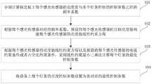
步骤101:分别计算标定板上每个感光传感器的亮度值与多个灯条控制的控制参数之间的斜率系数。具体的,灯条的控制参数为占空比或者电流值,本实施例中计算标定板上每个感光传感器的亮度值与每个灯条控制的占空比或每个感光传感器的亮度值与每个灯条控制的电流值的斜率系数;其中每个灯条控制的占空比指的是用于控制该灯条亮度的占空比,每个灯条控制的电流值指的是用于控制该灯条亮度的电流值。Step 101: Calculate the slope coefficient between the brightness value of each photosensitive sensor on the calibration board and the control parameters controlled by the plurality of light bars. Specifically, the control parameter of the light bar is the duty cycle or the current value. In this embodiment, the brightness value of each photosensitive sensor on the calibration board and the duty cycle controlled by each light bar or the brightness value of each photosensitive sensor and the The slope coefficient of the current value controlled by each light bar; the duty cycle controlled by each light bar refers to the duty cycle used to control the brightness of the light bar, and the current value controlled by each light bar refers to the duty cycle used to control the brightness of the light bar. The current value that controls the brightness of this light bar.
步骤102:根据每个感光传感器对应的斜率系数、预设的每个感光传感器的目标亮度值构建每个感光传感器的亮度值线性约束方程。Step 102: Construct a linear constraint equation of the luminance value of each photosensitive sensor according to the slope coefficient corresponding to each photosensitive sensor and the preset target luminance value of each photosensitive sensor.
步骤103:根据每个感光传感器的亮度值线性约束方程以及预设的每个感光传感器的电流约束条件或者占空比约束条件,采用线性约束最小二乘法计算每个灯条的最优控制参数。Step 103: According to the linear constraint equation of the brightness value of each photosensitive sensor and the preset current constraint condition or duty cycle constraint condition of each photosensitive sensor, use the linear constrained least squares method to calculate the optimal control parameter of each light bar.
步骤104:将设备上每个灯条的亮度控制参数设置为其对应的最优控制参数。Step 104: Set the brightness control parameter of each light bar on the device to its corresponding optimal control parameter.
其中,在步骤101中,在计算每个感光传感器的亮度值与占空比或亮度值与电流值的斜率系数时,应考虑多个灯条对一个感光传感器测量的亮度值的影响,因此对于任意一个感光传感器i,依次打开所有的灯条,其中打开每个灯条时将该灯条的占空比或者电流值由最小调到最大,使得感光传感器检测到的亮度值也是由最小变到最大,在此过程中获取当前感光传感器i的最小亮度值和最大亮度值,将该灯条的占空比或者电流值的最小值和最大值组成的区间划分为N个等分电流值或者占空比区间,N不小于4,例如取5个等分的电流值或占空比b[1]、b[2]、b[3]、b[4]和b[5],对应的将感光传感器i的最小亮度值和最大亮度值组成的区间也划分为N等分亮度区间,例如对应感光传感器的测量值为分为五个等分分别为TP[1]、TP[2]、TP[3]、TP[4]和TP[5],采用最小二乘法根据N个等分电流值或者占空比区间以及N等分亮度区间计算出每个灯条的电流值或占空比与亮度值的子斜率系数,多个灯条与感光传感器i的多个子斜率系数组成斜率系数。例如,当第一个灯条打开时,得到第一个感光传感器对应的子斜率系数为K1,当第二个灯条打开时得到第一个感光传感器对应的子斜率系数为K2,这样得到多个灯条分别打开时的子斜率系数,这些子斜率系数可以按照数组或者集合的形式存储以组成第一个感光传感器的斜率系数。按照此方法可以获取所有感光传感器对应的斜率系数。Among them, in
其中,在步骤102中,根据每个感光传感器的斜率系数、预设的每个感光传感器的目标亮度值计算每个感光传感器的亮度值线性约束方程包括:Wherein, in
对于任意一个感光传感器通过以下公式计算其亮度值:For any photosensitive sensor, its brightness value is calculated by the following formula:

其中,yi表示第i个感光传感器的亮度值,ki,j表示第j个灯条打开时第i个感光传感器对应的子斜率系数,j表示灯条编号,xj表示第j个灯条当前的占空比或电流值。Among them,yi represents the brightness value of the ith photosensitive sensor, ki,j represents the sub-slope coefficient corresponding to the ith photosensitive sensor when the jth light bar is turned on, j represents the number of the light bar, and xj represents the jth lamp The current duty cycle or current value of the bar.
其中,任意一个感光传感器i的亮度值线性约束方程为:Among them, the linear constraint equation of the brightness value of any photosensitive sensor i is:

其中,goal_pow表示感光传感器目标亮度值,5%是设定的上下限阈值,是本领域技术人员根据使用环境预设的,不是固定不变。Wherein, goal_pow represents the target brightness value of the photosensitive sensor, and 5% is the set upper and lower thresholds, which are preset by those skilled in the art according to the usage environment, and are not fixed.
例如编号为1的亮度传感器的亮度值线性约束方程为:For example, the luminance value linear constraint equation of the luminance sensor numbered 1 is:

编号为2的亮度传感器的亮度值线性约束方程为:The linear constraint equation of the brightness value of the brightness sensor numbered 2 is:

编号为3的感光传感器的亮度值线性约束方程为:The linear constraint equation of the brightness value of the photosensitive sensor numbered 3 is:

其中,在步骤103中采用最小二乘法根据每个感光传感器的亮度值线性约束方程以及预设的每个传感器的电流约束条件或者占空比约束条件计算每个灯条的最优电流值或者最优占空比包括:采用最小二乘法对所有感光传感器的亮度值线性约束方程(也可以裂解约束方程)进行求解得到每个灯条对应的最优电流值或者最优占空比。其中,对于任意一个灯条i,其占空比或电流值的约束条件为:Wherein, in
lb≤xjub,lb≤xjub ,
其中,xj表示第j个灯条当前的占空比或电流值,lb为灯条最小占空比值或最小电流值,ub为灯条最大占空比值或最大电流值。Among them, xj represents the current duty cycle or current value of the jth light bar, lb is the minimum duty cycle value or minimum current value of the light bar, and ub is the maximum duty cycle value or maximum current value of the light bar.
其中,本实施例采用最小二乘法对所有感光传感器的亮度值线性约束方程进行求解得到每个灯条对应的最优电流值或者最优占空比时,采用约束线性最小二乘最优求解下列目标方程,得到一个最优占空比或最优电流值组成的集合,该集合中包括多个最优占空比或最优电流值,每个最优占空比或最优电流值对应一个灯条,将对应灯条的占空比或者电流值设置为计算得到的最优占空比或最优电流值。其中,y1,y2,...,yn越向goal_pow收敛,光源均匀性则越高。Wherein, in this embodiment, the least squares method is used to solve the linear constraint equations of the brightness values of all photosensitive sensors to obtain the optimal current value or optimal duty cycle corresponding to each light bar, and the constrained linear least squares method is used to optimally solve the following The objective equation is to obtain a set of optimal duty cycles or optimal current values. The set includes multiple optimal duty cycles or optimal current values, and each optimal duty cycle or optimal current value corresponds to one For the light bar, set the duty cycle or current value of the corresponding light bar to the calculated optimal duty cycle or optimal current value. Among them, the more y1 , y2 , ...,yn converges to the goal_pow, the higher the uniformity of the light source.

min f(x)表示最优占空比或最优电流值,是根据上述约束条件采用最小二乘法计算所得,y1表示第1个感光传感器(也可以理解为编号为1的感光传感器)的亮度值,yn表示第n个感光传感器的亮度值。min f(x) represents the optimal duty cycle or the optimal current value, which is calculated by the least squares method according to the above constraints, and y1 represents the first photosensitive sensor (which can also be understood as the photosensitive sensor numbered 1). Brightness value, yn represents the brightness value of the nth photosensitive sensor.
进一步的,在将设备上每个灯条的电流值设置为其对应的最优电流值或者将每个灯条的占空比设置为其对应的最优占空比之后还包括:计算所有感光传感器当前亮度值的均匀性值,判断该均匀性值是否满足预设的均匀性阈值要求,若不满足则进一步对部分灯条的占空比或电流值进行微调,若满足则停止对灯条的占空比或电流值的调节。Further, after setting the current value of each light bar on the device to its corresponding optimal current value or setting the duty cycle of each light bar to its corresponding optimal duty cycle, the method further includes: calculating all light-sensitive The uniformity value of the current brightness value of the sensor is used to determine whether the uniformity value meets the preset uniformity threshold requirements. If not, the duty cycle or current value of some light bars is further fine-tuned. adjustment of the duty cycle or current value.
其中,本实施例计算所有感光传感器当前亮度值的均匀性值时通过下述公式计算所有感光传感器当前亮度值的均匀性值:Wherein, when the present embodiment calculates the uniformity value of the current brightness value of all photosensitive sensors, the uniformity value of the current brightness value of all photosensitive sensors is calculated by the following formula:

其中,p表示均匀性值,max(光感值)表示所有感光传感器测量值中的最大值,min(光感值)表示所有感光传感器测量值中的最小值,average(光感值)表示所有感光传感器测量值的平均值。Among them, p represents the uniformity value, max (photosensitivity value) represents the maximum value of all photosensitive sensor measurement values, min (photosensitivity value) represents the minimum value of all photosensitive sensor measurement values, and average (photosensitivity value) represents all Average value of light sensor measurements.
其中,本实施例中对对应灯条的占空比或电流值进行微调包括:根据预先设定的灯条和感光传感器的对应关系,这个对应关系是预先认为设定的,例如找到当前亮度值最大的感光传感器,对与该感光传感器之间最大斜率系数对应的灯条的占空比或电流值进行微调。由于多个感光传感器分散设置在光板上各处,每个灯条与每个感光传感器的距离不同,因此每个灯条对每个传感器的影响力也不同,根据这个原理将不同的灯条与对应的感光传感器建立对应的关系,例如第10、11、12号感光传感器的亮度值主要受第三个灯条的影响,换言之,第10、11、12号感光传感器的测量值主要可以反应第三个灯条的亮度。将获取当前检测到的最大亮度值的感光传感器,确定与该感光传感器对应的斜率系数最大的灯条,将该灯条的占空比或电流值减小预设的微调步进值;同时获取当前检测到的最小亮度值的感光传感器,确定与该感光传感器对应的斜率系数最大的灯条,将该灯条的占空比或电流值增大预设的微调步进值,然后进一步重复上述均匀性判定的步骤,若满足预设的均匀性阈值则停止调整各灯条的占空比或者电流值,否则重复上述步骤继续调整各灯条的占空比或电流值,直到所有感光传感器检测到的亮度值满足均匀性要求。The fine-tuning of the duty cycle or current value of the corresponding light bar in this embodiment includes: according to the preset correspondence between the light bar and the photosensitive sensor, the correspondence is pre-defined, for example, finding the current brightness value For the largest photosensitive sensor, fine-tune the duty cycle or current value of the light bar corresponding to the maximum slope coefficient between the photosensitive sensors. Since multiple photosensitive sensors are scattered around the light plate, the distance between each light bar and each photosensitive sensor is different, so the influence of each light bar on each sensor is also different. For example, the brightness values of the 10th, 11th, and 12th photosensitive sensors are mainly affected by the third light bar. In other words, the measured values of the 10th, 11th, and 12th photosensitive sensors can mainly reflect the The brightness of each light bar. The photosensitive sensor with the currently detected maximum brightness value will be obtained, the light bar with the largest slope coefficient corresponding to the photosensitive sensor will be determined, and the duty cycle or current value of the light bar will be reduced by the preset fine-tuning step value; The photosensitive sensor with the currently detected minimum brightness value determines the light bar with the largest slope coefficient corresponding to the photosensitive sensor, increases the duty cycle or current value of the light bar by a preset fine-tuning step value, and then further repeats the above In the step of uniformity determination, if the preset uniformity threshold is met, stop adjusting the duty cycle or current value of each light bar, otherwise repeat the above steps to continue to adjust the duty cycle or current value of each light bar until all photosensitive sensors detect The obtained brightness value meets the uniformity requirements.
其中,本实施例中调节占空比或电流值的微调步进值设置略有不同,若是通过调节电流值改变灯条的亮度,则微调步进值设置为1-10mA之间的任意值,若是通过调节占空比改变灯条的亮度,则调步进值设置为1-10pa。Among them, in this embodiment, the setting of the fine-tuning step value for adjusting the duty cycle or the current value is slightly different. If the brightness of the light bar is changed by adjusting the current value, the fine-tuning step value is set to any value between 1-10mA. If the brightness of the light bar is changed by adjusting the duty cycle, the step value is set to 1-10pa.
实施例二:Embodiment 2:
请参考图3,本实施例提供一种光源均匀性调节系统,包括:Please refer to FIG. 3 , this embodiment provides a light source uniformity adjustment system, including:
第一计算模块201,用于分别计算标定板上每个感光传感器的亮度值与多个灯条控制的控制参数之间的斜率系数。具体的,计算该斜率系数的方法和实施例一种相同。The
第二计算模块202,用于根据每个感光传感器的斜率系数、预设的每个感光传感器的目标亮度值构建每个感光传感器的亮度值线性约束方程;The
第三计算模块203,用于根据每个感光传感器的亮度值线性约束方程以及预设的每个感光传感器的电流约束条件或者占空比约束条件,采用线性约束最小二乘法计算每个灯条的最优控制参数;The
控制模块204,用于将设备上每个灯条的亮度控制参数设置为其对应的最优控制参数。The
进一步的,该光源均匀性调节系统还包括均匀性判断模块205,均匀性判断模块205用于计算所有感光传感器当前亮度值的均匀性值,判断该均匀性值是否满足预设的均匀性阈值要求,若不满足,则进一步对对应的灯条的控制参数进行微调;若满足,则停止对灯条的控制参数的调节。Further, the light source uniformity adjustment system further includes a
通过本实施例的光源均匀性调节系统,本实施例的调节方法可以自动、快速且精准的将标定板各处的亮度值调节均匀,提高了调节效率。Through the light source uniformity adjustment system of this embodiment, the adjustment method of this embodiment can automatically, quickly and accurately adjust the brightness values of all parts of the calibration plate to be uniform, thereby improving the adjustment efficiency.
实施例三
本实施例一种光源均匀性调节装置,如图1,该调节装置包括多个感光传感器1和处理器2,多个感光传感器1均匀设置在标定板上用于测量标定板上不同位置处的亮度值,处理器2通过线缆与多个感光传感器1连接,处理器2用于根据多个感光传感器1亮度值对每个灯条的占空比或电流值进行调节,以使得所有的感光传感器所处位置的亮度达到预设均匀性要求。其中,具体的调节方法和实施例一中相同,此处不再赘述。This embodiment is a light source uniformity adjusting device, as shown in FIG. 1 , the adjusting device includes a plurality of photosensitive sensors 1 and a
以上应用了具体个例对本发明进行阐述,只是用于帮助理解本发明,并不用以限制本发明。对于本发明所属技术领域的技术人员,依据本发明的思想,还可以做出若干简单推演、变形或替换。The above specific examples are used to illustrate the present invention, which are only used to help understand the present invention, and are not intended to limit the present invention. For those skilled in the art to which the present invention pertains, according to the idea of the present invention, several simple deductions, modifications or substitutions can also be made.
Claims (10)
Translated fromChinese


Priority Applications (1)
| Application Number | Priority Date | Filing Date | Title |
|---|---|---|---|
| CN202110116919.7ACN114828355B (en) | 2021-01-28 | 2021-01-28 | A method, system and device for adjusting uniformity of light source |
Applications Claiming Priority (1)
| Application Number | Priority Date | Filing Date | Title |
|---|---|---|---|
| CN202110116919.7ACN114828355B (en) | 2021-01-28 | 2021-01-28 | A method, system and device for adjusting uniformity of light source |
Publications (2)
| Publication Number | Publication Date |
|---|---|
| CN114828355Atrue CN114828355A (en) | 2022-07-29 |
| CN114828355B CN114828355B (en) | 2025-03-14 |
Family
ID=82525952
Family Applications (1)
| Application Number | Title | Priority Date | Filing Date |
|---|---|---|---|
| CN202110116919.7AActiveCN114828355B (en) | 2021-01-28 | 2021-01-28 | A method, system and device for adjusting uniformity of light source |
Country Status (1)
| Country | Link |
|---|---|
| CN (1) | CN114828355B (en) |
Cited By (4)
| Publication number | Priority date | Publication date | Assignee | Title |
|---|---|---|---|---|
| CN115237183A (en)* | 2022-09-19 | 2022-10-25 | 苏州天准科技股份有限公司 | Illumination adjusting device and detection system |
| CN115696671A (en)* | 2022-11-01 | 2023-02-03 | 凌云天博光电科技股份有限公司 | Light source illumination adjusting method and device, computer equipment and medium |
| CN116466522A (en)* | 2023-04-13 | 2023-07-21 | 南京华生皓光电科技有限公司 | A control device and system with automatic dimming |
| CN119322460A (en)* | 2024-12-19 | 2025-01-17 | 东莞康视达自动化科技有限公司 | Self-adaptive adjustment method and device for parameters of analog light source controller |
Citations (5)
| Publication number | Priority date | Publication date | Assignee | Title |
|---|---|---|---|---|
| CN101350933A (en)* | 2008-09-02 | 2009-01-21 | 广东威创视讯科技股份有限公司 | Method for regulating lighteness of filmed display screen based on image inductor |
| CN102347014A (en)* | 2011-10-25 | 2012-02-08 | 中兴通讯股份有限公司 | Method and device for adjusting backlight brightness of display panel |
| CN106444301A (en)* | 2016-11-21 | 2017-02-22 | 北京理工大学 | Source optimization method by adopting self-adaptive compressed sensing technology |
| CN107148127A (en)* | 2017-07-21 | 2017-09-08 | 肖旭华 | A kind of method of automatic detection power supply to be measured or dimming light source performance |
| WO2018033340A1 (en)* | 2016-08-16 | 2018-02-22 | Osram Gmbh | Method for producing a traffic route lighting device |
- 2021
- 2021-01-28CNCN202110116919.7Apatent/CN114828355B/enactiveActive
Patent Citations (5)
| Publication number | Priority date | Publication date | Assignee | Title |
|---|---|---|---|---|
| CN101350933A (en)* | 2008-09-02 | 2009-01-21 | 广东威创视讯科技股份有限公司 | Method for regulating lighteness of filmed display screen based on image inductor |
| CN102347014A (en)* | 2011-10-25 | 2012-02-08 | 中兴通讯股份有限公司 | Method and device for adjusting backlight brightness of display panel |
| WO2018033340A1 (en)* | 2016-08-16 | 2018-02-22 | Osram Gmbh | Method for producing a traffic route lighting device |
| CN106444301A (en)* | 2016-11-21 | 2017-02-22 | 北京理工大学 | Source optimization method by adopting self-adaptive compressed sensing technology |
| CN107148127A (en)* | 2017-07-21 | 2017-09-08 | 肖旭华 | A kind of method of automatic detection power supply to be measured or dimming light source performance |
Cited By (6)
| Publication number | Priority date | Publication date | Assignee | Title |
|---|---|---|---|---|
| CN115237183A (en)* | 2022-09-19 | 2022-10-25 | 苏州天准科技股份有限公司 | Illumination adjusting device and detection system |
| CN115237183B (en)* | 2022-09-19 | 2022-12-02 | 苏州天准科技股份有限公司 | Illumination adjusting device and detection system |
| CN115696671A (en)* | 2022-11-01 | 2023-02-03 | 凌云天博光电科技股份有限公司 | Light source illumination adjusting method and device, computer equipment and medium |
| CN115696671B (en)* | 2022-11-01 | 2025-06-06 | 凌云天博光电科技股份有限公司 | Light source illumination adjustment method, device, computer equipment and medium |
| CN116466522A (en)* | 2023-04-13 | 2023-07-21 | 南京华生皓光电科技有限公司 | A control device and system with automatic dimming |
| CN119322460A (en)* | 2024-12-19 | 2025-01-17 | 东莞康视达自动化科技有限公司 | Self-adaptive adjustment method and device for parameters of analog light source controller |
Also Published As
| Publication number | Publication date |
|---|---|
| CN114828355B (en) | 2025-03-14 |
Similar Documents
| Publication | Publication Date | Title |
|---|---|---|
| CN114828355A (en) | Light source uniformity adjusting method, system and device | |
| TWI507971B (en) | Display parameter adjustment method and system | |
| CN109451289B (en) | Method and system for detecting and correcting projector | |
| WO2014110191A1 (en) | Lighting system characterization | |
| CN109191374B (en) | Distortion parameter measurement method, device and system | |
| JP2012503217A (en) | Method for white balance of LED backlight | |
| CN111637838A (en) | Height difference detection method, height difference detection device, storage medium and electronic equipment | |
| WO2015100757A1 (en) | Lcd full greyscale data acquisition method based on ccd camera | |
| CN111757097A (en) | Detection method, detection device and computer readable storage medium | |
| TW201839367A (en) | Thermal detection device | |
| CN110695520A (en) | Vision-based full-automatic galvanometer field calibration system and calibration method thereof | |
| CN112361989B (en) | Method for calibrating parameters of measurement system through point cloud uniformity consideration | |
| CN109191386B (en) | BPNN-based rapid Gamma correction method and device | |
| CN101635130A (en) | System and method for adjusting brightness point by point | |
| CN113936621B (en) | Correction method and related device for LCD display screen P-gamma | |
| CN119007633A (en) | Color debugging and correcting method and system based on LED display screen | |
| CN114530119A (en) | Correction coefficient correction method, device and system based on gray scale | |
| CN109119031A (en) | Method and device for controlling output brightness of display screen and electronic equipment | |
| CN110780478B (en) | Liquid crystal screen calibration detection method | |
| CN113450736A (en) | Display correction system and display correction method | |
| WO2022077764A1 (en) | Display panel brightness adjustment method and apparatus | |
| CN114324383B (en) | Connector detection method, device and system | |
| CN106323514A (en) | Transparent material stress measuring device based on IPS-DGS method | |
| CN100428049C (en) | Optical center monitoring device and method | |
| KR100842460B1 (en) | Dot defect detection method of flat panel display panel |
Legal Events
| Date | Code | Title | Description |
|---|---|---|---|
| PB01 | Publication | ||
| PB01 | Publication | ||
| SE01 | Entry into force of request for substantive examination | ||
| SE01 | Entry into force of request for substantive examination | ||
| GR01 | Patent grant | ||
| GR01 | Patent grant |