CN114824943A - Connector connecting structure and connector thereof - Google Patents
Connector connecting structure and connector thereofDownload PDFInfo
- Publication number
- CN114824943A CN114824943ACN202110064482.7ACN202110064482ACN114824943ACN 114824943 ACN114824943 ACN 114824943ACN 202110064482 ACN202110064482 ACN 202110064482ACN 114824943 ACN114824943 ACN 114824943A
- Authority
- CN
- China
- Prior art keywords
- engaging arm
- connector
- engaging
- arm
- connection structure
- Prior art date
- Legal status (The legal status is an assumption and is not a legal conclusion. Google has not performed a legal analysis and makes no representation as to the accuracy of the status listed.)
- Granted
Links
- 230000008878couplingEffects0.000claims1
- 238000010168coupling processMethods0.000claims1
- 238000005859coupling reactionMethods0.000claims1
- 230000000903blocking effectEffects0.000description1
- 238000000034methodMethods0.000description1
- 238000012986modificationMethods0.000description1
- 230000004048modificationEffects0.000description1
- NJPPVKZQTLUDBO-UHFFFAOYSA-NnovaluronChemical compoundC1=C(Cl)C(OC(F)(F)C(OC(F)(F)F)F)=CC=C1NC(=O)NC(=O)C1=C(F)C=CC=C1FNJPPVKZQTLUDBO-UHFFFAOYSA-N0.000description1
Images


Classifications
- H—ELECTRICITY
- H01—ELECTRIC ELEMENTS
- H01R—ELECTRICALLY-CONDUCTIVE CONNECTIONS; STRUCTURAL ASSOCIATIONS OF A PLURALITY OF MUTUALLY-INSULATED ELECTRICAL CONNECTING ELEMENTS; COUPLING DEVICES; CURRENT COLLECTORS
- H01R13/00—Details of coupling devices of the kinds covered by groups H01R12/70 or H01R24/00 - H01R33/00
- H01R13/62—Means for facilitating engagement or disengagement of coupling parts or for holding them in engagement
- H01R13/639—Additional means for holding or locking coupling parts together, after engagement, e.g. separate keylock, retainer strap
- H—ELECTRICITY
- H01—ELECTRIC ELEMENTS
- H01R—ELECTRICALLY-CONDUCTIVE CONNECTIONS; STRUCTURAL ASSOCIATIONS OF A PLURALITY OF MUTUALLY-INSULATED ELECTRICAL CONNECTING ELEMENTS; COUPLING DEVICES; CURRENT COLLECTORS
- H01R24/00—Two-part coupling devices, or either of their cooperating parts, characterised by their overall structure
- H01R24/20—Coupling parts carrying sockets, clips or analogous contacts and secured only to wire or cable
- H—ELECTRICITY
- H01—ELECTRIC ELEMENTS
- H01R—ELECTRICALLY-CONDUCTIVE CONNECTIONS; STRUCTURAL ASSOCIATIONS OF A PLURALITY OF MUTUALLY-INSULATED ELECTRICAL CONNECTING ELEMENTS; COUPLING DEVICES; CURRENT COLLECTORS
- H01R2201/00—Connectors or connections adapted for particular applications
- H01R2201/26—Connectors or connections adapted for particular applications for vehicles
Landscapes
- Details Of Connecting Devices For Male And Female Coupling (AREA)
Abstract
Description
Translated fromChinese技术领域technical field
本发明涉及一种连接器连接结构,尤其涉及一种具有卡合臂的连接器连接结构及其连接器。The invention relates to a connector connection structure, in particular to a connector connection structure with a snap arm and a connector thereof.
背景技术Background technique
公知的电子产品,例如行车记录器,以适配器(adapter)提供电力,行车记录器的缆线具有一第一连接器,适配器的缆线具有一第二连接器,第一连接器与第二连接器彼此相连。然而由于车辆在行驶时会有震动问题,也可能会有使用者不慎拉扯缆线的情形,导致第一连接器与第二连接器分离,因此有需要进行额外设计而防止第一连接器从第二连接器意外脱落。A well-known electronic product, such as a driving recorder, is powered by an adapter. The cable of the driving recorder has a first connector, the cable of the adapter has a second connector, and the first connector is connected with the second connector. devices are connected to each other. However, due to the vibration problem when the vehicle is driving, there may also be situations where the user accidentally pulls the cable, causing the first connector and the second connector to be separated. Therefore, additional design is required to prevent the first connector from The second connector came off accidentally.
因此,需要提供一种具有卡合臂的连接器连接结构以及连接器来解决上述问题。Therefore, it is necessary to provide a connector connecting structure with a snap arm and a connector to solve the above problems.
发明内容SUMMARY OF THE INVENTION
本发明的实施例是为了解决公知技术的问题而提供的一种连接器连接结构,其包括一第一连接器以及一第二连接器。该第一连接器包括一第一连接头以及至少一卡合部。该第二连接器包括一壳体、一第二连接头以及至少一卡合臂,该第二连接头以及该至少一卡合臂设于该壳体之内,该至少一卡合臂适于在一第一卡合臂位置以及一第二卡合臂位置之间转动,该第一连接头适于插入于该壳体之内以连接该第二连接头,当该至少一卡合臂位于该第一卡合臂位置时,该至少一卡合臂适于卡合该至少一卡合部,当该至少一卡合臂位于该第二卡合臂位置时,该至少一卡合臂适于释放该至少一卡合部。The embodiment of the present invention provides a connector connection structure to solve the problem of the known technology, which includes a first connector and a second connector. The first connector includes a first connector and at least one engaging portion. The second connector includes a housing, a second connector and at least one engaging arm, the second connector and the at least one engaging arm are arranged in the housing, and the at least one engaging arm is suitable for Rotating between a first engaging arm position and a second engaging arm position, the first connector is adapted to be inserted into the housing to connect with the second connector, when the at least one engaging arm is located at When the first engaging arm is in the position, the at least one engaging arm is suitable for engaging the at least one engaging portion, and when the at least one engaging arm is in the second engaging arm position, the at least one engaging arm is suitable for engaging the at least one engaging portion. to release the at least one engaging portion.
在一实施例中,该第二连接器还包括一操作部以及一弹力单元,该操作部连接该至少一卡合臂,该弹力单元连接该至少一卡合臂,该操作部适于接受使用者的操作而推使该至少一卡合臂从该第一卡合臂位置移动至该第二卡合臂位置,该弹力单元对该至少一卡合臂提供一弹性力,以使该至少一卡合臂倾向从该第二卡合臂位置移动至该第一卡合臂位置。In one embodiment, the second connector further includes an operating portion and an elastic force unit, the operating portion is connected to the at least one engaging arm, the elastic force unit is connected to the at least one engaging arm, and the operating portion is suitable for accepting use The operation of the operator pushes the at least one engaging arm to move from the first engaging arm position to the second engaging arm position, and the elastic force unit provides an elastic force to the at least one engaging arm to make the at least one engaging arm move. The engagement arm tends to move from the second engagement arm position to the first engagement arm position.
在一实施例中,该至少一卡合臂包括一卡勾、一卡合臂枢接部以及一杆体段部,该至少一卡合臂通过该卡合臂枢接部枢接该壳体,该卡勾适于卡合该至少一卡合部,该卡合臂枢接部位于该卡勾与该杆体段部之间,该操作部以及该弹力单元连接该杆体段部。In one embodiment, the at least one engaging arm includes a hook, a pivoting portion of the engaging arm and a rod body section, and the at least one engaging arm is pivotally connected to the casing through the pivoting portion of the engaging arm, The hook is suitable for engaging with the at least one engaging portion, the pivoting portion of the engaging arm is located between the hook and the rod body segment, and the operating portion and the elastic unit are connected to the rod body segment.
在一实施例中,该第一连接头适于沿一第一方向插入于该壳体之内以连接该第二连接头,该操作部适于沿一第二方向被推压以使该至少一卡合臂从该第一卡合臂位置移动至该第二卡合臂位置,该第一方向垂直于该第二方向。In one embodiment, the first connector is adapted to be inserted into the housing along a first direction to connect with the second connector, and the operating portion is adapted to be pushed along a second direction so that the at least An engaging arm moves from the first engaging arm position to the second engaging arm position, and the first direction is perpendicular to the second direction.
在一实施例中,该壳体还包括一挡墙,该弹力单元设于该杆体段部与该挡墙之间,当该操作部沿该第二方向被推压时,该弹力单元朝该挡墙被推压以产生该弹性力。In one embodiment, the housing further includes a retaining wall, the elastic unit is arranged between the rod body section and the retaining wall, when the operating portion is pushed along the second direction, the elastic unit moves toward the The retaining wall is pushed to generate this elastic force.
在一实施例中,该弹力单元包括一弧状弹片,至少该弧状弹片的一端连接该杆体段部。In one embodiment, the elastic unit includes an arc-shaped elastic piece, and at least one end of the arc-shaped elastic piece is connected to the rod body section.
在一实施例中,该操作部、该弹力单元以及该至少一卡合臂以一体成形的方式形成。In one embodiment, the operating portion, the elastic unit and the at least one engaging arm are formed in one piece.
在一实施例中,该壳体还包括一壳体限位槽,该操作部至少部分在该壳体限位槽中移动。In one embodiment, the housing further includes a housing limiting groove, and the operating portion at least partially moves in the housing limiting groove.
在一实施例中,该第二连接器还包括一基座以及一操作部,该至少一卡合臂包括一卡勾,该至少一卡合臂的一端连接该基座,该卡勾形成于该至少一卡合臂的另一端,该操作部连接该至少一卡合臂,该操作部适于接受使用者的操作而推使该至少一卡合臂从该第一卡合臂位置移动至该第二卡合臂位置,该至少一卡合臂本身提供一弹性力,以使该至少一卡合臂倾向从该第二卡合臂位置移动至该第一卡合臂位置。In one embodiment, the second connector further includes a base and an operating portion, the at least one engaging arm includes a hook, one end of the at least one engaging arm is connected to the base, and the hook is formed on the base. At the other end of the at least one engaging arm, the operating portion is connected to the at least one engaging arm, and the operating portion is adapted to accept the operation of the user to push the at least one engaging arm to move from the position of the first engaging arm to the position of the first engaging arm. In the second engagement arm position, the at least one engagement arm itself provides an elastic force, so that the at least one engagement arm tends to move from the second engagement arm position to the first engagement arm position.
在一实施例中,该第一连接头适于沿一第一方向插入于该壳体之内以连接该第二连接头,该操作部适于沿一第二方向被推压以使该至少一卡合臂从该第一卡合臂位置移动至该第二卡合臂位置,该第一方向垂直于该第二方向。In one embodiment, the first connector is adapted to be inserted into the housing along a first direction to connect with the second connector, and the operating portion is adapted to be pushed along a second direction so that the at least An engaging arm moves from the first engaging arm position to the second engaging arm position, and the first direction is perpendicular to the second direction.
在一实施例中,该至少一卡合臂、该基座以及该操作部以一体成形的方式形成。In one embodiment, the at least one engaging arm, the base and the operating portion are formed in one piece.
在一实施例中,该至少一卡合臂包括一第一段部以及一第二段部,该第一段部连接该操作部以及该卡勾,该第二段部连接该操作部以及该基座,该第一段部的长度大于该第二段部的长度。In one embodiment, the at least one engaging arm includes a first segment and a second segment, the first segment is connected to the operating portion and the hook, and the second segment is connected to the operating portion and the hook. In the base, the length of the first segment is greater than the length of the second segment.
在一实施例中,该第一段部的厚度大于该第二段部的厚度。In one embodiment, the thickness of the first segment is greater than the thickness of the second segment.
在一实施例中,该第二段部呈弧形。In one embodiment, the second segment is arc-shaped.
在一实施例中,该壳体包括一壳体限位肋,该基座包括一基座限位槽,该基座限位槽嵌合该壳体限位肋。In one embodiment, the casing includes a casing limiting rib, the base includes a base limiting groove, and the base limiting groove engages with the casing limiting rib.
在一实施例中,该第二连接器还包括一电路板以及一缆线,该电路板设于该壳体之中,该缆线耦接该电路板,该基座包括一基座开口,该缆线穿过该基座开口。In one embodiment, the second connector further includes a circuit board and a cable, the circuit board is disposed in the housing, the cable is coupled to the circuit board, the base includes a base opening, The cable passes through the base opening.
在一实施例中,本发明提供一种连接器(即前述的第二连接器),其包括一壳体、一连接头以及至少一卡合臂。该连接头以及该至少一卡合臂设于该壳体之内,该至少一卡合臂适于在一第一卡合臂位置以及一第二卡合臂位置之间转动。In one embodiment, the present invention provides a connector (ie, the aforementioned second connector), which includes a housing, a connector, and at least one engaging arm. The connector and the at least one engaging arm are arranged in the casing, and the at least one engaging arm is adapted to rotate between a first engaging arm position and a second engaging arm position.
在本发明实施例的连接器连接结构中,由于卡合臂适于卡合卡合部,因此可加强第一连接器与第二连接器之间的连结,避免第一连接器从第二连接器意外脱落。此外,在本发明的第一实施例中,操作部、弹力单元以及卡合臂以一体成形的方式形成,因此结构简单、成本低廉、组装容易。同样的,在本发明的第二实施例中,卡合臂、基座以及操作部以一体成形的方式形成,因此同样具有结构简单、成本低廉、组装容易等优点。而当使用者欲分离第一连接器以及第二连接器时,仅需要简单按压操作部,即可轻松的使第一连接器脱离第二连接器,操作方便。In the connector connection structure of the embodiment of the present invention, since the engaging arm is suitable for engaging the engaging portion, the connection between the first connector and the second connector can be strengthened, and the connection between the first connector and the second connector can be avoided. The device fell off unexpectedly. In addition, in the first embodiment of the present invention, the operation portion, the elastic force unit and the engaging arm are integrally formed, so the structure is simple, the cost is low, and the assembly is easy. Likewise, in the second embodiment of the present invention, the engaging arm, the base, and the operating portion are formed in one piece, and thus also have the advantages of simple structure, low cost, and easy assembly. When the user wants to separate the first connector and the second connector, the first connector can be easily separated from the second connector by simply pressing the operation part, which is convenient to operate.
附图说明Description of drawings
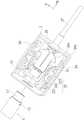
图1显示本发明第一实施例的连接器连接结构,其中,第一连接器尚未连接第二连接器。FIG. 1 shows a connector connection structure according to a first embodiment of the present invention, wherein the first connector has not yet been connected to the second connector.
图2A显示本发明第一实施例的连接器连接结构的组合图,其中,卡合臂处于第一卡合臂位置。2A shows a combined view of the connector connection structure according to the first embodiment of the present invention, wherein the engaging arm is at the first engaging arm position.
图2B显示本发明第一实施例的连接器连接结构的组合图,其中,卡合臂处于第二卡合臂位置。2B shows a combined view of the connector connection structure according to the first embodiment of the present invention, wherein the engaging arm is in the second engaging arm position.
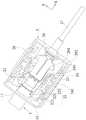
图3显示本发明第二实施例的连接器连接结构,其中,第一连接器尚未连接第二连接器。FIG. 3 shows a connector connection structure according to a second embodiment of the present invention, wherein the first connector has not yet been connected to the second connector.
图4A显示本发明第二实施例的连接器连接结构的组合图,其中,卡合臂处于第一卡合臂位置。4A shows a combined view of the connector connection structure according to the second embodiment of the present invention, wherein the engaging arm is in the first engaging arm position.
图4B显示本发明第二实施例的连接器连接结构的组合图,其中,卡合臂处于第二卡合臂位置。4B shows a combined view of the connector connection structure according to the second embodiment of the present invention, wherein the engaging arm is in the second engaging arm position.
主要组件符号说明:Explanation of main component symbols:
1 第一连接器1 first connector
11 第一连接头11 The first connector
12 卡合部12 Engagement part
2 第二连接器2 Second connector
21 第二连接头21 Second connector
22 卡合臂22 Engagement arm
221 卡勾221 hook
222 卡合臂枢接部222 Engagement arm pivot
223 杆体段部223 Rod segment
23 操作部23 Operation section
24 弹力单元24 spring units
241 定位凸点241 Positioning bump
27 缆线27 cables
28 电路板28 circuit boards
29 壳体29 Housing
291 挡墙291 Retaining Wall
292 壳体限位槽292 Housing limit slot
293 挡墙凹陷部293 Retaining Wall Recess
3 第一连接器3 First connector
31 第一连接头31 First connector
32 卡合部32 Engagement part
4 第二连接器4 Second connector
41 第二连接头41 Second connector
42 卡合臂42 Engagement arm
421 卡勾421 hook
42A 第一段部42A First paragraph
42B 第二段部42B Second Section
43 操作部43 Operation section
44 基座44 base
441 基座限位槽441 Base limit slot
442 基座开口442 Pedestal opening
47 缆线47 Cable
48 电路板48 circuit boards
49 壳体49 Housing
491 壳体限位肋491 Shell limit rib
X 第一方向X first direction
Y 第二方向Y second direction
具体实施方式Detailed ways
图1显示本发明第一实施例的连接器连接结构,其中,第一连接器尚未连接第二连接器。图2A显示本发明第一实施例的连接器连接结构的组合图,其中,卡合臂处于第一卡合臂位置。图2B显示本发明第一实施例的连接器连接结构的组合图,其中,卡合臂处于第二卡合臂位置。搭配参照图1、图2A以及图2B,本发明第一实施例的连接器连接结构包括一第一连接器1以及一第二连接器2。该第一连接器1包括一第一连接头11以及至少一卡合部12。该第二连接器2包括一壳体29、一第二连接头21以及至少一卡合臂22,该第二连接头21以及该卡合臂22设于该壳体29之内,该卡合臂22适于在一第一卡合臂位置(图2A)以及一第二卡合臂位置(图2B)之间转动,该第一连接头11适于插入于该壳体29之内以连接该第二连接头21。当该卡合臂22位于该第一卡合臂位置时(图2A),该卡合臂22适于卡合该卡合部12。当该卡合臂22位于该第二卡合臂位置时(图2B),该卡合臂22适于释放该卡合部12。FIG. 1 shows a connector connection structure according to a first embodiment of the present invention, wherein the first connector has not yet been connected to the second connector. 2A shows a combined view of the connector connection structure according to the first embodiment of the present invention, wherein the engaging arm is at the first engaging arm position. 2B shows a combined view of the connector connection structure according to the first embodiment of the present invention, wherein the engaging arm is in the second engaging arm position. Referring to FIG. 1 , FIG. 2A and FIG. 2B together, the connector connection structure of the first embodiment of the present invention includes a first connector 1 and a second connector 2 . The first connector 1 includes a
搭配参照图1、图2A以及图2B,在一实施例中,该第二连接器2还包括一操作部23以及一弹力单元24,该操作部23连接该卡合臂22,该弹力单元24连接该卡合臂22,该操作部23适于接受使用者的操作而推使该卡合臂22从该第一卡合臂位置移动至该第二卡合臂位置。该弹力单元24对该卡合臂22提供一弹性力,以使该卡合臂22倾向从该第二卡合臂位置移动至该第一卡合臂位置。Referring to FIG. 1 , FIG. 2A and FIG. 2B , in one embodiment, the second connector 2 further includes an
搭配参照图1、图2A以及图2B,在一实施例中,该卡合臂22包括一卡勾221、一卡合臂枢接部222以及一杆体段部223,该卡合臂22通过该卡合臂枢接部222枢接该壳体29,该卡勾221适于卡合该卡合部12,该卡合臂枢接部222位于该卡勾221与该杆体段部223之间,该操作部23以及该弹力单元24连接该杆体段部223。Referring to FIG. 1 , FIG. 2A and FIG. 2B , in one embodiment, the engaging
搭配参照图1、图2A以及图2B,在一实施例中,该第一连接头11适于沿一第一方向X插入于该壳体29之内以连接该第二连接头21,该操作部23适于沿一第二方向Y被推压以使该卡合臂22从该第一卡合臂位置移动至该第二卡合臂位置,该第一方向X垂直于该第二方向Y。Referring to FIG. 1 , FIG. 2A and FIG. 2B , in one embodiment, the
搭配参照图1、图2A以及图2B,在一实施例中,该壳体29还包括一挡墙291,该弹力单元24设于该杆体段部223与该挡墙291之间,当该操作部23沿该第二方向Y被推压时,该弹力单元24朝该挡墙291被推压以产生该弹性力。Referring to FIG. 1 , FIG. 2A and FIG. 2B , in one embodiment, the
搭配参照图1、图2A以及图2B,在一实施例中,该弹力单元24为一弧状弹片,至少该弧状弹片的一端连接该杆体段部223。在一实施例中,该弹力单元24还包括一定位凸点241,该挡墙291还包括一挡墙凹陷部293,该定位凸点241嵌合该挡墙凹陷部293,藉此限制该弹力单元24的位置。Referring to FIG. 1 , FIG. 2A and FIG. 2B , in one embodiment, the
搭配参照图1、图2A以及图2B,在一实施例中,该操作部23、该弹力单元24以及该卡合臂22以一体成形的方式形成。Referring to FIG. 1 , FIG. 2A and FIG. 2B , in one embodiment, the operating
搭配参照图1、图2A以及图2B,在一实施例中,该壳体29还包括一壳体限位槽292,该操作部23至少部分在该壳体限位槽292中移动,藉此该操作部23沿该第二方向Y移动。Referring to FIG. 1 , FIG. 2A and FIG. 2B , in one embodiment, the
搭配参照图1、图2A以及图2B,在一实施例中,该第二连接器2还包括一电路板28以及一缆线27,该电路板28设于该壳体29之中,该缆线27耦接该电路板28。该第二连接头21设于该电路板28之上。Referring to FIG. 1 , FIG. 2A and FIG. 2B , in one embodiment, the second connector 2 further includes a
图3显示本发明第二实施例的连接器连接结构,其中,第一连接器尚未连接第二连接器。图4A显示本发明第二实施例的连接器连接结构的组合图,其中,卡合臂处于第一卡合臂位置。图4B显示本发明第二实施例的连接器连接结构的组合图,其中,卡合臂处于第二卡合臂位置。搭配参照图3、图4A以及图4B,本发明第二实施例的连接器连接结构包括一第一连接器3以及一第二连接器4。该第一连接器3包括一第一连接头31以及至少一卡合部32。该第二连接器4包括一壳体49、一第二连接头41以及至少一卡合臂42,该第二连接头41以及该卡合臂42设于该壳体49之内,该卡合臂42适于在一第一卡合臂位置(图4A)以及一第二卡合臂位置(图4B)之间转动。该第一连接头31适于插入于该壳体49之内以连接该第二连接头41。当该卡合臂42位于该第一卡合臂位置时(图4A),该卡合臂42适于卡合该卡合部32。当该卡合臂42位于该第二卡合臂位置时(图4B),该卡合臂42适于释放该卡合部32。FIG. 3 shows a connector connection structure according to a second embodiment of the present invention, wherein the first connector has not yet been connected to the second connector. 4A shows a combined view of the connector connection structure according to the second embodiment of the present invention, wherein the engaging arm is in the first engaging arm position. 4B shows a combined view of the connector connection structure according to the second embodiment of the present invention, wherein the engaging arm is in the second engaging arm position. Referring to FIG. 3 , FIG. 4A and FIG. 4B together, the connector connection structure of the second embodiment of the present invention includes a
搭配参照图3、图4A以及图4B,在一实施例中,该第二连接器4还包括一基座44以及一操作部43,该卡合臂42包括一卡勾421,该卡合臂42的一端连接该基座44,该卡勾421形成于该卡合臂42的另一端,该操作部43连接该卡合臂42,该操作部43适于接受使用者的操作而推使该卡合臂42从该第一卡合臂位置(图4A)移动至该第二卡合臂位置(图4B),该卡合臂42本身提供一弹性力,以使该卡合臂42倾向从该第二卡合臂位置(图4B)移动至该第一卡合臂位置(图4A)。3, 4A and 4B, in one embodiment, the
搭配参照图3、图4A以及图4B,在一实施例中,该第一连接头31适于沿一第一方向X插入于该壳体49之内以连接该第二连接头41,该操作部43适于沿一第二方向Y被推压以使该卡合臂42从该第一卡合臂位置移动至该第二卡合臂位置,该第一方向X垂直于该第二方向Y。Referring to FIG. 3 , FIG. 4A and FIG. 4B , in one embodiment, the
搭配参照图3、图4A以及图4B,在一实施例中,该卡合臂42、该基座44以及该操作部43以一体成形的方式形成。Referring to FIG. 3 , FIG. 4A and FIG. 4B , in one embodiment, the engaging
搭配参照图3、图4A以及图4B,在一实施例中,该卡合臂42包括一第一段部42A以及一第二段部42B,该第一段部42A连接该操作部43以及该卡勾421,该第二段部42B连接该操作部43以及该基座44,该第一段部42A的长度大于该第二段部42B的长度。在一实施例中,该第一段部42A的厚度大于该第二段部42B的厚度。该第二段部42B呈弧形。Referring to FIG. 3 , FIG. 4A and FIG. 4B , in one embodiment, the engaging
搭配参照图3、图4A以及图4B,在一实施例中,该壳体49包括一壳体限位肋491,该基座44包括一基座限位槽441,该基座限位槽441嵌合该壳体限位肋491。Referring to FIG. 3 , FIG. 4A and FIG. 4B , in one embodiment, the
搭配参照图3、图4A以及图4B,在一实施例中,该第二连接器4还包括一电路板48以及一缆线47,该电路板48设于该壳体49之中,该缆线47耦接该电路板48。该第二连接头41设于该电路板48之上。该基座44包括一基座开口442,该缆线47穿过该基座开口442。Referring to FIG. 3 , FIG. 4A and FIG. 4B , in one embodiment, the
在本发明实施例的连接器连接结构中,由于卡合臂适于卡合卡合部,因此可加强第一连接器与第二连接器之间的连结,避免第一连接器从第二连接器意外脱落。此外,在本发明的第一实施例中,操作部、弹力单元以及卡合臂以一体成形的方式形成,因此结构简单、成本低廉、组装容易。同样的,在本发明的第二实施例中,卡合臂、基座以及操作部以一体成形的方式形成,因此同样具有结构简单、成本低廉、组装容易等优点。而当使用者欲分离第一连接器以及第二连接器时,仅需要简单按压操作部,即可轻松的使第一连接器脱离第二连接器,操作方便。In the connector connection structure of the embodiment of the present invention, since the engaging arm is suitable for engaging the engaging portion, the connection between the first connector and the second connector can be strengthened, and the connection between the first connector and the second connector can be avoided. The device fell off unexpectedly. In addition, in the first embodiment of the present invention, the operation portion, the elastic force unit and the engaging arm are integrally formed, so the structure is simple, the cost is low, and the assembly is easy. Likewise, in the second embodiment of the present invention, the engaging arm, the base, and the operating portion are formed in one piece, and thus also have the advantages of simple structure, low cost, and easy assembly. When the user wants to separate the first connector and the second connector, the first connector can be easily separated from the second connector by simply pressing the operation part, which is convenient to operate.
虽然本发明已以具体的较佳实施例公开如上,然而其并非用以限定本发明,任何本领域技术人员,在不脱离本发明的精神和范围的情况下,仍可作些许的更动与润饰。因此,本发明的保护范围应当视所附的权利要求书的范围所界定者为准。Although the present invention has been disclosed above with specific preferred embodiments, it is not intended to limit the present invention. Any person skilled in the art can still make some changes and modifications without departing from the spirit and scope of the present invention. retouch. Accordingly, the protection scope of the present invention should be determined by the scope of the appended claims.
Claims (20)
Priority Applications (1)
| Application Number | Priority Date | Filing Date | Title |
|---|---|---|---|
| CN202110064482.7ACN114824943B (en) | 2021-01-18 | 2021-01-18 | Connector connection structure and connector thereof |
Applications Claiming Priority (1)
| Application Number | Priority Date | Filing Date | Title |
|---|---|---|---|
| CN202110064482.7ACN114824943B (en) | 2021-01-18 | 2021-01-18 | Connector connection structure and connector thereof |
Publications (2)
| Publication Number | Publication Date |
|---|---|
| CN114824943Atrue CN114824943A (en) | 2022-07-29 |
| CN114824943B CN114824943B (en) | 2023-12-01 |
Family
ID=82524500
Family Applications (1)
| Application Number | Title | Priority Date | Filing Date |
|---|---|---|---|
| CN202110064482.7AActiveCN114824943B (en) | 2021-01-18 | 2021-01-18 | Connector connection structure and connector thereof |
Country Status (1)
| Country | Link |
|---|---|
| CN (1) | CN114824943B (en) |
Citations (10)
| Publication number | Priority date | Publication date | Assignee | Title |
|---|---|---|---|---|
| JPH10189137A (en)* | 1996-12-26 | 1998-07-21 | Furukawa Electric Co Ltd:The | Connector housing |
| DE19828636A1 (en)* | 1998-06-26 | 2000-01-05 | Framatome Connectors Int | Snap-in connector |
| US20070232115A1 (en)* | 2006-03-29 | 2007-10-04 | Fluke Corporation | Quick-release connector |
| TW201020405A (en)* | 2008-11-28 | 2010-06-01 | Inventec Corp | Lock structure |
| JP2012043739A (en)* | 2010-08-23 | 2012-03-01 | Yazaki Corp | Connector |
| JP2012054009A (en)* | 2010-08-31 | 2012-03-15 | Hirose Electric Co Ltd | Connector |
| CN203225406U (en)* | 2013-05-13 | 2013-10-02 | 纬创资通股份有限公司 | Connection port, clamping assembly and connector module |
| CN205070027U (en)* | 2015-09-25 | 2016-03-02 | 富士康(昆山)电脑接插件有限公司 | Cable connector module |
| CN205724200U (en)* | 2016-05-27 | 2016-11-23 | 立讯精密工业股份有限公司 | electrical connector |
| CN208271106U (en)* | 2018-06-12 | 2018-12-21 | 纬颖科技服务股份有限公司 | Electronic device with removable structure |
- 2021
- 2021-01-18CNCN202110064482.7Apatent/CN114824943B/enactiveActive
Patent Citations (11)
| Publication number | Priority date | Publication date | Assignee | Title |
|---|---|---|---|---|
| JPH10189137A (en)* | 1996-12-26 | 1998-07-21 | Furukawa Electric Co Ltd:The | Connector housing |
| DE19828636A1 (en)* | 1998-06-26 | 2000-01-05 | Framatome Connectors Int | Snap-in connector |
| US20070232115A1 (en)* | 2006-03-29 | 2007-10-04 | Fluke Corporation | Quick-release connector |
| TW201020405A (en)* | 2008-11-28 | 2010-06-01 | Inventec Corp | Lock structure |
| JP2012043739A (en)* | 2010-08-23 | 2012-03-01 | Yazaki Corp | Connector |
| JP2012054009A (en)* | 2010-08-31 | 2012-03-15 | Hirose Electric Co Ltd | Connector |
| CN102403598A (en)* | 2010-08-31 | 2012-04-04 | 广濑电机株式会社 | Connector |
| CN203225406U (en)* | 2013-05-13 | 2013-10-02 | 纬创资通股份有限公司 | Connection port, clamping assembly and connector module |
| CN205070027U (en)* | 2015-09-25 | 2016-03-02 | 富士康(昆山)电脑接插件有限公司 | Cable connector module |
| CN205724200U (en)* | 2016-05-27 | 2016-11-23 | 立讯精密工业股份有限公司 | electrical connector |
| CN208271106U (en)* | 2018-06-12 | 2018-12-21 | 纬颖科技服务股份有限公司 | Electronic device with removable structure |
Also Published As
| Publication number | Publication date |
|---|---|
| CN114824943B (en) | 2023-12-01 |
Similar Documents
| Publication | Publication Date | Title |
|---|---|---|
| US8485479B2 (en) | Cable management apparatus | |
| US7066752B2 (en) | Slide-in structure | |
| US8553398B2 (en) | Electronic apparatus | |
| US8553410B2 (en) | Electronic apparatus | |
| KR101310229B1 (en) | Structure for protruding a connector in an electronic device | |
| US20160154190A1 (en) | Duplex fiber optic connector plug | |
| US9461404B2 (en) | Connector | |
| TW201308054A (en) | Electronic device and connecting port thereof | |
| US7407402B2 (en) | Detaching apparatus for connector | |
| TW201709797A (en) | Expansion card fixing device and casing | |
| CN101740944B (en) | Electronic device with electric connector anti-drop function and fixing and anti-drop device thereof | |
| TWI326575B (en) | Interface card retention | |
| US20070172254A1 (en) | Device holder with supporting member | |
| CN114824943A (en) | Connector connecting structure and connector thereof | |
| US6672888B1 (en) | Clamp assembly for an advanced graphic port (AGP) display interface card | |
| TW201308782A (en) | Connector mechanism for connecting a terminal | |
| WO2022032435A1 (en) | Power adapter | |
| US7494351B2 (en) | Connector for attachment of a peripheral device to a computer | |
| US6665177B2 (en) | Fastening device for disk drive | |
| TWI801791B (en) | Connector connection structure and connector thereof | |
| JP2003077585A (en) | Cable connector | |
| CN101201664A (en) | Adapter card fixing part | |
| TW201925965A (en) | Main board module | |
| CN217428544U (en) | Electronic devices and their fixing components | |
| TWM630787U (en) | An electronic device and fixing assembly thereof |
Legal Events
| Date | Code | Title | Description |
|---|---|---|---|
| PB01 | Publication | ||
| PB01 | Publication | ||
| SE01 | Entry into force of request for substantive examination | ||
| SE01 | Entry into force of request for substantive examination | ||
| GR01 | Patent grant | ||
| GR01 | Patent grant |