CN114814955A - Passive RFID door and window sensor - Google Patents
Passive RFID door and window sensorDownload PDFInfo
- Publication number
- CN114814955A CN114814955ACN202210245901.1ACN202210245901ACN114814955ACN 114814955 ACN114814955 ACN 114814955ACN 202210245901 ACN202210245901 ACN 202210245901ACN 114814955 ACN114814955 ACN 114814955A
- Authority
- CN
- China
- Prior art keywords
- microstrip line
- radio frequency
- signal
- length
- line
- Prior art date
- Legal status (The legal status is an assumption and is not a legal conclusion. Google has not performed a legal analysis and makes no representation as to the accuracy of the status listed.)
- Pending
Links
Images


Classifications
- G—PHYSICS
- G01—MEASURING; TESTING
- G01V—GEOPHYSICS; GRAVITATIONAL MEASUREMENTS; DETECTING MASSES OR OBJECTS; TAGS
- G01V3/00—Electric or magnetic prospecting or detecting; Measuring magnetic field characteristics of the earth, e.g. declination, deviation
- G01V3/08—Electric or magnetic prospecting or detecting; Measuring magnetic field characteristics of the earth, e.g. declination, deviation operating with magnetic or electric fields produced or modified by objects or geological structures or by detecting devices
- H—ELECTRICITY
- H03—ELECTRONIC CIRCUITRY
- H03K—PULSE TECHNIQUE
- H03K17/00—Electronic switching or gating, i.e. not by contact-making and –breaking
- H03K17/51—Electronic switching or gating, i.e. not by contact-making and –breaking characterised by the components used
- H03K17/90—Electronic switching or gating, i.e. not by contact-making and –breaking characterised by the components used by the use, as active elements, of galvano-magnetic devices, e.g. Hall-effect devices
- H—ELECTRICITY
- H03—ELECTRONIC CIRCUITRY
- H03K—PULSE TECHNIQUE
- H03K17/00—Electronic switching or gating, i.e. not by contact-making and –breaking
- H03K17/94—Electronic switching or gating, i.e. not by contact-making and –breaking characterised by the way in which the control signals are generated
Landscapes
- Physics & Mathematics (AREA)
- Engineering & Computer Science (AREA)
- Remote Sensing (AREA)
- Life Sciences & Earth Sciences (AREA)
- Electromagnetism (AREA)
- Environmental & Geological Engineering (AREA)
- Geology (AREA)
- General Life Sciences & Earth Sciences (AREA)
- General Physics & Mathematics (AREA)
- Geophysics (AREA)
- Electronic Switches (AREA)
Abstract
Description
Translated fromChinese技术领域technical field
本发明涉及一种门窗传感器,尤其是涉及一种无源RFID门窗传感器。The invention relates to a door and window sensor, in particular to a passive RFID door and window sensor.
背景技术Background technique
随着射频识别(Radio Frequency Identification,RFID)技术、物联网(Internetof Things,IOT)、无线传感网络(Wireless Sensor Networks,WSN)等技术的不断发展。各种不同类型的传感器被广泛运用到工业、农业、制造业等多个领域。同时,随着对于传感和监测需求的不断增大,促使人们开始追求价格价廉且可大规模分布的便携传感器。目前射频识别技术已经很成熟,由于其结构简单、低成本、非视距(NLOS)读取等优点使其有极大的应用价值,而传统的射频识别技术只具备单一的信息编码功能已经很难满足人们的对于传感监测的需求。因此如何将射频识别(RFID)技术与传感器网络(WSN)结合起来,实现更多功能(比如门窗开关状态识别)具有很大的意义。With the continuous development of radio frequency identification (Radio Frequency Identification, RFID) technology, Internet of Things (Internet of Things, IOT), wireless sensor networks (Wireless Sensor Networks, WSN) and other technologies. Various types of sensors are widely used in many fields such as industry, agriculture, and manufacturing. At the same time, with the increasing demand for sensing and monitoring, people have begun to pursue portable sensors that are inexpensive and can be distributed on a large scale. At present, radio frequency identification technology is very mature. Due to its simple structure, low cost, and non-line-of-sight (NLOS) reading, it has great application value, while traditional radio frequency identification technology only has a single information encoding function. It is difficult to meet people's needs for sensor monitoring. Therefore, how to combine radio frequency identification (RFID) technology with sensor network (WSN) to achieve more functions (such as door and window switch status recognition) is of great significance.
近年来,随着物联网技术的发展,门窗传感器也被广泛应用到人们的生活。目前所使用到的门窗传感器基本为有源门窗传感器,其供电方式分为两种:外部电源供电和额外的电池供电。外部电源供电方式需要复杂的电子线路实现供电和通讯功能,其存在安装复杂,体积较大,灵敏度较低等问题。而额外的电池供电方式由于受到电池的体积、重量、续航时间以及使用寿命等因素的限制,也满足不了当下的需求,并且对于某些特定的不便于更换电池的场合,例如密闭的狭小空间,需要更换电池这个缺点就表现得特别明显。且产生的一次性废旧电池也会对环境造成巨大的污染。因此,设计一种无源的门窗传感器在解决此类问题上显得十分重要。In recent years, with the development of Internet of Things technology, door and window sensors have also been widely used in people's lives. The door and window sensors currently used are basically active door and window sensors, and their power supply methods are divided into two types: external power supply and additional battery power supply. The external power supply mode requires complex electronic circuits to realize power supply and communication functions, and it has problems such as complicated installation, large volume, and low sensitivity. However, due to the limitation of the size, weight, battery life and service life of the battery, the additional battery power supply method cannot meet the current needs, and for some specific occasions where it is not convenient to replace the battery, such as confined and narrow spaces, The disadvantage of needing to replace the battery is particularly obvious. And the disposable waste batteries will also cause huge pollution to the environment. Therefore, it is very important to design a passive door and window sensor to solve such problems.
基于RFID技术的无源门窗传感器,不需要电子线路或额外的电电池供电,只需要将其安装在门框或者窗框上就可以实现对门窗开闭状态的传感,其安装过程简单,并且可进行大规模的分布,在安全监测领域得到了广泛的研究。论文“Security MonitoringSystem Using Magnetically-Activated RFID Tags”中提出了一种基于RFID技术的无源门窗传感器。但是该无源门窗传感器使用了RFID芯片和RFID天线结构,不但结构比较复杂,面积较大,并且灵敏度较低,容易出现误判的情况。The passive door and window sensor based on RFID technology does not require electronic circuits or additional batteries to supply power. It only needs to be installed on the door frame or window frame to realize the sensing of the opening and closing status of doors and windows. The installation process is simple and can be Large-scale distribution is carried out and has been extensively studied in the field of security monitoring. The paper "Security MonitoringSystem Using Magnetically-Activated RFID Tags" proposes a passive door and window sensor based on RFID technology. However, the passive door and window sensor uses an RFID chip and an RFID antenna structure, which not only has a complex structure, a large area, but also has a low sensitivity and is prone to misjudgment.
发明内容SUMMARY OF THE INVENTION
本发明所要解决的技术问题是提供一种结构简单,面积较小,灵敏度较高,不容易出现误判,判断准确度高的无源RFID门窗传感器。The technical problem to be solved by the present invention is to provide a passive RFID door and window sensor with simple structure, small area, high sensitivity, less misjudgment and high judgment accuracy.
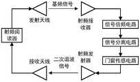
本发明解决上述技术问题所采用的技术方案为:一种无源RFID门窗传感器,包括射频接收器、信号倍频电路、信号分离电路、门窗传感电路和射频发射器,所述的射频接收器和所述的信号倍频电路连接,所述的信号倍频电路与所述的信号分离电路连接,所述的信号分离电路和所述的门窗传感电路连接,所述的门窗传感电路和所述的射频发射器连接,所述的射频接收器用于接入射频驱动信号并将射频驱动信号传递至所述的信号倍频电路处,所述的射频驱动信号为基频信号,所述的射频驱动信号由射频阅读器经由发射天线发出,所述的射频发射器用于发射谐波射频驱动信号,所述的谐波射频驱动信号为二次谐波信号,所述的门窗传感电路包括磁感应开关、磁铁、二次谐波滤波器和发射器匹配电路,所述的二次谐波滤波器用于连接所述的信号分离电路,所述的二次谐波滤波器分别与所述的发射器匹配电路和所述的磁感应开关的一端连接,所述的磁感应开关的另一端接地,所述的发射器匹配电路用于连接所述的射频发射器,所述的磁感应开关安装在门上或窗户上,所述的磁铁安装在门框或窗框上,所述的发射器匹配电路用于实现所述的门窗传感电路与所述的射频发射器之间的阻抗匹配,保证信号最大功率传输,所述的二次谐波滤波器用于对输入其内的二次谐波信号进行滤波处理,得到谐波射频驱动信号输出;当所述的射频接收器接入射频阅读器经由发射天线发出的射频驱动信号时,所述的射频接收器将所述的射频驱动信号传递给所述的信号倍频电路,所述的信号倍频电路对所述的射频驱动信号进行倍频处理后得到直流信号和二次谐波信号的混合信号输出至所述的信号分离电路,所述的信号分离电路对所述的混合信号进行分离,将所述的混合信号的二次谐波信号分离出来并输出至所述的门窗传感电路,所述的二次谐波滤波器对输入其内的二次谐波信号进行滤波处理,得到谐波射频驱动信号输出,如果此时门或窗户关闭,门或窗户靠近门框或窗框,所述的磁铁也靠近所述的磁感应开关,所述的磁感应开关在所述的磁铁作用下为闭合状态,所述的二次谐波滤波器经所述的磁感应开关连接到地,所述的二次谐波滤波器输出的谐波射频驱动信号传输到地,能够有效被过滤,不能输出至所述的发射器匹配电路后经由所述的发射器匹配电路传输到所述的射频发射器中,所述的射频发射器无法辐射谐波射频驱动信号到自由空间,此时射频阅读器接收不到谐波射频驱动信号,射频阅读器即可判定门窗处于关闭状态,如果此时门或窗户开启,门或窗户远离门框或窗框,所述的磁铁也远离所述的磁感应开关,所述的磁铁对所述的磁感应开关的作用力不足以保持所述的磁感应开关为闭合状态,所述的磁感应开关为断开状态,所述的二次谐波滤波器输出的谐波射频驱动信号无法经由地有效过滤掉,该谐波射频驱动信号输出至所述的发射器匹配电路后经由所述的发射器匹配电路传输到所述的射频发射器中,所述的射频发射器将谐波射频驱动信号辐射到自由空间,此时射频阅读器能够接收到谐波射频驱动信号,射频阅读器即可判定门窗被意外开启。The technical solution adopted by the present invention to solve the above technical problems is: a passive RFID door and window sensor, comprising a radio frequency receiver, a signal frequency multiplier circuit, a signal separation circuit, a door and window sensing circuit and a radio frequency transmitter, the radio frequency receiver It is connected with the signal frequency doubling circuit, the signal frequency doubling circuit is connected with the signal separation circuit, the signal separation circuit is connected with the door and window sensing circuit, and the door and window sensing circuit is connected to the door and window sensing circuit. The radio frequency transmitter is connected, the radio frequency receiver is used to access the radio frequency drive signal and transmit the radio frequency drive signal to the signal frequency multiplier circuit, the radio frequency drive signal is the fundamental frequency signal, the The radio frequency drive signal is sent by the radio frequency reader via the transmitting antenna, the radio frequency transmitter is used to transmit the harmonic radio frequency drive signal, the harmonic radio frequency drive signal is the second harmonic signal, and the door and window sensing circuit includes magnetic induction. a switch, a magnet, a second harmonic filter and a transmitter matching circuit, the second harmonic filter is used to connect the signal separation circuit, and the second harmonic filter is respectively connected with the transmitter The matching circuit is connected to one end of the magnetic induction switch, the other end of the magnetic induction switch is grounded, the transmitter matching circuit is used to connect the radio frequency transmitter, and the magnetic induction switch is installed on the door or window On the above, the magnet is installed on the door frame or the window frame, and the transmitter matching circuit is used to realize the impedance matching between the door and window sensing circuit and the radio frequency transmitter, so as to ensure the maximum power transmission of the signal, The second harmonic filter is used to filter the input second harmonic signal to obtain the harmonic radio frequency drive signal output; when the radio frequency receiver is connected to the radio frequency reader, the radio frequency emitted by the transmitting antenna is When driving a signal, the radio frequency receiver transmits the radio frequency drive signal to the signal frequency multiplier circuit, and the signal frequency multiplier circuit performs frequency multiplication processing on the radio frequency drive signal to obtain a DC signal and a frequency multiplier. The mixed signal of the second harmonic signal is output to the signal separation circuit, and the signal separation circuit separates the mixed signal, separates the second harmonic signal of the mixed signal and outputs it to the In the door and window sensing circuit described above, the second harmonic filter performs filtering processing on the input second harmonic signal to obtain the harmonic radio frequency drive signal output. If the door or window is closed at this time, the door or window is close to Door frame or window frame, the magnet is also close to the magnetic induction switch, the magnetic induction switch is in a closed state under the action of the magnet, and the second harmonic filter is connected to the magnetic induction switch through the magnetic induction switch. ground, the harmonic RF drive signal output by the second harmonic filter is transmitted to the ground, can be effectively filtered, and cannot be output to the transmitter matching circuit and then transmitted to the transmitter matching circuit through the transmitter matching circuit. In the RF transmitter, the RF transmitter cannot radiate the harmonic RF drive signal to the free space. At this time, the RF reader cannot receive the harmonic RF drive signal, and the RF reader can determine that the doors and windows are closed. If this When the door or window is open, the door or window is far away Door frame or window frame, the magnet is also far away from the magnetic induction switch, the force of the magnet on the magnetic induction switch is not enough to keep the magnetic induction switch closed, and the magnetic induction switch is open state, the harmonic RF drive signal output by the second harmonic filter cannot be effectively filtered out through the ground, and the harmonic RF drive signal is output to the transmitter matching circuit and then transmitted through the transmitter matching circuit In the radio frequency transmitter, the radio frequency transmitter radiates the harmonic radio frequency drive signal to the free space. At this time, the radio frequency reader can receive the harmonic radio frequency drive signal, and the radio frequency reader can determine that the doors and windows are accidentally opened. .
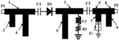
所述的信号倍频电路包括第一微带线、第二微带线、第三微带线、第四微带线、第五微带线、第一电容和肖特基二极管;所述的第一微带线和所述的第二微带线分别沿从左向右方向横向设置,所述的第一微带线位于所述的第二微带线的左侧,所述的第一微带线沿左右方向的中线所在直线与所述的第二微带线沿左右方向的中线所在直线重合,所述的第三微带线和所述的第四微带线分别沿从前往后方向纵向设置,所述的第三微带线和所述的第四微带线按照从左往右的顺序间隔分布;所述的第一微带线沿左右方向的长度为22.7mm,所述的第一微带线沿前后方向的长度为3mm,所述的第二微带线沿左右方向的长度为15mm,所述的第二微带线沿前后方向的长度为3mm,所述的第三微带线沿左右方向的长度为3mm,所述的第三微带线沿前后方向的长度为8.4mm,所述的第四微带线沿左右方向的长度为3mm,所述的第四微带线沿前后方向的长度为8.5mm,所述的第五微带线沿左右方向的长度为3mm,所述的第五微带线沿前后方向的长度为17.5mm,所述的第一微带线的左端通过第一SMA母头同轴连接器与所述的射频接收器的输出端连接,所述的信号倍频电路通过所述的第一微带线接入所述的射频接收器输出的射频驱动信号,所述的第三微带线和所述的第四微带线位于所述的第一微带线的后侧,所述的第三微带线的前端和所述的第四微带线的前端分别与所述的第一微带线的后端连接,所述的第一微带线的左端所在平面位于所述的第三微带线的左端所在平面的右侧,且两者之间的距离为4mm,所述的第三微带线的右端所在平面位于所述的第四微带线的左端所在平面的左侧,且两者之间的距离为8.7mm,所述的第五微带线位于所述的第二微带线的后侧,所述的第五微带线的前端与所述的第二微带线的后端连接,所述的第五微带线的左端所在平面位于所述的第二微带线的左端所在平面的右侧,且两者之间的距离为4mm,所述的第一电容和所述的肖特基二极管设置在所述的第一微带线和所述的第二微带线之间,所述的第一电容的一端和所述的第一微带线的右端连接,所述的第一电容的另一端和所述的肖特基极管的正极连接,所述的肖特基二极管的负极和所述的第二微带线的左端连接,所述的第二微带线用于连接所述的信号分离电路。该信号倍频电路中,第三微带线构成了接收器匹配电路,第四微带线构成了二次谐波滤波器,第五微带线构成了基频滤波器,当射频驱动信号传递到信号倍频电路,接收器匹配电路实现与射频接收器之间的阻抗匹配,保证射频驱动信号的最大功率传输,二次谐波滤波器滤去射频驱动信号中的二次谐波信号,射频驱动信号经过第一电容和肖特基二极管传递到基频滤波器,基频滤波器过滤掉射频驱动信号中的基频信号,由此该信号倍频电路能够对射频驱动信号进行精确的倍频处理后得到直流信号和二次谐波信号的混合信号,同时采用微带线结构设计,结构简单,易于加工,面积较小。The signal frequency multiplier circuit includes a first microstrip line, a second microstrip line, a third microstrip line, a fourth microstrip line, a fifth microstrip line, a first capacitor and a Schottky diode; the described The first microstrip line and the second microstrip line are respectively arranged laterally from left to right, the first microstrip line is located on the left side of the second microstrip line, and the first microstrip line is located on the left side of the second microstrip line The line where the center line of the microstrip line is located in the left and right directions coincides with the line where the center line of the second microstrip line is located in the left and right direction, and the third microstrip line and the fourth microstrip line are respectively along the front and back. The third microstrip line and the fourth microstrip line are distributed at intervals from left to right; the length of the first microstrip line along the left and right direction is 22.7mm, and the The length of the first microstrip line in the front-rear direction is 3mm, the length of the second microstrip line in the left-right direction is 15mm, the length of the second microstrip line in the front-rear direction is 3mm, and the length of the second microstrip line in the front-rear direction is 3mm. The length of the three microstrip lines in the left and right directions is 3 mm, the length of the third microstrip line in the front and rear directions is 8.4 mm, the length of the fourth microstrip line in the left and right directions is 3 mm, and the length of the fourth microstrip line in the left and right directions is 3 mm. The length of the microstrip line in the front-rear direction is 8.5 mm, the length of the fifth microstrip line in the left-right direction is 3 mm, the length of the fifth microstrip line in the front-rear direction is 17.5 mm, and the first microstrip line is 17.5 mm in length. The left end of the microstrip line is connected to the output end of the radio frequency receiver through the first SMA female coaxial connector, and the signal frequency multiplier circuit is connected to the radio frequency receiver through the first microstrip line the RF drive signal output by the device, the third microstrip line and the fourth microstrip line are located at the back side of the first microstrip line, the front end of the third microstrip line and the The front end of the fourth microstrip line is respectively connected with the rear end of the first microstrip line, and the plane where the left end of the first microstrip line is located is located to the right of the plane where the left end of the third microstrip line is located. side, and the distance between the two is 4mm, the plane where the right end of the third microstrip line is located is located on the left side of the plane where the left end of the fourth microstrip line is located, and the distance between the two is 8.7 mm, the fifth microstrip line is located at the rear side of the second microstrip line, the front end of the fifth microstrip line is connected to the rear end of the second microstrip line, and the The plane where the left end of the fifth microstrip line is located is located on the right side of the plane where the left end of the second microstrip line is located, and the distance between the two is 4mm, the first capacitor and the Schottky diode. It is arranged between the first microstrip line and the second microstrip line, one end of the first capacitor is connected to the right end of the first microstrip line, and the The other end is connected to the anode of the Schottky diode, the cathode of the Schottky diode is connected to the left end of the second microstrip line, and the second microstrip line is used to connect the signal separation circuit. In the signal frequency multiplication circuit, the third microstrip line constitutes the receiver matching circuit, the fourth microstrip line constitutes the second harmonic filter, and the fifth microstrip line constitutes the fundamental frequency filter. To the signal frequency multiplier circuit, the receiver matching circuit realizes impedance matching with the RF receiver to ensure the maximum power transmission of the RF drive signal, and the second harmonic filter filters out the second harmonic signal in the RF drive signal. The driving signal is transmitted to the fundamental frequency filter through the first capacitor and the Schottky diode, and the fundamental frequency filter filters out the fundamental frequency signal in the RF driving signal, so that the signal frequency multiplier circuit can accurately multiply the frequency of the RF driving signal After processing, the mixed signal of the DC signal and the second harmonic signal is obtained, and the microstrip line structure design is adopted at the same time, the structure is simple, the processing is easy, and the area is small.
所述的信号分离电路包括电感、电阻和第二电容,所述的电感和所述的电阻均位于所述的第二微带线的后侧以及所述的第五微带线的右侧,所述的电感位于所述的电阻的前侧,所述的电感的一端和所述的第二微带线的后端连接,所说的电感的另一端和所述的电阻的一端连接,所述的电阻的另一端接地,所述的第二电容的一端与所述的第二微带线的右端连接,所述的第二电容的另一端用于连接所述的门窗传感电路。该信号分离电路中,二次谐波信号无法经过电感,直流信号无法经过电容,直流信号经过电感和电阻后接地,可减少直流信号对二次谐波信号的干扰,从而实现了直流信号和二次谐波信号的精确分离。The signal separation circuit includes an inductor, a resistor and a second capacitor, and the inductor and the resistor are located on the rear side of the second microstrip line and on the right side of the fifth microstrip line, The inductor is located on the front side of the resistor, one end of the inductor is connected to the rear end of the second microstrip line, and the other end of the inductor is connected to one end of the resistor, so The other end of the resistor is grounded, one end of the second capacitor is connected to the right end of the second microstrip line, and the other end of the second capacitor is used to connect to the door and window sensing circuit. In this signal separation circuit, the second harmonic signal cannot pass through the inductor, and the DC signal cannot pass through the capacitor. Precise separation of sub-harmonic signals.
所述的二次谐波滤波器包括第六微带线和第七微带线,所述的第六微带线位于所述的第二电容的右侧,所述的第六微带线沿左右方向横向设置,所述的第六微带线的左端和所述的第二电容的另一端连接,所述的第七微带线位于所述的第六微带线的后侧,所述的第七微带线沿前后方向纵向设置,所述的第六微带线的后端和所述的第七微带线的前端连接,所述的第七微带线的后端连接所述的磁感应开关的一端,所述的第七微带线的左端所在平面位于所述的第六微带线的左端所在平面的右侧,且两者之间的距离为4mm,所述的第六微带线沿左右方向的长度为7mm,所述的第六微带线沿前后方向的长度为3mm,所述的第七微带线沿前后方向的长度为15.9mm,所述的第七微带线沿左右方向的长度为3mm;所述的发射器匹配电路包括第八微带线和第九微带线,所述的第八微带线位于所述的第六微带线的右侧,所述的第八微带线沿左右方向横向设置,所述的第八微带线的左端和所述的第六微带线的右端连接,所述的第八微带线的右端通过第二SMA母头同轴连接器与所述的射频发射器连接,所述的第九微带线位于所述的第八微带线的后侧,所述的第九微带线沿前后方向纵向设置,所述的第八微带线的后端和所述的第九微带线的前端连接,所述的第九微带线的左端所在平面位于所述的第八微带线的左端所在平面的右侧,且两者之间的距离为8.5mm,所述的第八微带线沿前后方向的长度为3mm,所述的第八微带线沿左右方向的长度为15.5mm,所述的第九微带线沿前后方向的长度为3.5mm,所述的第九微带线沿左右方向的长度为3mm。该结构中,如果门或窗户关闭,门或窗户靠近门框或窗框,磁铁也靠近磁感应开关,磁感应开关在磁铁作用下为闭合状态,二次谐波滤波器经磁感应开关连接到地,二次谐波滤波器输出的谐波射频驱动信号传输到地,能够有效被过滤,不能输出至发射器匹配电路,如果此时门或窗户开启,门或窗户远离门框或窗框,磁铁也远离磁感应开关,磁感应开关为断开状态,二次谐波滤波器输出的谐波射频驱动信号无法经由地有效过滤掉,该谐波射频驱动信号输出至发射器匹配电路,发射器匹配电路实现与射频发射器之间的阻抗匹配,保证谐波射频驱动信号的最大功率传输。The second harmonic filter includes a sixth microstrip line and a seventh microstrip line, the sixth microstrip line is located on the right side of the second capacitor, and the sixth microstrip line is along the The left and right directions are laterally arranged, the left end of the sixth microstrip line is connected to the other end of the second capacitor, the seventh microstrip line is located at the rear side of the sixth microstrip line, the The seventh microstrip line is longitudinally arranged in the front-rear direction, the rear end of the sixth microstrip line is connected with the front end of the seventh microstrip line, and the rear end of the seventh microstrip line is connected to the One end of the magnetic induction switch, the plane where the left end of the seventh microstrip line is located is located on the right side of the plane where the left end of the sixth microstrip line is located, and the distance between the two is 4mm, and the sixth microstrip line is located on the right side of the plane. The length of the microstrip line in the left-right direction is 7 mm, the length of the sixth microstrip line in the front-rear direction is 3 mm, the length of the seventh microstrip line in the front-rear direction is 15.9 mm, and the length of the seventh microstrip line in the front-rear direction is 15.9 mm. The length of the strip line along the left and right direction is 3mm; the transmitter matching circuit includes an eighth microstrip line and a ninth microstrip line, and the eighth microstrip line is located on the right side of the sixth microstrip line , the eighth microstrip line is laterally arranged along the left-right direction, the left end of the eighth microstrip line is connected with the right end of the sixth microstrip line, and the right end of the eighth microstrip line passes through the Two SMA female coaxial connectors are connected to the radio frequency transmitter, the ninth microstrip line is located at the rear side of the eighth microstrip line, and the ninth microstrip line is longitudinally along the front-rear direction Set, the rear end of the described eighth microstrip line is connected with the front end of the described ninth microstrip line, and the plane where the left end of the ninth microstrip line is located is located at the left end of the eighth microstrip line. The right side of the plane, and the distance between the two is 8.5mm, the length of the eighth microstrip line along the front-rear direction is 3mm, and the length of the eighth microstrip line along the left-right direction is 15.5mm, so The length of the ninth microstrip line in the front-rear direction is 3.5 mm, and the length of the ninth microstrip line in the left-right direction is 3 mm. In this structure, if the door or window is closed, the door or window is close to the door frame or window frame, the magnet is also close to the magnetic induction switch, the magnetic induction switch is closed under the action of the magnet, the second harmonic filter is connected to the ground through the magnetic induction switch, and the second harmonic filter is connected to the ground through the magnetic induction switch. The harmonic RF drive signal output by the harmonic filter is transmitted to the ground, which can be effectively filtered and cannot be output to the transmitter matching circuit. If the door or window is opened at this time, the door or window is far away from the door frame or window frame, and the magnet is also far away from the magnetic induction switch. , the magnetic induction switch is in the off state, the harmonic RF drive signal output by the second harmonic filter cannot be effectively filtered by the ground, the harmonic RF drive signal is output to the transmitter matching circuit, and the transmitter matching circuit realizes the connection with the RF transmitter. The impedance matching between them ensures the maximum power transmission of the harmonic RF drive signal.
所述的射频接收器、所述的信号倍频电路、所述的信号分离电路、所述的射频发射器以及所述的门窗传感电路中除磁铁以外的其他部分分别设置在一个电路板基板上,所述的电路板基板的材料为FR_4,所述电路板基板的厚度为1.5mm。The radio frequency receiver, the signal frequency multiplier circuit, the signal separation circuit, the radio frequency transmitter, and the other parts of the door and window sensing circuit except the magnet are respectively arranged on a circuit board substrate Above, the material of the circuit board substrate is FR_4, and the thickness of the circuit board substrate is 1.5mm.
所述的射频接收器和所述的射频发射器分别采用矩形微带贴片天线来实现,且所述的矩形微带贴片天线的馈电方式为微带线侧馈馈电方式。The radio frequency receiver and the radio frequency transmitter are respectively implemented by a rectangular microstrip patch antenna, and the feeding mode of the rectangular microstrip patch antenna is a microstrip line side feeding mode.
所述的射频接收器包括第一矩形金属块、第十微带线和第十一微带线,所述的第十微带线和所述的第十一微带线均沿从前向后方向纵向设置,所述的第一矩形金属块位于所述的第十微带线的前侧,所述的第十一微带线位于所述的第十微带线的后侧,所述的第一矩形金属块的后端与所述的第十微带线的前端连接,所述的第十微带线的后端与所述的第十一微带线的前端连接,所述的第一矩形金属片沿前后方向的中线所在直线、所述的第十微带线沿前后方向的中线所在直线以及所述的第十一微带线沿前后方向的中线所在直线重合,所述的第一矩形金属片沿前后方向的长度为28.1mm,所述的第一矩形金属片沿左右方向的长度为37.3mm,所述的第十微带线沿前后方向的长度为17.4mm,所述的第十微带线沿左右方向的长度为1mm,所述的第十一微带线沿前后方向的长度为15mm,所述的第十一微带线沿左右方向的长度为3mm,所述的第十一微带线的后端用于连接所述的第一SMA母头同轴连接器;所述的射频发射器包括第二矩形金属块、第十二微带线和第十三微带线,所述的第十二微带线和所述的第十三微带线均按照从前向后方向纵向设置,所述的第二矩形金属块位于所述的第十二微带线的前侧,所述的第十三微带线位于所述的第十二微带线的后侧,所述的第二矩形金属块后端与所述的第十二微带线的前端连接,所述的第十二微带线的后端与所述的第十三微带线的前端连接,所述的第十三微带线的后端用于与所述的第二SMA母头同轴连接器连接,所述的第二矩形金属片沿前后方向的中线所在直线、所述的第十二微带线沿前后方向的中线所在直线以及所述的第十三微带线沿前后方向的中线所在直线重合,所述的第二矩形金属片沿前后方向的长度为14.3mm,所述的第二矩形金属片沿左右方向的长度为18.8mm,所述的第十二微带线沿前后方向的长度为8.7mm,所述的第十二微带线沿左右方向的长度为1.2mm,所述的第十三微带线沿前后方向的长度为10mm,所述的第十三微带线沿左右方向的长度为3mm。The radio frequency receiver includes a first rectangular metal block, a tenth microstrip line and an eleventh microstrip line, and the tenth microstrip line and the eleventh microstrip line are in the direction from front to back. vertical arrangement, the first rectangular metal block is located on the front side of the tenth microstrip line, the eleventh microstrip line is located on the back side of the tenth microstrip line, the The rear end of a rectangular metal block is connected to the front end of the tenth microstrip line, the rear end of the tenth microstrip line is connected to the front end of the eleventh microstrip line, and the first The straight line where the center line of the rectangular metal sheet is located in the front-rear direction, the line where the center line of the tenth microstrip line is located along the front-rear direction, and the line where the center line of the eleventh microstrip line is located in the front-rear direction overlap, the first The length of the rectangular metal sheet in the front-rear direction is 28.1 mm, the length of the first rectangular metal sheet in the left-right direction is 37.3 mm, the length of the tenth microstrip line in the front-rear direction is 17.4 mm, and the first rectangular metal sheet is 17.4 mm in length. The length of the ten microstrip lines along the left and right directions is 1 mm, the length of the eleventh microstrip line along the front and rear directions is 15 mm, the length of the eleventh microstrip line along the left and right directions is 3 mm, and the length of the eleventh microstrip line along the left and right directions is 3 mm. The rear end of the eleventh microstrip line is used to connect the first SMA female coaxial connector; the radio frequency transmitter includes a second rectangular metal block, a twelfth microstrip line and a thirteenth microstrip line , the twelfth microstrip line and the thirteenth microstrip line are arranged longitudinally from front to back, and the second rectangular metal block is located on the front side of the twelfth microstrip line , the thirteenth microstrip line is located on the rear side of the twelfth microstrip line, the rear end of the second rectangular metal block is connected to the front end of the twelfth microstrip line, and the The rear end of the twelfth microstrip line is connected with the front end of the thirteenth microstrip line, and the rear end of the thirteenth microstrip line is used for coaxial connection with the second SMA female header The line where the center line of the second rectangular metal sheet is located in the front-rear direction, the line where the center line of the twelfth microstrip line is located in the front-rear direction, and the center line of the thirteenth microstrip line in the front-rear direction The lines where the lines overlap, the length of the second rectangular metal sheet in the front-rear direction is 14.3 mm, the length of the second rectangular metal sheet in the left-right direction is 18.8 mm, and the twelfth microstrip line is in the front-rear direction. The length of the microstrip line is 8.7mm, the length of the twelfth microstrip line along the left and right direction is 1.2mm, the length of the thirteenth microstrip line along the front and rear direction is 10mm, and the length of the thirteenth microstrip line is 10mm. The length in the left-right direction is 3 mm.
与现有技术相比,本发明的优点在于通过射频接收器、信号倍频电路、信号分离电路、门窗传感电路和射频发射器构成无源RFID门窗传感器,射频接收器和信号倍频电路连接,信号倍频电路与信号分离电路连接,信号分离电路和门窗传感电路连接,门窗传感电路和射频发射器连接,射频接收器用于接入射频驱动信号并将射频驱动信号传递至信号倍频电路处,射频驱动信号为基频信号,射频驱动信号由射频阅读器经由发射天线发出,射频发射器用于发射谐波射频驱动信号,谐波射频驱动信号为二次谐波信号,门窗传感电路包括磁感应开关、磁铁、二次谐波滤波器和发射器匹配电路,二次谐波滤波器用于连接信号分离电路,二次谐波滤波器分别与发射器匹配电路和磁感应开关的一端连接,磁感应开关的另一端接地,发射器匹配电路用于连接射频发射器,磁感应开关安装在门上或窗户上,磁铁安装在门框或窗框上,发射器匹配电路用于实现门窗传感电路与射频发射器之间的阻抗匹配,保证信号最大功率传输,二次谐波滤波器用于对输入其内的二次谐波信号进行滤波处理,得到谐波射频驱动信号输出;当射频接收器接入射频阅读器经由发射天线发出的射频驱动信号时,射频接收器将射频驱动信号传递给信号倍频电路,信号倍频电路对射频驱动信号进行倍频处理后得到直流信号和二次谐波信号的混合信号输出至信号分离电路,信号分离电路对混合信号进行分离,将混合信号的二次谐波信号分离出来并输出至门窗传感电路,二次谐波滤波器对输入其内的二次谐波信号进行滤波处理,得到谐波射频驱动信号输出,如果此时门或窗户关闭,门或窗户靠近门框或窗框,磁铁也靠近磁感应开关,磁感应开关在磁铁作用下为闭合状态,二次谐波滤波器经磁感应开关连接到地,二次谐波滤波器输出的谐波射频驱动信号传输到地,能够有效被过滤,不能输出至发射器匹配电路后经由发射器匹配电路传输到射频发射器中,射频发射器无法辐射谐波射频驱动信号到自由空间,此时射频阅读器接收不到谐波射频驱动信号,射频阅读器即可判定门窗处于关闭状态,如果此时门或窗户开启,门或窗户远离门框或窗框,磁铁也远离磁感应开关,磁铁对磁感应开关的作用力不足以保持磁感应开关为闭合状态,磁感应开关为断开状态,二次谐波滤波器输出的谐波射频驱动信号无法经由地有效过滤掉,该谐波射频驱动信号输出至发射器匹配电路后经由发射器匹配电路传输到射频发射器中,射频发射器将谐波射频驱动信号辐射到自由空间,此时射频阅读器能够接收到谐波射频驱动信号,射频阅读器即可判定门窗被意外开启,由此本发明可以在安装门窗上对门窗的关闭和开启状态进行监测,本发明的无源RFID门窗传感器不需要复杂的电子线路来实现供电和通讯,不需要额外的电池供电,且门窗传感器体积小,能运用在狭小的密闭空间内,本发明的电路结构能够主要基于微带线构成,其结构简单,易于加工,面积较小,可使用喷墨打印技术直接印刷或传统的电路板加工技术加工,大大降低了生产成本,且通过射频阅读器与其进行信息交互,灵敏度较高,不易出现误判,判断准确度高。Compared with the prior art, the present invention has the advantage that a passive RFID door and window sensor is formed by a radio frequency receiver, a signal frequency multiplier circuit, a signal separation circuit, a door and window sensing circuit and a radio frequency transmitter, and the radio frequency receiver is connected with the signal frequency multiplier circuit. , the signal frequency multiplier circuit is connected with the signal separation circuit, the signal separation circuit is connected with the door and window sensing circuit, the door and window sensor circuit is connected with the radio frequency transmitter, and the radio frequency receiver is used to access the radio frequency drive signal and transmit the radio frequency drive signal to the signal frequency doubler At the circuit, the RF driving signal is the fundamental frequency signal, the RF driving signal is sent by the RF reader through the transmitting antenna, the RF transmitter is used to transmit the harmonic RF driving signal, the harmonic RF driving signal is the second harmonic signal, and the door and window sensing circuit It includes a magnetic induction switch, a magnet, a second harmonic filter and a transmitter matching circuit. The second harmonic filter is used to connect the signal separation circuit. The second harmonic filter is respectively connected with the transmitter matching circuit and one end of the magnetic induction switch. The magnetic induction The other end of the switch is grounded, the transmitter matching circuit is used to connect the RF transmitter, the magnetic induction switch is installed on the door or window, the magnet is installed on the door frame or window frame, and the transmitter matching circuit is used to realize the door and window sensing circuit and RF transmission. The impedance matching between the receivers ensures the maximum power transmission of the signal. The second harmonic filter is used to filter the input second harmonic signal to obtain the harmonic RF drive signal output; when the RF receiver is connected to the RF reading When the receiver sends the RF drive signal through the transmitting antenna, the RF receiver transmits the RF drive signal to the signal frequency multiplier circuit, and the signal frequency multiplier circuit multiplies the RF drive signal to obtain a mixed signal of the DC signal and the second harmonic signal. Output to the signal separation circuit, the signal separation circuit separates the mixed signal, separates the second harmonic signal of the mixed signal and outputs it to the door and window sensing circuit, and the second harmonic filter is used to input the second harmonic signal in it. Filter processing to obtain harmonic RF drive signal output. If the door or window is closed at this time, the door or window is close to the door frame or window frame, and the magnet is also close to the magnetic induction switch, the magnetic induction switch is closed under the action of the magnet, and the second harmonic filter The transmitter is connected to the ground through the magnetic induction switch, and the harmonic RF drive signal output by the second harmonic filter is transmitted to the ground, which can be effectively filtered, but cannot be output to the transmitter matching circuit and then transmitted to the RF transmitter through the transmitter matching circuit. The RF transmitter cannot radiate the harmonic RF drive signal to the free space. At this time, the RF reader cannot receive the harmonic RF drive signal, and the RF reader can determine that the door and window are closed. If the door or window is open at this time, the door or window Keep away from the door frame or window frame, and the magnet is also away from the magnetic induction switch. The force of the magnet on the magnetic induction switch is not enough to keep the magnetic induction switch in the closed state and the magnetic induction switch in the open state. The harmonic RF drive signal output by the second harmonic filter cannot pass through. The harmonic RF drive signal is effectively filtered out, and the harmonic RF drive signal is output to the transmitter matching circuit and then transmitted to the RF transmitter through the transmitter matching circuit. The RF transmitter radiates the harmonic RF drive signal into free space. At this time, the RF reader can Harmonic RF received Drive signal, the radio frequency reader can determine that the doors and windows are accidentally opened, so the present invention can monitor the closing and opening states of the doors and windows on the installed doors and windows, and the passive RFID door and window sensor of the present invention does not require complex electronic circuits to realize power supply and communication, no additional battery power supply is required, and the door and window sensor is small in size and can be used in a narrow confined space. Using inkjet printing technology for direct printing or traditional circuit board processing technology greatly reduces the production cost, and through the radio frequency reader for information interaction with it, the sensitivity is high, misjudgment is not easy to occur, and the judgment accuracy is high.
附图说明Description of drawings
图1为本发明的无源RFID门窗传感器与射频阅读器的结构原理框图;Fig. 1 is the structural principle block diagram of passive RFID door and window sensor and radio frequency reader of the present invention;
图2为本发明的无源RFID门窗传感器的信号倍频电路、信号分离电路和门窗传感电路的电路图;2 is a circuit diagram of a signal frequency multiplier circuit, a signal separation circuit and a door and window sensing circuit of the passive RFID door and window sensor of the present invention;
图3(a)为本发明的无源RFID门禁传感器的磁感应开关处于闭合状态的示意图;Fig. 3 (a) is the schematic diagram that the magnetic induction switch of the passive RFID access control sensor of the present invention is in the closed state;
图3(b)为本发明的无源RFID门禁传感器的磁感应处于断开状态的示意图;Fig. 3 (b) is the schematic diagram that the magnetic induction of the passive RFID access control sensor of the present invention is in the disconnected state;
图4为本发明的无源RFID门窗传感器的射频接收器的结构图;Fig. 4 is the structure diagram of the radio frequency receiver of the passive RFID door and window sensor of the present invention;
图5为本发明的无源RFID门窗传感器的射频发射器的结构图;Fig. 5 is the structure diagram of the radio frequency transmitter of the passive RFID door and window sensor of the present invention;
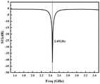
图6为本发明的无源RFID门窗传感器的射频接收器的S11参数随工作频率变化的仿真波形图;6 is a simulation waveform diagram of the S11 parameter of the radio frequency receiver of the passive RFID door and window sensor of the present invention varying with the operating frequency;
图7为本发明的无源RFID门窗传感器的射频发射器的S11参数随工作频率变化的仿真波形图;7 is a simulation waveform diagram of the S11 parameter of the radio frequency transmitter of the passive RFID door and window sensor of the present invention varying with the operating frequency;
图8为本发明的无源RFID门窗传感器的S(2,1)参数随工作频率变化的仿真波形图;8 is a simulation waveform diagram of the S(2,1) parameter of the passive RFID door and window sensor of the present invention changing with the operating frequency;
图9为本发明的无源RFID门窗传感器的输出二次谐波功率随输入的基频信号功率变化的仿真波形图。FIG. 9 is a simulation waveform diagram of the output second harmonic power of the passive RFID door and window sensor of the present invention changing with the input fundamental frequency signal power.
具体实施方式Detailed ways
以下结合附图实施例对本发明作进一步详细描述。The present invention will be further described in detail below with reference to the embodiments of the accompanying drawings.
实施例:如图1、图2、图3(a)和图3(b)所示,一种无源RFID门窗传感器,包括射频接收器、信号倍频电路、信号分离电路、门窗传感电路和射频发射器,射频接收器和信号倍频电路连接,信号倍频电路与信号分离电路连接,信号分离电路和门窗传感电路连接,门窗传感电路和射频发射器连接,射频接收器用于接入射频驱动信号并将射频驱动信号传递至信号倍频电路处,射频驱动信号为基频信号,射频驱动信号由射频阅读器经由发射天线发出,射频发射器用于发射谐波射频驱动信号,谐波射频驱动信号为二次谐波信号,门窗传感电路包括磁感应开关K1、磁铁T1、二次谐波滤波器和发射器匹配电路,二次谐波滤波器用于连接信号分离电路,二次谐波滤波器分别与发射器匹配电路和磁感应开关K1的一端连接,磁感应开关K1的另一端接地,发射器匹配电路用于连接射频发射器,磁感应开关K1安装在门上或窗户上,磁铁T1安装在门框或窗框上,发射器匹配电路用于实现门窗传感电路与射频发射器之间的阻抗匹配,保证信号最大功率传输,二次谐波滤波器用于对输入其内的二次谐波信号进行滤波处理,得到谐波射频驱动信号输出;当射频接收器接入射频阅读器经由发射天线发出的射频驱动信号时,射频接收器将射频驱动信号传递给信号倍频电路,信号倍频电路对射频驱动信号进行倍频处理后得到直流信号和二次谐波信号的混合信号输出至信号分离电路,信号分离电路对混合信号进行分离,将混合信号的二次谐波信号分离出来并输出至门窗传感电路,二次谐波滤波器对输入其内的二次谐波信号进行滤波处理,得到谐波射频驱动信号输出,如果此时门或窗户关闭,门或窗户靠近门框或窗框,磁铁T1也靠近磁感应开关K1,磁感应开关K1在磁铁T1作用下为闭合状态,二次谐波滤波器经磁感应开关K1连接到地,二次谐波滤波器输出的谐波射频驱动信号传输到地,能够有效被过滤,不能输出至发射器匹配电路后经由发射器匹配电路传输到射频发射器中,射频发射器无法辐射谐波射频驱动信号到自由空间,此时射频阅读器接收不到谐波射频驱动信号,射频阅读器即可判定门窗处于关闭状态,如果此时门或窗户开启,门或窗户远离门框或窗框,磁铁T1也远离磁感应开关K1,磁铁T1对磁感应开关K1的作用力不足以保持磁感应开关K1为闭合状态,磁感应开关K1为断开状态,二次谐波滤波器输出的谐波射频驱动信号无法经由地有效过滤掉,该谐波射频驱动信号输出至发射器匹配电路后经由发射器匹配电路传输到射频发射器中,射频发射器将谐波射频驱动信号辐射到自由空间,此时射频阅读器能够接收到谐波射频驱动信号,射频阅读器即可判定门窗被意外开启。Example: As shown in Figure 1, Figure 2, Figure 3(a) and Figure 3(b), a passive RFID door and window sensor includes a radio frequency receiver, a signal frequency multiplier circuit, a signal separation circuit, and a door and window sensing circuit It is connected with the radio frequency transmitter, the radio frequency receiver and the signal frequency multiplication circuit, the signal frequency multiplication circuit is connected with the signal separation circuit, the signal separation circuit is connected with the door and window sensing circuit, the door and window sensor circuit is connected with the radio frequency transmitter, and the radio frequency receiver is used for connecting Input the RF driving signal and transmit the RF driving signal to the signal frequency multiplier circuit, the RF driving signal is the fundamental frequency signal, the RF driving signal is sent by the RF reader through the transmitting antenna, and the RF transmitter is used to transmit the harmonic RF driving signal. The RF drive signal is a second harmonic signal. The door and window sensing circuit includes a magnetic induction switch K1, a magnet T1, a second harmonic filter and a transmitter matching circuit. The second harmonic filter is used to connect the signal separation circuit. The second harmonic The filter is respectively connected with the transmitter matching circuit and one end of the magnetic induction switch K1, the other end of the magnetic induction switch K1 is grounded, the transmitter matching circuit is used to connect the radio frequency transmitter, the magnetic induction switch K1 is installed on the door or window, and the magnet T1 is installed on the On the door frame or window frame, the transmitter matching circuit is used to realize the impedance matching between the door and window sensing circuit and the RF transmitter to ensure the maximum power transmission of the signal. The second harmonic filter is used to input the second harmonic signal into it. Perform filtering processing to obtain harmonic radio frequency drive signal output; when the radio frequency receiver is connected to the radio frequency drive signal sent by the radio frequency reader through the transmitting antenna, the radio frequency receiver transmits the radio frequency drive signal to the signal frequency multiplier circuit, and the signal frequency multiplier circuit is used for the signal frequency multiplication circuit. After the RF drive signal is frequency multiplied, the mixed signal of the DC signal and the second harmonic signal is output to the signal separation circuit. The signal separation circuit separates the mixed signal, separates the second harmonic signal of the mixed signal and outputs it to the doors and windows The sensing circuit, the second harmonic filter filters the input second harmonic signal, and obtains the harmonic radio frequency drive signal output. If the door or window is closed at this time, the door or window is close to the door frame or window frame, and the magnet T1 is also close to the magnetic induction switch K1, the magnetic induction switch K1 is closed under the action of the magnet T1, the second harmonic filter is connected to the ground through the magnetic induction switch K1, and the harmonic RF drive signal output by the second harmonic filter is transmitted to the ground, It can be effectively filtered and cannot be output to the transmitter matching circuit and then transmitted to the RF transmitter through the transmitter matching circuit. The RF transmitter cannot radiate the harmonic RF drive signal to the free space, and the RF reader cannot receive the harmonic RF. Drive the signal, the radio frequency reader can determine that the door and window are closed. If the door or window is open at this time, the door or window is far away from the door frame or window frame, and the magnet T1 is also far away from the magnetic induction switch K1. The force of the magnet T1 on the magnetic induction switch K1 is not enough. Keep the magnetic induction switch K1 in the closed state and the magnetic induction switch K1 in the open state, the harmonic RF driving signal output by the second harmonic filter cannot be effectively filtered out, and the harmonic RF driving signal is output to the transmitter matching circuit and then passes through The transmitter matching circuit transmits to the transmitter In the radio frequency transmitter, the radio frequency transmitter radiates the harmonic radio frequency drive signal into the free space. At this time, the radio frequency reader can receive the harmonic radio frequency drive signal, and the radio frequency reader can determine that the doors and windows are accidentally opened.
本实施例中,信号倍频电路包括第一微带线1、第二微带线2、第三微带线3、第四微带线4、第五微带线5、第一电容C1和肖特基二极管D1;第一微带线1和第二微带线2分别沿从左向右方向横向设置,第一微带线1位于第二微带线2的左侧,第一微带线1沿左右方向的中线所在直线与第二微带线2沿左右方向的中线所在直线重合,第三微带线3和第四微带线4分别沿从前往后方向纵向设置,第三微带线3和第四微带线4按照从左往右的顺序间隔分布;第一微带线1沿左右方向的长度为22.7mm,第一微带线1沿前后方向的长度为3mm,第二微带线2沿左右方向的长度为15mm,第二微带线2沿前后方向的长度为3mm,第三微带线3沿左右方向的长度为3mm,第三微带线3沿前后方向的长度为8.4mm,第四微带线4沿左右方向的长度为3mm,第四微带线4沿前后方向的长度为8.5mm,第五微带线5沿左右方向的长度为3mm,第五微带线5沿前后方向的长度为17.5mm,第一微带线1的左端通过第一SMA母头同轴连接器P1与射频接收器的输出端连接,信号倍频电路通过第一微带线1接入射频接收器输出的射频驱动信号,第三微带线3和第四微带线4位于第一微带线1的后侧,第三微带线3的前端和第四微带线4的前端分别与第一微带线1的后端连接,第一微带线1的左端所在平面位于第三微带线3的左端所在平面的右侧,且两者之间的距离为4mm,第三微带线3的右端所在平面位于第四微带线4的左端所在平面的左侧,且两者之间的距离为8.7mm,第五微带线5位于第二微带线2的后侧,第五微带线5的前端与第二微带线2的后端连接,第五微带线5的左端所在平面位于第二微带线2的左端所在平面的右侧,且两者之间的距离为4mm,第一电容C1和肖特基二极管D1设置在第一微带线1和第二微带线2之间,第一电容C1的一端和第一微带线1的右端连接,第一电容C1的另一端和肖特基极管的正极连接,肖特基二极管D1的负极和第二微带线2的左端连接,第二微带线2用于连接信号分离电路。In this embodiment, the signal frequency multiplier circuit includes a first microstrip line 1, a
本实施例中,信号分离电路包括电感L1、电阻R1和第二电容C2,电感L1和电阻R1均位于第二微带线2的后侧以及第五微带线5的右侧,电感L1位于电阻R1的前侧,电感L1的一端和第二微带线2的后端连接,所说的电感L1的另一端和电阻R1的一端连接,电阻R1的另一端接地,第二电容C2的一端与第二微带线2的右端连接,第二电容C2的另一端用于连接门窗传感电路。In this embodiment, the signal separation circuit includes an inductor L1, a resistor R1, and a second capacitor C2. Both the inductor L1 and the resistor R1 are located on the rear side of the
本实施例中,二次谐波滤波器包括第六微带线6和第七微带线7,第六微带线6位于第二电容C2的右侧,第六微带线6沿左右方向横向设置,第六微带线6的左端和第二电容C2的另一端连接,第七微带线7位于第六微带线6的后侧,第七微带线7沿前后方向纵向设置,第六微带线6的后端和第七微带线7的前端连接,第七微带线7的后端连接磁感应开关K1的一端,第七微带线7的左端所在平面位于第六微带线6的左端所在平面的右侧,且两者之间的距离为4mm,第六微带线6沿左右方向的长度为7mm,第六微带线6沿前后方向的长度为3mm,第七微带线7沿前后方向的长度为15.9mm,第七微带线7沿左右方向的长度为3mm;发射器匹配电路包括第八微带线8和第九微带线9,第八微带线8位于第六微带线6的右侧,第八微带线8沿左右方向横向设置,第八微带线8的左端和第六微带线6的右端连接,第八微带线8的右端通过第二SMA母头同轴连接器P2与射频发射器连接,第九微带线9位于第八微带线8的后侧,第九微带线9沿前后方向纵向设置,第八微带线8的后端和第九微带线9的前端连接,第九微带线9的左端所在平面位于第八微带线8的左端所在平面的右侧,且两者之间的距离为8.5mm,第八微带线8沿前后方向的长度为3mm,第八微带线8沿左右方向的长度为15.5mm,第九微带线9沿前后方向的长度为3.5mm,第九微带线9沿左右方向的长度为3mm。In this embodiment, the second harmonic filter includes a sixth microstrip line 6 and a seventh microstrip line 7, the sixth microstrip line 6 is located on the right side of the second capacitor C2, and the sixth microstrip line 6 is in the left-right direction Horizontal arrangement, the left end of the sixth microstrip line 6 is connected to the other end of the second capacitor C2, the seventh microstrip line 7 is located at the rear side of the sixth microstrip line 6, and the seventh microstrip line 7 is longitudinally arranged in the front-rear direction, The rear end of the sixth microstrip line 6 is connected to the front end of the seventh microstrip line 7, the rear end of the seventh microstrip line 7 is connected to one end of the magnetic induction switch K1, and the plane where the left end of the seventh microstrip line 7 is located is located in the sixth microstrip line. The left end of the strip line 6 is on the right side of the plane, and the distance between the two is 4 mm, the length of the sixth microstrip line 6 in the left-right direction is 7 mm, the length of the sixth microstrip line 6 in the front-rear direction is 3 mm, and the length of the sixth microstrip line 6 in the front-rear direction is 3 mm. The length of the seventh microstrip line 7 in the front-rear direction is 15.9 mm, and the length of the seventh microstrip line 7 in the left-right direction is 3 mm; the transmitter matching circuit includes the eighth microstrip line 8 and the
本实施例中,射频接收器、信号倍频电路、信号分离电路、射频发射器以及门窗传感电路中除磁铁T1以外的其他部分分别设置在一个电路板基板上,电路板基板的材料为FR_4,所述电路板基板的厚度为1.5mm。In this embodiment, the radio frequency receiver, the signal frequency multiplier circuit, the signal separation circuit, the radio frequency transmitter and other parts except the magnet T1 in the door and window sensing circuit are respectively arranged on a circuit board substrate, and the material of the circuit board substrate is FR_4 , the thickness of the circuit board substrate is 1.5mm.
本实施例中,射频接收器和射频发射器分别采用矩形微带贴片天线来实现,且矩形微带贴片天线的馈电方式为微带线侧馈馈电方式。如图4和图5所示,射频接收器包括第一矩形金属块10、第十微带线11和第十一微带线12,第十微带线11和第十一微带线12均沿从前向后方向纵向设置,第一矩形金属块10位于第十微带线11的前侧,第十一微带线12位于第十微带线11的后侧,第一矩形金属块10的后端与第十微带线11的前端连接,第十微带线11的后端与第十一微带线12的前端连接,第一矩形金属片沿前后方向的中线所在直线、第十微带线11沿前后方向的中线所在直线以及第十一微带线12沿前后方向的中线所在直线重合,第一矩形金属片沿前后方向的长度为28.1mm,第一矩形金属片沿左右方向的长度为37.3mm,第十微带线11沿前后方向的长度为17.4mm,第十微带线11沿左右方向的长度为1mm,第十一微带线12沿前后方向的长度为15mm,第十一微带线12沿左右方向的长度为3mm,第十一微带线12的后端用于连接第一SMA母头同轴连接器P1;射频发射器包括第二矩形金属块13、第十二微带线14和第十三微带线15,第十二微带线14和第十三微带线15均按照从前向后方向纵向设置,第二矩形金属块13位于第十二微带线14的前侧,第十三微带线15位于第十二微带线14的后侧,第二矩形金属块13后端与第十二微带线14的前端连接,第十二微带线14的后端与第十三微带线15的前端连接,第十三微带线15的后端用于与第二SMA母头同轴连接器P2连接,第二矩形金属片沿前后方向的中线所在直线、第十二微带线14沿前后方向的中线所在直线以及第十三微带线15沿前后方向的中线所在直线重合,第二矩形金属片沿前后方向的长度为14.3mm,第二矩形金属片沿左右方向的长度为18.8mm,第十二微带线14沿前后方向的长度为8.7mm,第十二微带线14沿左右方向的长度为1.2mm,第十三微带线15沿前后方向的长度为10mm,第十三微带线15沿左右方向的长度为3mm。In this embodiment, the radio frequency receiver and the radio frequency transmitter are respectively implemented by a rectangular microstrip patch antenna, and the feeding mode of the rectangular microstrip patch antenna is a microstrip line side feeding mode. As shown in FIG. 4 and FIG. 5 , the radio frequency receiver includes a first
对本发明的无源RFID门窗传感器进行仿真测试,本发明的无源RFID门窗传感器的射频接收器的S11参数随工作频率变化的仿真波形图如图6所示,本发明的无源RFID门窗传感器的射频发射器的S11参数随工作频率变化的仿真波形图如图7所示,本发明的无源RFID门窗传感器的S(2,1)参数随工作频率变化的仿真波形图如图8所示;本发明的无源RFID门窗传感器的输出二次谐波功率随输入的基频信号功率变化的仿真波形图如图9所示。The passive RFID door and window sensor of the present invention is simulated and tested. The simulation waveform diagram of the S11 parameter of the radio frequency receiver of the passive RFID door and window sensor of the present invention varies with the working frequency as shown in Figure 6. The passive RFID door and window sensor of the present invention The simulation waveform of the S11 parameter of the radio frequency transmitter changing with the working frequency is shown in Figure 7, and the simulation waveform of the S(2,1) parameter of the passive RFID door and window sensor of the present invention changing with the working frequency is shown in Figure 8; The simulation waveform diagram of the output second harmonic power of the passive RFID door and window sensor of the present invention changing with the input fundamental frequency signal power is shown in FIG. 9 .
分析图6可知,射频接收器的S11参数在工作频率为2.45GHz处具有最小值,为-42.0dB。分析图7可知,射频发射器的S11参数在工作频率为4.9GHz处具有最小值,为-27.4dB。分析图8可知,在基频2.45GHz和二次谐波4.9GHz两处存在两个谐振频点,在2.45GHz处的极值为-42.5dB,在4.9GHz处的极值为-82.6dB。从图6、图7和图8可知,射频接收器、射频发射器、信号倍频电路、信号分离电路和门窗传感电路的工作频点十分吻合。分析图9可知,随着输入的基频信号功率的增加,门窗传感器输出的二次谐波信号的功率也会随之增加,并且输入的基频信号功率在-20dBm到10dBm的范围内变化时,门窗传感器均能输出一个较高功率的二次谐波信号。Analysis of Fig. 6 shows that the S11 parameter of the RF receiver has a minimum value of -42.0dB at the operating frequency of 2.45GHz. Analysis of Fig. 7 shows that the S11 parameter of the RF transmitter has a minimum value of -27.4dB at the operating frequency of 4.9GHz. Analysis of Figure 8 shows that there are two resonant frequency points at the fundamental frequency of 2.45GHz and the second harmonic of 4.9GHz. The extreme value at 2.45GHz is -42.5dB, and the extreme value at 4.9GHz is -82.6dB. It can be seen from Figure 6, Figure 7 and Figure 8 that the working frequencies of the RF receiver, RF transmitter, signal frequency multiplier circuit, signal separation circuit and door and window sensing circuit are very consistent. Analysis of Figure 9 shows that with the increase of the input fundamental frequency signal power, the power of the second harmonic signal output by the door and window sensor will also increase, and the input fundamental frequency signal power varies in the range of -20dBm to 10dBm , the door and window sensors can output a higher power second harmonic signal.
Claims (7)
Translated fromChineseApplications Claiming Priority (2)
| Application Number | Priority Date | Filing Date | Title |
|---|---|---|---|
| CN2022102293571 | 2022-03-09 | ||
| CN202210229357 | 2022-03-09 |
Publications (1)
| Publication Number | Publication Date |
|---|---|
| CN114814955Atrue CN114814955A (en) | 2022-07-29 |
Family
ID=82529650
Family Applications (1)
| Application Number | Title | Priority Date | Filing Date |
|---|---|---|---|
| CN202210245901.1APendingCN114814955A (en) | 2022-03-09 | 2022-03-14 | Passive RFID door and window sensor |
Country Status (1)
| Country | Link |
|---|---|
| CN (1) | CN114814955A (en) |
Citations (8)
| Publication number | Priority date | Publication date | Assignee | Title |
|---|---|---|---|---|
| CN201054166Y (en)* | 2007-07-20 | 2008-04-30 | 安徽开聪信息科技有限公司 | A theftproof alarming door bell |
| CN201142076Y (en)* | 2008-01-12 | 2008-10-29 | 杭州利尔达科技有限公司 | Radio frequency card door lock circuit |
| CN103854001A (en)* | 2012-12-04 | 2014-06-11 | 霍尼韦尔国际公司 | Door/window contact system |
| CN104952184A (en)* | 2015-07-10 | 2015-09-30 | 成都凯天电子股份有限公司 | Bi-directional wireless intelligent door magnetic detector |
| CN204731913U (en)* | 2015-04-28 | 2015-10-28 | 北京华鑫志和科技有限公司 | A kind of door magnetic-inductive device |
| CN105374143A (en)* | 2015-10-27 | 2016-03-02 | 北京微能高芯科技有限公司 | A self-powered intelligent door and window sensor and signal transmission method |
| CN110161574A (en)* | 2019-04-18 | 2019-08-23 | 宁波大学 | A kind of passive crack sensors of RFID |
| US20190362110A1 (en)* | 2018-05-24 | 2019-11-28 | Board Of Trustees Of Michigan State University | Harmonic RFID Tag-Reader System For Long Range Sensing Identification And Security |
- 2022
- 2022-03-14CNCN202210245901.1Apatent/CN114814955A/enactivePending
Patent Citations (8)
| Publication number | Priority date | Publication date | Assignee | Title |
|---|---|---|---|---|
| CN201054166Y (en)* | 2007-07-20 | 2008-04-30 | 安徽开聪信息科技有限公司 | A theftproof alarming door bell |
| CN201142076Y (en)* | 2008-01-12 | 2008-10-29 | 杭州利尔达科技有限公司 | Radio frequency card door lock circuit |
| CN103854001A (en)* | 2012-12-04 | 2014-06-11 | 霍尼韦尔国际公司 | Door/window contact system |
| CN204731913U (en)* | 2015-04-28 | 2015-10-28 | 北京华鑫志和科技有限公司 | A kind of door magnetic-inductive device |
| CN104952184A (en)* | 2015-07-10 | 2015-09-30 | 成都凯天电子股份有限公司 | Bi-directional wireless intelligent door magnetic detector |
| CN105374143A (en)* | 2015-10-27 | 2016-03-02 | 北京微能高芯科技有限公司 | A self-powered intelligent door and window sensor and signal transmission method |
| US20190362110A1 (en)* | 2018-05-24 | 2019-11-28 | Board Of Trustees Of Michigan State University | Harmonic RFID Tag-Reader System For Long Range Sensing Identification And Security |
| CN110161574A (en)* | 2019-04-18 | 2019-08-23 | 宁波大学 | A kind of passive crack sensors of RFID |
Similar Documents
| Publication | Publication Date | Title |
|---|---|---|
| CN204595938U (en) | High sensitivity DSRC wake-up circuit, compound visa card and board units | |
| CN110161574B (en) | RFID passive crack sensor | |
| CN114814955A (en) | Passive RFID door and window sensor | |
| CN103218651A (en) | Intelligent double-antenna ultra high frequency (UHF) radio frequency identification device (RFID) | |
| CN111860018A (en) | An RFID reading device with intelligent change of emission frequency | |
| CN203054896U (en) | Anti-metal electronic tag | |
| US20150280838A1 (en) | Field coupling electrode, communication device, and communication system | |
| CN209691946U (en) | A RFID end-to-radiating antenna with a compact structure | |
| CN104466353B (en) | UHF frequency band RFID reader-writer antenna of ultra-bandwidth integrated reader-writer circuit module | |
| CN103606003B (en) | The automatic off resonance mu balanced circuit of radio frequency identification label chip | |
| CN205901452U (en) | A high-efficiency dual-frequency planar wireless energy transfer system | |
| CN103093521A (en) | Entrance guard system based on RFID | |
| CN201878099U (en) | Device for amplifying passive RF small signals | |
| CN105870618A (en) | 433 MHz planar inverted-F antenna without matching of lumped element | |
| CN202906880U (en) | wireless transmitter module | |
| CN201069814Y (en) | S wave band belt linear filter | |
| CN209169351U (en) | A kind of radio frequency integrating device | |
| CN208607360U (en) | The microwave induced module of condenser type | |
| CN206864627U (en) | A kind of RFID circular polarized antennas being applied between intelligent dressing | |
| CN208970743U (en) | A new type of energy receiver | |
| CN208833900U (en) | Microwave induced module | |
| CN114361778A (en) | NFC antenna circuit, NFC antenna module and electronic equipment | |
| CN223218449U (en) | Display screen and NFC antenna integrated structure | |
| CN105914902B (en) | A high-efficiency dual-frequency planar wireless energy transfer system | |
| CN205622333U (en) | Adopt wireless energy transmission system of close coupling double resonator |
Legal Events
| Date | Code | Title | Description |
|---|---|---|---|
| PB01 | Publication | ||
| PB01 | Publication | ||
| SE01 | Entry into force of request for substantive examination | ||
| SE01 | Entry into force of request for substantive examination |