CN114810979A - Plunger pump power end and plunger pump with same - Google Patents
Plunger pump power end and plunger pump with sameDownload PDFInfo
- Publication number
- CN114810979A CN114810979ACN202210406805.0ACN202210406805ACN114810979ACN 114810979 ACN114810979 ACN 114810979ACN 202210406805 ACN202210406805 ACN 202210406805ACN 114810979 ACN114810979 ACN 114810979A
- Authority
- CN
- China
- Prior art keywords
- plunger pump
- gear
- power end
- herringbone
- transmission shaft
- Prior art date
- Legal status (The legal status is an assumption and is not a legal conclusion. Google has not performed a legal analysis and makes no representation as to the accuracy of the status listed.)
- Pending
Links
- 230000005540biological transmissionEffects0.000claimsabstractdescription133
- 230000009467reductionEffects0.000claimsdescription45
- 230000002093peripheral effectEffects0.000claimsdescription17
- 239000003638chemical reducing agentSubstances0.000claimsdescription2
- 238000013461designMethods0.000abstractdescription18
- 238000012545processingMethods0.000abstractdescription8
- 230000008901benefitEffects0.000abstractdescription7
- 238000010586diagramMethods0.000description5
- 238000004519manufacturing processMethods0.000description5
- 239000000839emulsionSubstances0.000description3
- 239000007921spraySubstances0.000description3
- 230000009286beneficial effectEffects0.000description2
- 239000000463materialSubstances0.000description2
- 238000000034methodMethods0.000description2
- 230000009471actionEffects0.000description1
- 238000010276constructionMethods0.000description1
- 230000002349favourable effectEffects0.000description1
- 238000009434installationMethods0.000description1
- 230000003993interactionEffects0.000description1
- 238000012423maintenanceMethods0.000description1
- 230000007246mechanismEffects0.000description1
- 238000012986modificationMethods0.000description1
- 230000004048modificationEffects0.000description1
- 238000012856packingMethods0.000description1
- 230000002035prolonged effectEffects0.000description1
- 238000006467substitution reactionMethods0.000description1
Images


Classifications
- F—MECHANICAL ENGINEERING; LIGHTING; HEATING; WEAPONS; BLASTING
- F16—ENGINEERING ELEMENTS AND UNITS; GENERAL MEASURES FOR PRODUCING AND MAINTAINING EFFECTIVE FUNCTIONING OF MACHINES OR INSTALLATIONS; THERMAL INSULATION IN GENERAL
- F16H—GEARING
- F16H37/00—Combinations of mechanical gearings, not provided for in groups F16H1/00 - F16H35/00
- F16H37/12—Gearings comprising primarily toothed or friction gearing, links or levers, and cams, or members of at least two of these types
- F16H37/124—Gearings comprising primarily toothed or friction gearing, links or levers, and cams, or members of at least two of these types for interconverting rotary motion and reciprocating motion
- F—MECHANICAL ENGINEERING; LIGHTING; HEATING; WEAPONS; BLASTING
- F04—POSITIVE - DISPLACEMENT MACHINES FOR LIQUIDS; PUMPS FOR LIQUIDS OR ELASTIC FLUIDS
- F04B—POSITIVE-DISPLACEMENT MACHINES FOR LIQUIDS; PUMPS
- F04B1/00—Multi-cylinder machines or pumps characterised by number or arrangement of cylinders
- F—MECHANICAL ENGINEERING; LIGHTING; HEATING; WEAPONS; BLASTING
- F16—ENGINEERING ELEMENTS AND UNITS; GENERAL MEASURES FOR PRODUCING AND MAINTAINING EFFECTIVE FUNCTIONING OF MACHINES OR INSTALLATIONS; THERMAL INSULATION IN GENERAL
- F16H—GEARING
- F16H55/00—Elements with teeth or friction surfaces for conveying motion; Worms, pulleys or sheaves for gearing mechanisms
- F16H55/02—Toothed members; Worms
- F16H55/12—Toothed members; Worms with body or rim assembled out of detachable parts
- F—MECHANICAL ENGINEERING; LIGHTING; HEATING; WEAPONS; BLASTING
- F16—ENGINEERING ELEMENTS AND UNITS; GENERAL MEASURES FOR PRODUCING AND MAINTAINING EFFECTIVE FUNCTIONING OF MACHINES OR INSTALLATIONS; THERMAL INSULATION IN GENERAL
- F16H—GEARING
- F16H55/00—Elements with teeth or friction surfaces for conveying motion; Worms, pulleys or sheaves for gearing mechanisms
- F16H55/02—Toothed members; Worms
- F16H55/17—Toothed wheels
- F—MECHANICAL ENGINEERING; LIGHTING; HEATING; WEAPONS; BLASTING
- F16—ENGINEERING ELEMENTS AND UNITS; GENERAL MEASURES FOR PRODUCING AND MAINTAINING EFFECTIVE FUNCTIONING OF MACHINES OR INSTALLATIONS; THERMAL INSULATION IN GENERAL
- F16H—GEARING
- F16H57/00—General details of gearing
- F16H57/02—Gearboxes; Mounting gearing therein
- F16H57/021—Shaft support structures, e.g. partition walls, bearing eyes, casing walls or covers with bearings
- F—MECHANICAL ENGINEERING; LIGHTING; HEATING; WEAPONS; BLASTING
- F16—ENGINEERING ELEMENTS AND UNITS; GENERAL MEASURES FOR PRODUCING AND MAINTAINING EFFECTIVE FUNCTIONING OF MACHINES OR INSTALLATIONS; THERMAL INSULATION IN GENERAL
- F16H—GEARING
- F16H57/00—General details of gearing
- F16H57/02—Gearboxes; Mounting gearing therein
- F16H57/023—Mounting or installation of gears or shafts in the gearboxes, e.g. methods or means for assembly
Landscapes
- Engineering & Computer Science (AREA)
- General Engineering & Computer Science (AREA)
- Mechanical Engineering (AREA)
- Reciprocating Pumps (AREA)
Abstract
Description
Translated fromChinese技术领域technical field
本发明涉及柱塞泵技术领域,具体涉及一种柱塞泵动力端和具有其的柱塞泵。The invention relates to the technical field of plunger pumps, in particular to a power end of a plunger pump and a plunger pump having the same.
背景技术Background technique
柱塞泵涉及压裂泵、固井泵、乳化液泵、喷雾泵等。相关技术中,对柱塞泵的易损件更换周期要求越来越长(在一定的工作周期内、尽可能少地更换易损件)。例如,为了提高压裂效率、扩大压裂收益、降低运维成本,对压裂泵的易损件使用寿命要求较长。Plunger pumps involve fracturing pumps, cementing pumps, emulsion pumps, spray pumps, etc. In the related art, the replacement cycle of the wearing parts of the plunger pump is required to be longer and longer (replace the wearing parts as little as possible within a certain working cycle). For example, in order to improve fracturing efficiency, expand fracturing benefits, and reduce operation and maintenance costs, a longer service life is required for the wearing parts of fracturing pumps.
发明内容SUMMARY OF THE INVENTION
本发明是基于发明人对以下事实和问题的发现和认识做出的:The present invention is made based on the inventors' findings and understanding of the following facts and problems:
为延长柱塞泵的易损件使用寿命,在保证柱塞泵功率不变或设计更大运行功率的情况下,国内各柱塞泵泵生产厂家均采用增大冲程、降低冲次的方法。经现场施工验证,降低冲次可明显延长柱塞泵易损件的寿命。降低冲次可通过增加减速机构中齿轮副速比来实现,但大的齿轮副速比会使只有一级传动齿轮副的大齿轮外径显著增大,近而使柱塞泵的最大外形尺寸大大增加不利于柱塞泵大冲程设计的实现。In order to prolong the service life of the wearing parts of the plunger pump, all domestic plunger pump manufacturers have adopted the method of increasing the stroke and reducing the number of strokes under the condition that the power of the plunger pump remains unchanged or the operating power is designed to be greater. It has been verified by on-site construction that reducing the number of strokes can significantly extend the life of the wearing parts of the plunger pump. Reducing the number of strokes can be achieved by increasing the gear pair speed ratio in the reduction mechanism, but a large gear pair speed ratio will significantly increase the outer diameter of the large gear with only the first-stage transmission gear pair, which will make the maximum size of the plunger pump. Great increase is not conducive to the realization of the large stroke design of the plunger pump.
本发明旨在至少在一定程度上解决相关技术中的技术问题之一。The present invention aims to solve one of the technical problems in the related art at least to a certain extent.
为此,本发明的实施例提出一种柱塞泵动力端,以延长柱塞泵动力端的使用寿命。To this end, the embodiments of the present invention provide a power end of a plunger pump, so as to prolong the service life of the power end of the plunger pump.
本发明的实施例提出一种柱塞泵,以延长柱塞泵的使用寿命。The embodiment of the present invention provides a plunger pump to prolong the service life of the plunger pump.
本发明实施例的柱塞泵动力端包括:第一级传动组件,所述第一级传动组件包括第一传动件和第二传动件,所述第一传动件与所述第二传动件啮合,所述第一传动件的转动方向与所述第二传动件的转动方向平行;第二级传动组件,所述第二级传动组件包括相连的人字齿轮组件和曲轴,所述人字齿轮组件与所述第二传动件啮合。The power end of the plunger pump in the embodiment of the present invention includes: a first-stage transmission assembly, the first-stage transmission assembly includes a first transmission member and a second transmission member, and the first transmission member is engaged with the second transmission member , the rotation direction of the first transmission member is parallel to the rotation direction of the second transmission member; the second-stage transmission assembly includes a connected herringbone gear assembly and a crankshaft, and the herringbone gear The assembly is engaged with the second transmission member.
本发明实施例的柱塞泵动力端具有使用寿命长和便于设计加工等优点。The power end of the plunger pump of the embodiment of the present invention has the advantages of long service life and convenient design and processing.
在一些实施例中,所述柱塞泵动力端还包括减速箱体;所述第一传动件包括第一传动轴和第一斜齿圆柱齿轮,所述第一斜齿圆柱齿轮设在所述第一传动轴上,所述第一传动轴可枢转地与所述减速箱体连接;所述第二传动件包括第二传动轴和第二斜齿圆柱齿轮,所述第二斜齿圆柱齿轮设在所述第二传动轴上,所述第二传动轴可枢转地与所述减速箱体连接,其中所述第一斜齿圆柱齿轮与所述第二斜齿圆柱齿轮啮合。In some embodiments, the power end of the plunger pump further includes a reduction box; the first transmission member includes a first transmission shaft and a first helical spur gear, and the first helical spur gear is provided on the On the first transmission shaft, the first transmission shaft is pivotally connected to the reduction box body; the second transmission member includes a second transmission shaft and a second helical gear, the second helical gear A gear is provided on the second transmission shaft, and the second transmission shaft is pivotably connected to the reduction box body, wherein the first helical spur gear meshes with the second helical spur gear.
在一些实施例中,还包括:第一圆柱滚子轴承和两个第一圆锥滚子轴承,所述第一传动轴的一端通过所述第一圆柱滚子轴承可枢转地与所述减速箱体连接,所述第一传动轴侧另一端通过两个所述第一圆锥滚子轴承可枢转地与所述减速箱体连接,两个所述第一圆锥滚子轴承面对面安装;第二圆柱滚子轴承和两个第二圆锥滚子轴承,所述第二传动轴的一端通过所述第二圆柱滚子轴承可枢转地与所述减速箱体连接,所述第二传动轴侧另一端通过两个所述第二圆锥滚子轴承可枢转地与所述减速箱体连接,两个所述第二圆锥滚子轴承面对面安装。In some embodiments, further comprising: a first cylindrical roller bearing and two first tapered roller bearings, one end of the first transmission shaft is pivotally connected to the speed reducer through the first cylindrical roller bearing The other end of the first transmission shaft side is pivotally connected to the reduction box body through the two first tapered roller bearings, and the two first tapered roller bearings are installed face to face; Two cylindrical roller bearings and two second tapered roller bearings, one end of the second transmission shaft is pivotally connected to the reduction box body through the second cylindrical roller bearing, the second transmission shaft The other end of the side is pivotally connected to the reduction box body through two second tapered roller bearings, and the two second tapered roller bearings are installed face to face.
在一些实施例中,所述第二传动轴为齿轮轴,所述第二传动轴包括人字齿轮段,所述人字齿轮段与所述人字齿轮组件啮合。In some embodiments, the second drive shaft is a gear shaft, and the second drive shaft includes a herringbone gear segment that meshes with the herringbone gear assembly.
在一些实施例中,所述人字齿轮组件包括:轮毂,所述轮毂套设在所述曲轴上;人字左旋齿轮和人字右旋齿轮,所述人字左旋齿轮和所述人字右旋齿轮套设在所述轮毂上,所述人字左旋齿轮和所述人字右旋齿轮均与所述人字齿轮段啮合。In some embodiments, the herringbone gear assembly includes: a wheel hub sleeved on the crankshaft; a herringbone left-handed gear and a herringbone right-handed gear, the herringbone left-handed gear and the herringbone right-handed gear A rotary gear is sleeved on the hub, and both the herringbone left-handed gear and the herringbone right-handed gear mesh with the herringbone gear segment.
在一些实施例中,所述人字齿轮组件还包括花键套,所述花键套的外周壁具有外花键,所述花键套的内周壁具有内花键,所述花键套的外周壁与轮毂的内周壁配合,所述花键套的内周壁与所述曲轴配合。In some embodiments, the herringbone gear assembly further includes a spline sleeve, the outer peripheral wall of the spline sleeve has external splines, the inner peripheral wall of the spline sleeve has internal splines, and the spline sleeve has an inner spline. The outer peripheral wall is matched with the inner peripheral wall of the hub, and the inner peripheral wall of the spline sleeve is matched with the crankshaft.
在一些实施例中,还包括两个第三圆柱滚子轴承,所述轮毂的一端通过其中一个所述第三圆柱滚子轴承可枢转地与所述减速箱体连接,所述轮毂的另一端通过另一个所述第三圆柱滚子轴承可枢转地与所述减速箱体连接,两个所述第三圆柱滚子轴承在所述轮毂的轴向上具有浮动间隙。In some embodiments, two third cylindrical roller bearings are further included, one end of the wheel hub is pivotally connected to the reduction box body through one of the third cylindrical roller bearings, and the other end of the wheel hub is pivotally connected to the reduction box body. One end is pivotally connected to the reduction box body through the other third cylindrical roller bearing, and the two third cylindrical roller bearings have a floating gap in the axial direction of the wheel hub.
在一些实施例中,还包括导向组件,所述导向组件包括:导向箱体,所述导向箱体与所述减速箱体相连;十字头连杆部件和拉杆,所述十字头连杆部件设在所述导向箱体内,所述十字头连杆部件与所述曲轴相连,所述十字头连杆部件与所述拉杆相连,以推动所述拉杆作往复运动。In some embodiments, a guide assembly is further included, and the guide assembly includes: a guide box body, the guide box body is connected with the reduction box body; a cross-head link part and a pull rod, the cross-head link part is provided with In the guide box, the cross-head connecting rod part is connected with the crankshaft, and the cross-head connecting rod part is connected with the pull rod, so as to push the pull rod to reciprocate.
在一些实施例中,所述第一级传动组件设在所述导向箱体的下方。In some embodiments, the first-stage transmission assembly is provided below the guide box.
本发明实施例的柱塞泵包括:动力端,所述动力端为上述任一实施例所述的柱塞泵动力端;液力端,所述液力端包括柱塞,所述曲轴与所述柱塞传动连接。The plunger pump of the embodiment of the present invention includes: a power end, the power end is the power end of the plunger pump described in any of the above embodiments; a hydraulic end, the hydraulic end includes a plunger, and the crankshaft is connected to the The plunger drive connection.
本发明实施例的柱塞泵具有使用寿命长和便于设计加工等优点。The plunger pump of the embodiment of the present invention has the advantages of long service life and convenient design and processing.
附图说明Description of drawings
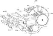
图1是本发明的实施例的柱塞泵动力端的示意图。FIG. 1 is a schematic diagram of a power end of a plunger pump according to an embodiment of the present invention.
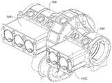
图2是本发明的实施例的柱塞泵动力端的爆炸图。FIG. 2 is an exploded view of the power end of the plunger pump according to the embodiment of the present invention.
图3是本发明的另一视角的实施例的柱塞泵动力端的爆炸图。FIG. 3 is an exploded view of the power end of the plunger pump according to another aspect of the present invention.
图4是本发明的实施例的柱塞泵动力端的部分结构示意图。FIG. 4 is a partial structural schematic diagram of the power end of the plunger pump according to the embodiment of the present invention.
图5是图2的主视图的剖视图。FIG. 5 is a cross-sectional view of the front view of FIG. 2 .
图6是本发明的实施例的柱塞泵动力端的第一传动件的示意图。6 is a schematic diagram of the first transmission member of the power end of the plunger pump according to the embodiment of the present invention.
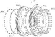
图7是本发明的实施例的柱塞泵动力端的人字齿轮组件的示意图。7 is a schematic diagram of the herringbone gear assembly at the power end of the plunger pump according to the embodiment of the present invention.
图8是本发明的实施例的柱塞泵动力端的人字齿轮组件的爆炸图。8 is an exploded view of the herringbone gear assembly at the power end of the plunger pump according to the embodiment of the present invention.
图9是本发明的实施例的柱塞泵动力端的花键套的示意图。FIG. 9 is a schematic diagram of the spline sleeve of the power end of the plunger pump according to the embodiment of the present invention.
附图标记:Reference number:
100、柱塞泵动力端;100. Power end of plunger pump;
1、减速箱体;101、轴承座;1. Gearbox body; 101. Bearing seat;
2、第一级传动组件;201、第一传动件;2011、第一传动轴;2012、第一斜齿圆柱齿轮;202、第二传动件;2021、第二传动轴;2022、第二斜齿圆柱齿轮;2023、人字齿轮段;204、第一圆柱滚子轴承;205、第一圆锥滚子轴承;206、第二圆柱滚子轴承;207、第二圆锥滚子轴承;2. The first-stage transmission assembly; 201, the first transmission member; 2011, the first transmission shaft; 2012, the first helical spur gear; 202, the second transmission member; 2021, the second transmission shaft; 2022, the second helical gear Tooth cylindrical gear; 2023, herringbone gear segment; 204, the first cylindrical roller bearing; 205, the first tapered roller bearing; 206, the second cylindrical roller bearing; 207, the second tapered roller bearing;
3、第二级传动组件;301、人字齿轮组件;3011、轮毂;3012、人字左旋齿轮;3013、人字右旋齿轮;3014、花键套;30141、外花键;30142、内花键;30143、挡圈槽;3015、第三圆柱滚子轴承;3016、螺杆;3017、螺帽;3018、防松垫片;3019、挡圈;302、曲轴;3021、第一曲轴;3022、第二曲轴;303、导向组件;3031、第一导向箱体;3032、第一十字头连杆部件;3033、第一拉杆;3034、第二导向箱体;3035、第二十字头连杆部件;3036、第二拉杆;304、第一曲轴箱体;305、第二曲轴箱体。3. Second-stage transmission assembly; 301, herringbone gear assembly; 3011, hub; 3012, herringbone left-handed gear; 3013, herringbone right-handed gear; 3014, spline sleeve; 30141, external spline; 30142, internal flower Key; 30143, retaining ring groove; 3015, third cylindrical roller bearing; 3016, screw; 3017, nut; 3018, lock washer; 3019, retaining ring; 302, crankshaft; 3021, first crankshaft; 3022, 303, the guide assembly; 3031, the first guide box; 3032, the first crosshead connecting rod; 3033, the first tie rod; 3034, the second guide box; 3035, the second crosshead connecting rod ; 3036, the second tie rod; 304, the first crankcase; 305, the second crankcase.
具体实施方式Detailed ways
下面详细描述本发明的实施例,所述实施例的示例在附图中示出。下面通过参考附图描述的实施例是示例性的,旨在用于解释本发明,而不能理解为对本发明的限制。The following describes in detail the embodiments of the present invention, examples of which are illustrated in the accompanying drawings. The embodiments described below with reference to the accompanying drawings are exemplary, and are intended to explain the present invention and should not be construed as limiting the present invention.
下面参考附图1至图9描述根据本发明实施例的柱塞泵动力端100和柱塞泵。The following describes a plunger
如图1至图9所示,柱塞泵动力端100包括第一级传动组件2和第二级传动组件3。第一级传动组件2包括第一传动件201和第二传动件202,第一传动件201与第二传动件202啮合,第一传动件201的转动方向与第二传动件202的转动方向平行。第二级传动组件3包括人字齿轮组件301和曲轴302,人字齿轮组件301与第二传动件202啮合。As shown in FIGS. 1 to 9 , the
本发明实施例的柱塞泵动力端100作为压裂泵、固井泵、乳化液泵、喷雾泵的动力端使用。The
具有本发明实施例的柱塞泵动力端100的柱塞泵,采用包括第一级传动组件2和第二级传动组件3的二级传动减速,可以使得柱塞泵动力端100传动时更加平稳,柱塞泵动力端100的结构更加合理,并且可以提高柱塞泵行程、降低柱塞泵的冲次,明显延长柱塞泵易损件的使用寿命。The plunger pump with the
此外,第二级传动组件3(第二级传动)采用人字齿轮副可相互抵消轴向力,在人字齿轮组件301的支撑轴承设计上,不需要考虑轴向力,轴承选型大大简化,进一步便于柱塞泵动力端100的设计。In addition, the second-stage transmission assembly 3 (second-stage transmission) adopts the herringbone gear pair to offset the axial force. In the design of the support bearing of the
因此,本发明实施例的柱塞泵动力端100具有使用寿命长和便于设计加工等优点。Therefore, the
具有本发明实施例的柱塞泵动力端100的柱塞泵具有使用寿命长和便于设计加工等优点。The plunger pump having the
可选地,曲轴302包括第一曲轴3021和第二曲轴3022,第一曲轴3021和第二曲轴3022分别设在人字齿轮组件301的轴向两侧。Optionally, the
由于第一曲轴3021和第二曲轴3022分别排布于人字齿轮组件301的轴向两侧,可以使得第一曲轴3021和第二曲轴3022对应不同的缸体数量。例如,第一曲轴3021和第二曲轴3022分别可以对应两缸、三缸和四缸(对应的液力端也设计为两部分,分别设计为两缸、三缸和四缸)。对于五缸柱塞泵,柱塞泵动力端100可通过两缸和三缸组合实现,对于六缸柱塞泵;柱塞泵动力端100可通过三缸和三缸组合实现;对于七缸柱塞泵;柱塞泵动力端100可通过三缸和四缸组合实现。Since the
由此,便于柱塞泵动力端100的模块化设计,方便柱塞泵动力端100的加工制造。Therefore, the modular design of the
在一些实施例中,柱塞泵动力端100包括减速箱体1,第一级传动组件2和第二级传动组件3的至少一部分设在减速箱体1内。In some embodiments, the
可选地,如图1至图5所示,第一传动件201包括第一传动轴2011和第一斜齿圆柱齿轮2012,第一斜齿圆柱齿轮2012设在第一传动轴2011上,第一传动轴2011可枢转地与减速箱体1连接。第二传动件202包括第二传动轴2021和第二斜齿圆柱齿轮2022,第二斜齿圆柱齿轮2022设在第二传动轴2021上,第二传动轴2021可枢转地与减速箱体1连接。其中,第一斜齿圆柱齿轮2012与第二斜齿圆柱齿轮2022啮合。Optionally, as shown in FIGS. 1 to 5 , the
可以理解的是,第一传动件201和第二传动件202通过斜齿圆柱齿轮传动的方式进行传动,第一传动件201和第二传动件202的承载能力强,且可以提高第一传动件201和第二传动件202之间传动的平稳性。It can be understood that the
可选地,第一斜齿圆柱齿轮2012和第一传动轴2011一体成型。换言之,第一斜齿圆柱齿轮2012和第一传动轴2011形成齿轮轴。Optionally, the first
可选地,第二斜齿圆柱齿轮2022可拆卸地套设在第二传动轴2021上。Optionally, the second
可选地,柱塞泵动力端100还包括第一圆柱滚子轴承204、两个第一圆锥滚子轴承205、第二圆柱滚子轴承206和两个第二圆锥滚子轴承207。第一传动轴2011的一端通过第一圆柱滚子轴承204可枢转地与减速箱体1连接,第一传动轴2011侧另一端通过两个第一圆锥滚子轴承205可枢转地与减速箱体1连接,两个第一圆锥滚子轴承205面对面安装。第二传动轴2021的一端通过第二圆柱滚子轴承206可枢转地与减速箱体1连接,第二传动轴2021侧另一端通过两个第二圆锥滚子轴承207可枢转地与减速箱体1连接,两个第二圆锥滚子轴承207面对面安装。Optionally, the piston
例如,如图5所示,第一传动轴2011的左端通过第一圆柱滚子轴承204可枢转地与减速箱体1连接,第一传动轴2011的右端通过成对设置的第一圆锥滚子轴承205可枢转地与减速箱体1连接。第二传动轴2021的左端通过成对设置的第二圆锥滚子轴承207可枢转地与减速箱体1连接,第二传动轴2021的右端通过第二圆柱滚子轴承206可枢转地与减速箱体1连接。For example, as shown in FIG. 5 , the left end of the
考虑到第一斜齿圆柱齿轮2012与第二斜齿圆柱齿轮2022啮合会产轴向力,且第一传动轴2011的左端、第二传动轴2021的右端载荷较大,采用在同样尺寸下承载能力更高的圆柱滚子轴承定位该端(第一传动轴2011的左端、第二传动轴2021的右端)。此外,为了限制第一传动轴2011、第二传动轴2021的轴向窜动,在第一传动轴2011的右端、第二传动轴2021的左端分别采用了面对面安装的圆锥滚子轴承。Considering that the meshing of the first
由此,有利于提高柱塞泵动力端100的传动平稳性,有利于提高具有该柱塞泵动力端100的柱塞泵的工作可靠性。Therefore, it is beneficial to improve the transmission stability of the
可选地,第一圆柱滚子轴承204和第二圆柱滚子轴承206为NU型圆柱滚子轴承。Optionally, the first
可选地,如图5和图6所示,第二传动轴2021为齿轮轴,第二传动轴2021包括人字齿轮段2023,人字齿轮段2023与人字齿轮组件301啮合。Optionally, as shown in FIG. 5 and FIG. 6 , the
本发明实施例的柱塞泵动力端的第一级传动采用斜齿轮副,第二级传动采用人字齿轮副实现两级传动减速,在同样或更大速比的情况下人字齿轮组件301的外径会更小,便于实现柱塞泵冲程的最大化设计。In the embodiment of the present invention, the first-stage transmission of the power end of the plunger pump adopts a helical gear pair, and the second-stage transmission adopts a herringbone gear pair to realize two-stage transmission deceleration. The outer diameter will be smaller, allowing for a design that maximizes the stroke of the plunger pump.
可选地,人字齿轮组件301包括轮毂3011、人字左旋齿轮3012和人字右旋齿轮3013,轮毂3011套设曲轴302上。人字左旋齿轮3012和人字右旋齿轮3013套设在轮毂3011上,人字左旋齿轮3012和人字右旋齿轮3013均与人字齿轮段2023啮合。Optionally, the
例如,如图5所示,轮毂3011的左侧部分套设在第一曲轴3021上,轮毂3011的右侧部分套设在第二曲轴3022上。For example, as shown in FIG. 5 , the left part of the
可选地,如图7和图8所示,轮毂3011上设有多个第一连接孔,多个第一连接孔沿轮毂3011的周向间隔均布。人字左旋齿轮3012上设有多个第二连接孔,多个第二连接孔沿人字左旋齿轮3012的周向间隔均布。人字右旋齿轮3013上设有多个第三连接孔,多个第三连接孔沿人字右旋齿轮3013的周向间隔均布。一一对应。人字齿轮组件301还包括防松垫片3018、多个螺杆3016和多个螺帽3017,防松垫片3018上设有多个第四连接孔。其中,多个第一连接孔、多个第二连接孔、多个第三连接孔、多个第四连接孔、多个螺杆3016和多个螺帽3017一一对应。螺杆3016依次穿过对应的第三连接孔、第一连接孔、第二连接孔和第四连接孔并与对应的螺帽3017相连,将人字左旋齿轮3012和人字右旋齿轮3013固定轮毂3011上。从而提高人字齿轮组件301组装后的可靠性。Optionally, as shown in FIGS. 7 and 8 , the
本发明中的柱塞泵动力端100第二级传动采用组合式人字齿轮(人字齿轮组件301),无需考虑整体人字齿中间滚刀出刀槽宽度问题,可设计并制造出齿宽更小的齿轮,从而有利于进一步减小柱塞泵动力端100的长度。The second-stage transmission of the
可选地,如图5所示,柱塞泵动力端100还包括两个第三圆柱滚子轴承3015。轮毂3011的一端通过其中一个第三圆柱滚子轴承3015可枢转地与减速箱体1连接。轮毂3011的另一端通过另一个第三圆柱滚子轴承3015可枢转地与减速箱体1连接。两个第三圆柱滚子轴承3015在轮毂3011的轴向上具有浮动间隙。Optionally, as shown in FIG. 5 , the
例如,如图5所示,两个第三圆柱滚子轴承3015分别设在轮毂3011的左右两侧,减速箱体1上连接有两个轴承座101,两个轴承座101分别位于轮毂3011的左右两侧。左侧的第三圆柱滚子轴承3015安装在左侧的轴承座101和轮毂3011之间,右侧的第三圆柱滚子轴承3015安装在右侧的轴承座101和轮毂3011之间。For example, as shown in FIG. 5 , two third
可选地,第三圆柱滚子轴承3015为NJ型圆柱滚子轴承。成对使用的NJ型轴承在轴向上可设计一定的浮动间隙,使得人字齿轮组件301在人字齿轮段2023的作用下“自动对中”,找到最佳的啮合位置。此外,人字齿轮组件301由两个相同型号的、外圈及内圈可分离的圆柱滚子支撑,便于安装,承载能力强。Optionally, the third
可选地,人字齿轮组件301还包括花键套3014,花键套3014的外周壁具有外花键30141,花键套3014的内周壁具有内花键30142,花键套3014的外周壁与轮毂3011的内周壁配合。花键套3014的内周壁与曲轴302配合。Optionally, the
例如,如图5和图9所示,轮毂3011的内周壁具有内花键,花键套3014的外花键30141与轮毂3011的内花键配合,实现轮毂3011和花键套3014的止转配合。花键套3014的内花键30142的左侧部分与第一曲轴3021配合,花键套3014的内花键30142的右侧部分与第二曲轴3022配合,实现轮毂3011与第一曲轴3021和第二曲轴3022的周向止转连接。For example, as shown in FIG. 5 and FIG. 9 , the inner peripheral wall of the
可选地,如图5和图9所示,花键套3014的内周壁具有挡圈槽30143,挡圈槽30143内设有挡圈3019,利用挡圈3019限制第一曲轴3021和第二曲轴3022的左右移动,而稳定地将人字齿轮组件301的扭矩传递给第一曲轴3021和第二曲轴3022。Optionally, as shown in FIG. 5 and FIG. 9 , the inner peripheral wall of the
由此,使得柱塞泵动力端100的传动平稳性较好,且便于制造和加工,使用成本较低。Therefore, the driving stability of the
在一些实施例中,柱塞泵动力端100包括第一曲轴箱体304和第二曲轴箱体305,第一曲轴箱体304与减速箱体1相连,第一曲轴3021设在第一曲轴箱体304内。第二曲轴箱体305与减速箱体1相连,第二曲轴3022设在第二曲轴箱体305内。其中,第一曲轴箱体304和第二曲轴箱体305在人字齿轮组件301的轴向上分别位于减速箱体1的两侧。In some embodiments, the
本发明实施例的柱塞泵动力端100,将减速箱体1设置在中部,曲轴箱体分为第一曲轴箱体304和第二曲轴箱体305两部分,且第一曲轴箱体304和第二曲轴箱体305分别设计在减速箱体1的左、右两侧。由此,第一曲轴箱体304和第二曲轴箱体305分别可设计为两缸、三缸和四缸(对应的液力端也设计为两部分,分别设计为两缸、三缸和四缸),进一步便于柱塞泵动力端100的模块化设计,方便柱塞泵动力端100的加工制造。In the
在一些实施例中,如图1至图4所示,柱塞泵动力端100还包括导向组件303,导向组件303包括导向箱体、十字头连杆部件和拉杆,导向箱体与减速箱体1相连。十字头连杆部件设在导向箱体内,十字头连杆部件与曲轴302相连,十字头连杆部件与拉杆相连,以推动拉杆作往复运动。In some embodiments, as shown in FIGS. 1 to 4 , the
例如,如图1至图4所示,导向箱体包括第一导向箱体3031和第二导向箱体3034,十字头连杆部件包括第一十字头连杆部件3032和第二十字头连杆部件3035,拉杆包括第一拉杆3033和第二拉杆3036。第一导向箱体3031与第一曲轴箱体304相连。第一十字头连杆部件3032设在第一导向箱体3031内,第一十字头连杆部件3032与第一曲轴3021相连,第一十字头连杆部件3032与第一拉杆3033相连,以推动第一拉杆3033作往复运动。第一导向箱体3031与第二曲轴箱体305相连。第二十字头连杆部件3035设在第二导向箱体3034内,第二十字头连杆部件3035与第二曲轴3022相连,第二十字头连杆部件3035与第二拉杆3036相连,以推动第二拉杆3036作往复运动。For example, as shown in FIG. 1 to FIG. 4 , the guide box includes a
如图1至图4所示,第一导向箱体3031和第二导向箱体3034可以根据需要设置为两缸、三缸或四缸,同时,且不同缸体数量的第一导向箱体3031和第二导向箱体3034可以根据实际设计需要进行组合,以满足柱塞泵的不同应用场景,从而提高了柱塞泵的使用范围,降低设计和生产成本。As shown in FIG. 1 to FIG. 4 , the
例如,第一导向箱体3031设置为三缸,第二导向箱体3034设置为两缸。对应的柱塞泵为五缸。For example, the
可选地,如图5所示,第一级传动组件1设在第一导向箱体3031和第二导向箱体3034的下方。Optionally, as shown in FIG. 5 , the first-stage transmission assembly 1 is provided below the
由此,使得第一级传动组件1不占用柱塞泵的总体长度,使柱塞泵在长度方向上尺寸更小、结构更紧凑。此外,双级传动的设计方式更有利于柱塞泵输入轴空间位置的调整。当柱塞泵为压裂泵时,有利于压裂泵与压裂车底盘上发动机、液力变速器输出轴的连接设计。Therefore, the first-stage transmission assembly 1 does not occupy the entire length of the plunger pump, so that the plunger pump has a smaller size and a more compact structure in the longitudinal direction. In addition, the design of the two-stage transmission is more conducive to the adjustment of the spatial position of the input shaft of the plunger pump. When the plunger pump is a fracturing pump, it is favorable for the connection design of the fracturing pump to the engine and the output shaft of the hydraulic transmission on the chassis of the fracturing vehicle.
本发明实施例的柱塞泵为往复式柱塞泵,柱塞泵包括动力端和液力端,动力端为上述任一实施例所述的柱塞泵动力端。液力端包括柱塞,曲轴302与柱塞传动连接。The plunger pump of the embodiment of the present invention is a reciprocating plunger pump, the plunger pump includes a power end and a hydraulic end, and the power end is the power end of the plunger pump described in any of the above embodiments. The hydraulic end includes a plunger, and the
例如,柱塞包括第一柱塞和第二柱塞,第一曲轴3021与第一柱塞传动连接,第二曲轴3022与第二柱塞传动连接,以便利用动力端的曲轴(第一曲轴和第二曲轴)驱动液力端的柱塞(第一柱塞和第二柱塞)往复移动。具体地,第一曲轴3021通过第一拉杆3033与第一柱塞相连,第二曲轴3022通过第二拉杆3036与第二柱塞相连。For example, the plunger includes a first plunger and a second plunger, the
柱塞泵可以为压裂泵、固井泵、乳化液泵、喷雾泵等。The plunger pump can be a fracturing pump, a cementing pump, an emulsion pump, a spray pump, and the like.
可选地,第一柱塞和第二柱塞均设有多个。Optionally, a plurality of the first plunger and the second plunger are provided.
本发明实施例的柱塞泵具有以下优点:The plunger pump of the embodiment of the present invention has the following advantages:
两级传动减速的设置,可以减小柱塞泵最终传动大齿轮(人字齿轮组件301)的外径,进而实现柱塞泵宽度的最小化、高度的最小化、冲程最大化、冲次最低化,延长柱塞泵使用寿命。例如,延长柱塞泵的阀体、阀座、盘根密封、柱塞等易损件的使用寿命。往复式柱塞的模块化设计,可以降低设计成本和生产成本。输入轴(第一传动轴2011)设计在导向箱体的下方,可以减小柱塞泵的总体长度,便于压裂车、压裂撬或泵组的总体方案设计。The setting of two-stage transmission reduction can reduce the outer diameter of the final drive gear (herringbone gear assembly 301) of the plunger pump, thereby realizing the minimization of the width, height, maximum stroke and minimum stroke of the plunger pump. to prolong the service life of the plunger pump. For example, to prolong the service life of wearing parts such as valve body, valve seat, packing seal and plunger of plunger pump. The modular design of the reciprocating plunger can reduce the design cost and production cost. The input shaft (the first transmission shaft 2011) is designed below the guide box, which can reduce the overall length of the plunger pump and facilitate the overall design of the fracturing truck, fracturing skid or pump set.
在本发明的描述中,需要理解的是,术语“中心”、“纵向”、“横向”、“长度”、“宽度”、“厚度”、“上”、“下”、“前”、“后”、“左”、“右”、“竖直”、“水平”、“顶”、“底”“内”、“外”、“顺时针”、“逆时针”、“轴向”、“径向”、“周向”等指示的方位或位置关系为基于附图所示的方位或位置关系,仅是为了便于描述本发明和简化描述,而不是指示或暗示所指的装置或元件必须具有特定的方位、以特定的方位构造和操作,因此不能理解为对本发明的限制。In the description of the present invention, it should be understood that the terms "center", "longitudinal", "lateral", "length", "width", "thickness", "upper", "lower", "front", " Rear, Left, Right, Vertical, Horizontal, Top, Bottom, Inner, Outer, Clockwise, Counterclockwise, Axial, The orientations or positional relationships indicated by "radial direction", "circumferential direction", etc. are based on the orientations or positional relationships shown in the accompanying drawings, which are only for the convenience of describing the present invention and simplifying the description, rather than indicating or implying the indicated devices or elements. It must have a specific orientation, be constructed and operate in a specific orientation, and therefore should not be construed as a limitation of the present invention.
此外,术语“第一”、“第二”仅用于描述目的,而不能理解为指示或暗示相对重要性或者隐含指明所指示的技术特征的数量。由此,限定有“第一”、“第二”的特征可以明示或者隐含地包括至少一个该特征。在本发明的描述中,“多个”的含义是至少两个,例如两个,三个等,除非另有明确具体的限定。In addition, the terms "first" and "second" are only used for descriptive purposes, and should not be construed as indicating or implying relative importance or implying the number of indicated technical features. Thus, a feature delimited with "first", "second" may expressly or implicitly include at least one of that feature. In the description of the present invention, "plurality" means at least two, such as two, three, etc., unless otherwise expressly and specifically defined.
在本发明中,除非另有明确的规定和限定,术语“安装”、“相连”、“连接”、“固定”等术语应做广义理解,例如,可以是固定连接,也可以是可拆卸连接,或成一体;可以是机械连接,也可以是电连接或彼此可通讯;可以是直接相连,也可以通过中间媒介间接相连,可以是两个元件内部的连通或两个元件的相互作用关系,除非另有明确的限定。对于本领域的普通技术人员而言,可以根据具体情况理解上述术语在本发明中的具体含义。In the present invention, unless otherwise expressly specified and limited, the terms "installed", "connected", "connected", "fixed" and other terms should be understood in a broad sense, for example, it may be a fixed connection or a detachable connection , or integrated; it can be a mechanical connection or an electrical connection or can communicate with each other; it can be directly connected or indirectly connected through an intermediate medium, it can be the internal connection of two components or the interaction relationship between the two components, unless otherwise expressly qualified. For those of ordinary skill in the art, the specific meanings of the above terms in the present invention can be understood according to specific situations.
在本发明中,除非另有明确的规定和限定,第一特征在第二特征“上”或“下”可以是第一和第二特征直接接触,或第一和第二特征通过中间媒介间接接触。而且,第一特征在第二特征“之上”、“上方”和“上面”可是第一特征在第二特征正上方或斜上方,或仅仅表示第一特征水平高度高于第二特征。第一特征在第二特征“之下”、“下方”和“下面”可以是第一特征在第二特征正下方或斜下方,或仅仅表示第一特征水平高度小于第二特征。In the present invention, unless otherwise expressly specified and limited, a first feature "on" or "under" a second feature may be in direct contact between the first and second features, or the first and second features indirectly through an intermediary touch. Also, the first feature being "above", "over" and "above" the second feature may mean that the first feature is directly above or obliquely above the second feature, or simply means that the first feature is level higher than the second feature. The first feature being "below", "below" and "below" the second feature may mean that the first feature is directly below or obliquely below the second feature, or simply means that the first feature has a lower level than the second feature.
在本发明中,术语“一个实施例”、“一些实施例”、“示例”、“具体示例”、或“一些示例”等意指结合该实施例或示例描述的具体特征、结构、材料或者特点包含于本发明的至少一个实施例或示例中。在本说明书中,对上述术语的示意性表述不必须针对的是相同的实施例或示例。而且,描述的具体特征、结构、材料或者特点可以在任一个或多个实施例或示例中以合适的方式结合。此外,在不相互矛盾的情况下,本领域的技术人员可以将本说明书中描述的不同实施例或示例以及不同实施例或示例的特征进行结合和组合。In this disclosure, the terms "one embodiment," "some embodiments," "example," "specific example," or "some examples" and the like mean a specific feature, structure, material, or description described in connection with the embodiment or example. Features are included in at least one embodiment or example of the invention. In this specification, schematic representations of the above terms are not necessarily directed to the same embodiment or example. Furthermore, the particular features, structures, materials or characteristics described may be combined in any suitable manner in any one or more embodiments or examples. Furthermore, those skilled in the art may combine and combine the different embodiments or examples described in this specification, as well as the features of the different embodiments or examples, without conflicting each other.
尽管上面已经示出和描述了本发明的实施例,可以理解的是,上述实施例是示例性的,不能理解为对本发明的限制,本领域的普通技术人员在本发明的范围内可以对上述实施例进行变化、修改、替换和变型。Although the embodiments of the present invention have been shown and described above, it should be understood that the above-mentioned embodiments are exemplary and should not be construed as limiting the present invention. Embodiments are subject to variations, modifications, substitutions and variations.
Claims (10)
Translated fromChinesePriority Applications (1)
| Application Number | Priority Date | Filing Date | Title |
|---|---|---|---|
| CN202210406805.0ACN114810979A (en) | 2022-04-18 | 2022-04-18 | Plunger pump power end and plunger pump with same |
Applications Claiming Priority (1)
| Application Number | Priority Date | Filing Date | Title |
|---|---|---|---|
| CN202210406805.0ACN114810979A (en) | 2022-04-18 | 2022-04-18 | Plunger pump power end and plunger pump with same |
Publications (1)
| Publication Number | Publication Date |
|---|---|
| CN114810979Atrue CN114810979A (en) | 2022-07-29 |
Family
ID=82536132
Family Applications (1)
| Application Number | Title | Priority Date | Filing Date |
|---|---|---|---|
| CN202210406805.0APendingCN114810979A (en) | 2022-04-18 | 2022-04-18 | Plunger pump power end and plunger pump with same |
Country Status (1)
| Country | Link |
|---|---|
| CN (1) | CN114810979A (en) |
Citations (11)
| Publication number | Priority date | Publication date | Assignee | Title |
|---|---|---|---|---|
| CN202946334U (en)* | 2013-03-15 | 2013-05-22 | 天津市通洁高压泵制造有限公司 | Large-power five-plunger high pressure reciprocation pump |
| CN104100483A (en)* | 2014-08-06 | 2014-10-15 | 何有山 | Mining plunger pump driven by herringbone gear bank |
| CN109869294A (en)* | 2019-04-19 | 2019-06-11 | 烟台杰瑞石油装备技术有限公司 | A kind of super high power Five-cylinder piston pump |
| CN109882144A (en)* | 2019-04-19 | 2019-06-14 | 烟台杰瑞石油装备技术有限公司 | Double-motor double-pump electric driving fracturing semitrailer |
| CN110485984A (en)* | 2019-09-20 | 2019-11-22 | 烟台杰瑞石油装备技术有限公司 | A kind of turbine fracturing unit that semi-mounted is vehicle-mounted |
| CN110486249A (en)* | 2019-09-20 | 2019-11-22 | 烟台杰瑞石油装备技术有限公司 | A kind of Five-cylinder piston pump |
| CN111425177A (en)* | 2020-04-30 | 2020-07-17 | 三一石油智能装备有限公司 | A fracturing pump and fracturing truck |
| CN111749863A (en)* | 2020-07-25 | 2020-10-09 | 烟台杰瑞石油装备技术有限公司 | Seven-cylinder plunger pump |
| US20210140416A1 (en)* | 2019-11-11 | 2021-05-13 | St9 Gas And Oil, Llc | Power end for hydraulic fracturing pump |
| CN112901478A (en)* | 2021-03-01 | 2021-06-04 | 北京天地玛珂电液控制系统有限公司 | Plunger pump |
| CN114135462A (en)* | 2021-10-25 | 2022-03-04 | 北京天玛智控科技股份有限公司 | Internally Lubricated Piston Pump |
- 2022
- 2022-04-18CNCN202210406805.0Apatent/CN114810979A/enactivePending
Patent Citations (11)
| Publication number | Priority date | Publication date | Assignee | Title |
|---|---|---|---|---|
| CN202946334U (en)* | 2013-03-15 | 2013-05-22 | 天津市通洁高压泵制造有限公司 | Large-power five-plunger high pressure reciprocation pump |
| CN104100483A (en)* | 2014-08-06 | 2014-10-15 | 何有山 | Mining plunger pump driven by herringbone gear bank |
| CN109869294A (en)* | 2019-04-19 | 2019-06-11 | 烟台杰瑞石油装备技术有限公司 | A kind of super high power Five-cylinder piston pump |
| CN109882144A (en)* | 2019-04-19 | 2019-06-14 | 烟台杰瑞石油装备技术有限公司 | Double-motor double-pump electric driving fracturing semitrailer |
| CN110485984A (en)* | 2019-09-20 | 2019-11-22 | 烟台杰瑞石油装备技术有限公司 | A kind of turbine fracturing unit that semi-mounted is vehicle-mounted |
| CN110486249A (en)* | 2019-09-20 | 2019-11-22 | 烟台杰瑞石油装备技术有限公司 | A kind of Five-cylinder piston pump |
| US20210140416A1 (en)* | 2019-11-11 | 2021-05-13 | St9 Gas And Oil, Llc | Power end for hydraulic fracturing pump |
| CN111425177A (en)* | 2020-04-30 | 2020-07-17 | 三一石油智能装备有限公司 | A fracturing pump and fracturing truck |
| CN111749863A (en)* | 2020-07-25 | 2020-10-09 | 烟台杰瑞石油装备技术有限公司 | Seven-cylinder plunger pump |
| CN112901478A (en)* | 2021-03-01 | 2021-06-04 | 北京天地玛珂电液控制系统有限公司 | Plunger pump |
| CN114135462A (en)* | 2021-10-25 | 2022-03-04 | 北京天玛智控科技股份有限公司 | Internally Lubricated Piston Pump |
Similar Documents
| Publication | Publication Date | Title |
|---|---|---|
| CN201196116Y (en) | Horizontal sector-shape rack-and-pinion engine | |
| US8083504B2 (en) | Quintuplex mud pump | |
| WO2020211083A1 (en) | Super-power five-cylinder piston pump | |
| CN110486249A (en) | A kind of Five-cylinder piston pump | |
| CN101979853B (en) | Internal dual-phase shockwave swing link transmission type internal combustion engine | |
| CN102207179B (en) | Rotary motion and reciprocating motion converting device | |
| CN103470382B (en) | A kind of engine compression ratio controlling mechanism | |
| CN201025125Y (en) | Double-sided rack drive fuel engine | |
| CN111997856A (en) | Two-dimensional piston pump with series-parallel structure | |
| CN113464392A (en) | High-power five-cylinder drilling pump, drilling pump set, solid control system and drilling machine | |
| CN111749863A (en) | Seven-cylinder plunger pump | |
| CN102926862B (en) | Convex inner two-phase cam rolling shifting transmission internal-combustion engine | |
| WO2007095838A1 (en) | A driving mechanism of a crankless engine | |
| CN101634286A (en) | Low-noise reciprocating piston compressor | |
| CN103016149A (en) | Hydraulic engine with inter-cylinder gear linkage function | |
| CN114810979A (en) | Plunger pump power end and plunger pump with same | |
| CN110566426A (en) | Double-acting groove cam constant-flow reciprocating pump | |
| CN213870159U (en) | Novel electro-hydraulic motor | |
| CN114810947A (en) | Piston Pumps and Piston Pump Power Ends | |
| CN101776009B (en) | Piston-type direct-drive engine and design method for first taking force and then integrating | |
| CN213684926U (en) | Novel high-power seven-cylinder plunger pump crankshaft | |
| CN212717025U (en) | Seven-cylinder plunger pump | |
| CN101509423A (en) | A hypocycloidal single-cylinder diesel engine | |
| CN212296619U (en) | Cross connecting rod double-crankshaft power transmission mechanism | |
| CN112196760A (en) | Novel electro-hydraulic motor |
Legal Events
| Date | Code | Title | Description |
|---|---|---|---|
| PB01 | Publication | ||
| PB01 | Publication | ||
| SE01 | Entry into force of request for substantive examination | ||
| SE01 | Entry into force of request for substantive examination |